EP3082001B1 - Method for expanding an automation device using a virtual field device and automation device - Google Patents
Method for expanding an automation device using a virtual field device and automation device Download PDFInfo
- Publication number
- EP3082001B1 EP3082001B1 EP15163409.4A EP15163409A EP3082001B1 EP 3082001 B1 EP3082001 B1 EP 3082001B1 EP 15163409 A EP15163409 A EP 15163409A EP 3082001 B1 EP3082001 B1 EP 3082001B1
- Authority
- EP
- European Patent Office
- Prior art keywords
- control
- load
- communication
- automation
- automation device
- Prior art date
- Legal status (The legal status is an assumption and is not a legal conclusion. Google has not performed a legal analysis and makes no representation as to the accuracy of the status listed.)
- Active
Links
- 238000000034 method Methods 0.000 title claims description 19
- 238000004891 communication Methods 0.000 claims description 66
- 238000004886 process control Methods 0.000 claims description 18
- 230000008569 process Effects 0.000 claims description 12
- 238000012545 processing Methods 0.000 claims description 12
- 238000012806 monitoring device Methods 0.000 claims description 9
- 238000012407 engineering method Methods 0.000 claims description 5
- 230000006870 function Effects 0.000 description 9
- 238000004519 manufacturing process Methods 0.000 description 9
- 230000004913 activation Effects 0.000 description 2
- 230000001632 homeopathic effect Effects 0.000 description 2
- 230000010354 integration Effects 0.000 description 2
- 238000012360 testing method Methods 0.000 description 2
- 230000009471 action Effects 0.000 description 1
- 239000003337 fertilizer Substances 0.000 description 1
- 238000010438 heat treatment Methods 0.000 description 1
- 230000000977 initiatory effect Effects 0.000 description 1
- 230000003993 interaction Effects 0.000 description 1
- 230000002452 interceptive effect Effects 0.000 description 1
- 239000000463 material Substances 0.000 description 1
- 238000002360 preparation method Methods 0.000 description 1
- 230000003068 static effect Effects 0.000 description 1
- 238000003756 stirring Methods 0.000 description 1
- 238000003860 storage Methods 0.000 description 1
- 238000004808 supercritical fluid chromatography Methods 0.000 description 1
- 239000000979 synthetic dye Substances 0.000 description 1
- 229920003002 synthetic resin Polymers 0.000 description 1
- 239000000057 synthetic resin Substances 0.000 description 1
- 230000007704 transition Effects 0.000 description 1
Images
Classifications
-
- G—PHYSICS
- G05—CONTROLLING; REGULATING
- G05B—CONTROL OR REGULATING SYSTEMS IN GENERAL; FUNCTIONAL ELEMENTS OF SUCH SYSTEMS; MONITORING OR TESTING ARRANGEMENTS FOR SUCH SYSTEMS OR ELEMENTS
- G05B19/00—Programme-control systems
- G05B19/02—Programme-control systems electric
- G05B19/04—Programme control other than numerical control, i.e. in sequence controllers or logic controllers
- G05B19/048—Monitoring; Safety
-
- G—PHYSICS
- G06—COMPUTING; CALCULATING OR COUNTING
- G06F—ELECTRIC DIGITAL DATA PROCESSING
- G06F30/00—Computer-aided design [CAD]
- G06F30/10—Geometric CAD
- G06F30/17—Mechanical parametric or variational design
-
- G—PHYSICS
- G05—CONTROLLING; REGULATING
- G05B—CONTROL OR REGULATING SYSTEMS IN GENERAL; FUNCTIONAL ELEMENTS OF SUCH SYSTEMS; MONITORING OR TESTING ARRANGEMENTS FOR SUCH SYSTEMS OR ELEMENTS
- G05B19/00—Programme-control systems
- G05B19/02—Programme-control systems electric
- G05B19/04—Programme control other than numerical control, i.e. in sequence controllers or logic controllers
- G05B19/042—Programme control other than numerical control, i.e. in sequence controllers or logic controllers using digital processors
- G05B19/0426—Programming the control sequence
-
- G—PHYSICS
- G05—CONTROLLING; REGULATING
- G05B—CONTROL OR REGULATING SYSTEMS IN GENERAL; FUNCTIONAL ELEMENTS OF SUCH SYSTEMS; MONITORING OR TESTING ARRANGEMENTS FOR SUCH SYSTEMS OR ELEMENTS
- G05B19/00—Programme-control systems
- G05B19/02—Programme-control systems electric
- G05B19/04—Programme control other than numerical control, i.e. in sequence controllers or logic controllers
- G05B19/05—Programmable logic controllers, e.g. simulating logic interconnections of signals according to ladder diagrams or function charts
- G05B19/056—Programming the PLC
-
- G—PHYSICS
- G05—CONTROLLING; REGULATING
- G05B—CONTROL OR REGULATING SYSTEMS IN GENERAL; FUNCTIONAL ELEMENTS OF SUCH SYSTEMS; MONITORING OR TESTING ARRANGEMENTS FOR SUCH SYSTEMS OR ELEMENTS
- G05B19/00—Programme-control systems
- G05B19/02—Programme-control systems electric
- G05B19/418—Total factory control, i.e. centrally controlling a plurality of machines, e.g. direct or distributed numerical control [DNC], flexible manufacturing systems [FMS], integrated manufacturing systems [IMS] or computer integrated manufacturing [CIM]
- G05B19/4183—Total factory control, i.e. centrally controlling a plurality of machines, e.g. direct or distributed numerical control [DNC], flexible manufacturing systems [FMS], integrated manufacturing systems [IMS] or computer integrated manufacturing [CIM] characterised by data acquisition, e.g. workpiece identification
-
- G—PHYSICS
- G05—CONTROLLING; REGULATING
- G05B—CONTROL OR REGULATING SYSTEMS IN GENERAL; FUNCTIONAL ELEMENTS OF SUCH SYSTEMS; MONITORING OR TESTING ARRANGEMENTS FOR SUCH SYSTEMS OR ELEMENTS
- G05B19/00—Programme-control systems
- G05B19/02—Programme-control systems electric
- G05B19/418—Total factory control, i.e. centrally controlling a plurality of machines, e.g. direct or distributed numerical control [DNC], flexible manufacturing systems [FMS], integrated manufacturing systems [IMS] or computer integrated manufacturing [CIM]
- G05B19/41835—Total factory control, i.e. centrally controlling a plurality of machines, e.g. direct or distributed numerical control [DNC], flexible manufacturing systems [FMS], integrated manufacturing systems [IMS] or computer integrated manufacturing [CIM] characterised by programme execution
-
- G—PHYSICS
- G06—COMPUTING; CALCULATING OR COUNTING
- G06F—ELECTRIC DIGITAL DATA PROCESSING
- G06F30/00—Computer-aided design [CAD]
- G06F30/20—Design optimisation, verification or simulation
-
- G—PHYSICS
- G05—CONTROLLING; REGULATING
- G05B—CONTROL OR REGULATING SYSTEMS IN GENERAL; FUNCTIONAL ELEMENTS OF SUCH SYSTEMS; MONITORING OR TESTING ARRANGEMENTS FOR SUCH SYSTEMS OR ELEMENTS
- G05B2219/00—Program-control systems
- G05B2219/20—Pc systems
- G05B2219/25—Pc structure of the system
- G05B2219/25428—Field device
-
- G—PHYSICS
- G05—CONTROLLING; REGULATING
- G05B—CONTROL OR REGULATING SYSTEMS IN GENERAL; FUNCTIONAL ELEMENTS OF SUCH SYSTEMS; MONITORING OR TESTING ARRANGEMENTS FOR SUCH SYSTEMS OR ELEMENTS
- G05B2219/00—Program-control systems
- G05B2219/30—Nc systems
- G05B2219/31—From computer integrated manufacturing till monitoring
- G05B2219/31018—Virtual factory, modules in network, can be selected and combined at will
-
- G—PHYSICS
- G05—CONTROLLING; REGULATING
- G05B—CONTROL OR REGULATING SYSTEMS IN GENERAL; FUNCTIONAL ELEMENTS OF SUCH SYSTEMS; MONITORING OR TESTING ARRANGEMENTS FOR SUCH SYSTEMS OR ELEMENTS
- G05B2219/00—Program-control systems
- G05B2219/30—Nc systems
- G05B2219/31—From computer integrated manufacturing till monitoring
- G05B2219/31135—Fieldbus
-
- G—PHYSICS
- G05—CONTROLLING; REGULATING
- G05B—CONTROL OR REGULATING SYSTEMS IN GENERAL; FUNCTIONAL ELEMENTS OF SUCH SYSTEMS; MONITORING OR TESTING ARRANGEMENTS FOR SUCH SYSTEMS OR ELEMENTS
- G05B2219/00—Program-control systems
- G05B2219/30—Nc systems
- G05B2219/31—From computer integrated manufacturing till monitoring
- G05B2219/31229—Supervisor, master, workstation controller, automation, machine control
-
- G—PHYSICS
- G05—CONTROLLING; REGULATING
- G05B—CONTROL OR REGULATING SYSTEMS IN GENERAL; FUNCTIONAL ELEMENTS OF SUCH SYSTEMS; MONITORING OR TESTING ARRANGEMENTS FOR SUCH SYSTEMS OR ELEMENTS
- G05B2219/00—Program-control systems
- G05B2219/30—Nc systems
- G05B2219/32—Operator till task planning
- G05B2219/32128—Gui graphical user interface
Definitions
- the invention relates to a method for expanding an automation device with a field device, wherein the automation device has at least one automation device and at least one field device that are connected to a communication link, and wherein the automation device is further configured by an engineering method for solving an automation task in such a way that the At least one automation device processes a configured control program during process control, which control program comprises a plurality of control modules.
- the invention also relates to an automation device according to the preamble of claim 3 for carrying out the method.
- an engineering system of an automation device is known, which is designed to configure both hardware and software automation components of the automation device, in particular in the context of "engineering of automation” a user a control program for controlling a technical process or a system to be controlled created or configured.
- Such a plant is usually not a static production facility that is once planned, built and commissioned and then not changed again. Rather, the system is subject to constant changes and adjustments in order to optimize and expand production. For this, it is usually necessary to also integrate new process-related automation components in the form of further field devices into the automation device.
- the power reserves of the controller and the communication network can be estimated as part of the project planning of extensions to the automation device.
- the many years of experience of the project engineers play an important role. Based on these estimates or assumptions, commissioning never takes place without a residual risk. This residual risk can be reduced by installing a corresponding "shadow system or automation device" is set up to test the functionality and commissioning in advance. This means considerable material and personnel costs, with a shadow system for the preparation of the expansion also usually only representing a replica of the system and never an exact copy.
- DE 102 45 176 A1 discloses a method for simulating a field device.
- the invention is therefore based on the object of carrying out a method according to claim 1.
- an automation device is to be implemented in accordance with claim 2. This object is achieved with regard to the method by the measures given in the characterizing part of claim 1, and with regard to the automation device by the measures given in the characterizing part of claim 2.
- a user can configure several virtual field devices, each representing a real field device and emulating these real field devices. These virtual field devices are connected to the automation device or activated one after the other, with the current communication load and the current control load of the automation device being recorded after each connection of one of the virtual field devices. In the event that the current communication load has a communication load limit and If the current tax load does not exceed a control load limit, the user can finally expand the automation device to include the real field device that was emulated by the connected virtual field device.
- a further one of the virtual field devices can then be connected in order to again check whether the automation device can be expanded by a real field device corresponding to this virtual field device.
- the user is always shown how high the current communication and control load is, so that the automation device can be brought up to the communication and control load limits in "homeopathic doses" (by adding another virtual field device).
- the existing automation device must first be expanded with one or more automation devices and / or communication means.
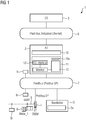
- FIG. 1 1 shows an automation device 1 configured by means of an engineering system (not shown here).
- this includes an automation device 2, an OS client or an operating and monitoring device 3 of an OS operator system, which also has an OS server (not shown here), a decentralized periphery 4 and a communication participant 5.
- the automation device 2 communicates with the OS client 3 via a communication link 6 and via a further communication link 7 with the decentralized periphery 4 and a communication subscriber 5, the communication links 6, 7 being designed as bus links.
- a multiplicity of field devices 9 (actuators, sensors) is connected to the bus 7 and / or to a further bus 8 connected to the decentralized periphery 4, the field devices 9 by means of during process control, ie during the run operation of the automation device 2
- Control modules are controlled. These control modules are part of a control program which is configured or created in accordance with an automation task to be solved during engineering using an engineering method.
- An engineering or engineering method known per se for creating a control program is based on a continuous function chart (CFC) that can run on the engineering system and on sequential continuous function chart (SFC) editors.
- CFC continuous function chart
- SFC sequential continuous function chart
- a user graphically creates the control program for the automation device 2 from prefabricated blocks in accordance with the automation task to be solved and selects the blocks for this purpose, e.g. B. a controller or counter block from an available block pool, the blocks z. For example, by dragging and dropping in a function chart (e.g. CFC chart) and interconnecting them with a click of the mouse.
- a function chart e.g. CFC chart
- the engineering system After the user has created all functions in the function plan, the engineering system generates 2 readable CFC functions through the automation device, the loaded into this automation device 2 and processed there as part of the process control to solve the automation task.
- SCF process control
- the user also creates a process control (SCF) graphically in the usual way, which usually comprises a large number of step chains, which in turn have a large number of recipe elements and transitions, e.g. B. recipe elements in the form of recipe operations or recipe functions, e.g. B. dosing, heating or stirring.
- SCF process control
- the engineering system From this sequence control, the engineering system generates (SFC) objects that can be processed by the automation device 2, which the engineering system compiles and loads into the automation device 2.
- process control - i.e.
- process values and control signals SFC data
- process input values actual values
- process output values setpoints
- a configured control program 10 (SFCs, CFCs) is stored in the automation device 2 and the automation device 2 is currently processing this control program 10 for process control.
- SFCs, CFCs configured control program 10
- the automation device 2 is currently processing this control program 10 for process control.
- communication participants 5 for each of these Field devices 9r are a virtual field device 5v configured by the engineering system and an expansion module 11 is also stored in the automation device 2, which has a configured control module 10s for each virtual field device 5v for controlling the respective virtual field device 5v.
- These virtual field devices 5v represent the real field devices and are designed to emulate the real field devices.
- the expansion module 11 is also provided with an OS interface 12 for exchanging information between the expansion module 11 and the OS client 3, the user initiating the expansion of the automation device 1 by making a corresponding input on the OS client 3 and on the other hand the OS client 3 shows the user the current communication and control load.
- the user can activate the respective control modules 10s by another input on the OS client 3 so that the expansion module 11 integrates the respective control modules 10s into the control program 10 depending on the current communication and control load.
- the automation device 1 is expanded in such a way that a user first selects one of the configured virtual field devices 5v by e.g. B. an icon assigned to this field device 5v and displayed on the OS client 3 is selected or marked.
- an execution part 13 of the expansion module 11 communicates with this virtual field device 5v stored in the communication subscriber 5, the communication subscriber 5 determining and storing the current communication load.
- This communication load includes the load caused by the communication between the virtual field device 5v and the execution part 13 and the load caused by the communication of the process control.
- the phrase “load caused by the communication of the process control” is understood to mean the load on the communication connection 7 during the processing of the control program 10, during which the automation device 2 communicates with the real field devices 9. Because the communication participant 5 detects the communication load, the automation device 2 is not additionally loaded.
- the expansion module 11 reads out the current communication load stored in the communication subscriber 5 and transmits this via the OS interface 12 to the OS client 3, which displays the current communication load to the user.
- this current communication load reaches or exceeds a specified communication load limit
- the user is informed by means of a display or message on the OS client that an expansion of the existing automation device 1 with the one corresponding to the virtual field device 5v real field device 9r is not possible, unless the automation device 1 is expanded by a further communication means (bus connections, switches, ).
- the execution part 13 automatically activates the control module 10s for controlling the selected virtual field device 5v.
- the expansion module 11 detects the control load on the automation device 2, which includes the load caused by the process control and the processing of the control module 10s for controlling the selected virtual field device 5v, these two loads being related to the The processing cycle of the automation device 2.
- the phrase “the load caused by the process control” is understood to mean the load on the automation device 2 during the processing of the control program 10.
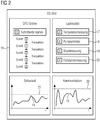
- the expansion module 11 also transmits the current tax load to the OS client 3 via the OS interface 12, whereby the current control load of the automation device 1 is displayed to the user in addition to the current communication load becomes.
- the expansion module 11 binds the control module 10s into the control program 10, if the user enables this control module 10s for connecting the real field device 9r to the bus.
- the activation by the user takes place by means of a suitable input on the OS client 3, on which the user is shown the tax load limit in addition to the current tax load.
- the real field device 9r corresponding to the virtual field device 5v can be connected to the bus 8.
- the expansion module 11 blocks the control module 10s, which means that it is not integrated into the control program 10.
- the existing automation device 1 cannot be expanded to include this field device.
- the automation device can only be expanded if it is expanded to include a further automation device, so that the control load can be distributed over several automation devices.
- the automation device 1 can be expanded to include further field devices in the manner described. For this purpose, a further one of the virtual field devices is first switched on and a check is again made as to whether the automation device 1 can be expanded by a further real field device corresponding to this virtual field device. To this end, the user is always shown what the current communication and control load is, so that the automation device 1 can be brought up to the communication and control load limits, as it were, in “homeopathic doses”.
Landscapes
- Engineering & Computer Science (AREA)
- Physics & Mathematics (AREA)
- General Physics & Mathematics (AREA)
- Automation & Control Theory (AREA)
- General Engineering & Computer Science (AREA)
- Geometry (AREA)
- Theoretical Computer Science (AREA)
- Quality & Reliability (AREA)
- Manufacturing & Machinery (AREA)
- Computer Hardware Design (AREA)
- Evolutionary Computation (AREA)
- Pure & Applied Mathematics (AREA)
- Mathematical Optimization (AREA)
- Mathematical Analysis (AREA)
- Computational Mathematics (AREA)
- Programmable Controllers (AREA)
- Control By Computers (AREA)
Description
Die Erfindung betrifft ein Verfahren zum Erweitern einer Automatisierungseinrichtung mit einem Feldgerät, wobei die Automatisierungseinrichtung zumindest ein Automatisierungsgerät und zumindest ein Feldgerät aufweist, die an eine Kommunikationsverbindung angeschlossen sind, und wobei die Automatisierungseinrichtung ferner durch ein Engineeringverfahren zur Lösung einer Automatisierungsaufgabe derart projektiert ist, dass das zumindest eine Automatisierungsgerät während einer Prozesssteuerung ein projektiertes Steuerprogramm verarbeitet, das eine Vielzahl von Steuer-Bausteinen umfasst. Darüber hinaus betrifft die Erfindung eine Automatisierungseinrichtung gemäß dem Oberbegriff des Anspruchs 3 zur Durchführung des Verfahrens.The invention relates to a method for expanding an automation device with a field device, wherein the automation device has at least one automation device and at least one field device that are connected to a communication link, and wherein the automation device is further configured by an engineering method for solving an automation task in such a way that the At least one automation device processes a configured control program during process control, which control program comprises a plurality of control modules. The invention also relates to an automation device according to the preamble of
Aus dem
Eine derartige Anlage ist gewöhnlich keine statische Produktionsstätte, die einmal geplant, errichtet und in Betrieb genommen und anschließend nicht mehr verändert wird. Vielmehr unterliegt die Anlage ständigen Änderungen und Anpassungen, um die Produktion zu optimieren und zu erweitern. Dazu ist es gewöhnlich erforderlich, auch neue prozessnahe Automatisierungskomponenten in Form von weiteren Feldgeräten in die Automatisierungseinrichtung einzubinden. Diese Einbindung erfolgt derart, dass diese Feldgeräte über einen Bus mit dem Automatisierungsgerät bzw. mit einer Steuerung der Automatisierungseinrichtung kommunikativ verbunden werden und das Steuerprogramm bzw. die Automatisierungssoftware mit entsprechenden Steuerbausteinen zum Ansteuern dieser Feldgeräte entsprechend ergänzt wird. Im Rahmen einer derartigen Erweiterung ist es wünschenswert, dass die Produktion - z. B. die Produktion zur Herstellung von Kunstharz, Farbstoffen oder Düngemitteln - nicht störend beeinflusst wird. Dies bedeutet, dass die bereits bestehenden Automatisierungskomponenten der Automatisierungseinrichtung während der Inbetriebsetzung bzw. während der Einbindung der neuen Feldgeräte ohne wesentliche Einschränkung des Produktionsbetriebs weiterlaufen muss; denn jede Einschränkung oder sogar ein Produktionsstopp (Anlagenstillstand) führt gewöhnlich zu finanziellen Einbußen.From the
Such a plant is usually not a static production facility that is once planned, built and commissioned and then not changed again. Rather, the system is subject to constant changes and adjustments in order to optimize and expand production. For this, it is usually necessary to also integrate new process-related automation components in the form of further field devices into the automation device. This integration takes place in such a way that these field devices are connected to the automation device or to a controller of the automation device via a bus be communicatively connected and the control program or the automation software is supplemented accordingly with appropriate control modules for controlling these field devices. As part of such an expansion, it is desirable that the production - z. B. the production for the production of synthetic resin, dyes or fertilizers - is not affected. This means that the already existing automation components of the automation device must continue to run during the commissioning or during the integration of the new field devices without significant restriction of the production operation; because every restriction or even a production stop (plant standstill) usually leads to financial losses.
Ob die vorhanden Leistungsreserven des Automatisierungsgerätes oder der Kommunikationsverbindung ausreichen, um die neuen Feldgeräte ohne eine derartige Einschränkung in Betrieb setzen zu können, zeigt sich während deren Inbetriebnahme. Nicht selten führt diese Inbetriebnahme zu einem Stillstand der Anlage und damit zu einem Produktionsstopp, weil die Leistungsreserven nicht ausreichen, um Aufgaben zu vorgegebenen Verarbeitungszyklen des Automatisierungsgerätes oder im Rahmen der vorgegebenen Kommunikationszyklen des Kommunikationsnetzes der Automatisierungseinrichtung zu bewerkstelligen.Whether the existing power reserves of the automation device or the communication connection are sufficient to be able to put the new field devices into operation without such a restriction is shown during their commissioning. This commissioning often leads to a standstill of the system and thus to a production stop, because the power reserves are insufficient to accomplish tasks in the specified processing cycles of the automation device or within the framework of the specified communication cycles of the communication network of the automation device.
Um die Störanfälligkeit während der Inbetriebnahme der neuen Feldgeräte zu verringern, können im Rahmen der Projektierung von Erweiterungen der Automatisierungseinrichtung die Leistungsreserven der Steuerung und des Kommunikationsnetzes abgeschätzt werden. Hier spielen neben klaren Fakten, wie die maximale Zahl der Automatisierungskomponenten bzw. Busteilnehmer und der maximale Umfang der Steuerungssoftware bezogen auf die Speicherbelegung und die Verarbeitungslaufzeit bzw. den Verarbeitungszyklus, vor allem auch die langjähre Erfahrung der Projekteure eine bedeutende Rolle. Aufgrund dieser Abschätzungen bzw. Annahmen erfolgt die Inbetriebnahme nie ohne Restrisiko. Dieses Restrisiko kann vermindert werden, indem eine entsprechende "Schatten-Anlage bzw. - Automatisierungseinrichtung" aufgebaut wird, um die Funktionsweise und die Inbetriebnahme vorab zu testen. Dies bedeutet erhebliche Material- und Personalkosten, wobei ferner eine Schatten-Anlage für die Vorbereitung der Erweiterung in der Regel auch nur eine Nachbildung der Anlage und nie eine exakte Kopie repräsentiert.In order to reduce the susceptibility to failure during commissioning of the new field devices, the power reserves of the controller and the communication network can be estimated as part of the project planning of extensions to the automation device. In addition to clear facts, such as the maximum number of automation components or bus participants and the maximum scope of the control software in relation to the memory allocation and the processing time or the processing cycle, the many years of experience of the project engineers play an important role. Based on these estimates or assumptions, commissioning never takes place without a residual risk. This residual risk can be reduced by installing a corresponding "shadow system or automation device" is set up to test the functionality and commissioning in advance. This means considerable material and personnel costs, with a shadow system for the preparation of the expansion also usually only representing a replica of the system and never an exact copy.
Der Erfindung liegt daher die Aufgabe zugrunde, ein Verfahren entsprechend Anspruch 1 auszuführen. Darüber hinaus ist eine Automatisierungseinrichtung entsprechend Anspruch 2 auszuführen. Diese Aufgabe wird im Hinblick auf das Verfahren durch die im kennzeichenenden Teil des Anspruchs 1 angegebenen, bezüglich der Automatisierungseinrichtung durch die im kennzeichnenden Teil des Anspruchs 2 angegebenen Maßnahmen gelöst.The invention is therefore based on the object of carrying out a method according to
Vorteilhaft ist, dass ein sicherer und stufenweise steigerungsfähiger "Stresstest" für die Erweiterung der Automatisierungseinrichtung möglich ist, wobei auf eine "Schatten-Automatisierungseinrichtung" verzichtet werden kann und sichergestellt ist, dass ein Stillstand der Automatisierungseinrichtung und damit ein Produktionsstopp vermieden wird. Ein Anwender kann mehrere virtuelle Feldgeräte projektieren, die jeweils ein reales Feldgerät repräsentieren sowie diese realen Feldgeräte emulieren. Diese virtuellen Feldgeräte werden nacheinander der Automatisierungseinrichtung zugeschaltet bzw. aktiviert, wobei nach jedem Zuschalten eines der virtuellen Feldgeräte zunächst die aktuelle Kommunikations-Belastung und die aktuelle Steuer-Belastung der Automatisierungseinrichtung erfasst werden. Für den Fall, dass die aktuelle Kommunikations-Belastung eine Kommunikations-Lastgrenze und die aktuelle Steuer-Belastung eine Steuer-Lastgrenze nicht überschreiten, kann der Anwender die Automatisierungseinrichtung schließlich um das reale Feldgerät erweitern, welches durch das zugeschaltete virtuelle Feldgerät emuliert wurde.It is advantageous that a more reliable and gradually increasing "stress test" is possible for the expansion of the automation device, whereby a "shadow automation device" can be dispensed with and it is ensured that a standstill of the automation device and thus a production stop is avoided. A user can configure several virtual field devices, each representing a real field device and emulating these real field devices. These virtual field devices are connected to the automation device or activated one after the other, with the current communication load and the current control load of the automation device being recorded after each connection of one of the virtual field devices. In the event that the current communication load has a communication load limit and If the current tax load does not exceed a control load limit, the user can finally expand the automation device to include the real field device that was emulated by the connected virtual field device.
Anschließend kann ein weiteres der virtuellen Feldgeräte zugeschaltet werden um wiederum zu prüfen, ob die Automatisierungseinrichtung um ein diesem virtuellen Feldgerät entsprechendes reales Feldgerät erweitert werden kann. Dem Anwender wird stets angezeigt, wie hoch die aktuelle Kommunikationsund Steuer-Belastung ist, sodass die Automatisierungseinrichtung quasi in "homöopathischen Dosen" (durch Hinzufügen jeweils eines weiteren virtuellen Feldgerätes) an die Kommunikations- und Steuer-Lastgrenzen herangeführt werden kann.A further one of the virtual field devices can then be connected in order to again check whether the automation device can be expanded by a real field device corresponding to this virtual field device. The user is always shown how high the current communication and control load is, so that the automation device can be brought up to the communication and control load limits in "homeopathic doses" (by adding another virtual field device).
Falls allerdings die aktuelle Kommunikations- oder die aktuelle Steuer-Belastung die jeweilige Lastgrenze überschreitet, nachdem ein virtuelles Feldgerät zugeschaltet wurde, ist eine Erweiterung der bestehenden Automatisierungseinrichtung mit dem realen Feldgerät, das durch dieses zugeschaltete virtuelle Feldgerät emuliert wurde, nicht möglich. In diesem Fall muss zunächst die bestehende Automatisierungseinrichtung mit einem oder mehreren Automatisierungsgeräten und/oder Kommunikationsmitteln erweitert werden.However, if the current communication load or the current control load exceeds the respective load limit after a virtual field device has been connected, it is not possible to expand the existing automation device with the real field device that was emulated by this connected virtual field device. In this case, the existing automation device must first be expanded with one or more automation devices and / or communication means.
In einer Ausgestaltung der Erfindung wird eine Remotebearbeitung ermöglicht. Dem Anwender wird die aktuelle Kommunikationsund die aktuelle Steuer-Belastung auf einem Bedien- und Beobachtunggerät angezeigt, wobei der Anwender über dieses Gerät den Steuer-Baustein freischalten kann, falls die aktuelle Kommunikations- und die aktuelle Steuer-Belastung die jeweilige Lastgrenze nicht überschreiten.
Anhand der Zeichnung, in der ein Ausführungsbeispiel der Erfindung veranschaulicht ist, werden im Folgenden die Erfindung, deren Ausgestaltungen sowie Vorteile näher erläutert.
Es zeigen in einer vereinfachten Darstellung
-
Figur 1 -
Figur 2
With the aid of the drawing, in which an exemplary embodiment of the invention is illustrated, the invention, its configurations and advantages are explained in more detail below.
It show in a simplified representation
-
Figure 1 Components of an automation device and -
Figure 2 the display of a communication and control load on an operating and monitoring device.
In
Ein an sich bekanntes Engineering bzw. Engineeringverfahren zur Erstellung eines Steuerprogramms basiert auf einem auf dem Engineering-System ablauffähigen Continuous Function Chart (CFC)- und auf Sequential Continuous Function Chart (SFC)-Editoren.
Ein Anwender erstellt mittels des CFC-Editors aus vorgefertigten Bausteinen nach Maßgabe der zu lösenden Automatisierungsaufgabe grafisch das Steuerprogramm für das Automatisierungsgerät 2 und wählt dazu die Bausteine, z. B. einen Regler- oder Zähler-Baustein, aus einem verfügbaren Bausteinvorrat aus, platziert die Bausteine z. B. per Drag&Drop in einem Funktionsplan (z. B. CFC-Plan) und verschaltet diese per Mausklick miteinander. Nachdem der Anwender alle Funktionen im Funktionsplan erstellt hat, erzeugt das Engineering-System durch das Automatisierungsgerät 2 lesbare CFC-Funktionen, die in dieses Automatisierungsgerät 2 geladen und dort im Rahmen der Prozesssteuerung zur Lösung der Automatisierungsaufgabe verarbeitet werden.
Mittels des SFC-Editors erstellt der Anwender ferner in gewohnter Art und Weise grafisch eine Ablaufsteuerung (SCF), die gewöhnlich eine Vielzahl von Schrittketten umfasst, die wiederum eine Vielzahl von Rezeptelementen sowie Transitionen aufweisen, z. B. Rezeptelemente in Form von Rezeptoperationen oder Rezeptfunktionen, z. B. Dosieren, Heizen oder Rühren. Aus dieser Ablaufsteuerung erzeugt das Engineering-System durch das Automatisierungsgerät 2 verarbeitbare (SFC-) Objekte, die das Engineering-System compiliert und in das Automatisierungsgerät 2 lädt.
Während der Prozesssteuerung - also im RUN-Betrieb des Automatisierungsgeräts 2 - wird die Interaktion und Verknüpfung zwischen den (SFC-) Objekten und den CFC-Funktionen über Prozesswerte und Steuersignale (SFC-Daten) bewerkstelligt, wobei ferner einem Operator die Schrittkette auf dem OS-Client 3 dargestellt wird. Dadurch kann der Operator beobachten, welches Rezeptelement der Schrittketten gerade verarbeitet wird. Jedem Schritt der Schrittkette ist eine bestimmte Aktion zugeordnet, welche die CFC-Funktionen parametrieren und aktivieren, wobei dazu entsprechende Steuersignale gesetzt werden. Die Prozesswerte umfassen Prozesseingangswerte (Istwerte), welche Sensoren dem Automatisierungsgerät 2 zuführen und die das Automatisierungsgerät 2 dem OS-Server zur Hinterlegung in einem Prozessabbild übermittelt, sowie Prozessausgangswerte (Sollwerte), die der OS-Server dem Automatisierungsgerät 2 zur Ansteuerung der Aktoren zuführt.An engineering or engineering method known per se for creating a control program is based on a continuous function chart (CFC) that can run on the engineering system and on sequential continuous function chart (SFC) editors.
Using the CFC editor, a user graphically creates the control program for the
Using the SFC editor, the user also creates a process control (SCF) graphically in the usual way, which usually comprises a large number of step chains, which in turn have a large number of recipe elements and transitions, e.g. B. recipe elements in the form of recipe operations or recipe functions, e.g. B. dosing, heating or stirring. From this sequence control, the engineering system generates (SFC) objects that can be processed by the
During process control - i.e. in RUN mode of the automation device 2 - the interaction and linkage between the (SFC) objects and the CFC functions is implemented via process values and control signals (SFC data), with an operator also managing the sequencer on the
Im vorliegenden Ausführungsbeispiel wird angenommen, dass im Automatisierungsgerät 2 ein projektiertes Steuerprogramm 10 (SFCs, CFCs) hinterlegt ist und das Automatisierungsgerät 2 dieses Steuerprogramm 10 zur Prozesssteuerung gerade verarbeitet. Um während dieser Prozesssteuerung die Automatisierungseinrichtung 1 um ein oder mehrere reale Feldgeräte 9r - ohne störende Einflüsse auf die Prozesssteuerung - erweitern zu können, sind im Kommunikationsteilnehmer 5 für jedes dieser Feldgeräte 9r ein durch das Engineering-System projektiertes virtuelles Feldgerät 5v und ferner im Automatisierungsgerät 2 ein Erweiterungs-Baustein 11 hinterlegt, welcher für jedes virtuelle Feldgerät 5v einen projektierten Steuer-Baustein 10s zum Ansteuern des jeweiligen virtuellen Feldgerätes 5v aufweist. Diese virtuellen Feldgeräte 5v repräsentieren die realen Feldgeräte und sind dazu ausgebildet, die realen Feldgeräte zu emulieren. Der Erweiterungs-Baustein 11 ist ferner mit einer OS-Schnittstelle 12 zum Austauschen von Informationen zwischen dem Erweiterungs-Baustein 11 und dem OS-Client 3 versehen, wobei einerseits der Anwender durch eine entsprechende Eingabe am OS-Client 3 die Erweiterung der Automatisierungseinrichtung 1 einleiten kann und andererseits der OS-Client 3 dem Anwender die aktuelle Kommunikations- und Steuer-Belastung anzeigt. Darüber hinaus kann der Anwender durch eine weitere Eingabe am OS-Client 3 die jeweiligen Steuer-Bausteine 10s freischalten, damit der Erweiterungs-Baustein 11 in Abhängigkeit der aktuellen Kommunikations- und Steuer-Belastung die jeweiligen Steuer-Bausteine 10s in das Steuerprogramm 10 einbindet.
Die Erweiterung der Automatisierungseinrichtung 1 erfolgt in der Art und Weise, dass ein Anwender zunächst eines der projektierten virtuellen Feldgeräte 5v auswählt, indem er z. B. ein diesem Feldgerät 5v zugeordnetes und auf dem OS-Client 3 dargestelltes Icon anwählt bzw. markiert. Aufgrund dieser Auswahl kommuniziert ein Ausführungsteil 13 des Erweiterungs-Bausteins 11 mit diesem virtuellen, im Kommunikationsteilnehmer 5 hinterlegten Feldgerät 5v, wobei der Kommunikationsteilnehmer 5 die aktuelle Kommunikations-Belastung ermittelt und abspeichert. Diese Kommunikations-Belastung umfasst die durch die Kommunikation zwischen dem virtuellen Feldgerät 5v und dem Ausführungsteil 13 und die durch die Kommunikation der Prozesssteuerung verursachte Belastung. Unter der Formulierung "durch die Kommunikation der Prozesssteuerung verursachte Belastung" wird die Belastung der Kommunikationsverbindung 7 während der Verarbeitung des Steuerprogramms 10 verstanden, während dessen das Automatisierungsgerät 2 mit den realen Feldgeräten 9 kommuniziert. Dadurch, dass der Kommunikationsteilnehmer 5 die Kommunikations-Belastung erfasst, wird das Automatisierungsgerät 2 nicht zusätzlich belastet. Der Erweiterungs-Baustein 11 liest die im Kommunikationsteilnehmer 5 abgespeicherte aktuelle Kommunikations-Belastung aus und übermittelt diese über die OS-Schnittstelle 12 dem OS-Client 3, welcher die aktuelle Kommunikations-Belastung dem Anwender anzeigt. Für den Fall, dass diese aktuelle Kommunikations-Belastung eine vorgegebene Kommunikations-Lastgrenze erreicht oder überschreitet, wird der Anwender mittels einer Anzeige bzw. Meldung auf dem OS-Client darauf hingewiesen, dass eine Erweiterung der bestehenden Automatisierungseinrichtung 1 mit dem dem virtuellen Feldgerät 5v entsprechenden realen Feldgerät 9r nicht möglich ist, es sei denn, die Automatisierungseinrichtung 1 wird um ein weiteres Kommunikationsmittel (Busverbindungen, Switches, ...) erweitert.
Für den Fall dagegen, dass diese aktuelle Kommunikations-Belastung die vorgegebene Kommunikations-Lastgrenze nicht überschreitet, aktiviert der Ausführungsteil 13 automatisch den Steuer-Baustein 10s zum Ansteuern des ausgewählten virtuellen Feldgerätes 5v. Während dieser Ansteuerung erfasst der Erweiterungs-Bausteins 11 die Steuer-Belastung des Automatisierungsgerätes 2, welche die durch die Prozesssteuerung und die durch die Verarbeitung des Steuer-Bausteins 10s zum Ansteuern des ausgewählten virtuellen Feldgerätes 5v verursachte Belastung umfasst, wobei diese beiden Belastungen sich auf den Verarbeitungszyklus des Automatisierungsgerätes 2 auswirken. Dabei wird unter der Formulierung "die durch die Prozesssteuerung verursachte Belastung" die Belastung des Automatisierungsgerätes 2 während der Verarbeitung des Steuerprogramms 10 verstanden. Zur Anzeige der aktuellen Steuer-Belastung übermittelt der Erweiterungs-Baustein 11 die aktuelle Steuer-Belastung ebenfalls über die OS-Schnittstelle 12 dem OS-Client 3, wodurch dem Anwender neben der aktuellen Kommunikations-Belastung auch die aktuelle Steuer-Belastung der Automatisierungseinrichtung 1 angezeigt wird. Für den Fall, dass diese aktuelle Steuer-Belastung eine vorgegebene Steuer-Lastgrenze nicht erreicht oder überschreitet, bindet der Erweiterungs-Baustein 11 den Steuer-Baustein 10s in das Steuerprogramm 10 ein, falls der Anwender diesen Steuer-Baustein 10s zum Anschließen des realen Feldgerätes 9r an den Bus freischaltet. Die Freischaltung durch den Anwender erfolgt mittels einer geeigneten Eingabe am OS-Client 3, auf welchem dem Anwender neben der aktuellen Steuer-Belastung die Steuer-Lastgrenze angezeigt wird. Nachdem der Anwender den Steuer-Baustein 10s freigeschaltet hat, kann das dem virtuellen Feldgerät 5v entsprechende reale Feldgerät 9r an den Bus 8 angeschlossen werden. Für den Fall, dass die aktuelle Steuer-Belastung allerdings die vorgegebene Steuer-Lastgrenze erreicht oder überschreitet, blockiert der Erweiterungs-Baustein 11 den Steuer-Baustein 10s, was bedeutet, dass dieser nicht in das Steuerprogramm 10 eingebunden wird. Auch in diesem Fall wird dem Anwender angezeigt, dass die bestehende Automatisierungseinrichtung 1 um dieses Feldgerät nicht erweitert werden kann. Eine Erweiterung der Automatisierungseinrichtung ist nur dann möglich, wenn diese um ein weiteres Automatisierungsgerät erweitert wird, wodurch die Steuer-Belastung auf mehrere Automatisierungsgeräte verteilt werden kann.In the present exemplary embodiment, it is assumed that a configured control program 10 (SFCs, CFCs) is stored in the
The
In contrast, in the event that this current communication load does not exceed the specified communication load limit, the
In der beschrieben Art und Weise kann die Automatisierungseinrichtung 1 um weitere Feldgeräte erweitert werden. Dazu wird zunächst ein weiteres der virtuellen Feldgeräte zugeschaltet und wiederum geprüft, ob die Automatisierungseinrichtung 1 um ein weiteres diesem virtuellen Feldgerät entsprechendes reales Feldgerät erweitert werden kann. Dem Anwender wird dazu stets angezeigt, wie die aktuelle Kommunikations- und Steuer-Belastung ist, sodass die Automatisierungseinrichtung 1 quasi in "homöopathischen Dosen" an die Kommunikations-und Steuer-Lastgrenzen herangeführt werden kann.The
Im Folgenden wird auf
Claims (2)
- Method for expanding an automation facility (1) with at least one field device (9), wherein the automation facility (1)- has at least one automation device (2) and at least one field device (9), which are connected to a communication link (7, 8), and- is planned into a project by an engineering method for solving an automation problem such that the at least one automation device (2) processes a projected control program (10) that comprises a plurality of control modules when controlling a process,
characterised in that- at least one virtual field device (5v) representing a real field device (9r) and a control module (10s) for controlling the virtual field device (5v) are planned into the project,- the current communication load is determined by the communication user (5), which communication load comprises the load caused by the communication of the process control and the load caused by the communication between the virtual field device (5v) and an expansion module (11) of the at least one automation device (2) planned into the project, wherein the expansion module (11) comprises the control module (10s) for controlling the virtual field device (5v) and has an interface (12) for exchange of information between the expansion module (11) and a control and monitoring device (3),- the current control load of the at least one automation device (2) is detected by the expansion module (11), which comprises the load caused by the process control and the load caused by the processing of the control module (10s) planned into the project, and- the control module (10s) planned into the project is linked into the control program (10) as a function of the current communication load and the current control load, if this control module (10s) is enabled by a user for connecting the real field device (9r) to the bus (7, 8) via the control and monitoring device (3), wherein the current communication and control load is displayed to the user on the operator control and monitoring device (3). - Automation facility, which- has at least one automation device (2) and at least one field device (9), which are connected to a communication link (7, 8),- is planned into a project by an engineering method for solving an automation problem such that the at least one automation device (2), when controlling a process, processes a control program (10) planned into the project that comprises a plurality of control modules,
characterised in that- at least one projected virtual field device (5v), which represents a real field device (9r) is stored in a projected communication user (5) connected to the communication link (7, 8),- the communication user (5) determines the current communication load, which comprises the load caused by the communication of the process control and the load caused by the communication between the virtual field device (5v) and a projected expansion module (11) of the at least one automation device (2),
wherein the expansion module (11) has an interface (12) for exchange of information between the expansion module (11) and a control and monitoring device (3),- a projected control module (10s) for controlling the virtual field device (5v) is stored in the expansion module (11),- the expansion module (11) detects the current control load of the at least one automation device (2), which comprises the load caused by the process control and the load caused by the processing of the control module (10s), and- the expansion module (11) is embodied to link the projected control module (10s) into the control program (10) as a function of the current communication load and the current control load, if a user enables this control module (10s) for connecting the real field device (9r) to the bus (7, 8) via the control and monitoring device (3), wherein the current communication and control load is displayed to the user on the operator control and monitoring device (3).
Priority Applications (3)
| Application Number | Priority Date | Filing Date | Title |
|---|---|---|---|
| EP15163409.4A EP3082001B1 (en) | 2015-04-13 | 2015-04-13 | Method for expanding an automation device using a virtual field device and automation device |
| US15/093,000 US9886028B2 (en) | 2015-04-13 | 2016-04-07 | Automation facility and method for expanding the automation facility with at least one field device |
| CN201610224048.XA CN106054762B (en) | 2015-04-13 | 2016-04-12 | Method for extending automation equipment and automation equipment |
Applications Claiming Priority (1)
| Application Number | Priority Date | Filing Date | Title |
|---|---|---|---|
| EP15163409.4A EP3082001B1 (en) | 2015-04-13 | 2015-04-13 | Method for expanding an automation device using a virtual field device and automation device |
Publications (2)
| Publication Number | Publication Date |
|---|---|
| EP3082001A1 EP3082001A1 (en) | 2016-10-19 |
| EP3082001B1 true EP3082001B1 (en) | 2020-09-09 |
Family
ID=53002501
Family Applications (1)
| Application Number | Title | Priority Date | Filing Date |
|---|---|---|---|
| EP15163409.4A Active EP3082001B1 (en) | 2015-04-13 | 2015-04-13 | Method for expanding an automation device using a virtual field device and automation device |
Country Status (3)
| Country | Link |
|---|---|
| US (1) | US9886028B2 (en) |
| EP (1) | EP3082001B1 (en) |
| CN (1) | CN106054762B (en) |
Families Citing this family (3)
| Publication number | Priority date | Publication date | Assignee | Title |
|---|---|---|---|---|
| US10934764B2 (en) * | 2016-09-08 | 2021-03-02 | Magna Closures Inc. | Radar detection system for non-contact human activation of powered closure member |
| DE102019204480A1 (en) * | 2019-03-29 | 2020-10-01 | Siemens Aktiengesellschaft | Method for engineering an automation system for controlling a process in a technical installation and automation system |
| DE102022105472A1 (en) | 2022-03-09 | 2023-09-14 | Endress+Hauser SE+Co. KG | Automation technology system |
Family Cites Families (9)
| Publication number | Priority date | Publication date | Assignee | Title |
|---|---|---|---|---|
| DE10245176A1 (en) * | 2002-09-26 | 2004-04-01 | Endress + Hauser Process Solutions Ag | Process for simulating a field device in a network of process automation technology |
| DE102004039886A1 (en) * | 2004-08-17 | 2006-03-09 | Endress + Hauser Flowtec Ag | Method for operating a field device of automation technology |
| US20070078696A1 (en) * | 2005-08-30 | 2007-04-05 | Invensys Systems Inc. | Integrating high level enterprise-level decision- making into real-time process control |
| DE102006059819A1 (en) * | 2006-12-11 | 2008-06-19 | Index-Werke Gmbh & Co. Kg Hahn & Tessky | working machine |
| DE102007062395B4 (en) * | 2007-12-20 | 2019-08-08 | Endress + Hauser Flowtec Ag | Method for parameterizing a field device of process automation technology |
| DE102010029952B4 (en) * | 2010-06-10 | 2019-06-27 | Endress + Hauser Process Solutions Ag | Method for integrating at least one field device in a network of automation technology |
| CN103238143B (en) * | 2010-09-27 | 2016-11-16 | 费希尔-罗斯蒙特系统公司 | Method and apparatus for virtualization process control system |
| DE102010053485A1 (en) * | 2010-12-04 | 2012-06-06 | Robert Bosch Gmbh | Method for operating a work machine and work machine with virtual automation |
| CN103793278B (en) * | 2013-09-30 | 2017-04-26 | 中国电子设备系统工程公司研究所 | Automatic resource adjusting method on basis of operation and maintenance rules of virtual device |
-
2015
- 2015-04-13 EP EP15163409.4A patent/EP3082001B1/en active Active
-
2016
- 2016-04-07 US US15/093,000 patent/US9886028B2/en active Active
- 2016-04-12 CN CN201610224048.XA patent/CN106054762B/en active Active
Non-Patent Citations (1)
| Title |
|---|
| None * |
Also Published As
| Publication number | Publication date |
|---|---|
| US9886028B2 (en) | 2018-02-06 |
| CN106054762B (en) | 2018-11-13 |
| CN106054762A (en) | 2016-10-26 |
| EP3082001A1 (en) | 2016-10-19 |
| US20170023932A1 (en) | 2017-01-26 |
Similar Documents
| Publication | Publication Date | Title |
|---|---|---|
| EP2453326B1 (en) | Method and system for operating an automated machine | |
| EP3523703B1 (en) | Method for updating software in cloud gateways, computer program with an implementation of the method and processing unit for executing the method | |
| DE102007026678A1 (en) | Method for exchanging a defective field device for a new field device in a system communicating via a digital field bus, in particular an automation system | |
| DE102013100465A1 (en) | Microprocessor-controlled control device for an injection molding plant | |
| EP3273315B1 (en) | Platform for further use of existing software for controlling industrial field devices | |
| EP3082001B1 (en) | Method for expanding an automation device using a virtual field device and automation device | |
| EP2732347B1 (en) | Method and system for the dynamic distribution of program functions in distributed control systems | |
| DE102006035889A1 (en) | System and method for automatically installing and maintaining hardware and software in a distributed computer system | |
| EP3067768B1 (en) | Automation device and operator system | |
| WO2005022286A2 (en) | Method for graphically planning the control of a technical installation involving the integrated planning of control units including a project planning system and a computer program product | |
| WO2014161986A1 (en) | Control and data transfer system for redundant process control and method for firmware updating | |
| EP1950635B1 (en) | Method for operating an automation system | |
| EP3457234A1 (en) | Method and data processing device for providing information in the form of computer code to a process module with the assistance of a computer, and computer program product for carrying out the method | |
| DE102014217561B4 (en) | Method and arrangement for testing a multimedia device | |
| EP2811349A1 (en) | Method for operating an automation system | |
| EP1947536B1 (en) | Configuration update method for a working automation device | |
| WO2013020844A1 (en) | Open-loop and/or closed-loop control device | |
| EP3805878B1 (en) | Method for visualizing display data on a data display system and a data display system for visualizing display data | |
| BE1026752B1 (en) | Device and method for iterative and interactive project planning from an I / O station for an automation control | |
| WO2023117938A1 (en) | Parameterisation and/or configuration technique for a device based on a programmable logic controller | |
| EP3133448B1 (en) | Method and device for programming and controlling hydraulic devices | |
| EP3035137B1 (en) | Regulator module for use in an industrial automation assembly | |
| EP3128381A1 (en) | Engineering system and method for operating same | |
| EP2913728B1 (en) | Method for operating an automation device and automation device | |
| EP4198657A1 (en) | Method for operating a wind turbine and wind turbine control device for executing the method |
Legal Events
| Date | Code | Title | Description |
|---|---|---|---|
| PUAI | Public reference made under article 153(3) epc to a published international application that has entered the european phase |
Free format text: ORIGINAL CODE: 0009012 |
|
| AK | Designated contracting states |
Kind code of ref document: A1 Designated state(s): AL AT BE BG CH CY CZ DE DK EE ES FI FR GB GR HR HU IE IS IT LI LT LU LV MC MK MT NL NO PL PT RO RS SE SI SK SM TR |
|
| AX | Request for extension of the european patent |
Extension state: BA ME |
|
| STAA | Information on the status of an ep patent application or granted ep patent |
Free format text: STATUS: REQUEST FOR EXAMINATION WAS MADE |
|
| 17P | Request for examination filed |
Effective date: 20170418 |
|
| RBV | Designated contracting states (corrected) |
Designated state(s): AL AT BE BG CH CY CZ DE DK EE ES FI FR GB GR HR HU IE IS IT LI LT LU LV MC MK MT NL NO PL PT RO RS SE SI SK SM TR |
|
| RAP1 | Party data changed (applicant data changed or rights of an application transferred) |
Owner name: SIEMENS AKTIENGESELLSCHAFT |
|
| STAA | Information on the status of an ep patent application or granted ep patent |
Free format text: STATUS: EXAMINATION IS IN PROGRESS |
|
| 17Q | First examination report despatched |
Effective date: 20180420 |
|
| REG | Reference to a national code |
Ref country code: DE Ref legal event code: R079 Ref document number: 502015013408 Country of ref document: DE Free format text: PREVIOUS MAIN CLASS: G05B0019042000 Ipc: H04L0012260000 |
|
| GRAP | Despatch of communication of intention to grant a patent |
Free format text: ORIGINAL CODE: EPIDOSNIGR1 |
|
| STAA | Information on the status of an ep patent application or granted ep patent |
Free format text: STATUS: GRANT OF PATENT IS INTENDED |
|
| RIC1 | Information provided on ipc code assigned before grant |
Ipc: H04L 12/26 20060101AFI20200603BHEP |
|
| INTG | Intention to grant announced |
Effective date: 20200618 |
|
| GRAS | Grant fee paid |
Free format text: ORIGINAL CODE: EPIDOSNIGR3 |
|
| GRAA | (expected) grant |
Free format text: ORIGINAL CODE: 0009210 |
|
| STAA | Information on the status of an ep patent application or granted ep patent |
Free format text: STATUS: THE PATENT HAS BEEN GRANTED |
|
| AK | Designated contracting states |
Kind code of ref document: B1 Designated state(s): AL AT BE BG CH CY CZ DE DK EE ES FI FR GB GR HR HU IE IS IT LI LT LU LV MC MK MT NL NO PL PT RO RS SE SI SK SM TR |
|
| REG | Reference to a national code |
Ref country code: GB Ref legal event code: FG4D Free format text: NOT ENGLISH |
|
| REG | Reference to a national code |
Ref country code: AT Ref legal event code: REF Ref document number: 1312925 Country of ref document: AT Kind code of ref document: T Effective date: 20200915 Ref country code: CH Ref legal event code: EP |
|
| REG | Reference to a national code |
Ref country code: DE Ref legal event code: R096 Ref document number: 502015013408 Country of ref document: DE |
|
| REG | Reference to a national code |
Ref country code: IE Ref legal event code: FG4D Free format text: LANGUAGE OF EP DOCUMENT: GERMAN |
|
| REG | Reference to a national code |
Ref country code: LT Ref legal event code: MG4D |
|
| PG25 | Lapsed in a contracting state [announced via postgrant information from national office to epo] |
Ref country code: LT Free format text: LAPSE BECAUSE OF FAILURE TO SUBMIT A TRANSLATION OF THE DESCRIPTION OR TO PAY THE FEE WITHIN THE PRESCRIBED TIME-LIMIT Effective date: 20200909 Ref country code: HR Free format text: LAPSE BECAUSE OF FAILURE TO SUBMIT A TRANSLATION OF THE DESCRIPTION OR TO PAY THE FEE WITHIN THE PRESCRIBED TIME-LIMIT Effective date: 20200909 Ref country code: GR Free format text: LAPSE BECAUSE OF FAILURE TO SUBMIT A TRANSLATION OF THE DESCRIPTION OR TO PAY THE FEE WITHIN THE PRESCRIBED TIME-LIMIT Effective date: 20201210 Ref country code: BG Free format text: LAPSE BECAUSE OF FAILURE TO SUBMIT A TRANSLATION OF THE DESCRIPTION OR TO PAY THE FEE WITHIN THE PRESCRIBED TIME-LIMIT Effective date: 20201209 Ref country code: NO Free format text: LAPSE BECAUSE OF FAILURE TO SUBMIT A TRANSLATION OF THE DESCRIPTION OR TO PAY THE FEE WITHIN THE PRESCRIBED TIME-LIMIT Effective date: 20201209 Ref country code: SE Free format text: LAPSE BECAUSE OF FAILURE TO SUBMIT A TRANSLATION OF THE DESCRIPTION OR TO PAY THE FEE WITHIN THE PRESCRIBED TIME-LIMIT Effective date: 20200909 Ref country code: FI Free format text: LAPSE BECAUSE OF FAILURE TO SUBMIT A TRANSLATION OF THE DESCRIPTION OR TO PAY THE FEE WITHIN THE PRESCRIBED TIME-LIMIT Effective date: 20200909 |
|
| REG | Reference to a national code |
Ref country code: NL Ref legal event code: MP Effective date: 20200909 |
|
| PG25 | Lapsed in a contracting state [announced via postgrant information from national office to epo] |
Ref country code: PL Free format text: LAPSE BECAUSE OF FAILURE TO SUBMIT A TRANSLATION OF THE DESCRIPTION OR TO PAY THE FEE WITHIN THE PRESCRIBED TIME-LIMIT Effective date: 20200909 Ref country code: LV Free format text: LAPSE BECAUSE OF FAILURE TO SUBMIT A TRANSLATION OF THE DESCRIPTION OR TO PAY THE FEE WITHIN THE PRESCRIBED TIME-LIMIT Effective date: 20200909 Ref country code: RS Free format text: LAPSE BECAUSE OF FAILURE TO SUBMIT A TRANSLATION OF THE DESCRIPTION OR TO PAY THE FEE WITHIN THE PRESCRIBED TIME-LIMIT Effective date: 20200909 |
|
| PG25 | Lapsed in a contracting state [announced via postgrant information from national office to epo] |
Ref country code: CZ Free format text: LAPSE BECAUSE OF FAILURE TO SUBMIT A TRANSLATION OF THE DESCRIPTION OR TO PAY THE FEE WITHIN THE PRESCRIBED TIME-LIMIT Effective date: 20200909 Ref country code: RO Free format text: LAPSE BECAUSE OF FAILURE TO SUBMIT A TRANSLATION OF THE DESCRIPTION OR TO PAY THE FEE WITHIN THE PRESCRIBED TIME-LIMIT Effective date: 20200909 Ref country code: SM Free format text: LAPSE BECAUSE OF FAILURE TO SUBMIT A TRANSLATION OF THE DESCRIPTION OR TO PAY THE FEE WITHIN THE PRESCRIBED TIME-LIMIT Effective date: 20200909 Ref country code: EE Free format text: LAPSE BECAUSE OF FAILURE TO SUBMIT A TRANSLATION OF THE DESCRIPTION OR TO PAY THE FEE WITHIN THE PRESCRIBED TIME-LIMIT Effective date: 20200909 Ref country code: PT Free format text: LAPSE BECAUSE OF FAILURE TO SUBMIT A TRANSLATION OF THE DESCRIPTION OR TO PAY THE FEE WITHIN THE PRESCRIBED TIME-LIMIT Effective date: 20210111 Ref country code: NL Free format text: LAPSE BECAUSE OF FAILURE TO SUBMIT A TRANSLATION OF THE DESCRIPTION OR TO PAY THE FEE WITHIN THE PRESCRIBED TIME-LIMIT Effective date: 20200909 |
|
| PG25 | Lapsed in a contracting state [announced via postgrant information from national office to epo] |
Ref country code: ES Free format text: LAPSE BECAUSE OF FAILURE TO SUBMIT A TRANSLATION OF THE DESCRIPTION OR TO PAY THE FEE WITHIN THE PRESCRIBED TIME-LIMIT Effective date: 20200909 Ref country code: AL Free format text: LAPSE BECAUSE OF FAILURE TO SUBMIT A TRANSLATION OF THE DESCRIPTION OR TO PAY THE FEE WITHIN THE PRESCRIBED TIME-LIMIT Effective date: 20200909 Ref country code: IS Free format text: LAPSE BECAUSE OF FAILURE TO SUBMIT A TRANSLATION OF THE DESCRIPTION OR TO PAY THE FEE WITHIN THE PRESCRIBED TIME-LIMIT Effective date: 20210109 |
|
| REG | Reference to a national code |
Ref country code: DE Ref legal event code: R097 Ref document number: 502015013408 Country of ref document: DE |
|
| PG25 | Lapsed in a contracting state [announced via postgrant information from national office to epo] |
Ref country code: SK Free format text: LAPSE BECAUSE OF FAILURE TO SUBMIT A TRANSLATION OF THE DESCRIPTION OR TO PAY THE FEE WITHIN THE PRESCRIBED TIME-LIMIT Effective date: 20200909 |
|
| PLBE | No opposition filed within time limit |
Free format text: ORIGINAL CODE: 0009261 |
|
| STAA | Information on the status of an ep patent application or granted ep patent |
Free format text: STATUS: NO OPPOSITION FILED WITHIN TIME LIMIT |
|
| 26N | No opposition filed |
Effective date: 20210610 |
|
| PG25 | Lapsed in a contracting state [announced via postgrant information from national office to epo] |
Ref country code: DK Free format text: LAPSE BECAUSE OF FAILURE TO SUBMIT A TRANSLATION OF THE DESCRIPTION OR TO PAY THE FEE WITHIN THE PRESCRIBED TIME-LIMIT Effective date: 20200909 Ref country code: SI Free format text: LAPSE BECAUSE OF FAILURE TO SUBMIT A TRANSLATION OF THE DESCRIPTION OR TO PAY THE FEE WITHIN THE PRESCRIBED TIME-LIMIT Effective date: 20200909 |
|
| REG | Reference to a national code |
Ref country code: DE Ref legal event code: R079 Ref document number: 502015013408 Country of ref document: DE Free format text: PREVIOUS MAIN CLASS: H04L0012260000 Ipc: H04L0043000000 |
|
| PG25 | Lapsed in a contracting state [announced via postgrant information from national office to epo] |
Ref country code: MC Free format text: LAPSE BECAUSE OF FAILURE TO SUBMIT A TRANSLATION OF THE DESCRIPTION OR TO PAY THE FEE WITHIN THE PRESCRIBED TIME-LIMIT Effective date: 20200909 |
|
| PG25 | Lapsed in a contracting state [announced via postgrant information from national office to epo] |
Ref country code: LU Free format text: LAPSE BECAUSE OF NON-PAYMENT OF DUE FEES Effective date: 20210413 |
|
| REG | Reference to a national code |
Ref country code: BE Ref legal event code: MM Effective date: 20210430 |
|
| PG25 | Lapsed in a contracting state [announced via postgrant information from national office to epo] |
Ref country code: LI Free format text: LAPSE BECAUSE OF NON-PAYMENT OF DUE FEES Effective date: 20210430 Ref country code: CH Free format text: LAPSE BECAUSE OF NON-PAYMENT OF DUE FEES Effective date: 20210430 |
|
| PG25 | Lapsed in a contracting state [announced via postgrant information from national office to epo] |
Ref country code: IE Free format text: LAPSE BECAUSE OF NON-PAYMENT OF DUE FEES Effective date: 20210413 |
|
| PG25 | Lapsed in a contracting state [announced via postgrant information from national office to epo] |
Ref country code: IS Free format text: LAPSE BECAUSE OF FAILURE TO SUBMIT A TRANSLATION OF THE DESCRIPTION OR TO PAY THE FEE WITHIN THE PRESCRIBED TIME-LIMIT Effective date: 20210109 |
|
| REG | Reference to a national code |
Ref country code: AT Ref legal event code: MM01 Ref document number: 1312925 Country of ref document: AT Kind code of ref document: T Effective date: 20210413 |
|
| PG25 | Lapsed in a contracting state [announced via postgrant information from national office to epo] |
Ref country code: BE Free format text: LAPSE BECAUSE OF NON-PAYMENT OF DUE FEES Effective date: 20210430 |
|
| PG25 | Lapsed in a contracting state [announced via postgrant information from national office to epo] |
Ref country code: AT Free format text: LAPSE BECAUSE OF NON-PAYMENT OF DUE FEES Effective date: 20210413 |
|
| PG25 | Lapsed in a contracting state [announced via postgrant information from national office to epo] |
Ref country code: HU Free format text: LAPSE BECAUSE OF FAILURE TO SUBMIT A TRANSLATION OF THE DESCRIPTION OR TO PAY THE FEE WITHIN THE PRESCRIBED TIME-LIMIT; INVALID AB INITIO Effective date: 20150413 |
|
| PG25 | Lapsed in a contracting state [announced via postgrant information from national office to epo] |
Ref country code: CY Free format text: LAPSE BECAUSE OF FAILURE TO SUBMIT A TRANSLATION OF THE DESCRIPTION OR TO PAY THE FEE WITHIN THE PRESCRIBED TIME-LIMIT Effective date: 20200909 |
|
| PGFP | Annual fee paid to national office [announced via postgrant information from national office to epo] |
Ref country code: IT Payment date: 20230421 Year of fee payment: 9 Ref country code: FR Payment date: 20230421 Year of fee payment: 9 Ref country code: DE Payment date: 20220620 Year of fee payment: 9 |
|
| PGFP | Annual fee paid to national office [announced via postgrant information from national office to epo] |
Ref country code: GB Payment date: 20230504 Year of fee payment: 9 |
|
| PG25 | Lapsed in a contracting state [announced via postgrant information from national office to epo] |
Ref country code: MK Free format text: LAPSE BECAUSE OF FAILURE TO SUBMIT A TRANSLATION OF THE DESCRIPTION OR TO PAY THE FEE WITHIN THE PRESCRIBED TIME-LIMIT Effective date: 20200909 |