EP3080659B1 - Electrically controllable device having variable optical properties - Google Patents
Electrically controllable device having variable optical properties Download PDFInfo
- Publication number
- EP3080659B1 EP3080659B1 EP14827493.9A EP14827493A EP3080659B1 EP 3080659 B1 EP3080659 B1 EP 3080659B1 EP 14827493 A EP14827493 A EP 14827493A EP 3080659 B1 EP3080659 B1 EP 3080659B1
- Authority
- EP
- European Patent Office
- Prior art keywords
- glazing unit
- glazing
- transparent
- reflective
- electrically controllable
- Prior art date
- Legal status (The legal status is an assumption and is not a legal conclusion. Google has not performed a legal analysis and makes no representation as to the accuracy of the status listed.)
- Active
Links
- 230000003287 optical effect Effects 0.000 title claims description 38
- 238000000576 coating method Methods 0.000 claims description 35
- 239000011248 coating agent Substances 0.000 claims description 32
- 230000005540 biological transmission Effects 0.000 claims description 20
- 239000010408 film Substances 0.000 claims description 18
- XLOMVQKBTHCTTD-UHFFFAOYSA-N Zinc monoxide Chemical compound [Zn]=O XLOMVQKBTHCTTD-UHFFFAOYSA-N 0.000 claims description 17
- 229910052751 metal Inorganic materials 0.000 claims description 10
- 239000002184 metal Substances 0.000 claims description 10
- GWEVSGVZZGPLCZ-UHFFFAOYSA-N Titan oxide Chemical compound O=[Ti]=O GWEVSGVZZGPLCZ-UHFFFAOYSA-N 0.000 claims description 9
- 239000003989 dielectric material Substances 0.000 claims description 9
- 229910052709 silver Inorganic materials 0.000 claims description 9
- 239000004332 silver Substances 0.000 claims description 9
- XAGFODPZIPBFFR-UHFFFAOYSA-N aluminium Chemical compound [Al] XAGFODPZIPBFFR-UHFFFAOYSA-N 0.000 claims description 8
- 239000011787 zinc oxide Substances 0.000 claims description 8
- 229910052782 aluminium Inorganic materials 0.000 claims description 7
- 229910044991 metal oxide Inorganic materials 0.000 claims description 6
- 150000004706 metal oxides Chemical class 0.000 claims description 6
- 238000002310 reflectometry Methods 0.000 claims description 5
- OGIDPMRJRNCKJF-UHFFFAOYSA-N titanium oxide Inorganic materials [Ti]=O OGIDPMRJRNCKJF-UHFFFAOYSA-N 0.000 claims description 5
- 239000011229 interlayer Substances 0.000 claims description 4
- 238000003475 lamination Methods 0.000 claims description 3
- 239000012815 thermoplastic material Substances 0.000 claims description 3
- 238000000034 method Methods 0.000 claims description 2
- KYKLWYKWCAYAJY-UHFFFAOYSA-N oxotin;zinc Chemical compound [Zn].[Sn]=O KYKLWYKWCAYAJY-UHFFFAOYSA-N 0.000 claims 1
- 239000010409 thin film Substances 0.000 claims 1
- 239000010410 layer Substances 0.000 description 43
- 239000011521 glass Substances 0.000 description 15
- BQCADISMDOOEFD-UHFFFAOYSA-N Silver Chemical compound [Ag] BQCADISMDOOEFD-UHFFFAOYSA-N 0.000 description 9
- 239000004973 liquid crystal related substance Substances 0.000 description 9
- 239000002346 layers by function Substances 0.000 description 8
- 239000002245 particle Substances 0.000 description 6
- 229920000642 polymer Polymers 0.000 description 5
- 239000000758 substrate Substances 0.000 description 5
- 239000004372 Polyvinyl alcohol Substances 0.000 description 4
- 229920002451 polyvinyl alcohol Polymers 0.000 description 4
- 239000002356 single layer Substances 0.000 description 4
- 239000004983 Polymer Dispersed Liquid Crystal Substances 0.000 description 3
- ATJFFYVFTNAWJD-UHFFFAOYSA-N Tin Chemical compound [Sn] ATJFFYVFTNAWJD-UHFFFAOYSA-N 0.000 description 3
- HCHKCACWOHOZIP-UHFFFAOYSA-N Zinc Chemical compound [Zn] HCHKCACWOHOZIP-UHFFFAOYSA-N 0.000 description 3
- 238000000149 argon plasma sintering Methods 0.000 description 3
- 230000000903 blocking effect Effects 0.000 description 3
- 239000000463 material Substances 0.000 description 3
- 239000004814 polyurethane Substances 0.000 description 3
- 239000011135 tin Substances 0.000 description 3
- 239000010936 titanium Substances 0.000 description 3
- 229910052725 zinc Inorganic materials 0.000 description 3
- 239000011701 zinc Substances 0.000 description 3
- 229910010413 TiO 2 Inorganic materials 0.000 description 2
- RTAQQCXQSZGOHL-UHFFFAOYSA-N Titanium Chemical compound [Ti] RTAQQCXQSZGOHL-UHFFFAOYSA-N 0.000 description 2
- 239000004411 aluminium Substances 0.000 description 2
- 239000013078 crystal Substances 0.000 description 2
- 239000005357 flat glass Substances 0.000 description 2
- JEIPFZHSYJVQDO-UHFFFAOYSA-N iron(III) oxide Inorganic materials O=[Fe]O[Fe]=O JEIPFZHSYJVQDO-UHFFFAOYSA-N 0.000 description 2
- 239000004816 latex Substances 0.000 description 2
- 229920000126 latex Polymers 0.000 description 2
- 239000011159 matrix material Substances 0.000 description 2
- 229920002635 polyurethane Polymers 0.000 description 2
- 239000011241 protective layer Substances 0.000 description 2
- 229910000838 Al alloy Inorganic materials 0.000 description 1
- 239000004988 Nematic liquid crystal Substances 0.000 description 1
- 239000002250 absorbent Substances 0.000 description 1
- 230000002745 absorbent Effects 0.000 description 1
- 239000006117 anti-reflective coating Substances 0.000 description 1
- 239000008346 aqueous phase Substances 0.000 description 1
- 239000003125 aqueous solvent Substances 0.000 description 1
- 229910052791 calcium Inorganic materials 0.000 description 1
- 239000011575 calcium Substances 0.000 description 1
- 229920006037 cross link polymer Polymers 0.000 description 1
- 238000002425 crystallisation Methods 0.000 description 1
- 230000008025 crystallization Effects 0.000 description 1
- 238000010586 diagram Methods 0.000 description 1
- 230000000694 effects Effects 0.000 description 1
- 238000004945 emulsification Methods 0.000 description 1
- 239000000839 emulsion Substances 0.000 description 1
- 229940082150 encore Drugs 0.000 description 1
- 229910003437 indium oxide Inorganic materials 0.000 description 1
- PJXISJQVUVHSOJ-UHFFFAOYSA-N indium(iii) oxide Chemical compound [O-2].[O-2].[O-2].[In+3].[In+3] PJXISJQVUVHSOJ-UHFFFAOYSA-N 0.000 description 1
- 238000010030 laminating Methods 0.000 description 1
- 239000007788 liquid Substances 0.000 description 1
- 230000033001 locomotion Effects 0.000 description 1
- 238000001755 magnetron sputter deposition Methods 0.000 description 1
- 229910001092 metal group alloy Inorganic materials 0.000 description 1
- 230000007935 neutral effect Effects 0.000 description 1
- 239000010955 niobium Substances 0.000 description 1
- 229910052758 niobium Inorganic materials 0.000 description 1
- GUCVJGMIXFAOAE-UHFFFAOYSA-N niobium atom Chemical compound [Nb] GUCVJGMIXFAOAE-UHFFFAOYSA-N 0.000 description 1
- 238000005192 partition Methods 0.000 description 1
- 239000012071 phase Substances 0.000 description 1
- 229910001887 tin oxide Inorganic materials 0.000 description 1
- 229910052719 titanium Inorganic materials 0.000 description 1
- XLYOFNOQVPJJNP-UHFFFAOYSA-N water Substances O XLYOFNOQVPJJNP-UHFFFAOYSA-N 0.000 description 1
- 238000009736 wetting Methods 0.000 description 1
Images

Classifications
-
- G—PHYSICS
- G02—OPTICS
- G02F—OPTICAL DEVICES OR ARRANGEMENTS FOR THE CONTROL OF LIGHT BY MODIFICATION OF THE OPTICAL PROPERTIES OF THE MEDIA OF THE ELEMENTS INVOLVED THEREIN; NON-LINEAR OPTICS; FREQUENCY-CHANGING OF LIGHT; OPTICAL LOGIC ELEMENTS; OPTICAL ANALOGUE/DIGITAL CONVERTERS
- G02F1/00—Devices or arrangements for the control of the intensity, colour, phase, polarisation or direction of light arriving from an independent light source, e.g. switching, gating or modulating; Non-linear optics
- G02F1/01—Devices or arrangements for the control of the intensity, colour, phase, polarisation or direction of light arriving from an independent light source, e.g. switching, gating or modulating; Non-linear optics for the control of the intensity, phase, polarisation or colour
- G02F1/13—Devices or arrangements for the control of the intensity, colour, phase, polarisation or direction of light arriving from an independent light source, e.g. switching, gating or modulating; Non-linear optics for the control of the intensity, phase, polarisation or colour based on liquid crystals, e.g. single liquid crystal display cells
- G02F1/133—Constructional arrangements; Operation of liquid crystal cells; Circuit arrangements
- G02F1/1333—Constructional arrangements; Manufacturing methods
- G02F1/1334—Constructional arrangements; Manufacturing methods based on polymer dispersed liquid crystals, e.g. microencapsulated liquid crystals
-
- B—PERFORMING OPERATIONS; TRANSPORTING
- B32—LAYERED PRODUCTS
- B32B—LAYERED PRODUCTS, i.e. PRODUCTS BUILT-UP OF STRATA OF FLAT OR NON-FLAT, e.g. CELLULAR OR HONEYCOMB, FORM
- B32B17/00—Layered products essentially comprising sheet glass, or glass, slag, or like fibres
- B32B17/06—Layered products essentially comprising sheet glass, or glass, slag, or like fibres comprising glass as the main or only constituent of a layer, next to another layer of a specific material
- B32B17/10—Layered products essentially comprising sheet glass, or glass, slag, or like fibres comprising glass as the main or only constituent of a layer, next to another layer of a specific material of synthetic resin
- B32B17/10005—Layered products essentially comprising sheet glass, or glass, slag, or like fibres comprising glass as the main or only constituent of a layer, next to another layer of a specific material of synthetic resin laminated safety glass or glazing
- B32B17/10165—Functional features of the laminated safety glass or glazing
- B32B17/10174—Coatings of a metallic or dielectric material on a constituent layer of glass or polymer
- B32B17/10201—Dielectric coatings
-
- B—PERFORMING OPERATIONS; TRANSPORTING
- B32—LAYERED PRODUCTS
- B32B—LAYERED PRODUCTS, i.e. PRODUCTS BUILT-UP OF STRATA OF FLAT OR NON-FLAT, e.g. CELLULAR OR HONEYCOMB, FORM
- B32B17/00—Layered products essentially comprising sheet glass, or glass, slag, or like fibres
- B32B17/06—Layered products essentially comprising sheet glass, or glass, slag, or like fibres comprising glass as the main or only constituent of a layer, next to another layer of a specific material
- B32B17/10—Layered products essentially comprising sheet glass, or glass, slag, or like fibres comprising glass as the main or only constituent of a layer, next to another layer of a specific material of synthetic resin
- B32B17/10005—Layered products essentially comprising sheet glass, or glass, slag, or like fibres comprising glass as the main or only constituent of a layer, next to another layer of a specific material of synthetic resin laminated safety glass or glazing
- B32B17/10165—Functional features of the laminated safety glass or glazing
- B32B17/10431—Specific parts for the modulation of light incorporated into the laminated safety glass or glazing
- B32B17/10467—Variable transmission
- B32B17/10495—Variable transmission optoelectronic, i.e. optical valve
- B32B17/10504—Liquid crystal layer
-
- G—PHYSICS
- G02—OPTICS
- G02F—OPTICAL DEVICES OR ARRANGEMENTS FOR THE CONTROL OF LIGHT BY MODIFICATION OF THE OPTICAL PROPERTIES OF THE MEDIA OF THE ELEMENTS INVOLVED THEREIN; NON-LINEAR OPTICS; FREQUENCY-CHANGING OF LIGHT; OPTICAL LOGIC ELEMENTS; OPTICAL ANALOGUE/DIGITAL CONVERTERS
- G02F1/00—Devices or arrangements for the control of the intensity, colour, phase, polarisation or direction of light arriving from an independent light source, e.g. switching, gating or modulating; Non-linear optics
- G02F1/01—Devices or arrangements for the control of the intensity, colour, phase, polarisation or direction of light arriving from an independent light source, e.g. switching, gating or modulating; Non-linear optics for the control of the intensity, phase, polarisation or colour
- G02F1/13—Devices or arrangements for the control of the intensity, colour, phase, polarisation or direction of light arriving from an independent light source, e.g. switching, gating or modulating; Non-linear optics for the control of the intensity, phase, polarisation or colour based on liquid crystals, e.g. single liquid crystal display cells
- G02F1/133—Constructional arrangements; Operation of liquid crystal cells; Circuit arrangements
- G02F1/1333—Constructional arrangements; Manufacturing methods
- G02F1/1335—Structural association of cells with optical devices, e.g. polarisers or reflectors
- G02F1/133553—Reflecting elements
- G02F1/133555—Transflectors
-
- G—PHYSICS
- G02—OPTICS
- G02F—OPTICAL DEVICES OR ARRANGEMENTS FOR THE CONTROL OF LIGHT BY MODIFICATION OF THE OPTICAL PROPERTIES OF THE MEDIA OF THE ELEMENTS INVOLVED THEREIN; NON-LINEAR OPTICS; FREQUENCY-CHANGING OF LIGHT; OPTICAL LOGIC ELEMENTS; OPTICAL ANALOGUE/DIGITAL CONVERTERS
- G02F1/00—Devices or arrangements for the control of the intensity, colour, phase, polarisation or direction of light arriving from an independent light source, e.g. switching, gating or modulating; Non-linear optics
- G02F1/01—Devices or arrangements for the control of the intensity, colour, phase, polarisation or direction of light arriving from an independent light source, e.g. switching, gating or modulating; Non-linear optics for the control of the intensity, phase, polarisation or colour
- G02F1/13—Devices or arrangements for the control of the intensity, colour, phase, polarisation or direction of light arriving from an independent light source, e.g. switching, gating or modulating; Non-linear optics for the control of the intensity, phase, polarisation or colour based on liquid crystals, e.g. single liquid crystal display cells
- G02F1/133—Constructional arrangements; Operation of liquid crystal cells; Circuit arrangements
- G02F1/1333—Constructional arrangements; Manufacturing methods
- G02F1/1335—Structural association of cells with optical devices, e.g. polarisers or reflectors
- G02F1/133509—Filters, e.g. light shielding masks
- G02F1/133514—Colour filters
- G02F1/133521—Interference filters
Definitions
- the present invention relates to electrically controllable systems with variable optical properties, and more precisely to systems of the glazing type whose light distribution can be modified under the effect of a suitable power supply, such as liquid crystal systems and optical valves.
- the invention applies similarly to systems that exhibit significant light scattering, but only in a narrow range of viewing angle of vision, such as holographic systems. It also applies to thermotropic systems, as well as to suspended particle systems (known by the abbreviation S. P. D for "suspended particles display").
- the liquid crystal systems use a functional film based on a polymer medium (s) in which are dispersed liquid crystal droplets, including nematic with positive dielectric anisotropy.
- the liquid crystals when the film is energized, are oriented along a preferred axis, which allows vision. When the crystals are not aligned, the film becomes diffused and prevents vision. Examples are described in the patents EP-88 126 , EP-268,877 , EP-238,164 , EP-357,234 , EP-409,442 and EP-964,288 .
- This type of film is generally disposed between two substrates, for example two polymer sheets provided with electrodes, which structure can then be flicked between two glasses to form a glazing unit.
- the optical valve systems generally use a functional film in the form of an optionally crosslinked polymer matrix, in which are dispersed microdroplets containing particles able to be placed in a preferred direction under the action of an electric or magnetic field.
- the film will have a variable light transmission, generally associated with a variable light scattering (under tension, the particles intercept much less light than off ).
- a film comprising a crosslinkable polyorganosiloxane matrix and absorbent particles of the polyiodide type.
- An object of the invention is to provide a glazing with electrically controllable optical properties between a transparent state and a diffusing state that can serve as projection screen in the diffusing state.
- a major advantage of such a glazing is to be used in projection with good image quality, including good contrast and color neutrality without impairing the "transparent" functionality of the glazing in its transparent state.
- the invention also relates to a projection system comprising a glazing unit as defined above and a projector.
- the invention also relates to a projection method using a projector and a glazing as defined above, the projector being used in projection (i.e. observer on the side of the projector).
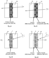
- the glazings illustrated on the Figures 1A to 1D are glazings with electrically controllable optical transmission properties between a transparent state and a white diffusing state.
- the glazing according to the invention has the particularity of being able to be used as a projection screen ( Figures 1C and 1D ), ie for a spectator on the projector side, rather than as a rear projection screen, ie in which the projector is located behind the glazing.
- the glazing comprises, between two sheets of glass 2A, 2B, more generally two sheets with glass function, an active system 4 switchable between a transparent state and a diffusing state, for example a white diffusing state, and a transparent stack and reflecting 6 on the back sheet 2A, ie on the sheet opposite the projector.
- a transparent state and a diffusing state for example a white diffusing state
- a transparent stack and reflecting 6 on the back sheet 2A ie on the sheet opposite the projector.
- the active system 4 is of any suitable type. An example will be given in more detail later for illustrative purposes.
- the invention relates more particularly to the transparent and reflective stack 6.
- the face 2 is thus the inner face (i.e. the face turned towards the inside of the glazing) of the first sheet with glass function 2A.
- the transparent and reflective stack 6 is multilayer, that is to say, formed of several thin layers deposited on the sheet glass function 2A.
- a layer A (or a stack of layers) formed (or deposited) on a layer B
- a layer A formed either directly on the layer B and therefore in contact with the layer B, is formed on layer B with the interposition of one or more layers between layer A and layer B.
- the transparent and reflective stack 6 is formed directly on the sheet glass function 2A.
- one or more intermediate layers may be interposed.
- the transparent and reflective stack 6 is formed on the sheet with a glass function.
- the transparent and reflective stack 6 essentially comprises a metallic functional coating 8, and a dielectric functional coating 10 of high optical index and of significant optical thickness (see FIG. figure 2 ).
- a metallic functional coating 8 a metallic functional coating 8 of high optical index and of significant optical thickness (see FIG. figure 2 ).
- dielectric functional coating 10 of high optical index and of significant optical thickness (see FIG. figure 2 ).
- functional is meant that these coatings are essential to obtain the reflective function with good color contrast sought by the invention.
- the number of functional coatings 8, 10 is of any suitable type, but the stack preferably has only one metallic functional coating 8 and preferably only one dielectric functional coating 10, as in the example illustrated in FIG. figure 2 .
- the metallic functional coating 8 is, in the example, formed of a single metal layer, more precisely, of a single layer of silver.
- the functional metal coating is based on silver or aluminum or metal alloy containing silver or aluminum, for example consisting entirely of silver or aluminum.
- thickness means a geometric thickness
- the dielectric functional coating is of high optical index and optical thickness sufficient for the glazing to have three reflection peaks at three visible wavelengths, as shown in FIG. figure 3 .
- the wavelengths of the visible range extend from 390 nm to 780 nm.
- the high optical index dielectric functional material has, for example, a refractive index ranging from 1.8 to 2.3, measured at 550 nm.
- the dielectric functional coating preferably comprises a single layer.
- the dielectric functional coating preferably has an optical thickness of 800nm to 1600nm, preferably 900nm to 1400nm, more preferably 1000nm to 1300nm.
- optical thickness means the product of the geometrical thickness (i.e. physical) with the refraction index of the material (refractive index considered as intended at 550 nm).
- the total thickness of the various layers of the transparent and reflective stack 6 including the thickness of the or each metallic functional layer are low enough to obtain a light transmission T L of at least 65% to through the transparent and reflective stack, preferably at least 68%, preferably at least 70%.
- the dielectric functional coating 10 is formed on the metallic functional coating 8.
- the dielectric functional coating 10 is formed on the metallic functional coating 8.
- the metallic functional coating may be formed on the dielectric functional coating.
- the transparent and reflective stack 6 further preferably comprises a blocking layer 12 immediately in contact with the or each metallic functional layer of the metallic functional coating 8, and directly formed on and / or under the or each metal functional layer as shown on the figure 2 .
- Blocking layer (s) 12 are for example based on titanium or niobium.
- an optical thickness of the dielectric functional coating ranging from 800nm to 1600nm, preferably from 900nm to 1400nm, more preferably from 1000nm to 1300nm is preferred.
- the transparent and reflective stack 6 preferably comprises at least one antireflection coating 14 adjacent the or each metallic functional layer of the metallic functional coating 8.
- the number of anti-glare coatings is also of any suitable type. Moreover, the number, nature and thickness of the thin layers constituting each antireflection coating is also of any suitable type.
- the antireflection coating comprises at least one thin layer.
- an antireflection coating consisting of a single thin layer, it is of high optical index, for example of optical index between 1.8 and 2.3, for example a titanium oxide layer.
- the antireflection coating 14 underlying the functional metal coating 8 comprises, in addition to the layer 16 of high optical index deposited on the substrate 2A, an antireflection layer 18 of intermediate optical index, crystallized oxide base, for example based on zinc oxide.
- This layer 18, in addition to its antireflection function, is called "wetting", because it also serves to promote the crystallization of metal functional layers deposited directly on it, especially in the case of silver layers.
- the transparent and reflective stack 6 also preferably comprises a protective layer 20, for example also based on zinc oxide, as in the example illustrated.
- This layer serves, for example, to protect the silver layer during subsequent magnetron sputtering in a reactive atmosphere, for example to deposit the dielectric functional coating.
- the sheet 2A is then laminated to the sheet 2B via the active system 4.
- the figure 3 illustrates the reflectivity curve of the glazing without the active system and therefore the transparent and reflective stack 6.
- the liquid crystal system 1 is of configuration: PET sheet (ie sheet with a glass function forming a carrier substrate / electrode / functional film / electrode / PET sheet (ie second sheet with a glass function), the functional film being currently used in glazing Priva-Lite from SAINT-GOBAIN GLASS.
- the functional film comprising the nematic liquid crystal liquid emulsion is of a thickness of about 10 to 30 ⁇ m (preferably 20 to 25 micrometers).
- the PET sheets are about 175 ⁇ m thick.
- the two electrodes consist of ITO (tin doped indium oxide) resistivity about 100 ohms per square.
- the ITO layer formed on the reflective stack is illustrated on the figure 2 .
- liquid crystals these may be of the "NCAP” type, especially those used in the "Priva-Lite” or “PDLC” glazings which have been mentioned above.
- NCAP NCAP
- their birefringence is between 0.1 and 0.2, it is variable especially according to the medium used, of the order of 0.1 if the polymer of the medium is of the polyurethane (PU) type and the order of 0.2 if it is polyvinyl alcohol (PVA) type.
- PU polyurethane
- PVA polyvinyl alcohol
- the medium is indeed preferably based on a polymer of the family of PU (latex) and / or PVA, generally prepared in aqueous phase in a proportion of polymers of 15 to 50% by weight relative to water .
- the active elements vis-à-vis the light scattering are advantageously in the form of droplets of average diameter between 0.5 and 3 microns, especially between 1 and 2.5 microns, dispersed in the medium.
- the size of the droplets depends on a number of parameters, including the ease of emulsification of the active elements in the medium in question.
- these droplets represent between 120 and 220% by weight of the medium, in particular between 150 and 200% by weight, apart from the generally aqueous solvent of said medium.
- liquid crystals are chosen in the form of droplets with a diameter of about 2.5 ⁇ m when the medium is based on polyurethane latex (birefringence of about 0.1) and with a diameter of about 1 ⁇ m when the medium is rather based on polyvinyl alcohol (birefringence of about 0.2).
- the power supply uses voltages between 0 and 110 V.
- any suitable electrically controllable optical transmission system may be used in combination with the transparent stack and reflective according to the invention.
- this is an electrically controllable system between the two glazed sheets each forming a self-supporting electrode, the functional system being electrically controllable by means of the electrodes between a transparent state and a white diffusing state.
- the invention also relates to the projection system using the above glazing, namely a projection system comprising a glazing unit with electrically controllable optical transmission properties and a projector provided for illuminating the glazing in projection, ie with spectators. on the side of the projector, the glazing being arranged so that the incident light from the projector arrives on the active system before arriving and reflected at least partly on the transparent and reflective stack.
Landscapes
- Physics & Mathematics (AREA)
- Chemical & Material Sciences (AREA)
- Nonlinear Science (AREA)
- Crystallography & Structural Chemistry (AREA)
- Mathematical Physics (AREA)
- General Physics & Mathematics (AREA)
- Optics & Photonics (AREA)
- Dispersion Chemistry (AREA)
- Laminated Bodies (AREA)
- Joining Of Glass To Other Materials (AREA)
Description
La présente invention concerne des systèmes électrocommandables à propriétés optiques variables, et plus précisément des systèmes du type vitrage dont on peut modifier la diffusion lumineuse sous l'effet d'une alimentation électrique appropriée, comme les systèmes à cristaux liquides et les valves optiques.The present invention relates to electrically controllable systems with variable optical properties, and more precisely to systems of the glazing type whose light distribution can be modified under the effect of a suitable power supply, such as liquid crystal systems and optical valves.
Accessoirement, l'invention s'applique de façon similaire aux systèmes qui présentent une diffusion lumineuse significative, mais seulement dans une gamme étroite d'angles d'incidence de vision, comme les systèmes holographiques. Elle s'applique également aux systèmes thermotropes, ainsi qu'aux systèmes à particules en suspension (connus sous l'abréviation anglaise S. P. D pour "suspended particles display").Incidentally, the invention applies similarly to systems that exhibit significant light scattering, but only in a narrow range of viewing angle of vision, such as holographic systems. It also applies to thermotropic systems, as well as to suspended particle systems (known by the abbreviation S. P. D for "suspended particles display").
Les systèmes à cristaux liquides utilisent un film fonctionnel à base d'un médium en polymère(s) dans lequel sont dispersées des gouttelettes de cristaux liquides, notamment nématiques à anisotropie diélectrique positive. Les cristaux liquides, quand le film est mis sous tension, s'orientent selon un axe privilégié, ce qui autorise la vision. Hors tension, en l'absence d'alignement des cristaux, le film devient diffusant et empêche la vision. Des exemples sont décrits dans les brevets
Les systèmes à valves optiques utilisent généralement un film fonctionnel sous forme d'une matrice de polymère éventuellement réticulée, dans laquelle sont dispersées des microgouttelettes contenant des particules aptes à se placer selon une direction privilégiée sous l'action d'un champ électrique ou magnétique.The optical valve systems generally use a functional film in the form of an optionally crosslinked polymer matrix, in which are dispersed microdroplets containing particles able to be placed in a preferred direction under the action of an electric or magnetic field.
En fonction notamment du potentiel appliqué et/ou de la nature et de la concentration de particules orientables, le film va présenter une transmission lumineuse variable, généralement associée à une diffusion lumineuse variable (sous tension, les particules interceptent beaucoup moins la lumière que hors tension). Un exemple en est décrit dans le brevet
Beaucoup d'applications ont été envisagées pour ces types de système, par exemple pour équiper des cloisons internes ou constituer des vitrages extérieurs de bâtiments, (notamment dans des bureaux), ou dans des moyens de locomotion terrestres (train, voiture), aériens (avion) ou maritimes.Many applications have been envisaged for these types of systems, for example to equip internal partitions or to constitute external glazing of buildings, (in particular in offices), or in means of locomotion terrestrial (train, car), air ( airplane) or maritime.
Comme évoqué dans le brevet
Cependant, si ces systèmes sont relativement satisfaisants en rétroprojection, ils ne fonctionnent pas correctement en projection, c'est-à-dire lorsque les spectateurs se trouvent du côté du projecteur. L'image n'est pas d'intensité ni de contraste suffisant.However, if these systems are relatively satisfactory in rear projection, they do not work properly in projection, that is to say, when the spectators are on the side of the projector. The image is not of sufficient intensity or contrast.
Un but de l'invention est de fournir un vitrage à propriétés optiques électrocommandables entre un état transparent et un état diffusant qui puisse servir d'écran de projection à l'état diffusant.An object of the invention is to provide a glazing with electrically controllable optical properties between a transparent state and a diffusing state that can serve as projection screen in the diffusing state.
A cet effet, l'invention a pour objet un vitrage à propriétés de transmission optique électrocommandables, ayant, dans au moins un état électrocommandable, une transmission lumineuse TL supérieure ou égale à 60%, le vitrage comprenant :
- deux feuilles à fonction verrière ; et
- entre les deux feuilles à fonction verrière, un système actif à propriétés de transmission optique électrocommandables,
- une couche fonctionnelle métallique ; et
- un revêtement en matériau diélectrique d'indice optique élevé et d'épaisseur optique suffisante pour que le vitrage présente trois pics de réflexion à trois longueurs d'ondes visibles.
- two leaves with glass function; and
- between the two sheets with a glass function, an active system with electrically controllable optical transmission properties,
- a functional metallic layer; and
- a coating of dielectric material of high optical index and optical thickness sufficient for the glazing to have three reflection peaks at three visible wavelengths.
Un avantage majeur d'un tel vitrage est de pouvoir être utilisé en projection avec une bonne qualité d'image, notamment un bon contraste et une neutralité de couleur sans nuire à la fonctionnalité « transparente » du vitrage à son état transparent.A major advantage of such a glazing is to be used in projection with good image quality, including good contrast and color neutrality without impairing the "transparent" functionality of the glazing in its transparent state.
Il convient en effet non seulement d'améliorer l'image de projection à l'état diffusant mais également de préserver l'aspect du vitrage dans son état transparent.It is indeed not only necessary to improve the projection image in the diffusing state but also to preserve the appearance of the glazing in its transparent state.
Suivant des modes particuliers de réalisation, le dispositif selon l'invention comporte en outre l'une ou plusieurs des caractéristiques techniques ci-dessous, prise(s) isolément ou suivant toutes les combinaisons techniquement possibles :
- l'empilement transparent et réfléchissant a un pic bleu en réflexion à λ compris entre 420nm et 480nm ;
- l'empilement transparent et réfléchissant a un pic vert à λ compris entre 500nm et 570nm ;
- l'empilement transparent et réfléchissant a un pic rouge en réflexion à λ compris entre 600nm et 700nm ;
- d'au moins un état du vitrage, la réflectivité vérifie -2 ≤ a* ≤ 2 et -2 ≤ b* ≤ 2 dans le système L*, a*, b* ;
- la couche fonctionnelle métallique est par exemple à base d'aluminium, de préférence à base d'argent ;
- le vitrage comprend, de part et d'autre de la couche fonctionnelle métallique, un revêtement antireflet, de préférence comprenant une couche diélectrique à base d'un oxyde métallique, de préférence à base d'un oxyde de zinc dopé aluminium ou d'un oxyde de titane ;
- ledit empilement transparent et réfléchissant comprend une seule couche fonctionnelle métallique ;
- ledit matériau diélectrique a une épaisseur optique allant de 800nm à 1600nm, de préférence de 900nm à 1400nm, de préférence encore de 1000nm à 1300nm ;
- ledit matériau diélectrique d'indice optique élevé est à base d'oxyde métallique, de préférence à base d'un oxyde mixte de zinc et d'étain ;
- ledit matériau diélectrique d'indice optique élevé comprend une seule couche ;
- ledit empilement transparent et réfléchissant est formé sur l'une des deux feuilles à fonction verrière ;
- ledit empilement transparent et réfléchissant est formé sur un substrat rapporté sur l'une des deux feuilles à fonction verrière, par exemple un film en matière thermoplastique ;
- le vitrage comprend un intercalaire de feuilletage en matière thermoplastique, dans lequel les deux feuilles à fonction verrière sont feuilletées ensemble par l'intermédiaire de l'intercalaire de feuilletage ;
- le vitrage présente dans au moins un état électrocommandable, une transmission lumineuse TL supérieure ou égale à 70%.
- the transparent and reflective stack has a blue peak in reflection at λ between 420 nm and 480 nm;
- the transparent and reflective stack has a green peak at λ between 500 nm and 570 nm;
- the transparent and reflective stack has a red peak in reflection at λ between 600nm and 700nm;
- of at least one state of the glazing, the reflectivity satisfies -2 ≤ a * ≤ 2 and -2 ≤ b * ≤ 2 in the system L *, a *, b *;
- the metal functional layer is for example based on aluminum, preferably based on silver;
- the glazing comprises, on either side of the metallic functional layer, an antireflection coating, preferably comprising a dielectric layer based on a metal oxide, preferably based on an aluminum doped zinc oxide or on a metal oxide layer; titanium oxide;
- said transparent and reflective stack comprises a single metallic functional layer;
- said dielectric material has an optical thickness ranging from 800nm to 1600nm, preferably from 900nm to 1400nm, more preferably from 1000nm to 1300nm;
- said high optical index dielectric material is based on metal oxide, preferably based on a mixed oxide of zinc and tin;
- said high optical index dielectric material comprises a single layer;
- said transparent and reflective stack is formed on one of the two glass-effect sheets;
- said transparent and reflective stack is formed on a substrate attached to one of the two glass-effect sheets, for example a film of thermoplastic material;
- the glazing comprises a laminating interlayer made of thermoplastic material, in which the two glass-effect sheets are laminated together by means of the lamination interlayer;
- the glazing has at least one electrically controllable state, a light transmission T L greater than or equal to 70%.
L'invention a également pour objet un système de projection comprenant un vitrage tel que défini ci-dessus et un projecteur.The invention also relates to a projection system comprising a glazing unit as defined above and a projector.
L'invention a encore pour objet un procédé de projection utilisant un projecteur et un vitrage tel que défini ci-dessus, le projecteur étant utilisant en projection (i.e. observateur du côté du projecteur).The invention also relates to a projection method using a projector and a glazing as defined above, the projector being used in projection (i.e. observer on the side of the projector).
L'invention sera mieux comprise à la lecture de la description qui va suivre, donnée uniquement à titre d'exemple, et faite en référence aux dessins annexés, sur lesquels :
- les
figures 1A à 1D sont des vues schématiques en coupe de systèmes de projection comprenant chacun un projecteur et un vitrage électrocommandable selon l'art antérieur sur lesfigure 1A et 1B et selon l'invention sur lesfigures 1C et 1D ; - la
figure 2 est une vue schématique en coupe d'un empilement transparent et réfléchissant prévu sur l'une des feuilles à fonction verrière du vitrage selon l'invention ; et - la
figure 3 est un diagramme illustrant la réflectivité de l'empilement transparent et réfléchissant en fonction de la longueur d'onde et mettant en évidence trois pics de réflexion dans le domaine visible.
- the
Figures 1A to 1D are schematic sectional views of projection systems each comprising a projector and an electrically controllable glazing according to the prior art on theFigure 1A and 1B and according to the inventionFigures 1C and 1D ; - the
figure 2 is a schematic sectional view of a transparent and reflective stack provided on one of the glass-function sheets of the glazing according to the invention; and - the
figure 3 is a diagram illustrating the reflectivity of the transparent and reflective stack as a function of the wavelength and highlighting three reflection peaks in the visible range.
Les dessins ne sont pas à l'échelle, pour une représentation claire, car les différences d'épaisseur entre les feuilles à fonction verrière et les autres couches sont importantes, par exemple de l'ordre d'un facteur 500.The drawings are not to scale, for a clear representation, because the differences in thickness between the sheets with a glass function and the other layers are important, for example of the order of a factor of 500.
Les vitrages illustrés sur les
Comme expliqué ci-dessus, le vitrage selon l'invention présente la particularité de pouvoir être utilisé comme écran de projection (
A cet effet, le vitrage comprend, entre deux feuilles de verre 2A, 2B, plus généralement deux feuilles à fonction verrière, un système actif 4 commutable entre un état transparent et un état diffusant, par exemple un état diffusant blanc, et un empilement transparent et réfléchissant 6 sur la feuille arrière 2A, i.e. sur la feuille opposée au projecteur.For this purpose, the glazing comprises, between two sheets of
Le système actif 4 est de tout type adapté. Un exemple sera donné plus en détail plus après à titre illustratif.The
L'invention concerne plus particulièrement l'empilement transparent et réfléchissant 6.The invention relates more particularly to the transparent and
Il s'agit d'un empilement de couches minces déposé sur la face 2 du vitrage, en numérotant les faces du vitrage à partir du côté opposé au projecteur 7 illustré sur les
La face 2 est ainsi la face interne (i.e. la face tournée vers l'intérieur du vitrage) de la première feuille à fonction verrière 2A.The face 2 is thus the inner face (i.e. the face turned towards the inside of the glazing) of the first sheet with
L'empilement transparent et réfléchissant 6 est multicouches, c'est-à-dire formé de plusieurs couches minces déposées sur la feuille à fonction verrière 2A.The transparent and
On entend, dans tout le texte, par « une couche A (ou un empilement de couches) formée (ou déposée) sur une couche B », une couche A formée soit directement sur la couche B et donc en contact avec la couche B, soit formée sur la couche B avec interposition d'une ou plusieurs couches entre la couche A et la couche B.Throughout the text is meant "a layer A (or a stack of layers) formed (or deposited) on a layer B", a layer A formed either directly on the layer B and therefore in contact with the layer B, is formed on layer B with the interposition of one or more layers between layer A and layer B.
L'empilement transparent et réfléchissant 6 est formé directement sur la feuille à fonction verrière 2A.The transparent and
En variante cependant, une ou plusieurs couches intermédiaires peuvent être interposées.Alternatively, however, one or more intermediate layers may be interposed.
D'une manière générale, l'empilement transparent et réfléchissant 6 est formé sur la feuille à fonction verrière.In a general manner, the transparent and
L'empilement transparent et réfléchissant 6 comprend essentiellement un revêtement fonctionnel métallique 8, et un revêtement fonctionnel diélectrique 10 d'indice optique élevé et d'épaisseur optique importante (voir
Le nombre de revêtements fonctionnels 8, 10 est de tout type adapté, mais l'empilement ne présente de préférence qu'un seul revêtement fonctionnel métallique 8 et de préférence qu'un seul revêtement fonctionnel diélectrique 10, comme dans l'exemple illustré sur la
Le revêtement fonctionnel métallique 8 est, dans l'exemple, formé d'une seule couche métallique, plus précisément, d'une seule couche d'argent.The metallic
De façon avantageuse, le revêtement fonctionnel métallique est à base d'argent ou d'aluminium ou à base d'alliage métallique contenant de l'argent ou de l'aluminium, par exemple constitué entièrement d'argent ou d'aluminium.Advantageously, the functional metal coating is based on silver or aluminum or metal alloy containing silver or aluminum, for example consisting entirely of silver or aluminum.
Dans le cas d'une seule couche d'argent, elle aura par exemple une épaisseur entre 3 et 10 nm.In the case of a single layer of silver, it will have for example a thickness between 3 and 10 nm.
A noter que, sauf indication contraire, on entend par épaisseur une épaisseur géométrique.Note that, unless otherwise indicated, thickness means a geometric thickness.
Le revêtement fonctionnel diélectrique est d'indice optique élevé et d'épaisseur optique suffisante pour que le vitrage présente trois pics de réflexion à trois longueurs d'ondes visibles, comme représenté sur la
Les longueurs d'onde du domaine visible s'étendent de 390nm à 780nm.The wavelengths of the visible range extend from 390 nm to 780 nm.
Le matériau fonctionnel diélectrique d'indice optique élevé a par exemple un indice de réfraction allant de 1,8 à 2,3 mesuré à 550nm.The high optical index dielectric functional material has, for example, a refractive index ranging from 1.8 to 2.3, measured at 550 nm.
Il s'agit par exemple d'un matériau à base d'oxyde métallique, de préférence à base d'un oxyde mixte de zinc et d'étain ou à base d'oxyde de titane.This is for example a metal oxide material, preferably based on a mixed oxide of zinc and tin or titanium oxide.
Comme indiqué préalablement ci-dessus, le revêtement fonctionnel diélectrique comprend de préférence une seule couche.As indicated above, the dielectric functional coating preferably comprises a single layer.
Le revêtement fonctionnel diélectrique a de préférence une épaisseur optique allant de 800nm à 1600nm, de préférence de 900nm à 1400nm, de préférence encore de 1000nm à 1300nm.The dielectric functional coating preferably has an optical thickness of 800nm to 1600nm, preferably 900nm to 1400nm, more preferably 1000nm to 1300nm.
On entend par « épaisseur optique » le produit de l'épaisseur géométrique (i.e. physique) avec l'indice de réfraction du matériau (indice de réfraction considéré comme le veut l'usage à 550nm).The term "optical thickness" means the product of the geometrical thickness (i.e. physical) with the refraction index of the material (refractive index considered as intended at 550 nm).
D'une manière générale, l'épaisseur totale des différentes couches de l'empilement transparent et réfléchissant 6 et notamment l'épaisseur de la ou chaque couche métallique fonctionnelle, sont suffisamment faibles pour obtenir une transmission lumineuse TL de 65% au moins à travers l'empilement transparent et réfléchissant, de préférence au moins 68%, de préférence au moins 70%.Generally, the total thickness of the various layers of the transparent and
En outre, grâce à cette configuration, on obtient une neutralité en couleur de l'empilement transparent et réfléchissant. Les valeurs de a* et b* dans le système L, a*, b* sont ainsi comprises entre -2 et 2, même entre -1 et 1 pour a*.In addition, thanks to this configuration, we obtain a color neutrality of the transparent and reflective stack. The values of a * and b * in the system L, a *, b * are thus between -2 and 2, even between -1 and 1 for a *.
Dans l'exemple illustré, on a plus particulièrement a*=0,7 et b*=-1.8, ce qui correspond à une couleur en réflexion relativement neutre, proche du blanc.In the example illustrated, we have more particularly a * = 0.7 and b * = - 1.8, which corresponds to a relatively neutral reflection color, close to white.
A noter que, dans l'exemple illustré sur la
D'une manière générale, le revêtement fonctionnel diélectrique 10 est formé sur le revêtement fonctionnel métallique 8. Mais en variante, le revêtement fonctionnel métallique peut être formé sur le revêtement fonctionnel diélectrique.In general, the dielectric
De préférence, l'empilement transparent et réfléchissant 6 comprend en outre de préférence une couche de blocage 12 immédiatement en contact avec la ou chaque couche fonctionnelle métallique du revêtement fonctionnel métallique 8, et directement formée sur et/ou sous la ou chaque couche fonctionnelle métallique, comme illustré sur la
Ainsi d'une manière générale, il s'agit d'un vitrage à propriétés de transmission optique électrocommandables, ayant, dans au moins un état électrocommandable, une transmission lumineuse TL supérieure ou égale à 60%, le vitrage comprenant :
- deux feuilles à fonction verrière ; et
- entre les deux feuilles à fonction verrière, un système actif à propriétés de transmission optique électrocommandables,
- une couche fonctionnelle métallique ;
- un revêtement en matériau diélectrique d'indice optique élevé et d'épaisseur optique suffisante pour que le vitrage présente trois pics de réflexion à trois longueurs d'ondes visibles.
- two leaves with glass function; and
- between the two sheets with a glass function, an active system with electrically controllable optical transmission properties,
- a functional metallic layer;
- a coating of dielectric material of high optical index and optical thickness sufficient for the glazing to have three reflection peaks at three visible wavelengths.
L'épaisseur optique du revêtement fonctionnel diélectrique est choisie de telle sorte que :
- l'empilement transparent et réfléchissant a un pic bleu en réflexion à λ compris entre 420nm et 480nm ;
- l'empilement transparent et réfléchissant a un pic vert à λ compris entre 500nm et 570nm ;
- l'empilement transparent et réfléchissant a un pic rouge en réflexion à λ compris entre 600nm et 700nm ;
- d'au moins un état du vitrage, la réflectivité vérifie -2 ≤ a* ≤ 2 et -2 ≤ b* ≤ 2 dans le système L*, a*, b*.
- the transparent and reflective stack has a blue peak in reflection at λ between 420 nm and 480 nm;
- the transparent and reflective stack has a green peak at λ between 500 nm and 570 nm;
- the transparent and reflective stack has a red peak in reflection at λ between 600nm and 700nm;
- of at least one state of the glazing, the reflectivity satisfies -2 ≤ a * ≤ 2 and -2 ≤ b * ≤ 2 in the system L *, a *, b *.
Dans le cas d'une couche d'oxyde de titane, choisie dans l'exemple illustré sur la
Par ailleurs, l'empilement transparent et réfléchissant 6 comprend de préférence au moins un revêtement antireflet 14 jouxtant la ou chaque couche fonctionnelle métallique du revêtement fonctionnel métallique 8.Furthermore, the transparent and
Le nombre de revêtements antireflets est également de tout type adapté. Qui plus est, le nombre, la nature et l'épaisseur des couches minces constituant chaque revêtement antireflet est également de tout type adapté.The number of anti-glare coatings is also of any suitable type. Moreover, the number, nature and thickness of the thin layers constituting each antireflection coating is also of any suitable type.
Le revêtement antireflet comprend au moins une couche mince. Dans le cas d'un revêtement antireflet constitué d'une seule couche mince, elle est d'indice optique élevé, par exemple d'indice optique compris entre 1,8 et 2,3, par exemple une couche d'oxyde de titane.The antireflection coating comprises at least one thin layer. In the case of an antireflection coating consisting of a single thin layer, it is of high optical index, for example of optical index between 1.8 and 2.3, for example a titanium oxide layer.
Dans le cas d'un revêtement antireflet constitué de plusieurs couches minces, il y a alternance couche d'indice optique élevé / couche d'indice optique intermédiaire.In the case of an anti-reflective coating consisting of several layers thin, there is alternating high optical index layer / intermediate optical index layer.
Dans l'exemple illustré et de façon avantageuse, le revêtement antireflet 14 sous-jacent au revêtement fonctionnel métallique 8 comprend, outre la couche 16 d'indice optique élevé déposée sur le substrat 2A, une couche antireflet 18 d'indice optique intermédiaire, à base d'oxyde cristallisé, par exemple à base d'oxyde de zinc. Il s'agit de la dernière couche de l'empilement antireflet 14, i.e. de la couche supérieure. Cette couche 18, outre sa fonction antireflet, est dite de « mouillage », car elle a aussi pour fonction de favoriser la cristallisation des couches fonctionnelles métalliques déposées directement dessus, notamment dans le cas de couches à l'argent.In the illustrated example and advantageously, the
L'empilement transparent et réfléchissant 6 comprend également de préférence une couche de protection 20, par exemple également à base d'oxyde de zinc, comme dans l'exemple illustré. Cette couche a par exemple pour fonction de protéger la couche d'argent lors d'une pulvérisation magnétron subséquence en atmosphère réactive, par exemple pour déposer le revêtement fonctionnel diélectrique.The transparent and
Dans l'exemple illustré, il s'agit plus précisément, en partant du substrat 2A, d' une alternance de deux couches minces antireflets 16 et 18, surmontés d'un revêtement fonctionnel métallique 8, puis d'une couche bloqueuse 12 et d'une couche de protection 20.In the example illustrated, it is more precisely, starting from the
A titre d'exemple, l'empilement suivant a été déposé une feuille de verre standard de type silico sodo calcique servant de feuille 2A :
- TiO2(4,9nm)/ZnO(5,0nm)/Ag(7,0nm)/Ti(0,2nm)/ZnO(5,0nm)/TiO2(491,9nm)
- TiO 2 (4.9nm) / ZnO (5.0nm) / Ag (7.0nm) / Ti (0.2nm) / ZnO (5.0nm) / TiO 2 (491.9nm)
La feuille 2A est ensuite feuilletée à la feuille 2B par l'intermédiaire du système actif 4.The
La
Un système actif est décrit ci-dessous à titre d'exemple non limitatif.An active system is described below by way of non-limiting example.
Dans l'exemple qui suit, le système à cristaux liquides 1 est de configuration : feuille de PET (i.e feuille à fonction verrière formant susbtrat porteur/ électrode/film fonctionnel/électrode/feuille de PET (i.e. deuxième feuille à fonction verrière), le film fonctionnel étant actuellement utilisé dans les vitrages Priva-Lite de SAINT-GOBAIN GLASS.In the following example, the liquid crystal system 1 is of configuration: PET sheet (ie sheet with a glass function forming a carrier substrate / electrode / functional film / electrode / PET sheet (ie second sheet with a glass function), the functional film being currently used in glazing Priva-Lite from SAINT-GOBAIN GLASS.
Le film fonctionnel comportant l'émulsion liquide de cristaux liquides nématiques est d'une épaisseur d'environ 10 à 30 µm (de préférence 20 à 25 micromètres). Les feuilles de PET ont une épaisseur d'environ 175 µm. Les deux électrodes sont constituées d'ITO (oxyde d'indium dopé à l'étain) de résistivité environ 100 ohms par carré. La couche d'ITO formée sur l'empilement réfléchissant est illustrée sur la
On donne ci-après quelques détails sur les cristaux liquides et leur médium utilisables. En ce qui concerne les cristaux liquides, ceux-ci peuvent être du type " NCAP ", notamment ceux utilisés dans les vitrages " Priva-Lite " ou " PDLC " qui ont été mentionnés plus haut. En règle générale, leur biréfringence est comprise entre 0,1 et 0,2, elle est variable notamment en fonction du médium utilisé, de l'ordre de 0,1 si le polymère du médium est de type polyuréthane (PU) et de l'ordre de 0,2 s'il est de type alcool polyvinylique (PVA).Some details on the liquid crystals and their usable medium are given below. As regards the liquid crystals, these may be of the "NCAP" type, especially those used in the "Priva-Lite" or "PDLC" glazings which have been mentioned above. As a rule, their birefringence is between 0.1 and 0.2, it is variable especially according to the medium used, of the order of 0.1 if the polymer of the medium is of the polyurethane (PU) type and the order of 0.2 if it is polyvinyl alcohol (PVA) type.
Le médium est en effet de préférence à base d'un polymère de la famille des PU (latex) et/ou des PVA, généralement préparé en phase aqueuse dans une proportion de polymères de 15 à 50% en poids par rapport à l'eau.The medium is indeed preferably based on a polymer of the family of PU (latex) and / or PVA, generally prepared in aqueous phase in a proportion of polymers of 15 to 50% by weight relative to water .
Les éléments actifs vis-à-vis de la diffusion lumineuse sont avantageusement sous forme de gouttelettes de diamètre moyen compris entre 0,5 et 3 µm, notamment entre 1 et 2,5 µm, dispersées dans le médium. La taille des gouttelettes dépend d'un certain nombre de paramètres, dont notamment la facilité d'émulsion des éléments actifs dans le médium considéré. De préférence, ces gouttelettes représentent entre 120 et 220% en poids du médium, notamment entre 150 et 200% en poids, hormis le solvant, généralement aqueux dudit médium.The active elements vis-à-vis the light scattering are advantageously in the form of droplets of average diameter between 0.5 and 3 microns, especially between 1 and 2.5 microns, dispersed in the medium. The size of the droplets depends on a number of parameters, including the ease of emulsification of the active elements in the medium in question. Preferably, these droplets represent between 120 and 220% by weight of the medium, in particular between 150 and 200% by weight, apart from the generally aqueous solvent of said medium.
De manière particulièrement préférée, on choisit des cristaux liquides sous forme de gouttelettes d'un diamètre d'environ 2,5 µm quand le médium est à base de latex de polyuréthane (biréfringence d'environ 0,1) et d'un diamètre d'environ 1 µm quand le médium est plutôt à base de polyvinylalcool (biréfringence d'environ 0,2).Particularly preferably, liquid crystals are chosen in the form of droplets with a diameter of about 2.5 μm when the medium is based on polyurethane latex (birefringence of about 0.1) and with a diameter of about 1 μm when the medium is rather based on polyvinyl alcohol (birefringence of about 0.2).
L'alimentation électrique utilise des tensions comprises entre 0 et 110 V.The power supply uses voltages between 0 and 110 V.
En variante, tout système à transmission optique électrocommandable adapté peut être utilisé en combinaison avec l'empilement transparent et réfléchissant selon l'invention.Alternatively, any suitable electrically controllable optical transmission system may be used in combination with the transparent stack and reflective according to the invention.
Il s'agit d'une manière générale, d'un système électrocommandable intercalaire entre les deux feuilles à fonction verrière formant chacune une électrode autosupportée, le système fonctionnel étant électrocommandable au moyen des électrodes entre un état transparent et un état diffusant blanc.In general, this is an electrically controllable system between the two glazed sheets each forming a self-supporting electrode, the functional system being electrically controllable by means of the electrodes between a transparent state and a white diffusing state.
A noter également que l'invention vise également le système de projection utilisant le vitrage ci-dessus, à savoir un système de projection comprenant un vitrage à propriétés de transmission optique électrocommandables et un projecteur prévu pour éclairer le vitrage en projection, i.e. avec des spectateurs du côté du projecteur, le vitrage étant agencé de telle sorte que la lumière incidente en provenance du projecteur arrive sur le système actif avant d'arriver et de se réfléchir au moins en partie sur l'empilement transparent et réfléchissant.It should also be noted that the invention also relates to the projection system using the above glazing, namely a projection system comprising a glazing unit with electrically controllable optical transmission properties and a projector provided for illuminating the glazing in projection, ie with spectators. on the side of the projector, the glazing being arranged so that the incident light from the projector arrives on the active system before arriving and reflected at least partly on the transparent and reflective stack.
Claims (15)
- A glazing unit with electrically controllable optical transmission properties, having, in at least one electrically controllable state, a light transmission TL higher than or equal to 60%, the glazing unit comprising:- two sheets (2A, 2B) providing a glazing function; and- between the two sheets providing a glazing function, an active system (4) with electrically controllable optical transmission properties,in which the glazing unit furthermore comprises a reflective and transparent thin-film stack (6) comprising:- a metal functional film (8); and- a coating made of a dielectric material (10) of high refractive index and of sufficient optical thickness for the glazing unit to present three reflection peaks at three visible wavelengths.
- The glazing unit as claimed in claim 1, in which the reflective and transparent stack (6) has a blue peak in reflection at λ comprised between 420 nm and 480 nm.
- The glazing unit as claimed in claim 1 or 2, in which the reflective and transparent stack (6) has a green peak at λ comprised between 500 nm and 570 nm.
- The glazing unit as claimed in any one of the preceding claims, in which the reflective and transparent stack (6) has a red peak in reflection at λ comprised between 600 nm and 700 nm.
- The glazing unit as claimed in any one of the preceding claims, in which, in at least one state of the glazing unit, the reflectivity respects -2 ≤ a* ≤ 2 and -2 ≤ b* ≤ 2 in the L*, a*, b* system.
- The glazing unit as claimed in any one of the preceding claims, in which the metal functional film (8) is based on aluminum or based on silver.
- The glazing unit as claimed in any one of the preceding claims, comprising, on and/or under the metal functional film (8), an antireflection coating (14), preferably comprising a dielectric film based on a metal oxide and preferably based on aluminum-doped zinc oxide or titanium oxide.
- The glazing unit as claimed in any one of the preceding claims, in which said reflective and transparent stack (6) comprises a single metal functional film (8).
- The glazing unit as claimed in any one of the preceding claims, in which said dielectric material (10) of high refractive index has an optical thickness ranging from 800 nm to 1600 nm, preferably from 900 nm to 1400 nm and more preferably from 1000 nm to 1300 nm.
- The glazing unit as claimed in any one of the preceding claims, in which said dielectric material (10) of high refractive index is based on a metal oxide and preferably based on a mixed zinc tin oxide.
- The glazing unit as claimed in any one of the preceding claims, in which said dielectric material (10) of high refractive index comprises a single film.
- The glazing unit as claimed in any one of the preceding claims, comprising a lamination interlayer made of a thermoplastic material, in which the two sheets providing a glazing function are laminated together by way of the lamination interlayer.
- The glazing unit as claimed in any one of the preceding claims, having, in at least one electrically controllable state, a light transmission TL higher than or equal to 70%.
- A projection system comprising a glazing unit as claimed in any one of the preceding claims and a projector.
- A projection method using a projection system as claimed in the preceding claim, the projector being used in front projection.
Priority Applications (1)
| Application Number | Priority Date | Filing Date | Title |
|---|---|---|---|
| PL14827493T PL3080659T3 (en) | 2013-12-12 | 2014-12-10 | Electrically controllable device having variable optical properties |
Applications Claiming Priority (2)
| Application Number | Priority Date | Filing Date | Title |
|---|---|---|---|
| FR1362494A FR3015059B1 (en) | 2013-12-12 | 2013-12-12 | ELECTROCOMMANDABLE DEVICE WITH VARIABLE OPTICAL PROPERTIES |
| PCT/FR2014/053261 WO2015086997A1 (en) | 2013-12-12 | 2014-12-10 | Electrically controllable device having variable optical properties |
Publications (2)
| Publication Number | Publication Date |
|---|---|
| EP3080659A1 EP3080659A1 (en) | 2016-10-19 |
| EP3080659B1 true EP3080659B1 (en) | 2017-11-22 |
Family
ID=50624683
Family Applications (1)
| Application Number | Title | Priority Date | Filing Date |
|---|---|---|---|
| EP14827493.9A Active EP3080659B1 (en) | 2013-12-12 | 2014-12-10 | Electrically controllable device having variable optical properties |
Country Status (4)
| Country | Link |
|---|---|
| EP (1) | EP3080659B1 (en) |
| FR (1) | FR3015059B1 (en) |
| PL (1) | PL3080659T3 (en) |
| WO (1) | WO2015086997A1 (en) |
Family Cites Families (9)
| Publication number | Priority date | Publication date | Assignee | Title |
|---|---|---|---|---|
| US4435047A (en) | 1981-09-16 | 1984-03-06 | Manchester R & D Partnership | Encapsulated liquid crystal and method |
| EP0238164B1 (en) | 1986-01-17 | 1993-11-03 | Raychem Corporation | Liquid crystal panel |
| US4950052A (en) | 1988-08-29 | 1990-08-21 | Taliq Corporation | Encapsulated liquid crystal apparatus with a polymer additive |
| US5156452A (en) | 1989-07-20 | 1992-10-20 | Paul Drzaic | Encapsulated liquid crystal apparatus having low off-axis haze and operable by a sine-wave power source |
| CA2125561C (en) | 1991-11-01 | 2003-01-28 | Joseph Aloysius Check, Iii | Light valve employing a film comprising an encapsulated liquid suspension, and method of making such film |
| FR2751097B1 (en) * | 1996-07-10 | 1998-09-11 | Saint Gobain Vitrage | ELEMENTS WITH VARIABLE OPTICAL / ENERGY PROPERTIES |
| FR2752570B1 (en) * | 1996-08-22 | 1998-10-02 | Saint Gobain Vitrage | GLAZING WITH VARIABLE OPTICAL AND / OR ENERGY PROPERTIES |
| FR2779839B1 (en) | 1998-06-10 | 2003-06-06 | Saint Gobain Vitrage | ELECTRICALLY CONTROLLED SYSTEM WITH VARIABLE OPTICAL PROPERTIES |
| FR2827397B1 (en) * | 2001-07-12 | 2003-09-19 | Saint Gobain | ELECTROCOMMANDABLE DEVICE WITH VARIABLE OPTICAL PROPERTIES OR HOLOGRAPHIC, THERMOTROPIC OR SUSPENDED PARTICLE SYSTEM |
-
2013
- 2013-12-12 FR FR1362494A patent/FR3015059B1/en not_active Expired - Fee Related
-
2014
- 2014-12-10 PL PL14827493T patent/PL3080659T3/en unknown
- 2014-12-10 WO PCT/FR2014/053261 patent/WO2015086997A1/en active Application Filing
- 2014-12-10 EP EP14827493.9A patent/EP3080659B1/en active Active
Also Published As
| Publication number | Publication date |
|---|---|
| PL3080659T3 (en) | 2018-02-28 |
| WO2015086997A1 (en) | 2015-06-18 |
| FR3015059B1 (en) | 2016-01-01 |
| FR3015059A1 (en) | 2015-06-19 |
| EP3080659A1 (en) | 2016-10-19 |
Similar Documents
| Publication | Publication Date | Title |
|---|---|---|
| FR2827397A1 (en) | Element with variable optical properties, for use e.g. in back-projection screens operating by transmission, comprises an electrically operated system with variable light diffusion, e.g. a liquid crystal system, and light-absorbing elements | |
| CA2740130C (en) | Multiple glazing unit including at least one anti-glare coating, and use of an anti-glare coating in a multiple glazing unit | |
| EP3063002B1 (en) | Element made from transparent layers | |
| EP2856256B1 (en) | Process of projection or re-projection on a glass comprising a transparent layered element presenting diffuse reflection properties | |
| EP2859407B1 (en) | Reflective projection screen comprising a variable light scattering system | |
| EP2915005B1 (en) | Glazing comprising a variable light diffusion system and a pair of absorbers | |
| FR3069660B1 (en) | ELECTROCOMMANDABLE DEVICE WITH VARIABLE DIFFUSION BY LIQUID CRYSTALS. | |
| EP1858697A1 (en) | Automotive glazing with selective diffusion | |
| CA3046177A1 (en) | Transparent layered element comprising a display region | |
| EP0823653A1 (en) | Element with variable optical/energetic properties | |
| FR3062339A1 (en) | TRANSPARENT LAYER ELEMENT WITH DIFFUSE DIRECTIONAL REFLECTION | |
| EP2915004A1 (en) | Variable light diffusion system comprising a pdlc layer | |
| WO2020065038A1 (en) | Electrically controllable device having variable diffusion by liquid crystals, and method for same | |
| EP2936248B1 (en) | Glazing comprising a variable light diffusion system used as a screen | |
| WO2021198596A1 (en) | Electrically controllable device having variable diffusion by liquid crystals, and method for same | |
| EP3080659B1 (en) | Electrically controllable device having variable optical properties | |
| FR3086771A1 (en) | ELECTRICALLY CONTROLLABLE DEVICE WITH VARIABLE DIFFUSION BY LIQUID CRYSTALS AND METHOD THEREOF. | |
| WO2023237839A1 (en) | Luminous laminated glass panel comprising a functional coating | |
| WO2022263784A1 (en) | Glazing comprising a functional coating and an absorbing element | |
| WO2024061780A1 (en) | Bilateral display device | |
| FR3127826A1 (en) | OPTICAL SYSTEM Liquid crystals |
Legal Events
| Date | Code | Title | Description |
|---|---|---|---|
| PUAI | Public reference made under article 153(3) epc to a published international application that has entered the european phase |
Free format text: ORIGINAL CODE: 0009012 |
|
| 17P | Request for examination filed |
Effective date: 20160712 |
|
| AK | Designated contracting states |
Kind code of ref document: A1 Designated state(s): AL AT BE BG CH CY CZ DE DK EE ES FI FR GB GR HR HU IE IS IT LI LT LU LV MC MK MT NL NO PL PT RO RS SE SI SK SM TR |
|
| AX | Request for extension of the european patent |
Extension state: BA ME |
|
| RIN1 | Information on inventor provided before grant (corrected) |
Inventor name: LEYDER, CHARLES Inventor name: LEBEDEV, DMITRY Inventor name: SCHIAVONI, MICHELE Inventor name: VERMESCH, FRANCOIS-JULIEN Inventor name: LECAMP, GUILLAUME |
|
| DAX | Request for extension of the european patent (deleted) | ||
| GRAP | Despatch of communication of intention to grant a patent |
Free format text: ORIGINAL CODE: EPIDOSNIGR1 |
|
| INTG | Intention to grant announced |
Effective date: 20170622 |
|
| GRAS | Grant fee paid |
Free format text: ORIGINAL CODE: EPIDOSNIGR3 |
|
| GRAA | (expected) grant |
Free format text: ORIGINAL CODE: 0009210 |
|
| AK | Designated contracting states |
Kind code of ref document: B1 Designated state(s): AL AT BE BG CH CY CZ DE DK EE ES FI FR GB GR HR HU IE IS IT LI LT LU LV MC MK MT NL NO PL PT RO RS SE SI SK SM TR |
|
| REG | Reference to a national code |
Ref country code: GB Ref legal event code: FG4D Free format text: NOT ENGLISH |
|
| REG | Reference to a national code |
Ref country code: CH Ref legal event code: EP |
|
| REG | Reference to a national code |
Ref country code: IE Ref legal event code: FG4D Free format text: LANGUAGE OF EP DOCUMENT: FRENCH |
|
| REG | Reference to a national code |
Ref country code: AT Ref legal event code: REF Ref document number: 948926 Country of ref document: AT Kind code of ref document: T Effective date: 20171215 |
|
| REG | Reference to a national code |
Ref country code: FR Ref legal event code: PLFP Year of fee payment: 4 |
|
| REG | Reference to a national code |
Ref country code: DE Ref legal event code: R096 Ref document number: 602014017738 Country of ref document: DE |
|
| REG | Reference to a national code |
Ref country code: NL Ref legal event code: MP Effective date: 20171122 |
|
| REG | Reference to a national code |
Ref country code: LT Ref legal event code: MG4D |
|
| REG | Reference to a national code |
Ref country code: AT Ref legal event code: MK05 Ref document number: 948926 Country of ref document: AT Kind code of ref document: T Effective date: 20171122 |
|
| PG25 | Lapsed in a contracting state [announced via postgrant information from national office to epo] |
Ref country code: NO Free format text: LAPSE BECAUSE OF FAILURE TO SUBMIT A TRANSLATION OF THE DESCRIPTION OR TO PAY THE FEE WITHIN THE PRESCRIBED TIME-LIMIT Effective date: 20180222 Ref country code: FI Free format text: LAPSE BECAUSE OF FAILURE TO SUBMIT A TRANSLATION OF THE DESCRIPTION OR TO PAY THE FEE WITHIN THE PRESCRIBED TIME-LIMIT Effective date: 20171122 Ref country code: LT Free format text: LAPSE BECAUSE OF FAILURE TO SUBMIT A TRANSLATION OF THE DESCRIPTION OR TO PAY THE FEE WITHIN THE PRESCRIBED TIME-LIMIT Effective date: 20171122 Ref country code: ES Free format text: LAPSE BECAUSE OF FAILURE TO SUBMIT A TRANSLATION OF THE DESCRIPTION OR TO PAY THE FEE WITHIN THE PRESCRIBED TIME-LIMIT Effective date: 20171122 Ref country code: NL Free format text: LAPSE BECAUSE OF FAILURE TO SUBMIT A TRANSLATION OF THE DESCRIPTION OR TO PAY THE FEE WITHIN THE PRESCRIBED TIME-LIMIT Effective date: 20171122 Ref country code: SE Free format text: LAPSE BECAUSE OF FAILURE TO SUBMIT A TRANSLATION OF THE DESCRIPTION OR TO PAY THE FEE WITHIN THE PRESCRIBED TIME-LIMIT Effective date: 20171122 |
|
| PG25 | Lapsed in a contracting state [announced via postgrant information from national office to epo] |
Ref country code: BG Free format text: LAPSE BECAUSE OF FAILURE TO SUBMIT A TRANSLATION OF THE DESCRIPTION OR TO PAY THE FEE WITHIN THE PRESCRIBED TIME-LIMIT Effective date: 20180222 Ref country code: GR Free format text: LAPSE BECAUSE OF FAILURE TO SUBMIT A TRANSLATION OF THE DESCRIPTION OR TO PAY THE FEE WITHIN THE PRESCRIBED TIME-LIMIT Effective date: 20180223 Ref country code: RS Free format text: LAPSE BECAUSE OF FAILURE TO SUBMIT A TRANSLATION OF THE DESCRIPTION OR TO PAY THE FEE WITHIN THE PRESCRIBED TIME-LIMIT Effective date: 20171122 Ref country code: LV Free format text: LAPSE BECAUSE OF FAILURE TO SUBMIT A TRANSLATION OF THE DESCRIPTION OR TO PAY THE FEE WITHIN THE PRESCRIBED TIME-LIMIT Effective date: 20171122 Ref country code: AT Free format text: LAPSE BECAUSE OF FAILURE TO SUBMIT A TRANSLATION OF THE DESCRIPTION OR TO PAY THE FEE WITHIN THE PRESCRIBED TIME-LIMIT Effective date: 20171122 Ref country code: HR Free format text: LAPSE BECAUSE OF FAILURE TO SUBMIT A TRANSLATION OF THE DESCRIPTION OR TO PAY THE FEE WITHIN THE PRESCRIBED TIME-LIMIT Effective date: 20171122 |
|
| PG25 | Lapsed in a contracting state [announced via postgrant information from national office to epo] |
Ref country code: CZ Free format text: LAPSE BECAUSE OF FAILURE TO SUBMIT A TRANSLATION OF THE DESCRIPTION OR TO PAY THE FEE WITHIN THE PRESCRIBED TIME-LIMIT Effective date: 20171122 Ref country code: SK Free format text: LAPSE BECAUSE OF FAILURE TO SUBMIT A TRANSLATION OF THE DESCRIPTION OR TO PAY THE FEE WITHIN THE PRESCRIBED TIME-LIMIT Effective date: 20171122 Ref country code: CY Free format text: LAPSE BECAUSE OF FAILURE TO SUBMIT A TRANSLATION OF THE DESCRIPTION OR TO PAY THE FEE WITHIN THE PRESCRIBED TIME-LIMIT Effective date: 20171122 Ref country code: EE Free format text: LAPSE BECAUSE OF FAILURE TO SUBMIT A TRANSLATION OF THE DESCRIPTION OR TO PAY THE FEE WITHIN THE PRESCRIBED TIME-LIMIT Effective date: 20171122 Ref country code: DK Free format text: LAPSE BECAUSE OF FAILURE TO SUBMIT A TRANSLATION OF THE DESCRIPTION OR TO PAY THE FEE WITHIN THE PRESCRIBED TIME-LIMIT Effective date: 20171122 |
|
| REG | Reference to a national code |
Ref country code: CH Ref legal event code: PL |
|
| REG | Reference to a national code |
Ref country code: DE Ref legal event code: R097 Ref document number: 602014017738 Country of ref document: DE |
|
| PG25 | Lapsed in a contracting state [announced via postgrant information from national office to epo] |
Ref country code: IT Free format text: LAPSE BECAUSE OF FAILURE TO SUBMIT A TRANSLATION OF THE DESCRIPTION OR TO PAY THE FEE WITHIN THE PRESCRIBED TIME-LIMIT Effective date: 20171122 Ref country code: SM Free format text: LAPSE BECAUSE OF FAILURE TO SUBMIT A TRANSLATION OF THE DESCRIPTION OR TO PAY THE FEE WITHIN THE PRESCRIBED TIME-LIMIT Effective date: 20171122 |
|
| REG | Reference to a national code |
Ref country code: IE Ref legal event code: MM4A |
|
| PG25 | Lapsed in a contracting state [announced via postgrant information from national office to epo] |
Ref country code: MT Free format text: LAPSE BECAUSE OF FAILURE TO SUBMIT A TRANSLATION OF THE DESCRIPTION OR TO PAY THE FEE WITHIN THE PRESCRIBED TIME-LIMIT Effective date: 20171122 Ref country code: LU Free format text: LAPSE BECAUSE OF NON-PAYMENT OF DUE FEES Effective date: 20171210 |
|
| PLBE | No opposition filed within time limit |
Free format text: ORIGINAL CODE: 0009261 |
|
| STAA | Information on the status of an ep patent application or granted ep patent |
Free format text: STATUS: NO OPPOSITION FILED WITHIN TIME LIMIT |
|
| REG | Reference to a national code |
Ref country code: BE Ref legal event code: MM Effective date: 20171231 |
|
| 26N | No opposition filed |
Effective date: 20180823 |
|
| PG25 | Lapsed in a contracting state [announced via postgrant information from national office to epo] |
Ref country code: IE Free format text: LAPSE BECAUSE OF NON-PAYMENT OF DUE FEES Effective date: 20171210 |
|
| PG25 | Lapsed in a contracting state [announced via postgrant information from national office to epo] |
Ref country code: LI Free format text: LAPSE BECAUSE OF NON-PAYMENT OF DUE FEES Effective date: 20171231 Ref country code: SI Free format text: LAPSE BECAUSE OF FAILURE TO SUBMIT A TRANSLATION OF THE DESCRIPTION OR TO PAY THE FEE WITHIN THE PRESCRIBED TIME-LIMIT Effective date: 20171122 Ref country code: BE Free format text: LAPSE BECAUSE OF NON-PAYMENT OF DUE FEES Effective date: 20171231 Ref country code: CH Free format text: LAPSE BECAUSE OF NON-PAYMENT OF DUE FEES Effective date: 20171231 |
|
| PG25 | Lapsed in a contracting state [announced via postgrant information from national office to epo] |
Ref country code: MC Free format text: LAPSE BECAUSE OF FAILURE TO SUBMIT A TRANSLATION OF THE DESCRIPTION OR TO PAY THE FEE WITHIN THE PRESCRIBED TIME-LIMIT Effective date: 20171122 Ref country code: HU Free format text: LAPSE BECAUSE OF FAILURE TO SUBMIT A TRANSLATION OF THE DESCRIPTION OR TO PAY THE FEE WITHIN THE PRESCRIBED TIME-LIMIT; INVALID AB INITIO Effective date: 20141210 |
|
| PG25 | Lapsed in a contracting state [announced via postgrant information from national office to epo] |
Ref country code: RO Free format text: LAPSE BECAUSE OF FAILURE TO SUBMIT A TRANSLATION OF THE DESCRIPTION OR TO PAY THE FEE WITHIN THE PRESCRIBED TIME-LIMIT Effective date: 20171122 |
|
| PG25 | Lapsed in a contracting state [announced via postgrant information from national office to epo] |
Ref country code: MK Free format text: LAPSE BECAUSE OF FAILURE TO SUBMIT A TRANSLATION OF THE DESCRIPTION OR TO PAY THE FEE WITHIN THE PRESCRIBED TIME-LIMIT Effective date: 20171122 |
|
| PG25 | Lapsed in a contracting state [announced via postgrant information from national office to epo] |
Ref country code: TR Free format text: LAPSE BECAUSE OF FAILURE TO SUBMIT A TRANSLATION OF THE DESCRIPTION OR TO PAY THE FEE WITHIN THE PRESCRIBED TIME-LIMIT Effective date: 20171122 |
|
| PG25 | Lapsed in a contracting state [announced via postgrant information from national office to epo] |
Ref country code: PT Free format text: LAPSE BECAUSE OF FAILURE TO SUBMIT A TRANSLATION OF THE DESCRIPTION OR TO PAY THE FEE WITHIN THE PRESCRIBED TIME-LIMIT Effective date: 20171122 |
|
| PG25 | Lapsed in a contracting state [announced via postgrant information from national office to epo] |
Ref country code: AL Free format text: LAPSE BECAUSE OF FAILURE TO SUBMIT A TRANSLATION OF THE DESCRIPTION OR TO PAY THE FEE WITHIN THE PRESCRIBED TIME-LIMIT Effective date: 20171122 Ref country code: IS Free format text: LAPSE BECAUSE OF FAILURE TO SUBMIT A TRANSLATION OF THE DESCRIPTION OR TO PAY THE FEE WITHIN THE PRESCRIBED TIME-LIMIT Effective date: 20180322 |
|
| PGFP | Annual fee paid to national office [announced via postgrant information from national office to epo] |
Ref country code: GB Payment date: 20231102 Year of fee payment: 10 |
|
| PGFP | Annual fee paid to national office [announced via postgrant information from national office to epo] |
Ref country code: FR Payment date: 20231211 Year of fee payment: 10 Ref country code: DE Payment date: 20231031 Year of fee payment: 10 |
|
| PGFP | Annual fee paid to national office [announced via postgrant information from national office to epo] |
Ref country code: PL Payment date: 20231114 Year of fee payment: 10 |