EP3080560B1 - Device for measuring density - Google Patents
Device for measuring density Download PDFInfo
- Publication number
- EP3080560B1 EP3080560B1 EP14793095.2A EP14793095A EP3080560B1 EP 3080560 B1 EP3080560 B1 EP 3080560B1 EP 14793095 A EP14793095 A EP 14793095A EP 3080560 B1 EP3080560 B1 EP 3080560B1
- Authority
- EP
- European Patent Office
- Prior art keywords
- measuring
- vibration
- frequency
- measuring tube
- signal
- Prior art date
- Legal status (The legal status is an assumption and is not a legal conclusion. Google has not performed a legal analysis and makes no representation as to the accuracy of the status listed.)
- Active
Links
- 230000005284 excitation Effects 0.000 claims description 90
- 230000010363 phase shift Effects 0.000 claims description 54
- 230000033001 locomotion Effects 0.000 claims description 33
- 230000004044 response Effects 0.000 claims description 24
- 230000000737 periodic effect Effects 0.000 claims description 11
- RTAQQCXQSZGOHL-UHFFFAOYSA-N Titanium Chemical compound [Ti] RTAQQCXQSZGOHL-UHFFFAOYSA-N 0.000 claims description 8
- 239000010936 titanium Substances 0.000 claims description 8
- 229910052719 titanium Inorganic materials 0.000 claims description 8
- 229910052710 silicon Inorganic materials 0.000 claims description 4
- 239000010703 silicon Substances 0.000 claims description 4
- 238000013461 design Methods 0.000 claims description 3
- 230000005502 phase rule Effects 0.000 claims 8
- 238000005259 measurement Methods 0.000 description 102
- 230000010355 oscillation Effects 0.000 description 64
- 230000000875 corresponding effect Effects 0.000 description 46
- 238000005452 bending Methods 0.000 description 27
- 230000001419 dependent effect Effects 0.000 description 19
- 238000013016 damping Methods 0.000 description 18
- 238000011156 evaluation Methods 0.000 description 16
- 238000000034 method Methods 0.000 description 15
- 230000008569 process Effects 0.000 description 14
- 230000008878 coupling Effects 0.000 description 12
- 238000010168 coupling process Methods 0.000 description 12
- 238000005859 coupling reaction Methods 0.000 description 12
- 238000001739 density measurement Methods 0.000 description 12
- 238000012545 processing Methods 0.000 description 9
- 238000004364 calculation method Methods 0.000 description 8
- 239000003990 capacitor Substances 0.000 description 8
- 238000010586 diagram Methods 0.000 description 8
- 230000005520 electrodynamics Effects 0.000 description 8
- 230000008859 change Effects 0.000 description 7
- PXHVJJICTQNCMI-UHFFFAOYSA-N Nickel Chemical compound [Ni] PXHVJJICTQNCMI-UHFFFAOYSA-N 0.000 description 6
- QCWXUUIWCKQGHC-UHFFFAOYSA-N Zirconium Chemical compound [Zr] QCWXUUIWCKQGHC-UHFFFAOYSA-N 0.000 description 6
- 229910045601 alloy Inorganic materials 0.000 description 6
- 239000000956 alloy Substances 0.000 description 6
- 238000005516 engineering process Methods 0.000 description 6
- 239000010935 stainless steel Substances 0.000 description 6
- 229910001220 stainless steel Inorganic materials 0.000 description 6
- 229910052726 zirconium Inorganic materials 0.000 description 6
- 230000006399 behavior Effects 0.000 description 5
- 238000004891 communication Methods 0.000 description 5
- 230000006870 function Effects 0.000 description 5
- 229910052715 tantalum Inorganic materials 0.000 description 5
- GUVRBAGPIYLISA-UHFFFAOYSA-N tantalum atom Chemical compound [Ta] GUVRBAGPIYLISA-UHFFFAOYSA-N 0.000 description 5
- 230000005540 biological transmission Effects 0.000 description 4
- 238000009529 body temperature measurement Methods 0.000 description 4
- 238000006243 chemical reaction Methods 0.000 description 4
- 230000001143 conditioned effect Effects 0.000 description 4
- 238000012937 correction Methods 0.000 description 4
- 238000009826 distribution Methods 0.000 description 4
- 239000007789 gas Substances 0.000 description 4
- 239000007788 liquid Substances 0.000 description 4
- 238000012423 maintenance Methods 0.000 description 4
- 230000001105 regulatory effect Effects 0.000 description 4
- 238000004422 calculation algorithm Methods 0.000 description 3
- 230000007423 decrease Effects 0.000 description 3
- 229910052751 metal Inorganic materials 0.000 description 3
- 239000002184 metal Substances 0.000 description 3
- 229910052759 nickel Inorganic materials 0.000 description 3
- 230000003534 oscillatory effect Effects 0.000 description 3
- 230000002829 reductive effect Effects 0.000 description 3
- PEDCQBHIVMGVHV-UHFFFAOYSA-N Glycerine Chemical compound OCC(O)CO PEDCQBHIVMGVHV-UHFFFAOYSA-N 0.000 description 2
- 229910000831 Steel Inorganic materials 0.000 description 2
- 229910001362 Ta alloys Inorganic materials 0.000 description 2
- 229910001069 Ti alloy Inorganic materials 0.000 description 2
- 229910001093 Zr alloy Inorganic materials 0.000 description 2
- 230000033228 biological regulation Effects 0.000 description 2
- 239000004020 conductor Substances 0.000 description 2
- 230000000694 effects Effects 0.000 description 2
- 230000005484 gravity Effects 0.000 description 2
- 230000003993 interaction Effects 0.000 description 2
- 239000000463 material Substances 0.000 description 2
- BASFCYQUMIYNBI-UHFFFAOYSA-N platinum Chemical compound [Pt] BASFCYQUMIYNBI-UHFFFAOYSA-N 0.000 description 2
- 239000000047 product Substances 0.000 description 2
- 230000001681 protective effect Effects 0.000 description 2
- 230000011664 signaling Effects 0.000 description 2
- 239000010959 steel Substances 0.000 description 2
- 230000004936 stimulating effect Effects 0.000 description 2
- XLYOFNOQVPJJNP-UHFFFAOYSA-N water Substances O XLYOFNOQVPJJNP-UHFFFAOYSA-N 0.000 description 2
- 229910000915 Free machining steel Inorganic materials 0.000 description 1
- 229910000746 Structural steel Inorganic materials 0.000 description 1
- 230000009471 action Effects 0.000 description 1
- 230000001276 controlling effect Effects 0.000 description 1
- 230000002596 correlated effect Effects 0.000 description 1
- 230000001934 delay Effects 0.000 description 1
- 238000011161 development Methods 0.000 description 1
- 230000018109 developmental process Effects 0.000 description 1
- 238000007599 discharging Methods 0.000 description 1
- 230000005489 elastic deformation Effects 0.000 description 1
- 238000004146 energy storage Methods 0.000 description 1
- 238000007572 expansion measurement Methods 0.000 description 1
- 230000009969 flowable effect Effects 0.000 description 1
- 239000012530 fluid Substances 0.000 description 1
- 239000011521 glass Substances 0.000 description 1
- 235000011187 glycerol Nutrition 0.000 description 1
- 230000006872 improvement Effects 0.000 description 1
- 238000011835 investigation Methods 0.000 description 1
- 230000002427 irreversible effect Effects 0.000 description 1
- 230000002045 lasting effect Effects 0.000 description 1
- 230000007257 malfunction Effects 0.000 description 1
- 238000004519 manufacturing process Methods 0.000 description 1
- 238000010327 methods by industry Methods 0.000 description 1
- 238000012544 monitoring process Methods 0.000 description 1
- 239000002245 particle Substances 0.000 description 1
- 229910052697 platinum Inorganic materials 0.000 description 1
- 238000004382 potting Methods 0.000 description 1
- 238000004886 process control Methods 0.000 description 1
- 238000011084 recovery Methods 0.000 description 1
- 230000009467 reduction Effects 0.000 description 1
- 230000002441 reversible effect Effects 0.000 description 1
- 239000011265 semifinished product Substances 0.000 description 1
- 230000035945 sensitivity Effects 0.000 description 1
- 230000008054 signal transmission Effects 0.000 description 1
- 238000004088 simulation Methods 0.000 description 1
- 239000007787 solid Substances 0.000 description 1
- 230000003068 static effect Effects 0.000 description 1
- 230000002123 temporal effect Effects 0.000 description 1
- 238000012360 testing method Methods 0.000 description 1
- 238000012546 transfer Methods 0.000 description 1
Images


Classifications
-
- G—PHYSICS
- G01—MEASURING; TESTING
- G01F—MEASURING VOLUME, VOLUME FLOW, MASS FLOW OR LIQUID LEVEL; METERING BY VOLUME
- G01F1/00—Measuring the volume flow or mass flow of fluid or fluent solid material wherein the fluid passes through a meter in a continuous flow
- G01F1/76—Devices for measuring mass flow of a fluid or a fluent solid material
- G01F1/78—Direct mass flowmeters
- G01F1/80—Direct mass flowmeters operating by measuring pressure, force, momentum, or frequency of a fluid flow to which a rotational movement has been imparted
- G01F1/84—Coriolis or gyroscopic mass flowmeters
- G01F1/845—Coriolis or gyroscopic mass flowmeters arrangements of measuring means, e.g., of measuring conduits
- G01F1/8468—Coriolis or gyroscopic mass flowmeters arrangements of measuring means, e.g., of measuring conduits vibrating measuring conduits
- G01F1/8472—Coriolis or gyroscopic mass flowmeters arrangements of measuring means, e.g., of measuring conduits vibrating measuring conduits having curved measuring conduits, i.e. whereby the measuring conduits' curved center line lies within a plane
-
- G—PHYSICS
- G01—MEASURING; TESTING
- G01N—INVESTIGATING OR ANALYSING MATERIALS BY DETERMINING THEIR CHEMICAL OR PHYSICAL PROPERTIES
- G01N9/00—Investigating density or specific gravity of materials; Analysing materials by determining density or specific gravity
- G01N9/002—Investigating density or specific gravity of materials; Analysing materials by determining density or specific gravity using variation of the resonant frequency of an element vibrating in contact with the material submitted to analysis
-
- G—PHYSICS
- G01—MEASURING; TESTING
- G01F—MEASURING VOLUME, VOLUME FLOW, MASS FLOW OR LIQUID LEVEL; METERING BY VOLUME
- G01F1/00—Measuring the volume flow or mass flow of fluid or fluent solid material wherein the fluid passes through a meter in a continuous flow
- G01F1/76—Devices for measuring mass flow of a fluid or a fluent solid material
- G01F1/78—Direct mass flowmeters
- G01F1/80—Direct mass flowmeters operating by measuring pressure, force, momentum, or frequency of a fluid flow to which a rotational movement has been imparted
- G01F1/84—Coriolis or gyroscopic mass flowmeters
- G01F1/845—Coriolis or gyroscopic mass flowmeters arrangements of measuring means, e.g., of measuring conduits
- G01F1/8468—Coriolis or gyroscopic mass flowmeters arrangements of measuring means, e.g., of measuring conduits vibrating measuring conduits
-
- G—PHYSICS
- G01—MEASURING; TESTING
- G01N—INVESTIGATING OR ANALYSING MATERIALS BY DETERMINING THEIR CHEMICAL OR PHYSICAL PROPERTIES
- G01N11/00—Investigating flow properties of materials, e.g. viscosity, plasticity; Analysing materials by determining flow properties
- G01N11/02—Investigating flow properties of materials, e.g. viscosity, plasticity; Analysing materials by determining flow properties by measuring flow of the material
-
- G—PHYSICS
- G01—MEASURING; TESTING
- G01N—INVESTIGATING OR ANALYSING MATERIALS BY DETERMINING THEIR CHEMICAL OR PHYSICAL PROPERTIES
- G01N11/00—Investigating flow properties of materials, e.g. viscosity, plasticity; Analysing materials by determining flow properties
- G01N11/10—Investigating flow properties of materials, e.g. viscosity, plasticity; Analysing materials by determining flow properties by moving a body within the material
- G01N11/16—Investigating flow properties of materials, e.g. viscosity, plasticity; Analysing materials by determining flow properties by moving a body within the material by measuring damping effect upon oscillatory body
-
- G—PHYSICS
- G01—MEASURING; TESTING
- G01N—INVESTIGATING OR ANALYSING MATERIALS BY DETERMINING THEIR CHEMICAL OR PHYSICAL PROPERTIES
- G01N9/00—Investigating density or specific gravity of materials; Analysing materials by determining density or specific gravity
- G01N9/002—Investigating density or specific gravity of materials; Analysing materials by determining density or specific gravity using variation of the resonant frequency of an element vibrating in contact with the material submitted to analysis
- G01N2009/006—Investigating density or specific gravity of materials; Analysing materials by determining density or specific gravity using variation of the resonant frequency of an element vibrating in contact with the material submitted to analysis vibrating tube, tuning fork
Definitions
- the invention relates to a vibronic density measuring device for measuring a density, p, of a flowable medium, in particular a fluid flowing in a pipeline.
- Such density measuring devices for example designed as so-called four-wire or so-called two-wire devices - have been known for a long time, not least in the form of Coriolis mass flow / density measuring devices or also in the form of viscosity-density measuring devices, and are established in industrial use .
- Examples of such vibronic density measuring devices or measuring transducers suitable for them are, inter alia, in US-A 2004/0123645 , the US-A 2006/0096390 , the US-A 2007/0119264 , the US-A 2008/0047362 , the US-A 2008/0190195 , the US-A 2010/0005887 , the US-A 2010/0011882 , the US-A 2010/0257943 , the US-A 2011/0161017 , the US-A 2011/0219872 , the US-A 2011/0265580 , the US-A 2012/0123705 , the US-A 44 91 009 , the US-A 45 24 610 , the US-A 48 01 897 , the US-A 49 96 871 , the US-A 50 24 104 , the US-A 52 87 754 , the US-A 52 91 792 , the US-A 53 49 872 , the US-A 55 31 126
- the transducer of each of the density measuring devices shown therein comprises at least one at least partially straight and / or at least partially curved, for example U-, V-, S-, Z- or ⁇ -shaped, measuring tube with a lumen surrounded by a pipe wall for guiding the medium, said pipe wall - depending on the use - typically made of a metal, such as titanium or a titanium alloy, tantalum or a tantalum alloy, zirconium or a zirconium alloy, a stainless steel or a nickel-based alloy, or for example also consist of silicon and a caliber of the same measuring tube - depending on the use - can typically be in a range between 0.5 mm and 100 mm.
- a metal such as titanium or a titanium alloy, tantalum or a tantalum alloy, zirconium or a zirconium alloy, a stainless steel or a nickel-based alloy, or for example also consist of silicon and a caliber of the same measuring tube - depending on the use - can typically be
- the at least one measuring tube of such a transducer is set up to guide medium in the lumen and to be allowed to vibrate in the meantime in such a way that there are useful vibrations, namely mechanical vibrations around a position of rest with a also determined by the density of the medium, i.e. as a measure of the density usable usable frequency.
- useful vibrations namely mechanical vibrations around a position of rest with a also determined by the density of the medium, i.e. as a measure of the density usable usable frequency.
- bending vibrations at a natural resonance frequency are typically used as useful vibrations, for example those bending vibrations that correspond to a fundamental natural bending vibration mode inherent in the transducer, in which the vibrations of the measuring tube are those resonance vibrations that have exactly one antinode.
- the useful vibrations are typically designed in such a way that the same measuring tube oscillates around an imaginary axis of vibration that imaginatively connects an inlet-side and an outlet-side end of the measuring tube in the manner of a cantilever clamped at one end, whereas in the case of transducers with a straight measuring tube the useful vibrations are mostly bending vibrations in a single imaginary vibration plane.
- transducers with two measuring tubes these are mostly integrated into the respective process line via an inlet-side distributor piece extending between the measuring tubes and an inlet-side connection flange and via an outlet-side distributor piece extending between the measuring tubes and an outlet-side connection flange.
- the latter usually communicates with the process line via a connecting tube opening on the inlet side and a connecting tube opening on the outlet side.
- transducers with a single measuring tube each comprise at least one one-piece or multi-part, For example, tubular, box-shaped or plate-shaped counter-oscillator, which is coupled to the measuring tube on the inlet side to form a first coupling zone and which is coupled to the measuring tube on the outlet side to form a second coupling zone, and which during operation essentially rests or oscillates in the opposite direction to the measuring tube.
- the inner part of the transducer formed by means of a measuring tube and counter-oscillator, is mostly held in a protective transducer housing solely by means of the two connecting tubes via which the measuring tube communicates with the process line during operation, in particular in a manner that enables the inner part to vibrate relative to the transducer housing .
- transducers shown with a single, essentially straight measuring tube, the latter and the counter-oscillator are essentially coaxially aligned to one another, in that the counter-oscillator is designed as an essentially straight hollow cylinder and is arranged in the transducer in such a way that the measuring tube is at least partially is encased by the counter-oscillator.
- the materials used for such counter-oscillators especially when using titanium, tantalum or zirconium or alloys thereof for the measuring tube, are mostly comparatively inexpensive types of steel, such as structural steel or free-cutting steel.
- transducers of the vibration type also have a differential by means of at least one in operation on the at least one measuring tube and the possibly existing counter-oscillator or the possibly existing other Measuring tube acting electromechanical, for example namely electrodynamic, electrostatic or piezoelectric, vibration exciter formed exciter arrangement.
- the vibration exciter which is electrically connected to the aforementioned measuring device electronics by means of a pair of electrical connection lines, for example in the form of connecting wires and / or in the form of conductor tracks of a flexible circuit board, is used in particular to be controlled by one generated by the measuring device electronics and conditioned accordingly, namely at least to changing vibration properties of the at least one measuring tube adapted electrical excitation signal to convert an electrical excitation power fed in by means of the same excitation signal into a driving force acting on the at least one measuring tube at a point of application formed by the vibration exciter.
- the excitation signal is conditioned in such a way that the driving force results in a useful force component introduced into the measuring tube, namely an excitation frequency that changes with an excitation frequency that corresponds to the useful frequency and causes the useful vibrations periodic force component.
- a useful force component introduced into the measuring tube
- the same excitation signal contains a useful excitation component, namely a harmonic signal component which changes with a signal frequency corresponding to the useful frequency and which has the highest signal power compared to any other signal components of another frequency contained in the excitation signal.
- the basic bending vibration mode corresponding to the resonance vibrations serve as useful vibrations or the excitation frequency is set exactly to the corresponding resonance frequency
- a speed response of the at least one measuring tube namely a time-changing speed of the oscillating movements of the at least one measuring tube at the point of application with the useful frequency
- the useful force component of the driving force and the speed response are under resonance conditions ( ) in phase or, under resonance conditions, a corresponding phase shift angle between the same useful force component and the same speed response is zero.
- the excitation signal is also often conditioned in such a way that the useful vibrations have an essentially constant vibration amplitude despite fluctuating density and / or viscosity.
- this is typically achieved in that the respective excitation signal or the useful excitation component has an impressed current that is regulated to a predetermined effective value largely independently of any interference by the measuring device electronics, and / or by the respective
- the excitation signal or the useful excitation component has an impressed voltage, namely a voltage that is regulated to a predetermined effective value largely independently of any interference by the measuring device electronics.
- Vibration exciters commercially available transducers of the vibration type are typically constructed in the manner of a voice coil, namely by means of a magnet coil - in the case of transducers with a measuring tube and a counteroscillator coupled to it, usually fixed to the latter - and a permanent magnet that interacts with the at least one magnet coil and serves as a magnet armature, which is formed on the the measuring tube to be moved is fixed.
- the permanent magnet and the magnetic coil are usually aligned in such a way that they are essentially coaxial with one another.
- the vibration exciter is usually designed and placed in such a way that it acts essentially centrally on the at least one measuring tube.
- an exciter arrangement formed by means of vibration exciters acting more centrally and directly on the measuring tube such as, inter alia, in that mentioned at the beginning US-A 60 92 429 , for example also by means of two vibration exciters that are not fixed in the center of the measuring tube, but rather on the inlet or outlet side of the measuring tube formed exciter arrangements are used or, as in the US-B 62 23 605 or the US-A 55 31 126 proposed, for example, can also be used by means of an exciter arrangements formed between the counter-oscillator that may be present and the transducer housing.
- piezoelectric, seismic or - not least in the case of such a transducer whose at least one measuring tube has a very small caliber of less than 1 mm - electrostatic vibration exciters can be used to excite useful vibrations .
- transducers of the type in question also have at least one vibration sensor placed on the measuring tube, for example electrically connected to the measuring device electronics by means of a separate pair of electrical connection lines, which is set up to convert namely vibration movements into a vibration measurement signal which represents them and which contains a useful signal component, namely a periodic signal component with a signal frequency corresponding to the useful frequency, and the vibration measurement signal of the measuring device electronics, for example namely one by means of at least one microprocessor formed measuring and operating circuit of the measuring device electronics, available for further processing.
- the vibration sensors are mostly of the same design as the at least one vibration exciter in that they work according to the same operating principle, in the case of an electrodynamic vibration exciter, for example, are also of the electrodynamic type.
- the vibration sensors of such a sensor arrangement are usually also each formed by means of a permanent magnet fixed on the measuring tube and at least one - for example fixed on the possibly existing other measuring tube or on the possibly existing counter-oscillator - penetrated by a magnetic field of the permanent magnet, which as a result of the oscillation movements of the at least one measuring tube is at least temporarily subjected to an induced measuring voltage.
- optically or capacitively measuring vibration sensors for vibration measurement are also common, for example also for the case that the vibration exciter is of the electrodynamic type.
- the essential fulfillment of the resonance condition ( ) can be recognized during operation, for example, in that the respective measuring device electronics determine that a phase shift angle between the useful excitation component and the useful signal component has reached a predetermined phase value, namely the resonance condition described above, in which the phase shift angle between the speed response and the useful force component of the driving force is zero, and has remained essentially constant for at least a predetermined time interval, namely a sufficiently long time interval for a measurement of the density.
- a predetermined phase value namely the resonance condition described above, in which the phase shift angle between the speed response and the useful force component of the driving force is zero
- the measuring device electronics of the measuring devices are in question Last but not least, it is also set up to condition the excitation signal in such a way that the excitation frequency of the useful force component during the measurement of the density corresponds as precisely as possible to a respective instantaneous resonance frequency, for example that of the bending vibration fundamental mode mentioned, or that the excitation frequency corresponds to a possibly changed resonance frequency, for example as a result of a fluctuating density and / or a fluctuating temperature of the measuring tube, is tracked as quickly as possible.
- the adjustment of the useful force component by means of the measuring device electronics is carried out in conventional density measuring devices typically using the above-mentioned resonance condition in such a way that by means of the at least one vibration measurement signal - for example based on its useful signal component - as well as by means of the excitation signal - for example by setting the signal frequency of the useful excitation component - the excitation frequency of the useful force component is changed continuously or successively until the phase shift angle between the useful excitation component and the useful signal component has reached the specified phase value, for example is approximately zero.
- the resulting Coriolis oscillations correspond, for example, to the flexural oscillation mode - sometimes also referred to as the twist mode , in which the measuring tube executes torsional vibrations around an imaginary torsional vibration axis aligned perpendicular to the aforementioned imaginary vibration axis, whereas in a straight measuring tube whose useful vibrations are formed as bending vibrations in a single imaginary vibration plane, the Coriolis vibrations are, for example, as bending vibrations that are essentially coplanar with the useful vibrations.
- measuring transducers of the type in question have both inlet-side and outlet-side vibration movements of the at least one measuring tube and for generating at least two electrical vibration measurement signals influenced by the mass flow rate to be measured, furthermore mostly two or more vibration sensors which are spaced apart from one another along the measuring tube and which are designed and arranged in such a way that the vibration measurement signals generated thereby and passed to the measuring device electronics not only, as already mentioned, each have a useful signal component, but also that a transit time or phase difference dependent on the mass flow rate can also be measured between the useful signal components of the two vibration measurement signals.
- the density is determined, as already mentioned, typically based on actively excited resonance oscillations of the at least one measuring tube, in particular based on a measurement of at least one of its instantaneous resonance frequencies.
- the respective measuring device electronics of conventional vibronic density measuring devices are accordingly also set up, based on the from the at least one below Resonance condition ( ) generated vibration measurement signal to repeatedly determine a frequency measurement value, which represents the current usable frequency, therefore the current resonance frequency of the at least one measuring tube and then using one or more identical frequency measurement values, typically representing the density of the respective medium first to generate digital density measurement value, for example by executing appropriate calculation algorithms by the mentioned microprocessor.
- the vibration properties of the at least one measuring tube not least its respective resonance frequencies, and the associated density measurement accuracy, namely a measuring accuracy with which the density can be measured, are known to also depend on a temperature distribution within the respective tube wall of the at least one measuring tube, will, like the one mentioned at the beginning US-A 44 91 009 , WO-A 88/02853 , WO-A 98/02725 or WO-A 94/21999 removable, with such density measurements typically at least one measuring tube temperature is also taken into account.
- At least one local temperature of the at least one measuring tube is sensed on a surface of the tube wall facing away from its lumen, typically by means of a platinum resistor of a resistance thermometer or one that is glued to the same surface and is electrically connected to the respective measuring device electronics
- the thermocouple electrically connected to the respective measuring device electronics, and the measuring device electronics are also set up to recurrently determine, based on a temperature signal representing a temperature of the at least one measuring tube, a temperature measurement value representing a temperature of the pipe wall and the same temperature measurement value to be used when calculating the density, not least to reduce cross-sensitivity of the density measuring device to temperature influences.
- the actual measurement of the density is ultimately carried out in that - after the measurement device electronics determine that the resonance condition has been met - by means of the measurement device electronics based on the, for example by means of digital signal filters from the at least one vibration
- the measured signal extracted, the useful signal component is initially determined at least one frequency measurement value representing the resonance frequency serving as the useful frequency, and that frequency measurement value is then converted into the corresponding density measurement value that is currently representing the density.
- the conversion of the frequency to the associated density measured value can, for example, by forming a reciprocal of a square of the frequency measured value and offsetting it together with a corresponding temperature measured value for the current temperature of the pipe wall with a corresponding in the measuring device electronics - for example inform one of the mentioned Microprocessor to be executed calculation algorithm - stored characteristic function.
- WO-A 98/02725 shown, for the purpose of correcting any further dependencies of the resonance frequency on other medium-specific or flow-specific measured variables, such as a mass flow rate of the medium flowing in at least one measuring tube or a pressure prevailing within the medium carried in at least one measuring tube, and / or for the purpose of correcting any changes Measuring transducer-specific vibration properties, for example as a result of additional, occasionally irreversible deformations of the at least one measuring tube, which is in a static position of rest, due to changing temperature distribution within the tube wall or due to (clamping) forces acting on the at least one measuring tube or additional mechanical stresses resulting therefrom within the Influencing variables corresponding to the transducer are recorded by measurement technology and taken into account accordingly when calculating the density, for example by calculating appropriate correction terms with the aforementioned characteristic function.
- Mechanical deformations of the at least one measuring tube can, as also mentioned in the introduction US-A 2011/0219872 shown, for example by means of one or more strain sensors mechanically coupled to the
- a disadvantage of such a correction based on a measurement of the viscosity of the medium guided in the at least one measuring tube or a damping of the useful vibrations dependent thereon is not least to be seen in the fact that the damping not only depends on the viscosity but also to a certain extent on depends on the density of the medium that is actually to be measured and therefore initially unknown.
- the density measured values determined using viscosity or damping values generated by means of the measuring device electronics can definitely still have considerable, possibly still intolerable measurement deviations.
- One object of the invention is therefore to provide a vibronic density measuring device formed by means of at least one measuring tube, which has no or only a negligibly low dependence of the density measuring accuracy on attenuations of the useful vibrations or a viscosity of the medium causing them.
- the invention consists in a density measuring device as specified in the attached independent patent claim 1. Further refinements and developments are specified in the dependent claims.
- a basic idea of the invention is to improve the measurement accuracy of vibronic density measuring devices of the type in question by exciting mechanical vibrations of the at least one measuring tube with a useful frequency that deviates from the instantaneous resonance frequency for the purpose of measuring the density as useful vibrations, such that the Phase shift angle between the The speed response and the useful force component of the driving force causing the useful vibrations is kept significantly different from zero for a time interval required for measuring the density, namely during a phase control interval required for adjusting the phase shift angle and for measuring the actual useful frequency to one within a between -30 ° and -70 ° extending phase angle useful interval, nevertheless kept as constant as possible phase value is set.
- the determination of the density is therefore based on those useful vibrations in which the resonance condition is actually not met or in which the useful frequency has a frequency value that is more than 1.00001 times, nevertheless less than 1.001 times a frequency.
- Reference value namely an instantaneous frequency value of a reference resonance frequency, namely a respective closest adjacent resonance frequency, for example the resonance frequency of the bending vibration fundamental mode.
- the usable frequency would thus be set to 1000.01 Hz to 1001 Hz, so a corresponding frequency offset would be the useful frequency is increased compared to the reference resonance frequency, approximately in a range between 0.01 Hz and 1 Hz.
- the invention is based, inter alia, on the surprising finding that within this between -30 ° and -70 °, in conventional density measuring devices for the measurement of the density as well as for the possible measurement of the mass flow rate, a useful phase angle interval, possibly avoided.
- a useful phase angle interval possibly avoided.
- a density measuring device for measuring a density of a medium flowing in a process line (not shown here), especially a liquid or a gas, or for the recurring determination of the same density momentarily representing measured values (X ⁇ ) shown schematically .
- the density measuring device is also provided to additionally measure a viscosity of the medium or to determine measured values (X ⁇ ) that represent it accordingly.
- the density measuring device can also be set up to determine or represent a mass flow rate for the mass flow rate flowing in the pipeline, namely a total mass flown during a predeterminable or predetermined measuring interval and / or a mass flow rate To determine measured values (X m).
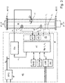
- the density measuring device comprises a measuring transducer MW of the vibration type which can be connected or connected via an inlet end # 111 and an outlet end # 112 to the process line, for example designed as a pipeline, which transducer in operation corresponds to the medium to be measured, such as a low-viscosity liquid and / or a highly viscous paste and / or a gas is flowed through.
- the transducer MW generally serves to generate mechanical reaction forces in the medium flowing through, namely in particular inertia forces dependent on the density, but possibly also Coriolis forces dependent on a mass flow rate and / or friction forces dependent on a viscosity, which can be detected by sensors, thus have a measurable effect on the transducer.
- the density ⁇ and possibly also the mass flow rate m and / or the viscosity ⁇ of the medium can be measured.
- the transducer MW is also set up to generate at least one primary signal which has at least one characteristic signal parameter dependent on the density, in particular a signal frequency dependent on the density and / or a signal amplitude dependent on the density and / or one dependent on the density Phase angle.
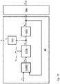
- the density measuring device comprises a measuring device electronics ME, which is electrically connected to the measuring transducer MW, especially during operation from an external connection cable and / or by means of an internal energy storage device, for generating measured values (X ⁇ ) or measuring values representing the density.
- the measuring device electronics ME formed, for example, by means of at least one microprocessor and / or by means of a digital signal processor (DSP) can, as in FIG Fig. 1 indicated, for example in a single, possibly also chambered, electronics housing 200 of the density measuring device.
- Said electronics housing 200 can, depending on the requirements placed on the density measuring device, also be designed, for example, to be impact-resistant and / or also to be explosion-proof and / or hermetically sealed.
- the measuring device electronics ME as in Fig. 3 shown schematically in the manner of a block diagram, a driver circuit Exc serving to control the transducer and a measurement and evaluation circuit ⁇ C which processes primary signals from the transducer MW, for example formed by means of a microprocessor and / or communicating with the driver circuit Exc during operation which generates measured values representing at least the density, but possibly also the instantaneous or a totalized mass flow rate and / or the viscosity, during operation.
- the measuring device electronics can also be designed in such a way that, with regard to the circuit structure, it uses one of the measuring device electronics known from the prior art mentioned at the beginning, for example US-B 63 11 136, or, for example, also a measuring transducer on the part of the applicant , e.g. under the designation "PROMASS 83F" or at http://www.de.endress.com/#product/83F, corresponds to the Coriolis mass flow / density measuring device offered.
- the measured values generated by means of the measuring device electronics ME can also be displayed, for example, on site, namely directly at the measuring point formed by means of the density measuring device.
- the density meter can be on site, as well Fig.
- a display and operating element HMI that communicates with the measuring device electronics, possibly also portable, such as an LCD, OLED or TFT display placed in the electronics housing 200 behind a window provided therein, as well as a corresponding input keyboard and / or a touch screen.
- the measuring device electronics ME which can also be (re) programmed or remotely parameterized, for example, can advantageously be designed in such a way that, when the density measuring device is in operation, it can be operated with an electronic data processing system superordinate to it, for example a programmable logic controller (PLC), a personal computer and / or a workstation, via a data transmission system, for example a field bus system such as FOUNDATION FIELDBUS, PROFIBUS, and / or wirelessly by radio, can exchange measurement and / or other operating data, such as current measured values, system diagnostic values, system status messages or else Setting values used to control the density measuring device.
- PLC programmable logic controller
- PROFIBUS PROFIBUS
- FIG. 3 Shown embodiment shown, in particular the measuring and evaluation circuit ⁇ C by means of a microcomputer provided in the measuring device electronics ME, for example realized by means of a microprocessor or a digital signal processor (DSP), and by means of program programs implemented accordingly and running therein. Codes be implemented.
- the program codes as well as other operating parameters useful for controlling the density measuring device, such as setpoints for controllers or controller algorithms implemented by means of the measuring device electronics can, for example, be persistently stored in a non-volatile data memory EEPROM of the measuring device electronics ME when starting the same into a, for example, integrated in the microcomputer, volatile data memory RAM are loaded.
- Microprocessors suitable for such applications are, for example, those of the TMS320VC33 type, as offered on the market by Texas Instruments Inc.
- the measuring device electronics ME can be designed in such a way that it can be fed from an external energy supply, for example also via the aforementioned field bus system.
- the measuring device electronics ME can, for example, have such an internal energy supply circuit NRG for providing internal supply voltages U N , which during operation is fed by an external energy supply provided in the aforementioned data processing system via the aforementioned fieldbus system.
- the density measuring device can for example be designed as a so-called four-wire device, in which the internal power supply circuit of the measuring device electronics ME by means of a first pair of lines with an external power supply and the internal communication circuit of the measuring device electronics ME by means of a second pair of lines with an external data processing circuit or to an external data transmission system.
- the measuring device electronics can, however, also be designed in such a way that, as also mentioned in the introduction, among other things US-B 72 00 503 , the US-B 77 92 646 shown, can be electrically connected to the external electronic data processing system by means of a two-wire connection configured, for example, as a 4-20 mA current loop and is supplied with electrical energy via it, as well as measured values for the data processing system can transfer.
- the measuring device electronics ME which can also be (re) programmed on site and / or via the communication system, can be connected to the one corresponding - for example, one of the relevant industrial standards, such as IEC 61158 / IEC 61784, compliant - have communication interface COM for data communication, e.g. for sending measurement and / or operating data, including the measured values representing the density and possibly also the the measured values representing viscosity, mass flow or mass flow rate, to the already mentioned programmable logic controller (PLC) or a higher-level process control system and / or to receive setting data for the density measuring device.
- PLC programmable logic controller
- connection lines which are routed from the electronics housing 200, for example via cable bushings, into a transducer housing 100 of the transducer and are laid at least in sections within the same transducer housing 200.
- the connection lines can be designed at least partially as electrical, at least in sections in electrical insulation-sheathed line wires, for example in the form of "twisted-pair" lines, ribbon cables and / or coaxial cables.
- the connection lines can also be formed, at least in sections, by means of conductor tracks of a, for example, flexible, optionally also lacquered printed circuit board, cf. also those mentioned at the beginning US-B 67 11 958 or US-A 53 49 872 .
- the measuring transducer comprises an inner part which is arranged in a measuring transducer housing 100 and which actually effects the physical-electrical conversion of the density and possibly also the viscosity or the mass flow rate.
- a measuring transducer housing 100 that hermetically seals the interior of the transducer MW from the surrounding atmosphere, and possibly also serves as a pressure- and / or explosion-proof protective cover, can for example consist of a - smooth or corrugated - stainless steel sheet or also a Be made of plastic.
- the transducer housing 100 as also in FIG Fig.
- a hermetically sealed and / or pressure-tight bushing, for example produced by means of glass and / or plastic potting, for electrical connection lines laid between the measuring device electronics and the measuring transducer can furthermore be arranged inside the connecting piece.
- the inner part, and consequently the measuring transducer MW formed therewith basically comprises at least one - im in the Fig. 4 and 5
- the exemplary embodiment shown is namely a single measuring tube 10, which is curved at least in sections, with a lumen surrounded by a tube wall.
- the tube wall of the at least one measuring tube can for example consist of a metal, for example titanium or a titanium alloy, tantalum or a tantalum alloy, zirconium or a zirconium alloy, a stainless steel or a nickel-based alloy, or, for example, also of silicon.
- the at least one measuring tube 10 extends, as from the Fig.
- the at least one measuring tube 10 can be shaped in such a way that the aforementioned center line, as is quite common with measuring transducers of the type in question, lies in an imaginary tube plane of the measuring transducer.
- the useful vibrations of the at least one measuring tube 10 are designed so that the at least one measuring tube 10 is made to vibrate during operation in such a way that the same measuring tube 10 executes oscillatory movements over the entire oscillation length about an imaginary oscillation axis that leads to one of the two measuring tube ends 11 #, 12 # imaginary connecting imaginary connecting axis is parallel or coincident.
- the useful vibrations can, for example, correspond to a vibration form of a natural bending vibration mode, for example a bending vibration fundamental mode, of the at least measuring tube, and thus be bending vibrations about the same vibration axis.
- the at least one measuring tube 10 can also advantageously be shaped and arranged in the measuring transducer in such a way that the aforementioned connecting axis essentially runs parallel to an imaginary longitudinal axis L of the measuring transducer connecting the inlet and outlet end of the measuring transducer, possibly also with the same Longitudinal axis L coincides.
- the transducer MW is intended to be used for a large number of different applications, especially in the field of industrial measurement and automation technology, it is also provided that the at least one measuring tube has a caliber (inner diameter) that is greater than 1 mm, especially greater than 10 mm, sometimes even more than 80 mm.
- MEMS microsystem technology
- the caliber of the at least one measuring tube as also mentioned in the above-mentioned US-B 64 77 901 , US-B 66 47 778 or. US-B 70 59 176 mentioned, but also smaller than 1 mm, especially also smaller than 0.5 mm, selected.
- the inner part of the transducer can also have a mechanical measuring tube with the (single) - here curved - measuring tube 10 coupled, for example also similar to the measuring tube 10 U- or V-shaped, counter-oscillator 20 to minimize disturbing influences acting on the inner part as well as to reduce the total vibration energy emitted by the respective transducer to the connected process line.
- the counter-oscillator 20 is laterally spaced from the measuring tube 10 and is fixed on the inlet side to form a first coupling zone defining the aforementioned first measuring tube end 11 # and forming a second coupling zone defining the aforementioned second measuring tube end 12 # on the outlet side.
- the counter-oscillator 20 - running essentially parallel to the measuring tube 10 here - is advantageously produced from a metal, such as steel, titanium or zirconium, which is compatible with the measuring tube 10 in terms of thermal expansion behavior. As in Fig.
- the counter-oscillator 20 can, for example, by means of plates arranged on the left and right of the measuring tube 10 or also on the left and right of the Measuring tube 10 arranged (dummy) tubes be formed.
- the counter-oscillator 20 - such as, for example, in that mentioned US-B 66 66 098 proposed - also be formed by means of a single (dummy) tube running parallel to the side of the measuring tube.
- the counter-oscillator 20 in the exemplary embodiment shown here is held by means of at least one inlet-side first coupler 31 on the first measuring tube end 11 # and by means of at least one outlet-side second coupler 32, in particular essentially identical to the coupler 31, on the second measuring tube end 12 #.
- simple junction plates can serve as couplers 31, 32, which are fastened to the measuring tube 10 and counter-oscillator 20 in a corresponding manner on the inlet side and outlet side, respectively.
- a completely closed box or possibly also partially open frame is used as a coupler 31 or as a coupler 32, by means of node plates spaced apart from one another in the direction of the imaginary longitudinal axis L of the transducer together with protruding ends of the counter-oscillator 20 on the inlet side and outlet side.
- the measuring tube 10 can also be seen via a straight first connecting pipe section 11 that opens out on the inlet side in the area of the first coupling zone and via a straight second connecting pipe section 12 that opens out on the outlet side in the area of the second coupling zone, in particular essentially identical to the first connecting pipe section 11 correspondingly connected to the process line supplying or discharging the medium, an inlet end of the inlet-side connecting pipe section 11 practically forming the inlet end of the measuring transducer and an outlet end of the outlet-side connecting pipe section 12 forming the outlet end of the measuring transducer.
- the measuring tube 10 and together with the two connecting tube pieces 11, 12 can be made in one piece, so that for their production, for example, a single tubular semi-finished product made of a material customary for such transducers, such as stainless steel, titanium, zirconium, tantalum or corresponding alloys of it, can serve.
- a single tubular semi-finished product made of a material customary for such transducers, such as stainless steel, titanium, zirconium, tantalum or corresponding alloys of it, can serve.
- a single tubular semi-finished product made of a material customary for such transducers, such as stainless steel, titanium, zirconium, tantalum or corresponding alloys of it, can serve.
- a single tubular semi-finished product made of a material customary for such transducers, such as stainless steel, titanium, zirconium, tantalum or corresponding alloys of it, can serve.
- the two connecting pipe pieces 11, 12 are aligned with one another and with an imaginary longitudinal axis L of
- the two connecting pipe pieces 11, 12 are aligned with one another in such a way that they run essentially parallel to the imaginary longitudinal axis L or to the aforementioned imaginary oscillation axis or that the connecting pipe pieces 11, 12 both to the longitudinal axis L as well as to each other essentially cursing. Since the two connecting pipe pieces 11, 12 in the exemplary embodiment shown here are essentially straight over their entire length, they are accordingly aligned with each other and with the imaginary longitudinal axis L as a whole.
- the transducer housing 100 is fixed, especially rigid, to an inlet end of the inlet-side connecting pipe section 11 which is distal with respect to the first coupling zone and to an outlet end of the outlet-side connecting pipe section 12 which is distal with respect to the second coupling zone , in such a way that the entire inner part - formed here by means of measuring tube 10 and counter-oscillator 20 - is not only completely encased by the transducer housing 100, but is also held in the transducer housing 100 so that it can vibrate due to its own weight and the spring action of the two connecting pipe sections 11, 12.
- a first connection flange 13 for connection to a medium of the process line feeding the measuring transducer is on the inlet side of the measuring transducer and a second connection flange 14 on the outlet side intended for a line segment of the process line leading away from the measuring transducer.
- the connection flanges 13, 14 can, as is quite common in the case of measuring transducers of the type described, also integrated into the measuring transducer housing 100 at the end, namely designed as an integral part of the measuring transducer housing.
- first connection flange 13 can be molded onto the inlet-side connecting pipe section 11 at its inlet end and the second connection flange 14 can be molded onto the outlet-side connecting pipe section 12 at its outlet end by means of a corresponding soldered or welded connection.
- the measuring device electronics ME comprise a driver circuit Exc and the measuring transducer MW at least one electrically connected to the driver circuit Exc , electromechanical vibration exciter 41.
- the at least one - here the only one acting on the at least one measuring tube 10 - vibration exciter 41 can be placed, for example, in such a way that, as in FIG Fig. 4 and 5 indicated and, as is quite common with transducers of the type in question, acts in the middle of the measuring tube, namely formed in the region of half an oscillation length, on the at least measuring tube 10.
- the at least one measuring tube 10 is actively stimulated during operation by means of the at least one vibration exciter 41, at least temporarily, to useful vibrations that are predominantly or exclusively designed as flexural vibrations around the imaginary vibration axis mentioned.
- the at least one measuring tube 10 is excited by means of the vibration exciter 41 to such flexural vibrations in which the at least one measuring tube 10 oscillating around the same axis of oscillation - for example in the manner of a cantilever clamped on one side - at least partially bends according to an oscillation shape of a natural bending oscillation fundamental mode, such that the bending oscillations, and therefore the useful oscillations of the measuring tube, only have an inlet-side vibration node in the area of the inlet-side coupling zone defining the inlet-side measuring tube end 11 # and an outlet-side oscillation zone defining the outlet-side measuring tube end 12 # exhibit.
- the vibration exciter 41 is designed as an electrodynamic vibration exciter, namely constructed in the manner of a voice coil, in such a way that the vibration exciter 41 has a cylindrical excitation coil, which is electrically connected to the driver circuit Exc, and therefore to the measuring device electronics ME formed therewith has a permanent magnetic armature, therefore a magnetic field, and that the same magnetic field interacts with an (alternating) magnetic field generated by means of the excitation signal in the excitation coil in a manner causing relative movements of armature and excitation coil.
- the excitation coil can be fixed to the counter-oscillator 20 and the armature from the outside to the measuring tube 10, for example.
- the vibration exciter 41 can, for example, also be an electrostatic one, namely by means of a capacitor, of which a first capacitor plate on the measuring tube and a second capacitor plate on the counter-oscillator or - not least in the case of measuring transducers formed by means of a measuring tube with a very small caliber of less than 1 mm Can usually be fixed on the respective transducer housing, formed vibration exciter or designed as a piezoelectric vibration exciter.
- the actively excited useful vibrations are bending vibrations of the measuring tube
- these can be used in the case of the in Fig. 4 and 5
- a measuring transducer formed by means of measuring tube 10 and counter-oscillator 20 it can advantageously be designed in such a way that measuring tube 10 executes oscillatory movements that periodically change a relative distance between measuring tube 10 and counter-oscillator 20 with a useful frequency f N.
- the counter-oscillator 20 can also be excited to simultaneous cantilever oscillations, for example in such a way that it has oscillations at the same frequency as the useful oscillations, for example flexural oscillations around a virtual axis of oscillation parallel to the mentioned longitudinal axis L, which are at least partially, in particular in the area of the point of application formed by means of the vibration exciter 41, and / or at least temporarily, namely when the measuring tube is not flowed through, essentially in phase opposition to the measuring tube 10.
- the oscillations of the counter oscillator 20 can be designed in such a way that they are of the same modal order as the useful oscillations. In other words, the measuring tube 10 and the counter-oscillator 20 can then move in the manner of tuning fork prongs oscillating against one another.
- the driver circuit Exc and therefore the measuring device electronics of the density measuring device according to the invention, is also set up to generate an (analog) electrical excitation signal e 1 and to feed electrical power E exc into the vibration exciter 41 by means of the same excitation signal e 1.
- the excitation signal e 1 can, as is quite common in density measuring devices of the type in question, be an at least temporarily harmonic electrical alternating signal with an impressed alternating voltage and / or an impressed alternating current.
- a digital phase locked loop PLL
- a current intensity of the excitation signal which determines an amount of the same excitation forces, for example by means of a corresponding, possibly digital current regulator the driver circuit can be set appropriately.
- the excitation signal e 1 can also be generated, for example, based on a digital control signal e 1D initially generated by the measurement and evaluation circuit ⁇ C, by means of which, during operation, a power amplifier that is contained in the driver circuit Exc and ultimately provides the excitation signal e 1 is controlled.
- the digital control signal e 1D can, for example, be a digital signal generated by means of a numerically controlled oscillator (NCO), for example also sinusoidal.
- NCO numerically controlled oscillator
- the measuring device electronics ME can, for example, also be designed to regulate the excitation signal in such a way that the useful vibrations have a constant amplitude that is largely independent of the density ⁇ or the viscosity ⁇ of the respective medium to be measured.
- the vibration exciter 41 in turn serves or is set up to use the same excitation signal e1 to feed electrical power E exc into a (force) point of application formed by means of the vibration exciter 41 on the at least one measuring tube and deflecting or deflecting it in the manner described above.
- the (naturally vectorial) driving force F for the purpose of a targeted excitation of the useful vibrations is designed so that it is a useful force component F introduced into the at least one measuring tube 10 N , namely a periodic force component which changes with an excitation frequency corresponding to the useful frequency f N and ultimately causes the useful vibrations.
- driver circuits suitable for the density measuring device suitable for the density measuring device according to the invention
- their driver circuit is, for example, also designed in such a way that the respective useful vibrations are regulated to a constant amplitude, that is to say also largely independent of the density ⁇ or the viscosity ⁇ .
- the measuring transducer further comprises an additional pair of connecting wires to the measuring device electronics, for example by means of an additional pair of connecting wires, also not shown here for reasons of clarity ME electrically connected first oscillation sensor 51.
- the oscillation sensor 51 is set up here to detect oscillation movements of the at least one measuring tube - not least oscillating movements corresponding to the useful oscillations or movements of oscillations of the measuring tube with useful frequency f N - and converting them into a representing, as a To convert the primary signal of the transducer serving first vibration measurement signal s 1 , for example with a voltage corresponding to a speed of the recorded vibration movements or a voltage corresponding to the recorded vibration movements ondating current. Due to the fact that the at least one measuring tube 10 carries out the mentioned useful vibrations, i.e.
- the vibration measurement signal s 1 generated by the vibration sensor 51 has a signal frequency corresponding to the useful frequency or contains the vibration measurement signal s 1 - for example in the case of a broadband and / or multimodal vibration excitation by disturbances introduced from the outside via the connected pipeline and / or via the medium flowing through - at least one corresponding useful signal component, namely a periodic signal component with a the signal frequency corresponding to the useful frequency f N.
- the vibration sensor 51 can, for example, be designed as an electrodynamic vibration sensor, namely constructed in the manner of a plunger coil, so that the vibration sensor 51 is electrically connected to a counter-vibrator 20 and at the same time to the measuring and evaluation circuit, i.e.
- the vibration sensor 51 can, for example, also be designed as a capacitive vibration sensor formed by means of a capacitor, of which a first capacitor plate can be fixed to the measuring tube and a second capacitor plate to the counter-oscillator.
- the vibration sensor 51 is arranged at a distance from the vibration exciter 41 along the at least measuring tube, for example in this way that so that the inlet-side vibratory movements of the measuring tube, namely - as in Fig. 3 Schematically shown - Vibration movements of the at least one measuring tube 10 at a measuring point located between the measuring tube end # 11 and the vibration exciter 51, although they can be detected from both the measuring tube end # 11 and the vibration exciter 51.
- the vibration measurement signal s 1 generated by means of the vibration sensor 51 is, as also in FIG Fig. 3 shown, the measuring device electronics ME and initially fed to an input circuit FE, which is used to first suitably preprocess the vibration measurement signal s 1 , namely to prepare it for a digital signal processing on which the actual density measurement is based, for example to pre-amplify, filter and digitize it .
- the input circuit FE as well as the measuring and evaluation circuit ⁇ C can also be used in conventional density or Coriolis mass flow / density measuring devices for the purpose of converting primary signals supplied by means of a transducer of the vibration type or for the purpose of determining the density, possibly also from
- the measured values representing the mass flow rate and / or the viscosity that have already been used and established circuit technologies can be used, for example also those according to the prior art mentioned at the beginning.
- the measurement and evaluation circuit ⁇ C as also in the one mentioned above US-B 63 11 136 shown or the aforementioned transducers of the measuring device series "PROMASS 83F" are realized, Formed by means of at least one microprocessor, and therefore provided for processing digital signals, the measuring device electronics are also set up to convert the vibration signal s 1 into a corresponding digital vibration measurement signal s 1D by means of an analog-to-digital converter A / D and then to process or evaluate digitally.
- the measuring device electronics of the density measuring device according to the invention are set up in particular to use the vibration measurement signal s 1 , for example also a digital vibration measurement signal s 1D obtained therefrom, to present the density of the medium carried in the transducer Generate density measurement value X ⁇ or update it repeatedly.
- the measuring and evaluation circuit, and therefore the measuring device electronics ME of the density measuring device according to the invention is also set up, inter alia, to determine a frequency measurement value X f representing the useful frequency f N or to update it repeatedly during operation, for example using the excitation signal e 1 and / or the at least one vibration measurement signal s 1 , as well as the same frequency measurement value X f when determining the density measurement value X ⁇ or the density measurement values.
- the measuring device-specific coefficients A and B listed in the same calculation rule can in turn, in the manner known per se to the person skilled in the art, by measuring the density measuring device using different media, for example also in each case kept at a temperature corresponding to the mentioned reference temperature, with different densities, for example Air or water and / or glycerine, are determined in advance, for example in the course of a wet calibration carried out in the manufacturer's works.
- the useful vibrations of the at least one measuring tube 10 excited to determine the density are, due to its natural vibration properties, designed such that - as in FIG Fig. 6 or 7 by means of a so-called pointer model or also a pointer diagram illustrates a speed response V N of the at least one measuring tube 10, namely a speed of the oscillatory movements of the at least one measuring tube 10 at the point of application, which changes over time with the useful frequency f N , compared to the useful force component F N of the driving force is phase shifted by a certain phase shift angle ⁇ N , which is dependent on the actually set excitation frequency, and therefore on the actually set useful frequency f N.
- the aforementioned dependence of the speed response V N on the useful force component F N is such that in the event that the set excitation frequency - as is usual with conventional density measuring devices of the type in question - corresponds to an instantaneous resonance frequency of the at least one measuring tube 10, i.e. a resonance condition ( ) is fulfilled, namely the phase shift angle ⁇ N is approximately zero ( Fig.
- the phase shift angle ⁇ N is less than 0 °, for example about -50 ° to -70 ° ( Fig. 7 ).
- the excitation or the useful frequency can be approximately between 490.05 Hz and 490.5 Hz at a phase shift angle ⁇ N of between -50 ° and -70 °.
- the driving force F again or their Nutzkraftkomponente F N can in regard to the expert known per se, for example by means of an appropriately conditioned current intensity or voltage level of the electrical excitation signal e1 with respect to their amplitude and same by adjusting a signal frequency of the excitation signal e 1 of their Excitation frequency can be precisely adjusted. Accordingly, according to a further embodiment of the invention, the measuring device electronics are set up so that the driving force F i is not finally to adjust their useful force component F N by changing a signal frequency of the excitation signal e 1.
- the same control signal e 1D - possibly taking into account an actual transmission behavior of the driver circuit Exc and / or the at least vibration exciter 41 - with regard to both the frequency and also the amplitude can already be adjusted appropriately to the desired useful force component by means of the measurement and evaluation circuit ⁇ C.
- a characteristic of the useful frequency f N used in each case for measuring the density ⁇ in density measuring devices of the type in question is that it is usually an oscillation frequency at which the phase shift angle ⁇ N between the speed response V N and the useful force component F.
- N of the driving force F is set to a correspondingly predetermined phase setpoint value, or vice versa, which results after the phase shift angle ⁇ N , for example by continuously or quasi-continuous or step-by-step change of the excitation frequency by means of the measuring device electronics at least for one predetermined phase control interval, namely required for the actual measurement of the useful frequency, has been steadily adjusted to the respective phase setpoint value.
- conventional density measuring devices typically use resonance vibrations, i.e. those vibrations as useful vibrations in which the phase shift angle ⁇ N is at least approximately 0 ° or, ideally, is exactly zero, in which the aforementioned resonance condition ( ) is fulfilled (cf. Fig. 6 ).
- the actual duration of the respectively required phase control interval is not least due to a dynamic, namely a temporal behavior of the means of the vibration exciter, the at least one measuring tube, the at least one vibration sensor and the measuring device electronics, in particular the measuring and evaluation circuit and the driver circuit , overall formed mechatronic system on the one hand, as well as a processing speed or update rate with which the measuring and evaluation circuit can determine the useful frequency based on the vibration signal and generate the corresponding frequency measured values.
- the update rates for the frequency measured values have so far typically been in the range from approximately 100 Hz to approximately 200 Hz.
- the measuring device electronics ME of the density measuring device are also set up to adjust the driving force required for the active excitation of the useful vibrations by means of the vibration measurement signal s 1 and the excitation signal e 1, in such a way that during a predetermined phase control interval ⁇ t ⁇ , for example 10 ms or longer, the same phase shift angle ⁇ N is set to a predetermined phase setpoint ⁇ N_SOLL .
- An actual required duration of the phase control interval ⁇ t ⁇ - which is of course repeatedly passed through by the measuring device electronics during operation - depends on the one hand on the speed at which the usable frequency can be adjusted to a time-changing density during operation and on the other hand, among other things, according to how many oscillation periods of the useful oscillations are actually recorded for a single frequency measurement value or how many oscillation periods of the oscillation measurement signal are actually to be evaluated.
- the measuring device electronics are also set up to regulate the phase shift angle ⁇ N to a predetermined phase setpoint ⁇ N_SOLL, namely to set it to a corresponding phase value or to keep it at a corresponding phase value, in such a way that the phase shift angle ⁇ N at constant density by less than ⁇ 1% of the same phase target value ⁇ N_SOLL and / or by less than ⁇ 2 ° around the same phase target value ⁇ N_SOLL fluctuates or ideally during the entire phase control interval and / or not at the moment varying density ⁇ is kept constant at that nominal phase value ⁇ N_SOLL , and is therefore stationary.
- the adjustment of the phase shift angle ⁇ N to the phase target value ⁇ N_SOLL can be done by changing a signal frequency of the excitation signal e1 until the phase shift angle ⁇ N has reached a predetermined phase target value ⁇ N_SOLL , for example in such a way that the measuring device -Electronics in the case of a phase shift angle ⁇ N that is set too low, namely smaller than the phase setpoint ⁇ N_SOLL, and in such a way that the measuring device electronics in the case of an excessively large, namely greater than the phase setpoint ⁇ N_SOLL set phase shift angle ⁇ N same signal frequency increased.
- a phase value for the currently actually set phase shift angle ⁇ N can in turn by means of the measurement and evaluation circuit ⁇ C, for example based on a determined between the vibration measurement signal s 1 and the excitation signal e 1 , in the measuring device electronics of density measuring devices in question standing type in operation regularly take place anyway existing phase angle.
- the phase setpoint ⁇ N_SOLL can, if necessary - for example for the purpose of measuring other measured variables, such as a viscosity ⁇ , of the medium carried in at least one measuring tube 10 - also be changeable, so that the measuring device electronics do the measuring the specified phase setpoint value ⁇ N_SOLL are temporarily replaced by another, for an additional device function that deviates from the measurement of the density, according to the specified phase setpoint value, so that the measuring device electronics afterwards adjusts the phase shift angle ⁇ N to the same phase setpoint.
- other measured variables such as a viscosity ⁇
- the useful vibrations - in contrast to conventional density measuring devices used up to now - are designed so that the phase shift angle ⁇ N for the purpose of measuring the useful frequency f N required to determine the density by means of the measuring device electronics is less than -30 ° and greater than -70 °, or vice versa, that the useful frequency f N is set by means of the measuring device electronics so that the same useful frequency f N is more than 1.00001 times, nevertheless less than 1.001 -fold of a resonance frequency f R of the at least one measuring tube, but also does not correspond to any other resonance frequency of the at least one measuring tube 10, so the determination of the density is based on useful vibrations for which the resonance condition ( ) namely is not fulfilled.
- phase shift angle ⁇ N or such a useful frequency f N having useful oscillations can namely - in Fig. 8 and FIG. 9 based on diagrams illustrating the dependence of the speed response V N on the selected excitation frequency (amplitude frequency response) or in Fig.
- phase frequency response that illustrates the dependence of the useful frequency f N on the selected phase shift angle ⁇ N - dependence of the excitation or useful frequency f N (corresponding to the phase shift angle ⁇ N to be set or set) also on a momentary viscosity ⁇ of the medium, resulting from a dependency of the phase shift angle ⁇ N (set according to the phase setpoint value) on an instantaneous damping counteracting the stimulated useful vibrations, can be almost eliminated, or at least reduced to a considerable extent.
- a diagram phase frequency response
- phase shift angle ⁇ N is particularly pronounced in the range of the resonance frequency f R , which is preferably used in conventional density measuring devices of the type in question for measuring the density, while the same dependence on smaller, namely negative, phase shift angles ⁇ N , therefore with excitation or useful frequencies f N lying in the frequency range slightly above the same resonance frequency f R decreases or is practically no longer measurable.
- the resonance frequency f R - a resonance frequency f R for that for density measuring instruments of the type in question - not least also used in conventional density measuring devices up to now for the determination of density as a useful frequency regularly striven for high measurement accuracy have a considerable dependence also on the damping of the useful vibrations or the viscosity ⁇ of the respective medium causing them.
- the measuring device electronics of the density measuring device are accordingly also set up to use the vibration measurement signal s 1 and the excitation signal e 1 to generate the driving force, in particular adjust the useful force component or its excitation frequency so that the phase shift angle ⁇ N , as in Fig.
- the useful frequency has a frequency value during the phase control interval ⁇ t ⁇ , which corresponds to more than 1.00001 times, nevertheless less than 1.001 times an instantaneous frequency value of a resonance frequency f R of the at least one measuring tube 10.
- the measuring device electronics are set up to determine the at least one frequency measurement value X f based on the vibration measurement signal s1 obtained during the phase control interval, such that the same frequency measurement value X f is the useful frequency for the phase control interval ⁇ t ⁇ , and to generate the density measurement value X ⁇ using the same frequency measurement value X f.
- a phase shift angle ⁇ N suitable for the respective transducer or the density measuring device formed therewith can be determined in advance, for example, by computer-aided simulation calculation and / or experimentally, for example by, as inter alia, also from the Fig. 10 apparent, for two or more reference media with differing viscosity, nevertheless at least approximately the same density, respectively associated frequency responses are determined and based on the same frequency responses - for example by determining an intersection of a number of frequency responses or a mean intersection formed by a number of such adjacent intersection points , a, im in Fig. 10
- the diagram shown is set at about -52 °, phase value with a minimal dependence on the viscosity as phase setpoint ⁇ N_SOLL .
- the measuring device electronics also set up to keep a signal frequency of the excitation signal e 1 during the entire phase control interval at a frequency value that is not less than 1,0001 times a resonance frequency f R of the at least a measuring tube, for example namely a lowest resonance frequency and / or a resonance frequency corresponding to a bending vibration fundamental mode, and is not more than 1.01 times the same resonance frequency.
- the setting of the frequency of the excitation signal, hence the useful frequency f N can, as is quite common with density measuring devices of the type in question, using a digital phase control loop provided in the measuring device electronics, for example implemented by means of the measuring and evaluation circuit ⁇ C (PLL) take place, which uses the aforementioned relationship between the instantaneous excitation or useful frequency f N and the instantaneous phase shift angle ⁇ N to adapt the control signal e 1D to the instantaneous vibration properties of the inner part formed by means of the at least one measuring tube 10.
- PLL measuring and evaluation circuit
- the phase shift angle ⁇ N can be adjusted to the phase setpoint ⁇ N_SOLL, for example, by the phase control loop changing a signal frequency of the excitation signal e1 until through the phase control loop based on the mentioned vibration measurement signal s 1 or using one obtained therefrom digital auxiliary signal, such as the aforementioned digital vibration measurement signal s 1D , a match between the phase shift angle ⁇ N and the specified phase target value ⁇ N_SOLL is detected or by the phase control loop not changing the same signal frequency of the excitation signal e1 if the phase shift angle ⁇ N with the phase setpoint ⁇ N_SOLL is determined.
- a digital phase control loop suitable for use in a density measuring device according to the invention for regulating the excitation frequency, hence the useful frequency f N can have a phase comparator COMP, by means of which a recurring comparison of an instantaneous phase position of the digital vibration measurement signal s 1D applied to a first input with an instantaneous phase position of the control signal e 1D fed back to a second input - here designed as a sinusoidal digital signal - and by means of which, based on the comparison, an error signal Err ⁇ is generated, which signals whether or to what extent the phase positions of the two inputs applied signals - here namely the digital vibration measurement signal s 1D and the digital control signal e 1D - differ from one another.
- the error signal Err ⁇ is then fed to a frequency controller CTRL, which is used to convert the error signal Err ⁇ , taking into account a phase control setpoint ⁇ N_SOLL preset for the frequency controller CTRL, for example permanently programmed, into a numerical control value that can be tapped at an output of the frequency controller CTRL a Represents the signal frequency with which the control signal e 1D is currently to be output.
- the phase control setpoint ⁇ N_SOLL corresponds to a numerical phase value that is determined in advance based on the phase setpoint ⁇ N_SOLL actually aimed for for the phase shift angle ⁇ N , and also taking into account any others by the density measuring device - for example, namely by the vibration exciter, the At least one vibration sensor and / or the measuring device electronics, in particular its measuring and evaluation circuit or its driver circuit, - caused influences on a phase shift between the excitation signal e 1 and the at least one vibration measurement signal s 1 .
- the structure and mode of operation of the vibration exciter must be taken into account when calculating the phase control setpoint ⁇ N_SOLL, not least in such a way that for the case mentioned, for example, that the vibration exciter 41 is designed in the manner of a voice coil, the useful excitation component of the excitation signal e 1 is at least approximately periodic current with the useful force component F N is at least approximately in phase with the same frequency, but has a periodic voltage which is identical in frequency to the useful force component F N , but is phase-shifted by an amount in the order of 90 °, or for the other case mentioned, that the vibration exciter comes from the electrostatic Type, namely formed by means of a capacitor, an electrical voltage of the excitation signal e 1 a periodic voltage component which is at least approximately identical in frequency and phase to the useful force component F N, nevertheless one to the useful force component component F N has the same frequency, but has a periodic current phase-shifted by an amount of the order of magnitude of 90 °.
- the structure and mode of operation of the at least one vibration sensor 51 must also be taken into account.
- the vibration measurement signal s 1 has a the speed response V N of the at least one measuring tube has a frequency and at least approximately in phase periodic voltage
- the vibration measurement signal s 1 for the other case mentioned, that the vibration sensor is formed by means of a capacitor has the same frequency as the speed response of the at least one measuring tube , nevertheless has periodic current phase-shifted by approximately + 90 ° with respect to the speed response.
- the signal transmission behavior specific to the measuring device electronics is also a resulting phase frequency response of the measuring device electronics in the calculation of the phase control setpoint ⁇ N_SOLL to be included accordingly or the measuring device electronics, not least the mentioned ones Input circuit, the measurement and evaluation circuit as well as the driver circuit, naturally inherent group delays associated with additional, namely delay-related phase shifts such as the aforementioned digital vibration measurement signal s 1D relative to the vibration measurement signal s 1 or also of the excitation signal e1 relative to the aforementioned digital control signal e 1D to be included accordingly in the phase control setpoint ⁇ N_SOLL.
- phase control setpoint ⁇ N_SOLL actually suitable for the density measuring device can, for example, be measured experimentally in the course of a calibration of the same density measuring device carried out in the manufacturer's plant and then stored in the mentioned non-volatile memory EEPROM of the measuring device electronics.
- the signal frequency representing control value output of the frequency controller CTRL is also transferred to an - here numerically controlled - oscillator NCO, which supplies the digital control signal e 1D sent to the driver circuit at an output with a signal frequency determined by the current control value.
- NCO numerically controlled - oscillator
- control value at the output of the frequency controller CTRL can also serve, for example, as a frequency measured value X f or to a calculation rule (3) that generates the density measured value X ⁇ , for example the above-mentioned calculation rule (3) for determining the density measured value X ⁇ executing and / or by means of a calculation routine executed by a microprocessor of the measuring device electronics, arithmetic unit CALC can be transferred.
- a phase-locked loop however, other frequency control circuits suitable for setting the useful frequency f N and known per se to the person skilled in the art can of course also be used, for example those that are based on positive feedback of the excitation signal e 1 to the at least one vibration measurement signal s 1 .
- the density measuring device can, if necessary and as is quite common with density measuring device of the type in question, furthermore a temperature sensor thermally coupled to at least one measuring tube 10, which - as in Fig.
- FIG Fig. 3 indicated - is set up to detect a temperature of the at least one measuring tube and convert it into a temperature measurement signal ⁇ 1 representing this, and / or a strain sensor mechanically coupled to at least one measuring tube, which - as in FIG Fig. 3 indicated - is set up to detect an expansion of the at least one measuring tube and to convert it into an expansion measurement signal ( ⁇ 1) representing it.
- the measuring device electronics can be set up to use the temperature measuring signal ⁇ 1 at least one temperature measured value X ⁇ , which represents a temperature of the at least one measuring tube, or by means of the strain measuring signal ⁇ 1, at least one expansion
- the measured value X ⁇ which represents an expansion of the at least one measuring tube or a mechanical stress built up within the at least one measuring tube as a result of the same expansion causing deformation of the transducer, and to determine the density measured value X ⁇ using the temperature Measurement value X ⁇ or the strain measurement value X ⁇ .
- the density measuring device uses the density measuring device according to the invention to determine the viscosity ⁇ of the medium carried in at least one measuring tube in addition to the density ⁇ , for example by using the measuring device -Electronics during the phase control interval based on the vibration measurement signal s 1 and / or the excitation signal determines at least one damping measurement value X D , which represents a damping that counteracts the useful vibrations of the at least one measuring tube, and - as, among other things, also in the input mentioned US-B 66 51 513 or US-B 60 06 609 proposed, based on the measured damping value X D, a measured viscosity value X ⁇ representing the viscosity ⁇ of the medium is generated.
- the viscosity ⁇ can also be determined by setting the slot frequency f N initially required for measuring the density ⁇ before and / or after the phase control interval, i.e. before or after the corresponding frequency Measured value X f has been determined, by means of the measuring device electronics, the excitation signal e 1 , and consequently the drive force F, are temporarily set so that the useful force component and the speed response now, as already mentioned or also in Fig. 6 shown the resonance condition ( ) meet, therefore the oscillation frequency of the so active excited vibrations correspond to the instantaneous resonance frequency f R.
- the measuring device electronics are set up to adjust the useful force component or its excitation frequency at least temporarily outside the phase control interval ⁇ t ⁇ , for example immediately before and / or immediately after it, in such a way that the phase shift angle ⁇ ⁇ N is not less than -5 ° and not more than + 5 °;
- the phase shift angle ⁇ ⁇ N during this time is not less than -2 ° and / or not more than + 2 °, namely that the excitation frequency of the useful force component, as is usual with conventional density measuring devices, is essentially one corresponds to the momentary resonance frequency of the at least one measuring tube, hence the useful vibrations of the at least one measuring tube outside the phase control interval ⁇ t ⁇ are temporarily resonance oscillations.
- the viscosity of the medium carried in the at least one measuring tube can be determined in the manner described above.
- the useful vibrations actively excited at the resonance frequency can also serve to target the measuring device electronics to the measuring point formed by means of the density measuring device in interaction with the connected pipeline and / or to adapt to any media changes made during operation, for example in such a way that the mentioned phase control setpoint ⁇ N_SOLL is appropriately fine-tuned, and / or to check the integrity or functionality of the density measuring device in the course of a recurring self-test, for example in such a way that one can use the Measuring device electronics diagnosed a significant deviation of one or more resonance frequencies from the preset values specified for them leads to the triggering of a warning message signaling reduced functionality and / or reduced measurement accuracy.
- the useful vibrations excited at the resonance frequency can also be used to determine a starting value from which the adjustment of the phase shift angle ⁇ ⁇ N by the measuring device electronics can be started or from which after a control deviation that is temporarily too high, for example after an abrupt one If the resonance frequency of the measuring tube changes by more than 1 Hz, for example as a result of a medium change, or in the event of a temporarily significantly fluctuating density, for example as a result of inhomogeneities temporarily formed in the medium, such as gas bubbles or solid particles entrained in a liquid, the phase shift angle ⁇ ntendedN quickly increases again the phase setpoint ⁇ N_SOLL can be brought up.
- the at least one measuring tube i.e. the mass flow or the mass flow rate ⁇ is different from zero
- the at the same time vibrating in the manner described above namely useful vibrations with a different from the current resonance frequency
- Measuring tube 10 executing the useful frequency in the medium flowing through, in addition to the inertia or friction forces, also induces Coriolis forces.
- Antinodes A momentary expression of these so-called Coriolis oscillations, which are superimposed on the stimulated useful oscillations and have the same frequency, is, in particular. with regard to their amplitudes, in particular also dependent on the instantaneous mass flow rate.
- Coriolis vibrations additionally evaluated for the purpose of measuring the mass flow rate in the case of a curved measuring tube, for example, torsional vibrations around a center line of the at least one measuring tube 10 in the range of half the center line of the at least one measuring tube 10, which are then performed in addition to the bending vibrations serving as useful vibrations, can be used Oscillation length imaginatively intersecting imaginary torsional oscillation axis are used.
- the measuring transducer also has a second vibration sensor 52, for example identical to the first vibration sensor 51, which is used to detect vibration movements of the at least one measuring tube and convert it to a second nevertheless to convert a vibration measurement signal s2 having a signal frequency corresponding to the useful frequency.
- the vibration sensor 52 like the vibration sensor 51, can be configured, for example, as an electrodynamic vibration sensor or, for example, also as a capacitive vibration sensor.
- the vibration sensors 51, 52 can also advantageously be designed and placed in the transducer in such a way that each of the vibration sensors predominantly vibrates the measuring tube 10 relative to the counter-oscillator 20, for example differentially, detected that both the oscillation measurement signal s 1 and the oscillation measurement signal s 2 represent oscillation movements of the at least one measuring tube 10 relative to the counter-oscillator 20.
- vibration sensor 52 is, as is customary with measuring transducers used in Coriolis mass flow / density measuring devices, arranged along measuring tube 10, thus at a distance from vibration sensor 51 as seen in the direction of flow on measuring tube 10, for example in such a way that, as shown in FIG Fig. 3 , 4th or 5 or their synopsis can be seen, the vibration sensor 51 is arranged on the inlet side and the vibration sensor 52 is arranged on the outlet side, and is therefore set up to detect vibration movements on the inlet side and outlet side, respectively.
- each of the vibration sensors 51, 52 is also, as is quite common with transducers of the type in question, equally spaced from the center of the at least one measuring tube 10 or from the single vibration exciter 41, which is placed here at half the vibration length.
- the measuring device electronics can be used to determine the mass flow rate in addition to the density of the medium that has flowed through the measuring tube during the phase control interval.
- the measuring device electronics are therefore also set up to additionally add a phase difference measured value X ⁇ based on both the first vibration measurement signal s1 and the second vibration measurement signal s2 during the phase control interval ⁇ t ⁇ determine which represents the phase difference ⁇ m dependent on the mass flow rate ⁇ for the phase control interval ⁇ t ⁇ ; this in particular, in order to subsequently generate a mass flow measured value X m representing the mass flow rate or the mass flow based on the phase difference measured value X ⁇ .
- the measuring device electronics are also set up to supply the useful force component F N or the phase shift angle also by means of the second vibration measurement signal s2, in particular based on both the vibration measurement signal s1 and the vibration measurement signal s2 adjust, for example in such a way that, by means of the vibration measurement signal s1 and the vibration measurement signal s2, initially a sensor sum signal representing the vibration movements of the measuring tube 10 at the location of the vibration exciter or the point of attack formed therewith or at least in phase with it, especially digital, is formed and then afterwards The same sum signal is supplied as a digital vibration measurement signal s 1D to the first input of the phase comparator COMP of the phase-locked loop (PLL) mentioned, and is therefore used to control the same phase-locked loop.
- the frequency measured value X f can also be determined using the vibration signal s2, for example also based on both the vibration measurement signal s1 and the vibration measurement signal s2.
- transducer is in the Fig. 4 and 5 representative embodiment shown only a single has curved measuring tube and at least insofar in its mechanical structure as well as its operating principle that in the aforementioned US-B 73 60 451 or.
- US-B 66 66 098 proposed or also resembles the transducers offered by the applicant under the type designation "PROMASS H", "PROMASS P" or “PROMASS S " - other transducers of the type in question can of course also be used to implement the invention, not least those with a straight and / or more than one measuring tube, roughly comparable to those mentioned in the introduction US-A 60 06 609 , US-B 65 13 393 , US-B 70 17 424 , US-B 68 40 109 , US-B 69 20 798 , US-A 57 96 011 or.
- the transducer can also have a single straight measuring tube or at least two, for example by means of an inlet-side flow splitter and an outlet-side flow splitter, if necessary also by means of at least one inlet-side coupling element and at least one outlet-side coupling element, mechanically coupled and / or structurally identical and / or have curved and / or parallel measuring tubes for guiding the medium to be measured, which vibrate at least intermittently during operation to generate the primary signals, approximately at the same frequency at a common oscillation frequency, but in antiphase, or the transducer can, for example, also use four straight lines or four be formed curved measuring tubes.
Landscapes
- Physics & Mathematics (AREA)
- General Physics & Mathematics (AREA)
- Health & Medical Sciences (AREA)
- Life Sciences & Earth Sciences (AREA)
- Chemical & Material Sciences (AREA)
- Analytical Chemistry (AREA)
- Biochemistry (AREA)
- General Health & Medical Sciences (AREA)
- Immunology (AREA)
- Pathology (AREA)
- Fluid Mechanics (AREA)
- Measuring Volume Flow (AREA)
Description
Die Erfindung betrifft ein vibronisches Dichte-Messgerät zum Messen einer Dichte, p, eines strömungsfähigen Mediums, insb. eines in einer Rohrleitung strömenden Fluids.The invention relates to a vibronic density measuring device for measuring a density, p, of a flowable medium, in particular a fluid flowing in a pipeline.
In der industriellen Messtechnik werden, insb. auch im Zusammenhang mit der Regelung und Überwachung von automatisierten verfahrenstechnischen Prozessen, zur hochgenauen Ermittlung von Dichten von in einer Prozessleitung, beispielsweise einer Rohrleitung, strömenden Medien, beispielsweise von Flüssigkeiten und/oder Gasen, oftmals jeweils mittels einer - zumeist mittels wenigstens einen Mikroprozessors gebildeten - Messgerät-Elektronik sowie einem mit nämlicher Messgerät-Elektronik elektrisch verbundenen, im Betrieb vom zu messenden Medium durchströmten Messwandler vom Vibrationstyp gebildete vibronische Dichte-Messgeräte verwendet. Solche - beispielsweise als sogenannte Vierleiter- oder auch als sogenannte Zweileitergeräte ausgebildete - Dichte-Messgeräte sind seit langem bekannt, nicht zuletzt auch ingestalt von Coriolis-Massendurchfluss-/Dichte-Messgeräten oder auch ingestalt von Viskositäts-Dichte-Messgeräten, und im industriellen Einsatz etabliert. Beispiele für solche vibronischen Dichte-Messgeräte bzw. dafür geeignete Messwandler sind u.a. in der
Das wenigstens eine Messrohr eines solchen Messwandlers ist dafür eingerichtet, im Lumen Medium zu führen und währenddessen so vibrieren gelassen zu werden, dass es Nutzschwingungen, nämlich mechanische Schwingungen um eine Ruhelage mit einer auch von der Dichte des Mediums mitbestimmten, mithin als Maß für die Dichte verwendbaren Nutzfrequenz ausführt. Bei herkömmlichen Dichte-Messgeräten dienen typsicherweise Biegeschwingungen auf einer natürlichen Resonanzfrequenz als Nutzschwingungen, beispielsweise solche Biegeschwingungen, die einem dem Messwandler immanenten natürlichen Biegeschwingungsgrundmode entsprechen, in dem die Schwingungen des Messrohrs solche Resonanzschwingungen sind, die genau einen Schwingungsbauch aufweisen. Die Nutzschwingungen sind bei einem zumindest abschnittsweise gekrümmtem Messrohr zudem typischerweise so ausgebildet, dass das nämliches Messrohr um eine ein einlassseitiges und ein auslassseitiges Ende des Messrohrs imaginär verbindenden gedachte Schwingungsachse nach Art eines an einem Ende eingespannten Auslegers pendelt, während hingegen bei Messwandlern mit einem geraden Messrohr die Nutzschwingungen zumeist Biegeschwingungen in einer einzigen gedachten Schwingungsebene sind. Es ist zudem bekannt, das wenigstens eine Messrohr zwecks Durchführung wiederkehrender Überprüfungen des Messwandlers während des Betriebs des Dichte-Messgeräts gelegentlich auch zu zeitlich andauernden Schwingungen außer Resonanz anzuregen sowie nämliche Schwingungen außer Resonanz auszuwerten, beispielsweise um, wie in der vorgenannten
Bei Messwandlern mit zwei Messrohren sind diese zumeist über ein sich zwischen den Messrohren und einem einlassseitigen Anschlussflansch erstreckenden einlassseitig Verteilerstück sowie über ein sich zwischen den Messrohren und einem auslassseitigen Anschlussflansch erstreckenden auslassseitig Verteilerstück in die jeweilige Prozessleitung eingebunden. Bei Messwandlern mit einem einzigen Messrohr kommuniziert letzteres zumeist über ein einlassseitig einmündendes Verbindungsrohr sowie über ein auslassseitig einmündendes Verbindungsrohr mit der Prozessleitung. Ferner umfassen Messwandler mit einem einzigen Messrohr jeweils wenigstens einen einstückigen oder mehrteilig ausgeführten, beispielsweise rohr-, kasten- oder plattenförmigen, Gegenschwinger, der unter Bildung einer ersten Kopplungszone einlassseitig an das Messrohr gekoppelt ist und der unter Bildung einer zweiten Kopplungszone auslassseitig an das Messrohr gekoppelt ist, und der im Betrieb im Wesentlichen ruht oder entgegengesetzt zum Messrohr oszilliert. Das mittels Messrohr und Gegenschwinger gebildete Innenteil des Messwandlers ist zumeist allein mittels der zwei Verbindungsrohre, über die das Messrohr im Betrieb mit der Prozessleitung kommuniziert, in einem schutzgebenden Messwandler-Gehäuse gehaltert, insb. in einer Schwingungen des Innenteil relativ zum Messwandler-Gehäuse ermöglichenden Weise. Bei den beispielsweise in der
Zum aktiven Anregen bzw. Aufrechterhalten von Schwingungen des wenigstens einen Messrohrs, nicht zuletzt auch den Nutzschwingungen, weisen Messwandler vom Vibrationstyp des weiteren eine mittels wenigstens eines im Betrieb differentiell auf das wenigstens eine Messrohr und den ggf. vorhandenen Gegenschwinger bzw. das ggf. vorhandene andere Messrohr einwirkenden elektromechanischen, beispielsweise nämlich elektrodynamischen, elektrostatischen oder piezoelektrischen, Schwingungserregers gebildete Erregeranordnung auf. Der mittels eines Paars elektrischer Anschlussleitungen, beispielsweise inform von Anschlussdrähten und/oder inform von Leiterbahnen einer flexiblen Leiterplatte, mit der erwähnten Messgerät-Elektronik elektrisch verbundene Schwingungserreger dient im Besonderen dazu, angesteuert von einem von der Messgerät-Elektronik generierten und entsprechend konditionierten, nämlich zumindest an sich verändernde Schwingungseigenschaften des wenigstens einen Messrohrs angepassten elektrischen Erregersignal, eine mittels nämlichen Erregersignals eingespeiste elektrische Erregerleistung in eine an einem vom Schwingungserreger gebildeten Angriffspunkt auf das wenigstens eine Messrohr wirkende Antriebskraft zu wandeln.For the active excitation or maintenance of vibrations of the at least one measuring tube, not least also the useful vibrations, transducers of the vibration type also have a differential by means of at least one in operation on the at least one measuring tube and the possibly existing counter-oscillator or the possibly existing other Measuring tube acting electromechanical, for example namely electrodynamic, electrostatic or piezoelectric, vibration exciter formed exciter arrangement. The vibration exciter, which is electrically connected to the aforementioned measuring device electronics by means of a pair of electrical connection lines, for example in the form of connecting wires and / or in the form of conductor tracks of a flexible circuit board, is used in particular to be controlled by one generated by the measuring device electronics and conditioned accordingly, namely at least to changing vibration properties of the at least one measuring tube adapted electrical excitation signal to convert an electrical excitation power fed in by means of the same excitation signal into a driving force acting on the at least one measuring tube at a point of application formed by the vibration exciter.
Das Erregersignal ist hierbei im Besonderen so konditioniert, dass die Antriebskraft im Ergebnis eine in das Messrohr eingeleitete Nutzkraftkomponente, nämlich eine sich mit einer der Nutzfrequenz entsprechenden Anregungsfrequenz ändernde, die Nutzschwingungen bewirkende periodische Kraftkomponente, aufweist. Dies ist typischerweise dadurch realisiert, dass nämliches Erregersignal eine Nutzanregungskomponente, nämlich eine sich mit einer der Nutzfrequenz entsprechenden Signalfrequenz ändernde harmonische Signalkomponente enthält, die im Vergleich zu allfälligen weiteren im Erregersignal enthaltenen Signalkomponenten anderer Frequenz eine höchste Signalleistung aufweist.In particular, the excitation signal is conditioned in such a way that the driving force results in a useful force component introduced into the measuring tube, namely an excitation frequency that changes with an excitation frequency that corresponds to the useful frequency and causes the useful vibrations periodic force component. This is typically implemented in that the same excitation signal contains a useful excitation component, namely a harmonic signal component which changes with a signal frequency corresponding to the useful frequency and which has the highest signal power compared to any other signal components of another frequency contained in the excitation signal.
Für den erwähnten Fall, dass dem Biegeschwingungsgrundmode entsprechende Resonanzschwingungen als Nutzschwingungen dienen bzw. die Anregungsfrequenz exakt auf die entsprechende Resonanzfrequenz eingestellt ist, weist eine Geschwindigkeitsantwort des wenigstens einen Messrohrs, nämlich eine sich mit der Nutzfrequenz zeitlich ändernde Geschwindigkeit der Schwingungsbewegungen des wenigstens einen Messrohrs am Angriffspunkt, gegenüber der Nutzkraftkomponente der Antriebskraft bekanntlich keine Phasenverschiebung auf, mithin liegen die Nutzkraftkomponente der Antriebskraft und die Geschwindigkeitsantwort unter Resonanzbedingung (![]()
![]()
Schwingungserreger marktgängiger Messwandler vom Vibrationstyp sind typischerweise nach Art einer Schwingspule aufgebaut, nämlich mittels einer - bei Messwandlern mit einem Messrohr und einem daran gekoppelten Gegenschwinger zumeist an letzterem fixierten - Magnetspule sowie einen mit der wenigstens einen Magnetspule wechselwirkenden als Magnetanker dienenden Dauermagneten gebildet, der entsprechend am zu bewegenden Messrohr fixiert ist. Der Dauermagnet und die Magnetspule sind dabei üblicherweise so ausgerichtet, dass sie zueinander im Wesentlichen koaxial verlaufen. Zudem ist bei herkömmlichen Messwandlern der Schwingungserreger zumeist so ausgebildet und platziert, dass er im Wesentlichen mittig an das wenigstens eine Messrohr angreift. Alternativ zu einer mittels eher zentral und direkt auf das Messrohr wirkenden Schwingungserregern gebildeten Erregeranordnung können, wie u.a. in der eingangs erwähnten
Zum Erfassen von Schwingungsbewegungen des wenigstens einen Messrohrs, nicht zuletzt auch den den Nutzschwingungen entsprechenden, weisen Messwandler der in Rede stehenden Art ferner wenigstens einen am Messrohr platzierten, beispielsweise mittels eines eigenen Paars elektrischer Anschlussleitungen mit der Messgerät-Elektronik elektrisch verbundenen, Schwingungssensor auf, der dafür eingerichtet ist, nämliche Schwingungsbewegungen in ein diese repräsentierendes Schwingungs-Messsignal zu wandeln, das eine Nutzsignalkomponente, nämlich eine periodische Signalkomponente mit einer der Nutzfrequenz entsprechenden Signalfrequenz, enthält, und nämliches Schwingungs-Messsignal der Messgerät-Elektronik, beispielsweise nämlich einer mittels wenigstens eines Mikroprozessors gebildeten Mess- und Betriebsschaltung der Messgerät-Elektronik, zur weiteren Verarbeitung zur Verfügung zu stellen. Bei Messwandlern von marktgängigen vibronischen Dichte-Messgeräten sind die Schwingungssensoren zumeist insoweit im Wesentlichen baugleich ausgebildet wie der wenigstens eine Schwingungserreger, als sie nach dem gleichen Wirkprinzip arbeiten, im Falle eines elektrodynamischen Schwingungserregers beispielsweise also jeweils ebenfalls vom elektrodynamischen Typ sind. Dementsprechend sind auch die Schwingungssensoren einer solchen Sensoranordnung zumeist ebenfalls jeweils mittels eines am Messrohr fixierten Dauermagneten und wenigstens einer - beispielsweise am ggf. vorhanden anderen Messrohr oder am ggf. vorhandenen Gegenschwinger fixierten - von einem Magnetfeld des Dauermagneten durchsetzten Spule gebildet, die infolge der Schwingungsbewegungen des wenigstens einen Messrohrs zumindest zeitweise mit einer induzierten Messspannung beaufschlagt ist. Gleichwohl sind aber auch optisch oder auch kapazitiv messende Schwingungssensoren zur Schwingungsmessung üblich, beispielsweise auch für den Fall, dass der Schwingungserreger vom elektrodynamischen Typ ist.To detect vibrational movements of the at least one measuring tube, not least also those corresponding to the useful vibrations, transducers of the type in question also have at least one vibration sensor placed on the measuring tube, for example electrically connected to the measuring device electronics by means of a separate pair of electrical connection lines, which is set up to convert namely vibration movements into a vibration measurement signal which represents them and which contains a useful signal component, namely a periodic signal component with a signal frequency corresponding to the useful frequency, and the vibration measurement signal of the measuring device electronics, for example namely one by means of at least one microprocessor formed measuring and operating circuit of the measuring device electronics, available for further processing. In the case of transducers of commercially available vibronic density measuring devices, the vibration sensors are mostly of the same design as the at least one vibration exciter in that they work according to the same operating principle, in the case of an electrodynamic vibration exciter, for example, are also of the electrodynamic type. Correspondingly, the vibration sensors of such a sensor arrangement are usually also each formed by means of a permanent magnet fixed on the measuring tube and at least one - for example fixed on the possibly existing other measuring tube or on the possibly existing counter-oscillator - penetrated by a magnetic field of the permanent magnet, which as a result of the oscillation movements of the at least one measuring tube is at least temporarily subjected to an induced measuring voltage. Nevertheless, optically or capacitively measuring vibration sensors for vibration measurement are also common, for example also for the case that the vibration exciter is of the electrodynamic type.
Das bei konventionellen vibronischen Dichte-Messgeräten für die Messung der Dichte essentielle Erfüllen der Resonanzbedingung (![]()
![]()
Aufgrund der Nutzschwingungen des wenigstens einen Messrohrs, können - nicht zuletzt auch für den Fall, dass die Nutzschwingungen des wenigstens einen Messrohrs Biegeschwingungen sind - im strömenden Medium bekanntlich auch von der momentanen Massendurchflussrate abhängige Corioliskräfte induziert werden. Diese wiederum können von der Massendurchflussrate abhängige, sich den Nutzschwingungen überlagernde Coriolisschwingungen mit Nutzfrequenz bewirken, derart, dass zwischen einlassseitigen und auslassseitigen Schwingungsbewegungen des Nutzschwingungen ausführenden und zugleich vom Medium durchströmten wenigstens einen Messrohrs eine auch von der Massedurchflussrate abhängige, mithin auch als Maß für die Massendurchflussmessung nutzbare Laufzeit- bzw. Phasendifferenz detektiert werden kann. Bei einem zumindest abschnittsweise gekrümmtem Messrohr, bei dem für die Nutzschwingungen eine Schwingungsform, in der nämliches Messrohr nach Art eines an einem Ende eingespannten Auslegers pendeln gelassen wird, gewählt ist, entsprechen die resultierenden Coriolisschwingungen beispielsweise jenem - gelegentlich auch als Twist-Mode bezeichneten - Biegeschwingungsmode, in dem das Messrohr Drehschwingungen um eine senkrecht zur erwähnten gedachten Schwingungsachse ausgerichtete gedachte Drehschwingungsachse ausführt, wohingegen bei einem geraden Messrohr, dessen Nutzschwingungen als Biegeschwingungen in einer einzigen gedachten Schwingungsebene ausgebildet sind, die Coriolisschwingungen beispielsweise als zu den Nutzschwingungen im Wesentlichen koplanare Biegeschwingungen sind. Für den eingangs bereits erwähnten Fall, dass mittels des Dichte-Messgeräts zusätzlich zur Dichte zudem auch die Massendurchflussrate des jeweils im Messwandler geführten Mediums ermittelt werden soll, weisen Messwandler der in Rede stehenden Art zwecks des Erfassens sowohl einlassseitiger als auch auslassseitiger Schwingungsbewegungen des wenigstens einen Messrohrs und zum Erzeugen wenigstens zweier von der zu messenden Massendurchflussrate beeinflussten elektrischen Schwingungs-Messsignalen des Weiteren zumeist zwei oder mehr entlang des Messrohrs voneinander beabstandete Schwingungssensoren auf, die so ausgestaltet und angeordnet sind, dass die damit generierten und an die Messgerät-Elektronik geleitete Schwingungs-Messsignale nicht nur, wie bereits erwähnt, jeweils eine Nutzsignalkomponente aufweisen, sondern dass zudem auch zwischen den Nutzsignalkomponenten beider Schwingungs-Messsignale eine von der Massendurchflussrate abhängige Laufzeit- bzw. Phasendifferenz Messbar ist. Alternativ oder in Ergänzung zur Messung auch der Massendurchflussrate zusätzlich zur Messung der Dichte ist es - wie bereits erwähnt bzw. u.a. in der eingangs erwähnten
Bei vibronischen Dichte-Messgeräten der in Rede stehenden Art erfolgt die Ermittlung der Dichte, wie bereits erwähnt, typischerweise basierend auf aktiv angeregten Resonanzschwingungen des wenigstens einen Messrohrs, insbesondere nämlich basierend auf einer Messung wenigstens einer von dessen momentanen Resonanzfrequenzen. Die jeweilige Messgerät-Elektronik herkömmlicher vibronischer Dichte-Messgeräten ist dementsprechend auch dafür eingerichtet, basierend auf der aus dem wenigstens einen unter Resonanzbedingung (![]()
![]()
Eine weitere Verbesserung der Dichte-Messgenauigkeit kann bei vibronischen Dichte-Messgeräten der vorgenannten Art zudem auch dadurch erreicht werden, dass, wie u.a. auch in den eingangs erwähnten
Weiterführende Untersuchungen haben ferner ergeben, dass zudem auch die durch Dissipation von Schwingungsenergie in Wärme bewirkte Dämpfung der Nutzschwingungen eine weitere Einflussgröße ist, die die als Nutzfrequenz dienende Resonanzfrequenz in einem nicht ohne weiteres vernachlässigbaren Ausmaß beeinflussen bzw. gegenüber der das Dichte-Messgerät ebenfalls eine gewisse Querempfindlichkeit aufweisen kann. Nachdem Änderungen nämlicher Dämpfung sowie damit einhergehende Änderungen der entsprechenden Resonanzfrequenz bei einem intakten Messwandler in erheblichem Maße auch durch Änderungen der Viskosität des jeweils zu messende Mediums bestimmt sind, derart, dass die jeweilige Resonanzfrequenz bei zunehmender Viskosität trotz konstant bleibender Dichte abnimmt, besteht eine Möglichkeit zur Korrektur solcher durch Änderungen der Dämpfung bedingten Änderungen der Resonanzfrequenz grundsätzlich auch darin, mittels der Messgerät-Elektronik zunächst die Viskosität zu ermitteln - beispielsweise, wie bereits erwähnt, basierend auf einer für die Anregung bzw. Aufrechterhaltung der Nutzschwingungen erforderlichen elektrischen Erregerleistung - und in wenigstens einen diese momentan repräsentierenden Viskositäts-Messwert und/oder in wenigstens einen eine davon abhängige Dämpfung der Nutzschwingungen repräsentierenden Dämpfungs-Wert abzubilden, um hernach den Dichte-Messwert unter Verwendung auch nämlichen Viskositäts-Messwerts bzw. nämlichen Dämpfungs-Werts sowie einer entsprechend erweiterten, nämlich auch die durch Änderungen der Viskosität bewirkten Änderung der Resonanzfrequenz mitberücksichtigenden Kennlinienfunktion zu ermitteln. Ein Nachteil einer solchen, auf einer Messung der Viskosität des im wenigstens einen Messrohr geführten Mediums bzw. einer davon abhängigen Dämpfung der Nutzschwingungen beruhenden Korrektur ist nicht zuletzt darin zu sehen, dass die Dämpfung nicht nur von der Viskosität sondern in einem gewissen Maße zudem auch von der eigentlich zu messenden, mithin zunächst unbekannten Dichte des Mediums abhängig ist. Infolgedessen können auch die unter Verwendung von mittels der Messgerät-Elektronik generierten Viskositäts- bzw. Dämpfungs-Werten ermittelten Dichte-Messwerte durchaus immer noch erhebliche, ggf. auch nach wie vor nicht tolerierbare Messabweichungen aufweisen.Further investigations have also shown that the damping of the useful vibrations caused by the dissipation of vibrational energy into heat is another influencing variable that influences the resonance frequency used as the useful frequency to a not easily negligible extent or compared to which the density measuring device also has a certain influence May have cross sensitivity. Since changes in the same damping and associated changes in the corresponding resonance frequency in an intact transducer are also determined to a considerable extent by changes in the viscosity of the medium to be measured, in such a way that the respective resonance frequency decreases with increasing viscosity despite the constant density, there is a possibility of Correction of such changes in the resonance frequency caused by changes in the damping basically also by first determining the viscosity using the measuring device electronics - for example, as already mentioned, based on an electrical excitation power required for the excitation or maintenance of the useful vibrations - and in at least one this momentarily representing measured viscosity value and / or at least one of the attenuation of the To map the damping value representing useful vibrations in order to then determine the density measured value using the same viscosity measured value or the same damping value as well as a correspondingly extended change in the resonance frequency, namely also the change in the resonance frequency caused by changes in the viscosity. A disadvantage of such a correction based on a measurement of the viscosity of the medium guided in the at least one measuring tube or a damping of the useful vibrations dependent thereon is not least to be seen in the fact that the damping not only depends on the viscosity but also to a certain extent on depends on the density of the medium that is actually to be measured and therefore initially unknown. As a result, the density measured values determined using viscosity or damping values generated by means of the measuring device electronics can definitely still have considerable, possibly still intolerable measurement deviations.
Die Offenlegungsschrift
Eine Aufgabe der Erfindung besteht daher darin, ein mittels wenigstens eines Messrohrs gebildets vibronisches Dichte-Messgerät anzugeben, das keine oder nur eine vernachlässigbar geringe Abhängigkeit der Dichte-Messgenauigkeit von Dämpfungen der Nutzschwingungen bzw. einer diese verursachenden Viskosität des Mediums aufweist.One object of the invention is therefore to provide a vibronic density measuring device formed by means of at least one measuring tube, which has no or only a negligibly low dependence of the density measuring accuracy on attenuations of the useful vibrations or a viscosity of the medium causing them.
Zur Lösung der Aufgabe besteht die Erfindung in einem Dichte-Messgerät, wie es im angefügten unabhängigen Patentanspruch 1 spezifiziert ist. Weitere Ausgestaltungen und Weiterbildungen sind in den abhängigen Patentansprüchen spezifiziert.To achieve the object, the invention consists in a density measuring device as specified in the attached
Ein Grundgedanke der Erfindung besteht darin, die Messgenauigkeit vibronischer Dichte-Messgeräte der in Rede stehenden Art dadurch zu verbessern, dass zwecks Messung der Dichte als Nutzschwingungen mechanischen Schwingungen des wenigstens einen Messrohrs mit einer von der momentanen Resonanzfrequenz abweichenden Nutzfrequenz angeregt werden, derart, dass der Phasenverschiebungswinkel zwischen der Geschwindigkeitsantwort und der die Nutzschwingungen bewirkenden Nutzkraftkomponente der Antriebskraft für ein für die Messung der Dichte benötigtes Zeitintervall signifikant von Null verschieden gehalten ist, nämlich während eines für das Einregeln des Phasenverschiebungswinkels sowie das Ausmessen der tatsächlichen Nutzfrequenz entsprechend benötigten Phasenregel-Intervalls auf einen innerhalb eines sich zwischen -30° und -70° erstreckenden Phasenwinkel-Nutzintervall liegenden, gleichwohl möglichst konstant gehaltenen Phasenwert eingestellt ist. Die Ermittlung der Dichte erfolgt demnach also basierend auf solchen Nutzschwingungen, bei denen die Resonanzbedingung tatsächlich nicht erfüllt ist bzw. bei denen die Nutzfrequenz einen Frequenzwert aufweist, der mehr als einem 1,00001-fachen, gleichwohl weniger als einem 1,001-fachen eines Frequenz-Referenzwerts, nämlich eines momentanen Frequenzwerts einer Referenz-Resonanzfrequenz, nämlich einer jeweils am nahesten benachbarten Resonanzfrequenz entspricht, beispielsweise also der Resonanzfrequenz des Biegeschwingungsgrundmodes. Für den erwähnten typischen Fall etwa, dass als Nutzschwingungen dem Biegeschwingungsgrundmode entsprechende Biegeschwingungen dienen sollen und die Resonanzfrequenz des Biegeschwingungsgrundmodes etwa bei 1000 Hz liegt, würde die Nutzfrequenz somit auf 1000,01 Hz bis 1001 Hz eingestellt sein, mithin würde ein entsprechender Frequenzversatz, um den die Nutzfrequenz gegenüber der Referenz-Resonanzfrequenz erhöht ist, etwa in einem Bereich zwischen 0,01 Hz bis 1 Hz liegen.A basic idea of the invention is to improve the measurement accuracy of vibronic density measuring devices of the type in question by exciting mechanical vibrations of the at least one measuring tube with a useful frequency that deviates from the instantaneous resonance frequency for the purpose of measuring the density as useful vibrations, such that the Phase shift angle between the The speed response and the useful force component of the driving force causing the useful vibrations is kept significantly different from zero for a time interval required for measuring the density, namely during a phase control interval required for adjusting the phase shift angle and for measuring the actual useful frequency to one within a between -30 ° and -70 ° extending phase angle useful interval, nevertheless kept as constant as possible phase value is set. The determination of the density is therefore based on those useful vibrations in which the resonance condition is actually not met or in which the useful frequency has a frequency value that is more than 1.00001 times, nevertheless less than 1.001 times a frequency. Reference value, namely an instantaneous frequency value of a reference resonance frequency, namely a respective closest adjacent resonance frequency, for example the resonance frequency of the bending vibration fundamental mode. For the typical case mentioned, for example, that useful vibrations corresponding to the bending vibration fundamental mode are to serve and the resonance frequency of the bending vibration fundamental mode is around 1000 Hz, the usable frequency would thus be set to 1000.01 Hz to 1001 Hz, so a corresponding frequency offset would be the useful frequency is increased compared to the reference resonance frequency, approximately in a range between 0.01 Hz and 1 Hz.
Die Erfindung basiert u.a. auf der überraschenden Erkenntnis, dass innerhalb dieses zwischen -30° und -70° liegenden, bei konventionellen Dichte-Messgeräten für die Messung der Dichte wie auch für die allfällige Messung des Massendurchflusses grundsätzlich aber vermiedenen Phasenwinkel-Nutzintervalls ein, ggf. auch Messgerät- oder Messgerätetypspezifischer Phasenverschiebungswinkels existiert, bei dem die Abhängigkeit der Nutzfrequenz von der Dämpfung der Nutzschwingungen bzw. der nämliche Dämpfung bewirkenden Viskosität des jeweils zu messsenden Mediums minimal ist, jedenfalls aber im Vergleich zu nämlicher Abhängigkeit unter Resonanzbedingung erheblich geringer ausfällt.The invention is based, inter alia, on the surprising finding that within this between -30 ° and -70 °, in conventional density measuring devices for the measurement of the density as well as for the possible measurement of the mass flow rate, a useful phase angle interval, possibly avoided. There is also a measuring device or measuring device type-specific phase shift angle in which the dependence of the useful frequency on the damping of the useful vibrations or the viscosity of the medium to be measured causing the same damping is minimal, but in any case is considerably lower than the same dependency under resonance conditions.
Es hat sich ferner gezeigt, dass bei Anregung der Nutzschwingungen im vorbezeichneten Phasenwinkelbereich zwar deren Amplitude im Vergleich zur Amplitude unter Resonanzbedingungen bei ansonsten gleicher Erregerleistung in beträchtlichem Maße, nämlich durchaus um mehr als 50 % absinken kann - nicht zuletzt wegen der bei Messwandlern der Rede stehenden Art regelmäßig sehr hohen Gütefaktoren (Q) für natürliche Biegeschwingungsmoden des wenigstens einen Messrohrs, insb. nämlich auch dessen Biegeschwingungsgrundmode, von mehr als 1000 (Q>1000) bzw. regelmäßig sehr niedrigen Bandbreiten (B) für nämliche Biegeschwingungsmoden von weniger als einem Hunderstel einer jeweiligen Resonanzfrequenz -, dass überraschenderweise aber dennoch durch Auswerten der entsprechenden, nämlich nicht unter Resonanzbedingungen generierten Coriolisschwingungen eine nach wie vor hohe Messgenauigkeit für die Massendurchflussmessung erzielt werden kann; dies überraschenderweise sogar auch mit der in konventionellen Coriolis-Massendurchfluss-/Dichte-Messgeräten bis anhin eingesetzten, etablierten Messtechnik, nämlich sowohl mittels herkömmlicher Messwandler als auch mittels solchen Messgerät-Elektroniken, die zwar zwecks Realisierung der Erfindung hinsichtlich entsprechender Vorgabe- bzw. Sollwerte, nicht zuletzt auch für die damit realisierten Reglung zum Einstellen von Amplitude und Frequenz der Nutzschwingungen, gegenüber Messgerät-Elektroniken herkömmlicher Dichte-Messgeräte zu modifizieren sind, die ansonsten aber hinsichtlich des prinzipiellen Aufbaus und deren prinzipieller Wirkungsweise Messgerät-Elektroniken herkömmlicher Dichte-Messgeräte weitgehend entsprechen können.It has also been shown that when the useful vibrations are excited in the aforementioned phase angle range, their amplitude can decrease considerably compared to the amplitude under resonance conditions with otherwise the same excitation power, namely by more than 50% - not least because of the issues under discussion in the case of transducers Art regularly very high quality factors (Q) for natural bending vibration modes of the at least one measuring tube, in particular also its bending vibration fundamental mode, of more than 1000 (Q> 1000) or regularly very low bandwidths (B) for the same bending vibration modes of less than one hundredth of one respective resonance frequency - that surprisingly but nevertheless by evaluating the corresponding Coriolis vibrations, namely not generated under resonance conditions, a still high measurement accuracy can be achieved for the mass flow measurement; Surprisingly, this even with the established measurement technology used in conventional Coriolis mass flow / density measurement devices, namely both by means of conventional measurement transducers and by means of such measurement device electronics, which for the purpose of realizing the invention with regard to corresponding default or setpoint values, Last but not least, the regulation implemented in this way for setting the amplitude and frequency of the useful vibrations must be modified compared to the measuring device electronics of conventional density measuring devices, which otherwise can largely correspond to the measuring device electronics of conventional density measuring devices in terms of the basic structure and their basic mode of operation .
Die Erfindung sowie weitere vorteilhafte Ausgestaltungen davon werden nachfolgend anhand von Ausführungsbeispielen näher erläutert, die in den Figuren der Zeichnung dargestellt sind. Gleiche Teile sind in allen Figuren mit denselben Bezugszeichen versehen; wenn es die Übersichtlichkeit erfordert oder es anderweitig sinnvoll erscheint, wird auf bereits erwähnte Bezugszeichen in nachfolgenden Figuren verzichtet.The invention and further advantageous configurations thereof are explained in more detail below with reference to exemplary embodiments which are shown in the figures of the drawing. The same parts are provided with the same reference symbols in all figures; If it is necessary for clarity or if it appears to be useful in some other way, the reference symbols already mentioned are dispensed with in the following figures.
Im einzelnen zeigen:
- Fig. 1, 2
- in unterschiedlichen Seitenansichten ein Ausführungsbeispiel für ein, insb. für die Verwendung in der industriellen Mess- und Automatisierungstechnik geeignetes, Dichte-Messgerät mit einem ein Messwandler-Gehäuse aufweisenden Messwandler vom Vibrationstyp und einer in einem am Messwandler-Gehäuse befestigten Elektronik-Gehäuse untergebrachten Messgerät-Elektronik;
- Fig. 3
- schematisch nach Art eines Blockschaltbilds ein Ausführungsbeispiel einer für ein Dichte-Messgerät gemäß
Fig. 1, 2 geeignete Messgerät-Elektronik; - Fig. 4, 5
- in unterschiedlichen Seitenansichten ein Ausführungsbeispiel eines für ein Dichte-Messgerät gemäß
Fig. 1, 2 geeigneten Messwandlers vom Vibrationstyp mit einem Messrohr; und - Fig. 6, 7
- Schwingungsbewegungen eines Messrohrs eines Messwandlers gemäß
Fig. 4 ,5 veranschaulichende Zeigerdiagramme; - Fig. 8, 9
- Schwingungsbewegungen eines Messrohrs eines Messwandlers gemäß
Fig. 4 ,5 veranschaulichende Amplitudenfrequenzgänge in Abhängigkeit einer Dichte und/oder einer Viskosität eines in nämlichem Messrohr geführten Mediums; - Fig. 10, 11
- Schwingungsbewegungen eines Messrohrs eines Messwandlers gemäß
Fig. 4 ,5 veranschaulichende Phasenfrequenzgänge in Abhängigkeit einer Dichte und/oder einer Viskosität eines in nämlichem Messrohr geführten Mediums; und - Fig. 12
- schematisch nach Art eines Blockschaltbilds ein Ausführungsbeispiel einer für ein Dichte-Messgerät gemäß
Fig. 1, 2 geeigneten Phasenregelschleife (PLL);
- Fig. 1, 2
- In different side views an exemplary embodiment of a density measuring device, especially suitable for use in industrial measurement and automation technology, with a measuring transducer of the vibration type having a transducer housing and a measuring device housed in an electronics housing attached to the transducer housing. Electronics;
- Fig. 3
- schematically in the manner of a block diagram an exemplary embodiment of a for a density measuring device according to FIG
Fig. 1, 2 suitable measuring device electronics; - Fig. 4, 5
- in different side views an embodiment of a density measuring device according to FIG
Fig. 1, 2 suitable vibration-type transducer with a measuring tube; and - Fig. 6, 7
- Vibration movements of a measuring tube of a transducer according to
Fig. 4 ,5 illustrative phasor diagrams; - Figures 8, 9
- Vibration movements of a measuring tube of a transducer according to
Fig. 4 ,5 Illustrative amplitude frequency responses as a function of a density and / or a viscosity of a medium guided in a measuring tube; - Figures 10, 11
- Vibration movements of a measuring tube of a transducer according to
Fig. 4 ,5 Illustrative phase frequency responses as a function of a density and / or a viscosity of a medium guided in the measuring tube; and - Fig. 12
- schematically in the manner of a block diagram an exemplary embodiment of a for a density measuring device according to FIG
Fig. 1, 2 suitable phase locked loop (PLL);
In den
Das Dichte-Messgerät umfasst einen über ein Einlassende #111 sowie ein Auslassende #112 an die, beispielsweise als Rohrleitung ausgebildete, Prozessleitung anschließbaren bzw. angeschlossenen Messwandler MW vom Vibrationstyp, welcher Messwandler im Betrieb entsprechend vom zu messenden Medium, wie etwa einer niedrigviskosen Flüssigkeit und/oder einer hochviskosen Paste und/oder einem Gas, durchströmt ist. Der Messwandler MW dient generell dazu, im jeweils hindurchströmenden Medium mechanische Reaktionskräfte, nämlich im Besonderen von der Dichte abhängige Trägheitskräfte, aber ggf. auch von einem Massendurchfluss abhängige Coriolis-Kräfte und/oder von einer Viskosität abhängige Reibungskräfte, zu erzeugen, die sensorisch erfassbar, mithin Messbar auf den Messwandler zurückwirken. Abgeleitet von diesen Reaktionskräften können so z.B. die Dichte ρ und ggf. auch der Massedurchfluss m und/oder die Viskosität η des Mediums gemessen werden. Der Messwandler MW ist ferner dafür eingerichtet, wenigstens ein Primärsignal zu generieren, das wenigstens einen von der Dichte abhängigen charakteristischen Signalparameter, insb. nämlich eine von der Dichte abhängige Signalfrequenz und/oder eine von der Dichte abhängige Signalamplitude und/oder einen von der Dichte abhängigen Phasenwinkel, aufweist. Desweiteren umfasst das Dichte-Messgerät eine mit nämlichem Messwandler MW elektrisch verbundene, insb. im Betrieb von extern via Anschlusskabel und/oder mittels interner Energiespeicher mit elektrischer Energie versorgte, Messgerät-Elektronik ME zum Erzeugen von die Dichte repräsentierenden Messwerten (Xρ) bzw. zum Ausgeben eines solchen Messwerts als einen aktuell gültigen Messwert des Dichte-Messgeräts an einem entsprechenden Messausgang. Die, z.B. mittels wenigstens eines Mikroprozessors und/oder mittels eines digitalen Signalprozessors (DSP) gebildete, Messgerät-Elektronik ME kann, wie in den
Die Messgerät-Elektronik ME weist, wie in
Die mittels der Messgerät-Elektronik ME generierten Messwerte können beim hier gezeigten Dichte-Messgerät beispielsweise auch vor Ort, nämlich unmittelbar an der mittels des Dichte-Messgeräts gebildeten Messstelle, angezeigt werden. Zum Visualisieren von mittels des Dichte-Messgeräts erzeugten Messwerten und/oder gegebenenfalls Messgerät intern generierten Systemstatusmeldungen, wie etwa einer erhöhte Messungenauigkeit bzw. - unsicherheit signalisierende Fehlermeldung oder einem eine Störung im Dichte-Messgerät selbst oder an der mittels des Dichte-Messgeräts gebildeten Messstelle signalisierenden Alarm, vor Ort kann das Dichte-Messgerät, wie auch
In vorteilhafter Weise kann die, beispielsweise auch (re-)programmier- bzw. fernparametrierbare, Messgerät-Elektronik ME zudem so ausgelegt sein, dass sie im Betrieb des Dichte-Messgeräts mit einem diesem übergeordneten elektronischen Datenverarbeitungssystem, beispielsweise einer speicherprogrammierbaren Steuerung (SPS), einem Personalcomputer und/oder einer Workstation, via Datenübertragungssystem, beispielsweise einem Feldbussystem, wie etwa FOUNDATION FIELDBUS, PROFIBUS, und/oder drahtlos per Funk, Mess- und/oder andere Betriebsdaten austauschen kann, wie etwa aktuelle Messwerte, Systemdiagnosewerte, Systemstatusmeldungen oder aber auch der Steuerung des Dichte-Messgeräts dienende Einstellwerte. Wie bei dem in der
Des weiteren kann die Messgerät-Elektronik ME so ausgelegt sein, dass sie von einer externen Energieversorgung, beispielsweise auch über das vorgenannte Feldbussystem, gespeist werden kann. Darüber hinaus kann die Messgerät-Elektronik ME beispielsweise eine solche interne Energieversorgungsschaltung NRG zum Bereitstellen interner Versorgungsspannungen UN aufweisen, die im Betrieb von einer im vorgenannten Datenverarbeitungssystem vorgesehenen externen Energieversorgung über das vorgenannte Feldbussystem gespeist wird. Hierbei kann das Dichte-Messgerät beispielsweise als sogenanntes Vierleitergerät ausgebildet sein, bei dem die interne Energieversorgungsschaltung der Messgerät-Elektronik ME mittels eines ersten Paars Leitungen mit einer externen Energieversorgung und die interne Kommunikationsschaltung der Messgerät-Elektronik ME mittels eines zweiten Paars Leitungen mit einer externen Datenverarbeitungsschaltung oder einem externen Datenübertragungssystem verbunden werden kann. Die Messgerät-Elektronik kann ferner aber auch so ausgebildet, dass sie, wie u.a auch in der eingangs erwähnten
Das elektrische Anschließen des Messwandlers an die Messgerät-Elektronik kann mittels entsprechender Anschlussleitungen erfolgen, die aus dem Elektronik-Gehäuse 200, beispielsweise via Kabeldurchführung, in ein Messwandler-Gehäuse 100 des Messwandlers geführt und zumindest abschnittsweise innerhalb nämlichen Messwandler-Gehäuses 200 verlegt sind. Die Anschlussleitungen können dabei zumindest anteilig als elektrische, zumindest abschnittsweise in von einer elektrischen Isolierung umhüllte Leitungsdrähte ausgebildet sein, z.B. inform von "Twisted-pair"-Leitungen, Flachbandkabeln und/oder Koaxialkabeln. Alternativ oder in Ergänzung dazu können die Anschlussleitungen zumindest abschnittsweise auch mittels Leiterbahnen einer, beispielsweise flexiblen, gegebenenfalls auch lackierten Leiterplatte gebildet sein, vgl. hierzu auch die eingangs erwähnten
In den
Zum Führen von strömendem Mediums umfasst das Innenteil, mithin der damit gebildete Messwandler MW prinzipiell wenigstens ein - im in den
Nach einer Ausgestaltung der Erfindung sind die Nutzschwingungen des wenigstens einen Messrohr 10 so ausgebildet, mithin wird das wenigstens eine Messrohr 10 im Betrieb so vibrieren gelassen, dass nämliches Messrohr 10 über die gesamte Schwinglänge Schwingungsbewegungen um eine gedachte Schwingungsachse ausführt, die zu einer die beiden Messrohrenden 11#, 12# imaginär verbindenden gedachten Verbindungsachse parallel oder koinzident ist. Die Nutzschwingungen können beispielsweise einer Schwingungsform eines natürlichen Biegeschwingungsmodes, beispielsweise einem Biegeschwingungsgrundmode, des wenigstens Messrohrs entsprechen, mithin Biegeschwingungen um nämliche Schwingungsachse sein. Das wenigstens eine Messrohr 10 kann in vorteilhafter Weise ferner so geformt und im Messwandler angeordnet sein, dass vorgenannte Verbindungsachse im Ergebnis im Wesentlichen parallel zu einer Ein- und Auslassende des Messwandlers imaginär verbindenden gedachten Längsachse L des Messwandlers verläuft, ggf. auch mit nämlicher Längsachse L koinzidiert. Darüber hinaus kann das wenigstens eine - nicht zuletzt zwecks Erzielung einer hohen mechanischen Beständigkeit, gleichwohl auch zwecks Erzielung eines hohen Gütefaktors Q (Q = fR / B) von mehr als 1000 (Q > 1000) zumindest für den Biegeschwingungsgrundmode des von Wasser durchströmten wenigstens einen Messrohrs 10, mithin einer niedrigen Bandbreite B (B = fR / Q) von weniger als einem Hunderstel von der momentaner Resonanzfrequenz fR (B < 0,01·fR) nämlichen Biegeschwingungsgrundmodes beispielsweise aus Titan, Tantal bzw. Zirkonium oder einer Legierung davon, einer Nickelbasislegierung oder einem Edelstahl hergestellte - Messrohr 10 des Messwandlers und insoweit auch eine innerhalb von Lumen verlaufende gedachte Mittellinie des Messrohrs 10 z.B. im Wesentlichen U-förmig oder, wie auch in der
Für den in
Wie aus den
Für den typischen Fall, dass der Messwandler MW lösbaren mit der, beispielsweise als metallische Rohrleitung ausgebildeten, Prozessleitung zu montieren ist, sind einlassseitig des Messwandlers einer erster Anschlussflansch 13 für den Anschluss an ein Medium dem Messwandler zuführendes Leitungssegment der Prozessleitung und auslassseitig ein zweiter Anschlussflansch 14 für ein Medium vom Messwandler abführendes Leitungssegment der Prozessleitung vorgesehen. Die Anschlussflansche 13, 14 können dabei, wie bei Messwandlern der beschriebenen Art durchaus üblich auch endseitig in das Messwandler-Gehäuse 100 integriert, nämlich als integraler Bestandteil des Messwandler-Gehäuses ausgebildet sein. Beispielsweise können der erste Anschlussflansch 13 dem einlassseitigen Verbindungsrohrstück 11 an dessen Einlassende und der zweite Anschlussflansch 14 dem auslassseitigen Verbindungsrohrstück 12 an dessen Auslassende mittels entsprechender Löt- bzw. Schweißverbindung angeformt sein.For the typical case that the measuring transducer MW is to be detachably mounted with the process line, for example designed as a metallic pipeline, a
Zum aktiven Anregen und Aufrechterhalten mechanischer Schwingungen des wenigstens einen Messrohrs 10, nicht zuletzt auch den erwähnten Nutzschwingungen, umfassen die Messgerät-Elektronik ME, wie bereits erwähnt, eine Treiber-Schaltung Exc und der Messwandler MW wenigstens einen an die Treiber-Schaltung Exc elektrisch angeschlossenen, elektromechanischen Schwingungserreger 41. Der wenigstens eine - hier einzige auf das wenigstens eine Messrohr 10 einwirkende - Schwingungserreger 41 kann beispielsweise so platziert sein, dass er, wie auch in
Nach einer weiteren Ausgestaltung der Erfindung ist der Schwingungserreger 41 als elektrodynamischer Schwingungserreger ausgestaltet, nämlich nach Art einer Schwingspule aufgebaut, derart, dass der Schwingungserreger 41 eine an die Treiber-Schaltung Exc, mithin an die damit gebildet Messgerät-Elektronik ME elektrisch angeschlossene zylindrische Erregerspule sowie einen dauermagnetischen, mithin ein Magnetfeld führenden Anker aufweist, und dass nämliches Magnetfeld mit einem mittels des Erregersignals in der Erregerspule generierten (Wechsel-) Magnetfelds in einer Relativbewegungen von Anker und Erregerspule bewirkenden Weise wechselwirkt. Im Falle eines mittels Gegenschwinger und Messrohr gebildeten Innenteils können die Erregerspule beispielsweise am Gegenschwinger 20 und der Anker von außen am Messrohr 10 fixiert sein. Der Schwingungserreger 41 kann aber beispielsweise auch als ein elektrostatischer, nämliche mittels eines Kondensators, von dem eine erste Kondensatorplatte am Messrohr und eine zweite Kondensatorplatte am Gegenschwinger oder - wie nicht zuletzt bei mittels eines Messrohrs mit sehr kleinem Kaliber von weniger als 1 mm gebildeten Messwandlern durchaus üblich am jeweiligen Messwandler-Gehäuse fixiert sein können, gebildeter Schwingungserreger oder auch als piezoelektrischer Schwingungserreger ausgestaltet sein.According to a further embodiment of the invention, the
Für den erwähnten Fall, dass die aktiv angeregten Nutzschwingungen Biegeschwingungen des Messrohrs sind, können diese bei dem in
Die Treiber-Schaltung Exc, mithin die damit gebildete Messgerät-Elektronik des erfindungsgemäßen Dichte-Messgeräts ist ferner dafür eingerichtet, ein (analoges) elektrisches Erregersignal e1 zu generieren und mittels nämlichen Erregersignals e1 elektrische Leistung Eexc in den Schwingungserreger 41 einzuspeisen. Das Erregersignal e1 kann, wie bei Dichte-Messgeräten der in Rede stehenden Art durchaus üblich, ein zumindest zeitweise harmonisches elektrisches Wechselsignal mit einer eingeprägten Wechselspannung und/oder einem eingeprägten Wechselstrom sein. Zum Einstellen einer der anzuregenden Nutzfrequenz entsprechenden Signalfrequenz für das Erregersignal kann in der Treiberschaltung beispielsweise eine digitalen Phasen-Regelschleife (PLL - phase locked loop) vorgesehen sein, während eine einen Betrag nämlicher Erregerkräfte bestimmende Stromstärke des Erregersignals beispielsweise mittels eines entsprechenden, ggf. digitalen Stromreglers der Treiberschaltung passend eingestellt werden kann. Der prinzipielle Aufbau und die Verwendung solcher Phasenregeschleifen zum aktiven Anregen von Messrohren auf einer vorgegebenen Nutzfrequenz ist dem Fachmann an und für sich bekannt. Die Generierung des Erregersignal e1 kann beispielsweise auch basierend auf einem mittels der Mess- und Auswerte-Schaltung µC zunächst generierten digitalen Steuersignals e1D erfolgen, mittels dem im Betrieb beispielsweise eine in der Treiber-Schaltung Exc enthaltener, letztlich das Erregersignals e1 bereitstellender Leistungsverstärker angesteuert wird. Das digitale Steuersignal e1D kann beispielsweise ein mittels eines numerischen gesteuerten Oszillators (NCO) generiertes, beispielsweise auch sinusförmiges, Digitalsignal sein. Die Messgerät-Elektronik ME kann z.B. zudem auch ausgestaltet sein, das Erregersignal in der Weise zu regeln, dass die Nutzschwingungen eine gleichbleibende, mithin auch von der Dichte ρ bzw. auch der Viskosität η des jeweils zu messenden Mediums weitgehend unabhängige Amplitude aufweisen. Selbstverständlich können auch andere für das Einstellen der elektrischen Erregerleistung bzw. der passenden Signalfrequenz des Erregersignals geeignete, dem Fachmann an und für sich, beispielsweise auch aus eingangs erwähnten
Der Schwingungserreger 41 wiederum dient dazu bzw. ist dafür eingerichtet, mittels nämlichen Erregersignals e1 eingespeiste elektrische Leistung Eexc in eine an einem mittels des Schwingungserregers 41 gebildeten (Kraft-) Angriffspunkt auf das wenigstens eine Messrohr wirkende und dieses in der vorbeschriebenen Weise auslenkende bzw. Schwingungen des wenigstens eine Messrohrs anregende, mithin von der eingespeisten elektrische Leistung Eexc abhängige Antriebskraft F umzuwandeln, wobei die (naturgemäß vektorielle) Antriebskraft F zwecks einer gezielten Anregung der Nutzschwingungen so ausgebildet ist, dass sie eine in das wenigstens eine Messrohr 10 eingeleitete Nutzkraftkomponente FN, nämlich eine sich mit einer der Nutzfrequenz fN, entsprechenden Anregungsfrequenz ändernde, letztlich die Nutzschwingungen bewirkende periodische Kraftkomponente, aufweist. Ergänzend sei hinsichtlich Aufbau und Wirkungsweise solcher für das erfindungsgemäße Dichte-Messgerät geeigneter Treiberschaltungen auf die mit Messumformern der Serie "PROMASS 83F" bereitgestellte Messgerät-Elektroniken verwiesen, wie sie von der Anmelderin beispielsweise in Verbindung mit Messwandlern der Serie "PROMASS F" angeboten werden. Deren Treiberschaltung ist beispielsweise jeweils auch so ausgeführt, dass die jeweiligen Nutzschwingungen auf eine konstante, also auch von der Dichte ρ bzw. von der Viskosität η weitgehend unabhängige Amplitude geregelt werden.The
Zum Erfassen von Schwingungen des Messrohrs 10, nicht zuletzt auch den angeregten Nutzschwingungen bzw. der damit korrespondierenden Geschwindigkeitsantwort, umfasst der Messwandler weiters einen, beispielsweise mittels eines - hier aus Gründen besserer Übersichtlichkeit ebenfalls nicht gezeigten - weiteren Paares von Anschlussdrähten, an die Messgerät-Elektronik ME elektrisch angeschlossenen ersten Schwingungssensor 51. Der Schwingungssensor 51 ist hierbei dafür eingerichtet, Schwingungsbewegungen des wenigstens einen Messrohrs - nicht zuletzt mit den Nutzschwingungen korrespondierende Schwingungsbewegungen bzw. Bewegungen von Schwingungen des Messrohrs mit Nutzfrequenz fN - zu erfassen und in ein diese repräsentierendes, als ein Primärsignal des Messwandlers dienendes erstes Schwingungs-Messsignal s1 zu wandeln, beispielsweise mit einer mit einer Geschwindigkeit der erfassten Schwingungsbewegungen korrespondierende Spannung oder einem mit den erfassten Schwingungsbewegungen korrespondierenden Strom. Aufgrund dessen, dass das wenigstens eine Messrohr 10 die erwähnten Nutzschwingungen, mithin Schwingungen mit Nutzfrequenz vollführt, weist das mittels des Schwingungssensor 51 generierte Schwingungs-Messsignal s1 eine der Nutzfrequenz entsprechenden Signalfrequenz auf bzw. enthält das Schwingungs-Messsignal s1 - etwa im Falle einer breitbandigen und/oder multimodalen Schwingungsanregung durch von außen über die angeschlossene Rohrleitung und/oder über das hindurchströmende Medium eingetragene Störungen - zumindest eine entsprechende Nutzsignalkomponente, nämlich eine periodische Signalkomponente mit einer der Nutzfrequenz fN entsprechenden Signalfrequenz. Der Schwingungssensor 51 kann beispielsweise als ein elektrodynamischer Schwingungssensor ausgebildet, nämlich nach Art einer Tauchspule aufgebaut sein, derart dass der Schwingungssensor 51 eine am Gegenschwinger 20 gehalterte und zugleich an die Mess- und Auswerte-Schaltung, mithin an die damit gebildet Messgerät-Elektronik ME elektrisch angeschlossene zylindrische Sensorspule sowie einen außen am Messrohr 10 fixierten, beispielsweise mit dessen Rohrwand stoffschlüssig verbundenen, dauermagnetischen, mithin ein Magnetfeld führenden Anker aufweist, und dass nämliches Magnetfeld infolge einer durch Schwingungsbewegungen des Messrohrs bedingte Relativbewegung von Anker und Sensorspule in dieser eine als Schwingungs-Messsignal dienliche (Wechsel-) Spannung induziert. Der Schwingungssensor 51 kann aber beispielsweise auch als ein kapazitiver, nämliche mittels eines Kondensators, von dem eine erste Kondensatorplatte am Messrohr und eine zweite Kondensatorplatte am Gegenschwinger fixiert sein können, gebildeter Schwingungssensor ausgestaltet sein.To detect vibrations of the measuring
Nach einer weiteren Ausgestaltung der Erfindung, nicht zuletzt auch für den bereits erwähnten Fall, dass das Dichte-Messgerät zusätzlich auch zur Messung einer Massendurchflussrate bzw. eines Massendurchflusses dienlich ist, ist der Schwingungssensor 51 vom Schwingungserreger 41 entlang des wenigstens Messrohrs beabstandet angeordnet, beispielsweise derart, dass damit einlassseitige Schwingungsbewegungen des Messrohrs, nämlich - wie auch in
Das mittels des Schwingungssensors 51 generierte Schwingungs-Messsignal s1 ist, wie auch in
Wie bereits erwähnt, ist die Messgerät-Elektronik des erfindungsgemäßen Dichte-Messgeräts im Besonderen dafür eingerichtet, unter Verwendung des Schwingungs-Messsignal s1, beispielsweise auch eines daraus gewonnenen digitalen Schwingungs-Messsignal s1D, einen die Dichte des im Messwandler geführten Mediums momentan repräsentierenden Dichte-Messwert Xρ zu generieren bzw. wiederkehrend zu aktualisieren. Die Ermittlung des Dichte-Messwert Xρ kann hierbei z.B. unter Berücksichtigung einer bekannten - nicht zuletzt auch in konventionellen Dichte-Messgeräten zur Messung der Dichte verwendeten - Relation 

Daher ist die Mess- und Auswerteschaltung, mithin die damit gebildete Messgerät-Elektronik ME des erfindungsgemäßen Dichte-Messgerät ferner u.a. auch dafür eingerichtet, im Betrieb einen die Nutzfrequenz fN repräsentierenden Frequenz-Messwert Xf, zu ermitteln bzw. wiederkehrend zu aktualisieren, beispielsweise unter Verwendung des Erregersignals e1 und/oder des wenigstens einen Schwingungs-Messsignals s1, sowie nämlichen Frequenz-Messwert Xf bei der Ermittlung des Dichte-Messwerts Xρ bzw. der Dichte-Messwerte zu verwenden. Beispielsweise kann der Dichte-Messwert Xρ bzw. die Dichte-Messwerte mittels der Mess- und Auswerteschaltung basierend auf einer von der vorbezeichneten Bedingung entsprechend abgeleiteten Berechnungsvorschrift: 
Die für die Ermittlung der Dichte angeregten Nutzschwingungen des wenigstens einen Messrohrs 10 sind, bedingt durch dessen natürliche Schwingungseigenschaften, so ausgebildet, dass - wie in ![]()
![]()
![]()
![]()
Die Antriebskraft F wiederum bzw. deren Nutzkraftkomponente FN kann in der dem Fachmann an und für sich bekannten Weise, z.B. mittels einer entsprechend konditionierten Stromstärke bzw. Spannungshöhe des elektrischen Erregersignals e1 hinsichtlich ihrer Amplitude bzw. durch Einstellen einer Signalfrequenz nämlichen Erregersignals e1 hinsichtlich ihrer Anregungsfrequenz präzise justiert werden. Dementsprechend ist die Messgerät-Elektronik nach einer weiteren Ausgestaltung der Erfindung dafür eingerichtet, die Antriebskraft F, nicht zuletzt nämlich deren Nutzkraftkomponente FN, durch Ändern einer Signalfrequenz des Erregersignals e1 zu justieren. Beispielsweise kann für den vorbeschriebenen Fall, dass als digitales Steuersignal e1D für die Treiberschaltung ein sinusförmiges Digitalsignal dient, auch nämliches Steuersignal e1D - ggf. unter Berücksichtigung eines tatsächlichen Übertragungsverhaltens der Treiberschaltung Exc und/oder des wenigstens Schwingungserregers 41 - hinsichtlich sowohl der Frequenz als auch der Amplitude mittels der Mess- und Auswerte-Schaltung µC bereits passend auf die angestrebte Nutzkraftkomponente eingestellt sein.The driving force F again or their Nutzkraftkomponente F N can in regard to the expert known per se, for example by means of an appropriately conditioned current intensity or voltage level of the electrical excitation signal e1 with respect to their amplitude and same by adjusting a signal frequency of the excitation signal e 1 of their Excitation frequency can be precisely adjusted. Accordingly, according to a further embodiment of the invention, the measuring device electronics are set up so that the driving force F i is not finally to adjust their useful force component F N by changing a signal frequency of the excitation signal e 1. For example, for the above-described case that a sinusoidal digital signal is used as the digital control signal e 1D for the driver circuit, the same control signal e 1D - possibly taking into account an actual transmission behavior of the driver circuit Exc and / or the at least vibration exciter 41 - with regard to both the frequency and also the amplitude can already be adjusted appropriately to the desired useful force component by means of the measurement and evaluation circuit µC.
Charakteristisch für die bei Dichte-Messgeräten der in Rede stehenden Art für die Messung der Dichte ρ jeweils verwendete Nutzfrequenz fN ist, dass es sich regelmäßig um eine solche Schwingfrequenz handelt, bei der der Phasenverschiebungswinkel ϕN zwischen der Geschwindigkeitsantwort VN und der Nutzkraftkomponente FN der Antriebskraft F auf einen dafür entsprechend vorgegeben Phasen-Sollwert eingestellt ist, bzw. umgekehrt, die sich ergibt, nachdem der Phasenverschiebungswinkel ϕN, etwa durch kontinuierliche oder quasi kontinuierliche bzw. schrittweise Verändern der Anregungsfrequenz, mittels der Messgerät-Elektronik zumindest für ein vorgegebenes, nämlich für die eigentliche Messung der Nutzfrequenz benötigtes Phasenregel-Intervall stationär auf den jeweiligen Phasen-Sollwert eingeregelt worden ist. A characteristic of the useful frequency f N used in each case for measuring the density ρ in density measuring devices of the type in question is that it is usually an oscillation frequency at which the phase shift angle ϕ N between the speed response V N and the useful force component F. N of the driving force F is set to a correspondingly predetermined phase setpoint value, or vice versa, which results after the phase shift angle ϕ N , for example by continuously or quasi-continuous or step-by-step change of the excitation frequency by means of the measuring device electronics at least for one predetermined phase control interval, namely required for the actual measurement of the useful frequency, has been steadily adjusted to the respective phase setpoint value.
In herkömmlichen Dichte-Messgeräten dienen, wie bereits erwähnt, typischerweise Resonanzschwingungen, mithin solche Schwingungen als Nutzschwingungen, bei denen der Phasenverschiebungswinkel ϕN zumindest näherungsweise 0° beträgt bzw. idealerweise exakt Null ist, bei denen also die vorbezeichnete Resonanzbedingung (![]()
![]()
Dementsprechend ist die Messgerät-Elektronik ME des erfindungsgemäßen Dichte-Messgeräts ferner dafür eingerichtet, die für die aktive Anregung der Nutzschwingungen erforderliche Antriebskraft mittels des Schwingungs-Messsignals s1 und des Erregersignals e1 zu justieren, derart, dass während eines vorgegebenen - beispielsweise 10 ms oder länger andauerndes - Phasenregel-Intervalls Δtϕ nämlicher Phasenverschiebungswinkel ϕN auf einen dafür vorgegebenen Phasen-Sollwert ϕN_SOLL eingestellt ist. Eine tatsächliche erforderlich Dauer des - von der Messgerät-Elektronik im Betrieb selbstreden wiederholt durchlaufenen - Phasenregel-Intervalls Δtϕ richtet sich zum einen nach einer Geschwindigkeit mit der im Betrieb die Nutzfrequenz einer zeitlich ändernde Dichte passend nachgeführt werden kann und zum anderen u.a. auch danach, wie viele Schwingungsperioden der Nutzschwingungen für einen einzelnen Frequenz-Messwert tatsächlich jeweils erfasst bzw. bzw. wie viele Schwingungsperioden des Schwingungs-Messsignals tatsächlich jeweils ausgewertet werden sollen.Accordingly, the measuring device electronics ME of the density measuring device according to the invention are also set up to adjust the driving force required for the active excitation of the useful vibrations by means of the vibration measurement signal s 1 and the excitation signal e 1, in such a way that during a predetermined phase control interval Δt ϕ , for example 10 ms or longer, the same phase shift angle ϕ N is set to a predetermined phase setpoint ϕ N_SOLL . An actual required duration of the phase control interval Δt ϕ - which is of course repeatedly passed through by the measuring device electronics during operation - depends on the one hand on the speed at which the usable frequency can be adjusted to a time-changing density during operation and on the other hand, among other things, according to how many oscillation periods of the useful oscillations are actually recorded for a single frequency measurement value or how many oscillation periods of the oscillation measurement signal are actually to be evaluated.
Nach einer weiteren Ausgestaltung der Erfindung ist die Messgerät-Elektronik ferner dafür eingerichtet, den Phasenverschiebungswinkel ϕN auf einem dafür vorgegebenen Phasen-Sollwert ϕN_SOLL einzuregeln, nämlich auf einen dementsprechenden Phasenwert einzustellen bzw. auf einen dementsprechenden Phasenwert zu halten, derart, dass der Phasenverschiebungswinkel ϕN bei konstanter Dichte um weniger als ±1% des nämlichen Phasen-Sollwerts ϕN_SOLL und/oder um weniger als ±2° um nämlichen Phasen-Sollwert ϕN_SOLL schwankt bzw. idealerweise während des gesamten Phasenregel-Intervalls und/oder bei momentan nicht variierender Dichte ρ konstant auf nämlichem Phasen-Sollwert ϕN_SOLL gehalten, mithin stationär ist.According to a further embodiment of the invention, the measuring device electronics are also set up to regulate the phase shift angle ϕ N to a predetermined phase setpoint ϕ N_SOLL, namely to set it to a corresponding phase value or to keep it at a corresponding phase value, in such a way that the phase shift angle ϕ N at constant density by less than ± 1% of the same phase target value ϕ N_SOLL and / or by less than ± 2 ° around the same phase target value ϕ N_SOLL fluctuates or ideally during the entire phase control interval and / or not at the moment varying density ρ is kept constant at that nominal phase value ϕ N_SOLL , and is therefore stationary.
Das Einregeln des Phasenverschiebungswinkels ϕN auf den Phasen-Sollwert ϕN_SOLL kann dadurch erfolgen, dass eine Signalfrequenz des Erregersignals e1 solange zu ändern, bis der Phasenverschiebungswinkel ϕN einen dafür vorgegebenen Phasen-Sollwert ϕN_SOLL erreicht hat, beispielsweise nämlich derart, dass die Messgerät-Elektronik im Falle eines zu geringen, nämlich kleiner als der Phasen-Sollwert ϕN_SOLL eingestellten Phasenverschiebungswinkel ϕN nämliche Signalfrequenz verringert, und derart, dass die Messgerät-Elektronik im Falle eines zu großen, nämlich größer als der Phasen-Sollwert ϕN_SOLL eingestellten Phasenverschiebungswinkel ϕN nämliche Signalfrequenz erhöht. Ein Phasenwert für den momentan tatsächlich eingestellten Phasenverschiebungswinkel ϕN wiederum kann mittels der Mess- und Auswerte-Schaltung µC beispielsweise basierend auf einem zwischen dem Schwingungs-Messsignal s1 und dem Erregersignal e1 ermittelten, in Messgerät-Elektronike von Dichte-Messgeräten der in Rede stehenden Art im Betrieb regelmäßig ohnehin vorliegenden Phasenwinkel erfolgen.The adjustment of the phase shift angle ϕ N to the phase target value ϕ N_SOLL can be done by changing a signal frequency of the excitation signal e1 until the phase shift angle ϕ N has reached a predetermined phase target value ϕ N_SOLL , for example in such a way that the measuring device -Electronics in the case of a phase shift angle ϕ N that is set too low, namely smaller than the phase setpoint ϕ N_SOLL, and in such a way that the measuring device electronics in the case of an excessively large, namely greater than the phase setpoint ϕ N_SOLL set phase shift angle ϕ N same signal frequency increased. A phase value for the currently actually set phase shift angle ϕ N can in turn by means of the measurement and evaluation circuit µC, for example based on a determined between the vibration measurement signal s 1 and the excitation signal e 1 , in the measuring device electronics of density measuring devices in question standing type in operation regularly take place anyway existing phase angle.
Der Phasen-Sollwert ϕN_SOLL kann falls erforderlich - etwa zwecks Messung noch anderer Messgrößen, wie z.B. einer Viskosität η, des im wenigstens einen Messrohr 10 geführten Mediums - auch veränderbar sein, derart, dass die Messgerät-Elektronik den für die Messung der Dichte vorgegebenen Phasen-Sollwert ϕN_SOLL vorübergehend durch einen anderen, für eine von der Messung der Dichte abweichende zusätzliche Gerätfunktion entsprechend vorgegebenen Phasen-Sollwert ersetzt werden, derart, dass die Messgerät-Elektronik hernach den Phasenverschiebungswinkel ϕN auf nämlichen Phasen-Sollwert einregelt.The phase setpoint ϕ N_SOLL can, if necessary - for example for the purpose of measuring other measured variables, such as a viscosity η, of the medium carried in at least one measuring tube 10 - also be changeable, so that the measuring device electronics do the measuring the specified phase setpoint value ϕ N_SOLL are temporarily replaced by another, for an additional device function that deviates from the measurement of the density, according to the specified phase setpoint value, so that the measuring device electronics afterwards adjusts the phase shift angle ϕ N to the same phase setpoint.
Beim erfindungsgemäßen Dichte-Messgerät sind die Nutzschwingungen - im Unterschied auch zu bis anhin verwendeten herkömmlichen Dichte-Messgeräten - so ausgebildet, dass der Phasenverschiebungswinkel ϕN zum Zwecke der Messung der für die Ermittlung der Dichte benötigten Nutzfrequenz fN mittels der Messgerät-Elektronik kleiner als -30° und größer als -70° eingestellt ist, bzw. umgekehrt, dass die Nutzfrequenz fN mittels der Messgerät-Elektronik dafür so eingestellt ist, dass nämliche Nutzfrequenz fN mehr als einem 1,00001-fachen, gleichwohl weniger als einem 1,001-fachen einer Resonanzfrequenz fR des wenigstens einen Messrohrs, im übrigen aber auch keiner anderen Resonanzfrequenz des wenigstens einen Messrohrs 10 entspricht, mithin die Ermittlung der Dichte auf solchen Nutzschwingungen beruht, bei denen die Resonanzbedingung (![]()
![]()
Zur Verringerung der vorbezeichneten Abhängigkeit des Phasenverschiebungswinkels ϕN von der den angeregten Nutzschwingungen entgegenwirkenden momentanen Dämpfung ist die Messgerät-Elektronik des erfindungsgemäßen Dichte-Messgeräts dementsprechend ferner dafür eingerichtet, mittels des Schwingungs-Messsignals s1 sowie des Erregersignals e1 die Antriebskraft, insb. nämlich die Nutzkraftkomponente bzw. deren Anregungsfrequenz, so zu justieren, dass der Phasenverschiebungswinkel ϕN, wie auch in
Ein für den jeweiligen Messwandler bzw. das damit gebildete Dichte-Messgerät geeigneter Phasenverschiebungswinkel ϕN kann beispielsweise durch computergestützte Simulationsberechnung und/oder experimentell vorab ermittelt werden, beispielsweise indem, wie u.a. auch aus der
Dementsprechend die Messgerät-Elektronik nach einer weiteren Ausgestaltung der Erfindung ferner auch dafür eingerichtet, eine Signalfrequenz des Erregersignals e1 während des gesamten Phasenregel-Intervalls auf einem Frequenzwert zu halten, der nicht weniger als ein 1,0001-faches einer Resonanzfrequenz fR des wenigstens einen Messrohrs, beispielsweise nämlich einer niedrigsten Resonanzfrequenz und/oder einer einem Biegeschwingungsgrundmode entsprechenden Resonanzfrequenz, und nicht mehr als ein 1,01-faches nämlicher Resonanzfrequenz beträgt. Das Einstellen der Frequenz des Erregersignals, mithin der Nutzfrequenz fN kann, wie bei Dichte-Messgeräten der in Rede stehenden Art durchaus üblich, unter Verwendung einer in der der Messgerät-Elektronik vorgesehenen, beispielsweise mittels der Mess- und Auswerteschaltung µC realisierten, digitalen Phasenreglerschleife (PLL) erfolgen, die den vorbezeichneten Zusammenhang zwischen momentaner Anregungs- bzw. Nutzfrequenz fN und momentanem Phasenverschiebungswinkel ϕN zum Anpassen des Steuersignals e1D an die momentanen Schwingungseigenschaften des mittels des wenigstens einen Messrohrs 10 gebildeten Innenteils ausnutzt. Das Einregeln des Phasenverschiebungswinkels ϕN auf den Phasen-Sollwert ϕN_SOLL kann beispielsweise dadurch erfolgen, indem die Phasenreglerschleife eine Signalfrequenz des Erregersignals e1 solange ändert, bis durch die Phasenreglerschleife, basierend auf dem erwähnten Schwingungs-Messsignal s1 bzw. unter Verwendung eines daraus gewonnenen digitalen Hilfssignals, wie z.B. dem erwähnten digitalen Schwingungs-Messsignal s1D, ein Übereinstimmen von Phasenverschiebungswinkel ϕN und vorgegebenem Phasen-Sollwert ϕN_SOLL detektiert ist bzw. indem die Phasenreglerschleife nämliche Signalfrequenz des Erregersignals e1 nicht ändert, falls ein Übereinstimmen des Phasenverschiebungswinkels ϕN mit dem Phasen-Sollwert ϕN_SOLL festgestellt ist.Accordingly, the measuring device electronics according to a further embodiment of the invention also set up to keep a signal frequency of the excitation signal e 1 during the entire phase control interval at a frequency value that is not less than 1,0001 times a resonance frequency f R of the at least a measuring tube, for example namely a lowest resonance frequency and / or a resonance frequency corresponding to a bending vibration fundamental mode, and is not more than 1.01 times the same resonance frequency. The setting of the frequency of the excitation signal, hence the useful frequency f N, can, as is quite common with density measuring devices of the type in question, using a digital phase control loop provided in the measuring device electronics, for example implemented by means of the measuring and evaluation circuit µC (PLL) take place, which uses the aforementioned relationship between the instantaneous excitation or useful frequency f N and the instantaneous phase shift angle ϕ N to adapt the control signal e 1D to the instantaneous vibration properties of the inner part formed by means of the at least one measuring
Aufbau und Wirkungsweise solcher Phasenregel-Schleifen, nicht zuletzt aber auch deren Verwendung in vibronischen Dichte-Messgeräten zum aktiven Anregen Nutzschwingungen bzw. zum Justieren einer Nutzfrequenz sind dem Fachmann an und für sich bekannt. Wie in
Der vorbezeichnete, die Signalfrequenz repräsentierender Steuerwert ausgangs des Frequenzreglers CTRL wird ferner einem - hier numerische gesteuerten - Oszillator NCO übergeben, der an einem Ausgang das an die Treiberschaltung geführte digitale Steuersignal e1D mit einer durch den momentanen Steuerwert bestimmten Signalfrequenz liefert. Mittels der so gebildeten Phasenregleschleife kann nämliche Signalfrequenz und im Ergebnis die dementsprechende Nutzfrequenz fN auf den dem vorgegebenen Phasen-Sollwert ϕN_SOLL entsprechenden Frequenzwert gehalten bzw. nach einer Änderung der Resonanzfrequenz fR infolge einer Änderung der Dichte ρ des im wenigstens einen Messrohr 10 geführten Mediums einem entsprechend geänderten Frequenzwert rasch nachgeführt werden. Wie aus
Zur Korrektur Messprinzip bedingt nahezu unvermeidbarer, regelmäßig aber auch nicht ohne weiteres vernachlässigbarer Abhängigkeiten der Nutzfrequenz von weiteren, nämlich von der Dichte und der Viskosität verschiedenen physikalischen Einflussgrößen, nicht zuletzt auch einer Temperatur des Mediums bzw. einer daraus resultierenden Temperaturverteilung im Messwandler und/oder einer, beispielsweise elastischen bzw. reversiblen, Deformation des wenigstens einen Messrohrs bzw. einer daraus resultierenden Spannungsverteilung im Messwandler, bzw. zur Kompensation allfälliger Querempfindlichkeiten des Messwandlers auf nämliche Einflussgrößen kann das erfindungsgemäße Dichte-Messgerät, falls erforderlich und wie bei Dichte-Messgerät der in Rede stehende Art durchaus üblich, ferner einen mit dem wenigsten einen Messrohr 10 thermisch gekoppelten Temperatursensor, der - wie in
Unter Ausnutzung der vorbezeichneten Abhängigkeit des Phasenverschiebungswinkel ϕN und Nutzfrequenz fN von Dichte und Viskosität ist zudem auch möglich, mit dem erfindungsgemäßen Dichte-Messgerät zusätzlich zur Dichte ρ auch die Viskosität η des im wenigstens einen Messrohr geführten Mediums zu ermitteln, beispielsweise indem die Messgerät-Elektronik während des Phasenregel-Intervalls basierend auf dem Schwingungs-Messsignal s1 und/oder dem Anregungssignal wenigstens einen die Dämpfungs-Messwert XD ermittelt, der eine den Nutzschwingungen des wenigstens einen Messrohrs entgegenwirkende Dämpfung repräsentiert, und - wie u.a. auch in der eingangs erwähnten ![]()

![]()
Dementsprechend ist die Messgerät-Elektronik nach einer weiteren Ausgestaltung der Erfindung dafür eingerichtet ist, außerhalb des Phasenregel-Intervalls Δtϕ, beispielsweise unmittelbar davor und/oder unmittelbar danach, die Nutzkraftkomponente bzw. deren Anregungsfrequenz zumindest vorübergehend derart zu justieren, dass der Phasenverschiebungswinkel ΔϕN nicht weniger als -5° und nicht mehr als +5° beträgt; dies im Besonderen auch in der Weise, dass der Phasenverschiebungswinkel ΔϕN währenddessen nicht weniger als -2° und/oder nicht mehr als +2° beträgt, dass nämlich die Anregungsfrequenz der Nutzkraftkomponente, wie auch bei konventionellen Dichte-Messgeräten üblich, im Wesentlichen einer momenatnen Resonanzfrequenz des wenigstens einen Messrohrs entspricht, mithin die Nutzschwingungen des wenigstens einen Messrohrs außerhalb des Phasenregel-Intervalls Δtϕ vorübergehend Resonanzschwingungen sind. Unter Verwendung der - beim erfindungsgemäßen Dichte-Messgerät lediglich als zusätzliche Nutzfrequenz dienlichen - Resonanzfrequenz kann in der vorbeschriebenen Weise u.a. die Viskosität des im wenigstens einen Messrohr geführten Mediums ermittelt werden. Die, beispielsweise während eines Aufstartens des Dichte-Messgeräts und/oder im Betrieb wiederkehrend, aktiv auf Resonanzfrequenz angeregten Nutzschwingungen können ferner auch dazu dienen, die Messgerät-Elektronik gezielt an die mittels des Dichte-Messgeräts im Zusammenspiel mit der angeschlossenen Rohrleitung gebildete Messstelle und/oder an im Betrieb allfällig vorgenommene Mediusmwechsel anzupassen, beispielsweise derart, dass der erwähnte Phasenregelungssollwert ΦN_SOLL entsprechend feinjustiert wird, und/oder im Zuge eines wiederkehrend durchgeführten Selbsttests die Integrität bzw. Funktionstüchtigkeit des Dichte-Messgeräts zu überprüfen, beispielsweise derart, dass eine mittels der Messgerät-Elektronik diagnostizierte signifikante Abweichung einer oder mehrerer Resonanzfrequenzen von dafür festgelegten Vorgabewerten zum Auslösen einer verminderte Funktionstüchtigkeit und/oder verminderte Messgenauigkeit signalisierenden Warnmeldung führt. Darüber hinaus können die auf Resonanzfrequenz angeregten Nutzschwingungen auch dazu dienen, einen Startwert zu ermitteln, von dem aus das Einregeln des Phasenverschiebungswinkels ΔϕN durch die Messgerät-Elektronik begonnen werden kann bzw. von dem aus nach einer vorübergehend zu hohen Regelabweichung, beispielsweise nach einer abrupten Änderung einer Resonanzfrequenz des Messrohrs um mehr als 1 Hz, etwa infolge eines Mediumswechsels, bzw. bei vorübergehend erheblich schwankender Dichte, etwa infolge von im Medium vorübergehend ausgebildeten Inhomogenitäten, wie in einer Flüssigkeit mitgeführte Gasblasen bzw. Feststoffpartikel, der Phasenverschiebungswinkel ΔϕN schnell wieder an den Phasen-Sollwert ΔϕN_SOLL herangeführt werden kann.Accordingly, according to a further embodiment of the invention, the measuring device electronics are set up to adjust the useful force component or its excitation frequency at least temporarily outside the phase control interval Δt ϕ , for example immediately before and / or immediately after it, in such a way that the phase shift angle Δ ϕN is not less than -5 ° and not more than + 5 °; This in particular also in such a way that the phase shift angle Δ ϕN during this time is not less than -2 ° and / or not more than + 2 °, namely that the excitation frequency of the useful force component, as is usual with conventional density measuring devices, is essentially one corresponds to the momentary resonance frequency of the at least one measuring tube, hence the useful vibrations of the at least one measuring tube outside the phase control interval Δt ϕ are temporarily resonance oscillations. Using the resonance frequency, which is only useful as an additional useful frequency in the case of the density measuring device according to the invention, the viscosity of the medium carried in the at least one measuring tube, among other things, can be determined in the manner described above. The useful vibrations actively excited at the resonance frequency, for example when the density measuring device is started up and / or recurring during operation, can also serve to target the measuring device electronics to the measuring point formed by means of the density measuring device in interaction with the connected pipeline and / or to adapt to any media changes made during operation, for example in such a way that the mentioned phase control setpoint Φ N_SOLL is appropriately fine-tuned, and / or to check the integrity or functionality of the density measuring device in the course of a recurring self-test, for example in such a way that one can use the Measuring device electronics diagnosed a significant deviation of one or more resonance frequencies from the preset values specified for them leads to the triggering of a warning message signaling reduced functionality and / or reduced measurement accuracy. In addition, the useful vibrations excited at the resonance frequency can also be used to determine a starting value from which the adjustment of the phase shift angle Δ ϕN by the measuring device electronics can be started or from which after a control deviation that is temporarily too high, for example after an abrupt one If the resonance frequency of the measuring tube changes by more than 1 Hz, for example as a result of a medium change, or in the event of a temporarily significantly fluctuating density, for example as a result of inhomogeneities temporarily formed in the medium, such as gas bubbles or solid particles entrained in a liquid, the phase shift angle Δ schnellN quickly increases again the phase setpoint Δϕ N_SOLL can be brought up.
Für den betriebsmäßig vorgesehenen Fall, dass das zu messende Medium durch das wenigstens eine Messrohr strömt, mithin der Massedurchfluss bzw. die Massendurchflussrate ṁ von Null verschieden ist, werden mittels des zugleich in oben beschriebener Weise vibrierenden, nämlich Nutzschwingungen mit einer von der momentanen Resonanzfrequenz abweichenden Nutzfrequenz ausführenden Messrohrs 10 im hindurchströmenden Medium neben den Trägheits- bzw. Reibungskräften zudem auch Corioliskräfte induziert. Diese wiederum wirken auf das Messrohr 10 zurück und bewirken so zusätzliche, sensorisch erfassbare Schwingungen desselben, und zwar im Wesentlichen gemäß einer weiteren natürlichen Schwingungsform mit einer im Vergleich zur Schwingungsform der Nutzschwingungen höheren modalen Ordnung, nämlich mit einer im Vergleich höheren Anzahl an Schwingungsknoten bzw. Schwingungsbäuchen. Eine momentane Ausprägung dieser den angeregten Nutzschwingungen überlagerten und dazu frequenzgleichen sogenannten Coriolis-Schwingungen ist dabei, insb. hinsichtlich ihrer Amplituden, im Besonderen auch von der momentanen Massedurchflussrate abhängig.For the operationally envisaged case that the medium to be measured flows through the at least one measuring tube, i.e. the mass flow or the mass flow rate ṁ is different from zero, the at the same time vibrating in the manner described above, namely useful vibrations with a different from the current resonance
Als zum Zweck der Messung der Massendurchflussrate zusätzlich ausgewertete Coriolis-Schwingungen können im Falle eines gekrümmten Messrohrs beispielsweise von diesem dann zusätzlich zu den als Nutzschwingungen dienenden Biegeschwingungen ausgeführte Drehschwingungen um eine senkrecht zur erwähnten Schwingungsachse ausgerichtete, die Mittelinie des wenigstens einen Messrohrs 10 im Bereich der halben Schwingungslänge imaginär schneidende gedachte Drehschwingungsachse dienen.As Coriolis vibrations additionally evaluated for the purpose of measuring the mass flow rate, in the case of a curved measuring tube, for example, torsional vibrations around a center line of the at least one measuring
Zum Messen der Massendurchflussrate ṁ bzw. des Massendurchflusses weist der Messwandler nach einer weiteren Ausgestaltung der Erfindung ferner einen, beispielsweise zum ersten Schwingungssensor 51 baugleichen, zweiten Schwingungssensor 52 auf, der dazu dient Schwingungsbewegungen des wenigstens einen Messrohrs zu erfassen und in ein diese repräsentierendes zweites, gleichwohl eine der Nutzfrequenz entsprechende Signalfrequenz aufweisendes Schwingungs-Messsignal s2 zu wandeln. Der Schwingungssensor 52 kann gleichermaßen wie der Schwingungssensor 51 beispielsweise als ein elektrodynamischer Schwingungssensor oder aber beispielsweise auch als ein kapazitiver gebildeter Schwingungssensor ausgestaltet sein. Für den oben beschriebenen Fall, dass das Innenteil mittels eines Messrohrs 10 und eines mit diesem gekoppelten Gegenschwingers 20 gebildet ist, können in vorteilhafter Weise die Schwingungssensoren 51, 52 ferner so ausgebildet und so im Messwandler platziert, dass jeder der Schwingungssensoren überwiegend Schwingungen des Messrohrs 10 relativ zum Gegenschwinger 20, beispielsweise differentiell, erfasst, dass also sowohl das Schwingungs-Messsignal s1 als auch das Schwingungs-Messsignal s2 Schwingungsbewegungen des wenigstens einen Messrohrs 10 relativ zum Gegenschwinger 20 repräsentieren.To measure the mass flow rate ṁ or the mass flow rate, the measuring transducer according to a further embodiment of the invention also has a
Nämlicher Schwingungssensor 52 ist, wie bei in Coriolis-Massendurchfluss-/Dichte-Messgeräten verwendeten Messwandlern üblich, entlang des Messrohrs 10, mithin in Strömungsrichtung gesehen vom Schwingungssensor 51 beabstandet am Messrohr 10 angeordnet ist, beispielsweise derart, dass, wie aus den
Infolge der vom Messrohr 10 auch ausgeführten Coriolis-Schwingungen weisen dessen vom Schwingungssensor 51 erfassten einlassseitigen Schwingungsbewegungen und dessen vom Schwingungssensor 52 erfassten auslassseitigen Schwingungsbewegungen jeweils eine voneinander abweichende Phasenlage auf, derart, dass im Ergebnis zwischen dem Schwingungs-Messsignal s1 und dem Schwingungs-Messsignal s2 eine von der Massendurchflussrate ṁ des im Lumen des wenigstens einen Messrohrs 10 strömenden Mediums abhängige Laufzeitdifferenz Δt bzw. eine dementsprechende Phasendifferenz Δϕ = 2π·fN·Δt existiert, mithin Messbar ist. Im Ergebnis dessen kann unter Verwendung sowohl des vom Schwingungssensor 51 während des jeweiligen Phasenregel-Intervalls Δtϕ gelieferten Schwingungssignals s1 als auch des zugleich bzw. während nämlichen Phasenregel-Intervalls vom Schwingungssensor 52 gelieferten Schwingungssignals s2 mittels der Messgerät-Elektronik zusätzlich zur Dichte auch die Massendurchflussrate des während des Phasenregel-Intervalls durch das Messrohr hindurchgeströmten Mediums ermittelt werden. Nach einer weiteren Ausgestaltung der Erfindung ist die Messgerät-Elektronik daher ferner auch dafür eingerichtet ist, während des Phasenregel-Intervalls Δtϕ basierend auf sowohl dem ersten Schwingungs-Messsignal s1 als auch dem zweiten Schwingungs-Messsignal s2 zusätzlich einen Phasendifferenz-Messwert XΔϕ zu ermitteln, der die von der Massendurchflussrate ṁ abhängige Phasendifferenz Δϕm für das Phasenregel-Intervall Δtϕ repräsentiert; dies im Besonderen, um hernach basierend auf nämlichem Phasendifferenz-Messwert XΔϕ einen die Massendurchflussrate bzw. den Massendurchfluss repräsentierenden Massendurchfluss-Messwert Xm zu generieren. Alternativ oder in Ergänzung ist die Messgerät-Elektronik ferner dafür eingerichtet, die Nutzkraftkomponente FN bzw. den Phasenverschiebungswinkel auch mittels des zweiten Schwingungs-Messsignals s2, insb. nämlich basierend auf sowohl dem Schwingungs-Messsignal s1 als auch dem Schwingungs-Messsignal s2, zu justieren, beispielsweise derart, dass mittels des Schwingungs-Messsignals s1 sowie des Schwingungs-Messsignals s2 zunächst ein die Schwingungsbewegungen des Messrohrs 10 am Ort des Schwingungserregers bzw. dem damit gebildeten Angriffspunkt repräsentierendes bzw. dazu zumindest phasengleiches, insb. digitales, Sensorsummensignal gebildet und hernach nämliches Summensignal als digitales Schwingungs-Messsignal s1D dem ersten Eingang des Phasenkomparators COMP der erwähnten Phasenregelschleife (PLL) zugeführt, mithin zur Steuerung nämlicher Phasenregelschleife verwendet wird. Darüber hinaus kann zudem auch der Frequenz-Messwert Xf unter Verwendung des Schwingungssignals s2, beispielsweise auch basierend auf sowohl dem Schwingungs-Messsignal s1 als auch dem Schwingungs-Messsignal s2 ermittelt werden.As a result of the Coriolis oscillations also carried out by the measuring
Es sei an dieser Stelle ergänzend noch darauf hingewiesen, dass - obwohl der Messwandler im in den
Claims (14)
- Density meter designed to measure the density, p, of a medium capable of flowing, comprising:a measuring device electronics unit (ME) anda transducer (MW) electrically connected to the measuring device electronics unit (ME)with at least a measuring tube (10),with a vibration exciter (41) designed to excite and maintain useful vibrations of the at least one measuring tube, andwith a first vibration sensor (51) designed to detect vibrations of the at least one measuring tube;wherein the at least one measuring tube (10) has an interior channel surrounded by a tube wall and wherein said measuring tube is designed to conduct medium in the interior channel and to be made to vibrate during this time in such a way that the at least one measuring tube performs the useful vibrations, particularly mechanical flexural vibrations, around a rest position with a useful frequency, fN, which is co-determined by the density of the medium;wherein the first vibration sensor (51) is designed to detect vibration movements of the at least one measuring tube and to convert them to a first vibration measuring signal (s1) representing said movements;wherein the measuring device electronics unit is designed to feed electrical energy into the vibration exciter (41) by means of an exciter signal (e1);and wherein the vibration exciter (41) is designed to convert electrical energy supplied by means of the exciter signal (e1) to a drive force, F, which acts on the at least one measuring tube at an application point formed by means of the vibration exciter and which has a useful force component, FN, introduced into the at least one measuring tube, specifically a periodic force component which varies with a excitation frequency corresponding to the useful frequency and which causes useful vibrations;characterized in thatthe measuring device electronics unit is designed to adjust the drive force, particularly the useful force component and its excitation frequency, by means of the first vibration measuring signal (s1) and the exciter signal (e1), in such a way that, during a predefined phase rule interval, a constant phase shift angle, ϕN - by which a velocity response, VN, of the at least one measuring tube, specifically a velocity of the vibration movements of the measuring tube at the application point which varies over time with the useful frequency, is phase-shifted in relation to the useful force component, FN, of the drive force - is less than -30° and greater than -70°, wherein in the case of the phase shift angle ϕN a dependence of the useful frequency on the viscosity of the medium is less than at the resonance condition;and in that the measuring device electronics unit is designedto determine, on the basis of the first vibration measuring signal (s1) present during the phase rule interval, at least a frequency measured value, Xf, which represents the useful frequency for said phase rule interval,and to generate a density measured value, Xρ, which represents the density, p, of the medium using said frequency measured value, Xf.
- Density meter as claimed in Claim 1, wherein the phase rule interval is not less than 10 ms.
- Density meter as claimed in one of the previous claims,
wherein the measuring device electronics unit is designed to modify a signal frequency of the exciter signal (e1) until the phase shift angle, ϕN, has reached a phase set value, ϕN_SOLL, predefined for this purpose, particularly in such a way that the measuring device electronics unit reduces said signal frequency in the event of a phase shift angle, ϕN, which is too low, particularly lower than the phase set value, ϕN_SOLL, and in such a way that the measuring device electronics unit increases said signal frequency in the event of a phase shift angle, ϕN, which is too large, particularly greater than the phase set value, ϕN_SOLL. - Density meter as claimed in one of the previous claims,
wherein the measuring device electronics unit is designed to regulate the phase shift angle, ϕN, during the entire phase rule interval and/or during a period of more than 10 ms to a phase set value, ϕN_SOLL, predefined for this purpose; particularly in such a way that the phase shift angle, ϕN, varies, at a constant density, by less than ±1 % of said phase set value, ϕN_SOLL, and/or by less than ±2 % of said phase set value, ϕN_SOLL. - Density meter as claimed in one of the previous claims,
wherein the transducer has a second vibration sensor (52), which is spaced at a distance from the first vibration sensor along the at least one measuring tube and which is identical in design to the first vibration sensor, wherein said second vibration sensor (52) is designed to detect vibrations of the at least one measuring tube (10), and wherein the second vibration sensor (52) is designed to detect vibration movements of the at least one measuring tube (10) and to convert them to a second vibration measuring signal (s2) representing the movements, particularly with a signal frequency corresponding to the useful frequency. - Density meter as claimed in Claim 5,
wherein the measuring device electronics unit is designed to determine the frequency measured value, Xf, based on both the first vibration measuring signal (s1) and the second vibration measuring signal (s2); and/or
wherein the measuring device electronics unit is designed to adjust the useful force component also by means of the second vibration measuring signal (s2). - Density meter as claimed in one of the previous claims,
wherein the measuring device electronics unit is designed to at least temporarily adjust the useful force component, particularly its excitation frequency, outside the phase rule interval, particularly during the start-up of the density meter and/or for a check of its operability, in such a way that the useful vibrations of the at least one measuring tube are temporarily resonance vibrations, and therefore the useful frequency corresponds temporarily to a resonance frequency of the at least one measuring tube. - Density meter as claimed in one of the previous claims, wherein the at least one measuring tube, comprising particularly a tube wall made of silicon or titanium, has a caliber less than 1 mm, particularly less than 0.5 mm.
- Density meter as claimed in one of the previous claims, further comprising:a temperature sensor which is thermally coupled to the at least one measuring tube and is designed to detect a temperature of the measuring tube and to convert it into a temperature measuring signal (θ1) that represents the temperature,wherein the measuring device electronics unit is designed to determine at least a temperature measured value, Xθ, by means of the temperature measuring signal (θ1), said temperature measured value representing a temperature of the measuring tube, andwherein the measuring device electronics unit is designed to generate the density measured value, Xρ, also using the temperature measured value, Xθ.
- Density meter as claimed in one of the previous claims, further comprising:an extensometer that is mechanically coupled to the at least one measuring tube, wherein said extensometer is designed to detect an elongation of the at least one measuring tube and to convert it to an elongation measuring signal (ε1) that represents said elongation,wherein the measuring device electronics unit is designed to determine, by means of the elongation measuring signal (ε1), at least an elongation measured value, Xε, which represents an elongation of the measuring tube or a mechanical strain built up inside the at least one measuring tube, andwherein the measuring device electronics unit is designed to generate the density measured value, Xρ, also using the elongation measured value, Xε.
- Density meter as claimed in one of the previous claims, wherein the measuring device electronics unit is designed to generate a viscosity measured value, Xη, which represents a viscosity, η, of the medium on the basis of the first vibration measuring signal (s1) and the exciter signal (e1).
- Density meter as claimed in one of the Claims 5 or 6 or a claim that depends on Claim 5 or 6, wherein the at least one measuring tube (10) is designed to have medium flow through it with a mass flow rate, ṁ, during the execution of useful vibrations in order to induce Coriolis forces in the flowing medium which depend on the mass flow, ṁ, said Coriolis forces being suitable to cause Coriolis vibrations that are superimposed on the useful vibrations and have the same frequency, in such a way that a phase difference, Δϕm, which depends on the mass flow rate, ṁ, exists between the first vibration measuring signal (s1) and the second vibration measuring signal (s2).
- Density meter as claimed in Claim 12,
wherein the measuring device electronics unit is designed to generate a mass flow measured value, Xm, which represents the mass flow, ṁ, on the basis of both the first vibration measuring signal (s1) and the second vibration measuring signal (s2), particularly in such a way that the measuring device electronics unit determines a phase difference measured value, XΔϕ, on the basis of the first vibration measuring signal (s1) and the second vibration measuring signal (s2), wherein said measured value represents the phase difference, Δϕm, which depends on the mass flow, ṁ, and in such a way that the measuring device electronics unit generates the mass flow measured value, Xm, on the basis of the phase difference measured value, XΔϕ. - Density meter as claimed in Claim 12 or 13,
wherein the measuring device electronics unit is designed to determine a phase difference measured value, XΔϕ, during the phase rule interval on the basis of both the first vibration measuring signal (s1) and the second vibration measuring signal (s2), wherein said measured value represents the phase difference, Δϕm, which depends on the mass flow, ṁ, for said phase rule interval.
Applications Claiming Priority (2)
| Application Number | Priority Date | Filing Date | Title |
|---|---|---|---|
| DE102013113689.3A DE102013113689B4 (en) | 2013-12-09 | 2013-12-09 | Density measuring device |
| PCT/EP2014/073520 WO2015086224A1 (en) | 2013-12-09 | 2014-11-03 | Density measuring device |
Publications (2)
| Publication Number | Publication Date |
|---|---|
| EP3080560A1 EP3080560A1 (en) | 2016-10-19 |
| EP3080560B1 true EP3080560B1 (en) | 2021-07-14 |
Family
ID=51846651
Family Applications (1)
| Application Number | Title | Priority Date | Filing Date |
|---|---|---|---|
| EP14793095.2A Active EP3080560B1 (en) | 2013-12-09 | 2014-11-03 | Device for measuring density |
Country Status (5)
| Country | Link |
|---|---|
| US (1) | US10598534B2 (en) |
| EP (1) | EP3080560B1 (en) |
| CN (1) | CN105899917B (en) |
| DE (1) | DE102013113689B4 (en) |
| WO (1) | WO2015086224A1 (en) |
Families Citing this family (19)
| Publication number | Priority date | Publication date | Assignee | Title |
|---|---|---|---|---|
| DE102015115499B4 (en) | 2015-09-15 | 2023-11-02 | Endress+Hauser Flowtec Ag | Method and measuring device for determining the compressibility of a flowing fluid |
| NL2016092B1 (en) * | 2016-01-14 | 2017-07-24 | Berkin Bv | Coriolis flowsensor. |
| DE102016114860A1 (en) | 2016-08-10 | 2018-02-15 | Endress + Hauser Flowtec Ag | Driver circuit and thus formed converter electronics or thus formed measuring system |
| DE102017102449A1 (en) * | 2017-02-08 | 2018-08-09 | Krohne Ag | Pressure measurement method for a Coriolis mass flowmeter and Coriolis mass flowmeter |
| CN110709678B (en) * | 2017-06-14 | 2021-09-07 | 高准公司 | Minimizing peaks in multi-tone drive signals in vibrating meters |
| DE102017127266A1 (en) * | 2017-11-20 | 2019-05-23 | Endress+Hauser Flowtec Ag | A method of signaling a standard frequency of a densitometer having at least one oscillatable measuring tube for guiding a medium |
| DE102017131199A1 (en) * | 2017-12-22 | 2019-06-27 | Endress + Hauser Flowtec Ag | Coriolis mass flow meter |
| CN108469407B (en) * | 2018-03-16 | 2021-01-12 | 中国石油大学(华东) | Device and method for detecting surface cleanliness |
| JP7288952B2 (en) * | 2018-08-09 | 2023-06-08 | マイクロ モーション インコーポレイテッド | Explosion-proof feedthrough |
| EP3899448B1 (en) * | 2018-12-21 | 2024-03-27 | Endress + Hauser Flowtec AG | Coriolis mass flowmeter with magnetic field detector |
| DE102019003075A1 (en) * | 2019-04-30 | 2020-11-05 | Endress+Hauser Flowtec Ag | Measuring device for characterizing an inhomogeneous, flowable medium |
| US20200393278A1 (en) | 2019-06-13 | 2020-12-17 | Heinrichs Messtechnik Gmbh | Device for Compensating Viscosity-Induced Measurement Errors, for Coriolis Flow Measurement |
| DE102019116872A1 (en) | 2019-06-24 | 2020-12-24 | Heinrichs Messtechnik Gmbh | Method and device for determining a flow parameter by means of a Coriolis flow measuring device |
| DE102019117101A1 (en) * | 2019-06-25 | 2020-12-31 | Endress+Hauser Flowtec Ag | Method for determining a physical parameter of a loaded liquid |
| RU198129U1 (en) * | 2020-02-21 | 2020-06-19 | Николай Васильевич Сизов | HIGH PRESSURE FLOW RECTANGULAR DENSITY METER |
| EP4168752A1 (en) | 2020-06-18 | 2023-04-26 | Endress + Hauser Flowtec AG | Vibronic measuring system |
| DE102020131649A1 (en) | 2020-09-03 | 2022-03-03 | Endress + Hauser Flowtec Ag | Vibronic measuring system |
| CN112255140B (en) * | 2020-10-10 | 2023-07-25 | 柳州工学院 | Intelligent detector for liquid density |
| DE102020127382A1 (en) | 2020-10-16 | 2022-04-21 | Endress+Hauser Flowtec Ag | Procedure for checking a vibronic measuring system |
Citations (1)
| Publication number | Priority date | Publication date | Assignee | Title |
|---|---|---|---|---|
| DE8712331U1 (en) * | 1986-09-26 | 1988-01-28 | Flowtec Ag, Reinach, Basel, Ch |
Family Cites Families (65)
| Publication number | Priority date | Publication date | Assignee | Title |
|---|---|---|---|---|
| DE102013101369B4 (en) | 2013-02-12 | 2021-02-18 | Endress + Hauser Flowtec Ag | Coriolis mass flow meter |
| US4491009A (en) | 1983-06-10 | 1985-01-01 | Micro Motion, Inc. | Electronic circuit for vibrating tube densimeter |
| US4524610A (en) | 1983-09-02 | 1985-06-25 | National Metal And Refining Company, Ltd. | In-line vibratory viscometer-densitometer |
| AU584903B2 (en) | 1984-06-04 | 1989-06-08 | Exac Corporation | Apparatus for mass flow rate and density measurement |
| BR8707855A (en) | 1986-10-09 | 1989-10-03 | Micro Mottion Inc | APPLIANCE AND PROCESSES FOR MEASURING THE DENSITY OF A UNKNOWN FLUID WITH THE USE OF A CORIOLIS METER |
| JP2575203B2 (en) | 1987-07-15 | 1997-01-22 | マイクロ・モーション・インコーポレーテッド | Mass flow meter with improved accuracy by compensating for asymmetry and viscous damping |
| GB8829825D0 (en) | 1988-12-21 | 1989-02-15 | Schlumberger Ind Ltd | A combined output and drive circuit for a mass flow transducer |
| US4996871A (en) | 1989-06-02 | 1991-03-05 | Micro Motion, Inc. | Coriolis densimeter having substantially increased noise immunity |
| US5373745A (en) | 1991-02-05 | 1994-12-20 | Direct Measurement Corporation | Single path radial mode Coriolis mass flow rate meter |
| US5497665A (en) | 1991-02-05 | 1996-03-12 | Direct Measurement Corporation | Coriolis mass flow rate meter having adjustable pressure and density sensitivity |
| EP0518124B1 (en) | 1991-06-09 | 1995-09-06 | Krohne AG | Coriolis-mass flow meter |
| US5295084A (en) | 1991-10-08 | 1994-03-15 | Micromotion, Inc. | Vibrating tube densimeter |
| EP0547455B1 (en) | 1991-12-19 | 1996-09-18 | Krohne AG | Mass flow rate meter |
| US5796011A (en) | 1993-07-20 | 1998-08-18 | Endress + Hauser Flowtech Ag | Coriolis-type mass flow sensor |
| WO1995003528A1 (en) | 1993-07-21 | 1995-02-02 | Endress + Hauser Flowtec Ag | Coriolis mass flow rate sensor |
| US5349872A (en) | 1993-08-20 | 1994-09-27 | Micro Motion, Inc. | Stationary coils for a coriolis effect mass flowmeter |
| US5533381A (en) * | 1994-06-10 | 1996-07-09 | Seale; Joseph B. | Conversion of liquid volume, density, and viscosity to frequency signals |
| EP0698783A1 (en) | 1994-08-16 | 1996-02-28 | Endress + Hauser Flowtec AG | Evaluation electronics of a coriolis mass flow sensor |
| JPH08247816A (en) | 1995-03-09 | 1996-09-27 | Fuji Electric Co Ltd | Mass flowmeter |
| US5831178A (en) | 1995-08-29 | 1998-11-03 | Fuji Electric Co., Ltd. | Vibration type measuring instrument |
| DE59604029D1 (en) | 1995-10-26 | 2000-02-03 | Flowtec Ag | Coriolis mass flowmeter with a single measuring tube |
| DE19652002C2 (en) | 1995-12-15 | 2003-03-27 | Flowtec Ag | Vibration meter |
| US5945609A (en) | 1996-03-08 | 1999-08-31 | Fuji Electric Co., Ltd. | Mass flowmeter for measuring flow rate of a fluid |
| US5687100A (en) | 1996-07-16 | 1997-11-11 | Micro Motion, Inc. | Vibrating tube densimeter |
| DK0849568T3 (en) | 1996-12-11 | 1999-11-15 | Flowtec Ag | Coriolis mass flow / density detector with a single straight measuring tube |
| US6223605B1 (en) | 1997-04-10 | 2001-05-01 | Endress + Hauser Flowtec Ag | Coriolis-type mass flow sensor with a single measuring tube |
| US6311136B1 (en) | 1997-11-26 | 2001-10-30 | Invensys Systems, Inc. | Digital flowmeter |
| US6092429A (en) | 1997-12-04 | 2000-07-25 | Micro Motion, Inc. | Driver for oscillating a vibrating conduit |
| US5979246A (en) | 1998-02-09 | 1999-11-09 | Micro Motion, Inc. | Spring rate balancing of the flow tube and a balance bar in a straight tube Coriolis flowmeter |
| MXPA01005768A (en) | 1998-12-08 | 2004-01-29 | Micro Motion Inc | Coriolis mass flow controller. |
| DE59904728D1 (en) | 1998-12-11 | 2003-04-30 | Flowtec Ag | Coriolis mass flow / DENSITY METER |
| US6327915B1 (en) | 1999-06-30 | 2001-12-11 | Micro Motion, Inc. | Straight tube Coriolis flowmeter |
| US6477901B1 (en) | 1999-12-21 | 2002-11-12 | Integrated Sensing Systems, Inc. | Micromachined fluidic apparatus |
| US6688176B2 (en) | 2000-01-13 | 2004-02-10 | Halliburton Energy Services, Inc. | Single tube densitometer |
| US6651513B2 (en) | 2000-04-27 | 2003-11-25 | Endress + Hauser Flowtec Ag | Vibration meter and method of measuring a viscosity of a fluid |
| US6711958B2 (en) | 2000-05-12 | 2004-03-30 | Endress + Hauser Flowtec Ag | Coriolis mass flow rate/density/viscoy sensor with two bent measuring tubes |
| US6666098B2 (en) | 2001-05-23 | 2003-12-23 | Endress + Hauser Flowtec Ag | Vibratory transducer |
| US6647778B2 (en) | 2001-06-20 | 2003-11-18 | Integrated Sensing Systems | Integrated microtube sensing device |
| US6920798B2 (en) | 2001-09-21 | 2005-07-26 | Endress + Hauser Flowtec Ag | Vibratory transducer |
| CN100387943C (en) | 2002-05-08 | 2008-05-14 | 恩德斯+豪斯流量技术股份有限公司 | Vibratory transducer |
| US7059176B2 (en) | 2003-06-18 | 2006-06-13 | Integrated Sensing Systems, Inc. | Resonant tube viscosity sensing device |
| US7077014B2 (en) | 2004-06-23 | 2006-07-18 | Endress + Hauser Flowtec Ag | Vibration-type measuring transducer |
| DE102004056235A1 (en) | 2004-10-29 | 2006-05-04 | Krohne Ag | Method for operating a mass flowmeter |
| US7216549B2 (en) | 2004-11-04 | 2007-05-15 | Endress + Hauser Flowtec Ag | Vibration-type measurement transducer |
| US7200503B2 (en) | 2004-12-29 | 2007-04-03 | Endrss + Hauser Flowtec Ag | Field device electronics fed by an external electrical energy supply |
| BRPI0609647B1 (en) * | 2005-03-29 | 2018-02-06 | Micro Motion, Inc | METER ELECTRONIC EQUIPMENT AND METHODS FOR DETERMINING A NET FLOW FRACTION IN A GAS FLOW MATERIAL |
| US7475603B2 (en) | 2005-11-15 | 2009-01-13 | Endress + Hauser Flowtec Ag | Measurement transducer of vibration-type |
| US7325462B2 (en) | 2005-12-22 | 2008-02-05 | Endress + Hauser Flowtec Ag | Measuring transducer of vibration-type |
| US7360451B2 (en) | 2005-12-22 | 2008-04-22 | Endress + Hauser Flowtec Ag | Measuring transducer of vibration-type |
| DE102006039726B4 (en) | 2006-08-24 | 2009-11-12 | Abb Ag | Method and device for determining the Q-factor in flowmeters |
| US7549319B2 (en) | 2006-11-16 | 2009-06-23 | Halliburton Energy Services, Inc. | High pressure resonant vibrating-tube densitometer |
| DE102006056175A1 (en) | 2006-11-27 | 2008-05-29 | Endress + Hauser Flowtec Ag | Measuring arrangement for detecting chemical and / or physical measured variables and measuring device therefor |
| DE102007061690A1 (en) | 2006-12-21 | 2008-06-26 | Abb Ag | Method of operating a vibration type meter and vibration type meter itself |
| DE102007052041B4 (en) | 2007-10-30 | 2011-02-24 | Krohne Ag | Method for operating a density measuring device and device for density measurement |
| DE102008046891B4 (en) * | 2008-07-08 | 2014-10-30 | Abb Technology Ag | Measuring device of the vibration type |
| DE102009012474A1 (en) | 2009-03-12 | 2010-09-16 | Endress + Hauser Flowtec Ag | Measuring system with a vibration-type transducer |
| WO2011085852A1 (en) | 2009-12-21 | 2011-07-21 | Endress+Hauser Flowtec Ag | Vibration-type measuring sensor and measuring system formed therewith |
| CA2785919C (en) | 2009-12-31 | 2016-05-24 | Endress+Hauser Flowtec Ag | Measuring system having a measuring transducer of vibration-type |
| CA2785933C (en) * | 2009-12-31 | 2016-05-24 | Endress+Hauser Flowtec Ag | Measuring system having a measuring transducer of vibration-type |
| JP4694645B1 (en) * | 2010-02-19 | 2011-06-08 | 株式会社オーバル | Signal processing method, signal processing apparatus, and vibration type density meter |
| DE102010044179A1 (en) | 2010-11-11 | 2012-05-16 | Endress + Hauser Flowtec Ag | Measuring system with a transducer of vibration type |
| DE102011089808A1 (en) | 2011-12-23 | 2013-06-27 | Endress + Hauser Flowtec Ag | Method or measuring system for determining a density of a fluid |
| RU2579818C1 (en) * | 2012-04-03 | 2016-04-10 | Эндресс + Хаузер Флоутек Аг | Vibration-type measuring transducer, measuring system for medium flowing through pipeline and method for construction of frequency of system of pipes |
| DE102013102711A1 (en) | 2013-03-18 | 2014-09-18 | Endress + Hauser Flowtec Ag | Vibration-type transducers and measuring system formed thereby |
| DE102013102708A1 (en) | 2013-03-18 | 2014-09-18 | Endress + Hauser Flowtec Ag | Vibration-type transducers and measuring system formed thereby |
-
2013
- 2013-12-09 DE DE102013113689.3A patent/DE102013113689B4/en active Active
-
2014
- 2014-11-03 WO PCT/EP2014/073520 patent/WO2015086224A1/en active Application Filing
- 2014-11-03 EP EP14793095.2A patent/EP3080560B1/en active Active
- 2014-11-03 US US15/102,626 patent/US10598534B2/en active Active
- 2014-11-03 CN CN201480072718.XA patent/CN105899917B/en active Active
Patent Citations (1)
| Publication number | Priority date | Publication date | Assignee | Title |
|---|---|---|---|---|
| DE8712331U1 (en) * | 1986-09-26 | 1988-01-28 | Flowtec Ag, Reinach, Basel, Ch |
Also Published As
| Publication number | Publication date |
|---|---|
| EP3080560A1 (en) | 2016-10-19 |
| DE102013113689A1 (en) | 2015-06-11 |
| DE102013113689B4 (en) | 2018-02-01 |
| US20160349091A1 (en) | 2016-12-01 |
| CN105899917B (en) | 2020-08-07 |
| CN105899917A (en) | 2016-08-24 |
| WO2015086224A1 (en) | 2015-06-18 |
| US10598534B2 (en) | 2020-03-24 |
Similar Documents
| Publication | Publication Date | Title |
|---|---|---|
| EP3080560B1 (en) | Device for measuring density | |
| EP2406592B1 (en) | Measuring system with vibrational type transducer | |
| EP2638367B1 (en) | Measuring system having a vibration-type measuring transducer | |
| EP2795287B1 (en) | Method and measurement system for determining a density of a fluid | |
| EP2519805B1 (en) | Measuring system comprising a vibration-type transducer and method for measuring a pressure difference | |
| EP2906915B1 (en) | Measuring system for determining a volume flow and/or a volume flow rate of a medium flowing in a pipe line | |
| EP2606319B1 (en) | Measuring system with a measuring transducer of a vibration type | |
| WO2011009683A1 (en) | Vibration-type transducer and measurement device comprising said transducer | |
| WO2011009684A1 (en) | Vibratory transducer and measuring device comprising such a transducer | |
| EP2519806B1 (en) | Measuring system with vibration type transducer | |
| EP3729011B1 (en) | Coriolis mass flow meter | |
| EP2694929B1 (en) | Frequency adjustment method for a tube array | |
| DE102013101369B4 (en) | Coriolis mass flow meter | |
| EP3241011B1 (en) | Method for measuring the density of a fluid | |
| EP2519804B1 (en) | Measuring system comprising a vibration-type transducer | |
| DE102010000759A1 (en) | Measuring system i.e. Coriolis mass flow measuring device, for measuring pressure difference of medium flowing in pipeline of industrial plant, has electronics housing generating measured value representing reynolds number for medium | |
| DE102010000760B4 (en) | A measuring system comprising a transducer of the vibration type for measuring a static pressure in a flowing medium | |
| DE102014019396A1 (en) | Method for measuring a density of a fluid | |
| DE102010000761A1 (en) | Measuring system i.e. measuring device and/or Coriolis or mass flow measuring device for medium e.g. gas and/or liquid, flowing in pipeline, has transmitter electronics generating measured value | |
| EP4168752A1 (en) | Vibronic measuring system | |
| DE102020131649A1 (en) | Vibronic measuring system | |
| EP2834603B1 (en) | Vibration type measuring transducer |
Legal Events
| Date | Code | Title | Description |
|---|---|---|---|
| PUAI | Public reference made under article 153(3) epc to a published international application that has entered the european phase |
Free format text: ORIGINAL CODE: 0009012 |
|
| 17P | Request for examination filed |
Effective date: 20160523 |
|
| AK | Designated contracting states |
Kind code of ref document: A1 Designated state(s): AL AT BE BG CH CY CZ DE DK EE ES FI FR GB GR HR HU IE IS IT LI LT LU LV MC MK MT NL NO PL PT RO RS SE SI SK SM TR |
|
| AX | Request for extension of the european patent |
Extension state: BA ME |
|
| DAX | Request for extension of the european patent (deleted) | ||
| STAA | Information on the status of an ep patent application or granted ep patent |
Free format text: STATUS: EXAMINATION IS IN PROGRESS |
|
| 17Q | First examination report despatched |
Effective date: 20170704 |
|
| GRAP | Despatch of communication of intention to grant a patent |
Free format text: ORIGINAL CODE: EPIDOSNIGR1 |
|
| STAA | Information on the status of an ep patent application or granted ep patent |
Free format text: STATUS: GRANT OF PATENT IS INTENDED |
|
| INTG | Intention to grant announced |
Effective date: 20201001 |
|
| GRAJ | Information related to disapproval of communication of intention to grant by the applicant or resumption of examination proceedings by the epo deleted |
Free format text: ORIGINAL CODE: EPIDOSDIGR1 |
|
| STAA | Information on the status of an ep patent application or granted ep patent |
Free format text: STATUS: EXAMINATION IS IN PROGRESS |
|
| GRAP | Despatch of communication of intention to grant a patent |
Free format text: ORIGINAL CODE: EPIDOSNIGR1 |
|
| STAA | Information on the status of an ep patent application or granted ep patent |
Free format text: STATUS: GRANT OF PATENT IS INTENDED |
|
| INTG | Intention to grant announced |
Effective date: 20210226 |
|
| GRAS | Grant fee paid |
Free format text: ORIGINAL CODE: EPIDOSNIGR3 |
|
| GRAA | (expected) grant |
Free format text: ORIGINAL CODE: 0009210 |
|
| STAA | Information on the status of an ep patent application or granted ep patent |
Free format text: STATUS: THE PATENT HAS BEEN GRANTED |
|
| AK | Designated contracting states |
Kind code of ref document: B1 Designated state(s): AL AT BE BG CH CY CZ DK EE ES FI FR GB GR HR HU IE IS IT LI LT LU LV MC MK MT NL NO PL PT RO RS SE SI SK SM TR |
|
| RBV | Designated contracting states (corrected) |
Designated state(s): AL AT BE BG CH CY CZ DK EE ES FI FR GB GR HR HU IE IS IT LI LT LU LV MC MK MT NL NO PL PT RO RS SE SI SK SM TR |
|
| REG | Reference to a national code |
Ref country code: GB Ref legal event code: FG4D Free format text: NOT ENGLISH Ref country code: DE Ref legal event code: R108 |
|
| REG | Reference to a national code |
Ref country code: IE Ref legal event code: FG4D Free format text: LANGUAGE OF EP DOCUMENT: GERMAN |
|
| REG | Reference to a national code |
Ref country code: AT Ref legal event code: REF Ref document number: 1411014 Country of ref document: AT Kind code of ref document: T Effective date: 20210815 |
|
| REG | Reference to a national code |
Ref country code: LT Ref legal event code: MG9D |
|
| REG | Reference to a national code |
Ref country code: NL Ref legal event code: MP Effective date: 20210714 |
|
| PG25 | Lapsed in a contracting state [announced via postgrant information from national office to epo] |
Ref country code: HR Free format text: LAPSE BECAUSE OF FAILURE TO SUBMIT A TRANSLATION OF THE DESCRIPTION OR TO PAY THE FEE WITHIN THE PRESCRIBED TIME-LIMIT Effective date: 20210714 Ref country code: SE Free format text: LAPSE BECAUSE OF FAILURE TO SUBMIT A TRANSLATION OF THE DESCRIPTION OR TO PAY THE FEE WITHIN THE PRESCRIBED TIME-LIMIT Effective date: 20210714 Ref country code: RS Free format text: LAPSE BECAUSE OF FAILURE TO SUBMIT A TRANSLATION OF THE DESCRIPTION OR TO PAY THE FEE WITHIN THE PRESCRIBED TIME-LIMIT Effective date: 20210714 Ref country code: BG Free format text: LAPSE BECAUSE OF FAILURE TO SUBMIT A TRANSLATION OF THE DESCRIPTION OR TO PAY THE FEE WITHIN THE PRESCRIBED TIME-LIMIT Effective date: 20211014 Ref country code: LT Free format text: LAPSE BECAUSE OF FAILURE TO SUBMIT A TRANSLATION OF THE DESCRIPTION OR TO PAY THE FEE WITHIN THE PRESCRIBED TIME-LIMIT Effective date: 20210714 Ref country code: NO Free format text: LAPSE BECAUSE OF FAILURE TO SUBMIT A TRANSLATION OF THE DESCRIPTION OR TO PAY THE FEE WITHIN THE PRESCRIBED TIME-LIMIT Effective date: 20211014 Ref country code: PT Free format text: LAPSE BECAUSE OF FAILURE TO SUBMIT A TRANSLATION OF THE DESCRIPTION OR TO PAY THE FEE WITHIN THE PRESCRIBED TIME-LIMIT Effective date: 20211115 Ref country code: NL Free format text: LAPSE BECAUSE OF FAILURE TO SUBMIT A TRANSLATION OF THE DESCRIPTION OR TO PAY THE FEE WITHIN THE PRESCRIBED TIME-LIMIT Effective date: 20210714 Ref country code: FI Free format text: LAPSE BECAUSE OF FAILURE TO SUBMIT A TRANSLATION OF THE DESCRIPTION OR TO PAY THE FEE WITHIN THE PRESCRIBED TIME-LIMIT Effective date: 20210714 Ref country code: ES Free format text: LAPSE BECAUSE OF FAILURE TO SUBMIT A TRANSLATION OF THE DESCRIPTION OR TO PAY THE FEE WITHIN THE PRESCRIBED TIME-LIMIT Effective date: 20210714 |
|
| PG25 | Lapsed in a contracting state [announced via postgrant information from national office to epo] |
Ref country code: PL Free format text: LAPSE BECAUSE OF FAILURE TO SUBMIT A TRANSLATION OF THE DESCRIPTION OR TO PAY THE FEE WITHIN THE PRESCRIBED TIME-LIMIT Effective date: 20210714 Ref country code: LV Free format text: LAPSE BECAUSE OF FAILURE TO SUBMIT A TRANSLATION OF THE DESCRIPTION OR TO PAY THE FEE WITHIN THE PRESCRIBED TIME-LIMIT Effective date: 20210714 Ref country code: GR Free format text: LAPSE BECAUSE OF FAILURE TO SUBMIT A TRANSLATION OF THE DESCRIPTION OR TO PAY THE FEE WITHIN THE PRESCRIBED TIME-LIMIT Effective date: 20211015 |
|
| PG25 | Lapsed in a contracting state [announced via postgrant information from national office to epo] |
Ref country code: DK Free format text: LAPSE BECAUSE OF FAILURE TO SUBMIT A TRANSLATION OF THE DESCRIPTION OR TO PAY THE FEE WITHIN THE PRESCRIBED TIME-LIMIT Effective date: 20210714 |
|
| PLBE | No opposition filed within time limit |
Free format text: ORIGINAL CODE: 0009261 |
|
| STAA | Information on the status of an ep patent application or granted ep patent |
Free format text: STATUS: NO OPPOSITION FILED WITHIN TIME LIMIT |
|
| PG25 | Lapsed in a contracting state [announced via postgrant information from national office to epo] |
Ref country code: SM Free format text: LAPSE BECAUSE OF FAILURE TO SUBMIT A TRANSLATION OF THE DESCRIPTION OR TO PAY THE FEE WITHIN THE PRESCRIBED TIME-LIMIT Effective date: 20210714 Ref country code: SK Free format text: LAPSE BECAUSE OF FAILURE TO SUBMIT A TRANSLATION OF THE DESCRIPTION OR TO PAY THE FEE WITHIN THE PRESCRIBED TIME-LIMIT Effective date: 20210714 Ref country code: RO Free format text: LAPSE BECAUSE OF FAILURE TO SUBMIT A TRANSLATION OF THE DESCRIPTION OR TO PAY THE FEE WITHIN THE PRESCRIBED TIME-LIMIT Effective date: 20210714 Ref country code: EE Free format text: LAPSE BECAUSE OF FAILURE TO SUBMIT A TRANSLATION OF THE DESCRIPTION OR TO PAY THE FEE WITHIN THE PRESCRIBED TIME-LIMIT Effective date: 20210714 Ref country code: CZ Free format text: LAPSE BECAUSE OF FAILURE TO SUBMIT A TRANSLATION OF THE DESCRIPTION OR TO PAY THE FEE WITHIN THE PRESCRIBED TIME-LIMIT Effective date: 20210714 Ref country code: AL Free format text: LAPSE BECAUSE OF FAILURE TO SUBMIT A TRANSLATION OF THE DESCRIPTION OR TO PAY THE FEE WITHIN THE PRESCRIBED TIME-LIMIT Effective date: 20210714 |
|
| 26N | No opposition filed |
Effective date: 20220419 |
|
| PG25 | Lapsed in a contracting state [announced via postgrant information from national office to epo] |
Ref country code: MC Free format text: LAPSE BECAUSE OF FAILURE TO SUBMIT A TRANSLATION OF THE DESCRIPTION OR TO PAY THE FEE WITHIN THE PRESCRIBED TIME-LIMIT Effective date: 20210714 |
|
| REG | Reference to a national code |
Ref country code: CH Ref legal event code: PL |
|
| PG25 | Lapsed in a contracting state [announced via postgrant information from national office to epo] |
Ref country code: LU Free format text: LAPSE BECAUSE OF NON-PAYMENT OF DUE FEES Effective date: 20211103 Ref country code: IT Free format text: LAPSE BECAUSE OF FAILURE TO SUBMIT A TRANSLATION OF THE DESCRIPTION OR TO PAY THE FEE WITHIN THE PRESCRIBED TIME-LIMIT Effective date: 20210714 Ref country code: BE Free format text: LAPSE BECAUSE OF NON-PAYMENT OF DUE FEES Effective date: 20211130 |
|
| REG | Reference to a national code |
Ref country code: BE Ref legal event code: MM Effective date: 20211130 |
|
| PG25 | Lapsed in a contracting state [announced via postgrant information from national office to epo] |
Ref country code: LI Free format text: LAPSE BECAUSE OF NON-PAYMENT OF DUE FEES Effective date: 20211130 Ref country code: CH Free format text: LAPSE BECAUSE OF NON-PAYMENT OF DUE FEES Effective date: 20211130 |
|
| PG25 | Lapsed in a contracting state [announced via postgrant information from national office to epo] |
Ref country code: IE Free format text: LAPSE BECAUSE OF NON-PAYMENT OF DUE FEES Effective date: 20211103 |
|
| REG | Reference to a national code |
Ref country code: AT Ref legal event code: MM01 Ref document number: 1411014 Country of ref document: AT Kind code of ref document: T Effective date: 20211103 |
|
| PG25 | Lapsed in a contracting state [announced via postgrant information from national office to epo] |
Ref country code: AT Free format text: LAPSE BECAUSE OF NON-PAYMENT OF DUE FEES Effective date: 20211103 |
|
| PG25 | Lapsed in a contracting state [announced via postgrant information from national office to epo] |
Ref country code: HU Free format text: LAPSE BECAUSE OF FAILURE TO SUBMIT A TRANSLATION OF THE DESCRIPTION OR TO PAY THE FEE WITHIN THE PRESCRIBED TIME-LIMIT; INVALID AB INITIO Effective date: 20141103 |
|
| PG25 | Lapsed in a contracting state [announced via postgrant information from national office to epo] |
Ref country code: CY Free format text: LAPSE BECAUSE OF FAILURE TO SUBMIT A TRANSLATION OF THE DESCRIPTION OR TO PAY THE FEE WITHIN THE PRESCRIBED TIME-LIMIT Effective date: 20210714 |
|
| P01 | Opt-out of the competence of the unified patent court (upc) registered |
Effective date: 20230601 |
|
| PGFP | Annual fee paid to national office [announced via postgrant information from national office to epo] |
Ref country code: GB Payment date: 20231123 Year of fee payment: 10 |
|
| PGFP | Annual fee paid to national office [announced via postgrant information from national office to epo] |
Ref country code: FR Payment date: 20231120 Year of fee payment: 10 |
|
| PG25 | Lapsed in a contracting state [announced via postgrant information from national office to epo] |
Ref country code: MK Free format text: LAPSE BECAUSE OF FAILURE TO SUBMIT A TRANSLATION OF THE DESCRIPTION OR TO PAY THE FEE WITHIN THE PRESCRIBED TIME-LIMIT Effective date: 20210714 |