EP3076652A1 - Hybrid media processing device capable of guiding bendable media such as cheques and non-bendable media such as id cards and driving licences - Google Patents
Hybrid media processing device capable of guiding bendable media such as cheques and non-bendable media such as id cards and driving licences Download PDFInfo
- Publication number
- EP3076652A1 EP3076652A1 EP16170685.8A EP16170685A EP3076652A1 EP 3076652 A1 EP3076652 A1 EP 3076652A1 EP 16170685 A EP16170685 A EP 16170685A EP 3076652 A1 EP3076652 A1 EP 3076652A1
- Authority
- EP
- European Patent Office
- Prior art keywords
- media
- path
- check
- conveyance path
- card
- Prior art date
- Legal status (The legal status is an assumption and is not a legal conclusion. Google has not performed a legal analysis and makes no representation as to the accuracy of the status listed.)
- Granted
Links
Images


Classifications
-
- G—PHYSICS
- G06—COMPUTING; CALCULATING OR COUNTING
- G06K—GRAPHICAL DATA READING; PRESENTATION OF DATA; RECORD CARRIERS; HANDLING RECORD CARRIERS
- G06K13/00—Conveying record carriers from one station to another, e.g. from stack to punching mechanism
- G06K13/02—Conveying record carriers from one station to another, e.g. from stack to punching mechanism the record carrier having longitudinal dimension comparable with transverse dimension, e.g. punched card
- G06K13/16—Handling flexible sheets, e.g. cheques
-
- G—PHYSICS
- G07—CHECKING-DEVICES
- G07D—HANDLING OF COINS OR VALUABLE PAPERS, e.g. TESTING, SORTING BY DENOMINATIONS, COUNTING, DISPENSING, CHANGING OR DEPOSITING
- G07D11/00—Devices accepting coins; Devices accepting, dispensing, sorting or counting valuable papers
- G07D11/10—Mechanical details
- G07D11/16—Handling of valuable papers
-
- B—PERFORMING OPERATIONS; TRANSPORTING
- B41—PRINTING; LINING MACHINES; TYPEWRITERS; STAMPS
- B41J—TYPEWRITERS; SELECTIVE PRINTING MECHANISMS, i.e. MECHANISMS PRINTING OTHERWISE THAN FROM A FORME; CORRECTION OF TYPOGRAPHICAL ERRORS
- B41J3/00—Typewriters or selective printing or marking mechanisms characterised by the purpose for which they are constructed
- B41J3/44—Typewriters or selective printing mechanisms having dual functions or combined with, or coupled to, apparatus performing other functions
-
- B—PERFORMING OPERATIONS; TRANSPORTING
- B65—CONVEYING; PACKING; STORING; HANDLING THIN OR FILAMENTARY MATERIAL
- B65H—HANDLING THIN OR FILAMENTARY MATERIAL, e.g. SHEETS, WEBS, CABLES
- B65H29/00—Delivering or advancing articles from machines; Advancing articles to or into piles
- B65H29/58—Article switches or diverters
- B65H29/62—Article switches or diverters diverting faulty articles from the main streams
-
- B—PERFORMING OPERATIONS; TRANSPORTING
- B65—CONVEYING; PACKING; STORING; HANDLING THIN OR FILAMENTARY MATERIAL
- B65H—HANDLING THIN OR FILAMENTARY MATERIAL, e.g. SHEETS, WEBS, CABLES
- B65H31/00—Pile receivers
- B65H31/02—Pile receivers with stationary end support against which pile accumulates
-
- B—PERFORMING OPERATIONS; TRANSPORTING
- B65—CONVEYING; PACKING; STORING; HANDLING THIN OR FILAMENTARY MATERIAL
- B65H—HANDLING THIN OR FILAMENTARY MATERIAL, e.g. SHEETS, WEBS, CABLES
- B65H31/00—Pile receivers
- B65H31/04—Pile receivers with movable end support arranged to recede as pile accumulates
- B65H31/06—Pile receivers with movable end support arranged to recede as pile accumulates the articles being piled on edge
-
- G—PHYSICS
- G06—COMPUTING; CALCULATING OR COUNTING
- G06K—GRAPHICAL DATA READING; PRESENTATION OF DATA; RECORD CARRIERS; HANDLING RECORD CARRIERS
- G06K7/00—Methods or arrangements for sensing record carriers, e.g. for reading patterns
- G06K7/08—Methods or arrangements for sensing record carriers, e.g. for reading patterns by means detecting the change of an electrostatic or magnetic field, e.g. by detecting change of capacitance between electrodes
- G06K7/082—Methods or arrangements for sensing record carriers, e.g. for reading patterns by means detecting the change of an electrostatic or magnetic field, e.g. by detecting change of capacitance between electrodes using inductive or magnetic sensors
- G06K7/083—Methods or arrangements for sensing record carriers, e.g. for reading patterns by means detecting the change of an electrostatic or magnetic field, e.g. by detecting change of capacitance between electrodes using inductive or magnetic sensors inductive
- G06K7/084—Methods or arrangements for sensing record carriers, e.g. for reading patterns by means detecting the change of an electrostatic or magnetic field, e.g. by detecting change of capacitance between electrodes using inductive or magnetic sensors inductive sensing magnetic material by relative movement detecting flux changes without altering its magnetised state
-
- H—ELECTRICITY
- H04—ELECTRIC COMMUNICATION TECHNIQUE
- H04N—PICTORIAL COMMUNICATION, e.g. TELEVISION
- H04N1/00—Scanning, transmission or reproduction of documents or the like, e.g. facsimile transmission; Details thereof
- H04N1/00567—Handling of original or reproduction media, e.g. cutting, separating, stacking
- H04N1/0057—Conveying sheets before or after scanning
- H04N1/00588—Conveying sheets before or after scanning to the scanning position
-
- H—ELECTRICITY
- H04—ELECTRIC COMMUNICATION TECHNIQUE
- H04N—PICTORIAL COMMUNICATION, e.g. TELEVISION
- H04N1/00—Scanning, transmission or reproduction of documents or the like, e.g. facsimile transmission; Details thereof
- H04N1/00567—Handling of original or reproduction media, e.g. cutting, separating, stacking
- H04N1/0057—Conveying sheets before or after scanning
- H04N1/00591—Conveying sheets before or after scanning from the scanning position
-
- H—ELECTRICITY
- H04—ELECTRIC COMMUNICATION TECHNIQUE
- H04N—PICTORIAL COMMUNICATION, e.g. TELEVISION
- H04N1/00—Scanning, transmission or reproduction of documents or the like, e.g. facsimile transmission; Details thereof
- H04N1/00567—Handling of original or reproduction media, e.g. cutting, separating, stacking
- H04N1/0057—Conveying sheets before or after scanning
- H04N1/00596—Conveying sheets before or after scanning using at least a part of the apparatus in common for transporting to or from a plurality of scanning positions, e.g. for reading and printing
-
- H—ELECTRICITY
- H04—ELECTRIC COMMUNICATION TECHNIQUE
- H04N—PICTORIAL COMMUNICATION, e.g. TELEVISION
- H04N1/00—Scanning, transmission or reproduction of documents or the like, e.g. facsimile transmission; Details thereof
- H04N1/00567—Handling of original or reproduction media, e.g. cutting, separating, stacking
- H04N1/0057—Conveying sheets before or after scanning
- H04N1/00599—Using specific components
- H04N1/00602—Feed rollers
-
- H—ELECTRICITY
- H04—ELECTRIC COMMUNICATION TECHNIQUE
- H04N—PICTORIAL COMMUNICATION, e.g. TELEVISION
- H04N1/00—Scanning, transmission or reproduction of documents or the like, e.g. facsimile transmission; Details thereof
- H04N1/00567—Handling of original or reproduction media, e.g. cutting, separating, stacking
- H04N1/0057—Conveying sheets before or after scanning
- H04N1/00599—Using specific components
- H04N1/00615—Guiding elements, e.g. plates
-
- H—ELECTRICITY
- H04—ELECTRIC COMMUNICATION TECHNIQUE
- H04N—PICTORIAL COMMUNICATION, e.g. TELEVISION
- H04N1/00—Scanning, transmission or reproduction of documents or the like, e.g. facsimile transmission; Details thereof
- H04N1/00567—Handling of original or reproduction media, e.g. cutting, separating, stacking
- H04N1/0062—Removing sheets from a stack or inputting media
-
- H—ELECTRICITY
- H04—ELECTRIC COMMUNICATION TECHNIQUE
- H04N—PICTORIAL COMMUNICATION, e.g. TELEVISION
- H04N1/00—Scanning, transmission or reproduction of documents or the like, e.g. facsimile transmission; Details thereof
- H04N1/00567—Handling of original or reproduction media, e.g. cutting, separating, stacking
- H04N1/00631—Ejecting or stacking
-
- B—PERFORMING OPERATIONS; TRANSPORTING
- B65—CONVEYING; PACKING; STORING; HANDLING THIN OR FILAMENTARY MATERIAL
- B65H—HANDLING THIN OR FILAMENTARY MATERIAL, e.g. SHEETS, WEBS, CABLES
- B65H2301/00—Handling processes for sheets or webs
- B65H2301/30—Orientation, displacement, position of the handled material
- B65H2301/31—Features of transport path
- B65H2301/311—Features of transport path for transport path in plane of handled material, e.g. geometry
- B65H2301/31124—U-shaped
-
- B—PERFORMING OPERATIONS; TRANSPORTING
- B65—CONVEYING; PACKING; STORING; HANDLING THIN OR FILAMENTARY MATERIAL
- B65H—HANDLING THIN OR FILAMENTARY MATERIAL, e.g. SHEETS, WEBS, CABLES
- B65H2301/00—Handling processes for sheets or webs
- B65H2301/30—Orientation, displacement, position of the handled material
- B65H2301/31—Features of transport path
- B65H2301/312—Features of transport path for transport path involving at least two planes of transport forming an angle between each other
- B65H2301/3122—U-shaped
-
- B—PERFORMING OPERATIONS; TRANSPORTING
- B65—CONVEYING; PACKING; STORING; HANDLING THIN OR FILAMENTARY MATERIAL
- B65H—HANDLING THIN OR FILAMENTARY MATERIAL, e.g. SHEETS, WEBS, CABLES
- B65H2301/00—Handling processes for sheets or webs
- B65H2301/30—Orientation, displacement, position of the handled material
- B65H2301/32—Orientation of handled material
- B65H2301/321—Standing on edge
-
- B—PERFORMING OPERATIONS; TRANSPORTING
- B65—CONVEYING; PACKING; STORING; HANDLING THIN OR FILAMENTARY MATERIAL
- B65H—HANDLING THIN OR FILAMENTARY MATERIAL, e.g. SHEETS, WEBS, CABLES
- B65H2701/00—Handled material; Storage means
- B65H2701/10—Handled articles or webs
- B65H2701/19—Specific article or web
- B65H2701/1912—Banknotes, bills and cheques or the like
Definitions
- the present invention relates to a media processing device such as a check processing device having an optical reading unit that reads an image of a medium conveyed through a curved conveyance path.
- the invention relates more specifically to a media processing device that is extremely easy to operate and can scan images from both first media such as checks that bend easily, and second media such as driver licenses and other cards that do not bend easily.
- Checks are commonly used in bank operations for settling deposit and withdrawal processes. When a check is used to settle a transaction, the date and signature on the check are confirmed at the teller window, the necessary deposit or withdrawal process is completed, and the check used in the transaction is then endorsed on the back. A receipt related to the check process is then given to the customer. A driver license or other type of identification card is typically required to confirm the identity of the person presenting the check in each transaction, and a copy of the identification card may be taken and stored as needed. These processes must be frequently performed in a short time at the teller window.
- Magnetic ink character readers MICR
- optical scanners optical scanners
- checks are endorsed with a printer.
- Japanese Unexamined Patent Appl. Pub. JP-A-2004-243764 teaches a compact multifunction printer having a magnetic ink character reader (MICR), optical scanner, check printhead, and receipt printhead enabling processing checks in batches in the confined space of a teller window.
- This multifunction printer has a conveyance path that curves in a U-shaped configuration when seen in plan view for conveying checks and other slips, and another conveyance path perpendicular thereto for conveying continuous paper for printing receipts, and disposes a single printhead for printing both checks and receipts where these two conveyance paths intersect.
- MICR magnetic ink character reader
- Japanese Unexamined Patent Appl. Pub. JP-A-2004-297761 teaches a data reading device that uses an image scanning sensor disposed to a check conveyance path that curves in a U-shape to read a license or other identification card that does not bend easily. Using the data reading device described in JP-A-2004-297761 , check processing and customer verification processing required for check processing can be efficiently performed using a single device.
- check conveyance path In check processing devices with a U-shaped check conveyance path the check conveyance path is formed from the front of the device, curves at the back of the device, and then returns to the front again, enabling the operator to insert the check to be processed and retrieve the check after processing is completed from the front.
- checks can be easily handled from the front using the data reading device disclosed in JP-A-2004-297761 , scanning media such as cards from the front can sometimes not be done easily.
- the check conveyance path curves in a U-shape when seen in plan view
- the image scanning sensor is disposed to the part of the check conveyance path that extends straight widthwise to the printer at the back of the device
- the license or card media to be imaged is inserted from one side at the back of the device to this part of the conveyance path.
- the operator must therefore look at the side of the device and extend the hand holding the card to the side of the device to insert the card. Because the place where the card is inserted from the side cannot be directly seen, the device can be difficult for the operator to use.
- the edge of the card may hit the side of the case instead of entering the opening, and the case or the card may be damaged.
- a media processing device enables scanning cards and other second media that do not bend easily from the front of the device with the same ease of use as processing checks and other first media that bend easily.
- a media processing device has a device case with a media entrance and a media exit; a media conveyance path formed in the device case to guide first media inserted from the media entrance from the front to the back on a front-back axis, and then from the back to the front on the front-back axis to the media exit, where when the device case is placed upright on a flat surface one direction parallel to the surface is the front-back axis, the direction parallel to the surface and perpendicular to the front-back axis is a device width axis, and the direction perpendicular to the surface is a vertical axis; a straight conveyance path connected to the media conveyance path at the media entrance or the media exit; a straight second media insertion path that extends from the media entrance or the media exit on a line extending the straight conveyance path toward the front on the front-back axis, and is formed in a top part of the device case facing up on the vertical axis, for inserting second media from the media entrance to the straight conveyance
- the straight conveyance path and the second media insertion path extend in a direction on the front-back axis or a direction slanted at an acute angle with respect to the front-back axis; and the insertion direction of the first media inserted from the media entrance or the discharge direction of the first media discharged from the media exit is a direction different from the direction of the second media insertion path, and is a direction on the front-back axis or a direction slanted at an acute angle with respect to the front-back axis.
- the direction of the second insertion path to which second media such as cards that do not bend easily are inserted is a direction slanted an acute angle to the insertion direction of first media inserted from the media entrance or the discharge direction of first media discharged from the media exit of the media conveyance path that conveys first media such as checks that bend easily.
- Second media can therefore be inserted to the media conveyance path from the second insertion path formed in the top of the media processing device, and the second media can be imaged using the image reading unit disposed to the straight conveyance path, without interfering with first media inserted to the media conveyance path or first media discharged from the media conveyance path.
- the second media insertion path can be disposed to a position adjacent to the media entrance or the media exit of the media conveyance path. Second media can therefore be handled in the same way as first media are handled from the device front while looking directly at the second media insertion path, and the ease of scanning second media or handling second media can be improved.
- the insertion direction of the first media inserted from the media entrance or the discharge direction of the first media discharged from the media exit preferably is a direction in parallel with the front-back axis; and/or the direction of the straight conveyance path and the second media insertion path preferably is slanted toward the front on the front-back axis at an acute angle to the inside on the device width axis with respect to the direction on the front-back axis.
- the media conveyance path has a conveyance path portion that curves and extends in the direction of the device width axis from the end of the straight conveyance path at the back side on the front-back axis.
- an extension path that preferably extends straight along a linear extension of the straight conveyance path is preferably formed from the back end of the straight conveyance path on the front-back axis, and the end of the extension path at the back on the front-back axis is preferably open to the device back.
- the extension path extends in parallel with the straight conveyance path.
- the second media insertion path is preferably disposed to the inside (or the outside) of the exit pocket on the device width axis, the exit pocket preferably extends in the direction of the front-back axis, and the direction of the straight conveyance path and the second media insertion path is slanted toward the front on the front-back axis at an acute angle to the inside (or outside) on the device width axis with respect to the direction of the front-back axis.
- the cards or other second media are smaller in width than the first media.
- the bottom of the straight conveyance path of the media conveyance path is determined by a channel of a specific depth that is preferably open at the top on the vertical axis, and the exit pocket is preferably a recessed part that is open at the device top and preferably has a bottom at the same height as the channel bottom of the straight conveyance path
- the second insertion path is preferably disposed at a height in the middle of the straight conveyance path in the channel depth direction.
- the bottom of the second media insertion path is preferably at a height between the channel bottom of the straight conveyance path and the channel top opening that is open to the top on the vertical axis, and the second media inserted from the second media insertion path to the straight conveyance path is preferably conveyed through the straight conveyance path at the same height as the bottom of the second media insertion path.
- the media processing device can be used as a check processing device.
- the configuration described above is preferably complemented by a magnetic reading unit that reads magnetic information from first media conveyed through the media conveyance path, and a media print unit that prints on first media conveyed through the media conveyance path, the media conveyance path is a check conveyance path, and the second media insertion path is formed as a card insertion path.
- the media processing device is exemplarily rendered by a check processing device that processes checks, which are an exemplary type of first media that bends easily.
- This check processing device has a card scanning mechanism for imaging driver licenses and similar cards, which are an exemplary type of second media that does not bend easily, for customer verification when processing checks, and a receipt printing mechanism for issuing receipts on which processed check information, for example, is printed.
- the invention can be similarly applied to media processing devices for processing first media that bend easily other than checks.
- the invention can also be applied to media processing devices that do not have a receipt printing mechanism.
- FIG. 1 is an oblique view of a check processing device according to a preferred embodiment of the invention from diagonally above the front right side.
- FIG. 2 is an oblique view of the check processing device from diagonally above the front left side with the front and back covers disposed to the top open.
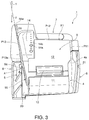
- FIG. 3 is an oblique view of the check processing device from the top front side.
- the case 1a of the check processing device 1 includes a rectangular bottom case part 2 of a specific thickness, and a top case part 3 disposed thereabove.
- Reading magnetic ink character data from the check S1, printing an endorsement on the check S1, and imaging both sides of the check S1, are performed in this order while the check S1 is conveyed through the check conveyance path P1. Note that when the check processing device 1 is placed in the normal upright operating position on a flat level surface as shown in FIG.
- the side of the check processing device 1 (case 1a) facing the user is referred to below as the front, the opposite side as the back, the direction between this front and back is the longitudinal axis Y, the direction parallel to the level surface and perpendicular to the longitudinal axis Y is the transverse axis X, and the direction perpendicular to the level surface is the vertical axis Z.
- the check path from the entry pocket 4 through the check conveyance path P1 to the exit pocket 5 is a vertical channel of a specific width that is formed in the top case part 3 and open at the top on the vertical axis Z.
- a check S1 is inserted to the entry pocket 4 standing on edge with the long sides at top and bottom, and is conveyed through the check conveyance path P1 and discharged into the exit pocket 5 in this same posture.
- the check conveyance path is a substantially U-shaped path that opens to the front when seen in plan view.
- the entry pocket 4 extends from the front toward the back of the top case part 3 on the right side of the transverse axis X, and the upstream path P11 portion of the check conveyance path P1 extends straight toward the back of the device from the check insertion opening 4a formed at the back end of the entry pocket 4.
- the downstream part of the upstream path portion P11 curves to the inside on the transverse axis X and joins the back path P12 portion of the check conveyance path P1.
- the back path P12 extends substantially straight on the transverse axis X, and the downstream end part thereof curves toward the front of the device and joins the downstream path P13 portion of the check conveyance path P1.
- the downstream path P13 is a straight path that is slanted at an acute angle ⁇ to the inside of the device width relative to the longitudinal axis Y, and in this embodiment of the invention continues at an angle of approximately 10 to 20 degrees.
- the downstream end of the downstream path P13 connects through a check discharge opening 5a to the exit pocket 5.
- the exit pocket 5 continues to the front of the device on the longitudinal axis Y.
- the top case part 3 is divided by this U-shaped check conveyance path into a right case member 6, rear case member 7, left case member 8, and an inside case member 9 located thereinside.
- a front cover 11, a back cover 12, a receipt exit 13 for the receipt printer described below, and an operating panel 14 are disposed to the top of the inside case member 9.
- a card insertion path 15 for inserting a card C to be read by the card scanner described below is also provided.
- the front cover 11 can open to the front pivoting on a position at the device front
- the back cover 12 can open to the back pivoting on a position at the device back.
- the receipt exit 13 is formed between the distal end of the front cover 11 and the distal end of the back cover 12, and has a narrow rectangular shape extending widthwise to the device.
- the operating panel 14 is formed at a place at the back side of the device on the left side of the back cover 12, is a substantially flat surface formed at a slightly higher position, and has a plurality of operating switches 14a and a display unit 14b with a plurality of LEDs for indicating the operating status.
- a roll paper compartment 16 is formed inside the inside case member 9 in the area covered by the back cover 12.
- the roll paper compartment 16 is open to the top and roll paper R (see FIG. 5 ) can be loaded or replaced.
- An automatic cutter 17 for cutting widthwise across the continuous paper S2 (see FIG. 5 ) delivered from the roll paper R stored in the roll paper compartment 16 is disposed inside the inside case member 9 in the area covered by the front cover 11.
- Information corresponding to check information for example, is printed on the continuous paper S2 conveyed from the roll paper R stored in the roll paper compartment 16, and the trailing end of the printed portion is cut to issue a receipt of a specific length from the receipt exit 13.
- An ink cartridge compartment 18 is located on the device front side of the automatic cutter 17, and an ink cartridge 19, which is the ink supply source for printing checks, is installed therein.
- an ink cartridge 19 which is the ink supply source for printing checks.
- the card insertion path 15 is formed in the flat top part 20 on the left side of the front cover 11 in the top of the inside case member 9.
- This top part 20 is at a lower position than the operating panel 14 at the back.
- the card insertion path 15 is a straight channel of a specific width and a specific depth that is open to the top in this top part 20.
- the rear end of the card insertion path 15 at the back of the device is connected to the top of the downstream end entrance P13a to the downstream path P13 portion of the check conveyance path P1, and the front end of the card insertion path 15 at the device front side is located near the side of the front cover 11.
- the card insertion path 15 is a straight insertion path extending along an extension of the downstream path P13, which is a straight conveyance path, toward the device front. More specifically, the card insertion path 15 extends to the inside of the device in the direction at the slanted angle ⁇ with respect to the longitudinal axis Y.
- the card C is inserted to the card insertion path 15 from the device front and pushed to the back as indicated in FIG. 3 .
- the card C pushed into the card insertion path 15 is conveyed from the card insertion path 15 to the downstream path P13, and is imaged by the optical reader 43 (see FIG. 4 ) described below for scanning checks that is disposed to the downstream path P13.
- the optical reader 43 see FIG. 4
- the card C is conveyed from the downstream path P13 to the card insertion path 15 at the device front.
- a card slot 21 for reading magnetic information from cards C that do not bend easily is also formed in the check processing device 1 according to this embodiment of the invention.
- This card slot 21 is formed in the top part of the right case member 6 of the top case part 3.
- a magnetic reader not shown is disposed inside this right case member 6, and magnetic information stored on the card C is read by pulling the card C from the rear end of the card slot 21 through the card slot 21 to the device front.
- FIG. 4 shows main parts of the check conveyance mechanism for conveying a check S1 through the U-shaped check conveyance path.
- the check conveyance mechanism is described below with reference to this figure.
- a paper feed roller 30a is disposed to the side on the right case member 6 side of the entry pocket 4, and a pressure member 30b is disposed to the side on the inside case member 9 side.
- the pressure member 30b pushes a check S1 inserted to the entry pocket 4 to the paper feed roller 30a side.
- the check S1 is fed into the upstream path P11 of the check conveyance path P1 by the paper feed roller 30a, which is driven by an in-feed motor 22.
- the check S1 is inserted standing on edge to the entry pocket 4 with the back of the check facing the inside of the device (the inside case member 9 side).
- the feed roller 31a is driven by the in-feed motor 22, and turns synchronously to the paper feed roller 30a.
- the retard roller 31b is urged to the feed roller 31a side, and separates and feeds the checks S1 one at a time downstream.
- a plurality of conveyance roller pairs 32 to 36 are disposed to the conveyance path parts of the check conveyance path P1 downstream from the feed roller 31a.
- Conveyance roller pair 32 is disposed to the upstream path P11
- conveyance roller pairs 33 and 34 are disposed to the back path P12
- the remaining conveyance roller pairs 35 and 36 are disposed to the downstream path P13.
- Each of the conveyance roller pairs 32 to 36 has a drive roller 32a, 33a, 34a, 35a, 36a on the inside case member 9 side, and a follower roller 32b, 33b, 34b, 35b, 36b on the outside right case member 6, rear case member 7, or left case member 8 side opposite the corresponding drive roller with the check conveyance path P1 therebetween.
- the drive rollers 32a, 33a, 34a, 35a, 36a are synchronously driven rotationally by a drive motor 40 through an endless belt 37.
- the follower rollers 32b, 33b, 34b, 35b, 36b are urged by an urging member not shown to the corresponding drive roller 32a - 36a side.
- a magnetic reading unit 41 is also disposed to the upstream path P11 of the check conveyance path P1.
- the magnetic reading unit 41 has a magnetic scanner 41a such as an MICR unit that can read magnetic information recorded in magnetic ink, for example, on the check S1, and the magnetic scanner 41a is disposed to the right case member 6 with the magnetic reading surface facing the upstream path P11.
- a pressure roller 41b is disposed opposite the magnetic reading surface of the magnetic scanner 41a with the upstream path P11 therebetween. The conveyed check S1 is pressed to the magnetic reading surface of the magnetic scanner 41a by the pressure roller 41b, and the magnetic information is reliably read by the magnetic scanner 41a.
- a check print unit 42 that prints an endorsement on the back of the check S1 is disposed to the back path P12, which extends continuously from the downstream end of the upstream path P11 widthwise to the device, in an area on the left corner side of the device.
- the check print unit 42 has an inkjet line head 42a disposed extending vertically to the device with the nozzle surface of the inkjet line head 42a facing the back path P12.
- a platen 42b that defines the printing position of the inkjet line head 42a is disposed to a place on the rear case member 7 facing the nozzle surface with the back path P12 therebetween.
- the ink supply source of the inkjet line head 42a is the ink cartridge 19 loaded in the ink cartridge compartment 18. Note that a thermal head could be used instead of an inkjet head 42a. Using a line head as in this embodiment is desirable because the check print unit 42 can be made more compact than when a serial head is used.
- the conveyance roller pairs 35 and 36 are disposed to the downstream path P13 of the check conveyance path P1, and the optical reader 43 for imaging both sides of the check S1 is disposed to the portion of the conveyance path between these roller pairs.
- the optical reader 43 has an optical scanner 43a for imaging the front of the check S1 and an optical scanner 43b for imaging the back disposed with the scanning surfaces thereof facing each other with the downstream path P13 therebetween.
- the downstream end of the downstream path P13 is connected to the check discharge opening 5a that discharges the processed check S1 after reading magnetic information, printing an endorsement, and imaging are completed into the exit pocket 5.
- the exit pocket 5 is open at the top, and a check S1 deposited into the exit pocket 5 can be removed from above. Because both the entry pocket 4 and exit pocket 5 are open at the top, the operator can always handle the check S1 from above the front of the check processing device 1.
- FIG. 5 is a vertical section view of the check processing device 1.
- the receipt printing mechanism assembled in the inside case member 9 of the top case part 3 is described next primarily with reference to this figure.
- the receipt printing mechanism includes the roll paper compartment 16 that holds the roll paper R described above.
- the roll paper compartment 16 holds the roll paper R so that the roll can rotate freely horizontally widthwise to the device.
- the continuous paper path P2 that guides the continuous paper S2 pulled from the roll paper R to the receipt exit 13 extends from the roll paper compartment 16 to the device front with the width of the paper path aligned with the device width.
- the bottom of the roll paper compartment 16 is defined by a curved concave bottom panel 51, and the top opening is covered by the back cover 12.
- the back end of the back cover 12 is supported by a hinge 52 of which the center axis is the pivot axis extending transversely, and the back cover 12 opens and closes pivoting on this hinge 52.
- the continuous paper S2 pulled from the roll paper R in the roll paper compartment 16 is guided by a paper guide 53, which is attached to the front edge part of the bottom panel 51, to the continuous paper print unit 54.
- a guide roller that rotates freely to reduce the rolling resistance to the roll paper R may be disposed to the bottom of the roll paper compartment 16, and the roll paper R placed thereon.
- the continuous paper print unit 54 includes a thermal line head 54a and a platen roller 54b that conveys while pressing the continuous paper S2 to the printhead surface of the thermal head 54a.
- the thermal line head 54a is disposed to the inside case member 9 side, and the platen roller 54b is mounted at a position on the distal end side of the back cover 12.
- the automatic cutter 17 is disposed above the continuous paper print unit 54.
- the automatic cutter 17 includes a fixed knife 17a, and a drive unit 17c including a movable knife 17b.
- the fixed knife 17a is disposed on the back cover 12 side, and the movable knife 17b and drive unit 17c are disposed on the inside case member 9 side.
- the continuous paper S2 passes the cutting position of the automatic cutter 17 after passing the printing position of the continuous paper print unit 54, and is discharged to the top from the receipt exit 13 open above the automatic cutter 17.
- a cutter 55 (see FIG. 1 to FIG. 3 ) is provided widthwise to the device along the front edge of the receipt exit 13, enabling the operator to cut the continuous paper S2 at a desirable position.
- the check processing device 1 has a card scanner mechanism for imaging the card C inserted from the card insertion path 15.
- the card scanner mechanism includes the card insertion path 15, and a card sensor 57 that detects a card C inserted from the card insertion path 15.
- the card sensor 57 could be a photocoupler or other optical sensor, or a mechanical switch, for example.
- the conveyance roller pairs 35, 36 of the check processing mechanism disposed to the downstream path P13 turn, and a card in-feed operation that conveys the card C inserted from the card insertion path 15 along the downstream path P13 toward the device back, and a card out-feed operation that conveys and returns the in-fed card C to the device front into the card insertion path 15, are performed.
- a card scanning operation that images the card C conveyed from the downstream path P13 to the card insertion path 15 using the optical reader 43 used for check imaging is also performed.
- the discharge direction of the check S1 that is recovered into the exit pocket 5 from the straight downstream path P13 through which the check S1 is conveyed is aligned with the longitudinal axis Y or a direction at an acute angle relative to the longitudinal axis Y toward the outside of the device width.
- the discharged checks S1 are collected in the exit pocket 5 aligned in the direction of the longitudinal axis Y and stacked sequentially widthwise to the device.
- the direction of the card insertion path 15 continues in line with an extension of the downstream path P13, and is a direction at an acute angle ⁇ to the inside towards the front of the device relative to the longitudinal axis Y.
- a card C can therefore be inserted from the card insertion path 15 to the downstream end entrance P13a of the downstream path P13 and scanned without interference from the checks S1 even when checks S1 are stacked aligned with the longitudinal axis Y in the exit pocket 5.
- the card insertion path 15 can be located beside the exit pocket 5 at the device front, and cards C can be handled in the same way as checks S1 by looking directly at the card insertion path 15 from the device front. Card C scanning is therefore easier and handling cards C can be improved.
- the exit pocket 5 is a recessed pocket that extends in the direction of the longitudinal axis Y, and the card insertion path 15 is disposed to the inside of the device from the exit pocket 5.
- the card insertion path 15 can therefore be provided without increasing device width. Note that if there is sufficient room in the device width, the card insertion path 15 could be provided extending at an acute angle to the outside on the outside of the exit pocket 5 extending on the longitudinal axis Y.
- a straight extension path 58 extends from the upstream end of the downstream path P13, that is, from the junction with the downstream end of the back path P12, in line with an extension of the downstream path P13 towards the device back.
- the back end 58a of this extension path 58 is open at the back of the device.
- the length of the downstream path P13 alone may not be sufficient for operations that convey all of the card C past the reading position of the optical reader 43 (specifically, the operation that scans the entire surface of the card C in the conveyance direction).
- This embodiment enables such operations, however, by forming the extension path 58 with the back end 58a thereof open at the back.
- This embodiment also forms the card insertion path 15 in the top part 20 at a height in the middle of the depth of the downstream path P13. More specifically, the bottom of the card insertion path 15 is located at a height between the bottom and the open top of the downstream path P13 channel.
- the width of driver license cards and other personal identification cards is generally smaller than the width of most common checks S1. Because the height of the downstream path P13 corresponds to the check S1 width, the elevation of the card insertion path 15 can be disposed to a higher position if the upper part of this downstream path P13 is used as the conveyance path for scanning cards, and a card C can be inserted more easily than when the card C is inserted to the lower part of the check conveyance path P1 below the top part 20.
- Operation of the check processing device 1 is controlled by a MPU or other control unit 61.
- the control unit 61 is mounted on a circuit board 60 disposed to the top of the bottom case part 2. Maintenance is improved by updating a driver, for example, by controlling the check processing mechanism, receipt printing mechanism, and card scanning mechanism of the check processing device 1 with a single control unit 61.
- the control unit 61 may be provided as a control circuit board disposed to the back side of the circuit board 60 (the opposite side as the side on which the check conveyance path P1 is formed) instead of on the top of the circuit board 60 as shown in FIG. 4 .
- control unit 61 controls driving the in-feed motor 22 of the check processing mechanism and feeds the check S1 into the check conveyance path P1 by means of the paper feed roller 30a. Synchronized to this, the control unit 61 controls driving the drive motor 40 and conveys checks S1 one by one through the upstream path P11 by means of the feed roller 31a and retard roller 31b.
- the control unit 61 first controls the magnetic reading unit 41 to read the magnetic information from the check S1, and captures the magnetic information that was read. Next, the control unit 61 prints an endorsement on the back of the check S1 with the check print unit 42 based on the read magnetic information. The control unit 61 then controls the optical reader 43 to image both sides of the check S1, and captures the scanned image information. The imaged check S1 is then discharged by the conveyance roller pair 36 into the exit pocket 5.
- the user's workload can be reduced because reading magnetic information, printing an endorsement, and imaging can be done in a single continuous process by the check processing mechanism of the check processing device 1.
- the control unit 61 also controls the in-feed motor 22 of the receipt printing mechanism to rotationally drive the platen roller 54b and convey the continuous paper S2 from the roll paper R through the continuous paper path P2. While the continuous paper S2 is conveyed between the thermal line head 54a and platen roller 54b, necessary information is printed on the continuous paper S2 as controlled by the control unit 61. The printed continuous paper S2 is then discharged to the outside from the receipt exit 13 by the platen roller 54b. When the printed leading end of the continuous paper S2 has been discharged and the trailing end of the printed portion reaches the cutting position of the automatic cutter 17, continuous paper S2 conveyance stops, the automatic cutter 17 is driven by the control unit 61 to cut widthwise, and the printed portion of the continuous paper S2 is cut off. The printed sheet that is cut to a specific length is then issued as a receipt.
- control unit 61 When the control unit 61 detects based on output from the card sensor 57 that a card C was inserted to the card insertion path 15, it controls driving the drive motor 40 of the check conveyance mechanism and drives the conveyance roller pairs 35, 36 for check conveyance to perform the card in-feed operation that conveys the card C inserted to the card insertion path 15 into the downstream path P13.
- the length of the card C in the conveyance direction is detected during the card in-feed operation based on the output from the card sensor 57.
- the card in-feed operation stops when the trailing end in the in-feed direction of the card C has passed the reading position of the optical reader 43, the conveyance roller pairs 35, 36 are then driven in reverse, and the card out-feed operation that discharges the card C starts.
- the optical reader 43 is driven during the card out-feed operation to perform the scanning operation that images the front and back sides of the card C passing the scanning position.
- the card out-feed operation stops after the card C is fed a specific distance after the trailing end in the out-feed direction of the card C is detected by the card sensor 57. Images of the card C are thus captured.
- a configuration in which the magnetic information and image information are passed to the control unit 61 is described in this embodiment, but the captured information could be output to an external device such as a computer or display.
- output from the external device could be input to the control unit 61, and the control unit 61 could print using the check print unit 42 and continuous paper print unit 54 based on commands from the external device.
- the check discharge direction A in which checks S1 are discharged into the exit pocket 5 and the recovery direction in which checks S1 are recovered into the exit pocket 5 from the check conveyance path P1 that conveys checks S1 that bend easily are different from the insertion direction of the card insertion path 15 to which cards C are inserted for imaging cards C that do not bend easily.
- Cards C can therefore be inserted from the card insertion path 15 to the downstream path P13 of the check conveyance path P1 and the cards C can be imaged without interference from a check S1 even when a check S1 has been recovered in the exit pocket 5.
- the card insertion path 15 can be located adjacent to the exit pocket 5 located at the device side, and cards C can be handled in the same way as checks S1 are handled from the device front while looking directly at the card insertion path 15. The ease of scanning cards C and card C handling can therefore be improved.
- each part of the check processing device 1 can be operated from the device front as will be understood from FIG. 1 to FIG. 3 . Operability is therefore better, and operations such as replacing roll paper and replacing the ink cartridge can be performed more easily than when parts must be operated from the side or back and the operator must reach around to the side or back of the device.
- check conveyance path P1 and continuous paper path P2 are separated in this check processing device 1, the check S1 conveyed through the check conveyance path P1 and the continuous paper S2 conveyed through the continuous paper path P2 can be conveyed independently. In addition, checks S1 and continuous paper S2 will not contact each other even if conveyed simultaneously, and paper jams do therefore not occur. Yet further, because the check print unit 42 that prints on checks S1, and the continuous paper print unit 54 that prints on continuous paper S2, are at separate locations and print independently, checks S1 and continuous paper S2 can be printed simultaneously or with a specific time gap therebetween irrespective of the printing status of the other.
- the continuous paper path P2 is a conveyance path that extends in the part enclosed by the U-shaped check conveyance path P1 to the device front on the open side of the U.
- a continuous paper path P2 of the required length can therefore be assured without interfering with the check conveyance path P1, and the parts of the receipt printing mechanism can be arranged more efficiently in the space surrounded by the U-shaped check conveyance path P1 than when the continuous paper path P2 extends in the device width direction.
- a check processing device 1 with a receipt printing mechanism that is small and compact overall can therefore be achieved.
- the card insertion path 15 for card scanning is located at a position beside the inside side of the exit pocket 5.
- the card insertion path 15 can be located on the outside of the exit pocket 5 in the device width direction.
- the card insertion path 15 can be located on the entry pocket 4 side on the inside in the device width direction.
- the card insertion path 15 is preferably located on the entry pocket 4 side.
- the upstream path P11 of the check conveyance path P1 is a straight path, and the optical reader 43 for scanning checks, or a dedicated optical reader 43 for scanning cards, is located in this area.
- the card insertion path 15 can be located on the outside of the entry pocket 4 in the device width direction.
Landscapes
- Engineering & Computer Science (AREA)
- Multimedia (AREA)
- Signal Processing (AREA)
- Physics & Mathematics (AREA)
- General Physics & Mathematics (AREA)
- Theoretical Computer Science (AREA)
- Mechanical Engineering (AREA)
- Computer Vision & Pattern Recognition (AREA)
- Artificial Intelligence (AREA)
- Facsimiles In General (AREA)
- Inspection Of Paper Currency And Valuable Securities (AREA)
- Facsimile Scanning Arrangements (AREA)
- Devices For Checking Fares Or Tickets At Control Points (AREA)
- Conveying Record Carriers (AREA)
- Image Input (AREA)
- Feeding Of Articles By Means Other Than Belts Or Rollers (AREA)
Abstract
Description
- The present invention relates to a media processing device such as a check processing device having an optical reading unit that reads an image of a medium conveyed through a curved conveyance path. The invention relates more specifically to a media processing device that is extremely easy to operate and can scan images from both first media such as checks that bend easily, and second media such as driver licenses and other cards that do not bend easily.
- Checks are commonly used in bank operations for settling deposit and withdrawal processes. When a check is used to settle a transaction, the date and signature on the check are confirmed at the teller window, the necessary deposit or withdrawal process is completed, and the check used in the transaction is then endorsed on the back. A receipt related to the check process is then given to the customer. A driver license or other type of identification card is typically required to confirm the identity of the person presenting the check in each transaction, and a copy of the identification card may be taken and stored as needed. These processes must be frequently performed in a short time at the teller window.
- These processes are increasingly performed electronically. More specifically, magnetic information and optical information is captured from the checks using magnetic ink character readers (MICR) and optical scanners, and checks are endorsed with a printer.
- Japanese Unexamined Patent Appl. Pub.
JP-A-2004-243764 - Japanese Unexamined Patent Appl. Pub.
JP-A-2004-297761 JP-A-2004-297761 - In check processing devices with a U-shaped check conveyance path the check conveyance path is formed from the front of the device, curves at the back of the device, and then returns to the front again, enabling the operator to insert the check to be processed and retrieve the check after processing is completed from the front. However, while checks can be easily handled from the front using the data reading device disclosed in
JP-A-2004-297761 - More specifically, in the data reading device described in
JP-A-2004-297761 - A media processing device according to the invention enables scanning cards and other second media that do not bend easily from the front of the device with the same ease of use as processing checks and other first media that bend easily.
- A media processing device according to the invention has a device case with a media entrance and a media exit; a media conveyance path formed in the device case to guide first media inserted from the media entrance from the front to the back on a front-back axis, and then from the back to the front on the front-back axis to the media exit, where when the device case is placed upright on a flat surface one direction parallel to the surface is the front-back axis, the direction parallel to the surface and perpendicular to the front-back axis is a device width axis, and the direction perpendicular to the surface is a vertical axis; a straight conveyance path connected to the media conveyance path at the media entrance or the media exit; a straight second media insertion path that extends from the media entrance or the media exit on a line extending the straight conveyance path toward the front on the front-back axis, and is formed in a top part of the device case facing up on the vertical axis, for inserting second media from the media entrance to the straight conveyance path or discharging second media to the outside of the straight conveyance path from the media exit; and an optical reading unit that images media passing through the straight conveyance path. The straight conveyance path and the second media insertion path extend in a direction on the front-back axis or a direction slanted at an acute angle with respect to the front-back axis; and the insertion direction of the first media inserted from the media entrance or the discharge direction of the first media discharged from the media exit is a direction different from the direction of the second media insertion path, and is a direction on the front-back axis or a direction slanted at an acute angle with respect to the front-back axis.
- The direction of the second insertion path to which second media such as cards that do not bend easily are inserted is a direction slanted an acute angle to the insertion direction of first media inserted from the media entrance or the discharge direction of first media discharged from the media exit of the media conveyance path that conveys first media such as checks that bend easily. Second media can therefore be inserted to the media conveyance path from the second insertion path formed in the top of the media processing device, and the second media can be imaged using the image reading unit disposed to the straight conveyance path, without interfering with first media inserted to the media conveyance path or first media discharged from the media conveyance path. As a result, the second media insertion path can be disposed to a position adjacent to the media entrance or the media exit of the media conveyance path. Second media can therefore be handled in the same way as first media are handled from the device front while looking directly at the second media insertion path, and the ease of scanning second media or handling second media can be improved.
- In order to suppress increasing device dimensions and make the device small and compact, and particularly to suppress increasing the device width, the insertion direction of the first media inserted from the media entrance or the discharge direction of the first media discharged from the media exit preferably is a direction in parallel with the front-back axis; and/or the direction of the straight conveyance path and the second media insertion path preferably is slanted toward the front on the front-back axis at an acute angle to the inside on the device width axis with respect to the direction on the front-back axis.
- Preferably, the media conveyance path has a conveyance path portion that curves and extends in the direction of the device width axis from the end of the straight conveyance path at the back side on the front-back axis. In order to assure sufficient length in the conveyance path for conveying the second media past the reading position of the image reading unit when the straight conveyance path portion of the media conveyance path is short or the length of the second media in the conveyance direction is long, an extension path that preferably extends straight along a linear extension of the straight conveyance path is preferably formed from the back end of the straight conveyance path on the front-back axis, and the end of the extension path at the back on the front-back axis is preferably open to the device back. Preferably, the extension path extends in parallel with the straight conveyance path.
- When the straight conveyance path is a conveyance path connected to the media exit of the media conveyance path, and has an exit pocket that recovers first media discharged from the media exit, the second media insertion path is preferably disposed to the inside (or the outside) of the exit pocket on the device width axis, the exit pocket preferably extends in the direction of the front-back axis, and the direction of the straight conveyance path and the second media insertion path is slanted toward the front on the front-back axis at an acute angle to the inside (or outside) on the device width axis with respect to the direction of the front-back axis.
- When checks are used as the first media, for example, the cards or other second media are smaller in width than the first media. When the bottom of the straight conveyance path of the media conveyance path is determined by a channel of a specific depth that is preferably open at the top on the vertical axis, and the exit pocket is preferably a recessed part that is open at the device top and preferably has a bottom at the same height as the channel bottom of the straight conveyance path, the second insertion path is preferably disposed at a height in the middle of the straight conveyance path in the channel depth direction. More specifically, the bottom of the second media insertion path is preferably at a height between the channel bottom of the straight conveyance path and the channel top opening that is open to the top on the vertical axis, and the second media inserted from the second media insertion path to the straight conveyance path is preferably conveyed through the straight conveyance path at the same height as the bottom of the second media insertion path. This enables disposing the second media insertion path at a position higher than the bottom of the straight conveyance path, and makes inserting second media with a narrow width easier than inserting them from the device top to the bottom of the straight conveyance path channel.
- The media processing device according to the invention can be used as a check processing device. In this case, the configuration described above is preferably complemented by a magnetic reading unit that reads magnetic information from first media conveyed through the media conveyance path, and a media print unit that prints on first media conveyed through the media conveyance path, the media conveyance path is a check conveyance path, and the second media insertion path is formed as a card insertion path.
- Other objects and attainments together with a fuller understanding of the invention will become apparent and appreciated by referring to the following description and claims taken in conjunction with the accompanying drawings.
-
-
FIG. 1 is an exemplary oblique view showing a check processing device according to the invention. -
FIG. 2 is an exemplary oblique view of the check processing device shown inFIG. 1 with the two top covers open. -
FIG. 3 is an exemplary oblique view of the check processing device shown inFIG. 1 when seen from above. -
FIG. 4 exemplarily shows the configuration of the check conveyance mechanism in the check processing device shown inFIG. 1 . -
FIG. 5 is an exemplary vertical section view showing the receipt printing mechanism in the check processing device shown inFIG. 1 . -
FIG. 6 exemplarily shows examples of card insertion paths. - A preferred embodiment of a media processing device according to the present invention is described below with reference to the accompanying figures. The media processing device according to this embodiment of the invention is exemplarily rendered by a check processing device that processes checks, which are an exemplary type of first media that bends easily. This check processing device has a card scanning mechanism for imaging driver licenses and similar cards, which are an exemplary type of second media that does not bend easily, for customer verification when processing checks, and a receipt printing mechanism for issuing receipts on which processed check information, for example, is printed. It will also be obvious that the invention can be similarly applied to media processing devices for processing first media that bend easily other than checks. The invention can also be applied to media processing devices that do not have a receipt printing mechanism.
-
FIG. 1 is an oblique view of a check processing device according to a preferred embodiment of the invention from diagonally above the front right side.FIG. 2 is an oblique view of the check processing device from diagonally above the front left side with the front and back covers disposed to the top open.FIG. 3 is an oblique view of the check processing device from the top front side. - Referring to these figures, the
case 1a of thecheck processing device 1 includes a rectangularbottom case part 2 of a specific thickness, and atop case part 3 disposed thereabove. Anentry pocket 4 to which a check S1 to be processed is inserted, a check conveyance path P1 through which the check S1 fed from theentry pocket 4 is conveyed, and anexit pocket 5 for recovering the check S1 delivered from the check conveyance path P1, are formed in thetop case part 3. Reading magnetic ink character data from the check S1, printing an endorsement on the check S1, and imaging both sides of the check S1, are performed in this order while the check S1 is conveyed through the check conveyance path P1. Note that when thecheck processing device 1 is placed in the normal upright operating position on a flat level surface as shown inFIG. 1 , the side of the check processing device 1 (case 1a) facing the user is referred to below as the front, the opposite side as the back, the direction between this front and back is the longitudinal axis Y, the direction parallel to the level surface and perpendicular to the longitudinal axis Y is the transverse axis X, and the direction perpendicular to the level surface is the vertical axis Z. - The check path from the
entry pocket 4 through the check conveyance path P1 to theexit pocket 5 is a vertical channel of a specific width that is formed in thetop case part 3 and open at the top on the vertical axis Z. As shown inFIG. 1 , a check S1 is inserted to theentry pocket 4 standing on edge with the long sides at top and bottom, and is conveyed through the check conveyance path P1 and discharged into theexit pocket 5 in this same posture. The check conveyance path is a substantially U-shaped path that opens to the front when seen in plan view. - More specifically, as will be understood from
FIG. 3 , theentry pocket 4 extends from the front toward the back of thetop case part 3 on the right side of the transverse axis X, and the upstream path P11 portion of the check conveyance path P1 extends straight toward the back of the device from thecheck insertion opening 4a formed at the back end of theentry pocket 4. The downstream part of the upstream path portion P11 curves to the inside on the transverse axis X and joins the back path P12 portion of the check conveyance path P1. The back path P12 extends substantially straight on the transverse axis X, and the downstream end part thereof curves toward the front of the device and joins the downstream path P13 portion of the check conveyance path P1. The downstream path P13 is a straight path that is slanted at an acute angle θto the inside of the device width relative to the longitudinal axis Y, and in this embodiment of the invention continues at an angle of approximately 10 to 20 degrees. The downstream end of the downstream path P13 connects through a check discharge opening 5a to theexit pocket 5. Theexit pocket 5 continues to the front of the device on the longitudinal axis Y. - The
top case part 3 is divided by this U-shaped check conveyance path into aright case member 6,rear case member 7, leftcase member 8, and aninside case member 9 located thereinside. Afront cover 11, aback cover 12, areceipt exit 13 for the receipt printer described below, and anoperating panel 14 are disposed to the top of theinside case member 9. Acard insertion path 15 for inserting a card C to be read by the card scanner described below is also provided. - As will be understood from
FIG. 2 , thefront cover 11 can open to the front pivoting on a position at the device front, and theback cover 12 can open to the back pivoting on a position at the device back. Thereceipt exit 13 is formed between the distal end of thefront cover 11 and the distal end of theback cover 12, and has a narrow rectangular shape extending widthwise to the device. The operatingpanel 14 is formed at a place at the back side of the device on the left side of theback cover 12, is a substantially flat surface formed at a slightly higher position, and has a plurality ofoperating switches 14a and adisplay unit 14b with a plurality of LEDs for indicating the operating status. - A
roll paper compartment 16 is formed inside theinside case member 9 in the area covered by theback cover 12. When theback cover 12 opens, theroll paper compartment 16 is open to the top and roll paper R (seeFIG. 5 ) can be loaded or replaced. Anautomatic cutter 17 for cutting widthwise across the continuous paper S2 (seeFIG. 5 ) delivered from the roll paper R stored in theroll paper compartment 16 is disposed inside theinside case member 9 in the area covered by thefront cover 11. Information corresponding to check information, for example, is printed on the continuous paper S2 conveyed from the roll paper R stored in theroll paper compartment 16, and the trailing end of the printed portion is cut to issue a receipt of a specific length from thereceipt exit 13. Anink cartridge compartment 18 is located on the device front side of theautomatic cutter 17, and anink cartridge 19, which is the ink supply source for printing checks, is installed therein. When thefront cover 11 opens, thedrive unit 17c of theautomatic cutter 17 is exposed and theink cartridge compartment 18 is open to the top, thus enabling inspecting theautomatic cutter 17 and replacing the ink cartridge easily from the top of the device. - As will be understood from
FIG. 2 andFIG. 3 , thecard insertion path 15 is formed in the flattop part 20 on the left side of thefront cover 11 in the top of theinside case member 9. Thistop part 20 is at a lower position than the operatingpanel 14 at the back. Thecard insertion path 15 is a straight channel of a specific width and a specific depth that is open to the top in thistop part 20. The rear end of thecard insertion path 15 at the back of the device is connected to the top of the downstream end entrance P13a to the downstream path P13 portion of the check conveyance path P1, and the front end of thecard insertion path 15 at the device front side is located near the side of thefront cover 11. As will be understood fromFIG. 3 , thecard insertion path 15 is a straight insertion path extending along an extension of the downstream path P13, which is a straight conveyance path, toward the device front. More specifically, thecard insertion path 15 extends to the inside of the device in the direction at the slanted angle θ with respect to the longitudinal axis Y. - To scan an image of a card C that does not bend easily, the card C is inserted to the
card insertion path 15 from the device front and pushed to the back as indicated inFIG. 3 . The card C pushed into thecard insertion path 15 is conveyed from thecard insertion path 15 to the downstream path P13, and is imaged by the optical reader 43 (seeFIG. 4 ) described below for scanning checks that is disposed to the downstream path P13. After scanning, the card C is conveyed from the downstream path P13 to thecard insertion path 15 at the device front. - A
card slot 21 for reading magnetic information from cards C that do not bend easily is also formed in thecheck processing device 1 according to this embodiment of the invention. Thiscard slot 21 is formed in the top part of theright case member 6 of thetop case part 3. A magnetic reader not shown is disposed inside thisright case member 6, and magnetic information stored on the card C is read by pulling the card C from the rear end of thecard slot 21 through thecard slot 21 to the device front. -
FIG. 4 shows main parts of the check conveyance mechanism for conveying a check S1 through the U-shaped check conveyance path. The check conveyance mechanism is described below with reference to this figure. - A
paper feed roller 30a is disposed to the side on theright case member 6 side of theentry pocket 4, and apressure member 30b is disposed to the side on theinside case member 9 side. Thepressure member 30b pushes a check S1 inserted to theentry pocket 4 to thepaper feed roller 30a side. The check S1 is fed into the upstream path P11 of the check conveyance path P1 by thepaper feed roller 30a, which is driven by an in-feed motor 22. In this embodiment the check S1 is inserted standing on edge to theentry pocket 4 with the back of the check facing the inside of the device (theinside case member 9 side). - A
feed roller 31a that feeds the check S1 supplied from theentry pocket 4, and aretard roller 31b that faces thefeed roller 31a with the upstream path P11 therebetween, are disposed to the upstream path P11 of the check conveyance path P1. Thefeed roller 31a is driven by the in-feed motor 22, and turns synchronously to thepaper feed roller 30a. Theretard roller 31b is urged to thefeed roller 31a side, and separates and feeds the checks S1 one at a time downstream. - A plurality of conveyance roller pairs 32 to 36 are disposed to the conveyance path parts of the check conveyance path P1 downstream from the
feed roller 31a.Conveyance roller pair 32 is disposed to the upstream path P11, conveyance roller pairs 33 and 34 are disposed to the back path P12, and the remaining conveyance roller pairs 35 and 36 are disposed to the downstream path P13. Each of the conveyance roller pairs 32 to 36 has adrive roller inside case member 9 side, and afollower roller right case member 6,rear case member 7, or leftcase member 8 side opposite the corresponding drive roller with the check conveyance path P1 therebetween. Thedrive rollers drive motor 40 through anendless belt 37. Thefollower rollers corresponding drive roller 32a - 36a side. - A
magnetic reading unit 41 is also disposed to the upstream path P11 of the check conveyance path P1. Themagnetic reading unit 41 has amagnetic scanner 41a such as an MICR unit that can read magnetic information recorded in magnetic ink, for example, on the check S1, and themagnetic scanner 41a is disposed to theright case member 6 with the magnetic reading surface facing the upstream path P11. Apressure roller 41b is disposed opposite the magnetic reading surface of themagnetic scanner 41a with the upstream path P11 therebetween. The conveyed check S1 is pressed to the magnetic reading surface of themagnetic scanner 41a by thepressure roller 41b, and the magnetic information is reliably read by themagnetic scanner 41a. - A
check print unit 42 that prints an endorsement on the back of the check S1 is disposed to the back path P12, which extends continuously from the downstream end of the upstream path P11 widthwise to the device, in an area on the left corner side of the device. Thecheck print unit 42 has aninkjet line head 42a disposed extending vertically to the device with the nozzle surface of theinkjet line head 42a facing the back path P12. Aplaten 42b that defines the printing position of theinkjet line head 42a is disposed to a place on therear case member 7 facing the nozzle surface with the back path P12 therebetween. As described with reference toFIG. 2 , the ink supply source of theinkjet line head 42a is theink cartridge 19 loaded in theink cartridge compartment 18. Note that a thermal head could be used instead of aninkjet head 42a. Using a line head as in this embodiment is desirable because thecheck print unit 42 can be made more compact than when a serial head is used. - The conveyance roller pairs 35 and 36 are disposed to the downstream path P13 of the check conveyance path P1, and the
optical reader 43 for imaging both sides of the check S1 is disposed to the portion of the conveyance path between these roller pairs. Theoptical reader 43 has anoptical scanner 43a for imaging the front of the check S1 and anoptical scanner 43b for imaging the back disposed with the scanning surfaces thereof facing each other with the downstream path P13 therebetween. - The downstream end of the downstream path P13 is connected to the
check discharge opening 5a that discharges the processed check S1 after reading magnetic information, printing an endorsement, and imaging are completed into theexit pocket 5. Theexit pocket 5 is open at the top, and a check S1 deposited into theexit pocket 5 can be removed from above. Because both theentry pocket 4 andexit pocket 5 are open at the top, the operator can always handle the check S1 from above the front of thecheck processing device 1. -
FIG. 5 is a vertical section view of thecheck processing device 1. The receipt printing mechanism assembled in theinside case member 9 of thetop case part 3 is described next primarily with reference to this figure. The receipt printing mechanism includes theroll paper compartment 16 that holds the roll paper R described above. Theroll paper compartment 16 holds the roll paper R so that the roll can rotate freely horizontally widthwise to the device. The continuous paper path P2 that guides the continuous paper S2 pulled from the roll paper R to thereceipt exit 13 extends from theroll paper compartment 16 to the device front with the width of the paper path aligned with the device width. - The bottom of the
roll paper compartment 16 is defined by a curved concavebottom panel 51, and the top opening is covered by theback cover 12. The back end of theback cover 12 is supported by ahinge 52 of which the center axis is the pivot axis extending transversely, and theback cover 12 opens and closes pivoting on thishinge 52. - The continuous paper S2 pulled from the roll paper R in the
roll paper compartment 16 is guided by apaper guide 53, which is attached to the front edge part of thebottom panel 51, to the continuouspaper print unit 54. A guide roller that rotates freely to reduce the rolling resistance to the roll paper R may be disposed to the bottom of theroll paper compartment 16, and the roll paper R placed thereon. - The continuous
paper print unit 54 includes athermal line head 54a and aplaten roller 54b that conveys while pressing the continuous paper S2 to the printhead surface of thethermal head 54a. In this embodiment thethermal line head 54a is disposed to theinside case member 9 side, and theplaten roller 54b is mounted at a position on the distal end side of theback cover 12. - The
automatic cutter 17 is disposed above the continuouspaper print unit 54. Theautomatic cutter 17 includes a fixedknife 17a, and adrive unit 17c including amovable knife 17b. The fixedknife 17a is disposed on theback cover 12 side, and themovable knife 17b and driveunit 17c are disposed on theinside case member 9 side. The continuous paper S2 passes the cutting position of theautomatic cutter 17 after passing the printing position of the continuouspaper print unit 54, and is discharged to the top from thereceipt exit 13 open above theautomatic cutter 17. Note that a cutter 55 (seeFIG. 1 to FIG. 3 ) is provided widthwise to the device along the front edge of thereceipt exit 13, enabling the operator to cut the continuous paper S2 at a desirable position. - In addition to a receipt printing mechanism, the
check processing device 1 has a card scanner mechanism for imaging the card C inserted from thecard insertion path 15. Referring toFIG. 4 , the card scanner mechanism includes thecard insertion path 15, and acard sensor 57 that detects a card C inserted from thecard insertion path 15. Thecard sensor 57 could be a photocoupler or other optical sensor, or a mechanical switch, for example. - When insertion of a card C to the
card insertion path 15 is detected by thecard sensor 57, the conveyance roller pairs 35, 36 of the check processing mechanism disposed to the downstream path P13 turn, and a card in-feed operation that conveys the card C inserted from thecard insertion path 15 along the downstream path P13 toward the device back, and a card out-feed operation that conveys and returns the in-fed card C to the device front into thecard insertion path 15, are performed. A card scanning operation that images the card C conveyed from the downstream path P13 to thecard insertion path 15 using theoptical reader 43 used for check imaging is also performed. - As will be understood from
FIG. 1 andFIG. 3 , the discharge direction of the check S1 that is recovered into theexit pocket 5 from the straight downstream path P13 through which the check S1 is conveyed, that is, the direction in which the check S1 is discharged through the check discharge opening 5a into theexit pocket 5, is aligned with the longitudinal axis Y or a direction at an acute angle relative to the longitudinal axis Y toward the outside of the device width. The discharged checks S1 are collected in theexit pocket 5 aligned in the direction of the longitudinal axis Y and stacked sequentially widthwise to the device. The direction of thecard insertion path 15, however, continues in line with an extension of the downstream path P13, and is a direction at an acute angle θ to the inside towards the front of the device relative to the longitudinal axis Y. - A card C can therefore be inserted from the
card insertion path 15 to the downstream end entrance P13a of the downstream path P13 and scanned without interference from the checks S1 even when checks S1 are stacked aligned with the longitudinal axis Y in theexit pocket 5. As a result, thecard insertion path 15 can be located beside theexit pocket 5 at the device front, and cards C can be handled in the same way as checks S1 by looking directly at thecard insertion path 15 from the device front. Card C scanning is therefore easier and handling cards C can be improved. - In addition, the
exit pocket 5 is a recessed pocket that extends in the direction of the longitudinal axis Y, and thecard insertion path 15 is disposed to the inside of the device from theexit pocket 5. Thecard insertion path 15 can therefore be provided without increasing device width. Note that if there is sufficient room in the device width, thecard insertion path 15 could be provided extending at an acute angle to the outside on the outside of theexit pocket 5 extending on the longitudinal axis Y. - As shown in
FIG. 1 to FIG. 3 , astraight extension path 58 extends from the upstream end of the downstream path P13, that is, from the junction with the downstream end of the back path P12, in line with an extension of the downstream path P13 towards the device back. Theback end 58a of thisextension path 58 is open at the back of the device. - More specifically, when the downstream path P13 is short, or when the length of the card C in the conveyance direction is long, the length of the downstream path P13 alone may not be sufficient for operations that convey all of the card C past the reading position of the optical reader 43 (specifically, the operation that scans the entire surface of the card C in the conveyance direction). This embodiment enables such operations, however, by forming the
extension path 58 with theback end 58a thereof open at the back. - This embodiment also forms the
card insertion path 15 in thetop part 20 at a height in the middle of the depth of the downstream path P13. More specifically, the bottom of thecard insertion path 15 is located at a height between the bottom and the open top of the downstream path P13 channel. The width of driver license cards and other personal identification cards is generally smaller than the width of most common checks S1. Because the height of the downstream path P13 corresponds to the check S1 width, the elevation of thecard insertion path 15 can be disposed to a higher position if the upper part of this downstream path P13 is used as the conveyance path for scanning cards, and a card C can be inserted more easily than when the card C is inserted to the lower part of the check conveyance path P1 below thetop part 20. - Operation of the
check processing device 1 is controlled by a MPU orother control unit 61. As shown inFIG. 4 , thecontrol unit 61 is mounted on acircuit board 60 disposed to the top of thebottom case part 2. Maintenance is improved by updating a driver, for example, by controlling the check processing mechanism, receipt printing mechanism, and card scanning mechanism of thecheck processing device 1 with asingle control unit 61. Note that thecontrol unit 61 may be provided as a control circuit board disposed to the back side of the circuit board 60 (the opposite side as the side on which the check conveyance path P1 is formed) instead of on the top of thecircuit board 60 as shown inFIG. 4 . - When a check S1 is inserted from the device front to the
entry pocket 4, thecontrol unit 61 controls driving the in-feed motor 22 of the check processing mechanism and feeds the check S1 into the check conveyance path P1 by means of thepaper feed roller 30a. Synchronized to this, thecontrol unit 61 controls driving thedrive motor 40 and conveys checks S1 one by one through the upstream path P11 by means of thefeed roller 31a andretard roller 31b. - As the check S1 is conveyed through the upstream path P11, the
control unit 61 first controls themagnetic reading unit 41 to read the magnetic information from the check S1, and captures the magnetic information that was read. Next, thecontrol unit 61 prints an endorsement on the back of the check S1 with thecheck print unit 42 based on the read magnetic information. Thecontrol unit 61 then controls theoptical reader 43 to image both sides of the check S1, and captures the scanned image information. The imaged check S1 is then discharged by theconveyance roller pair 36 into theexit pocket 5. - The user's workload can be reduced because reading magnetic information, printing an endorsement, and imaging can be done in a single continuous process by the check processing mechanism of the
check processing device 1. - The
control unit 61 also controls the in-feed motor 22 of the receipt printing mechanism to rotationally drive theplaten roller 54b and convey the continuous paper S2 from the roll paper R through the continuous paper path P2. While the continuous paper S2 is conveyed between thethermal line head 54a andplaten roller 54b, necessary information is printed on the continuous paper S2 as controlled by thecontrol unit 61. The printed continuous paper S2 is then discharged to the outside from thereceipt exit 13 by theplaten roller 54b. When the printed leading end of the continuous paper S2 has been discharged and the trailing end of the printed portion reaches the cutting position of theautomatic cutter 17, continuous paper S2 conveyance stops, theautomatic cutter 17 is driven by thecontrol unit 61 to cut widthwise, and the printed portion of the continuous paper S2 is cut off. The printed sheet that is cut to a specific length is then issued as a receipt. - When the
control unit 61 detects based on output from thecard sensor 57 that a card C was inserted to thecard insertion path 15, it controls driving thedrive motor 40 of the check conveyance mechanism and drives the conveyance roller pairs 35, 36 for check conveyance to perform the card in-feed operation that conveys the card C inserted to thecard insertion path 15 into the downstream path P13. The length of the card C in the conveyance direction is detected during the card in-feed operation based on the output from thecard sensor 57. - The card in-feed operation stops when the trailing end in the in-feed direction of the card C has passed the reading position of the
optical reader 43, the conveyance roller pairs 35, 36 are then driven in reverse, and the card out-feed operation that discharges the card C starts. Theoptical reader 43 is driven during the card out-feed operation to perform the scanning operation that images the front and back sides of the card C passing the scanning position. The card out-feed operation stops after the card C is fed a specific distance after the trailing end in the out-feed direction of the card C is detected by thecard sensor 57. Images of the card C are thus captured. - A configuration in which the magnetic information and image information are passed to the
control unit 61 is described in this embodiment, but the captured information could be output to an external device such as a computer or display. In this case, output from the external device could be input to thecontrol unit 61, and thecontrol unit 61 could print using thecheck print unit 42 and continuouspaper print unit 54 based on commands from the external device. - A configuration in which the
drive motor 40 of the check processing mechanism and the paper feed motor of the receipt printing mechanism are separately provided is described above, but theplaten roller 54b of the receipt printing mechanism could obviously also be driven by thedrive motor 40 on the check processing mechanism side through a speed reducer, pulley, and endless belt. - In this
check processing device 1 as described above, the check discharge direction A in which checks S1 are discharged into theexit pocket 5 and the recovery direction in which checks S1 are recovered into theexit pocket 5 from the check conveyance path P1 that conveys checks S1 that bend easily are different from the insertion direction of thecard insertion path 15 to which cards C are inserted for imaging cards C that do not bend easily. Cards C can therefore be inserted from thecard insertion path 15 to the downstream path P13 of the check conveyance path P1 and the cards C can be imaged without interference from a check S1 even when a check S1 has been recovered in theexit pocket 5. As a result, thecard insertion path 15 can be located adjacent to theexit pocket 5 located at the device side, and cards C can be handled in the same way as checks S1 are handled from the device front while looking directly at thecard insertion path 15. The ease of scanning cards C and card C handling can therefore be improved. - In addition to scanning cards C, each part of the
check processing device 1 can be operated from the device front as will be understood fromFIG. 1 to FIG. 3 . Operability is therefore better, and operations such as replacing roll paper and replacing the ink cartridge can be performed more easily than when parts must be operated from the side or back and the operator must reach around to the side or back of the device. - Furthermore, because the check conveyance path P1 and continuous paper path P2 are separated in this
check processing device 1, the check S1 conveyed through the check conveyance path P1 and the continuous paper S2 conveyed through the continuous paper path P2 can be conveyed independently. In addition, checks S1 and continuous paper S2 will not contact each other even if conveyed simultaneously, and paper jams do therefore not occur. Yet further, because thecheck print unit 42 that prints on checks S1, and the continuouspaper print unit 54 that prints on continuous paper S2, are at separate locations and print independently, checks S1 and continuous paper S2 can be printed simultaneously or with a specific time gap therebetween irrespective of the printing status of the other. - Yet further, the continuous paper path P2 is a conveyance path that extends in the part enclosed by the U-shaped check conveyance path P1 to the device front on the open side of the U. A continuous paper path P2 of the required length can therefore be assured without interfering with the check conveyance path P1, and the parts of the receipt printing mechanism can be arranged more efficiently in the space surrounded by the U-shaped check conveyance path P1 than when the continuous paper path P2 extends in the device width direction. A
check processing device 1 with a receipt printing mechanism that is small and compact overall can therefore be achieved. - As shown in
FIG. 6A , thecard insertion path 15 for card scanning is located at a position beside the inside side of theexit pocket 5. Alternatively, as shown inFIG. 6B , thecard insertion path 15 can be located on the outside of theexit pocket 5 in the device width direction. Further alternatively, as shown inFIG. 6C , thecard insertion path 15 can be located on theentry pocket 4 side on the inside in the device width direction. For example, when adischarge pocket 5A into which checks S1 that cannot be processed is provided beside theexit pocket 5, thecard insertion path 15 is preferably located on theentry pocket 4 side. In this case, the upstream path P11 of the check conveyance path P1 is a straight path, and theoptical reader 43 for scanning checks, or a dedicatedoptical reader 43 for scanning cards, is located in this area. Further alternatively, thecard insertion path 15 can be located on the outside of theentry pocket 4 in the device width direction. - The invention being thus described, it will be obvious that it may be varied in many ways. Such variations are not to be regarded as a departure from the spirit and scope of the invention, and all such modifications as would be obvious to one skilled in the art are intended to be included within the scope of the following claims.
-
- 1. A media processing device comprising:
- a device case (1a) with a media entrance (4a) and a media exit (5a);
- a media conveyance path (P1) formed in the device case (1a) for guiding first media (S1) inserted from the media entrance (4a) from the front to the back on a front-back axis, and then from the back to the front on the front-back axis to the media exit (5a), wherein, when the device case (1a) is placed upright on a flat surface, one direction parallel to the surface is the front-back axis (Y), the direction parallel to the surface and perpendicular to the front-back axis (Y) is a device width axis (X), and the direction perpendicular to the surface is a vertical axis (Z);
- a straight conveyance path (P13; P11) connected to the media conveyance path (P1) at the media entrance (4a) or the media exit (5a);
- a straight second media insertion path (15) that extends from the media entrance (4a) or the media exit (5a) on a line extending the straight conveyance path (P13; P11) toward the front on the front-back axis (Y), and is formed in a top part of the device case (1a) facing up on the vertical axis (Z), for inserting second media (C) from the media entrance (4a) to the straight conveyance path (P13; P11) or discharging second media (C) to the outside of the straight conveyance path (P13; P11) from the media exit (5a); and
- an optical reading unit (43) for imaging media passing through the straight conveyance path (P13; P11);
- wherein the straight conveyance path (P13) and the second media insertion path (15) extend in a direction on the front-back axis (Y) or a direction slanted at an acute angle with respect to the front-back axis (Y); and
- the insertion direction of the first media (S1) inserted from the media entrance (4a) or the discharge direction of the first media (S1) discharged from the media exit (5a) is a direction different from the direction of the second media insertion path (15), and is a direction on the front-back axis (Y) or a direction slanted at an acute angle (θ) with respect to the front-back axis (Y).
- 2. The media processing device described in
embodiment 1, wherein:- the insertion direction of the first media (S1) inserted from the media entrance (4a) or
- the discharge direction of the first media (S1) discharged from the media exit(5a) is a direction in parallel with the front-back axis (Y); and
- the direction of the straight conveyance path (P13; P11) and the second media insertion path (15) is slanted toward the front on the front-back axis (Y) at an acute angle (θ) to the inside on the device width axis (X) with respect to the direction on the front-back axis (Y).
- 3. The media processing device described in
embodiment - the media conveyance path (P1) has a conveyance path portion (P12) that curves and extends in the direction of the device width axis (X) from the end of the straight conveyance path (P13; P11) at the back side on the front-back axis (Y).
- 4. The media processing device described in
embodiment 3, wherein:- an extension path (58) that extends straight along a line continuing towards the back from the straight conveyance path (P13; P11) on the front-back axis (Y) is formed at the back end of the straight conveyance path (P13; P11), and the back end of the extension path (58) on the front-back axis (Y) is open to the back on the front-back axis (Y).
- 5. The media processing device described in
embodiment 4, wherein:- the extension path (58) extends in parallel with the straight conveyance path (P11; P13).
- 6. The media processing device described in at least one of
embodiments 1 to 5, wherein:- the straight conveyance path (P13) is a conveyance path connected to the media exit (5a) of the media conveyance path (P1), and has an exit pocket (5) for recovering first media (S1) discharged from the media exit (5a);
- the exit pocket (5) extends in the direction of the front-back axis (Y); and
- the direction of the straight conveyance path (P13) and the second media insertion path (15) is slanted toward the front on the front-back axis (Y) at an acute angle to the inside on the device width axis (X) with respect to the direction of the front-back axis (Y).
- 7. The media processing device described in
embodiment 6, wherein:- the second media insertion path (15) is disposed to the inside of the exit pocket (5) on the device width axis (X);
- 8. The media processing device described in
embodiment - the bottom of the straight conveyance path (P13) of the media conveyance path (P1) is determined by a channel of a specific depth that is open at the top on the vertical axis (Z);
- the exit pocket (5) is a recessed part that is open at the device top and has a bottom at the same height as the channel bottom of the straight conveyance path (P13);
- the bottom of the second media insertion path (15) is at a height between the channel bottom of the straight conveyance path (P13) and the channel top opening that is open to the top on the vertical axis (Z); and
- the second media (C) inserted from the second media insertion path (15) to the straight conveyance path (P13) is conveyed through the straight conveyance path (P13) at the same height as the bottom of the second media insertion path (15).
- 9. The media processing device described in at least one of
embodiments 1 to 8, further comprising:- a magnetic reading unit (41) for reading magnetic information from first media (S1) conveyed through the media conveyance path (P1); and
- a media print unit (42) for printing on first media (S1) conveyed through the media conveyance path (P1).
- 10. The media processing device described in at least one of
embodiments 1 to 9,
wherein the media conveyance path (P1) is a check conveyance path, and the second media insertion path (15) is a card insertion path.
Claims (1)
- A media processing device comprising:a first media conveyance path (P1, P11, P12, P13) configured to guide a first media (S1);a first media entrance (4a) configured to receive and guide the first media into the first media conveyance path (P1, P11, P12, P13);a first media exit (5a) configured to discharge the first media from the first media conveyance path (P1, P11, P12, P13);a second media conveyance path (P13) configured to guide a second media (S2);a second media entrance (15) configured to receive and guide the second media into the second media conveyance path (P13); anda second media exit (58) configured to discharge the second media from the second media conveyance path (P1, P11, P12, P13);wherein the first media entrance (4a) and the second media entrance (15) face opposite sides of the media processing device; andwherein the second media entrance (15) is disposed, relative to a media path extending from the first media entrance (4a) to the first media exit (5a), between the first media entrance and the first media exit (5a).
Applications Claiming Priority (2)
| Application Number | Priority Date | Filing Date | Title |
|---|---|---|---|
| JP2011151546A JP2013020331A (en) | 2011-07-08 | 2011-07-08 | Medium processor |
| EP12175364.4A EP2544441B1 (en) | 2011-07-08 | 2012-07-06 | Hybrid media processing device capable of guiding bendable media such as cheques and non-bendable media such as ID cards and driving licences |
Related Parent Applications (2)
| Application Number | Title | Priority Date | Filing Date |
|---|---|---|---|
| EP12175364.4A Division-Into EP2544441B1 (en) | 2011-07-08 | 2012-07-06 | Hybrid media processing device capable of guiding bendable media such as cheques and non-bendable media such as ID cards and driving licences |
| EP12175364.4A Division EP2544441B1 (en) | 2011-07-08 | 2012-07-06 | Hybrid media processing device capable of guiding bendable media such as cheques and non-bendable media such as ID cards and driving licences |
Publications (2)
| Publication Number | Publication Date |
|---|---|
| EP3076652A1 true EP3076652A1 (en) | 2016-10-05 |
| EP3076652B1 EP3076652B1 (en) | 2020-03-25 |
Family
ID=46754249
Family Applications (2)
| Application Number | Title | Priority Date | Filing Date |
|---|---|---|---|
| EP12175364.4A Not-in-force EP2544441B1 (en) | 2011-07-08 | 2012-07-06 | Hybrid media processing device capable of guiding bendable media such as cheques and non-bendable media such as ID cards and driving licences |
| EP16170685.8A Active EP3076652B1 (en) | 2011-07-08 | 2012-07-06 | Hybrid media processing device capable of guiding bendable media such as cheques and non-bendable media such as id cards and driving licences |
Family Applications Before (1)
| Application Number | Title | Priority Date | Filing Date |
|---|---|---|---|
| EP12175364.4A Not-in-force EP2544441B1 (en) | 2011-07-08 | 2012-07-06 | Hybrid media processing device capable of guiding bendable media such as cheques and non-bendable media such as ID cards and driving licences |
Country Status (5)
| Country | Link |
|---|---|
| US (2) | US8955753B2 (en) |
| EP (2) | EP2544441B1 (en) |
| JP (1) | JP2013020331A (en) |
| KR (1) | KR101377912B1 (en) |
| CN (1) | CN102867358B (en) |
Families Citing this family (3)
| Publication number | Priority date | Publication date | Assignee | Title |
|---|---|---|---|---|
| JP2012206497A (en) | 2011-03-15 | 2012-10-25 | Seiko Epson Corp | Multifunction printing device |
| JP2013056491A (en) * | 2011-09-09 | 2013-03-28 | Seiko Epson Corp | Media processing device |
| JP2017126161A (en) * | 2016-01-13 | 2017-07-20 | 東芝テック株式会社 | Information reader and information reading method |
Citations (10)
| Publication number | Priority date | Publication date | Assignee | Title |
|---|---|---|---|---|
| US5438186A (en) * | 1992-10-30 | 1995-08-01 | Microbilt Corporation | Multi-reader transaction terminal |
| JP2004243764A (en) | 2003-01-24 | 2004-09-02 | Seiko Epson Corp | Printing device |
| JP2004297761A (en) | 2003-01-21 | 2004-10-21 | Seiko Epson Corp | Data reader |
| US20050242172A1 (en) * | 2004-02-02 | 2005-11-03 | Sadao Murata | Method, apparatus and POS system for processing credit card transactions associated with POS sales |
| JP2007137035A (en) * | 2005-11-22 | 2007-06-07 | Seiko Epson Corp | Control method of print medium processor and print medium processor |
| US20080259414A1 (en) * | 2007-04-17 | 2008-10-23 | Pfu Limited | Image reading apparatus |
| WO2009036323A1 (en) * | 2007-09-14 | 2009-03-19 | First Data Corporation | Point of sale device with card reader and check scanner |
| US20090206152A1 (en) * | 2008-02-19 | 2009-08-20 | Embury Glenn R | Check Scanning Apparatus and Methods |
| US20120105925A1 (en) * | 2010-11-02 | 2012-05-03 | Canon Denshi Kabushiki Kaisha | Image reading apparatus and media conveying apparatus |
| WO2012124613A2 (en) * | 2011-03-15 | 2012-09-20 | Seiko Epson Corporation | Multifunction printing device |
Family Cites Families (13)
| Publication number | Priority date | Publication date | Assignee | Title |
|---|---|---|---|---|
| US5679938A (en) * | 1994-12-02 | 1997-10-21 | Telecheck International, Inc. | Methods and systems for interactive check authorizations |
| DE19709941A1 (en) * | 1997-03-11 | 1998-09-17 | Siemens Nixdorf Inf Syst | Printer for printing single sheets and continuous paper webs |
| US6443645B1 (en) * | 2000-03-30 | 2002-09-03 | Seiko Epson Corporation | Printer with cutter blades for printing on rolled paper and slipsheet |
| US7349884B1 (en) * | 2001-03-29 | 2008-03-25 | Gsc Enterprises, Inc. | Method and apparatus for electronic commerce services at a point of sale |
| SG122813A1 (en) | 2003-01-24 | 2006-06-29 | Seiko Epson Corp | Printing apparatus and printing method |
| US7210630B2 (en) * | 2003-11-10 | 2007-05-01 | Seiko Epson Corporation | Image scanning apparatus and a hybrid processing apparatus incorporating the image scanning apparatus |
| ITTO20030909A1 (en) * | 2003-11-17 | 2005-05-18 | Olivetti Tecnost S P A Ora Olivett I Spa | DEVICE FOR PRINTING RECEIPTS USING TWO PRINTING UNITS, IN PARTICULAR ON THERMAL PAPER, AND ITS PRINTING METHOD. |
| JP4821643B2 (en) | 2007-02-19 | 2011-11-24 | セイコーエプソン株式会社 | Media feeding device |
| JP4770757B2 (en) | 2007-02-28 | 2011-09-14 | セイコーエプソン株式会社 | Medium delivery apparatus and medium processing apparatus |
| US8573405B2 (en) * | 2009-08-31 | 2013-11-05 | Ncr Corporation | Media depository |
| JP2013056491A (en) * | 2011-09-09 | 2013-03-28 | Seiko Epson Corp | Media processing device |
| JP2013071414A (en) * | 2011-09-29 | 2013-04-22 | Seiko Epson Corp | Medium treatment apparatus, method for controlling the same, and program |
| CN103632432B (en) * | 2012-08-24 | 2016-04-20 | 山东新北洋信息技术股份有限公司 | Check treatment facility |
-
2011
- 2011-07-08 JP JP2011151546A patent/JP2013020331A/en not_active Withdrawn
-
2012
- 2012-06-27 CN CN201210216527.9A patent/CN102867358B/en not_active Expired - Fee Related
- 2012-07-05 KR KR1020120073313A patent/KR101377912B1/en active IP Right Grant
- 2012-07-06 US US13/543,536 patent/US8955753B2/en not_active Expired - Fee Related
- 2012-07-06 EP EP12175364.4A patent/EP2544441B1/en not_active Not-in-force
- 2012-07-06 EP EP16170685.8A patent/EP3076652B1/en active Active
-
2015
- 2015-01-06 US US14/590,007 patent/US9324009B2/en not_active Expired - Fee Related
Patent Citations (11)
| Publication number | Priority date | Publication date | Assignee | Title |
|---|---|---|---|---|
| US5438186A (en) * | 1992-10-30 | 1995-08-01 | Microbilt Corporation | Multi-reader transaction terminal |
| JP2004297761A (en) | 2003-01-21 | 2004-10-21 | Seiko Epson Corp | Data reader |
| US20060210342A1 (en) * | 2003-01-21 | 2006-09-21 | Masashi Fujikawa | Data reading apparatus |
| JP2004243764A (en) | 2003-01-24 | 2004-09-02 | Seiko Epson Corp | Printing device |
| US20050242172A1 (en) * | 2004-02-02 | 2005-11-03 | Sadao Murata | Method, apparatus and POS system for processing credit card transactions associated with POS sales |
| JP2007137035A (en) * | 2005-11-22 | 2007-06-07 | Seiko Epson Corp | Control method of print medium processor and print medium processor |
| US20080259414A1 (en) * | 2007-04-17 | 2008-10-23 | Pfu Limited | Image reading apparatus |
| WO2009036323A1 (en) * | 2007-09-14 | 2009-03-19 | First Data Corporation | Point of sale device with card reader and check scanner |
| US20090206152A1 (en) * | 2008-02-19 | 2009-08-20 | Embury Glenn R | Check Scanning Apparatus and Methods |
| US20120105925A1 (en) * | 2010-11-02 | 2012-05-03 | Canon Denshi Kabushiki Kaisha | Image reading apparatus and media conveying apparatus |
| WO2012124613A2 (en) * | 2011-03-15 | 2012-09-20 | Seiko Epson Corporation | Multifunction printing device |
Also Published As
| Publication number | Publication date |
|---|---|
| US20130008961A1 (en) | 2013-01-10 |
| CN102867358A (en) | 2013-01-09 |
| US20150136855A1 (en) | 2015-05-21 |
| CN102867358B (en) | 2014-10-22 |
| US8955753B2 (en) | 2015-02-17 |
| EP2544441B1 (en) | 2017-02-15 |
| KR101377912B1 (en) | 2014-03-25 |
| US9324009B2 (en) | 2016-04-26 |
| JP2013020331A (en) | 2013-01-31 |
| KR20130006339A (en) | 2013-01-16 |
| EP2544441A1 (en) | 2013-01-09 |
| EP3076652B1 (en) | 2020-03-25 |
Similar Documents
| Publication | Publication Date | Title |
|---|---|---|
| US9701142B2 (en) | Multifunction printing device | |
| US8018632B2 (en) | Scanner/imager | |
| USRE43358E1 (en) | Data reading apparatus | |
| US7258500B2 (en) | Media processing apparatus and scanner unit | |
| EP2568415B1 (en) | Media processing device | |
| KR102029122B1 (en) | Multi-purpose printer | |
| US8848259B2 (en) | Media processing device and method of controlling a media processing device | |
| US9324009B2 (en) | Media processing device | |
| US6695427B2 (en) | Multifunction device and control method for the same | |
| AU2004203128B2 (en) | Data reading apparatus | |
| JP2010076450A (en) | Printing apparatus | |
| JP2004243766A (en) | Printing device and printing method | |
| KR20050020595A (en) | Printing apparatus and printing method | |
| JPH01297783A (en) | Financial terminal equipment |
Legal Events
| Date | Code | Title | Description |
|---|---|---|---|
| PUAI | Public reference made under article 153(3) epc to a published international application that has entered the european phase |
Free format text: ORIGINAL CODE: 0009012 |
|
| 17P | Request for examination filed |
Effective date: 20160520 |
|
| AC | Divisional application: reference to earlier application |
Ref document number: 2544441 Country of ref document: EP Kind code of ref document: P |
|
| AK | Designated contracting states |
Kind code of ref document: A1 Designated state(s): AL AT BE BG CH CY CZ DE DK EE ES FI FR GB GR HR HU IE IS IT LI LT LU LV MC MK MT NL NO PL PT RO RS SE SI SK SM TR |
|
| STAA | Information on the status of an ep patent application or granted ep patent |
Free format text: STATUS: EXAMINATION IS IN PROGRESS |
|
| 17Q | First examination report despatched |
Effective date: 20180130 |
|
| GRAP | Despatch of communication of intention to grant a patent |
Free format text: ORIGINAL CODE: EPIDOSNIGR1 |
|
| STAA | Information on the status of an ep patent application or granted ep patent |
Free format text: STATUS: GRANT OF PATENT IS INTENDED |
|
| INTG | Intention to grant announced |
Effective date: 20190927 |
|
| GRAS | Grant fee paid |
Free format text: ORIGINAL CODE: EPIDOSNIGR3 |
|
| GRAA | (expected) grant |
Free format text: ORIGINAL CODE: 0009210 |
|
| STAA | Information on the status of an ep patent application or granted ep patent |
Free format text: STATUS: THE PATENT HAS BEEN GRANTED |
|
| AC | Divisional application: reference to earlier application |
Ref document number: 2544441 Country of ref document: EP Kind code of ref document: P |
|
| AK | Designated contracting states |
Kind code of ref document: B1 Designated state(s): AL AT BE BG CH CY CZ DE DK EE ES FI FR GB GR HR HU IE IS IT LI LT LU LV MC MK MT NL NO PL PT RO RS SE SI SK SM TR |
|
| REG | Reference to a national code |
Ref country code: GB Ref legal event code: FG4D |
|
| REG | Reference to a national code |
Ref country code: AT Ref legal event code: REF Ref document number: 1249933 Country of ref document: AT Kind code of ref document: T Effective date: 20200415 Ref country code: IE Ref legal event code: FG4D |
|
| REG | Reference to a national code |
Ref country code: DE Ref legal event code: R096 Ref document number: 602012068831 Country of ref document: DE |
|
| PG25 | Lapsed in a contracting state [announced via postgrant information from national office to epo] |
Ref country code: NO Free format text: LAPSE BECAUSE OF FAILURE TO SUBMIT A TRANSLATION OF THE DESCRIPTION OR TO PAY THE FEE WITHIN THE PRESCRIBED TIME-LIMIT Effective date: 20200625 Ref country code: FI Free format text: LAPSE BECAUSE OF FAILURE TO SUBMIT A TRANSLATION OF THE DESCRIPTION OR TO PAY THE FEE WITHIN THE PRESCRIBED TIME-LIMIT Effective date: 20200325 Ref country code: RS Free format text: LAPSE BECAUSE OF FAILURE TO SUBMIT A TRANSLATION OF THE DESCRIPTION OR TO PAY THE FEE WITHIN THE PRESCRIBED TIME-LIMIT Effective date: 20200325 |
|
| PG25 | Lapsed in a contracting state [announced via postgrant information from national office to epo] |
Ref country code: LV Free format text: LAPSE BECAUSE OF FAILURE TO SUBMIT A TRANSLATION OF THE DESCRIPTION OR TO PAY THE FEE WITHIN THE PRESCRIBED TIME-LIMIT Effective date: 20200325 Ref country code: SE Free format text: LAPSE BECAUSE OF FAILURE TO SUBMIT A TRANSLATION OF THE DESCRIPTION OR TO PAY THE FEE WITHIN THE PRESCRIBED TIME-LIMIT Effective date: 20200325 Ref country code: HR Free format text: LAPSE BECAUSE OF FAILURE TO SUBMIT A TRANSLATION OF THE DESCRIPTION OR TO PAY THE FEE WITHIN THE PRESCRIBED TIME-LIMIT Effective date: 20200325 Ref country code: GR Free format text: LAPSE BECAUSE OF FAILURE TO SUBMIT A TRANSLATION OF THE DESCRIPTION OR TO PAY THE FEE WITHIN THE PRESCRIBED TIME-LIMIT Effective date: 20200626 Ref country code: BG Free format text: LAPSE BECAUSE OF FAILURE TO SUBMIT A TRANSLATION OF THE DESCRIPTION OR TO PAY THE FEE WITHIN THE PRESCRIBED TIME-LIMIT Effective date: 20200625 |
|
| REG | Reference to a national code |
Ref country code: NL Ref legal event code: MP Effective date: 20200325 |
|
| REG | Reference to a national code |
Ref country code: LT Ref legal event code: MG4D |
|
| PG25 | Lapsed in a contracting state [announced via postgrant information from national office to epo] |
Ref country code: NL Free format text: LAPSE BECAUSE OF FAILURE TO SUBMIT A TRANSLATION OF THE DESCRIPTION OR TO PAY THE FEE WITHIN THE PRESCRIBED TIME-LIMIT Effective date: 20200325 |
|
| PG25 | Lapsed in a contracting state [announced via postgrant information from national office to epo] |
Ref country code: SM Free format text: LAPSE BECAUSE OF FAILURE TO SUBMIT A TRANSLATION OF THE DESCRIPTION OR TO PAY THE FEE WITHIN THE PRESCRIBED TIME-LIMIT Effective date: 20200325 Ref country code: EE Free format text: LAPSE BECAUSE OF FAILURE TO SUBMIT A TRANSLATION OF THE DESCRIPTION OR TO PAY THE FEE WITHIN THE PRESCRIBED TIME-LIMIT Effective date: 20200325 Ref country code: RO Free format text: LAPSE BECAUSE OF FAILURE TO SUBMIT A TRANSLATION OF THE DESCRIPTION OR TO PAY THE FEE WITHIN THE PRESCRIBED TIME-LIMIT Effective date: 20200325 Ref country code: PT Free format text: LAPSE BECAUSE OF FAILURE TO SUBMIT A TRANSLATION OF THE DESCRIPTION OR TO PAY THE FEE WITHIN THE PRESCRIBED TIME-LIMIT Effective date: 20200818 Ref country code: CZ Free format text: LAPSE BECAUSE OF FAILURE TO SUBMIT A TRANSLATION OF THE DESCRIPTION OR TO PAY THE FEE WITHIN THE PRESCRIBED TIME-LIMIT Effective date: 20200325 Ref country code: LT Free format text: LAPSE BECAUSE OF FAILURE TO SUBMIT A TRANSLATION OF THE DESCRIPTION OR TO PAY THE FEE WITHIN THE PRESCRIBED TIME-LIMIT Effective date: 20200325 Ref country code: SK Free format text: LAPSE BECAUSE OF FAILURE TO SUBMIT A TRANSLATION OF THE DESCRIPTION OR TO PAY THE FEE WITHIN THE PRESCRIBED TIME-LIMIT Effective date: 20200325 Ref country code: IS Free format text: LAPSE BECAUSE OF FAILURE TO SUBMIT A TRANSLATION OF THE DESCRIPTION OR TO PAY THE FEE WITHIN THE PRESCRIBED TIME-LIMIT Effective date: 20200725 |
|
| PGFP | Annual fee paid to national office [announced via postgrant information from national office to epo] |
Ref country code: GB Payment date: 20200724 Year of fee payment: 9 Ref country code: FR Payment date: 20200727 Year of fee payment: 9 Ref country code: DE Payment date: 20200731 Year of fee payment: 9 |
|
| REG | Reference to a national code |
Ref country code: AT Ref legal event code: MK05 Ref document number: 1249933 Country of ref document: AT Kind code of ref document: T Effective date: 20200325 |
|
| REG | Reference to a national code |
Ref country code: DE Ref legal event code: R097 Ref document number: 602012068831 Country of ref document: DE |
|
| PG25 | Lapsed in a contracting state [announced via postgrant information from national office to epo] |
Ref country code: ES Free format text: LAPSE BECAUSE OF FAILURE TO SUBMIT A TRANSLATION OF THE DESCRIPTION OR TO PAY THE FEE WITHIN THE PRESCRIBED TIME-LIMIT Effective date: 20200325 Ref country code: IT Free format text: LAPSE BECAUSE OF FAILURE TO SUBMIT A TRANSLATION OF THE DESCRIPTION OR TO PAY THE FEE WITHIN THE PRESCRIBED TIME-LIMIT Effective date: 20200325 Ref country code: AT Free format text: LAPSE BECAUSE OF FAILURE TO SUBMIT A TRANSLATION OF THE DESCRIPTION OR TO PAY THE FEE WITHIN THE PRESCRIBED TIME-LIMIT Effective date: 20200325 Ref country code: DK Free format text: LAPSE BECAUSE OF FAILURE TO SUBMIT A TRANSLATION OF THE DESCRIPTION OR TO PAY THE FEE WITHIN THE PRESCRIBED TIME-LIMIT Effective date: 20200325 |
|
| PLBE | No opposition filed within time limit |
Free format text: ORIGINAL CODE: 0009261 |
|
| STAA | Information on the status of an ep patent application or granted ep patent |
Free format text: STATUS: NO OPPOSITION FILED WITHIN TIME LIMIT |
|
| PG25 | Lapsed in a contracting state [announced via postgrant information from national office to epo] |
Ref country code: PL Free format text: LAPSE BECAUSE OF FAILURE TO SUBMIT A TRANSLATION OF THE DESCRIPTION OR TO PAY THE FEE WITHIN THE PRESCRIBED TIME-LIMIT Effective date: 20200325 Ref country code: MC Free format text: LAPSE BECAUSE OF FAILURE TO SUBMIT A TRANSLATION OF THE DESCRIPTION OR TO PAY THE FEE WITHIN THE PRESCRIBED TIME-LIMIT Effective date: 20200325 |
|
| REG | Reference to a national code |
Ref country code: CH Ref legal event code: PL |
|
| 26N | No opposition filed |
Effective date: 20210112 |
|
| REG | Reference to a national code |
Ref country code: BE Ref legal event code: MM Effective date: 20200731 |
|
| PG25 | Lapsed in a contracting state [announced via postgrant information from national office to epo] |
Ref country code: LI Free format text: LAPSE BECAUSE OF NON-PAYMENT OF DUE FEES Effective date: 20200731 Ref country code: LU Free format text: LAPSE BECAUSE OF NON-PAYMENT OF DUE FEES Effective date: 20200706 Ref country code: CH Free format text: LAPSE BECAUSE OF NON-PAYMENT OF DUE FEES Effective date: 20200731 Ref country code: IE Free format text: LAPSE BECAUSE OF NON-PAYMENT OF DUE FEES Effective date: 20200706 |
|
| PG25 | Lapsed in a contracting state [announced via postgrant information from national office to epo] |
Ref country code: BE Free format text: LAPSE BECAUSE OF NON-PAYMENT OF DUE FEES Effective date: 20200731 Ref country code: SI Free format text: LAPSE BECAUSE OF FAILURE TO SUBMIT A TRANSLATION OF THE DESCRIPTION OR TO PAY THE FEE WITHIN THE PRESCRIBED TIME-LIMIT Effective date: 20200325 |
|
| REG | Reference to a national code |
Ref country code: DE Ref legal event code: R119 Ref document number: 602012068831 Country of ref document: DE |
|
| GBPC | Gb: european patent ceased through non-payment of renewal fee |
Effective date: 20210706 |
|
| PG25 | Lapsed in a contracting state [announced via postgrant information from national office to epo] |
Ref country code: GB Free format text: LAPSE BECAUSE OF NON-PAYMENT OF DUE FEES Effective date: 20210706 Ref country code: DE Free format text: LAPSE BECAUSE OF NON-PAYMENT OF DUE FEES Effective date: 20220201 |
|
| PG25 | Lapsed in a contracting state [announced via postgrant information from national office to epo] |
Ref country code: TR Free format text: LAPSE BECAUSE OF FAILURE TO SUBMIT A TRANSLATION OF THE DESCRIPTION OR TO PAY THE FEE WITHIN THE PRESCRIBED TIME-LIMIT Effective date: 20200325 Ref country code: MT Free format text: LAPSE BECAUSE OF FAILURE TO SUBMIT A TRANSLATION OF THE DESCRIPTION OR TO PAY THE FEE WITHIN THE PRESCRIBED TIME-LIMIT Effective date: 20200325 Ref country code: FR Free format text: LAPSE BECAUSE OF NON-PAYMENT OF DUE FEES Effective date: 20210731 Ref country code: CY Free format text: LAPSE BECAUSE OF FAILURE TO SUBMIT A TRANSLATION OF THE DESCRIPTION OR TO PAY THE FEE WITHIN THE PRESCRIBED TIME-LIMIT Effective date: 20200325 |
|
| PG25 | Lapsed in a contracting state [announced via postgrant information from national office to epo] |
Ref country code: MK Free format text: LAPSE BECAUSE OF FAILURE TO SUBMIT A TRANSLATION OF THE DESCRIPTION OR TO PAY THE FEE WITHIN THE PRESCRIBED TIME-LIMIT Effective date: 20200325 Ref country code: AL Free format text: LAPSE BECAUSE OF FAILURE TO SUBMIT A TRANSLATION OF THE DESCRIPTION OR TO PAY THE FEE WITHIN THE PRESCRIBED TIME-LIMIT Effective date: 20200325 |