EP3075206B1 - Zigbee light link network commissioning - Google Patents
Zigbee light link network commissioning Download PDFInfo
- Publication number
- EP3075206B1 EP3075206B1 EP14808872.7A EP14808872A EP3075206B1 EP 3075206 B1 EP3075206 B1 EP 3075206B1 EP 14808872 A EP14808872 A EP 14808872A EP 3075206 B1 EP3075206 B1 EP 3075206B1
- Authority
- EP
- European Patent Office
- Prior art keywords
- network
- controller device
- zll
- commissioning
- controller
- Prior art date
- Legal status (The legal status is an assumption and is not a legal conclusion. Google has not performed a legal analysis and makes no representation as to the accuracy of the status listed.)
- Active
Links
- 238000000034 method Methods 0.000 claims description 67
- 230000027455 binding Effects 0.000 claims description 26
- 230000000977 initiatory effect Effects 0.000 claims description 22
- 230000004044 response Effects 0.000 claims description 21
- 238000004891 communication Methods 0.000 claims description 19
- 239000003999 initiator Substances 0.000 description 11
- 230000007246 mechanism Effects 0.000 description 11
- 230000008901 benefit Effects 0.000 description 4
- 238000010586 diagram Methods 0.000 description 4
- 238000005034 decoration Methods 0.000 description 3
- 238000003825 pressing Methods 0.000 description 3
- 230000008569 process Effects 0.000 description 3
- 230000008275 binding mechanism Effects 0.000 description 2
- 241000238631 Hexapoda Species 0.000 description 1
- 241001465754 Metazoa Species 0.000 description 1
- 230000009471 action Effects 0.000 description 1
- 238000004378 air conditioning Methods 0.000 description 1
- 230000005540 biological transmission Effects 0.000 description 1
- 238000013500 data storage Methods 0.000 description 1
- 230000001419 dependent effect Effects 0.000 description 1
- 238000001514 detection method Methods 0.000 description 1
- 230000006870 function Effects 0.000 description 1
- 230000002093 peripheral effect Effects 0.000 description 1
- 230000009870 specific binding Effects 0.000 description 1
- 230000001960 triggered effect Effects 0.000 description 1
Images

Classifications
-
- H—ELECTRICITY
- H04—ELECTRIC COMMUNICATION TECHNIQUE
- H04L—TRANSMISSION OF DIGITAL INFORMATION, e.g. TELEGRAPHIC COMMUNICATION
- H04L41/00—Arrangements for maintenance, administration or management of data switching networks, e.g. of packet switching networks
- H04L41/08—Configuration management of networks or network elements
- H04L41/0803—Configuration setting
- H04L41/0806—Configuration setting for initial configuration or provisioning, e.g. plug-and-play
-
- H—ELECTRICITY
- H04—ELECTRIC COMMUNICATION TECHNIQUE
- H04L—TRANSMISSION OF DIGITAL INFORMATION, e.g. TELEGRAPHIC COMMUNICATION
- H04L41/00—Arrangements for maintenance, administration or management of data switching networks, e.g. of packet switching networks
- H04L41/08—Configuration management of networks or network elements
- H04L41/0803—Configuration setting
- H04L41/084—Configuration by using pre-existing information, e.g. using templates or copying from other elements
-
- H—ELECTRICITY
- H04—ELECTRIC COMMUNICATION TECHNIQUE
- H04W—WIRELESS COMMUNICATION NETWORKS
- H04W12/00—Security arrangements; Authentication; Protecting privacy or anonymity
- H04W12/08—Access security
-
- H—ELECTRICITY
- H04—ELECTRIC COMMUNICATION TECHNIQUE
- H04W—WIRELESS COMMUNICATION NETWORKS
- H04W12/00—Security arrangements; Authentication; Protecting privacy or anonymity
- H04W12/08—Access security
- H04W12/086—Access security using security domains
-
- H—ELECTRICITY
- H04—ELECTRIC COMMUNICATION TECHNIQUE
- H04W—WIRELESS COMMUNICATION NETWORKS
- H04W84/00—Network topologies
- H04W84/18—Self-organising networks, e.g. ad-hoc networks or sensor networks
- H04W84/20—Master-slave selection or change arrangements
-
- H05B47/199—
Landscapes
- Engineering & Computer Science (AREA)
- Computer Security & Cryptography (AREA)
- Computer Networks & Wireless Communication (AREA)
- Signal Processing (AREA)
- Circuit Arrangement For Electric Light Sources In General (AREA)
- Selective Calling Equipment (AREA)
- Mobile Radio Communication Systems (AREA)
Description
- This invention generally relates to commissioning in Zigbee Light Link networks.
- Recently, the lighting industry has been in the midst of digital revolution in which e.g. light sources have gone for LED (Light-Emitting Diode), drivers have gone digital and control has gone networked. This revolution has brought new ways of using lights particularly with the advent of smart devices, sensors and internet of things, for instance. Zigbee Light Link (ZLL) standard which is a public application profile devised for consumer lighting applications by the Zigbee Alliance based on Zigbee PRO wireless network protocol, is part of this digital revolution as it allows consumers to gain wireless control over their lighting devices (e.g. LED fixtures, light bulbs, projectors), in an easy-to-use fashion.
- Unlike conventional Zigbee network, a ZLL network does not require a Zigbee Coordinator to initiate a network or accept join requests from Zigbee Routers and Zigbee End Devices. Indeed, ZLL networks only comprise Zigbee Routers (i.e. lighting devices) and Zigbee End Devices (i.e. controller device) wherein Zigbee End Devices are able to control Zigbee Routers via the use of application commands, for instance. The main result of this is that different ways of forming or joining a ZLL network, for instance, were elaborated. For example, joining a ZLL network is performed using a coordinatorless commissioning mechanism known as "Touchlink" which aims at replacing association buttons on lighting devices that would otherwise be required to facilitate commissioning. Under Touchlink, a target device (e.g. a lighting device) is added to a ZLL network by a controller device called the "initiator" (e.g. a controller device). More precisely, the joining process is started at the initiator (e.g. by pressing a button) and it is simply required to have the target device being physically close to the initiator device in order for the target device to be added to the ZLL network.
- Notwithstanding the adequacy of Touchlink in the joining process of e.g. lighting devices to an existing ZLL network, some drawbacks may arise where it is required to join e.g. a controller device to an existing ZLL network. Such situation can occur, for instance, where a previous controller device of the existing ZLL network has been lost or is broken such that a new controller device is needed to take control over existing lighting devices. However under such situation, Touchlink is required with every single lighting device of the existing ZLL network. As can be seen, such task can be quite tedious, and as a consequence, it would be advantageous to provide a new mechanism for joining a ZLL controller device to an existing ZLL network.
- The invention provides a commissioning device according to claim 1, a controller device according to claim 6, a system according to claim 7, a method according to
claim 10 and a non-transitory computer readable medium according to claim 15. The invention makes it possible to join a Zigbee Light Link (ZLL) controller device to an existing ZLL network which does not comprise any ZLL controller device. Specific embodiments of the subject application are set forth in the dependent claims. - One aspect of the disclosure concerns a system for joining at least one controller device to a first Zigbee Light Link (ZLL) network having at least one lighting device connected thereto, the system comprising a commissioning device being part of the network. The commissioning device comprises a target module operable to cause the commissioning device to operate in a target mode during a single Touchlink procedure established between at least the controller device and the commissioning device in which the commissioning device is capable of joining the controller device to the network in response to the Touchlink procedure being initiated by the controller device. Additionally, if the controller device was not associated to a second ZLL network prior to the initiation of the Touchlink procedure, then no further ZLL network is created by the controller device during the Touchlink procedure. Also, if the controller device was associated to a second ZLL network prior to the initiation of the Touchlink procedure, the controller device leaves the second ZLL network during the Touchlink procedure.
- A further aspect of the disclosure concerns a controller device for use in the system. The controller device comprises a first processing unit operable to generate at least a first control message; a transceiver coupled to the first processing unit and operable to transmit the first control message and/or receive a second control message. In that embodiment, the first control message comprises a first information representative of the initiation of ZLL joining and binding mechanisms. Also, the second control message comprises a second information representative of the set-up of ZLL joining and binding mechanisms.
- A further aspect of the disclosure concerns a remote control unit comprising a communication apparatus operable in combination with the controller device. The communication apparatus comprises a second processing unit adapted to generate at least one control commands and/or at least one information command. Additionally, the first control message is generated in response to the generation of the control command. Also, the information command is generated in response to reception of the second control message.
- A further aspect of the disclosure concerns a method of joining at least one controller device to a first Zigbee Light Link, ZLL, network having at least one lighting device connected thereto. The method comprises the step of providing a commissioning device part of the network. The method further comprises causing the commissioning device to operate in a target mode, during a single Touchlink procedure established between at least the controller device and the commissioning device, to join the controller device to the network in response to the Touchlink procedure being initiated by the controller device. The controller device receives from the commissioning device at least one joining information associated with the first ZLL network. As a result, if the controller device was not associated to a second ZLL network prior to the initiation of the Touchlink procedure, not creating a further ZLL network during the Touchlink procedure. Also, if the controller device was associated to a second ZLL network prior to the initiation of the Touchlink procedure, the method further comprises causing the controller device to leave the second ZLL network during the Touchlink procedure.
- A further aspect of the disclosure concerns a non-transitory computer readable medium having stored thereon instructions for causing one or more processing units to execute the method.
- A further aspect of the disclosure concerns a commissioning device for joining at least one controller device to a first ZLL network having at least one lighting device connected thereto. This commissioning device is part of the ZLL network and comprises a target module operable to cause the commissioning device to operate in a target mode during a single Touchlink procedure established between at least the controller device and the commissioning device in which the commissioning device is capable of joining the controller device to the first ZLL network in response to the Touchlink procedure being initiated by the controller device. The commissioning device is arranged for providing the controller device with at least one joining information associated with the first ZLL network. Thus, as a consequence of this joining information no further ZLL network is created by the controller device during the Touchlink procedure, if the controller device was not associated to a second ZLL network prior to the initiation of the Touchlink procedure. Also, should the controller device be already part of a second ZLL network, the controller device leaves the second ZLL network during the Touchlink procedure as a result of receiving the joining information.
- A further aspect of the disclosure concerns a controller device for being joined by a commissioning device to a first ZLL network having at least one lighting device connected thereto. Such a controller device comprises a first processing unit operable to generate at least a first control message for initiating a single Touchlink procedure established between the commissioning device operating in a target mode and the controller device in which the commissioning device is capable of joining the controller device to the first ZLL network. Coupled to the first processing unit, a transceiver coupled is operable to transmit the first control message and to receive from the commissioning device a second control message including at least one joining information associated with the first ZLL network. As a result of the joining information, no further ZLL network is created by the controller device during the Touchlink procedure, if the controller device was not associated to a second ZLL network prior to the initiation of the Touchlink procedure. Also, should the controller device be already part of a second ZLL network, the controller device leaves the second ZLL network during the Touchlink procedure as a result of receiving the joining information.
- These and other aspects are elucidated in the embodiments described hereinafter.
- Further details, aspects and embodiments of the proposed solution will be described, by way of example only, with reference to the drawings. In the drawings, like reference numbers are used to identify like or functionally similar elements. Elements in the figures are illustrated for simplicity and clarity and have not necessarily been drawn to scale.
-
FIG. 1 is a schematic diagram of a system according to an embodiment of the subject application. -
FIG. 2 is a schematic block diagram of a commissioning device and a remote control unit in accordance with the subject application. -
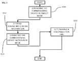
FIG. 3 is a schematic flow diagram of a method according to an embodiment of the subject application. - Because the illustrated embodiments of the subject application may for the most part, be composed of mechanisms, electronic components and circuits known to those skilled in the art, details will not be explained in any greater extent than that considered necessary for the understanding and appreciation of the underlying concepts of the subject application, in order not to obfuscate or distract from the teachings of the subject application.
- However, for the sake of clarity, it will be briefly described how conventional Zigbee Light Link (ZLL) Touchlink is working. First, it is important to note that ZLL standard specifies two general categories of devices: ZLL lighting devices and ZLL controller devices. Lighting devices may include on/off light, dimmable light, color light, extended color light, and color temperature light, for instance. On the other end, controller devices may include light switches (e.g. on walls), occupancy sensors, remote control unit(s), smart phones, computing devices (e.g. PC or tablet). In ZLL networks, a controller device is termed an 'end-device' while a lighting device is termed a 'router'. Namely, an end-device has no capability of routing messages through a ZLL network while a router is capable of routing messages through a ZLL network. Touchlink, on the other hand, is basically the user operation of holding one controller device (i.e. the "initiator") physically close to one lighting device (i.e. the "target") in order to facilitate network connection between the two. In cases where the target already belongs to an existing ZLL network, the ZLL specification stipulates that during Touchlink, the initiator first sends a 'Join network as Router' command to the target. Then, in response to the foregoing command, the target issues a 'leave' command to the existing ZLL network before it can become part of the initiator's network. This operation is sometimes termed "stealing" a target (e.g. lighting device) from an existing network by an initiator (e.g. controller device) of another network through Touchlink. One should understand that such mechanism was elaborated purposely for consumer lighting applications. For example, where a consumer owns a controller device, every time he/she buys a new lighting device, the ZLL standard provides the consumer with the ability to control the newly acquired lighting device with the existing controller device through Touchlink. This way, whatever network the acquired lighting device was associated with prior Touchlink, the newly acquired lighting device would need to leave that former network before joining the existing network controlled by the existing controller device. However, where the existing controller device is lost or broken and that a new one is acquired, the newly acquired controller device is required to Touchlink with every single lighting device of the existing ZLL network in order to take control over them. As this can be quite bothersome and annoying, it is herein proposed an alternative Touchlink mechanism which may alleviate some of the above mentioned problems.
- Referring to
FIG. 1 , there is diagrammatically shown therein asystem 10 according to an embodiment of the subject application. Thesystem 10 as shown comprises: - a first Zigbee Light Link (ZLL)
network 100; - one
remote control unit 200. - In the example of
FIG. 1 as shown, thefirst ZLL network 100 comprises one ormore lighting devices 120 and onecommissioning device 110. Thelighting devices 120 and thecommissioning device 110 ofFIG. 1 are ZLL routers which are capable of routing messages through thefirst ZLL network 100. Namely, thelighting devices 120 and thecommissioning device 110 can communicate together without the need of a Zigbee coordinator as already explained above. Also, thelighting devices 120 and thecommissioning device 110 are part of the same Personal Area Network (PAN) with the same PAN ID. InFIG. 1 , alllighting devices 120 are bound to thecommissioning device 110. The exemplary one ormore lighting devices 120 may be lamps, LED fixtures, light bulbs, projectors or any combination thereof, for instance. In an example, thecommissioning device 110 may be embodied in a wall switch panel which may comprise one switch button, for instance. Since thecommissioning device 110 and thelighting devices 120 can communicate together, the switch button may be used to switch on or off all thelighting devices 120 of thefirst ZLL network 100 when needed. In another example, the commissioning device may be fixed or removable. In addition, thelighting devices 120 and thecommissioning device 110 may be mains-powered, for instance. - In
FIG. 1 , theremote control unit 200 as shown comprises: - one
controller device 210; and, - one
communication apparatus 220 such as a smartphone or a tablet. - Also, the
remote control unit 200 is not part of thefirst ZLL network 100. For instance, theremote control unit 200 may be a factory new device or may be part of a second ZLL network different from thefirst ZLL network 100. Theexemplary controller device 210 ofFIG. 1 is a ZLL end-device node which thus has no capability of routing messages through a ZLL network, as already explained above. InFIG. 2 , thecontroller device 210 comprises afirst processing unit 211 such as a processor and operable to generate at least a first control message. For instance, the first control message may be compliant with an OSI standard format (e.g. MAC, Medium Access Control, standard format) or a ZLL standard format message. In an example, the first control message may comprise a first information representative of the initiation by thecontroller device 210 of ZLL mechanisms such as Touchlink or Binding. Thecontroller device 210 further comprises atransceiver 212 operably coupled to thefirst processing unit 211 and operable to: - transmit at least the first control message; and/or,
- receive at least a second control message.
- For instance, the second control message may be compliant with an OSI standard format (e.g. MAC standard format) or a ZLL standard format message. In an example, the second control message may comprise a second information representative of the set-up of ZLL mechanisms, such as Touchlink or Binding, at the level of the
controller device 210. Thecontroller device 210 may be an electronic device such as a dongle adapted to be removably coupled to thecommunication apparatus 220. For instance, thecontroller device 210 may be removably coupled to a conventional port of thecommunication device 220 such as an USB port or a jack port. In addition, thecontroller device 210 may be battery-powered, for instance. InFIG. 2 , thecommunication apparatus 220 comprises: - one
second processing unit 221 such as a processor; and, -
software elements 222. - In the example of
FIG. 2 thesecond processing unit 221 is operably coupled to thesoftware elements 222 and is adapted to generate at least one control command directed to thecontroller device 210. For example, the control command may have been generated in response to an event occurring in the software elements. Namely, the software elements may provide a graphical user interface which provides a button that can be actioned by a user of thecommunication apparatus 220 and that would trigger the generation of the control command. For example, the button in the graphical user interface may be associated with the initiation of ZLL mechanisms such as Touchlink or Binding. Therefore, the control command may be a Touchlink initiation control command or a Binding initiation control command, for instance. Referring toFIG. 2 , the first control message may be generated in response to the reception of the control command from thecommunication apparatus 220. In the example as shown, thesecond processing unit 221 is also further adapted to generate at least one set-up command directed to the software elements. For example, the set-up command may have been generated in response to the reception of the second control message at the level of thecontroller device 210. Namely, the software elements may provide in the graphical user interface a window wherein the set-up command associated with the second control message are displayed such that a user of thecommunication apparatus 220 may be aware about the set-up of ongoing ZLL mechanisms. For instance, parameters needed to perform Touchlink or Binding may be the displayed in the window of the graphical user interface. Therefore, the set-up command may be a Touchlink set-up control command or a Binding set-up control command, for instance. - In the example of
FIG. 1 , thecontroller device 210 is adapted to Touchlink with thecommissioning device 110. However, in the proposed Touchlink procedure, thecontroller device 210, which is an end-device, is not part of thefirst ZLL network 100 and is the "initiator" while thecommissioning device 110, which is a router, is the "target". In an example, Touchlink may be initiated by approaching thecontroller device 210 at close-proximity to thecommissioning device 110 and e.g. pressing a button situated on the graphical user interface of the associatedcommunication device 220 or pressing a button located on thecommissioning device 110. In response to that action and in contrast with conventional Touchlink procedure, in the proposed Touchlink procedure thecontroller device 210 is directly joined to thefirst ZLL network 100. Indeed, in conventional Touchlink procedure, it is not permitted to do so, as already explained above since Touchlink has to be made with every single lighting devices of thefirst ZLL network 100. - To summarise, the foregoing problem addressed by the subject application may be solved by allowing a
controller device 210 to directly join a first ZLL network while in conventional Touchlink procedure, it would have been required to Touchlink with everylighting devices 120 of thefirst ZLL network 100. In other words with the proposed solution, acontroller device 210 is able to commission more than onelighting devices 120, belonging to afirst ZLL network 100, with a single Touchlink with thecommissioning device 110 whereas in conventional Touchlink procedure, it would have been necessary to perform as many Touchlink procedures as there are lightingdevices 120 in thefirst ZLL network 100. As can be seen, the proposed solution is quite convenient and practical. However it drastically differs from conventional mechanism. In fact, the ZLL specification does not prescribe the ability to add a factorynew controller device 210 or already belonging to a ZLL network, to another ZLL network. Indeed, the ZLL standard only considers the case where the initiator is already part of thefirst ZLL network 100. Namely in that case, with conventional Touchlink, the initiator which is already part of the network first sends a 'Join network as End-Device' command to the target. Then, in response to the foregoing command, the target joins the existing network. In contrast, the proposed solution of the subject application addresses the case where the initiator is not part of thefirst ZLL network 100 that may have been pre-commissioned and to which it wishes to join. The proposed solution is made possible by the particular arrangement of thecommissioning device 110. Namely, thecommissioning device 110 is router which is already part of theZLL network 100 prior the initiation of Touchlink and which may easily communicate withlighting devices 120 of theZLL network 100. Therefore, it is mainly the addition of thecommissioning device 110 which allows the ability of easily joining thecontroller device 210 to thefirst ZLL network 100. - Referring now to
FIG. 2 , thecommissioning device 110 comprises atarget module 111 operable to cause thecommissioning device 110 to operate in a target mode during Touchlink between thecommissioning device 110 and thecontroller device 210. As already explained earlier, Touchlink in the present subject application is initiated by thecontroller device 210 which is not part of thefirst ZLL network 100 prior the initiation of Touchlink. In an example, initiation of Touchlink could be performed by having thecontroller device 210 sending a request message to thecommissioning device 110 for joining theZLL network 100. For instance, the joining information may be sent via the first control message. In response to the request message, thecommissioning device 110 may join thecontroller device 210 to theZLL network 100. In an example, thecommissioning device 110 may join thecontroller device 210 by providing thecontroller device 210 with joining information associated with theZLL network 100 such as network parameters (e.g. PAN ID (Personal Area Network ID), network key). For instance, the joining information may be sent via the second control message and may later be converted to a set-up command usable at thesoftware elements level 222. At this moment, the controller is not yet on thefirst ZLL network 100. However, communication is possible since it can occur at the MAC level, for instance. Then, based on the provided network parameters, thecontroller device 210 would be able to join thefirst ZLL network 100. This means that thecontroller device 210 would be part of thefirst ZLL network 100 and thus may obtain an IP (Internet Protocol) address for example. One of ordinary skills in the art of communication networks should note that in the proposed Touchlink procedure, where thecontroller device 210 was associated with second ZLL network different from thefirst ZLL network 100, thecontroller device 210 would have to leave the second ZLL network before joining thefirst ZLL network 100. Indeed, in ZLL specification, acontroller device 210 may only be associated with a single network. - Referring to
FIG. 2 , thecommissioning device 110 further comprises: - a
memory unit 113 such as a flash memory unit or the like; and, - a
provider module 112. - In
FIG. 2 , thememory unit 113 is operable to store at least the joining information associated with thefirst ZLL network 100 such as the PAN ID or the unique network key. In the example ofFIG. 2 , theprovider module 112 is operably coupled to thememory unit 111. Further, theprovider module 112 is operable to cause thecommissioning device 110 to operate in a provider mode during Touchlink, wherein thecommissioning device 110 is capable of providing at least the joining information to thecontroller device 210 in response to thecontroller device 210 initiating Touchlink with thecommissioning device 110. Then, based on the provided network parameters, thecontroller device 210 is able to join thefirst ZLL network 100. In an example, the joining information may be provided to thecontroller device 210 via the second control message. Later, in response to the reception of the second control message at thecontroller device 210 level, initiating Touchlink is performed by having thecontroller device 210 sending the first control message to thecommissioning device 110. - In an embodiment, while the commissioning device is in the provider mode and when the
controller device 210 has joined thefirst ZLL network 100, thecommissioning device 110 further provides to thecontroller device 210 binding information associated with at least onelighting device 120 and/or with at least one group oflighting devices 120 of the network. In an example, the binding information may be stored in thememory unit 113. In another example, thecommissioning device 110 may have been preconfigured to allow the providing of binding information only associated withspecific lighting devices 120 and not with the other ones which may be considered to be locked for control by acontroller device 210. In another example, the binding information may comprise network identification information, physical location information and/or service information (e.g. lighting devices' capabilities, level of battery) of onemore lighting devices 120 of thefirst ZLL network 100. In fact, after thecontroller device 210 has joined the existingnetwork 100, it still does not have control over thelighting devices 120 and thus binding is necessary. Indeed, binding is the mechanism of attaching or connecting a ZLL node to another ZLL one or to a group of ZLL nodes. Therefore, based on the binding information (e.g. source ZLL node, destination ZLL node, and cluster ID) thecontroller device 210 is capable of being "bound" to one or more lighting device(s) 120 within thefirst ZLL network 100. Starting from there, thecontroller device 210 may control thelighting devices 120, for instance by sending the first control message over thefirst ZLL network 100 in response to the generation of control commands by thecommunication apparatus 220. - In another embodiment of the subject application, when the
controller device 210 has joined the network and Touchlink has been completed, thecommissioning device 110 may further comprise atimer module 114. In the example ofFIG. 2 , thetimer module 114 is operable to: - set a predetermined time,
- calculate a time during which the controller has been connected to the
first ZLL network 100; and,- determine whether the calculated time is more than the predetermined time.
- In indoor environment, for instance, let's consider the case of a meeting room which access can be shared among several users and wherein each of them is owning a controlling device such as the
remote control unit 200. Let's consider also that the meeting comprises thecommissioning device 110 and a plurality of Zigbee devices such as the lighting devices 120 (e.g. lamps, screen for a retro projector and blind/curtain at the windows the meeting room), all belonging to the same network such as thefirst ZLL network 100. With the proposed solution, when a user enters the meeting room, commissioning can be performed by "touchlinking" theremote control unit 200 with thecommissioning device 110. During Touchlink, theremote control unit 200 may send a request for joining the network to thecommissioning device 110. In response to the request, the commissioning device may send joining information to theremote control unit 200 that would be used to join the network. After, theremote control unit 200 has joined thenetwork 100; thecommissioning device 110 may provide binding information to theremote control unit 200. For instance, location information may be provided, such that thecommunication apparatus 210 of theremote control unit 200 may display it on the graphical user interface (e.g. on a map window representing the room in which the network is installed). This way, the user of theremote control unit 200 may have the ability to choose on the map which lighting device(s) 110 he/she wishes to be bound with. The information may also indicate other devices that can be operated by the same interface, for example a screen, a projector, the air conditioning system of the room so that these other devices may also be controlled through the same user interface. That information may then be used by theremote control unit 200 in binding with the selected lighting device(s) 110. When Touchlink has been completed, thetimer module 114 of thecommissioning device 110 may be used to disconnect theremote control unit 200 from thefirst ZLL network 100 after a predetermined time of connection has lapsed. Indeed, since the meeting room is shared by several users, with the proposed solution it would be possible to book the meeting room for a given period (e.g. 30 minutes, 1 hour or one whole day) such that during that period, theremote control unit 200 is able to control thelighting devices 110 of thefirst ZLL network 100. However, after the predetermined time has lapsed, theremote control unit 200 would be disconnected and thus won't be able to control thelighting devices 110 anymore. In an example, the information of disconnection may be sent to theremote control unit 200 by thecommissioning device 110 through the second control message. In another example, theremote control unit 200 may set the predetermined time of connection via the transmission of the first control message to thecommissioning device 110. In yet another example, theremote control unit 200 may periodically determine its position with reference tocommissioning device 110 and/or thelighting devices 120 of the ZLL network. This way, where theremote control 200 is outside a predetermined zone away from thecommissioning device 110 and/or thelighting devices 120, the remote control device may delete all its references to the ZLL network. For instance, the position determination could be done by an energy detection scan. - In outdoor environment, for instance, let's consider the case of a public park having lighting decorations that can be controlled by different users of the park. The lighting decorations may comprise a
commissioning device 110 and a plurality oflighting devices 120 that may have been already commissioned to the same ZLL network such as thefirst ZLL network 100. The users may control the lighting decorations in order to create specific lighting experience in a dedicated part of the park or throughout the park (e.g. having thelighting device 120 showing the shape of different animals or insects like a butterfly). For instance, a user having acommunication apparatus 220 such as a tablet may plug acontroller device 210 to it, thus creating a controlling device of the network such as theremote control unit 200. The user may then downloaddedicated software elements 222 onto the tablet in order to generate control commands for instance. For instance, both thecontroller device 210 and thededicated software elements 222 may be provided by the park, as a rental service payable or free of charge, for instance. After that Touchlink has been performed with thecommissioning device 110, the user may be able to control one or more lighting devices of the ZLL network. Later, after a predetermined time has lapsed, the controller device may be disconnected from the ZLL network. This way, subsequent users may be able to control the ZLL network as well. - Referring now to
FIG. 3 , there is diagrammatically shown therein a flow diagram of a method according to an embodiment of the subject application and with regard tosystem 10 ofFIG. 1 . - In S300, it is operated the
commissioning device 110 in the target mode during a Touchlink established between thecommissioning device 110 and acontroller device 210, as already explained above. - In S310, it is stored, at the
commissioning device 110, joining information associated with thefirst ZLL network 100 and binding information associated with thelighting devices 120, as already explained above. - Then, in S320 it is operated the
commissioning device 110 in the provider mode where joining information and/or binding information are provided to thecontroller device 210 such that the latter can join the first ZLL network and bind with one ormore lighting devices 120 of theZLL network 100, as already explained above. - Later in S330, it is determined a disconnection time after which the
controller device 210 is caused to be disconnected from theZLL network 100, as already explained above. - The skilled person would appreciate that the proposed solution takes advantage of the existing Touchlink procedure in order to enable a
controller device 210 joining afirst ZLL network 100 without having to destroy the first ZLL network and without having to Touchlink with everysingle lighting devices 120 comprised in thefirst ZLL network 100. This way, the one ormore lighting devices 120 of thefirst ZLL network 100 may be directly controlled by the newly joinedcontroller device 210 after a single Touchlink. Thecommissioning device 110 may be configured to provide specific binding information to the controller device. This way, onlycertain lighting devices 120 of thefirst ZLL network 100 may be controlled by thecontroller device 210 while the others may stay, on purpose, uncontrollable by thecontroller device 210. Further, a timer in thecommissioning device 110 may be triggered to lapse after a given period of time where the controller may be disconnected from thefirst ZLL network 100. Therefore, it is clear that replacing a lost remote control of a ZLL network is made is easy with the proposed solution. Additionally, where a consumer has no intention of having distance control (e.g. through Internet) over the lighting devices, a ZLL control bridge/router won't be necessary since acommunication apparatus 220 such as a smartphone or a tablet can be directly integrated to thefirst ZLL network 100 thanks to thecontroller device 210 that can be operably coupled to it, thus providing ZLLremote control unit 200. - Of course, the above advantages are exemplary, and these or other advantages may be achieved by the proposed solution. Further, the skilled person will appreciate that not all advantages stated above are necessarily achieved by embodiments described herein.
- The principles of various embodiments of the invention can be implemented as hardware, firmware, software or any combination thereof. Moreover, the software is preferably implemented as an application program tangibly embodied on a program storage unit, a non-transitory computer readable medium, or a non-transitory machine-readable storage medium that can be in a form of a digital circuit, an analogy circuit, a magnetic medium, or combination thereof. The application program may be uploaded to, and executed by, a machine comprising any suitable architecture. Preferably, the machine is implemented on a computer platform having hardware such as one or more central processing units ("CPUs"), a memory, and input/output interfaces. The computer platform may also include an operating system and microinstruction code. The various processes and functions described herein may be either part of the microinstruction code or part of the application program, or any combination thereof, which may be executed by a CPU, whether or not such computer or processor is explicitly shown. In addition, various other peripheral units may be connected to the computer platform such as an additional data storage unit and a printing unit.
- The foregoing detailed description has set forth a few of the many forms that the invention can take. It is intended that the foregoing detailed description be understood as an illustration of selected forms that the invention can take and not as a limitation to the definition of the invention. It is only the claims that define the scope of this invention.
Claims (15)
- A commissioning device (110) for joining at least one controller device (210) to a first Zigbee Light Link, ZLL, network (100) having at least one lighting device (120) connected thereto,
wherein the commissioning device (110) is part of the ZLL network, the commissioning device comprising
a target module (111) operable to cause the commissioning device to operate in a target mode during a single Touchlink procedure established between at least the controller device and the commissioning device in which the commissioning device is capable of joining the controller device to the first ZLL network in response to the Touchlink procedure being initiated by the controller device;
wherein the commissioning device is adapted to transmit to the controller device a second control message including at least one joining information associated with the first ZLL network; and wherein the commissioning device is further adapted to transmit to the controller device a third control message including binding information associated with at least one lighting device and/or with at least one group of lighting devices of the network. - The commissioning device of claim 1, further comprising:- a memory unit (113) operable to store the at least one joining information associated with the first ZLL network;- a provider module (112) coupled to the memory unit and operable to cause the commissioning device to operate in a provider mode during the Touchlink procedure.
- The commissioning device of claim 2, wherein:- the memory unit is further adapted to store, while the commissioning device is in the provider mode, the binding information associated with at least one lighting device and/or with at least one group of lighting devices of the network; and,- the commissioning device is further adapted to transmit, while the commissioning device is in the provider mode, the third control message including the binding information to the controller device once the controller device has joined the network.
- The commissioning device of any one of claims 1, 2 or 3, wherein the binding information comprises network identification information, physical location information and/or service information.
- The commissioning device of any one of claims 1, 2, 3 or 4, wherein the commissioning device further comprises a timer module (114) operable to, when the controller device has joined the network and the Touchlink procedure has been completed, set a predetermined time, calculate a time during which the controller has been connected to the network, and determine whether the calculated time is more than the predetermined time.
- A controller device (210) for being joined by a commissioning device (110) to a first Zigbee Light Link, ZLL, network (100) having at least one lighting device (120) connected thereto, the controller device (210) comprising:- a first processing unit (211) operable to generate at least a first control message for initiating a single Touchlink procedure established between the commissioning device (110) operating in a target mode and the controller device (210) in which the commissioning device (210) is capable of joining the controller device to the first ZLL network;- a transceiver (212) coupled to the first processing unit and operable to transmit the first control message and to receive from the commissioning device a second control message including at least one joining information associated with the first ZLL network, the transceiver device being arranged to receive from the commissioning device a third control message including binding information associated with at least one lighting device and/or with at least one group of lighting devices of the network, wherin the controller device is operable to perform the steps of:- if the controller device was not associated to a second ZLL network prior to the initiation of the Touchlink procedure, not creating a further ZLL network during the Touchlink procedure; and,- if the controller device was associated to a second ZLL network prior to the initiation of the Touchlink procedure, causing the controller device to leave the second ZLL network during the Touchlink procedure.
- A system (10) for joining at least one controller device (210) to a first Zigbee Light Link, ZLL, network (100) having at least one lighting device (120) connected thereto, the system comprising:- the commissioning device (110) as claimed in any one of claims 1, 2, 3, 4 or 5, and- the controller device (210) of claim 6.
- The system of claim 7, wherein:- the first control message further comprises an information defining a predetermined time; and,- the second control message further comprises an information for launching a disconnection procedure from the first ZLL network.
- The system of any one of claims 7 or 8, wherein the controller device (210) is part of a remote control unit (200), said remote control unit also including a communication apparatus (220) operable in combination with the controller device (210), wherein the communication apparatus (220) comprises a second processing unit (222) adapted to generate at least one control command and/or at least one information command; and wherein:- the first processing unit (211) of the controller device (210) is operable to generate the first control message in response to the generation of the control command;- the second processing unit (222) of the communication apparatus (220) is adapted to generate the information command in response to reception of the second control message.
- A method of joining at least one controller device (210) to a first Zigbee Light Link, ZLL, network (100) having at least one lighting device (120) connected thereto, the method comprising the steps of:- providing a commissioning device (110) being part of the network; and- causing (S300) the commissioning device to operate in a target mode during a single Touchlink procedure established between at least the controller device and the commissioning device, to join the controller device to the network in response to the Touchlink procedure being initiated by the controller device;wherein the controller device receives from the commissioning device a second control message including at least one joining information associated with the first ZLL network; wherein the controller device further receives from the commissioning device a third control message including binding information associated with at least one lighting device and/or with at least one group of lighting devices of the network, the method further comprising the steps of:- if the controller device was not associated to a second ZLL network prior to the initiation of the Touchlink procedure, not creating a further ZLL network during the Touchlink procedure; and,- if the controller device was associated to a second ZLL network prior to the initiation of the Touchlink procedure, causing the controller device to leave the second ZLL network during the Touchlink procedure.
- The method of claim 10, further comprising the steps of:- storing (S310) the binding information associated with at least one lighting device and/or with at least one group of lighting devices of the network;- causing (S320) the commissioning device to operate in a provider mode during the Touchlink procedure, and to transmit the third control message including the binding information to the controller device in response to the controller device joining the network.
- The method of claim 11, wherein the binding information comprises network identification information, physical location information and/or service information.
- The method of any one of claims 10, 11 or 12, further comprising, when the controller device has joined the network and the Touchlink procedure has been completed, the steps of:- setting a predetermined time,- calculating a time during which the controller being connected to the network, and- determining (S330) whether the calculated time is more than the predetermined time.
- The method of claim 13, further comprising, when the calculated time is more than the predetermined time, the step of:causing the controller device to be disconnected from the ZLL network.
- A non-transitory computer readable medium having stored thereon instructions for causing one or more processing units to execute the method according to any one of claims 9, 10, 11, 12 or 13.
Priority Applications (1)
| Application Number | Priority Date | Filing Date | Title |
|---|---|---|---|
| EP14808872.7A EP3075206B1 (en) | 2013-11-29 | 2014-11-21 | Zigbee light link network commissioning |
Applications Claiming Priority (4)
| Application Number | Priority Date | Filing Date | Title |
|---|---|---|---|
| CN2013001474 | 2013-11-29 | ||
| EP14151219 | 2014-01-15 | ||
| EP14808872.7A EP3075206B1 (en) | 2013-11-29 | 2014-11-21 | Zigbee light link network commissioning |
| PCT/EP2014/075262 WO2015078778A1 (en) | 2013-11-29 | 2014-11-21 | Zigbee light link network commissioning |
Publications (2)
| Publication Number | Publication Date |
|---|---|
| EP3075206A1 EP3075206A1 (en) | 2016-10-05 |
| EP3075206B1 true EP3075206B1 (en) | 2017-11-01 |
Family
ID=52014025
Family Applications (1)
| Application Number | Title | Priority Date | Filing Date |
|---|---|---|---|
| EP14808872.7A Active EP3075206B1 (en) | 2013-11-29 | 2014-11-21 | Zigbee light link network commissioning |
Country Status (5)
| Country | Link |
|---|---|
| US (1) | US10797944B2 (en) |
| EP (1) | EP3075206B1 (en) |
| JP (1) | JP6479007B2 (en) |
| CN (1) | CN105960829B (en) |
| WO (1) | WO2015078778A1 (en) |
Families Citing this family (9)
| Publication number | Priority date | Publication date | Assignee | Title |
|---|---|---|---|---|
| JP6764471B2 (en) | 2015-09-04 | 2020-09-30 | シグニファイ ホールディング ビー ヴィSignify Holding B.V. | Replacement of wirelessly communicable components in luminaires |
| JP6430069B1 (en) | 2015-10-12 | 2018-11-28 | フィリップス ライティング ホールディング ビー ヴィ | Trial operation of wireless communication device |
| US10887972B2 (en) * | 2016-11-02 | 2021-01-05 | Signify Holding B.V. | Lighting troubleshooting |
| EP3340539B1 (en) * | 2016-12-22 | 2022-01-26 | Netatmo | Commissioning and personalizing devices in a local area network |
| US10306419B2 (en) | 2017-09-29 | 2019-05-28 | Abl Ip Holding Llc | Device locating using angle of arrival measurements |
| CN113170301A (en) * | 2018-12-07 | 2021-07-23 | 昕诺飞控股有限公司 | Temporarily adding light devices to an entertainment group |
| EP3935790A1 (en) * | 2019-03-08 | 2022-01-12 | Lutron Technology Company LLC | Commissioning and controlling load control devices |
| CN110719676B (en) * | 2019-09-05 | 2022-04-15 | 深圳市豪恩智能物联股份有限公司 | Illumination control method and illumination control equipment |
| WO2022157060A1 (en) * | 2021-01-25 | 2022-07-28 | Signify Holding B.V. | Device, network, method and computer program for configuring a distributed intelligence network |
Family Cites Families (21)
| Publication number | Priority date | Publication date | Assignee | Title |
|---|---|---|---|---|
| JP3437990B2 (en) * | 2000-03-17 | 2003-08-18 | インターナショナル・ビジネス・マシーンズ・コーポレーション | Communication method, communication terminal, wireless ad hoc network, and mobile phone |
| GB0313473D0 (en) * | 2003-06-11 | 2003-07-16 | Koninkl Philips Electronics Nv | Configuring a radio network for selective broadcast |
| US7667616B2 (en) * | 2005-08-24 | 2010-02-23 | Cooper Technologies Company | Electrical control system |
| US8300577B2 (en) * | 2006-03-06 | 2012-10-30 | Koninklijke Philips Electronics N.V. | Using position for node grouping |
| US20090094349A1 (en) | 2007-03-14 | 2009-04-09 | Amx, Llc | Device roaming on a zigbee network |
| JP2012501146A (en) * | 2008-08-27 | 2012-01-12 | コーニンクレッカ フィリップス エレクトロニクス エヌ ヴィ | Commissioning network system |
| KR101640243B1 (en) * | 2008-12-08 | 2016-07-18 | 코닌클리케 필립스 엔.브이. | A system and method for copying settings of a device to another device, particularly for copying settings between lamps |
| CN201355879Y (en) | 2009-01-19 | 2009-12-02 | 江苏技术师范学院 | Switch device for remote control lighting fitting based on ZigBee technology |
| TWI491300B (en) * | 2009-06-10 | 2015-07-01 | 皇家飛利浦電子股份有限公司 | Wireless network system, joining device for use in a wireless network system, method of commissioning awireless network system and computer program product |
| CN101902380B (en) | 2010-07-06 | 2012-07-11 | 浙江大学 | FF field bus control system based on ZigBee and protocol conversion method thereof |
| RU2013132521A (en) | 2010-12-14 | 2015-01-20 | Конинклейке Филипс Электроникс Н.В. | METHOD FOR ISSUING COMMANDS TO WIRELESS DEVICES |
| EP2503853B1 (en) * | 2011-03-25 | 2015-02-25 | LG Electronics Inc. | Lighting system and method for controlling the same |
| KR101100228B1 (en) * | 2011-05-25 | 2011-12-28 | 엘지전자 주식회사 | A lighting system, and a method of setting a address for a lighting device, and managing and controlling thereof |
| US9386666B2 (en) * | 2011-06-30 | 2016-07-05 | Lutron Electronics Co., Inc. | Method of optically transmitting digital information from a smart phone to a control device |
| US9054892B2 (en) * | 2012-02-21 | 2015-06-09 | Ecolink Intelligent Technology, Inc. | Method and apparatus for registering remote network devices with a control device |
| US9445480B2 (en) * | 2012-04-12 | 2016-09-13 | Lg Electronics Inc. | Lighting system, lighting apparatus, and lighting control method |
| US9191886B2 (en) * | 2012-06-01 | 2015-11-17 | Crestron Electronics Inc. | Commissioning of wireless devices in personal area networks |
| EP2685793B1 (en) * | 2012-07-12 | 2019-09-04 | LG Innotek Co., Ltd. | Lighting control method and lighting control system |
| CN102938729B (en) * | 2012-10-30 | 2016-12-21 | 山东智慧生活数据系统有限公司 | The long-range control method of intelligent gateway, intelligent domestic system and home appliance |
| EP2938022A4 (en) * | 2012-12-18 | 2016-08-24 | Samsung Electronics Co Ltd | Method and device for controlling home device remotely in home network system |
| US9413171B2 (en) * | 2012-12-21 | 2016-08-09 | Lutron Electronics Co., Inc. | Network access coordination of load control devices |
-
2014
- 2014-11-21 EP EP14808872.7A patent/EP3075206B1/en active Active
- 2014-11-21 JP JP2016534709A patent/JP6479007B2/en not_active Expired - Fee Related
- 2014-11-21 US US15/100,114 patent/US10797944B2/en active Active
- 2014-11-21 WO PCT/EP2014/075262 patent/WO2015078778A1/en active Application Filing
- 2014-11-21 CN CN201480065072.2A patent/CN105960829B/en active Active
Non-Patent Citations (1)
| Title |
|---|
| None * |
Also Published As
| Publication number | Publication date |
|---|---|
| JP6479007B2 (en) | 2019-03-06 |
| EP3075206A1 (en) | 2016-10-05 |
| WO2015078778A1 (en) | 2015-06-04 |
| US10797944B2 (en) | 2020-10-06 |
| CN105960829A (en) | 2016-09-21 |
| JP2017505562A (en) | 2017-02-16 |
| CN105960829B (en) | 2020-02-28 |
| US20170005860A1 (en) | 2017-01-05 |
Similar Documents
| Publication | Publication Date | Title |
|---|---|---|
| EP3075206B1 (en) | Zigbee light link network commissioning | |
| CN107926103B (en) | Commissioning and controlling a load control device | |
| JP2019506073A (en) | Set up and launch additional devices | |
| EP3363257B1 (en) | Commissioning of a wireless-communication enabled device | |
| US11191125B2 (en) | Commissioning in multi-hop networks by using a single-hop connection | |
| US10285247B2 (en) | Control installation for a lighting system and method for configuring and putting into service said control installation | |
| CN102625530B (en) | Light emitting diode (LED) lamplight remote control system based on institute of electrical and electronic engineers (IEEE) 802.15.4 | |
| EP3340539B1 (en) | Commissioning and personalizing devices in a local area network | |
| JP2012529833A (en) | Advanced commissioning of wireless network systems | |
| JP6584719B1 (en) | Lighting control | |
| EP3076763B1 (en) | Configuring a network connected lighting system | |
| US20210297483A1 (en) | Discovery and configuration of iot devices | |
| GB2547501A (en) | Secure network commissioning for lighting systems | |
| CN113794996A (en) | Device communication method, device control method, device communication apparatus, electronic device, and storage medium | |
| JP6144228B2 (en) | Wireless communication system and communication method using the system | |
| CN111742610A (en) | Debugging method and device using controlled joining mode | |
| JP2017060096A (en) | Operation unit and communication system | |
| EP3175586B1 (en) | Residential automation system, equipment and process that is easy to install, configure and use |
Legal Events
| Date | Code | Title | Description |
|---|---|---|---|
| PUAI | Public reference made under article 153(3) epc to a published international application that has entered the european phase |
Free format text: ORIGINAL CODE: 0009012 |
|
| 17P | Request for examination filed |
Effective date: 20160629 |
|
| AK | Designated contracting states |
Kind code of ref document: A1 Designated state(s): AL AT BE BG CH CY CZ DE DK EE ES FI FR GB GR HR HU IE IS IT LI LT LU LV MC MK MT NL NO PL PT RO RS SE SI SK SM TR |
|
| AX | Request for extension of the european patent |
Extension state: BA ME |
|
| DAX | Request for extension of the european patent (deleted) | ||
| GRAP | Despatch of communication of intention to grant a patent |
Free format text: ORIGINAL CODE: EPIDOSNIGR1 |
|
| INTG | Intention to grant announced |
Effective date: 20170510 |
|
| RIN1 | Information on inventor provided before grant (corrected) |
Inventor name: TAN, CHEN MIN Inventor name: ZHANG, FRANK Inventor name: ZHANG, SHENGLI |
|
| GRAS | Grant fee paid |
Free format text: ORIGINAL CODE: EPIDOSNIGR3 |
|
| GRAA | (expected) grant |
Free format text: ORIGINAL CODE: 0009210 |
|
| AK | Designated contracting states |
Kind code of ref document: B1 Designated state(s): AL AT BE BG CH CY CZ DE DK EE ES FI FR GB GR HR HU IE IS IT LI LT LU LV MC MK MT NL NO PL PT RO RS SE SI SK SM TR |
|
| REG | Reference to a national code |
Ref country code: GB Ref legal event code: FG4D |
|
| REG | Reference to a national code |
Ref country code: CH Ref legal event code: EP Ref country code: AT Ref legal event code: REF Ref document number: 943214 Country of ref document: AT Kind code of ref document: T Effective date: 20171115 |
|
| REG | Reference to a national code |
Ref country code: FR Ref legal event code: PLFP Year of fee payment: 4 |
|
| REG | Reference to a national code |
Ref country code: IE Ref legal event code: FG4D |
|
| REG | Reference to a national code |
Ref country code: DE Ref legal event code: R096 Ref document number: 602014016727 Country of ref document: DE |
|
| REG | Reference to a national code |
Ref country code: NL Ref legal event code: MP Effective date: 20171101 |
|
| REG | Reference to a national code |
Ref country code: LT Ref legal event code: MG4D |
|
| REG | Reference to a national code |
Ref country code: AT Ref legal event code: MK05 Ref document number: 943214 Country of ref document: AT Kind code of ref document: T Effective date: 20171101 |
|
| PG25 | Lapsed in a contracting state [announced via postgrant information from national office to epo] |
Ref country code: FI Free format text: LAPSE BECAUSE OF FAILURE TO SUBMIT A TRANSLATION OF THE DESCRIPTION OR TO PAY THE FEE WITHIN THE PRESCRIBED TIME-LIMIT Effective date: 20171101 Ref country code: LT Free format text: LAPSE BECAUSE OF FAILURE TO SUBMIT A TRANSLATION OF THE DESCRIPTION OR TO PAY THE FEE WITHIN THE PRESCRIBED TIME-LIMIT Effective date: 20171101 Ref country code: SE Free format text: LAPSE BECAUSE OF FAILURE TO SUBMIT A TRANSLATION OF THE DESCRIPTION OR TO PAY THE FEE WITHIN THE PRESCRIBED TIME-LIMIT Effective date: 20171101 Ref country code: NL Free format text: LAPSE BECAUSE OF FAILURE TO SUBMIT A TRANSLATION OF THE DESCRIPTION OR TO PAY THE FEE WITHIN THE PRESCRIBED TIME-LIMIT Effective date: 20171101 Ref country code: ES Free format text: LAPSE BECAUSE OF FAILURE TO SUBMIT A TRANSLATION OF THE DESCRIPTION OR TO PAY THE FEE WITHIN THE PRESCRIBED TIME-LIMIT Effective date: 20171101 Ref country code: NO Free format text: LAPSE BECAUSE OF FAILURE TO SUBMIT A TRANSLATION OF THE DESCRIPTION OR TO PAY THE FEE WITHIN THE PRESCRIBED TIME-LIMIT Effective date: 20180201 |
|
| PG25 | Lapsed in a contracting state [announced via postgrant information from national office to epo] |
Ref country code: RS Free format text: LAPSE BECAUSE OF FAILURE TO SUBMIT A TRANSLATION OF THE DESCRIPTION OR TO PAY THE FEE WITHIN THE PRESCRIBED TIME-LIMIT Effective date: 20171101 Ref country code: BG Free format text: LAPSE BECAUSE OF FAILURE TO SUBMIT A TRANSLATION OF THE DESCRIPTION OR TO PAY THE FEE WITHIN THE PRESCRIBED TIME-LIMIT Effective date: 20180201 Ref country code: LV Free format text: LAPSE BECAUSE OF FAILURE TO SUBMIT A TRANSLATION OF THE DESCRIPTION OR TO PAY THE FEE WITHIN THE PRESCRIBED TIME-LIMIT Effective date: 20171101 Ref country code: HR Free format text: LAPSE BECAUSE OF FAILURE TO SUBMIT A TRANSLATION OF THE DESCRIPTION OR TO PAY THE FEE WITHIN THE PRESCRIBED TIME-LIMIT Effective date: 20171101 Ref country code: GR Free format text: LAPSE BECAUSE OF FAILURE TO SUBMIT A TRANSLATION OF THE DESCRIPTION OR TO PAY THE FEE WITHIN THE PRESCRIBED TIME-LIMIT Effective date: 20180202 Ref country code: IS Free format text: LAPSE BECAUSE OF FAILURE TO SUBMIT A TRANSLATION OF THE DESCRIPTION OR TO PAY THE FEE WITHIN THE PRESCRIBED TIME-LIMIT Effective date: 20180301 Ref country code: AT Free format text: LAPSE BECAUSE OF FAILURE TO SUBMIT A TRANSLATION OF THE DESCRIPTION OR TO PAY THE FEE WITHIN THE PRESCRIBED TIME-LIMIT Effective date: 20171101 |
|
| PG25 | Lapsed in a contracting state [announced via postgrant information from national office to epo] |
Ref country code: CZ Free format text: LAPSE BECAUSE OF FAILURE TO SUBMIT A TRANSLATION OF THE DESCRIPTION OR TO PAY THE FEE WITHIN THE PRESCRIBED TIME-LIMIT Effective date: 20171101 Ref country code: CY Free format text: LAPSE BECAUSE OF FAILURE TO SUBMIT A TRANSLATION OF THE DESCRIPTION OR TO PAY THE FEE WITHIN THE PRESCRIBED TIME-LIMIT Effective date: 20171101 Ref country code: EE Free format text: LAPSE BECAUSE OF FAILURE TO SUBMIT A TRANSLATION OF THE DESCRIPTION OR TO PAY THE FEE WITHIN THE PRESCRIBED TIME-LIMIT Effective date: 20171101 Ref country code: DK Free format text: LAPSE BECAUSE OF FAILURE TO SUBMIT A TRANSLATION OF THE DESCRIPTION OR TO PAY THE FEE WITHIN THE PRESCRIBED TIME-LIMIT Effective date: 20171101 Ref country code: CH Free format text: LAPSE BECAUSE OF NON-PAYMENT OF DUE FEES Effective date: 20171130 Ref country code: SK Free format text: LAPSE BECAUSE OF FAILURE TO SUBMIT A TRANSLATION OF THE DESCRIPTION OR TO PAY THE FEE WITHIN THE PRESCRIBED TIME-LIMIT Effective date: 20171101 Ref country code: LI Free format text: LAPSE BECAUSE OF NON-PAYMENT OF DUE FEES Effective date: 20171130 |
|
| REG | Reference to a national code |
Ref country code: DE Ref legal event code: R097 Ref document number: 602014016727 Country of ref document: DE |
|
| PG25 | Lapsed in a contracting state [announced via postgrant information from national office to epo] |
Ref country code: IT Free format text: LAPSE BECAUSE OF FAILURE TO SUBMIT A TRANSLATION OF THE DESCRIPTION OR TO PAY THE FEE WITHIN THE PRESCRIBED TIME-LIMIT Effective date: 20171101 Ref country code: RO Free format text: LAPSE BECAUSE OF FAILURE TO SUBMIT A TRANSLATION OF THE DESCRIPTION OR TO PAY THE FEE WITHIN THE PRESCRIBED TIME-LIMIT Effective date: 20171101 Ref country code: SM Free format text: LAPSE BECAUSE OF FAILURE TO SUBMIT A TRANSLATION OF THE DESCRIPTION OR TO PAY THE FEE WITHIN THE PRESCRIBED TIME-LIMIT Effective date: 20171101 Ref country code: LU Free format text: LAPSE BECAUSE OF NON-PAYMENT OF DUE FEES Effective date: 20171121 Ref country code: PL Free format text: LAPSE BECAUSE OF FAILURE TO SUBMIT A TRANSLATION OF THE DESCRIPTION OR TO PAY THE FEE WITHIN THE PRESCRIBED TIME-LIMIT Effective date: 20171101 |
|
| REG | Reference to a national code |
Ref country code: BE Ref legal event code: MM Effective date: 20171130 |
|
| REG | Reference to a national code |
Ref country code: IE Ref legal event code: MM4A |
|
| PLBE | No opposition filed within time limit |
Free format text: ORIGINAL CODE: 0009261 |
|
| STAA | Information on the status of an ep patent application or granted ep patent |
Free format text: STATUS: NO OPPOSITION FILED WITHIN TIME LIMIT |
|
| PG25 | Lapsed in a contracting state [announced via postgrant information from national office to epo] |
Ref country code: MT Free format text: LAPSE BECAUSE OF NON-PAYMENT OF DUE FEES Effective date: 20171121 |
|
| 26N | No opposition filed |
Effective date: 20180802 |
|
| PG25 | Lapsed in a contracting state [announced via postgrant information from national office to epo] |
Ref country code: IE Free format text: LAPSE BECAUSE OF NON-PAYMENT OF DUE FEES Effective date: 20171121 |
|
| PG25 | Lapsed in a contracting state [announced via postgrant information from national office to epo] |
Ref country code: BE Free format text: LAPSE BECAUSE OF NON-PAYMENT OF DUE FEES Effective date: 20171130 Ref country code: SI Free format text: LAPSE BECAUSE OF FAILURE TO SUBMIT A TRANSLATION OF THE DESCRIPTION OR TO PAY THE FEE WITHIN THE PRESCRIBED TIME-LIMIT Effective date: 20171101 |
|
| PG25 | Lapsed in a contracting state [announced via postgrant information from national office to epo] |
Ref country code: MC Free format text: LAPSE BECAUSE OF FAILURE TO SUBMIT A TRANSLATION OF THE DESCRIPTION OR TO PAY THE FEE WITHIN THE PRESCRIBED TIME-LIMIT Effective date: 20171101 Ref country code: HU Free format text: LAPSE BECAUSE OF FAILURE TO SUBMIT A TRANSLATION OF THE DESCRIPTION OR TO PAY THE FEE WITHIN THE PRESCRIBED TIME-LIMIT; INVALID AB INITIO Effective date: 20141121 |
|
| PG25 | Lapsed in a contracting state [announced via postgrant information from national office to epo] |
Ref country code: MK Free format text: LAPSE BECAUSE OF FAILURE TO SUBMIT A TRANSLATION OF THE DESCRIPTION OR TO PAY THE FEE WITHIN THE PRESCRIBED TIME-LIMIT Effective date: 20171101 |
|
| PG25 | Lapsed in a contracting state [announced via postgrant information from national office to epo] |
Ref country code: TR Free format text: LAPSE BECAUSE OF FAILURE TO SUBMIT A TRANSLATION OF THE DESCRIPTION OR TO PAY THE FEE WITHIN THE PRESCRIBED TIME-LIMIT Effective date: 20171101 |
|
| PG25 | Lapsed in a contracting state [announced via postgrant information from national office to epo] |
Ref country code: PT Free format text: LAPSE BECAUSE OF FAILURE TO SUBMIT A TRANSLATION OF THE DESCRIPTION OR TO PAY THE FEE WITHIN THE PRESCRIBED TIME-LIMIT Effective date: 20171101 |
|
| PG25 | Lapsed in a contracting state [announced via postgrant information from national office to epo] |
Ref country code: AL Free format text: LAPSE BECAUSE OF FAILURE TO SUBMIT A TRANSLATION OF THE DESCRIPTION OR TO PAY THE FEE WITHIN THE PRESCRIBED TIME-LIMIT Effective date: 20171101 |
|
| REG | Reference to a national code |
Ref country code: DE Ref legal event code: R081 Ref document number: 602014016727 Country of ref document: DE Owner name: SIGNIFY HOLDING B.V., NL Free format text: FORMER OWNER: PHILIPS LIGHTING HOLDING B.V., EINDHOVEN, NL |
|
| P01 | Opt-out of the competence of the unified patent court (upc) registered |
Effective date: 20230421 |
|
| PGFP | Annual fee paid to national office [announced via postgrant information from national office to epo] |
Ref country code: GB Payment date: 20231121 Year of fee payment: 10 |
|
| PGFP | Annual fee paid to national office [announced via postgrant information from national office to epo] |
Ref country code: FR Payment date: 20231123 Year of fee payment: 10 |
|
| PGFP | Annual fee paid to national office [announced via postgrant information from national office to epo] |
Ref country code: DE Payment date: 20240129 Year of fee payment: 10 |