EP3074893B1 - Patient monitor and method for monitoring a patient - Google Patents
Patient monitor and method for monitoring a patient Download PDFInfo
- Publication number
- EP3074893B1 EP3074893B1 EP14799746.4A EP14799746A EP3074893B1 EP 3074893 B1 EP3074893 B1 EP 3074893B1 EP 14799746 A EP14799746 A EP 14799746A EP 3074893 B1 EP3074893 B1 EP 3074893B1
- Authority
- EP
- European Patent Office
- Prior art keywords
- patient
- user
- monitor
- administration system
- information
- Prior art date
- Legal status (The legal status is an assumption and is not a legal conclusion. Google has not performed a legal analysis and makes no representation as to the accuracy of the status listed.)
- Active
Links
- 238000000034 method Methods 0.000 title claims description 32
- 238000012544 monitoring process Methods 0.000 title claims description 13
- 238000004891 communication Methods 0.000 claims description 39
- 238000012545 processing Methods 0.000 claims description 20
- 238000004422 calculation algorithm Methods 0.000 claims description 13
- 230000008569 process Effects 0.000 claims description 10
- 238000004590 computer program Methods 0.000 claims description 4
- 238000013459 approach Methods 0.000 claims description 3
- 238000012790 confirmation Methods 0.000 claims description 2
- 238000005516 engineering process Methods 0.000 description 17
- 230000001360 synchronised effect Effects 0.000 description 17
- 238000005259 measurement Methods 0.000 description 15
- 238000007726 management method Methods 0.000 description 12
- 230000008859 change Effects 0.000 description 9
- 238000012552 review Methods 0.000 description 8
- 238000007796 conventional method Methods 0.000 description 5
- 238000012806 monitoring device Methods 0.000 description 5
- 230000005540 biological transmission Effects 0.000 description 4
- 230000006870 function Effects 0.000 description 4
- 238000010200 validation analysis Methods 0.000 description 4
- 238000013502 data validation Methods 0.000 description 3
- 230000001419 dependent effect Effects 0.000 description 3
- 238000001514 detection method Methods 0.000 description 3
- 206010040047 Sepsis Diseases 0.000 description 2
- 230000009471 action Effects 0.000 description 2
- 230000008901 benefit Effects 0.000 description 2
- 238000010586 diagram Methods 0.000 description 2
- 230000003993 interaction Effects 0.000 description 2
- 238000005457 optimization Methods 0.000 description 2
- 238000004458 analytical method Methods 0.000 description 1
- 230000036772 blood pressure Effects 0.000 description 1
- 238000004364 calculation method Methods 0.000 description 1
- 230000001934 delay Effects 0.000 description 1
- 238000013461 design Methods 0.000 description 1
- 230000006866 deterioration Effects 0.000 description 1
- 230000002526 effect on cardiovascular system Effects 0.000 description 1
- 230000036541 health Effects 0.000 description 1
- 230000006872 improvement Effects 0.000 description 1
- 238000002955 isolation Methods 0.000 description 1
- 230000007246 mechanism Effects 0.000 description 1
- 230000006855 networking Effects 0.000 description 1
- 230000003287 optical effect Effects 0.000 description 1
- 230000029058 respiratory gaseous exchange Effects 0.000 description 1
- 238000012216 screening Methods 0.000 description 1
- 238000012546 transfer Methods 0.000 description 1
- 230000001960 triggered effect Effects 0.000 description 1
Images

Classifications
-
- G—PHYSICS
- G16—INFORMATION AND COMMUNICATION TECHNOLOGY [ICT] SPECIALLY ADAPTED FOR SPECIFIC APPLICATION FIELDS
- G16H—HEALTHCARE INFORMATICS, i.e. INFORMATION AND COMMUNICATION TECHNOLOGY [ICT] SPECIALLY ADAPTED FOR THE HANDLING OR PROCESSING OF MEDICAL OR HEALTHCARE DATA
- G16H40/00—ICT specially adapted for the management or administration of healthcare resources or facilities; ICT specially adapted for the management or operation of medical equipment or devices
- G16H40/60—ICT specially adapted for the management or administration of healthcare resources or facilities; ICT specially adapted for the management or operation of medical equipment or devices for the operation of medical equipment or devices
- G16H40/67—ICT specially adapted for the management or administration of healthcare resources or facilities; ICT specially adapted for the management or operation of medical equipment or devices for the operation of medical equipment or devices for remote operation
-
- G—PHYSICS
- G16—INFORMATION AND COMMUNICATION TECHNOLOGY [ICT] SPECIALLY ADAPTED FOR SPECIFIC APPLICATION FIELDS
- G16H—HEALTHCARE INFORMATICS, i.e. INFORMATION AND COMMUNICATION TECHNOLOGY [ICT] SPECIALLY ADAPTED FOR THE HANDLING OR PROCESSING OF MEDICAL OR HEALTHCARE DATA
- G16H10/00—ICT specially adapted for the handling or processing of patient-related medical or healthcare data
- G16H10/60—ICT specially adapted for the handling or processing of patient-related medical or healthcare data for patient-specific data, e.g. for electronic patient records
-
- G—PHYSICS
- G16—INFORMATION AND COMMUNICATION TECHNOLOGY [ICT] SPECIALLY ADAPTED FOR SPECIFIC APPLICATION FIELDS
- G16H—HEALTHCARE INFORMATICS, i.e. INFORMATION AND COMMUNICATION TECHNOLOGY [ICT] SPECIALLY ADAPTED FOR THE HANDLING OR PROCESSING OF MEDICAL OR HEALTHCARE DATA
- G16H40/00—ICT specially adapted for the management or administration of healthcare resources or facilities; ICT specially adapted for the management or operation of medical equipment or devices
- G16H40/60—ICT specially adapted for the management or administration of healthcare resources or facilities; ICT specially adapted for the management or operation of medical equipment or devices for the operation of medical equipment or devices
- G16H40/63—ICT specially adapted for the management or administration of healthcare resources or facilities; ICT specially adapted for the management or operation of medical equipment or devices for the operation of medical equipment or devices for local operation
-
- G—PHYSICS
- G16—INFORMATION AND COMMUNICATION TECHNOLOGY [ICT] SPECIALLY ADAPTED FOR SPECIFIC APPLICATION FIELDS
- G16H—HEALTHCARE INFORMATICS, i.e. INFORMATION AND COMMUNICATION TECHNOLOGY [ICT] SPECIALLY ADAPTED FOR THE HANDLING OR PROCESSING OF MEDICAL OR HEALTHCARE DATA
- G16H80/00—ICT specially adapted for facilitating communication between medical practitioners or patients, e.g. for collaborative diagnosis, therapy or health monitoring
-
- H—ELECTRICITY
- H04—ELECTRIC COMMUNICATION TECHNIQUE
- H04L—TRANSMISSION OF DIGITAL INFORMATION, e.g. TELEGRAPHIC COMMUNICATION
- H04L63/00—Network architectures or network communication protocols for network security
- H04L63/08—Network architectures or network communication protocols for network security for authentication of entities
-
- G—PHYSICS
- G16—INFORMATION AND COMMUNICATION TECHNOLOGY [ICT] SPECIALLY ADAPTED FOR SPECIFIC APPLICATION FIELDS
- G16H—HEALTHCARE INFORMATICS, i.e. INFORMATION AND COMMUNICATION TECHNOLOGY [ICT] SPECIALLY ADAPTED FOR THE HANDLING OR PROCESSING OF MEDICAL OR HEALTHCARE DATA
- G16H15/00—ICT specially adapted for medical reports, e.g. generation or transmission thereof
-
- G—PHYSICS
- G16—INFORMATION AND COMMUNICATION TECHNOLOGY [ICT] SPECIALLY ADAPTED FOR SPECIFIC APPLICATION FIELDS
- G16H—HEALTHCARE INFORMATICS, i.e. INFORMATION AND COMMUNICATION TECHNOLOGY [ICT] SPECIALLY ADAPTED FOR THE HANDLING OR PROCESSING OF MEDICAL OR HEALTHCARE DATA
- G16H50/00—ICT specially adapted for medical diagnosis, medical simulation or medical data mining; ICT specially adapted for detecting, monitoring or modelling epidemics or pandemics
- G16H50/30—ICT specially adapted for medical diagnosis, medical simulation or medical data mining; ICT specially adapted for detecting, monitoring or modelling epidemics or pandemics for calculating health indices; for individual health risk assessment
Definitions
- step S30 the patient state is assessed by measuring data, such as heart beat, temperature, respiration rate, blood pressure, etc. and providing manual information, such as position at which pulse is taken, the patient posture, etc. From the available data patient-related data, such as the MEWS, is automatically calculated and output.
- data such as heart beat, temperature, respiration rate, blood pressure, etc.
- manual information such as position at which pulse is taken, the patient posture, etc.
- patient-related data such as the MEWS
Landscapes
- Engineering & Computer Science (AREA)
- Health & Medical Sciences (AREA)
- Medical Informatics (AREA)
- Biomedical Technology (AREA)
- Epidemiology (AREA)
- General Health & Medical Sciences (AREA)
- Primary Health Care (AREA)
- Public Health (AREA)
- General Business, Economics & Management (AREA)
- Business, Economics & Management (AREA)
- Pathology (AREA)
- Computer Hardware Design (AREA)
- Computer Security & Cryptography (AREA)
- Computing Systems (AREA)
- General Engineering & Computer Science (AREA)
- Computer Networks & Wireless Communication (AREA)
- Signal Processing (AREA)
- Measuring And Recording Apparatus For Diagnosis (AREA)
- Medical Treatment And Welfare Office Work (AREA)
Description
- The present invention relates to a patient monitor and a corresponding method for monitoring a patient.
- Clinical care is based on information sharing across multiple care roles, including physician, nurse, patient, family, etc., to coordinate care. In many settings today, there is an overload of care information that may not be known to all members of the team, may not be relevant at a given decision point, or is relevant and is not known to the decision member at the time of decision.
- Further, the care team is generally mobile and not physically looking at data represented in a central administration system for the patient of interest, such as EMRs (Electronic Medical Records) stored in a central server of a hospital, at the decision time. This creates an environment where errors are made due to incomplete knowledge of existing data, and workflow is impeded as the user needs to "drill" into the vast EMR to get the data, and timely collaboration with the rest of the care team delays good decision making and timely and correct care plan.
- Patient monitoring devices (herein also called patient monitors) are contributing to this workflow today as measurement devices of vital signs and providing alarming and scoring based on the captured vital signs. In case a caregiver decides to visit a patient, vital signs, alarms and scores are available for review.
-
US 6,600,421 discloses a system to automatically locally control a device according to preferences of a user entering a local area of the device from a remote area. The system provides a sensor generating measurement information based upon a patient parameter measured by the sensor and a processor managing local output of the measurement information according to automatically detected control signals locally and wirelessly transmitted from a transmitter entering a local area of the sensor from a remote area. The control signals include identification of a user and the transmitter travels with the user entering the local area of the sensor from a remote area so that the processor can manage local output of the measurement information according to stored preferences of the user. The processor can also control patient parameter measurements according to the preferences of the user. -
WO 2006/051464 A1 discloses a wireless patient point-of-care network including a plurality of medical devices each with a wireless communication interface. Each medical device is configured to provide at least one medical service to a patient. A patient identification device is associated with the patient. The patient identification device includes a wireless communication interface in communication with the wireless communication interfaces of the medical devices. The patient identification device performs a patient identification service that wirelessly associates the medical devices with the patient. - It is an object of the present invention to provide a patient monitor and a corresponding method for monitoring a patient with improved functionalities that particularly improve and ease the work of caregivers at the point of care.
- In a first aspect of the present invention a patient monitor is presented as defined in claim 1.
- In a further aspect of the present invention a corresponding method is presented as defined in claim 14.
- In yet further aspects of the present invention, there is provided a computer program as defined in
claim 15. - Preferred embodiments of the invention are defined in the dependent claims. It shall be understood that the claimed method and computer program have similar and/or identical preferred embodiments as the claimed patient monitor and as defined in the dependent claims.
- The proposed patient monitor and the proposed method represent a new class of device and method, respectively, allowing for vital signs taking, alarming, scoring and having access to complete patient context (e.g. EMR data) at the point of care (POC) of the patient monitor. Access to the complete patient context of patient data is e.g. granted by a caregiver management based on configurable point of care permissions to make sure a certain caregiver is allowed to do a dedicated set on actions on the patient monitor to increase patient safety. Information and patient context on the point of care patient monitor is presented to the caregiver and accessible to the caregiver based on the configurable point of care permissions.
- In case a caregiver is triggered by information to go to see the patient, the patient monitors connected to the patient already has or can access on demand the full patient context, while allowing for data access and validation based on individual configured caregiver skills, expressed by point of care permissions. These permissions are independent from the permissions; a caregiver may have in a centralized or mobile working environment.
- Thus, the present invention provides a unique device and method using context aware algorithms for presenting clinical information, allowing access to clinical information and communications controls, to facilitate workflow optimization and increase patient safety. The proposed patient monitor can be used in any environment including hospital, home, and during patient transport in between.
- According to a preferred embodiment said controller is configured to control said communication interface to retrieve the complete patient context information from said central administration system and other patient monitors immediately after the patient has been identified by the patient identification unit and/or to synchronize the patient monitor with the central administration system. In this way, all the relevant data that are available for a patient, including data that have been obtained at other patient monitors, are immediately available at the patient monitor at which the patient is currently identified so that all this information is immediately available for the caregiver.
- In another embodiment said controller is configured to control said communication interface to transmit obtained sensor signals, patient-related data and/or user input to said central administration system and/or to synchronize the central administration system with the patient monitor. This provides that the central administration system is updated so that other patient monitors which may be used later for the same patient, e.g. at a different point of care within a hospital, are able to immediately obtain the complete updated patient context.
- Preferably, said controller is configured to control said communication interface to transmit obtained sensor signals, patient-related data and/or user input to said central administration system after it has been obtained or updated or after confirmation by the user. Thus, the update of the central administration system can be made immediately and automatically or, alternatively, on request of the user, e.g. if certain measurements or calculations (e.g. of the patient's health score) have been confirmed by an authorized caregiver.
- Advantageously, said patient identification unit is configured to automatically identify the patient when the patient monitor approaches the patient or the patient's local area and/or to identify the patient based on user input including information related to the identity of the patient. Thus, in one embodiment the patient can be easily identified, e.g. through use of an RFID chip carried by the patient and a corresponding RFID reader integrated into the patient monitor or by use of Bluetooth or Zigbee technology. Alternatively, the user may input the patient's identity when the patient monitor is first used for the particular patient.
- In another embodiment the patient monitor further comprises a user identification unit configured for identifying the user of the patient monitor, wherein said controller is configured to control said communication interface to retrieve user context information including information related to the user, once the user has been identified by the user identification unit, available in said central administration system and/or other patient monitors from said central administration system and/or said other patient monitors, to control said user interface to output received user context and to control said processor to take received user context information into account in the processing to obtain patient-related data. The identification of the user, e.g. a caregiver like a nurse or a physician, can be made automatically using the same or similar technology as explained above for identification of the patient, or the user may identify himself through a corresponding input.
- Preferably, said user context information comprises user rights information for use by the controller
- to control the output of one or more of
- received sensor signals,
- information received from said central administration system and/or other patient monitors, and
- patient-related data by the user interface, and/or
- to control the retrieval of information from the central administration system by the communication interface, and/or
- to control the processing of sensor signals, received information and/or user input to obtain patient-related data by the processing unit.
- Said user context information preferably comprises user preferences for use by the controller
- to control the output of one or more of
- received sensor signals,
- information received from said central administration system, and/or other patient monitors and/or of patient-related data by the user interface, and
- to control the receiving of sensor signals by one or more sensors.
- In another embodiment said processor is configured to perform individual processing algorithms, in particular configurable scoring algorithms and/or auto-scheduled algorithms, to said sensor signals, received information and/or user input to obtain patient-related data. Thus, the patient monitor may act as a kind of autonomous device having a least some of the functions of the central administration system or of a conventionally used device/method to calculate patient-related data such as an early warning score. The patient monitor can generate new additional information by combining information e.g. by configurable scoring algorithms and auto scheduled algorithms.
- In another embodiment said processor is configured to synchronize and update its patient-related data after receipt of patient context information. Thus, the patient monitor is always aware of the actual patient context.
- In still another embodiment said processor is configured to process said sensor signals, received information and/or user input to obtain patient-related data irrespective if the patient monitor is connected to said central administration system or not. Thus, also in the non-connected state the patient monitor can act autonomously and process the desired patient-related data, which are only later (once the patient monitor gets connected to the central administration system) transmitted to the central administration system. This further improves the work of the caregiver since no connection to the central administration system to have the full patient context and e.g. to process obtained sensor data and calculate an early warning score.
- Further, in an embodiment said communication interface is configured to transmit patient-related data, which has been obtained while said patient monitor was not connected to said central administration system, to said central administration system once the patient monitor gets connected to said central administration system.
- According to preferred embodiments, each patient monitor identified for a certain patient at a time, allowing for having assigned multiple of the said patient monitors at the same time, perform individual algorithms on the individual available data and available patient context retrieved from and synchronized with the central administration system. The central administration system can perform individual algorithms on the individual available data and available patient context retrieved from and synchronized with the connected patient monitors, independent for multiple patients being assigned to the central administration system. Together the patient monitors and the central administration system build a synchronized patient context aware patient monitoring system. By being an equal contributor to the patient context aware patient monitoring system the individual patient monitor is always aware of the latest updated baseline of the patient context and updates individual generated data always immediately in relation of the synchronized patient context, allowing other patient monitors to immediately synchronize on their own, taking advantage in each individual available algorithm in the different patient monitors.
- Further, by being an equal contributor to the centralized distributed patient management system a patient monitor can leave and re-enter the distributed patient management system at any time and working independent while not being connected to the centralized distributed patient management system. In the moment of re-entering the centralized distributed patient management system as an equal contributor, data context received and enriched while being offline is immediately updated based on a synchronization mechanism, and the patient context enriched while being offline is immediately available to all contributors (i.e. other patient monitors and the central administration system), to allow updating the developed gaps, resulting in an distributed synchronized patient context as if the patient monitor would have been available to the distributed patient management system all the time.
- These and other aspects of the invention will be apparent from and elucidated with reference to the embodiment(s) described hereinafter. In the following drawings
-
Fig. 1 shows a schematic diagram of an embodiment of a patient monitor according to the present invention, -
Fig. 2 shows an example of the configuration of the individual permissions of a caregiver, -
Fig. 3 shows an example of derived scoring notifications synchronized to a patient monitor, -
Fig. 4 shows an example of user awareness within recommendations derived from various states of a patient scoring protocol, and -
Fig. 5 shows a flowchart of an embodiment of a method according to the present invention. -
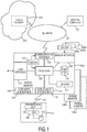
Fig. 1 shows a schematic diagram of a distributed patient management system including an embodiment of a patient monitor according to the present invention. Apparatuses 100a-100n are patient monitors in communication with a central computer (a central administration system) 102 vianetwork 104. Thenetwork 104 can be wired or wireless having a conventional topology and a conventional architecture. The architecture ofnetwork 104 can, for example, be client-server using conventional communication protocols. Thenetwork 104 can, for example, be a local area network or a wide area network, such as the Internet. Thecentral computer 102 can be a conventional computer or computing device capable of storing, displaying and processing information, and communicating with patient monitors 100a-100n by receiving and transmitting information via thenetwork 104 using conventional techniques. - The patient monitor 100a according to the present invention (which is explained in the following in more detail representative for all patient monitors 100a-100n) has a
sensor interface 106 to receive sensor signals obtained by one ormore sensors 200a-200n, such as transducers and other sensing devices, for measuring a patient parameter. Patient parameters can, for example, be cardiovascular parameters and temperature. The connection between thesensor interface 106 and thesensors 200a-200n may be established as a wireless (e.g. Bluetooth, Zigbee, WLAN) or a wired connection. - Further, a communication interface 108 (also called network interface) is provided for transmitting information to, receiving information from and synchronizing with a central administration system and/or other patient monitoring devices via a network. The
communication interface 108 is provided for communicating, using conventional (wired or wireless) techniques, with thecentral computer 102 via thenetwork 104. - A
user interface 114 is provided for reception of user input and for output of received sensor signals, information received from said central administration system and/or other patient monitoring devices and/or of patient-related data derived from said sensor signals, received information and/or user input. The local (near sensors of the patient monitor, bed/patient-side, in-room)user interface 114 preferably provides interfaces with local output devices for local information output. Thelocal output interface 114 can include, for example, a display unit visually presenting measurements (e.g., a graphical or wave presentation), a recorder presenting the measurements in a print format, and a sound unit / audio unit annunciating alarms or audibly providing the measurements, and an input/output unit for communication with other local equipment. Therefore, the patient monitor 100a can output the generated measurements to the local output interface for viewing, hearing and analysis by users (e.g., nurses and doctors). Theuser interface 114 may further include, for example, a keypad to provide manual command input for the patient monitor 100a. - A
patient identification unit 115 is provided for identifying the patient to be monitored. In the embodiment shown inFig. 1 thepatient identification unit 115 includes adetector 116 that useswireless technology 122 to automatically detect control/information signals locally transmitted from atransmitter 118 carried by the patient, when the transmitter comes within a predetermined distance from thedetector 116. When thetransmitter 118 enters a local area of the sensors patient monitor 100a from a remote area, e.g. when the patient monitor is brought to the patient for use as bedside monitor or when the patient approaches a patient monitor located at a different room, thedetector 116 automatically detects wireless control signals transmitted by thetransmitter 118. The local area can be defined, for example, as a room in which the patient is being monitored or a predetermined short distance, such as 20 feet radius, from sensor interface 106 (the bed-side patient monitor 100) according to system and application design specifications. The local area can also be defined according to or within applicable communication distance specifications of theparticular wireless technology 122 used, such as 10 meters according to Bluetooth wireless technology specification. Preferably the detection system operates within a limited range so that signals transmitted fromother transmitters 118, for example, outside of a room are detected infrequently. Thedetector 116 andtransmitter 118 can use wireless technology 122 (detection system) such as infrared technology (e.g., IrDA standard) and radio technology. Radio technologies can include, for example, wireless networking (e.g., IEEE 802.11 B standard), local radio frequency (RF) (e.g., Bluetooth and HomeRF standards) and Ultra-Wideband Radio (UWB). - Still further, the patient monitor 100a comprises a
processor 120 for processing said sensor signals, received information and/or user input to obtain patient-related data. In an embodiment saidprocessor 120 is configured to execute software to generate the patient-related data from the measurements, e.g. by performing various processing functions, such as trending, archiving, reporting and diagnostics. - A
controller 121 is provided for controlling thecommunication interface 108 to retrieve patient context information including information related to the patient, once the patient has been identified by the patient identification unit, available in said central administration system from saidcentral administration system 102 and/or other patient monitoring devices 102b-102n. Further, thecontroller 121 controls theprocessor 120 to take received patient context information into account in the processing to obtain patient-related data. - Storage devices 110 (e.g. for storing user preferences) and 112 (for generally storing data) that store information, such as memory, hard drives, or drives for removable media (e.g., CD-R, CD-ROM, CD-RW, DVD-ROM and DVD-RAM) may be provided in or connected to the patient monitor 100a by conventional techniques to provide local storage for the patient monitor 100. Alternatively, a remote storage, such as a
storage 310 in a network or in acloud 300, may be used for this purpose. - The
processor 120 is preferably in communication with and executes software to control not only thecommunication interface 108 and theprocessor 120, but also thestorage devices 110 and 112, theuser interface 114 and the detectorpatient identification unit 115, preferably using conventional techniques, so that the patient monitor 100a can automatically detect the presence of a patient in the immediate area of the patient monitor, typically a patient room. Alternatively, the patient assignment to the patient monitor can be performed in an automated way through the centralized administration system or through user interaction of a user through theuser interface 114 of the patient monitor or of the central administration system. - The
communication interface 108,user interface 114,storage devices 110 and 112, andpatient identification unit 115 are preferably integrated within the patient monitor 100a, but may (some or all) be arranged locally external to the patient monitor 100a and in communication with patient monitor 100a using conventional techniques. Theprocessor 120 and thecontroller 121 can be one or more processing units integrated with or external to patient monitor 100a. In case of being external,processor 120 andcontroller 121 would be local and in communication with patient monitor 100a using conventional interfaces and techniques. Software of an existing patient monitor can be modified to incorporate the processes of the present invention. Alternatively, a localexternal processing unit 120 andcontroller 121, which are in communication with the patient monitor and a local externalpatient identification unit 115, can execute software implementing the processes of the present invention, obviating modifying existing patient monitor software. - Preferably,
detector 116 andtransmitter 118 use wireless radio frequency technology because of radio frequency's better omni-directional communication capability than infrared's (IR) line-of-sight communication capability. For example, IR signals can be lost if the user traveling with thetransmitter 118 turns his/her back to thedetector 116, or thetransmitter 118 is covered, for example, by clothing. Further, preferablydetector 116 andtransmitter 118 use wireless radio frequency that operates at the 2.4 GHz-the Industrial-Scientific-Medical (ISM) band. Further, preferablywireless technology 122 limits interference with other devices operating in the ISM band. Further, preferablydetector 116 andtransmitter 118 cause minimal, if any, electromagnetic interference with other electronic equipment/devices. Further, preferablywireless technology 122 supports automatic linking (i.e., establishing communication) whentransmitter 118 comes into a specified distance range ofdetector 116. - In a preferred embodiment,
detector 116 andtransmitter 118 use the commercially available Bluetooth wireless technology because such technology is known to limit interference with other devises operating in the ISM band as well as cause minimal electromagnetic interference with other electronic devices. The Bluetooth wireless technology is low-power (1 milliwatt), short range (10 meters), can operate at the 2.4 GHz ISM band and supports automatic linking between mobile devices. -
Transmitter 118 preferably includes atransmission unit 124 wirelessly transmitting information signals for automatic detection bydetector 116. As discussed above,transmission unit 124 can use RF andIR wireless technology 122. In one embodiment,transmitter 118 can include aprocessor 126 executingsoftware controlling transmitter 118 according to the present invention.Transmitter 118 can also include astorage unit 128. Thestorage unit 128 can be conventional memory storing user information, such as user identification information and user preferences. Thetransmitter 118 can use conventional techniques for power, such as a battery. - Preferably, a
user identification unit 123 is provided for user identification, i.e. identification of the caregiver, such as a nurse or a clinician, who is going to use the patient monitor 100a. Theuser identification unit 123 may generally use the same technique as described above, i.e. detect a transmission unit carried by the user and may include adetector 125 that uses wireless technology to automatically detect control/information signals locally transmitted from a transmitter (not shown, but similar or identical to the transmitter 118) carried by the user, when the transmitter comes within a predetermined distance from thedetector 125. The patient monitor 100a can thus automatically detect the presence of a clinician, such as a nurse or a doctor, in the immediate area of the patient monitor, typically a patient room, and assume a "personality" consistent with the clinician's role. A patient monitor 100 can also assume an appropriate "personality" when no clinical staff is in the vicinity by providing customized default configurations. Alternatively, theuser identification unit 123 may be configured to enable a user to manually enter his identity or insert an identification card, which techniques may also be used for patient identification instead of the above described technique. - Patient monitoring environments include, for example, centrally controlled bed-side patient monitors and standalone bed-side patient monitors. In a typical system environment the patient monitors are located in patient rooms. In case of the centrally controlled bed-side patient monitors, the patient monitors include a communication interface for communicating measurements and other information to the
central administration system 102 represented by one or more central computers or servers. For example, acentral computer 102 can be connected via a network (wire or wireless) to each patient monitor via thecommunication interface 108 of the patient monitor. Thecentral computer 102 can, for example, be located at the nurse station in a hospital. A typicalcentral computer 102 includes a local (computer-side, in-room) output interface. - A patient monitor is typically controlled as follows: personnel (e.g., nurses) at the nurse station can manually input commands at the central computer to control each patient monitor. Further, commands can be manually input via the local user interface of the patient monitor to control the patient monitor. Monitor control functions can include, for example, commands manually input to set and adjust monitoring and local measurement output configurations, and to control transmission of the measurements to the central computer via the communication interface of the monitors. For example, a patient monitor's local measurement output configuration can be set to sleep mode by turning off local output of sound and display.
- Conventional patient monitors typically have only limited capabilities to process data and generate patient-related data such as an early warning score for the patient. Further, the complete patient-context, i.e. all information available for a particular patient, is generally not available at a particular patient monitor. This is different for the proposed and above described patient monitor 100a which is aware of the full patient context. Hereby, patient context awareness of the patient monitor generally means that vital signs, alarms, scores and further patient context derived from the patient monitoring device itself, other patient monitors, and the central administration system (including e.g. an EMR (Electronic Medical Record), lab and order systems, and centralized management systems), which all together form a distributed patient management system, are available to the patient monitor 100a.
- The central administration system thus works as a distributed system that synchronizes patient context retrieved from external hospital administration systems and additional / updated patient context from patient monitors where the patient has been identified at before and in the moment. Further, the central administration system takes the inputs / updates from the various sources with the patient monitor being an equal contributing and consumer element.
- The proposed patient monitor 100a further preferably provides user awareness meaning the role and permission based management of caregiver's point of care patient monitoring access rules. This allows configuring individual access to patient information at the point of care monitor allowing for user individual levels of data access, data validation, data presentation and assignment of caregivers to patients.
- In the following an embodiment of a use model of the proposed patient monitor is intended to be enabled. On a hospital ward multiple patient monitors are available to be used for vital signs taking on patients. Various deployments are used today:
- Pool Models (multi-patient workflow): the caregiver moves the patient monitor from patient to patient to take vital signs.
- A patient monitor is provided at every bedside (single patient workflow): The patient is admitted to a certain bed, and therefore to a specific monitoring equipment; the patient may be transferred from one bed to another one, e.g. to acuity change, request for isolation, etc. at any point in time.
- Today in both workflows (single patient / multiple patients) every patient monitor used has no context and no history of the patient and vital signs taking, and therefore begins with non-patient related defaults and no history. The caregiver has to review context within the patient record (manually / electronically), but the patient monitors do not have access to the current status / baseline of the patient.
- With the patient monitor and method according to the present invention, regardless which patient monitor is used on a patient, the following improvements can be achieved:
- i) Every patient monitor (immediately) synchronizes the full patient context, not only for review (prior art, electronic medical record), but for seamless monitoring, acknowledgment of (already existing and active) alarms and notifications, validation and reassessment of (already existing and active) data, continued monitoring on the current baseline (vital signs status, active alarms and notifications, EWS baseline, already validated data, ....) of this patient. This is achieved by fully modeled data, i.e. the patient monitor understands whatever data type will be synchronized and processes data of the patient as if they were generated locally. For the connected patient monitors this leads to a seamless electronic medical record of the patient as if they were connected all the time to one device, without artifacts within vital signs, alarms, notifications, pending order status, etc.
- ii) The synchronized patient context includes ADT (Admission - Discharge - Transfer) patient attribute changes, CDS (Clinical Decision Support) protocol selection for the patient, e.g. EWS (Early Warning Scoring, Sepsis Screening, Triage Acuity State), vital signs and vital trends, active alarms and alarm history.
- iii) Active notifications and notification history are provided and used, e.g. the latest EWS deterioration notifications, sepsis warnings, triage acuity change notifications, pending worklist items and history, e.g. pending vital signs or lab data requests, remote control of devices assigned to the same patient.
- iv) Therefore, the workflow of the caregiver is simplified and patient safety is further enhanced. When exchanging a patient monitor, because of e.g. a more / less acuity device is needed the current patient status (patient baseline) is immediately available on the new patient monitor and the does not need to begin from zero. The patient monitor can immediately notify on the changes of the patient from data captured on the other patient monitor. As an example, this shall be illustrated for a score change notification: The score is 1 on
patient monitor 1 and 2 onpatient monitor 2. The score change from score 1 to score 2 is announced frompatient monitor 2. The patient monitor 2 has taken over score from patient monitor 1 as baseline to announce the change of the patient. Without this enhancement the change of the score would have not been possible to be announced, because only new captured vital signs would have been available to analyze. Further, the score change can be visualized on patient monitor 1,patient monitor 2, by paging, and in the EMR, i.e. where ever the patient context is needed. The caregiver is able to review and acknowledge this score change notification on every patient monitor assigned to this patient (i.e. patient monitors 1 and 2). Thus, the full patient context is available to decide for acknowledging. Further, in a multi-patient workflow a caregiver admits a patient to the monitor and can now review the vital signs history and the pending recommendations / patient orders for that patient before taking the next steps and therefore based on the already existing status / baseline of the patient. - According to an aspect of the present invention the configuration of the individual permissions a caregiver (user) will have on the point of care patient monitor can be configured directly on the device or shared with a centralized system. Permissions can be assigned to individual caregivers or to roles summarizing a set of permissions. These roles can be assigned to the caregivers, containing the POC (Point of Care) permissions.
-
Fig. 2 illustrates an example of the configuration of the individual permissions a caregiver (user) will have on the point of care patient monitor. This configuration can be configured directly on the patient monitor or shared with a centralized system, e.g. the central administration system. Permissions can be assigned to individual caregivers or to roles summarizing a set of permissions. These roles can be assigned to the caregivers, containing the POC permissions. - According to another aspect of the present invention POC (Point of Care) user identification and authentication is enabled, allowing for users to access patient information on the point of care monitors while working standalone or connected to a system.
- According to another aspect of the present invention an execution engine (represented by the processor and/or controller) on the point of care patient monitor is provided analyzing individual user permissions and therefore granting / denying access to patient data and modifying data presentation. Examples are POC data validation, POC advisory acknowledge, etc. The user interface of these tasks on the patient monitor is only enabled in the patient monitor if the user has the appropriate permissions. As an example, after a caregiver is logged on, a patient is identified and a first MEWS (Modified Early Warning Score) is calculated, the data are checked for correctness and confirmed, e.g. by selecting a corresponding smart key ("store and validate") on the display of the patient monitor. The validated data is then sent to the central administration system. For this validation the user must have the POC data validation permission. As another example a spot check trend initiated by selecting another smart key shows the complete patient EWS history. For this the user must have the POC data review permission.
- As another example user acknowledgement may be enabled at a patient monitor as illustrated by the example of
Fig. 3 showing ascreen 30 of a patient monitor. The patient status of all notifications is synchronized back to patient monitor and available there for further caregiver action. The availability of notifications requiring caregiver interaction may be indicated visually on the display of the patient monitor, e.g. by a colored (e.g. red)exclamation mark 32. A prompt 34 may show the number of available notifications and alist 36 may show the notifications in detail. Further, thesynchronized alarm status - As still another example individual EWS recommendations may be provided at a patient monitor as illustrated by the example of
Fig. 4 showing anotherscreen 40 of a patient monitor. If a caregiver with e.g. the role and permissions of a 'Nurse-In-Charge' is logged in to the patient monitor, a recommendation 42 'Inform Nurse-In-Charge immediately' does not need to be issued. Having the knowledge of the permissions and roles of this caregiver the EWS could present a completely other set of recommendations to this caregiver. - According to another aspect of the present invention patient context awareness is provided to receive full patient context from various systems and other patient monitors to guarantee full patient context while measuring actual data on this or other devices connected and assigned to a patient. The patient status is synchronized to the patient monitor. Patient data locally stored or remote accessible and available for further processing is accessible on the patient monitor by the caregiver based on individual caregiver permissions.
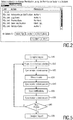
-
Fig. 5 shows a flowchart of an embodiment of a method according to the present invention. In particular, the multi-patient workflow for a caregiver with patient context synchronization functionality available, embedded in a user awareness workflow, is illustrated. - In a first step S10 the caregiver logs on to the patient monitor as explained above, e.g. by entering his identity, scanning his badge (e.g. reading a barcode), automatic recognition of his identity, etc.
- In a step S20, performed in parallel, before or after step S10, the patient is identified / selected, again by entering his identity, scanning his badge or wristband (e.g. reading a barcode), automatic recognition of his identity, etc. Preferably, only the account number is scanned, the other data of the patient (name, age, gender, date of birth, patient category, etc.) are all obtained automatically from the central administration system and are included in the dialog with the central administration system. After selecting confirm on the patient monitor, the patient is admitted. Then, an EWS protocol / patient context history already assigned to this patient is automatically synchronized for further review and validation. The EWS protocol decides which parameters have to be measured for that patient and which are the appropriate thresholds for announcing notifications.
- In step S25 the patient context is optionally synchronized. The patient context generally includes one or more of (preferably all of) the vital signs, vital signs histories, alarms, alarm histories, scores, notifications, notification histories, advisories, advisory histories, orders, order histories, work items, work item histories, status reports, patient attribute changes, protocols, protocol selection information, vital trends, alarm, sensor data requests, control data for controlling devices assigned to the patient, administration attributes selected scoring schemes, scoring protocol state. The Sequence of reviewing history data and performing the next steps with the patient is generally completely free to the user. Each step and change will be (immediately) synchronized. Preferably, the data are checked for correctness and confirmed, e.g. by selecting a corresponding smart key on the display of the patient monitor. The validated data is sent to the central administration system. A spot check trend may illustrate the complete patient EWS history.
- In step S30 the patient state is assessed by measuring data, such as heart beat, temperature, respiration rate, blood pressure, etc. and providing manual information, such as position at which pulse is taken, the patient posture, etc. From the available data patient-related data, such as the MEWS, is automatically calculated and output.
- In step S40 the patient context is optionally synchronized again.
- In step S50 active notifications regarding the particular patient synchronized to the currently used patient monitor are issued, which are ready for review and acknowledgment.
- In step S55 the patient context is optionally synchronized again.
- In step S60 the workflow continues with a new patient, i.e. returns to step S20, if desired.
- In step S70 the user is logged off, either automatically after a certain time or actively by hitting a logoff smart key. Depending on user awareness configuration access to patient data (vital signs, notifications, alarm, etc.) can now be completely prohibited, without taking away the core functionality of a patient monitor to measure new data and alarm and notify on new data.
- The present invention provides a unique methodology using context aware algorithms for presenting clinical information, audio, video and communications controls to facilitate workflow optimization and reduce alarm fatigue and information overload. The proposed device and method can be used in any environment including hospital, home, and during patient transport in between.
- According to the present invention the patient monitor is not only a source of information, which is provided to the central administration system for further processing, but the patient monitor is source and sink of information and is thus an equal contributor to the distributed patient management system formed by the central administration system and the distributed patient monitor(s). The patient monitor thus transmits information, receives information, processes information and synchronizes with the central administration system to make sure that the complete up-to-date patient context is generally always available at a patient monitor that shall be used for a particular patient and at the central administration system. It is thus generally irrelevant which contributor of the distributed patient management system generates or processes any particular information. This makes it much easier and faster for a caregiver to perform his desired task right at the place of the patient.
- While the invention has been illustrated and described in detail in the drawings and foregoing description, such illustration and description are to be considered illustrative or exemplary and not restrictive; the invention is not limited to the disclosed embodiments. Other variations to the disclosed embodiments can be understood and effected by those skilled in the art in practicing the claimed invention, from a study of the drawings, the disclosure, and the appended claims.
- In the claims, the word "comprising" does not exclude other elements or steps, and the indefinite article "a" or "an" does not exclude a plurality. A single element or other unit may fulfill the functions of several items recited in the claims. The mere fact that certain measures are recited in mutually different dependent claims does not indicate that a combination of these measures cannot be used to advantage.
- A computer program may be stored/distributed on a suitable non-transitory medium, such as an optical storage medium or a solid-state medium supplied together with or as part of other hardware, but may also be distributed in other forms, such as via the Internet or other wired or wireless telecommunication systems.
- Any reference signs in the claims should not be construed as limiting the scope.
Claims (15)
- Patient monitor for monitoring a patient comprising:- a sensor interface (106) configured for receiving sensor signals obtained by one or more sensors for measuring a patient parameter,- a communication interface (108) configured for transmitting information to and receiving information from a central administration system (102) and/or other patient monitors (100b-100n) via a network,- a user interface (114) configured for reception of user input and for output of one or more of- received sensor signals,- information received from said central administration system (102) and/or other patient monitors (100b-100n), and- patient-related data derived from said sensor signals, received information and/or user input,- a patient identification unit (115) configured for identifying the patient to be monitored,- a processor (120) configured for processing said sensor signals, received information and/or user input to obtain patient-related data, and- a controller (121) configured for controlling said communication interface (108) to retrieve patient context information including information related to the patient, once the patient has been identified by the patient identification unit (115), available in said central administration system (102) and other patient monitors (100b-100n) from said central administration system (102) and other patient monitors (100b-100n), and for controlling said processor (120) to take the retrieved patient context information and patient context information derived from the patient monitor itself into account in the processing to obtain patient-related data,wherein said patient context information comprises one or more of vital signs, vital signs histories, alarms, alarm histories, scores, notifications, notification histories, advisories, advisory histories, orders, order histories, work items, work item histories, status reports, patient attribute changes, protocols, protocol selection information, vital trends, alarm, sensor data requests, control data for controlling devices assigned to the patient, administration attributes selected scoring schemes, scoring protocol state.
- Patient monitor as claimed in claim 1,
wherein said controller (121) is configured to control said communication interface (108) to retrieve the complete patient context information from said central administration system (102) and other patient monitors (100b-100n) immediately after the patient has been identified by the patient identification unit (115) and/or to synchronize the patient monitor with the central administration system. - Patient monitor as claimed in claim 1,
wherein said controller (121) is configured to control said communication interface (108) to transmit obtained sensor signals, patient-related data and/or user input to said central administration system (102) and/or to synchronize the central administration system with the patient monitor. - Patient monitor as claimed in claim 1,
wherein said controller (121) is configured to control said communication interface (108) to transmit obtained sensor signals, patient-related data and/or user input to said central administration system (102) after it has been obtained or updated or after confirmation by the user. - Patient monitor as claimed in claim 1,
wherein said patient identification unit (115) is configured to automatically identify the patient when the patient monitor approaches the patient or the patient's local area and/or to identify the patient based on user input including information related to the identity of the patient. - Patient monitor as claimed in claim 1,
further comprising a user identification unit (123) configured for identifying the user of the patient monitor, wherein said controller (121) is configured to control said communication interface (108) to retrieve user context information including information related to the user, once the user has been identified by the user identification unit (123), available in said central administration system (102) and/or other patient monitors (100b-lOOn) from said central administration system (102) and/or said other patient monitors (100b-lOOn), to control said user interface (114) to output received user context and to control said processor (120) to take received user context information into account in the processing to obtain patient-related data. - Patient monitor as claimed in claim 6,
wherein said user context information comprises user rights information for use by the controller (121)- to control the output of one or more of- received sensor signals,- information received from said central administration system (102) and/or other patient monitors (100b-100n), and- patient-related data by the user interface, and/or- to control the retrieval of information from the central administration system (102) by the communication interface (108) and/or- to control the processing of sensor signals, received information and/or user input to obtain patient-related data by the processing unit (120). - Patient monitor as claimed in claim 6,
wherein said user context information comprises user preferences for use by the controller (121) to control the output of one or more of- received sensor signals,- information received from said central administration system (102) and/or other patient monitors (100b-100n), and- patient-related data by the user interface. - Patient monitor as claimed in claim 6,
wherein said user context information comprises user preferences for use by the controller (121) to control the receiving of sensor signals by one or more sensors. - Patient monitor as claimed in claim 1,
wherein said processor (120) is configured to perform individual processing algorithms, in particular configurable scoring algorithms and/or auto-scheduled algorithms, to said sensor signals, received information and/or user input to obtain patient-related data. - Patient monitor as claimed in claim 1,
wherein said processor (120) is configured to synchronize and update its patient-related data after receipt of patient context information. - Patient monitor as claimed in claim 1,
wherein said processor (120) is configured to process said sensor signals, received information and/or user input to obtain patient-related data irrespective if the patient monitor is connected to said central administration system (102) or not. - Patient monitor as claimed in claim 12,
wherein said communication interface (108) is configured to transmit patient-related data, which has been obtained while said patient monitor was not connected to said central administration system (102), to said central administration system (102) once the patient monitor gets connected to said central administration system (102). - Method for monitoring a patient using a patient monitor as claimed in claim 1, said method comprising:- identifying the patient to be monitored- retrieving patient context information including information related to the patient, once the patient has been identified, available in said central administration system (102) and other patient monitors (100b-100n) from said central administration system (102) and other patient monitors (100b-100n) via a network,- receiving sensor signals obtained by one or more sensors for measuring a patient parameter,- processing said sensor signals, received information and/or user input to obtain patient-related data, taking the retrieved patient context information and patient context information derived from the patient monitor itself into account in said processing,- outputting one or more of- received sensor signals,- information received from said central administration system (102) and/or other patient monitors (100b-100n), and- patient-related data derived from said sensor signals, received information and/or user input, and- transmitting received sensor signals, obtained patient-related data and/or user input to said central administration system (102) via said network,wherein said patient context information comprises one or more of vital signs, vital signs histories, alarms, alarm histories, scores, notifications, notification histories, advisories, advisory histories, orders, order histories, work items, work item histories, status reports, patient attribute changes, protocols, protocol selection information, vital trends, alarm, sensor data requests, control data for controlling devices assigned to the patient, administration attributes selected scoring schemes, scoring protocol state.
- Computer program comprising program code means for causing the patient monitor of claim 1 to carry out the steps of the method as claimed in claim 14.
Priority Applications (1)
| Application Number | Priority Date | Filing Date | Title |
|---|---|---|---|
| EP14799746.4A EP3074893B1 (en) | 2013-11-27 | 2014-11-14 | Patient monitor and method for monitoring a patient |
Applications Claiming Priority (3)
| Application Number | Priority Date | Filing Date | Title |
|---|---|---|---|
| EP13194590 | 2013-11-27 | ||
| EP14799746.4A EP3074893B1 (en) | 2013-11-27 | 2014-11-14 | Patient monitor and method for monitoring a patient |
| PCT/EP2014/074647 WO2015078710A1 (en) | 2013-11-27 | 2014-11-14 | Patient monitor and method for monitoring a patient |
Publications (2)
| Publication Number | Publication Date |
|---|---|
| EP3074893A1 EP3074893A1 (en) | 2016-10-05 |
| EP3074893B1 true EP3074893B1 (en) | 2018-08-29 |
Family
ID=49709495
Family Applications (1)
| Application Number | Title | Priority Date | Filing Date |
|---|---|---|---|
| EP14799746.4A Active EP3074893B1 (en) | 2013-11-27 | 2014-11-14 | Patient monitor and method for monitoring a patient |
Country Status (8)
| Country | Link |
|---|---|
| US (1) | US10505910B2 (en) |
| EP (1) | EP3074893B1 (en) |
| JP (1) | JP6491662B2 (en) |
| CN (1) | CN105793851B (en) |
| BR (1) | BR112016011623A2 (en) |
| ES (1) | ES2690569T3 (en) |
| RU (1) | RU2678636C1 (en) |
| WO (1) | WO2015078710A1 (en) |
Families Citing this family (9)
| Publication number | Priority date | Publication date | Assignee | Title |
|---|---|---|---|---|
| US10490049B2 (en) | 2013-12-10 | 2019-11-26 | General Electric Company | Systems and methods for identifying patient distress |
| WO2017062038A1 (en) | 2015-10-09 | 2017-04-13 | Hewlett Packard Enterprise Development Lp | Privacy preservation |
| WO2017062037A1 (en) * | 2015-10-09 | 2017-04-13 | Hewlett Packard Enterprise Development Lp | Performance tracking in a security information sharing platform |
| US10856750B2 (en) * | 2017-04-28 | 2020-12-08 | Masimo Corporation | Spot check measurement system |
| US20190341149A1 (en) * | 2018-05-07 | 2019-11-07 | Medtronic Minimed, Inc. | Augmented reality guidance for medical devices |
| EP3627517A1 (en) * | 2018-09-24 | 2020-03-25 | Koninklijke Philips N.V. | Medical monitoring system |
| US20210059597A1 (en) * | 2019-08-30 | 2021-03-04 | Hill-Rom Services, Inc. | Sepsis monitoring system |
| JP7263569B2 (en) | 2020-04-01 | 2023-04-24 | パラマウントベッド株式会社 | Device and device control method |
| GB2613624A (en) * | 2021-12-10 | 2023-06-14 | Metix Ltd | Vital signs monitor and medical device |
Family Cites Families (18)
| Publication number | Priority date | Publication date | Assignee | Title |
|---|---|---|---|---|
| US5331549A (en) * | 1992-07-30 | 1994-07-19 | Crawford Jr John M | Medical monitor system |
| US5924074A (en) * | 1996-09-27 | 1999-07-13 | Azron Incorporated | Electronic medical records system |
| JPH10323332A (en) | 1997-03-26 | 1998-12-08 | Matsushita Electric Works Ltd | Data terminal device for sickbed |
| US7860583B2 (en) | 2004-08-25 | 2010-12-28 | Carefusion 303, Inc. | System and method for dynamically adjusting patient therapy |
| US6600421B2 (en) * | 2001-07-31 | 2003-07-29 | Koninklijke Philips Electronics N.V. | System to automatically locally control a device according to preferences of a user entering a local area of the device from a remote area |
| WO2005057466A2 (en) * | 2003-12-05 | 2005-06-23 | Cardinal Health 303, Inc. | System and method fot network monitoring of multiple medical devices |
| CN101057244B (en) * | 2004-11-12 | 2016-12-28 | 皇家飞利浦电子股份有限公司 | Armarium and the auto-associating of patient and the real-time method generating patient record |
| CA2595830A1 (en) * | 2007-08-01 | 2009-02-01 | Nortel Networks Limited | A smart communications system for integration into a workflow-engaged clinical environment |
| US9514277B2 (en) | 2005-03-08 | 2016-12-06 | Koninklijke Philips N.V. | Clinical monitoring network |
| EP1913755B1 (en) * | 2005-07-29 | 2011-11-02 | Koninklijke Philips Electronics N.V. | System and method for context dependent service discovery for mobile medical devices |
| EP1927930A1 (en) | 2006-11-30 | 2008-06-04 | Sap Ag | Method and system for access control using resouce filters |
| RU2452994C2 (en) * | 2007-11-08 | 2012-06-10 | ГЛЭКСОСМИТКЛАЙН ЭлЭлСи | Systems and methods of health care product delivery |
| GB2458139A (en) * | 2008-03-06 | 2009-09-09 | Toumaz Technology Ltd | Monitoring and tracking of wireless sensor devices in a healthcare monitoring system |
| JP5430654B2 (en) | 2008-06-18 | 2014-03-05 | コーニンクレッカ フィリップス エヌ ヴェ | Personal security manager for ubiquitous patient monitoring |
| EP2318965A1 (en) * | 2008-08-28 | 2011-05-11 | Koninklijke Philips Electronics N.V. | Method and system for providing a patient identification beacon for patient worn sensors |
| BR112012016977A2 (en) | 2010-01-11 | 2017-09-26 | Card Guard Scient Survival Ltd | adhesive bandage and method for patient data control |
| CN103402423B (en) * | 2011-03-01 | 2016-09-21 | 皇家飞利浦有限公司 | Patient deterioration detects |
| US9832673B2 (en) * | 2014-07-22 | 2017-11-28 | Qualcomm Incorporated | Ultra reliable link design |
-
2014
- 2014-11-14 RU RU2016125573A patent/RU2678636C1/en active
- 2014-11-14 WO PCT/EP2014/074647 patent/WO2015078710A1/en active Application Filing
- 2014-11-14 BR BR112016011623A patent/BR112016011623A2/en not_active Application Discontinuation
- 2014-11-14 EP EP14799746.4A patent/EP3074893B1/en active Active
- 2014-11-14 ES ES14799746.4T patent/ES2690569T3/en active Active
- 2014-11-14 JP JP2016534635A patent/JP6491662B2/en active Active
- 2014-11-14 US US15/038,238 patent/US10505910B2/en active Active
- 2014-11-14 CN CN201480064940.5A patent/CN105793851B/en active Active
Also Published As
| Publication number | Publication date |
|---|---|
| ES2690569T3 (en) | 2018-11-21 |
| RU2678636C1 (en) | 2019-01-30 |
| CN105793851B (en) | 2020-06-05 |
| US20160292375A1 (en) | 2016-10-06 |
| EP3074893A1 (en) | 2016-10-05 |
| WO2015078710A1 (en) | 2015-06-04 |
| US10505910B2 (en) | 2019-12-10 |
| JP2017502721A (en) | 2017-01-26 |
| RU2016125573A (en) | 2017-12-29 |
| JP6491662B2 (en) | 2019-03-27 |
| CN105793851A (en) | 2016-07-20 |
| BR112016011623A2 (en) | 2017-08-08 |
Similar Documents
| Publication | Publication Date | Title |
|---|---|---|
| EP3074893B1 (en) | Patient monitor and method for monitoring a patient | |
| US11816973B2 (en) | Health care sanitation monitoring system | |
| US11923080B2 (en) | Medical monitoring system | |
| US20220157447A1 (en) | Medical monitoring system | |
| US11158421B2 (en) | Physiological parameter alarm delay | |
| US11488711B2 (en) | Alarm notification system | |
| JP6983279B2 (en) | Patient status display device | |
| JP2022033804A (en) | Reporting device | |
| Rezaee | Patient-Device Association and Disassociation with a Real-Time Location System |
Legal Events
| Date | Code | Title | Description |
|---|---|---|---|
| PUAI | Public reference made under article 153(3) epc to a published international application that has entered the european phase |
Free format text: ORIGINAL CODE: 0009012 |
|
| 17P | Request for examination filed |
Effective date: 20160627 |
|
| AK | Designated contracting states |
Kind code of ref document: A1 Designated state(s): AL AT BE BG CH CY CZ DE DK EE ES FI FR GB GR HR HU IE IS IT LI LT LU LV MC MK MT NL NO PL PT RO RS SE SI SK SM TR |
|
| AX | Request for extension of the european patent |
Extension state: BA ME |
|
| DAX | Request for extension of the european patent (deleted) | ||
| 17Q | First examination report despatched |
Effective date: 20170911 |
|
| GRAP | Despatch of communication of intention to grant a patent |
Free format text: ORIGINAL CODE: EPIDOSNIGR1 |
|
| INTG | Intention to grant announced |
Effective date: 20180322 |
|
| GRAS | Grant fee paid |
Free format text: ORIGINAL CODE: EPIDOSNIGR3 |
|
| GRAA | (expected) grant |
Free format text: ORIGINAL CODE: 0009210 |
|
| AK | Designated contracting states |
Kind code of ref document: B1 Designated state(s): AL AT BE BG CH CY CZ DE DK EE ES FI FR GB GR HR HU IE IS IT LI LT LU LV MC MK MT NL NO PL PT RO RS SE SI SK SM TR |
|
| REG | Reference to a national code |
Ref country code: GB Ref legal event code: FG4D |
|
| REG | Reference to a national code |
Ref country code: CH Ref legal event code: EP |
|
| REG | Reference to a national code |
Ref country code: AT Ref legal event code: REF Ref document number: 1035988 Country of ref document: AT Kind code of ref document: T Effective date: 20180915 |
|
| REG | Reference to a national code |
Ref country code: IE Ref legal event code: FG4D |
|
| REG | Reference to a national code |
Ref country code: DE Ref legal event code: R096 Ref document number: 602014031424 Country of ref document: DE |
|
| REG | Reference to a national code |
Ref country code: ES Ref legal event code: FG2A Ref document number: 2690569 Country of ref document: ES Kind code of ref document: T3 Effective date: 20181121 |
|
| REG | Reference to a national code |
Ref country code: DE Ref legal event code: R079 Ref document number: 602014031424 Country of ref document: DE Free format text: PREVIOUS MAIN CLASS: G06F0019000000 Ipc: G16Z0099000000 |
|
| REG | Reference to a national code |
Ref country code: NL Ref legal event code: MP Effective date: 20180829 |
|
| REG | Reference to a national code |
Ref country code: LT Ref legal event code: MG4D |
|
| PG25 | Lapsed in a contracting state [announced via postgrant information from national office to epo] |
Ref country code: GR Free format text: LAPSE BECAUSE OF FAILURE TO SUBMIT A TRANSLATION OF THE DESCRIPTION OR TO PAY THE FEE WITHIN THE PRESCRIBED TIME-LIMIT Effective date: 20181130 Ref country code: IS Free format text: LAPSE BECAUSE OF FAILURE TO SUBMIT A TRANSLATION OF THE DESCRIPTION OR TO PAY THE FEE WITHIN THE PRESCRIBED TIME-LIMIT Effective date: 20181229 Ref country code: RS Free format text: LAPSE BECAUSE OF FAILURE TO SUBMIT A TRANSLATION OF THE DESCRIPTION OR TO PAY THE FEE WITHIN THE PRESCRIBED TIME-LIMIT Effective date: 20180829 Ref country code: LT Free format text: LAPSE BECAUSE OF FAILURE TO SUBMIT A TRANSLATION OF THE DESCRIPTION OR TO PAY THE FEE WITHIN THE PRESCRIBED TIME-LIMIT Effective date: 20180829 Ref country code: NL Free format text: LAPSE BECAUSE OF FAILURE TO SUBMIT A TRANSLATION OF THE DESCRIPTION OR TO PAY THE FEE WITHIN THE PRESCRIBED TIME-LIMIT Effective date: 20180829 Ref country code: SE Free format text: LAPSE BECAUSE OF FAILURE TO SUBMIT A TRANSLATION OF THE DESCRIPTION OR TO PAY THE FEE WITHIN THE PRESCRIBED TIME-LIMIT Effective date: 20180829 Ref country code: BG Free format text: LAPSE BECAUSE OF FAILURE TO SUBMIT A TRANSLATION OF THE DESCRIPTION OR TO PAY THE FEE WITHIN THE PRESCRIBED TIME-LIMIT Effective date: 20181129 Ref country code: FI Free format text: LAPSE BECAUSE OF FAILURE TO SUBMIT A TRANSLATION OF THE DESCRIPTION OR TO PAY THE FEE WITHIN THE PRESCRIBED TIME-LIMIT Effective date: 20180829 Ref country code: NO Free format text: LAPSE BECAUSE OF FAILURE TO SUBMIT A TRANSLATION OF THE DESCRIPTION OR TO PAY THE FEE WITHIN THE PRESCRIBED TIME-LIMIT Effective date: 20181129 |
|
| REG | Reference to a national code |
Ref country code: AT Ref legal event code: MK05 Ref document number: 1035988 Country of ref document: AT Kind code of ref document: T Effective date: 20180829 |
|
| PG25 | Lapsed in a contracting state [announced via postgrant information from national office to epo] |
Ref country code: HR Free format text: LAPSE BECAUSE OF FAILURE TO SUBMIT A TRANSLATION OF THE DESCRIPTION OR TO PAY THE FEE WITHIN THE PRESCRIBED TIME-LIMIT Effective date: 20180829 Ref country code: LV Free format text: LAPSE BECAUSE OF FAILURE TO SUBMIT A TRANSLATION OF THE DESCRIPTION OR TO PAY THE FEE WITHIN THE PRESCRIBED TIME-LIMIT Effective date: 20180829 Ref country code: AL Free format text: LAPSE BECAUSE OF FAILURE TO SUBMIT A TRANSLATION OF THE DESCRIPTION OR TO PAY THE FEE WITHIN THE PRESCRIBED TIME-LIMIT Effective date: 20180829 |
|
| PGFP | Annual fee paid to national office [announced via postgrant information from national office to epo] |
Ref country code: IT Payment date: 20181126 Year of fee payment: 5 Ref country code: ES Payment date: 20181218 Year of fee payment: 5 |
|
| PG25 | Lapsed in a contracting state [announced via postgrant information from national office to epo] |
Ref country code: AT Free format text: LAPSE BECAUSE OF FAILURE TO SUBMIT A TRANSLATION OF THE DESCRIPTION OR TO PAY THE FEE WITHIN THE PRESCRIBED TIME-LIMIT Effective date: 20180829 Ref country code: EE Free format text: LAPSE BECAUSE OF FAILURE TO SUBMIT A TRANSLATION OF THE DESCRIPTION OR TO PAY THE FEE WITHIN THE PRESCRIBED TIME-LIMIT Effective date: 20180829 Ref country code: CZ Free format text: LAPSE BECAUSE OF FAILURE TO SUBMIT A TRANSLATION OF THE DESCRIPTION OR TO PAY THE FEE WITHIN THE PRESCRIBED TIME-LIMIT Effective date: 20180829 Ref country code: RO Free format text: LAPSE BECAUSE OF FAILURE TO SUBMIT A TRANSLATION OF THE DESCRIPTION OR TO PAY THE FEE WITHIN THE PRESCRIBED TIME-LIMIT Effective date: 20180829 Ref country code: PL Free format text: LAPSE BECAUSE OF FAILURE TO SUBMIT A TRANSLATION OF THE DESCRIPTION OR TO PAY THE FEE WITHIN THE PRESCRIBED TIME-LIMIT Effective date: 20180829 |
|
| PG25 | Lapsed in a contracting state [announced via postgrant information from national office to epo] |
Ref country code: SM Free format text: LAPSE BECAUSE OF FAILURE TO SUBMIT A TRANSLATION OF THE DESCRIPTION OR TO PAY THE FEE WITHIN THE PRESCRIBED TIME-LIMIT Effective date: 20180829 Ref country code: SK Free format text: LAPSE BECAUSE OF FAILURE TO SUBMIT A TRANSLATION OF THE DESCRIPTION OR TO PAY THE FEE WITHIN THE PRESCRIBED TIME-LIMIT Effective date: 20180829 Ref country code: DK Free format text: LAPSE BECAUSE OF FAILURE TO SUBMIT A TRANSLATION OF THE DESCRIPTION OR TO PAY THE FEE WITHIN THE PRESCRIBED TIME-LIMIT Effective date: 20180829 |
|
| REG | Reference to a national code |
Ref country code: DE Ref legal event code: R097 Ref document number: 602014031424 Country of ref document: DE |
|
| REG | Reference to a national code |
Ref country code: CH Ref legal event code: PL |
|
| PLBE | No opposition filed within time limit |
Free format text: ORIGINAL CODE: 0009261 |
|
| STAA | Information on the status of an ep patent application or granted ep patent |
Free format text: STATUS: NO OPPOSITION FILED WITHIN TIME LIMIT |
|
| PG25 | Lapsed in a contracting state [announced via postgrant information from national office to epo] |
Ref country code: MC Free format text: LAPSE BECAUSE OF FAILURE TO SUBMIT A TRANSLATION OF THE DESCRIPTION OR TO PAY THE FEE WITHIN THE PRESCRIBED TIME-LIMIT Effective date: 20180829 Ref country code: LU Free format text: LAPSE BECAUSE OF NON-PAYMENT OF DUE FEES Effective date: 20181114 |
|
| 26N | No opposition filed |
Effective date: 20190531 |
|
| REG | Reference to a national code |
Ref country code: BE Ref legal event code: MM Effective date: 20181130 |
|
| REG | Reference to a national code |
Ref country code: IE Ref legal event code: MM4A |
|
| PG25 | Lapsed in a contracting state [announced via postgrant information from national office to epo] |
Ref country code: SI Free format text: LAPSE BECAUSE OF FAILURE TO SUBMIT A TRANSLATION OF THE DESCRIPTION OR TO PAY THE FEE WITHIN THE PRESCRIBED TIME-LIMIT Effective date: 20180829 Ref country code: LI Free format text: LAPSE BECAUSE OF NON-PAYMENT OF DUE FEES Effective date: 20181130 Ref country code: CH Free format text: LAPSE BECAUSE OF NON-PAYMENT OF DUE FEES Effective date: 20181130 |
|
| PG25 | Lapsed in a contracting state [announced via postgrant information from national office to epo] |
Ref country code: IE Free format text: LAPSE BECAUSE OF NON-PAYMENT OF DUE FEES Effective date: 20181114 |
|
| PG25 | Lapsed in a contracting state [announced via postgrant information from national office to epo] |
Ref country code: BE Free format text: LAPSE BECAUSE OF NON-PAYMENT OF DUE FEES Effective date: 20181130 |
|
| PG25 | Lapsed in a contracting state [announced via postgrant information from national office to epo] |
Ref country code: MT Free format text: LAPSE BECAUSE OF NON-PAYMENT OF DUE FEES Effective date: 20181114 |
|
| PG25 | Lapsed in a contracting state [announced via postgrant information from national office to epo] |
Ref country code: TR Free format text: LAPSE BECAUSE OF FAILURE TO SUBMIT A TRANSLATION OF THE DESCRIPTION OR TO PAY THE FEE WITHIN THE PRESCRIBED TIME-LIMIT Effective date: 20180829 |
|
| PG25 | Lapsed in a contracting state [announced via postgrant information from national office to epo] |
Ref country code: PT Free format text: LAPSE BECAUSE OF FAILURE TO SUBMIT A TRANSLATION OF THE DESCRIPTION OR TO PAY THE FEE WITHIN THE PRESCRIBED TIME-LIMIT Effective date: 20180829 |
|
| PG25 | Lapsed in a contracting state [announced via postgrant information from national office to epo] |
Ref country code: HU Free format text: LAPSE BECAUSE OF FAILURE TO SUBMIT A TRANSLATION OF THE DESCRIPTION OR TO PAY THE FEE WITHIN THE PRESCRIBED TIME-LIMIT; INVALID AB INITIO Effective date: 20141114 Ref country code: MK Free format text: LAPSE BECAUSE OF NON-PAYMENT OF DUE FEES Effective date: 20180829 Ref country code: CY Free format text: LAPSE BECAUSE OF FAILURE TO SUBMIT A TRANSLATION OF THE DESCRIPTION OR TO PAY THE FEE WITHIN THE PRESCRIBED TIME-LIMIT Effective date: 20180829 |
|
| PG25 | Lapsed in a contracting state [announced via postgrant information from national office to epo] |
Ref country code: IT Free format text: LAPSE BECAUSE OF NON-PAYMENT OF DUE FEES Effective date: 20191114 |
|
| REG | Reference to a national code |
Ref country code: ES Ref legal event code: FD2A Effective date: 20210526 |
|
| PG25 | Lapsed in a contracting state [announced via postgrant information from national office to epo] |
Ref country code: ES Free format text: LAPSE BECAUSE OF NON-PAYMENT OF DUE FEES Effective date: 20191115 |
|
| PGFP | Annual fee paid to national office [announced via postgrant information from national office to epo] |
Ref country code: GB Payment date: 20231121 Year of fee payment: 10 |
|
| PGFP | Annual fee paid to national office [announced via postgrant information from national office to epo] |
Ref country code: FR Payment date: 20231123 Year of fee payment: 10 Ref country code: DE Payment date: 20231127 Year of fee payment: 10 |