EP3074844B1 - Estimating gaze from un-calibrated eye measurement points - Google Patents
Estimating gaze from un-calibrated eye measurement points Download PDFInfo
- Publication number
- EP3074844B1 EP3074844B1 EP14805286.3A EP14805286A EP3074844B1 EP 3074844 B1 EP3074844 B1 EP 3074844B1 EP 14805286 A EP14805286 A EP 14805286A EP 3074844 B1 EP3074844 B1 EP 3074844B1
- Authority
- EP
- European Patent Office
- Prior art keywords
- measurement points
- eye measurement
- scene
- points
- coordinate system
- Prior art date
- Legal status (The legal status is an assumption and is not a legal conclusion. Google has not performed a legal analysis and makes no representation as to the accuracy of the status listed.)
- Active
Links
- 238000005259 measurement Methods 0.000 title claims description 273
- 238000013507 mapping Methods 0.000 claims description 57
- 238000000034 method Methods 0.000 claims description 40
- 230000009466 transformation Effects 0.000 claims description 37
- 238000012545 processing Methods 0.000 claims description 35
- 230000002123 temporal effect Effects 0.000 claims description 9
- 238000004590 computer program Methods 0.000 claims description 8
- 238000001514 detection method Methods 0.000 claims description 4
- 230000006870 function Effects 0.000 description 7
- 238000009826 distribution Methods 0.000 description 6
- 238000005457 optimization Methods 0.000 description 6
- 230000004424 eye movement Effects 0.000 description 4
- 239000000203 mixture Substances 0.000 description 4
- 210000001747 pupil Anatomy 0.000 description 4
- 230000000007 visual effect Effects 0.000 description 4
- 230000003287 optical effect Effects 0.000 description 3
- 241000282412 Homo Species 0.000 description 2
- 230000008859 change Effects 0.000 description 2
- 230000001419 dependent effect Effects 0.000 description 2
- 230000000694 effects Effects 0.000 description 2
- 238000000844 transformation Methods 0.000 description 2
- 238000013459 approach Methods 0.000 description 1
- 230000008901 benefit Effects 0.000 description 1
- 238000004364 calculation method Methods 0.000 description 1
- 230000021615 conjugation Effects 0.000 description 1
- 238000013500 data storage Methods 0.000 description 1
- 238000013461 design Methods 0.000 description 1
- 230000003993 interaction Effects 0.000 description 1
- 239000011159 matrix material Substances 0.000 description 1
- 230000008569 process Effects 0.000 description 1
- 239000004065 semiconductor Substances 0.000 description 1
- 238000000926 separation method Methods 0.000 description 1
- 238000010008 shearing Methods 0.000 description 1
- 238000012360 testing method Methods 0.000 description 1
- 238000013519 translation Methods 0.000 description 1
Images

Classifications
-
- A—HUMAN NECESSITIES
- A61—MEDICAL OR VETERINARY SCIENCE; HYGIENE
- A61B—DIAGNOSIS; SURGERY; IDENTIFICATION
- A61B3/00—Apparatus for testing the eyes; Instruments for examining the eyes
- A61B3/10—Objective types, i.e. instruments for examining the eyes independent of the patients' perceptions or reactions
- A61B3/113—Objective types, i.e. instruments for examining the eyes independent of the patients' perceptions or reactions for determining or recording eye movement
-
- G—PHYSICS
- G06—COMPUTING; CALCULATING OR COUNTING
- G06F—ELECTRIC DIGITAL DATA PROCESSING
- G06F17/00—Digital computing or data processing equipment or methods, specially adapted for specific functions
- G06F17/10—Complex mathematical operations
- G06F17/18—Complex mathematical operations for evaluating statistical data, e.g. average values, frequency distributions, probability functions, regression analysis
-
- G—PHYSICS
- G06—COMPUTING; CALCULATING OR COUNTING
- G06F—ELECTRIC DIGITAL DATA PROCESSING
- G06F3/00—Input arrangements for transferring data to be processed into a form capable of being handled by the computer; Output arrangements for transferring data from processing unit to output unit, e.g. interface arrangements
- G06F3/01—Input arrangements or combined input and output arrangements for interaction between user and computer
- G06F3/011—Arrangements for interaction with the human body, e.g. for user immersion in virtual reality
- G06F3/013—Eye tracking input arrangements
Definitions
- the invention relates to a system and a method for enabling estimating gaze from a set of un-calibrated eye measurement points.
- the invention further relates to a computer program product comprising instructions for causing a processing subsystem to perform the method.
- Gaze estimation refers to the process of determining where a person is looking at in a predefined plane, i.e., a gaze plane.
- a gaze plane may be associated with a scene, such as, e.g., a physical scene as presented in a shopping window, or a virtual scene as provided by content displayed on a computer screen.
- gaze points the points at which a person gazes at in the scene are referred to as gaze points. Gaze estimation is increasingly important for many applications such as human-computer interaction, marketing and advertisement, and human behavior analysis.
- Gaze estimation methods generally involve calibration.
- the calibration may be camera-based (estimating the camera parameters), geometric calibration (estimating the relations between the scene components like the camera, the gaze plane, and the user), or personal calibration (determining the angle between visual and optical axes).
- An extensive overview of the different approaches of gaze estimation and their calibration can be found in " In the Eye of the Beholder: A Survey of Models for Eyes and Gaze” by D.W Hansen et al., IEEE Transactions on Pattern Analysis and Machine Intelligence, Vol. 32, Issue 3, p. 478-500, 2010 .
- US 7,657,062 B2 provides a calibration apparatus for automatically self-calibrating a set of eye tracking measurements to a reference space, said apparatus comprising: a tracking device capable of capturing a plurality of eye gaze measurements, representing a plurality of eye gaze positions; a statistical analyzer for determining a statistical distribution of said plurality of eye gaze measurements; a data storage device for storing a predetermined set of statistics data of eye movement measurements; a statistical data comparison component for comparing said statistical distribution data of said plurality of eye gaze measurements with said stored predetermined set of statistical data of eye movement measurements; and a calibration data generating component for generating a calibration data depending upon a result of said comparison.
- US 7,657,062 B2 uses statistical distribution data of which the relation to the reference space is known to calibrate the eye gaze measurements of a user.
- the predetermined statistics may take two forms. Firstly, a set of statistics may be taken for a plurality of persons in order to obtain an "average" statistical information for human users, describing the eye movement patterns of a notional average person. Such statistics are not specific to any one individual person, but may represent a notional average person based upon an average of a test sample comprising a plurality of persons. Fig. 6 of US 7,657,062 B2 shows that the notional average person gazes straight ahead with the highest probability. Secondly, statistics may be derived for measurements taken from just one individual person. In this case, the individual person may have their own particular quirks and idiosyncrasies.
- WO 2013/059940 A1 describes a method for automating a gaze tracking system calibration based on display content and/or user actions that are likely to attract the subject's gaze. The method involves obtaining gaze data, obtaining at least one key point corresponding to a portion of media content being displayed, linking the gaze data to the at least one key point, and generating one or more calibration parameters by comparing gaze data with associated ones of the at least one key point
- One of the objects of the invention is to obtain a system or method which enables the gaze of a user viewing a scene to be more accurately estimated.
- the following aspects of the invention are based on the insight that gaze patterns between different users are similar for a same scene.
- the term 'gaze pattern' refers to the spatial distribution of gaze points with respect to the scene.
- the eye measurement points of a user viewing a scene can be calibrated to the eye measurement points of another user viewing, or having viewed, the same scene. Hence, users do not need to actively participate in the calibration procedure.
- a first aspect of the invention provides a system for enabling estimating gaze of different users with respect to a scene from eye measurement points which represent un-calibrated eye measurements of the users viewing the scene, the system comprising:
- a further aspect of the invention provides a method for enabling estimating gaze of different users with respect to a scene from eye measurement points which represent un-calibrated eye measurements of the users viewing the scene, the method comprising:
- a further aspect of the invention provides a computer program product comprising instructions for causing a processor system to perform the method.
- the above measures involve obtaining at least two sets of eye measurement points of different users viewing the same scene.
- Each set of eye measurement points is indicative of the gaze pattern of a respective user when the user is viewing the scene in that they represent un-calibrated measurements from which a set of gaze points may be calculated, i.e., by calibration.
- the eye measurement points may represent changes in the user's eyes when viewing the scene. Such changes may be measured using, e.g., a video camera, a depth camera, infrared diodes, etc.
- the eye measurement points may represent gaze directions, relative iris movements or changes in descriptors extracted from the eyes.
- the eye measurement points may also take any other suitable form.
- Both sets of eye measurement points are defined as coordinates in coordinate systems which have an unknown geometric relation.
- the eye measurement points may be provided as Cartesian coordinates in planes having differently defined axes.
- both sets of eye measurement points are mutually un-calibrated in that the same coordinates in both coordinate systems may represent different measured quantities of both users, e.g., different gaze directions or different relative iris movements, and thus represent different gaze points with respect to the scene.
- a processing subsystem is provided for mapping the first set of eye measurement points and the second set of eye measurement points to a common coordinate system.
- the processing subsystem ensures that similar coordinates in the common coordinate system are established for the geometrically similar topologies of both sets of eye measurement points.
- the term 'topology', and in particular 'geometric topology' refers to the geometric relation between the eye measurement points, as indicated by, e.g., their relative position, their relative distance, etc.
- the geometric topology represents the spatial inter-relations and arrangement of eye measurement points.
- the processing subsystem calculates a scene transformation for mapping the common coordinate system to a coordinate system associated with the scene. This calculation is performed on the basis of the processing subsystem matching eye measurement points from the common coordinate system to interest points of the scene.
- the term 'interest point' refers to a point in the scene which is expected to draw a user's attention.
- a linear transformation may be calculated which minimizes a distance measure being defined as a function of the distance between the eye measurement points and the interest points of the scene.
- the inventors have recognized that different users exhibit similar gaze patterns when viewing a same scene. This assumption is supported by the publication " Learning to predict where humans look” by Judd, K. Ehinger et al, IEEE International Conference on Computer Vision (ICCV), p. 2106-2113, 2009 , in which the authors describe a database of (calibrated) eye tracking data which shows that the gaze patterns of previous users are predictive of those of new users viewing same scene.
- the invention makes use of the above recognition in that geometrically similar topologies in the eye measurement points of different users are assumed to represent a similar gaze pattern with respect to the scene.
- eye measurement points of different users may be mutually calibrated by mapping the eye measurement points to a common coordinate system in which the geometrically similar topologies match in coordinates, i.e., at least partially overlap.
- similar measured quantities of the different users e.g., similar gaze directions or similar relative iris movements
- the eye measurement points of the different users are mutually calibrated.
- the above measures have the effect that a calibration between the eye measurement points of a particular user and the scene is obtained by mapping the user's eye measurement points together with those of at least one other user jointly to a common coordinate system. The scene transformation is then calculated based on eye measurement points which have been mapped to the common coordinate system.
- the inventors have recognized that this allows the eye measurement points of a single user to be more accurately calibrated since after said mapping, distinct patterns emerge in the common coordinate system which allow the mapping to the interest points to be more accurately calculated.
- the mapping of the eye measurement points of different users to a single coordinate system reduces the influence of individual outliers in the eye measurement points of each user.
- US 7,657,062 B2 does not mutually calibrate eye measurement points relating to the viewing of a same scene but rather makes use of non-scene specific statistical data.
- US 7,657,062 B2 obtains a less accurate calibration.
- the above measures enable estimating gaze from a set of eye measurement points of the first user or the second user, in that a set of gaze points can be obtained when applying the scene transformation to the set of eye measurement points after being mapped to the common coordinate system.
- the input is arranged for obtaining a further set of eye measurement points of a further user viewing the scene, the further set of eye measurement points being obtained as coordinates in a coordinate system having an unknown geometric relation with the common coordinate system, and the processing subsystem is configured for estimating a set of gaze points from the further set of eye measurement points by:
- the eye measurement points of each further user viewing the scene may be automatically mutually calibrated with respect to those of other users viewing the scene by mapping the eye measurement points to the common coordinate system.
- the mapping makes use of the abovementioned recognition that geometrically similar topologies in the eye measurement points of different users are assumed to represent a similar gaze pattern with respect to the scene.
- the same scene transformation may then be used to estimate the set of gaze points from the further set of mapped eye measurement points. It is therefore not needed to calculate the scene transformation anew for each further individual user viewing the scene.
- the processing subsystem is configured for combining the set of mapped eye measurement points and the further set of mapped eye measurement points to obtain a set of reference points, and wherein said mapping of the further set of eye measurement points to the common coordinate system is performed by the processing subsystem matching geometrically similar topologies between the further set of eye measurement points and the set of reference points.
- a set of reference points is obtained.
- the set of reference points may represent an estimate of the common interest points of different users, which may then be mapped to the (actual) interest points in the scene.
- the set of gaze points may be more accurately estimated.
- the processing subsystem is configured for combining the set of mapped eye measurement points and the further set of mapped eye measurement points by applying a statistical filter to both sets of eye measurement points.
- Statistical filters such as rank-order filters, enable the individual outliers in the eye measurement points of different users to be effectively reduced.
- the processing subsystem is configured for including the further set of mapped eye measurement points in the set of reference points so as to iteratively buildup the set of reference points.
- the processing subsystem is configured for including further sets of eye measurement points in the set of reference points so as to iteratively buildup the set of reference points.
- the processing subsystem is configured for re-calculating the scene transformation after said including of the further set of mapped eye measurement points.
- the accuracy of the scene transformation may be improved since the influence of individual outliers may have been further reduced by the inclusion of the further set of mapped eye measurement points.
- the system may use the eye measurement points of new users viewing the scene to gradually provide a more accurate estimation of their gaze.
- the processing subsystem is configured for identifying a difference between the set of gaze points of the further user and a reference set of gaze points which is obtained by applying the scene transformation to the set of reference points.
- Differences between the gaze points of users may be highly relevant. For example, when viewing a shopping window, such differences may reflect individual preferences of users. By identifying such differences in the gaze points, the individual preferences are made visible. These may be used to later on dynamically customize the scene to each user.
- the difference comprises at least one of: a difference in temporal order of gazing at same or similar parts of the scene, and a difference in the parts of the scene at which the gazing is directed.
- the order in which a user gazes at same or similar parts of the scene may reflect their individual preferences, as does the difference in the parts of the scene at which the user's gazing is directed.
- the first set of eye measurement points and the second set of eye measurement points are obtained from users viewing different instances of the scene.
- the system thus combines the measurement data of users viewing different instances of the scene rather than viewing the same instance of the scene at different times.
- the measurement data obtained at said scenes may be combined since the users are nevertheless expected to exhibit similar gaze patterns with respect to the scenes.
- the different instances of the scene comprise at least one of: the scene at different locations, a display of the scene provided by different display devices, different types of physical display of the scene.
- the measurement data across different locations, different display devices or different types of physical display of the scene may be combined.
- the term 'different types of physical display' refers to the scenes being displayed using different physical principles, e.g., using printed paper vs. using a digital screen.
- the system further comprises a first eye measurement subsystem for obtaining the first set of eye measurement points of the first user viewing a first instance of the scene, and a second eye measurement subsystem for obtaining the second set of eye measurement points of the second user viewing a second instance of the scene, the first instance being different from the second instance.
- the eye measurement subsystems are located at different locations, and/or are differently arranged so as to obtain the measurements with respect to the scene provided by different display devices, and/or provided by different types of physical display of the scene.
- the input is arranged for obtaining an image of the scene
- the processing subsystem is configured for using a saliency detection technique to detect saliency points in the image so as to determine the interest points of the scene.
- the mapping of the first set of eye measurement points and the second set of eye measurement points to the common coordinate system comprises a linear coordinate transformation.
- a linear coordinate transformation is well suited for mapping the eye measurement points to a common coordinate system in which the geometrically similar topologies match in coordinates, i.e., at least partially overlap, while still allowing for individual differences in the eye measurement points.
- the transformation may comprise translation, rotation, shearing and scaling.
- each set of eye measurement points is constituted by a measurement of one of the group of: a gaze direction, an iris movement and a position of part of the eyes.
- the system may use various types of measurement data, including but not limited to measurement data of the aforementioned types.
- the invention enables estimating gaze from a set of eye measurement points which are indicative of a gaze pattern of a user viewing a scene.
- use is made of the insight that gaze patterns of different users are similar for a same scene.
- the invention involves obtaining different sets of eye measurement points from different users viewing the same scene.
- the different sets of eye measurement points are mapped to a common coordinate system, and thereby mutually calibrated, based on the assumption that geometrically similar topologies between the different sets of eye measurement points are to be mapped to similar coordinates in the common coordinate system as they represent a similar or same gaze pattern.
- a scene transformation for mapping the common coordinate system to a coordinate system associated with the scene can be calculated by matching eye measurement points from the common coordinate system to interest points of the scene.
- the scene transformation is thereby calculated more accurately than individually calculated scene transformations, thereby providing a more accurate estimate of the gaze points.
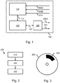
- Fig. 1 shows a system 100 comprising an input 120 for obtaining at least a first set of eye measurement points 050A of a first user viewing a scene and a second set of eye measurement points 050B of a second user viewing the scene.
- each set of eye measurement points is indicative of a gaze pattern of the respective user when viewing the scene.
- Such sets of eye measurement points may be obtained in various ways.
- the system 100 may be connected to a measurement system (not shown in Fig. 1 ) which measures, in real-time when a user views the scene, a change in the user's relative iris movement, a change in the position of the user's eyes, etc.
- measurement data 050A, 050B may be obtained from a database and represent a previously measured set of eye measurement points.
- the input 120 may constitute or be part of, e.g., a network interface or a storage interface.
- the first set of eye measurement points 050A are obtained as coordinates in a first coordinate system and the second set of eye measurement points 050B are obtained as coordinates in a second coordinate system.
- the first coordinate system and the second coordinate system have an unknown geometric relation in that it is not known how a coordinate in the first coordinate system relates to the same coordinate in the second coordinate system, i.e., whether or not it concerns a same measured quantity, and in case of the latter, what the difference in measured quantity is.
- the system 100 further comprises a processing subsystem 140.
- the processing subsystem 140 is shown to communicate with the input 120 via an exchange of messages 122, thereby enabling the processing subsystem 140 to access the first set of eye measurement points 050A and the first second of eye measurement points 050B.
- the processing subsystem 140 is configured to perform the following actions during operation of the system 100. Firstly, the processing subsystem 140 maps the first set of eye measurement points 050A and the second set of eye measurement points 050B to a common coordinate system, the mapping being based on similar coordinates being established in the common coordinate system for geometrically similar topologies of both sets of eye measurement points.
- the processing subsystem 140 further calculates a scene transformation for mapping the common coordinate system to a coordinate system associated with the scene, the calculating involving matching eye measurement points from the common coordinate system to interest points of the scene.
- Fig. 1 shows such an optional aspect of the system 100 in that the system 100 comprises an output 160 for outputting data such as a set of gaze points 060X.
- the set of gaze points 060X which may be estimated by the processing subsystem 140 by mapping a set of eye measurement points, such as those of the first user or the second user, to the common coordinate system and subsequently applying the scene transformation to said set of mapped eye measurement points, thereby obtaining a set of gaze points defined in the coordinate system associated with the scene.
- the processing subsystem 140 is shown to communicate with the output 160 via an exchange of messages 142.
- the output 160 may constitute, or be part of, e.g., a network interface, a storage interface, a display output, etc.
- the output 160 may also output other data such as a difference 162 between a set of gaze points of a further user and a reference set of gaze points. This aspect of the invention will be further explained with reference to Figs. 4 to 7 .
- Fig. 1 shows a further optional aspect of the system 100 in that the input 120 is shown to be arranged for obtaining an image 015 of the scene, with the processing subsystem 140 being configured for using a saliency detection technique to detect saliency points in the image so as to determine the interest points of the scene.
- the interest points may also be determined in various other ways as known per se in the art of eye gaze estimation.
- the input 120 may obtain interest point data representing coordinates of the interest points in the coordinate system associated with the scene. Such coordinates may be manually determined, e.g., manually annotated, or determined automatically, e.g., using the aforementioned saliency detection.
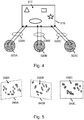
- Fig. 2 shows a method 200 for enabling estimating gaze from a set of eye measurement points.
- the method 200 may correspond to an operation of the system of Fig. 1 . It will be appreciated, however, that the method 200 may also be performed in separation of the system 100, e.g., using a different system or device.
- the method 200 comprises, in a first step titled "OBTAINING MEASUREMENT DATA OF MULTIPLE USERS", obtaining 210 at least a first set of eye measurement points of a first user viewing the scene and a second set of eye measurement points of a second user viewing the scene.
- the first set of eye measurement points are obtained as coordinates in a first coordinate system
- the second set of eye measurement points are obtained as coordinates in a second coordinate system
- the first coordinate system and the second coordinate system have an unknown geometric relation.
- the method 200 further comprises, in a second step titled “MUTUALLY CALIBRATING MEASUREMENT DATA OF USERS”, mapping 220 the first set of eye measurement points and the second set of eye measurement points to a common coordinate system, said mapping comprising establishing similar coordinates in the common coordinate system for geometrically similar topologies of both sets of eye measurement points.
- the method 200 further comprises, in a third step titled “MATCHING MUTUALLY CALIBRATED MEASUREMENT DATA TO SCENE", calculating 230 a scene transformation for mapping the common coordinate system to a coordinate system associated with the scene, said calculating comprising matching eye measurement points from the common coordinate system to interest points of the scene.
- Fig. 3 shows a computer program product 250 comprising instructions 240 for causing a processor system to perform the method of Fig. 2 .
- Fig. 3 shows the computer program product 250 in the form of an optical or magnetic disk, the computer program product 250 may also be constituted by a semiconductor memory-based device or assume any other suitable form.
- the instructions 240 may be comprised in a non-transitory manner on the computer program product 250, e.g., in the form of as a series of machine readable physical marks and/or as a series of elements having different electrical, e.g., magnetic, or optical properties or values.
- Fig. 4 illustrates a first user 020A, a second user 020B and a third user 020C viewing, i.e., gazing 030A-030C at, a same scene 010.
- the scene may be, e.g., a physical scene as presented in a shopping window, or a virtual scene as provided by content displayed on a computer screen.
- Fig. 4 shows the users 020A-020C viewing the scene 010 simultaneously, i.e., at a same time, the users 020A-020C may also view the same scene at different times, or view different instances of the same scene 010, e.g., at different locations, as displayed on different display devices, etc.
- the scene is shown to comprise a plurality of interest points 012, with the interest points 012 being schematically indicated in Fig. 1 as different geometrical shapes.
- interest points constitute points in the scene which are expected to draw a user's attention.
- the user's gaze may be expected to be drawn to a product which is shown most prominently in the shopping window.
- the interest points 012 may be known to the system in the form of coordinates defined in a coordinate system associated with the scene.
- Fig. 5 shows different sets of eye measurement points 050A-050C obtained from the different users of Fig. 4 , namely a first set of eye measurement points 050A of the first user, a second set of eye measurement points 050B of the second user, and a third set of eye measurement points 050C of the third user.
- Each set of eye measurement points 050A-050C represents measured quantities of the respective user which are indicative of the gaze pattern of the respective user when viewing the scene. It can be seen that the three sets of eye measurement points have locally similar geometric topologies. However, there also exist individual outliers in all three sets of eye measurement points, being indicative of one or more unique gaze points of a respective user.
- Each set of eye measurement points 050A-050C is defined as coordinates in a respective coordinate system 040A-040C, with the geometric relation between the coordinate systems being unknown.
- the coordinate systems 040A-040C differ due to the measurement data not being calibrated and thereby constituting 'raw' measurement data.
- Fig. 5 illustrates this difference by showing planes 040A-040C which represent the respective coordinate systems being mutually misaligned.
- Fig. 6 illustrates a result of the different sets of eye measurement points having been mapped to a common coordinate system 040X, namely by showing a combined set of eye measurement points 050X in the common coordinate system 040X.
- Said mapping may be performed in various ways based on the constraint that similar coordinates in the common coordinate system 040X are to be established for geometrically similar topologies of the different sets of eye measurement points. Such geometrically similar topologies may be explicitly identified. Alternatively, the mapping may involve an optimization which uses a cost function which has a relatively low cost when geometrically similar topologies of the different sets of eye measurement points are mapped to similar coordinates in the common coordinate system 040X.
- the mapping may be based on a so-termed K-closest point method.
- P u p 1 u , p 2 u , p 3 u , ... , p un u
- P u p 1 u , p 2 u , p 3 u , ... , p un u
- the set of eye measurement points of user u with un being typically different for each user.
- the method solves: where: where N ( p , , k ) is the k th closest point from to p .
- N ( p , , k ) is the k th closest point from to p .
- N p , , k
- ⁇ ⁇ ⁇ 1, ⁇ 2 .... ⁇ M ⁇ is the corresponding set of mappings. Note that the method tries to mutually map all sets of eye measurement points simultaneously.
- the method can also be applied iteratively.
- the method maps the set of eye measurement points of the first user to the common coordinate system using any mapping.
- the method finds the single mapping which maps the set of eye measurement points of a single user to the common coordinate system.
- An optimization method such as gradient descent may be employed to find the best set of mappings which minimizes the cost function. Note that other complex optimization methods may be applied to obtain the set of mappings.
- Another example of such a mapping involves the use of a mixture model.
- This mixture model models the already mapped sets of eye measurement points by a Gaussian mixture and finds a single mapping which, when applied on the set of eye measurement points of a new user, maximizes the probability density function of the these mapped eye measurement points.
- the method works in an iterative manner.
- P S are the already S mapped sets of eye measurement points of S users.
- K is the number of model components
- ⁇ k is the mixing coefficient of the kth Gaussian component (p
- ⁇ u(P u ) represents the mutually calibrated eye measurement points of user u, i.e., the eye measurement points after being mapped to the common coordinate system.
- mapping the set of eye measurements of the first user since there is only one set of eye measurements, any mapping may be used.
- the abovementioned steps can be applied for the second user on.
- An optimization method such as gradient descent may be employed to find the best mapping which maximizes the above optimization functions (3) and (4). Note that other complex optimization methods can be applied to obtain the mapping.
- Fig. 6 shows the different sets of eye measurement points of Fig. 5 all being mapped to a common coordinate system 040X such that geometrically similar topologies of the different sets of eye measurement points have similar coordinates in the common coordinate system, i.e., their main geometric topologies overlap.
- the mapping of the different sets of eye measurement points to the common coordinate system 040X may comprise a linear coordinate transformation.
- Fig. 6 further illustrates a scene transformation 300 being calculated which maps the common coordinate system 040X to a coordinate system associated with the scene 010, namely by matching eye measurement points 050X from the common coordinate system to interest points 012 of the scene.
- a set of gaze points 060X is obtained which represent the eye measurement points 050X being mapped to the coordinate system of the scene 010 and thereby being calibrated with respect to the scene 010. It can be seen that the gaze points substantially follow the interest points 012 of the scene, but that also deviations from the interest points 012 exist.
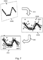
- Fig. 7 illustrates a set of gaze points being estimated of a further user viewing the scene based on a further set of eye measurement points of the further user being mapped to the common coordinate system.
- the input may be arranged for obtaining a further set of eye measurement points 050D of a further user viewing the scene 010.
- the further set of eye measurement points 050D may be defined as coordinates in a further coordinate system 040D, with the geometric relation between the further coordinate system 040D and the common coordinate system 040X not being known.
- the processing subsystem may be configured for mapping 310 the further set of eye measurement points 050D to the common coordinate system 040X in a similar manner as explained with reference to Fig.
- a further set of mapped eye measurement points 050Y may be obtained (shown in black to differentiate these from the set of mapped eye measurement points 050X), being defined by coordinates in the common coordinate system 040X.
- the processing subsystem may be further configured for estimating a set of gaze points 060Y of the further user by applying the scene transformation 300 to the further set of mapped eye measurement points 050Y.
- a set of gaze points 060Y may be obtained (shown in black to differentiate these from the set of gaze points 060X) which represent the further eye measurement points 050Y being mapped to the coordinate system of the scene 010 and thereby being calibrated with respect to the scene 010.
- the different sets of mapped eye measurement points may be combined to obtain a single set of reference points 050X.
- Such combining may involve applying a statistical filter to the different sets of eye measurement points.
- a further set of eye measurement points of a further user i.e., a new user, may be mapped to the common coordinate system 040X by matching geometrically similar topologies between the further set of eye measurement points and the set of reference points.
- the further set of mapped eye measurement points 050Y may be included in the set of reference points 050X so as to iteratively buildup the set of reference points.
- the scene transformation 300 may be re-calculated, i.e., updated, after including such a further set of mapped eye measurement points 050Y.
- the processing subsystem may further be configured for identifying a difference between the set of gaze points 060Y of a further user and a reference set of gaze points 060X which is associated with the set of reference points 050X.
- a difference may involve a difference in temporal order of gazing at same or similar parts of the scene 010, or a difference in the parts of the scene at which the gazing is directed.
- the measurement data, or auxiliary data needs to be indicative of this temporal order, e.g., by being sorted in accordance with time or by comprising a timestamp for each measurement point.
- mapping of the first set of eye measurement points and the second set of eye measurement points to a common coordinate system may further be based on temporal information provided by each set of measurement points.
- a gaze pattern may have a spatial topology but may also be indicative of an order or timing between the different gaze points, i.e., represent a temporal pattern.
- a time stamp may be provided with each eye measurement point which allows such a temporal pattern to be determined. Similarities or differences between these temporal patterns may be used in the mutual calibration.
- different users might exhibit similar temporal sub-patterns, i.e. they may view certain regions in the same order. These sub-patterns may be learnt and subsequently used to improve the mutual calibration.
- the invention may be advantageously used to auto-calibrate gaze estimators in an un-calibrated setup. Based on the observation that humans produce similar gaze patterns when looking at a stimulus, the mutually calibrated eye measurement points of several individuals and subsequent applying of the scene transformation may be used to estimate the gaze points for new viewers without active calibration.
- eye measurement points represent un-calibrated measurements from which a set of gaze points may be calculated, i.e., by calibration.
- the eye measurement points may represent changes in the user's eyes when viewing the scene. Such changes may be captured by a sensor (e.g. visual RGB camera or visual infrared camera).
- An eye measurement may be expressed as a scalar or a vector which may represent a state of the eye at a particular time. The measurement may contain information (features) which might be indicative of the eye gaze direction.
- An eye measurement point may be considered as a point representing the eye measurement in a coordinate system. Specific examples may be:
- any reference signs placed between parentheses shall not be construed as limiting the claim.
- Use of the verb "comprise” and its conjugations does not exclude the presence of elements or steps other than those stated in a claim.
- the article "a” or “an” preceding an element does not exclude the presence of a plurality of such elements.
- the invention may be implemented by means of hardware comprising several distinct elements, and by means of a suitably programmed computer. In the device claim enumerating several means, several of these means may be embodied by one and the same item of hardware. The mere fact that certain measures are recited in mutually different dependent claims does not indicate that a combination of these measures cannot be used to advantage.
Landscapes
- Engineering & Computer Science (AREA)
- Physics & Mathematics (AREA)
- Theoretical Computer Science (AREA)
- General Physics & Mathematics (AREA)
- General Engineering & Computer Science (AREA)
- Life Sciences & Earth Sciences (AREA)
- Data Mining & Analysis (AREA)
- Health & Medical Sciences (AREA)
- Human Computer Interaction (AREA)
- Mathematical Physics (AREA)
- Computational Mathematics (AREA)
- Mathematical Analysis (AREA)
- Mathematical Optimization (AREA)
- Pure & Applied Mathematics (AREA)
- Databases & Information Systems (AREA)
- Heart & Thoracic Surgery (AREA)
- Probability & Statistics with Applications (AREA)
- Software Systems (AREA)
- Operations Research (AREA)
- Evolutionary Biology (AREA)
- Bioinformatics & Computational Biology (AREA)
- Bioinformatics & Cheminformatics (AREA)
- Biophysics (AREA)
- Ophthalmology & Optometry (AREA)
- Biomedical Technology (AREA)
- Algebra (AREA)
- Medical Informatics (AREA)
- Molecular Biology (AREA)
- Surgery (AREA)
- Animal Behavior & Ethology (AREA)
- General Health & Medical Sciences (AREA)
- Public Health (AREA)
- Veterinary Medicine (AREA)
- Eye Examination Apparatus (AREA)
- User Interface Of Digital Computer (AREA)
Description
- The invention relates to a system and a method for enabling estimating gaze from a set of un-calibrated eye measurement points.
- The invention further relates to a computer program product comprising instructions for causing a processing subsystem to perform the method.
- Gaze estimation refers to the process of determining where a person is looking at in a predefined plane, i.e., a gaze plane. Such a gaze plane may be associated with a scene, such as, e.g., a physical scene as presented in a shopping window, or a virtual scene as provided by content displayed on a computer screen. Here, the points at which a person gazes at in the scene are referred to as gaze points. Gaze estimation is increasingly important for many applications such as human-computer interaction, marketing and advertisement, and human behavior analysis.
- Gaze estimation methods generally involve calibration. The calibration may be camera-based (estimating the camera parameters), geometric calibration (estimating the relations between the scene components like the camera, the gaze plane, and the user), or personal calibration (determining the angle between visual and optical axes). An extensive overview of the different approaches of gaze estimation and their calibration can be found in " In the Eye of the Beholder: A Survey of Models for Eyes and Gaze" by D.W Hansen et al., IEEE Transactions on Pattern Analysis and Machine Intelligence, Vol. 32, Issue 3, p. 478-500, 2010.
- During calibration, users are usually asked to fixate their gaze on certain points in a scene while images of their eyes are captured. This procedure is cumbersome and sometimes impractical. For example, when tracking costumer's attention in shops, estimating the gaze points or regions should be done passively, i.e., without the user having to actively take part in a calibration.
- It is known to use statistical data of eye movement measurements to enable such passive gaze estimation. For example,
US 7,657,062 B2 provides a calibration apparatus for automatically self-calibrating a set of eye tracking measurements to a reference space, said apparatus comprising: a tracking device capable of capturing a plurality of eye gaze measurements, representing a plurality of eye gaze positions; a statistical analyzer for determining a statistical distribution of said plurality of eye gaze measurements; a data storage device for storing a predetermined set of statistics data of eye movement measurements; a statistical data comparison component for comparing said statistical distribution data of said plurality of eye gaze measurements with said stored predetermined set of statistical data of eye movement measurements; and a calibration data generating component for generating a calibration data depending upon a result of said comparison. - Hence,
US 7,657,062 B2 uses statistical distribution data of which the relation to the reference space is known to calibrate the eye gaze measurements of a user. It is mentioned that the predetermined statistics may take two forms. Firstly, a set of statistics may be taken for a plurality of persons in order to obtain an "average" statistical information for human users, describing the eye movement patterns of a notional average person. Such statistics are not specific to any one individual person, but may represent a notional average person based upon an average of a test sample comprising a plurality of persons.Fig. 6 ofUS 7,657,062 B2 shows that the notional average person gazes straight ahead with the highest probability. Secondly, statistics may be derived for measurements taken from just one individual person. In this case, the individual person may have their own particular quirks and idiosyncrasies. -
WO 2013/059940 A1 describes a method for automating a gaze tracking system calibration based on display content and/or user actions that are likely to attract the subject's gaze. The method involves obtaining gaze data, obtaining at least one key point corresponding to a portion of media content being displayed, linking the gaze data to the at least one key point, and generating one or more calibration parameters by comparing gaze data with associated ones of the at least one key point - Disadvantageously,
US 7,657,062 B2 andWO 2013/059940 A1 each provide a relatively inaccurate estimation of the gaze of a user viewing a scene. - One of the objects of the invention is to obtain a system or method which enables the gaze of a user viewing a scene to be more accurately estimated.
- The following aspects of the invention are based on the insight that gaze patterns between different users are similar for a same scene. Here, the term 'gaze pattern' refers to the spatial distribution of gaze points with respect to the scene. As such, the eye measurement points of a user viewing a scene can be calibrated to the eye measurement points of another user viewing, or having viewed, the same scene. Hence, users do not need to actively participate in the calibration procedure.
- A first aspect of the invention provides a system for enabling estimating gaze of different users with respect to a scene from eye measurement points which represent un-calibrated eye measurements of the users viewing the scene, the system comprising:
- an input for obtaining at least a first set of eye measurement points of a first user viewing the scene and a second set of eye measurement points of a second user viewing the scene, the first set of eye measurement points being obtained as coordinates in a first coordinate system, the second set of eye measurement points being obtained as coordinates in a second coordinate system, the first coordinate system and the second coordinate system having an unknown geometric relation;
- a processing subsystem configured for:
- i) mutually calibrating the first set of eye measurement points and the second set of eye measurement points by mapping said points to a common coordinate system, thereby obtaining a set of mapped eye measurement points, said mapping comprising establishing a coordinate transformation which provides similar coordinates in the common coordinate system for geometrically similar topologies of both sets of eye measurement points; and
- ii) calculating a scene transformation for mapping the common coordinate system to a coordinate system associated with the scene, said calculating comprising matching eye measurement points from the set of mapped eye measurement points to interest points of the scene.
- A further aspect of the invention provides a method for enabling estimating gaze of different users with respect to a scene from eye measurement points which represent un-calibrated eye measurements of the users viewing the scene, the method comprising:
- obtaining at least a first set of eye measurement points of a first user viewing the scene and a second set of eye measurement points of a second user viewing the scene, the first set of eye measurement points being obtained as coordinates in a first coordinate system, the second set of eye measurement points being obtained as coordinates in a second coordinate system, the first coordinate system and the second coordinate system having an unknown geometric relation;
- mutually calibrating the first set of eye measurement points and the second set of eye measurement points by mapping said points to a common coordinate system, thereby obtaining a set of mapped eye measurement points, said mapping comprising establishing a coordinate transformation which provides similar coordinates in the common coordinate system for geometrically similar topologies of both sets of eye measurement points; and
- calculating a scene transformation for mapping the common coordinate system to a coordinate system associated with the scene, said calculating comprising matching eye measurement points from the set of mapped eye measurement points to interest points of the scene.
- A further aspect of the invention provides a computer program product comprising instructions for causing a processor system to perform the method.
- The above measures involve obtaining at least two sets of eye measurement points of different users viewing the same scene. Each set of eye measurement points is indicative of the gaze pattern of a respective user when the user is viewing the scene in that they represent un-calibrated measurements from which a set of gaze points may be calculated, i.e., by calibration. For example, the eye measurement points may represent changes in the user's eyes when viewing the scene. Such changes may be measured using, e.g., a video camera, a depth camera, infrared diodes, etc. As such, the eye measurement points may represent gaze directions, relative iris movements or changes in descriptors extracted from the eyes. However, the eye measurement points may also take any other suitable form.
- Both sets of eye measurement points are defined as coordinates in coordinate systems which have an unknown geometric relation. For example, the eye measurement points may be provided as Cartesian coordinates in planes having differently defined axes. As the geometric relation between the coordinate systems is not (entirely) known, both sets of eye measurement points are mutually un-calibrated in that the same coordinates in both coordinate systems may represent different measured quantities of both users, e.g., different gaze directions or different relative iris movements, and thus represent different gaze points with respect to the scene.
- A processing subsystem is provided for mapping the first set of eye measurement points and the second set of eye measurement points to a common coordinate system. In obtaining such a mapping, the processing subsystem ensures that similar coordinates in the common coordinate system are established for the geometrically similar topologies of both sets of eye measurement points. Here, the term 'topology', and in particular 'geometric topology', refers to the geometric relation between the eye measurement points, as indicated by, e.g., their relative position, their relative distance, etc. In other words, the geometric topology represents the spatial inter-relations and arrangement of eye measurement points.
- Moreover, the processing subsystem calculates a scene transformation for mapping the common coordinate system to a coordinate system associated with the scene. This calculation is performed on the basis of the processing subsystem matching eye measurement points from the common coordinate system to interest points of the scene. Here, the term 'interest point' refers to a point in the scene which is expected to draw a user's attention. For example, a linear transformation may be calculated which minimizes a distance measure being defined as a function of the distance between the eye measurement points and the interest points of the scene.
- The inventors have recognized that different users exhibit similar gaze patterns when viewing a same scene. This assumption is supported by the publication " Learning to predict where humans look" by Judd, K. Ehinger et al, IEEE International Conference on Computer Vision (ICCV), p. 2106-2113, 2009, in which the authors describe a database of (calibrated) eye tracking data which shows that the gaze patterns of previous users are predictive of those of new users viewing same scene. The invention makes use of the above recognition in that geometrically similar topologies in the eye measurement points of different users are assumed to represent a similar gaze pattern with respect to the scene. Accordingly, eye measurement points of different users may be mutually calibrated by mapping the eye measurement points to a common coordinate system in which the geometrically similar topologies match in coordinates, i.e., at least partially overlap. As a result, similar measured quantities of the different users, e.g., similar gaze directions or similar relative iris movements, are mapped to similar coordinates in the common coordinate system. Accordingly, after mapping, the eye measurement points of the different users are mutually calibrated.
- The above measures have the effect that a calibration between the eye measurement points of a particular user and the scene is obtained by mapping the user's eye measurement points together with those of at least one other user jointly to a common coordinate system. The scene transformation is then calculated based on eye measurement points which have been mapped to the common coordinate system.
- The inventors have recognized that this allows the eye measurement points of a single user to be more accurately calibrated since after said mapping, distinct patterns emerge in the common coordinate system which allow the mapping to the interest points to be more accurately calculated. Advantageously, the mapping of the eye measurement points of different users to a single coordinate system reduces the influence of individual outliers in the eye measurement points of each user. In contrast, when mapping the eye measurement points of each user individually to such interest points, it is not or less apparent which eye measurement points constitute outliers in the measurement, resulting in such individually calculated transformations to be less accurate. In this respect, it is noted that
US 7,657,062 B2 does not mutually calibrate eye measurement points relating to the viewing of a same scene but rather makes use of non-scene specific statistical data. Disadvantageously,US 7,657,062 B2 obtains a less accurate calibration. - It is noted that the above measures enable estimating gaze from a set of eye measurement points of the first user or the second user, in that a set of gaze points can be obtained when applying the scene transformation to the set of eye measurement points after being mapped to the common coordinate system.
- Optionally,the input is arranged for obtaining a further set of eye measurement points of a further user viewing the scene, the further set of eye measurement points being obtained as coordinates in a coordinate system having an unknown geometric relation with the common coordinate system, and the processing subsystem is configured for estimating a set of gaze points from the further set of eye measurement points by:
- i) mapping the further set of eye measurement points to the common coordinate system based on said establishing of similar coordinates for geometrically similar topologies, thereby obtaining a further set of mapped eye measurement points; and
- ii) estimating the set of gaze points of the further user by applying the scene transformation to the further set of mapped eye measurement points
- Accordingly, the eye measurement points of each further user viewing the scene may be automatically mutually calibrated with respect to those of other users viewing the scene by mapping the eye measurement points to the common coordinate system. Here, the mapping makes use of the abovementioned recognition that geometrically similar topologies in the eye measurement points of different users are assumed to represent a similar gaze pattern with respect to the scene. The same scene transformation may then be used to estimate the set of gaze points from the further set of mapped eye measurement points. It is therefore not needed to calculate the scene transformation anew for each further individual user viewing the scene.
- It is noted that a same effect may be obtained by, instead of performing the above steps i) and ii), performing the following steps j) and jj):
- j) applying the scene transformation to mapped eye measurement points of the common coordinate system to obtain a reference set of gaze points; and
- jj) estimating the set of gaze points of the further user by mapping the further set of eye measurement points directly to the coordinate system of the scene based on said establishing of similar coordinates for geometrically similar topologies between the reference set of gaze points and the set of gaze points of the further user.
- Optionally, the processing subsystem is configured for combining the set of mapped eye measurement points and the further set of mapped eye measurement points to obtain a set of reference points, and wherein said mapping of the further set of eye measurement points to the common coordinate system is performed by the processing subsystem matching geometrically similar topologies between the further set of eye measurement points and the set of reference points.
- By combining the set of mapped eye measurement points and the further set of mapped eye measurement points in the common coordinate system, a set of reference points is obtained. Such combining enables the influence of individual outliers to be explicitly reduced, e.g., by omitting or flagging such outliers. Effectively, the set of reference points may represent an estimate of the common interest points of different users, which may then be mapped to the (actual) interest points in the scene. Advantageously, the set of gaze points may be more accurately estimated.
- Optionally, the processing subsystem is configured for combining the set of mapped eye measurement points and the further set of mapped eye measurement points by applying a statistical filter to both sets of eye measurement points. Statistical filters, such as rank-order filters, enable the individual outliers in the eye measurement points of different users to be effectively reduced.
- Optionally, the processing subsystem is configured for including the further set of mapped eye measurement points in the set of reference points so as to iteratively buildup the set of reference points. By including further sets of eye measurement points in the set of reference points, the influence of individual outliers may be further reduced.
- Optionally, the processing subsystem is configured for re-calculating the scene transformation after said including of the further set of mapped eye measurement points. By updating the scene transformation, the accuracy of the scene transformation may be improved since the influence of individual outliers may have been further reduced by the inclusion of the further set of mapped eye measurement points. Advantageously, the system may use the eye measurement points of new users viewing the scene to gradually provide a more accurate estimation of their gaze.
- Optionally, the processing subsystem is configured for identifying a difference between the set of gaze points of the further user and a reference set of gaze points which is obtained by applying the scene transformation to the set of reference points. Differences between the gaze points of users may be highly relevant. For example, when viewing a shopping window, such differences may reflect individual preferences of users. By identifying such differences in the gaze points, the individual preferences are made visible. These may be used to later on dynamically customize the scene to each user.
- Optionally, the difference comprises at least one of: a difference in temporal order of gazing at same or similar parts of the scene, and a difference in the parts of the scene at which the gazing is directed. The order in which a user gazes at same or similar parts of the scene may reflect their individual preferences, as does the difference in the parts of the scene at which the user's gazing is directed.
- Optionally, the first set of eye measurement points and the second set of eye measurement points are obtained from users viewing different instances of the scene. The system thus combines the measurement data of users viewing different instances of the scene rather than viewing the same instance of the scene at different times. Advantageously, if there exist such different instances of a scene, the measurement data obtained at said scenes may be combined since the users are nevertheless expected to exhibit similar gaze patterns with respect to the scenes.
- Optionally, the different instances of the scene comprise at least one of: the scene at different locations, a display of the scene provided by different display devices, different types of physical display of the scene. Advantageously, the measurement data across different locations, different display devices or different types of physical display of the scene may be combined. Here, the term 'different types of physical display' refers to the scenes being displayed using different physical principles, e.g., using printed paper vs. using a digital screen.
- Optionally, the system further comprises a first eye measurement subsystem for obtaining the first set of eye measurement points of the first user viewing a first instance of the scene, and a second eye measurement subsystem for obtaining the second set of eye measurement points of the second user viewing a second instance of the scene, the first instance being different from the second instance. As a consequence of relating to different instances of the scene, the eye measurement subsystems are located at different locations, and/or are differently arranged so as to obtain the measurements with respect to the scene provided by different display devices, and/or provided by different types of physical display of the scene.
- Optionally, the input is arranged for obtaining an image of the scene, and the processing subsystem is configured for using a saliency detection technique to detect saliency points in the image so as to determine the interest points of the scene. By obtaining an image of the scene and detecting saliency points in the scene, it is not needed to manually annotate or otherwise determine the interest points of the scene.
- Optionally, the mapping of the first set of eye measurement points and the second set of eye measurement points to the common coordinate system comprises a linear coordinate transformation. A linear coordinate transformation is well suited for mapping the eye measurement points to a common coordinate system in which the geometrically similar topologies match in coordinates, i.e., at least partially overlap, while still allowing for individual differences in the eye measurement points. For example, the transformation may comprise translation, rotation, shearing and scaling.
- Optionally, each set of eye measurement points is constituted by a measurement of one of the group of: a gaze direction, an iris movement and a position of part of the eyes. The system may use various types of measurement data, including but not limited to measurement data of the aforementioned types.
- In summary, the invention enables estimating gaze from a set of eye measurement points which are indicative of a gaze pattern of a user viewing a scene. Herein, use is made of the insight that gaze patterns of different users are similar for a same scene. The invention involves obtaining different sets of eye measurement points from different users viewing the same scene. The different sets of eye measurement points are mapped to a common coordinate system, and thereby mutually calibrated, based on the assumption that geometrically similar topologies between the different sets of eye measurement points are to be mapped to similar coordinates in the common coordinate system as they represent a similar or same gaze pattern. A scene transformation for mapping the common coordinate system to a coordinate system associated with the scene can be calculated by matching eye measurement points from the common coordinate system to interest points of the scene. The scene transformation is thereby calculated more accurately than individually calculated scene transformations, thereby providing a more accurate estimate of the gaze points.
- It will be appreciated by those skilled in the art that two or more of the above-mentioned embodiments, implementations, and/or optional aspects of the invention may be combined in any way deemed useful.
- The invention is defined in the independent claims. Advantageous embodiments are defined in the dependent claims.
- These and other aspects of the invention are apparent from and will be elucidated with reference to the embodiments described hereinafter. In the drawings,
-
Fig. 1 shows a system in accordance with the present invention, the system being arranged for enabling estimating gaze from at least two set of eye measurement points of respective users viewing a same scene; -
Fig. 2 shows a method in accordance with the present invention; -
Fig. 3 shows a computer program product comprising instructions for causing a processor system to perform the method; -
Fig. 4 illustrates different users viewing a same scene, with the scene comprising a plurality of interest points; -
Fig. 5 shows different sets of eye measurement points as obtained from the different users, each set of eye measurement points being defined in a coordinate system, with the geometric relation between the coordinate systems being unknown; -
Fig. 6 illustrates a result of the different sets of eye measurement points having been mapped to a common coordinate system, and eye measurement points from the common coordinate systems having been mapped to interest points of the scene;and -
Fig. 7 illustrates a set of gaze points of a further user viewing the scene being estimated based on a further set of eye measurement points of the further user being mapped to the common coordinate system. - It should be noted that items which have the same reference numbers in different Figures, have the same structural features and the same functions, or are the same signals. Where the function and/or structure of such an item has been explained, there is no necessity for repeated explanation thereof in the detailed description.
-
Fig. 1 shows asystem 100 comprising aninput 120 for obtaining at least a first set ofeye measurement points 050A of a first user viewing a scene and a second set of eye measurement points 050B of a second user viewing the scene. Here, each set of eye measurement points is indicative of a gaze pattern of the respective user when viewing the scene. Such sets of eye measurement points may be obtained in various ways. For example, thesystem 100 may be connected to a measurement system (not shown inFig. 1 ) which measures, in real-time when a user views the scene, a change in the user's relative iris movement, a change in the position of the user's eyes, etc. Alternatively or additionally,such measurement data input 120 may constitute or be part of, e.g., a network interface or a storage interface. - The first set of eye measurement points 050A are obtained as coordinates in a first coordinate system and the second set of eye measurement points 050B are obtained as coordinates in a second coordinate system. The first coordinate system and the second coordinate system have an unknown geometric relation in that it is not known how a coordinate in the first coordinate system relates to the same coordinate in the second coordinate system, i.e., whether or not it concerns a same measured quantity, and in case of the latter, what the difference in measured quantity is.
- The
system 100 further comprises aprocessing subsystem 140. Theprocessing subsystem 140 is shown to communicate with theinput 120 via an exchange ofmessages 122, thereby enabling theprocessing subsystem 140 to access the first set ofeye measurement points 050A and the first second of eye measurement points 050B. Theprocessing subsystem 140 is configured to perform the following actions during operation of thesystem 100. Firstly, theprocessing subsystem 140 maps the first set ofeye measurement points 050A and the second set of eye measurement points 050B to a common coordinate system, the mapping being based on similar coordinates being established in the common coordinate system for geometrically similar topologies of both sets of eye measurement points. Theprocessing subsystem 140 further calculates a scene transformation for mapping the common coordinate system to a coordinate system associated with the scene, the calculating involving matching eye measurement points from the common coordinate system to interest points of the scene. - The operation of the
system 100, including various optional aspects of thesystem 100, will be further explained with reference toFigs. 4 to 7 . -
Fig. 1 shows such an optional aspect of thesystem 100 in that thesystem 100 comprises anoutput 160 for outputting data such as a set of gaze points 060X. The set ofgaze points 060X which may be estimated by theprocessing subsystem 140 by mapping a set of eye measurement points, such as those of the first user or the second user, to the common coordinate system and subsequently applying the scene transformation to said set of mapped eye measurement points, thereby obtaining a set of gaze points defined in the coordinate system associated with the scene. To output such data, theprocessing subsystem 140 is shown to communicate with theoutput 160 via an exchange ofmessages 142. Theoutput 160 may constitute, or be part of, e.g., a network interface, a storage interface, a display output, etc. - The
output 160 may also output other data such as adifference 162 between a set of gaze points of a further user and a reference set of gaze points. This aspect of the invention will be further explained with reference toFigs. 4 to 7 . -
Fig. 1 shows a further optional aspect of thesystem 100 in that theinput 120 is shown to be arranged for obtaining animage 015 of the scene, with theprocessing subsystem 140 being configured for using a saliency detection technique to detect saliency points in the image so as to determine the interest points of the scene. It will be appreciated that the interest points may also be determined in various other ways as known per se in the art of eye gaze estimation. For example, instead of obtaining animage 015, theinput 120 may obtain interest point data representing coordinates of the interest points in the coordinate system associated with the scene. Such coordinates may be manually determined, e.g., manually annotated, or determined automatically, e.g., using the aforementioned saliency detection. -
Fig. 2 shows amethod 200 for enabling estimating gaze from a set of eye measurement points. Themethod 200 may correspond to an operation of the system ofFig. 1 . It will be appreciated, however, that themethod 200 may also be performed in separation of thesystem 100, e.g., using a different system or device. - The
method 200 comprises, in a first step titled "OBTAINING MEASUREMENT DATA OF MULTIPLE USERS", obtaining 210 at least a first set of eye measurement points of a first user viewing the scene and a second set of eye measurement points of a second user viewing the scene. Here, the first set of eye measurement points are obtained as coordinates in a first coordinate system, the second set of eye measurement points are obtained as coordinates in a second coordinate system, and the first coordinate system and the second coordinate system have an unknown geometric relation. Themethod 200 further comprises, in a second step titled "MUTUALLY CALIBRATING MEASUREMENT DATA OF USERS",mapping 220 the first set of eye measurement points and the second set of eye measurement points to a common coordinate system, said mapping comprising establishing similar coordinates in the common coordinate system for geometrically similar topologies of both sets of eye measurement points. Themethod 200 further comprises, in a third step titled "MATCHING MUTUALLY CALIBRATED MEASUREMENT DATA TO SCENE", calculating 230 a scene transformation for mapping the common coordinate system to a coordinate system associated with the scene, said calculating comprising matching eye measurement points from the common coordinate system to interest points of the scene. -
Fig. 3 shows acomputer program product 250 comprisinginstructions 240 for causing a processor system to perform the method ofFig. 2 . AlthoughFig. 3 shows thecomputer program product 250 in the form of an optical or magnetic disk, thecomputer program product 250 may also be constituted by a semiconductor memory-based device or assume any other suitable form. Theinstructions 240 may be comprised in a non-transitory manner on thecomputer program product 250, e.g., in the form of as a series of machine readable physical marks and/or as a series of elements having different electrical, e.g., magnetic, or optical properties or values. - The operation of the system of
Fig. 1 , the method ofFig. 2 , and various optional aspects of the system and method, may be further explained as follows. It is noted that here, such operation is explained based on measurement data of three different users viewing the scene. It will be appreciated that the explanation equally holds for the use of measurement data of two different users viewing the scene. -
Fig. 4 illustrates afirst user 020A, asecond user 020B and athird user 020C viewing, i.e., gazing 030A-030C at, asame scene 010. The scene may be, e.g., a physical scene as presented in a shopping window, or a virtual scene as provided by content displayed on a computer screen. AlthoughFig. 4 shows theusers 020A-020C viewing thescene 010 simultaneously, i.e., at a same time, theusers 020A-020C may also view the same scene at different times, or view different instances of thesame scene 010, e.g., at different locations, as displayed on different display devices, etc. - The scene is shown to comprise a plurality of
interest points 012, with the interest points 012 being schematically indicated inFig. 1 as different geometrical shapes. Such interest points constitute points in the scene which are expected to draw a user's attention. For example, in a shopping window, the user's gaze may be expected to be drawn to a product which is shown most prominently in the shopping window. The interest points 012 may be known to the system in the form of coordinates defined in a coordinate system associated with the scene. -
Fig. 5 shows different sets of eye measurement points 050A-050C obtained from the different users ofFig. 4 , namely a first set ofeye measurement points 050A of the first user, a second set of eye measurement points 050B of the second user, and a third set of eye measurement points 050C of the third user. Each set of eye measurement points 050A-050C represents measured quantities of the respective user which are indicative of the gaze pattern of the respective user when viewing the scene. It can be seen that the three sets of eye measurement points have locally similar geometric topologies. However, there also exist individual outliers in all three sets of eye measurement points, being indicative of one or more unique gaze points of a respective user. - Each set of eye measurement points 050A-050C is defined as coordinates in a respective coordinate
system 040A-040C, with the geometric relation between the coordinate systems being unknown. Typically, the coordinatesystems 040A-040C differ due to the measurement data not being calibrated and thereby constituting 'raw' measurement data.Fig. 5 illustrates this difference by showingplanes 040A-040C which represent the respective coordinate systems being mutually misaligned. -
Fig. 6 illustrates a result of the different sets of eye measurement points having been mapped to a common coordinatesystem 040X, namely by showing a combined set of eye measurement points 050X in the common coordinatesystem 040X. - Said mapping may be performed in various ways based on the constraint that similar coordinates in the common coordinate
system 040X are to be established for geometrically similar topologies of the different sets of eye measurement points. Such geometrically similar topologies may be explicitly identified. Alternatively, the mapping may involve an optimization which uses a cost function which has a relatively low cost when geometrically similar topologies of the different sets of eye measurement points are mapped to similar coordinates in the common coordinatesystem 040X. - For example, the mapping may be based on a so-termed K-closest point method. Here and in the following, let


- The K-closest point method involves finding a set of mappings
Φ = {φ 1,φ 2 ....φ M} which (after applied onresulting

 . In other words, the method solves:

 , k) is the kth closest point fromto p. Here,represents the mutually calibrated eye measurement points of all users, i.e., the eye measurement points after being mapped to the common coordinate system, and
Φ = {φ 1,φ 2 ....φ M} is the corresponding set of mappings. Note that the method tries to mutually map all sets of eye measurement points simultaneously. - The method can also be applied iteratively. In such a case, the method maps the set of eye measurement points of the first user to the common coordinate system using any mapping. From the second user on, the method finds the single mapping which maps the set of eye measurement points of a single user to the common coordinate system. An optimization method such as gradient descent may be employed to find the best set of mappings which minimizes the cost function. Note that other complex optimization methods may be applied to obtain the set of mappings.
- Another example of such a mapping involves the use of a mixture model. This mixture model models the already mapped sets of eye measurement points by a Gaussian mixture and finds a single mapping which, when applied on the set of eye measurement points of a new user, maximizes the probability density function of the these mapped eye measurement points. The method works in an iterative manner.
- Consider
 as a Gaussian mixture. Let


- K is the number of model components, πk is the mixing coefficient of the kth Gaussian component(p| µk, Σk) with µk mean and ∑k covariance matrix. Here,

Φ u(Pu) represents the mutually calibrated eye measurement points of user u, i.e., the eye measurement points after being mapped to the common coordinate system. - For mapping the set of eye measurements of the first user, since there is only one set of eye measurements, any mapping may be used. The abovementioned steps can be applied for the second user on. An optimization method such as gradient descent may be employed to find the best mapping which maximizes the above optimization functions (3) and (4). Note that other complex optimization methods can be applied to obtain the mapping.
- As a result,
Fig. 6 shows the different sets of eye measurement points ofFig. 5 all being mapped to a common coordinatesystem 040X such that geometrically similar topologies of the different sets of eye measurement points have similar coordinates in the common coordinate system, i.e., their main geometric topologies overlap. In general, the mapping of the different sets of eye measurement points to the common coordinatesystem 040X may comprise a linear coordinate transformation. -
Fig. 6 further illustrates ascene transformation 300 being calculated which maps the common coordinatesystem 040X to a coordinate system associated with thescene 010, namely by matching eye measurement points 050X from the common coordinate system to interestpoints 012 of the scene. As a result, a set ofgaze points 060X is obtained which represent theeye measurement points 050X being mapped to the coordinate system of thescene 010 and thereby being calibrated with respect to thescene 010. It can be seen that the gaze points substantially follow the interest points 012 of the scene, but that also deviations from the interest points 012 exist. -
Fig. 7 illustrates a set of gaze points being estimated of a further user viewing the scene based on a further set of eye measurement points of the further user being mapped to the common coordinate system. This example is associated with an optional aspect of the invention, in that the input may be arranged for obtaining a further set of eye measurement points 050D of a further user viewing thescene 010. The further set of eye measurement points 050D may be defined as coordinates in a further coordinatesystem 040D, with the geometric relation between the further coordinatesystem 040D and the common coordinatesystem 040X not being known. The processing subsystem may be configured for mapping 310 the further set of eye measurement points 050D to the common coordinatesystem 040X in a similar manner as explained with reference toFig. 6 , namely based on similar coordinates being established for geometrically similar topologies. Accordingly, a further set of mapped eye measurement points 050Y may be obtained (shown in black to differentiate these from the set of mapped eye measurement points 050X), being defined by coordinates in the common coordinatesystem 040X. The processing subsystem may be further configured for estimating a set ofgaze points 060Y of the further user by applying thescene transformation 300 to the further set of mapped eye measurement points 050Y. As a result, a set ofgaze points 060Y may be obtained (shown in black to differentiate these from the set of gaze points 060X) which represent the furthereye measurement points 050Y being mapped to the coordinate system of thescene 010 and thereby being calibrated with respect to thescene 010. - It will be appreciated that the different sets of mapped eye measurement points, i.e., after being mapped to the common coordinate system, may be combined to obtain a single set of
reference points 050X. Such combining may involve applying a statistical filter to the different sets of eye measurement points. Having established such a set of reference points, e.g., constituted by all previously mapped eye measurement points, a further set of eye measurement points of a further user, i.e., a new user, may be mapped to the common coordinatesystem 040X by matching geometrically similar topologies between the further set of eye measurement points and the set of reference points. After being mapped to the common coordinatesystem 040X, the further set of mapped eye measurement points 050Y may be included in the set ofreference points 050X so as to iteratively buildup the set of reference points. In addition, thescene transformation 300 may be re-calculated, i.e., updated, after including such a further set of mapped eye measurement points 050Y. - The processing subsystem may further be configured for identifying a difference between the set of
gaze points 060Y of a further user and a reference set ofgaze points 060X which is associated with the set ofreference points 050X. Such a difference may involve a difference in temporal order of gazing at same or similar parts of thescene 010, or a difference in the parts of the scene at which the gazing is directed. In order to establish the former difference, the measurement data, or auxiliary data, needs to be indicative of this temporal order, e.g., by being sorted in accordance with time or by comprising a timestamp for each measurement point. - It will be appreciated that the mapping of the first set of eye measurement points and the second set of eye measurement points to a common coordinate system, i.e., the mutual calibration, may further be based on temporal information provided by each set of measurement points. A reason for this is that a gaze pattern may have a spatial topology but may also be indicative of an order or timing between the different gaze points, i.e., represent a temporal pattern. For example, a time stamp may be provided with each eye measurement point which allows such a temporal pattern to be determined. Similarities or differences between these temporal patterns may be used in the mutual calibration. For example, different users might exhibit similar temporal sub-patterns, i.e. they may view certain regions in the same order. These sub-patterns may be learnt and subsequently used to improve the mutual calibration.
- It will be further appreciated that the invention may be advantageously used to auto-calibrate gaze estimators in an un-calibrated setup. Based on the observation that humans produce similar gaze patterns when looking at a stimulus, the mutually calibrated eye measurement points of several individuals and subsequent applying of the scene transformation may be used to estimate the gaze points for new viewers without active calibration.
- It is noted that in general, eye measurement points represent un-calibrated measurements from which a set of gaze points may be calculated, i.e., by calibration. For example, the eye measurement points may represent changes in the user's eyes when viewing the scene. Such changes may be captured by a sensor (e.g. visual RGB camera or visual infrared camera). An eye measurement may be expressed as a scalar or a vector which may represent a state of the eye at a particular time. The measurement may contain information (features) which might be indicative of the eye gaze direction. An eye measurement point may be considered as a point representing the eye measurement in a coordinate system. Specific examples may be:
- 1. Relative movement of the pupil:
- a. The eye measurement may be a 3D vector representing changes of the position of the eye pupil in a 3D cartesian coordinate system. The origin (0, 0, 0) may be a fixed point. The eye pupil center may be detected using any (visual) sensor.
- b. The eye measurement may be a 3D vector representing changes of the position of the eye pupil in a 3D cylindrical coordinate system. The origin (0,0,0) may be the position of the eye pupil at time t0.
- 2. Intensity vector of an eye image: an image showing the eye may be cropped and resized to a (L,W) crop size. The eye measurement may be a vector of the size (L*W,1) which may contain the intensity values of the cropped image. The cropped image may be divided into a AxB grid and the intensity distribution (e.g. histogram) may be computed for each grid. An eye measurement may result from combining the grid-based distributions to into a single vector. Variations may be obtained by considering color values along with/instead of intensity values.
- It should be noted that the above-mentioned embodiments illustrate rather than limit the invention, and that those skilled in the art will be able to design many alternative embodiments.
- In the claims, any reference signs placed between parentheses shall not be construed as limiting the claim. Use of the verb "comprise" and its conjugations does not exclude the presence of elements or steps other than those stated in a claim. The article "a" or "an" preceding an element does not exclude the presence of a plurality of such elements. The invention may be implemented by means of hardware comprising several distinct elements, and by means of a suitably programmed computer. In the device claim enumerating several means, several of these means may be embodied by one and the same item of hardware. The mere fact that certain measures are recited in mutually different dependent claims does not indicate that a combination of these measures cannot be used to advantage.
Claims (15)
- A system (100) for enabling estimating gaze of different users with respect to a scene (010) from eye measurement points which represent un-calibrated eye measurements of the users viewing the scene from which a set of gaze points may be calculated by calibration, the system comprising:- an input (120) for obtaining at least a first set of eye measurement points (050A) of a first user (020A) viewing the scene (010) and a second set of eye measurement points (050B) of a second user (020B) viewing the scene (010), the first set of eye measurement points being obtained as coordinates in a first coordinate system (040A), the second set of eye measurement points being obtained as coordinates in a second coordinate system (040B), the first coordinate system and the second coordinate system having an unknown geometric relation;- a processing subsystem (140) configured for:i) mutually calibrating the first set of eye measurement points (050A) and the second set of eye measurement points (050B) by mapping said points to a common coordinate system (040X), thereby obtaining a set of mapped eye measurement points (050X), said mapping comprising optimizing a cost function which has a relatively low cost when geometrically similar topologies of the different sets of eye measurement points are mapped to similar coordinates in the common coordinate system; andii) calculating a scene transformation for mapping the common coordinate system (040X) to a coordinate system associated with the scene (010), said calculating comprising matching eye measurement points from the set of mapped eye measurement points (050X) to interest points (012) of the scene.
- The system (100) according to claim 1, wherein:- the input (120) is arranged for obtaining a further set of eye measurement points (050D) of a further user viewing the scene (010), the further set of eye measurement points being obtained as coordinates in a coordinate system (040D) having an unknown geometric relation with the common coordinate system (040X); and- the processing subsystem (140) is configured for estimating a set of gaze points (060Y) from the further set of eye measurement points by:i) mapping the further set of eye measurement points to the common coordinate system (040X) based on said establishing of similar coordinates for geometrically similar topologies between the further set of eye measurement points (050D) and the set of mapped eye measurement points (050X), thereby obtaining a further set of mapped eye measurement points (050Y); andii) estimating the set of gaze points (060Y) of the further user by applying the scene transformation to the further set of mapped eye measurement points (050Y).
- The system (100) according to claim 2, wherein the processing subsystem (140) is configured for combining the set of mapped eye measurement points (050X) and the further set of mapped eye measurement points (050Y) to obtain a set of reference points, and wherein said mapping of the further set of eye measurement points (050D) to the common coordinate system (040X) is performed by the processing subsystem matching geometrically similar topologies between the further set of eye measurement points (050D) and the set of reference points.
- The system (100) according to claim 3, wherein the processing subsystem (140) is configured for combining the set of mapped eye measurement points (050X) and the further set of mapped eye measurement points (050Y) by applying a statistical filter to both sets of eye measurement points.
- The system (100) according to claim 3 or 4, wherein the processing subsystem (140) is configured for including the further set of mapped eye measurement points (050Y) in the set of reference points so as to iteratively buildup the set of reference points.
- The system (100) according to claim 5, wherein the processing subsystem (140) is configured for re-calculating the scene transformation after said including of the further set of mapped eye measurement points (050Y).
- The system (100) according to any one of claims 3 to 6, wherein the processing subsystem (140) is configured for identifying a difference (162) between the set of gaze points (060Y) of the further user and a reference set of gaze points (060X) which is obtained by applying the scene transformation to the set of reference points.
- The system (100) according to claim 7, wherein the difference (162) comprises at least one of: a difference in temporal order of gazing at same or similar parts of the scene (010), and a difference in the parts of the scene at which the gazing is directed.
- The system (100) according to any one of claims 1 to 8, wherein the first set of eye measurement points (050A) and the second set of eye measurement points (050B) are obtained from users (020A, 020B) viewing different instances of the scene (010).
- The system (100) according to claim 9, wherein the different instances of the scene (010) comprise at least one of: the scene at different locations, a display of the scene provided by different display devices, different types of physical display of the scene.
- The system (100) according to any one of claims 1 to 10, wherein the input (120) is arranged for obtaining an image (015) of the scene (010), and wherein the processing subsystem (140) is configured for using a saliency detection technique to detect saliency points in the image so as to determine the interest points (012) of the scene.
- The system (100) according to any one of claims 1 to 11, wherein the mapping of the first set of eye measurement points (050A) and the second set of eye measurement points (050B) to the common coordinate system (040X) comprises a linear coordinate transformation.
- The system (100) according to any one of claims 1 to 12, wherein each set of eye measurement points (050A-050D) is constituted by a measurement of one of the group of: a gaze direction, an iris movement and a position of part of the eyes.
- Method (200) for enabling estimating gaze of different users with respect to a scene from eye measurement points which represent un-calibrated eye measurements of the users viewing the scene, the method comprising:- obtaining (210) at least a first set of eye measurement points of a first user viewing the scene and a second set of eye measurement points of a second user viewing the scene, the first set of eye measurement points being obtained as coordinates in a first coordinate system, the second set of eye measurement points being obtained as coordinates in a second coordinate system, the first coordinate system and the second coordinate system having an unknown geometric relation;- mutually calibrating (220) the first set of eye measurement points and the second set of eye measurement points by mapping said points to a common coordinate system, thereby obtaining a set of mapped eye measurement points, said mapping comprising optimizing a cost function which has a relatively low cost when geometrically similar topologies of the different sets of eye measurement points are mapped to similar coordinates in the common coordinate system; and- calculating (230) a scene transformation for mapping the common coordinate system to a coordinate system associated with the scene, said calculating comprising matching eye measurement points from the set of mapped eye measurement points to interest points of the scene.
- Computer program product (250) comprising instructions (240) for causing a processor system to perform the method according to claim 14.
Priority Applications (1)
| Application Number | Priority Date | Filing Date | Title |
|---|---|---|---|
| EP14805286.3A EP3074844B1 (en) | 2013-11-29 | 2014-11-28 | Estimating gaze from un-calibrated eye measurement points |
Applications Claiming Priority (3)
| Application Number | Priority Date | Filing Date | Title |
|---|---|---|---|
| EP13195179.0A EP2879018A1 (en) | 2013-11-29 | 2013-11-29 | Estimating gaze from un-calibrated eye measurement points |
| PCT/EP2014/076026 WO2015079054A1 (en) | 2013-11-29 | 2014-11-28 | Estimating gaze from un-calibrated eye measurement points |
| EP14805286.3A EP3074844B1 (en) | 2013-11-29 | 2014-11-28 | Estimating gaze from un-calibrated eye measurement points |
Publications (2)
| Publication Number | Publication Date |
|---|---|
| EP3074844A1 EP3074844A1 (en) | 2016-10-05 |
| EP3074844B1 true EP3074844B1 (en) | 2018-03-28 |
Family
ID=49680892
Family Applications (2)
| Application Number | Title | Priority Date | Filing Date |
|---|---|---|---|
| EP13195179.0A Withdrawn EP2879018A1 (en) | 2013-11-29 | 2013-11-29 | Estimating gaze from un-calibrated eye measurement points |
| EP14805286.3A Active EP3074844B1 (en) | 2013-11-29 | 2014-11-28 | Estimating gaze from un-calibrated eye measurement points |
Family Applications Before (1)
| Application Number | Title | Priority Date | Filing Date |
|---|---|---|---|
| EP13195179.0A Withdrawn EP2879018A1 (en) | 2013-11-29 | 2013-11-29 | Estimating gaze from un-calibrated eye measurement points |
Country Status (3)
| Country | Link |
|---|---|
| US (1) | US9924865B2 (en) |
| EP (2) | EP2879018A1 (en) |
| WO (1) | WO2015079054A1 (en) |
Families Citing this family (4)
| Publication number | Priority date | Publication date | Assignee | Title |
|---|---|---|---|---|
| US11579686B2 (en) | 2016-03-07 | 2023-02-14 | Apple Inc. | Method and device for carrying out eye gaze mapping |
| DE102016210288A1 (en) | 2016-06-10 | 2017-12-14 | Volkswagen Aktiengesellschaft | Eyetracker unit operating device and method for calibrating an eyetracker unit of an operating device |
| US10337675B2 (en) * | 2016-10-31 | 2019-07-02 | Clean Concept Llc | Insect control lighting device |
| CN108882186B (en) * | 2018-06-13 | 2022-05-17 | 孔祥溪 | Online and offline device characteristic data collection method based on advertisement transaction integration |
Family Cites Families (12)
| Publication number | Priority date | Publication date | Assignee | Title |
|---|---|---|---|---|
| JP2988178B2 (en) * | 1993-03-11 | 1999-12-06 | 日産自動車株式会社 | Gaze direction measuring device |
| US6359601B1 (en) * | 1993-09-14 | 2002-03-19 | Francis J. Maguire, Jr. | Method and apparatus for eye tracking |
| US6381339B1 (en) * | 1997-01-15 | 2002-04-30 | Winton Emery Brown | Image system evaluation method and apparatus using eye motion tracking |
| US6758563B2 (en) * | 1999-12-30 | 2004-07-06 | Nokia Corporation | Eye-gaze tracking |
| GB2412431B (en) * | 2004-03-25 | 2007-11-07 | Hewlett Packard Development Co | Self-calibration for an eye tracker |
| US20100295774A1 (en) * | 2009-05-19 | 2010-11-25 | Mirametrix Research Incorporated | Method for Automatic Mapping of Eye Tracker Data to Hypermedia Content |
| EP2632322A1 (en) * | 2010-10-29 | 2013-09-04 | IT-universitetet I København | Method of determining reflections of light |
| WO2013059940A1 (en) * | 2011-10-27 | 2013-05-02 | Tandemlaunch Technologies Inc. | System and method for calibrating eye gaze data |
| WO2013149966A1 (en) * | 2012-04-02 | 2013-10-10 | Thomson Licensing | Method for calibration free gaze tracking using low cost camera |
| GB201305726D0 (en) * | 2013-03-28 | 2013-05-15 | Eye Tracking Analysts Ltd | A method for calibration free eye tracking |
| KR20160038476A (en) * | 2014-09-30 | 2016-04-07 | 현대자동차주식회사 | Apparatus and Method for calibrating Gaze |
| WO2016077343A1 (en) * | 2014-11-10 | 2016-05-19 | Visionize Corp. | Methods and apparatus for vision enhancement |
-
2013
- 2013-11-29 EP EP13195179.0A patent/EP2879018A1/en not_active Withdrawn
-
2014
- 2014-11-28 US US15/100,228 patent/US9924865B2/en active Active
- 2014-11-28 WO PCT/EP2014/076026 patent/WO2015079054A1/en active Application Filing
- 2014-11-28 EP EP14805286.3A patent/EP3074844B1/en active Active
Also Published As
| Publication number | Publication date |
|---|---|
| US20170007118A1 (en) | 2017-01-12 |
| WO2015079054A1 (en) | 2015-06-04 |
| EP2879018A1 (en) | 2015-06-03 |
| US9924865B2 (en) | 2018-03-27 |
| EP3074844A1 (en) | 2016-10-05 |
Similar Documents
| Publication | Publication Date | Title |
|---|---|---|
| US11775056B2 (en) | System and method using machine learning for iris tracking, measurement, and simulation | |
| US11747898B2 (en) | Method and apparatus with gaze estimation | |
| US9164583B2 (en) | Method and apparatus for gaze point mapping | |
| Alnajar et al. | Calibration-free gaze estimation using human gaze patterns | |
| EP2856426B1 (en) | Body measurement | |
| CN110869938A (en) | Personnel identification system and method | |
| CN108985210A (en) | A kind of Eye-controlling focus method and system based on human eye geometrical characteristic | |
| EP3154407B1 (en) | A gaze estimation method and apparatus | |
| JP6822482B2 (en) | Line-of-sight estimation device, line-of-sight estimation method, and program recording medium | |
| EP3074844B1 (en) | Estimating gaze from un-calibrated eye measurement points | |
| WO2020032254A1 (en) | Attention target estimating device, and attention target estimating method | |
| Weiss et al. | Symmetric or not? A holistic approach to the measurement of fluctuating asymmetry from facial photographs | |
| US20230091536A1 (en) | Camera Placement Guidance | |
| CN110603508B (en) | Media content tracking | |
| JP6311461B2 (en) | Gaze analysis system and gaze analysis apparatus | |
| CN112613357B (en) | Face measurement method, device, electronic equipment and medium | |
| Marcialis et al. | A novel method for head pose estimation based on the “Vitruvian Man” | |
| Paletta et al. | A computer vision system for attention mapping in SLAM based 3D models | |
| Laco et al. | Depth in the visual attention modelling from the egocentric perspective of view | |
| Li et al. | Automatic detection and boundary estimation of the optic disk in retinal images using a model-based approach | |
| Bozomitu et al. | Pupil detection algorithm based on RANSAC procedure | |
| Wright et al. | Measuring inferred gaze direction to support analysis of people in a meeting | |
| US20230360350A1 (en) | Systems and methods for scaling using estimated facial features | |
| Wankhade et al. | A Review on Essential Resources Utilized for Face Recognition | |
| Qiao et al. | Depth data filtering for real-time head pose estimation with Kinect |
Legal Events
| Date | Code | Title | Description |
|---|---|---|---|
| PUAI | Public reference made under article 153(3) epc to a published international application that has entered the european phase |
Free format text: ORIGINAL CODE: 0009012 |
|
| 17P | Request for examination filed |
Effective date: 20160629 |
|
| AK | Designated contracting states |
Kind code of ref document: A1 Designated state(s): AL AT BE BG CH CY CZ DE DK EE ES FI FR GB GR HR HU IE IS IT LI LT LU LV MC MK MT NL NO PL PT RO RS SE SI SK SM TR |
|
| AX | Request for extension of the european patent |
Extension state: BA ME |
|
| DAX | Request for extension of the european patent (deleted) | ||
| GRAP | Despatch of communication of intention to grant a patent |
Free format text: ORIGINAL CODE: EPIDOSNIGR1 |
|
| RIC1 | Information provided on ipc code assigned before grant |
Ipc: G06F 17/18 20060101ALI20170919BHEP Ipc: A61B 3/113 20060101ALI20170919BHEP Ipc: G06F 3/01 20060101AFI20170919BHEP |
|
| INTG | Intention to grant announced |
Effective date: 20171011 |
|
| GRAS | Grant fee paid |
Free format text: ORIGINAL CODE: EPIDOSNIGR3 |
|
| GRAA | (expected) grant |
Free format text: ORIGINAL CODE: 0009210 |
|
| AK | Designated contracting states |
Kind code of ref document: B1 Designated state(s): AL AT BE BG CH CY CZ DE DK EE ES FI FR GB GR HR HU IE IS IT LI LT LU LV MC MK MT NL NO PL PT RO RS SE SI SK SM TR |
|
| REG | Reference to a national code |
Ref country code: GB Ref legal event code: FG4D |
|
| REG | Reference to a national code |
Ref country code: CH Ref legal event code: EP |
|
| REG | Reference to a national code |
Ref country code: AT Ref legal event code: REF Ref document number: 983991 Country of ref document: AT Kind code of ref document: T Effective date: 20180415 |
|
| REG | Reference to a national code |
Ref country code: IE Ref legal event code: FG4D |
|
| REG | Reference to a national code |
Ref country code: DE Ref legal event code: R096 Ref document number: 602014023083 Country of ref document: DE |
|
| REG | Reference to a national code |
Ref country code: NL Ref legal event code: FP |
|
| PG25 | Lapsed in a contracting state [announced via postgrant information from national office to epo] |
Ref country code: NO Free format text: LAPSE BECAUSE OF FAILURE TO SUBMIT A TRANSLATION OF THE DESCRIPTION OR TO PAY THE FEE WITHIN THE PRESCRIBED TIME-LIMIT Effective date: 20180628 Ref country code: FI Free format text: LAPSE BECAUSE OF FAILURE TO SUBMIT A TRANSLATION OF THE DESCRIPTION OR TO PAY THE FEE WITHIN THE PRESCRIBED TIME-LIMIT Effective date: 20180328 Ref country code: LT Free format text: LAPSE BECAUSE OF FAILURE TO SUBMIT A TRANSLATION OF THE DESCRIPTION OR TO PAY THE FEE WITHIN THE PRESCRIBED TIME-LIMIT Effective date: 20180328 Ref country code: HR Free format text: LAPSE BECAUSE OF FAILURE TO SUBMIT A TRANSLATION OF THE DESCRIPTION OR TO PAY THE FEE WITHIN THE PRESCRIBED TIME-LIMIT Effective date: 20180328 |
|
| REG | Reference to a national code |
Ref country code: LT Ref legal event code: MG4D |
|
| PG25 | Lapsed in a contracting state [announced via postgrant information from national office to epo] |
Ref country code: RS Free format text: LAPSE BECAUSE OF FAILURE TO SUBMIT A TRANSLATION OF THE DESCRIPTION OR TO PAY THE FEE WITHIN THE PRESCRIBED TIME-LIMIT Effective date: 20180328 Ref country code: BG Free format text: LAPSE BECAUSE OF FAILURE TO SUBMIT A TRANSLATION OF THE DESCRIPTION OR TO PAY THE FEE WITHIN THE PRESCRIBED TIME-LIMIT Effective date: 20180628 Ref country code: LV Free format text: LAPSE BECAUSE OF FAILURE TO SUBMIT A TRANSLATION OF THE DESCRIPTION OR TO PAY THE FEE WITHIN THE PRESCRIBED TIME-LIMIT Effective date: 20180328 Ref country code: GR Free format text: LAPSE BECAUSE OF FAILURE TO SUBMIT A TRANSLATION OF THE DESCRIPTION OR TO PAY THE FEE WITHIN THE PRESCRIBED TIME-LIMIT Effective date: 20180629 Ref country code: SE Free format text: LAPSE BECAUSE OF FAILURE TO SUBMIT A TRANSLATION OF THE DESCRIPTION OR TO PAY THE FEE WITHIN THE PRESCRIBED TIME-LIMIT Effective date: 20180328 |
|
| PG25 | Lapsed in a contracting state [announced via postgrant information from national office to epo] |
Ref country code: AL Free format text: LAPSE BECAUSE OF FAILURE TO SUBMIT A TRANSLATION OF THE DESCRIPTION OR TO PAY THE FEE WITHIN THE PRESCRIBED TIME-LIMIT Effective date: 20180328 Ref country code: ES Free format text: LAPSE BECAUSE OF FAILURE TO SUBMIT A TRANSLATION OF THE DESCRIPTION OR TO PAY THE FEE WITHIN THE PRESCRIBED TIME-LIMIT Effective date: 20180328 Ref country code: PL Free format text: LAPSE BECAUSE OF FAILURE TO SUBMIT A TRANSLATION OF THE DESCRIPTION OR TO PAY THE FEE WITHIN THE PRESCRIBED TIME-LIMIT Effective date: 20180328 Ref country code: RO Free format text: LAPSE BECAUSE OF FAILURE TO SUBMIT A TRANSLATION OF THE DESCRIPTION OR TO PAY THE FEE WITHIN THE PRESCRIBED TIME-LIMIT Effective date: 20180328 Ref country code: IT Free format text: LAPSE BECAUSE OF FAILURE TO SUBMIT A TRANSLATION OF THE DESCRIPTION OR TO PAY THE FEE WITHIN THE PRESCRIBED TIME-LIMIT Effective date: 20180328 Ref country code: EE Free format text: LAPSE BECAUSE OF FAILURE TO SUBMIT A TRANSLATION OF THE DESCRIPTION OR TO PAY THE FEE WITHIN THE PRESCRIBED TIME-LIMIT Effective date: 20180328 |
|
| REG | Reference to a national code |
Ref country code: FR Ref legal event code: PLFP Year of fee payment: 5 |
|
| PG25 | Lapsed in a contracting state [announced via postgrant information from national office to epo] |
Ref country code: CZ Free format text: LAPSE BECAUSE OF FAILURE TO SUBMIT A TRANSLATION OF THE DESCRIPTION OR TO PAY THE FEE WITHIN THE PRESCRIBED TIME-LIMIT Effective date: 20180328 Ref country code: SK Free format text: LAPSE BECAUSE OF FAILURE TO SUBMIT A TRANSLATION OF THE DESCRIPTION OR TO PAY THE FEE WITHIN THE PRESCRIBED TIME-LIMIT Effective date: 20180328 Ref country code: SM Free format text: LAPSE BECAUSE OF FAILURE TO SUBMIT A TRANSLATION OF THE DESCRIPTION OR TO PAY THE FEE WITHIN THE PRESCRIBED TIME-LIMIT Effective date: 20180328 |
|
| REG | Reference to a national code |
Ref country code: AT Ref legal event code: MK05 Ref document number: 983991 Country of ref document: AT Kind code of ref document: T Effective date: 20180328 |
|
| PG25 | Lapsed in a contracting state [announced via postgrant information from national office to epo] |
Ref country code: PT Free format text: LAPSE BECAUSE OF FAILURE TO SUBMIT A TRANSLATION OF THE DESCRIPTION OR TO PAY THE FEE WITHIN THE PRESCRIBED TIME-LIMIT Effective date: 20180730 |
|
| REG | Reference to a national code |
Ref country code: DE Ref legal event code: R097 Ref document number: 602014023083 Country of ref document: DE |
|
| PG25 | Lapsed in a contracting state [announced via postgrant information from national office to epo] |
Ref country code: DK Free format text: LAPSE BECAUSE OF FAILURE TO SUBMIT A TRANSLATION OF THE DESCRIPTION OR TO PAY THE FEE WITHIN THE PRESCRIBED TIME-LIMIT Effective date: 20180328 Ref country code: AT Free format text: LAPSE BECAUSE OF FAILURE TO SUBMIT A TRANSLATION OF THE DESCRIPTION OR TO PAY THE FEE WITHIN THE PRESCRIBED TIME-LIMIT Effective date: 20180328 |
|
| PLBE | No opposition filed within time limit |
Free format text: ORIGINAL CODE: 0009261 |
|
| STAA | Information on the status of an ep patent application or granted ep patent |
Free format text: STATUS: NO OPPOSITION FILED WITHIN TIME LIMIT |
|
| 26N | No opposition filed |
Effective date: 20190103 |
|
| PG25 | Lapsed in a contracting state [announced via postgrant information from national office to epo] |
Ref country code: SI Free format text: LAPSE BECAUSE OF FAILURE TO SUBMIT A TRANSLATION OF THE DESCRIPTION OR TO PAY THE FEE WITHIN THE PRESCRIBED TIME-LIMIT Effective date: 20180328 |
|
| REG | Reference to a national code |
Ref country code: CH Ref legal event code: PL |
|
| PG25 | Lapsed in a contracting state [announced via postgrant information from national office to epo] |
Ref country code: LU Free format text: LAPSE BECAUSE OF NON-PAYMENT OF DUE FEES Effective date: 20181128 Ref country code: MC Free format text: LAPSE BECAUSE OF FAILURE TO SUBMIT A TRANSLATION OF THE DESCRIPTION OR TO PAY THE FEE WITHIN THE PRESCRIBED TIME-LIMIT Effective date: 20180328 |
|
| REG | Reference to a national code |
Ref country code: BE Ref legal event code: MM Effective date: 20181130 |
|
| REG | Reference to a national code |
Ref country code: IE Ref legal event code: MM4A |
|
| PG25 | Lapsed in a contracting state [announced via postgrant information from national office to epo] |
Ref country code: CH Free format text: LAPSE BECAUSE OF NON-PAYMENT OF DUE FEES Effective date: 20181130 Ref country code: LI Free format text: LAPSE BECAUSE OF NON-PAYMENT OF DUE FEES Effective date: 20181130 |
|
| PG25 | Lapsed in a contracting state [announced via postgrant information from national office to epo] |
Ref country code: IE Free format text: LAPSE BECAUSE OF NON-PAYMENT OF DUE FEES Effective date: 20181128 |
|
| PG25 | Lapsed in a contracting state [announced via postgrant information from national office to epo] |
Ref country code: BE Free format text: LAPSE BECAUSE OF NON-PAYMENT OF DUE FEES Effective date: 20181130 |
|
| REG | Reference to a national code |
Ref country code: DE Ref legal event code: R082 Ref document number: 602014023083 Country of ref document: DE Representative=s name: MEISSNER BOLTE PATENTANWAELTE RECHTSANWAELTE P, DE Ref country code: DE Ref legal event code: R082 Ref document number: 602014023083 Country of ref document: DE Representative=s name: IP.DESIGN, CH |
|
| PG25 | Lapsed in a contracting state [announced via postgrant information from national office to epo] |
Ref country code: MT Free format text: LAPSE BECAUSE OF NON-PAYMENT OF DUE FEES Effective date: 20181128 |
|
| PG25 | Lapsed in a contracting state [announced via postgrant information from national office to epo] |
Ref country code: TR Free format text: LAPSE BECAUSE OF FAILURE TO SUBMIT A TRANSLATION OF THE DESCRIPTION OR TO PAY THE FEE WITHIN THE PRESCRIBED TIME-LIMIT Effective date: 20180328 |
|
| PG25 | Lapsed in a contracting state [announced via postgrant information from national office to epo] |
Ref country code: MK Free format text: LAPSE BECAUSE OF NON-PAYMENT OF DUE FEES Effective date: 20180328 Ref country code: HU Free format text: LAPSE BECAUSE OF FAILURE TO SUBMIT A TRANSLATION OF THE DESCRIPTION OR TO PAY THE FEE WITHIN THE PRESCRIBED TIME-LIMIT; INVALID AB INITIO Effective date: 20141128 Ref country code: CY Free format text: LAPSE BECAUSE OF FAILURE TO SUBMIT A TRANSLATION OF THE DESCRIPTION OR TO PAY THE FEE WITHIN THE PRESCRIBED TIME-LIMIT Effective date: 20180328 |
|
| PG25 | Lapsed in a contracting state [announced via postgrant information from national office to epo] |
Ref country code: IS Free format text: LAPSE BECAUSE OF FAILURE TO SUBMIT A TRANSLATION OF THE DESCRIPTION OR TO PAY THE FEE WITHIN THE PRESCRIBED TIME-LIMIT Effective date: 20180728 |
|
| REG | Reference to a national code |
Ref country code: DE Ref legal event code: R082 Ref document number: 602014023083 Country of ref document: DE Representative=s name: IP.DESIGN, CH |
|
| PGFP | Annual fee paid to national office [announced via postgrant information from national office to epo] |
Ref country code: NL Payment date: 20231130 Year of fee payment: 10 |
|
| PGFP | Annual fee paid to national office [announced via postgrant information from national office to epo] |
Ref country code: GB Payment date: 20231130 Year of fee payment: 10 |
|
| PGFP | Annual fee paid to national office [announced via postgrant information from national office to epo] |
Ref country code: FR Payment date: 20231130 Year of fee payment: 10 Ref country code: DE Payment date: 20231130 Year of fee payment: 10 |