EP3068147A1 - Hearing aid with a cerumen protection device and cerumen protection device - Google Patents
Hearing aid with a cerumen protection device and cerumen protection device Download PDFInfo
- Publication number
- EP3068147A1 EP3068147A1 EP16154759.1A EP16154759A EP3068147A1 EP 3068147 A1 EP3068147 A1 EP 3068147A1 EP 16154759 A EP16154759 A EP 16154759A EP 3068147 A1 EP3068147 A1 EP 3068147A1
- Authority
- EP
- European Patent Office
- Prior art keywords
- housing
- hearing aid
- filter
- cavity
- protective device
- Prior art date
- Legal status (The legal status is an assumption and is not a legal conclusion. Google has not performed a legal analysis and makes no representation as to the accuracy of the status listed.)
- Granted
Links
- 210000002939 cerumen Anatomy 0.000 title claims abstract description 36
- 230000001681 protective effect Effects 0.000 claims abstract description 55
- 230000002093 peripheral effect Effects 0.000 claims abstract description 25
- 238000007599 discharging Methods 0.000 claims description 4
- 230000035515 penetration Effects 0.000 claims description 3
- 210000000613 ear canal Anatomy 0.000 description 4
- 230000000149 penetrating effect Effects 0.000 description 4
- MOVRNJGDXREIBM-UHFFFAOYSA-N aid-1 Chemical compound O=C1NC(=O)C(C)=CN1C1OC(COP(O)(=O)OC2C(OC(C2)N2C3=C(C(NC(N)=N3)=O)N=C2)COP(O)(=O)OC2C(OC(C2)N2C3=C(C(NC(N)=N3)=O)N=C2)COP(O)(=O)OC2C(OC(C2)N2C3=C(C(NC(N)=N3)=O)N=C2)COP(O)(=O)OC2C(OC(C2)N2C(NC(=O)C(C)=C2)=O)COP(O)(=O)OC2C(OC(C2)N2C3=C(C(NC(N)=N3)=O)N=C2)COP(O)(=O)OC2C(OC(C2)N2C3=C(C(NC(N)=N3)=O)N=C2)COP(O)(=O)OC2C(OC(C2)N2C3=C(C(NC(N)=N3)=O)N=C2)COP(O)(=O)OC2C(OC(C2)N2C(NC(=O)C(C)=C2)=O)COP(O)(=O)OC2C(OC(C2)N2C3=C(C(NC(N)=N3)=O)N=C2)COP(O)(=O)OC2C(OC(C2)N2C3=C(C(NC(N)=N3)=O)N=C2)COP(O)(=O)OC2C(OC(C2)N2C3=C(C(NC(N)=N3)=O)N=C2)COP(O)(=O)OC2C(OC(C2)N2C(NC(=O)C(C)=C2)=O)COP(O)(=O)OC2C(OC(C2)N2C3=C(C(NC(N)=N3)=O)N=C2)COP(O)(=O)OC2C(OC(C2)N2C3=C(C(NC(N)=N3)=O)N=C2)COP(O)(=O)OC2C(OC(C2)N2C3=C(C(NC(N)=N3)=O)N=C2)CO)C(O)C1 MOVRNJGDXREIBM-UHFFFAOYSA-N 0.000 description 3
- 210000004243 sweat Anatomy 0.000 description 3
- 230000004888 barrier function Effects 0.000 description 2
- 238000011161 development Methods 0.000 description 2
- 230000018109 developmental process Effects 0.000 description 2
- 230000000694 effects Effects 0.000 description 2
- 238000003780 insertion Methods 0.000 description 2
- 230000037431 insertion Effects 0.000 description 2
- 239000007788 liquid Substances 0.000 description 2
- 239000012528 membrane Substances 0.000 description 2
- 206010050337 Cerumen impaction Diseases 0.000 description 1
- 210000003484 anatomy Anatomy 0.000 description 1
- 238000004140 cleaning Methods 0.000 description 1
- 239000000356 contaminant Substances 0.000 description 1
- 238000005538 encapsulation Methods 0.000 description 1
- 230000006872 improvement Effects 0.000 description 1
- 238000004519 manufacturing process Methods 0.000 description 1
- 239000002245 particle Substances 0.000 description 1
- 230000008447 perception Effects 0.000 description 1
- 230000009993 protective function Effects 0.000 description 1
- 230000008439 repair process Effects 0.000 description 1
- 238000007789 sealing Methods 0.000 description 1
- 210000003491 skin Anatomy 0.000 description 1
- 239000000126 substance Substances 0.000 description 1
Images

Classifications
-
- H—ELECTRICITY
- H04—ELECTRIC COMMUNICATION TECHNIQUE
- H04R—LOUDSPEAKERS, MICROPHONES, GRAMOPHONE PICK-UPS OR LIKE ACOUSTIC ELECTROMECHANICAL TRANSDUCERS; DEAF-AID SETS; PUBLIC ADDRESS SYSTEMS
- H04R25/00—Deaf-aid sets, i.e. electro-acoustic or electro-mechanical hearing aids; Electric tinnitus maskers providing an auditory perception
- H04R25/65—Housing parts, e.g. shells, tips or moulds, or their manufacture
- H04R25/652—Ear tips; Ear moulds
- H04R25/654—Ear wax retarders
-
- H—ELECTRICITY
- H04—ELECTRIC COMMUNICATION TECHNIQUE
- H04R—LOUDSPEAKERS, MICROPHONES, GRAMOPHONE PICK-UPS OR LIKE ACOUSTIC ELECTROMECHANICAL TRANSDUCERS; DEAF-AID SETS; PUBLIC ADDRESS SYSTEMS
- H04R25/00—Deaf-aid sets, i.e. electro-acoustic or electro-mechanical hearing aids; Electric tinnitus maskers providing an auditory perception
- H04R25/65—Housing parts, e.g. shells, tips or moulds, or their manufacture
- H04R25/652—Ear tips; Ear moulds
-
- H—ELECTRICITY
- H04—ELECTRIC COMMUNICATION TECHNIQUE
- H04R—LOUDSPEAKERS, MICROPHONES, GRAMOPHONE PICK-UPS OR LIKE ACOUSTIC ELECTROMECHANICAL TRANSDUCERS; DEAF-AID SETS; PUBLIC ADDRESS SYSTEMS
- H04R2225/00—Details of deaf aids covered by H04R25/00, not provided for in any of its subgroups
- H04R2225/023—Completely in the canal [CIC] hearing aids
-
- H—ELECTRICITY
- H04—ELECTRIC COMMUNICATION TECHNIQUE
- H04R—LOUDSPEAKERS, MICROPHONES, GRAMOPHONE PICK-UPS OR LIKE ACOUSTIC ELECTROMECHANICAL TRANSDUCERS; DEAF-AID SETS; PUBLIC ADDRESS SYSTEMS
- H04R2225/00—Details of deaf aids covered by H04R25/00, not provided for in any of its subgroups
- H04R2225/025—In the ear hearing aids [ITE] hearing aids
-
- H—ELECTRICITY
- H04—ELECTRIC COMMUNICATION TECHNIQUE
- H04R—LOUDSPEAKERS, MICROPHONES, GRAMOPHONE PICK-UPS OR LIKE ACOUSTIC ELECTROMECHANICAL TRANSDUCERS; DEAF-AID SETS; PUBLIC ADDRESS SYSTEMS
- H04R2225/00—Details of deaf aids covered by H04R25/00, not provided for in any of its subgroups
- H04R2225/67—Implantable hearing aids or parts thereof not covered by H04R25/606
-
- H—ELECTRICITY
- H04—ELECTRIC COMMUNICATION TECHNIQUE
- H04R—LOUDSPEAKERS, MICROPHONES, GRAMOPHONE PICK-UPS OR LIKE ACOUSTIC ELECTROMECHANICAL TRANSDUCERS; DEAF-AID SETS; PUBLIC ADDRESS SYSTEMS
- H04R25/00—Deaf-aid sets, i.e. electro-acoustic or electro-mechanical hearing aids; Electric tinnitus maskers providing an auditory perception
- H04R25/65—Housing parts, e.g. shells, tips or moulds, or their manufacture
- H04R25/658—Manufacture of housing parts
Definitions
- the invention relates to a hearing aid with a cerumen protection device, and to a cerumen protection device for a hearing aid.
- the hearing aid is a hearing aid that allows users with reduced hearing to normal auditory perception.
- hearing aids for normal hearing users such. Earphones worn in the ear.
- a hearing device typically comprises a housing which can be inserted at least partially into an auditory canal of a person wearing the hearing device (in short: “user”).
- This housing is referred to below for conceptual distinction of other housings as “hearing aid housing”. If the hearing device housing is adapted to the user-specific anatomy of the ear canal, then the housing is usually referred to as "earmold”.
- At least one sound generator (“earpiece”, “loudspeaker”) is usually accommodated, which serves to output noises, which in the case of a hearing aid, for example with an integrated microphone, are emitted via a sound outlet channel of the hearing device housing into the auditory canal of the user.
- a protective device is typically provided.
- the protective device is often designed in the form of a replaceable filter insert, which is used interchangeably in the sound outlet channel of the hearing aid housing. Due to the location of the hearing aid housing in the ear canal, the dirt to be held is largely cerumen (colloquially: "earwax”) or sweat.
- the protective device is therefore also referred to as a cerumen protection device.
- Such a protective device for a sound inlet channel of a hearing aid is for example off US 2014/0193012 A1 known.
- This protective device in cooperation with a stepped design of the sound inlet channel, creates a meandering course of a sound inlet opening, which is intended to prevent dirt from penetrating into the sound inlet channel.
- the invention has for its object to provide a hearing aid (in particular hearing aid) with a particularly effective cerumen protection device.
- the invention is further based on the object of specifying a cerumen protection device for a hearing device (in particular a hearing aid device), which protects particularly effectively.
- the hearing aid according to the invention comprises an insertable into an auditory canal of a person (user) using the hearing aid Hearing aid housing.
- at least one electronic component of the hearing device is accommodated in an interior of the hearing device housing, typically a sound generator or loudspeaker (also referred to as the "earpiece" of the hearing device).
- the hearing aid housing has a through opening leading from the interior of the housing to the outside.
- the passage opening is designed in particular as a sound outlet channel, is passed through the sound of the sound generator in the ear canal of the user.
- a protective device can be inserted or inserted into the passage opening.
- the protective device is designed in particular as separate from the hearing aid housing replacement part.
- the protective device comprises a filter housing, which is adapted to support the actual protective function of the protective device realizing filter element, so that the filter element in the inserted state, the passage opening blocks protective.
- the dirt to be held by the protective device is, in particular, cerumen.
- the protective device is therefore also referred to as a cerumen protection device.
- the filter housing which is, for example, annular or can-shaped (ie in the form of a hollow cylinder which is at least partially closed at both ends) - is matched with regard to its dimensioning to the passage opening in order to ensure the most accurate fit possible in the passage opening.
- a circumferential wall of the filter housing which forms the outer circumference of the filter housing, and encloses a housing interior of the filter housing, faces a wall surface of the hearing device housing bounding the passage opening.
- the peripheral wall clothes in other words the the passage opening limiting wall surface at least predominantly and is in an expedient configuration, in particular on this wall surface.
- the circumferential wall of the filter housing is preferably aligned in its area extent at least approximately parallel to an axis of the passage opening (and thus to the dirt penetration direction).
- At least one breakthrough is introduced into this peripheral wall, which corresponds to at least one cavity arranged in the hearing device housing.
- the cavity serves for discharging and / or for receiving dirt (in particular cerumen) which is led out of the filter housing through the opening.
- a plurality of openings are introduced into the peripheral wall, wherein each breakthrough corresponds to a cavity of the hearing aid housing.
- the term "corresponds" is to be understood to mean that an opening leading to the cavity in the hearing aid housing is arranged with respect to the protective device used as intended, that by means of the opening there is a fluidic connection between the interior of the filter housing and the cavity.
- this allows in the hearing aid according to the invention that cerumen or other dirt that penetrates into the filter housing, via the or each breakthrough derived laterally and transported to the cavity.
- the dirt is particularly effectively kept safe from the possibly in the hearing aid housing component.
- a clogging of the protective device is counteracted.
- the hearing aid according to the invention is characterized by high protection efficiency, and thus advantageously by a particularly high robustness, a comparatively long life and a low susceptibility to repair. These advantages manifest themselves especially under external conditions, in which the user of the hearing aid sweats regularly (eg when staying in a warm-humid climate zone or during frequent exercise).
- the cavity is formed by a collecting chamber, which is formed in the hearing aid housing.
- the cavity is an opening (otherwise open) to the opening, but otherwise closed (collecting) chamber, in which cerumen or other dirt accumulates successively.
- the collecting chamber can be emptied.
- the or each collecting chamber is integrally molded into a housing wall of the hearing aid housing.
- either a single collecting chamber can be provided, which communicates with each of the openings.
- a collecting chamber is designed, in particular, as an annular chamber surrounding the passage opening or the protective device.
- a plurality of separate collecting chambers are provided.
- the cavity is formed by a connecting channel, which starts from the wall opening delimiting the passage opening and opens to an outside of the hearing aid housing.
- the cerumen derived from the interior of the filter housing is transported away through the connecting channel and at least partially discharged via the outside of the hearing device housing.
- a separate - with the respective associated breakthrough fluidly communicating - connection channel available.
- the hearing aid housing has at least one collecting chamber and at least one connecting channel in combination.
- the protective device and the hearing aid housing are preferably on the protective device and the hearing aid housing corresponding
- Such (also acting as anti-rotation) means are given for example by a tongue and groove arrangement.
- the or each connecting channel extends obliquely toward an end of the hearing aid housing arranged as intended on the side of the audible ear.
- the course in particular has a curvature.
- the connecting channel widens conically from its housing-side end (at the opening of the filter housing) to its housing-outside end, so that a return of liquid substances (perspiration, cerumen) is prevented against the intended direction of flow.
- An inventive (cerumen) protection device for a hearing aid comprises a filter housing, in the peripheral wall at least one breakthrough is introduced, which corresponds to a formed in the hearing aid housing cavity when the protective device is intended to be inserted into a through hole of a hearing aid housing.
- Each breakthrough is preferably introduced as a unilaterally open (ie crenellated) recess in the peripheral wall of the filter housing, which is open to a side facing away from the filter element edge of the peripheral wall.
- each aperture is introduced in particular into the circumferential wall as the circumferential wall of radially penetrating slot running approximately along an axial direction.
- the filter insert comprises at least two filter elements, which are arranged sequentially in the filter housing.
- a layer of a filter medium, preferably of a filter gauze, of a filter membrane or of a (metallic) sieve is provided as the filter element.
- both or all filter elements are identical.
- combinations of different filter elements are also conceivable within the scope of the invention.
- the filter housing runs conically towards its intended end facing the interior of the hearing aid housing.
- cerumen protection device also already has an improved cerumen protection, in particular the protective devices, in which the filter housing is not provided with the breakthroughs described above for the discharge of cerumen and / or hearing aids that are not provided with corresponding cavities for receiving or discharging cerumen and other dirt.
- a protective device which is provided in the manner described above with two sequentially arranged in the filter housing filter elements and - optionally - with a conically tapered filter housing on the inside, considered as an independent invention.
- the embodiment according to the invention of the hearing device housing and the corresponding protective device are particularly preferably used in an in-ear hearing aid device or in a hearing device shell for an external listener of a behind-the-ear hearing aid device. Furthermore, the invention also extends, for example, to the application of the protective device in a headset worn in the ear.
- FIG. 1 shows a portion of a hearing aid 1, which includes a (hearing aid) housing 2, which is in an auditory canal of a person using the hearing aid 1 person (hereinafter referred to as "user") can be used.
- the housing 2 is in the section shown - corresponding to the ear canal - formed substantially cylindrical.
- a rotarygang beginneres end 3 of the housing 2 is executed rounded.
- a (not shown here) sound generator is added in an interior 4 of the housing 2 a (not shown here) sound generator is added. The sound generated with this is conducted via a sound outlet channel 5 from the interior of the housing 2 to the outside (into the auditory canal of the user).
- the sound outlet channel 5 is tubular, with its diameter widening toward the end 3 in a step 6.
- the sound outlet channel 5 is surrounded by a housing wall 8 of the housing 2, which limits the sound outlet channel 5 with a wall surface 10.
- a side of the housing wall 8 or of the housing 2 facing the ear or auditory canal is designated as outer side 11.
- the sound outlet 5 radially surrounding annular chamber 12 is formed in the vicinity of the end 3, which undercuts the wall surface 10 to the end 3 out.
- a short distance to the level 6 in the wall surface 10 introduced circumferential gap 13 forms the only access to the annular chamber 12th
- the audible channel 5 is exchangeable (interchangeable). Cerumen-) protection device 20 used.
- Guard device 20 shown in detail comprises a filter housing 21, and a cerumen and other dirt at least largely retaining filter element 22.
- the filter housing 21 is formed substantially by an annular circumferential wall 23 made of plastic.
- the peripheral wall 23 forms approximately a hollow cylinder or a (short) tube whose first axial end (designated as front end 25) is intended to face the auditory canal, while the second axial end (designated as the front end 26) is intended to face the sound generator.
- a space enclosed by the peripheral wall 23 is designated as the housing interior 27 of the filter housing 21.
- the filter element 22 is held by the filter housing 21.
- the filter element 22 is integrated in the peripheral wall 23 in the course of the production of the protective device 20 by encapsulation, Umg cordung or reshaping.
- the filter element 22 is formed here in a conventional manner by an approximately circular layer of filter gauze.
- the filter element 22 is formed by a (metallic) screen or a sound-permeable membrane.
- the peripheral wall 23 is penetrated by a plurality of uniformly distributed over the circumference, radial openings 30 which are introduced as open to the free end 25, approximately rectangular recesses in the peripheral wall 23.
- the peripheral wall 23 is only partially over its height pierced, so that the peripheral wall 23 has a fully enclosed edge 31 at the fixed end 26.
- This fixed-side edge 31 of the peripheral wall 23 ensures sufficient stability of the filter housing 21 for insertion and removal of the protective device 20.
- an internal thread is also formed in the peripheral wall 23, by means of which the protective device 20 can be screwed onto a corresponding mounting tool.
- the height of the filter housing 21 is small compared to its diameter. Is the protective device 20 (as in FIG.
- the annular chamber 12 is a cavity corresponding to the apertures 30. If required, the annular chamber 12 is cleaned and emptied.
- each connecting channel 40 in turn represents a cavity which corresponds to one of the apertures 30.
- Each connecting channel 40 passes through the housing wall 8, starting from the wall surface 10 to the outside 11.
- Each connecting channel 40 initially runs almost radially away from the opening 30 and then curves in the direction of the end 3. In this case, each connecting channel 40 widens conically from the wall surface 10 to the outside 11.
- FIG. 4 shows the protective device 20 in a cross-sectional view.
- the protective device 20 is largely analogous to the protective device according to FIG. 2 executed.
- the protective device 20 here comprises a double filter element 22.
- both filter elements 22 are identical, for example, as a filter gauze executed.
- Both filter elements 22 are mounted approximately plane-parallel and with a small distance from each other in the region of the fixed end 25 by means of the peripheral wall 23.
- FIG. 5 shows a protective device 20, in which the filter housing 21 is provided to the fixed end 26 with a chamfer 50. Due to the conical taper of the filter housing 21, the filter housing 21 is particularly well and tightly fixed in the hearing aid housing 2.
- the peripheral wall 23 is in 4 and FIG. 5 each shown without openings 30.
- the protective device 20 is provided both with a double filter element 22 according to FIG 4 or 5 as well as with openings 30 according to 1 to 3 Mistake.
Landscapes
- Engineering & Computer Science (AREA)
- Physics & Mathematics (AREA)
- Health & Medical Sciences (AREA)
- General Health & Medical Sciences (AREA)
- Neurosurgery (AREA)
- Otolaryngology (AREA)
- Manufacturing & Machinery (AREA)
- Acoustics & Sound (AREA)
- Signal Processing (AREA)
- Measurement Of The Respiration, Hearing Ability, Form, And Blood Characteristics Of Living Organisms (AREA)
- Headphones And Earphones (AREA)
- Obtaining Desirable Characteristics In Audible-Bandwidth Transducers (AREA)
- Respiratory Apparatuses And Protective Means (AREA)
Abstract
Es wird ein Hörgerät (1) angegeben, das ein in einen Gehörgang einer das Hörgerät (1) tragenden Person einsetzbares Hörgerätegehäuse (2) mit einer Durchgangsöffnung (5) zum Innenraum (4) des Hörgerätegehäuses (2) umfasst. Das Hörgerät (1) umfasst weiterhin eine in die Durchgangsöffnung (5) eingesetzte oder einsetzbare (Cerumen-)Schutzeinrichtung (20), die zum Schutz vor in das Hörgerätegehäuse (2) eindringendem Schmutz, insbesondere Cerumen, dient. Die Schutzeinrichtung (20) umfasst ein ein Filterelement (22) tragendes Filtergehäuse (21). In einer Umfangswand (10) des Filtergehäuses (21), die in bestimmungsgemäß eingesetztem Zustand einer die Durchgangsöffnung (5) begrenzenden Umfangswand (23) des Hörgerätegehäuses (2) zugewandt ist, ist hierbei mindestens ein Durchbruch (30) eingebracht, der zur Ableitung und/oder Aufnahme von Schmutz mit mindestens einem in dem Hörgerätegehäuse (2) angeordneten Hohlraum (12, 40) korrespondiert.The invention relates to a hearing aid (1) comprising a hearing aid housing (2) which can be inserted into an auditory canal of a person wearing the hearing aid (1) and has a passage opening (5) to the interior (4) of the hearing aid housing (2). The hearing aid (1) further comprises a (cerumen) protection device (20) inserted or insertable into the passage opening (5), which serves to protect against dirt, in particular cerumen, entering the hearing aid housing (2). The protective device (20) comprises a filter housing (21) carrying a filter element (22). In a peripheral wall (10) of the filter housing (21), which faces the through opening (5) limiting circumferential wall (23) of the hearing aid housing (2) in the intended use, at least one breakthrough (30) is introduced here, which for the discharge and / or receiving dirt with at least one in the hearing aid housing (2) arranged cavity (12, 40) corresponds.
Description
Die Erfindung bezieht sich auf ein Hörgerät mit einer Cerumen-Schutzeinrichtung, sowie auf eine Cerumen-Schutzeinrichtung für ein Hörgerät. Bei dem Hörgerät handelt es sich insbesondere um ein Hörhilfegerät, das Anwendern mit vermindertem Hörvermögen eine normale akustische Wahrnehmung ermöglicht. Im Anwendungsbereich der Erfindung liegen ferner aber auch Hörgeräte für normalhörende Anwender, wie z.B. im Ohr getragene Kopfhörer.The invention relates to a hearing aid with a cerumen protection device, and to a cerumen protection device for a hearing aid. In particular, the hearing aid is a hearing aid that allows users with reduced hearing to normal auditory perception. However, in the scope of the invention are also hearing aids for normal hearing users, such. Earphones worn in the ear.
Ein Hörgerät umfasst typischerweise ein Gehäuse, das zumindest teilweise in einen Gehörgang einer das Hörgerät tragenden Person (kurz: "Anwender") einsetzbar ist. Dieses Gehäuse ist im Folgenden zur begrifflichen Unterscheidung von anderen Gehäusen als "Hörgerätegehäuse" bezeichnet. Ist das Hörgerätegehäuse an die anwenderspezifische Anatomie des Gehörgangs angepasst, so wird das Gehäuse meist als "Otoplastik" bezeichnet.A hearing device typically comprises a housing which can be inserted at least partially into an auditory canal of a person wearing the hearing device (in short: "user"). This housing is referred to below for conceptual distinction of other housings as "hearing aid housing". If the hearing device housing is adapted to the user-specific anatomy of the ear canal, then the housing is usually referred to as "earmold".
In dem Hörgerätegehäuse ist meist zumindest ein Schallerzeuger ("Hörer", "Lautsprecher") aufgenommen, der dazu dient, Geräusche, die im Falle eines Hörhilfegeräts beispielsweise mit einem integrierten Mikrophon aufgenommen sind, über einen Schallauslasskanal des Hörgerätegehäuses in den Gehörgang des Anwenders auszugeben.In the hearing aid housing, at least one sound generator ("earpiece", "loudspeaker") is usually accommodated, which serves to output noises, which in the case of a hearing aid, for example with an integrated microphone, are emitted via a sound outlet channel of the hearing device housing into the auditory canal of the user.
Um den Schallerzeuger vor Beschädigungen durch Verschmutzungen zu schützen, die durch den Schallauslasskanal hindurch in das Hörgerätegehäuse eintreten könnten, ist typischerweise eine Schutzeinrichtung vorgesehen. Die Schutzeinrichtung ist oft in Form eines austauschbaren Filtereinsatzes ausgeführt, der in den Schallauslasskanal des Hörgerätegehäuses auswechselbar eingesetzt wird. Durch die Lage des Hörgerätegehäuses im Gehörgang bedingt, handelt es sich bei dem abzuhaltenden Schmutz größtenteils um Cerumen (umgangssprachlich: "Ohrenschmalz") oder Schweiß. Die Schutzeinrichtung ist daher auch als Cerumen-Schutzeinrichtung bezeichnet.To protect the sound generator from damage by contaminants that could enter the hearing aid housing through the sound outlet channel, a protective device is typically provided. The protective device is often designed in the form of a replaceable filter insert, which is used interchangeably in the sound outlet channel of the hearing aid housing. Due to the location of the hearing aid housing in the ear canal, the dirt to be held is largely cerumen (colloquially: "earwax") or sweat. The protective device is therefore also referred to as a cerumen protection device.
Eine solche Schutzeinrichtung für einen Schalleinlasskanal eines Hörgeräts ist beispielsweise aus
Aus
Der Erfindung liegt die Aufgabe zugrunde, ein Hörgerät (insbesondere Hörhilfegerät) mit einer besonders effektiven Cerumen-Schutzeinrichtung anzugeben. Der Erfindung liegt weiterhin die Aufgabe zugrunde eine Cerumen-Schutzeinrichtung für ein Hörgerät (insbesondere Hörhilfegerät) anzugeben, die besonders effektiv schützt.The invention has for its object to provide a hearing aid (in particular hearing aid) with a particularly effective cerumen protection device. The invention is further based on the object of specifying a cerumen protection device for a hearing device (in particular a hearing aid device), which protects particularly effectively.
Diese Aufgabe wird bezüglich eines Hörgeräts (insbesondere Hörhilfegeräts) erfindungsgemäß gelöst durch die Merkmale des Anspruchs 1. Bezüglich einer (Cerumen-)Schutzeinrichtung wird die Aufgabe erfindungsgemäß gelöst durch die Merkmale des Anspruchs 7. Vorteilhafte und teils für sich erfinderische Ausführungsformen und Weiterentwicklungen der Erfindung sind in den Unteransprüchen und der nachfolgenden Beschreibung dargelegt.With respect to a (cerumen) protective device, the object is achieved according to the invention by the features of claim 7. Advantageous and in part inventive embodiments and further developments of the invention are with respect to a hearing aid (in particular hearing aid) set forth in the subclaims and the description below.
Das erfindungsgemäße Hörgerät umfasst ein in einen Gehörgang einer das Hörgerät nutzenden Person (Anwender) einsetzbares Hörgerätegehäuse. In einem Innenraum des Hörgerätegehäuses ist insbesondere mindestens eine elektronische Komponente des Hörgeräts aufgenommen, typischerweise ein Schallerzeuger bzw. Lautsprecher (auch als "Hörer" des Hörgeräts bezeichnet). Das Hörgerätegehäuse weist eine vom Innenraum des Gehäuses nach außen führende Durchgangsöffnung auf. Die Durchgangsöffnung ist insbesondere als Schallauslasskanal ausgeführt, durch den Schall des Schallerzeugers in den Gehörgang des Anwenders geleitet wird.The hearing aid according to the invention comprises an insertable into an auditory canal of a person (user) using the hearing aid Hearing aid housing. In particular, at least one electronic component of the hearing device is accommodated in an interior of the hearing device housing, typically a sound generator or loudspeaker (also referred to as the "earpiece" of the hearing device). The hearing aid housing has a through opening leading from the interior of the housing to the outside. The passage opening is designed in particular as a sound outlet channel, is passed through the sound of the sound generator in the ear canal of the user.
Zum Schutz, insbesondere der in dem Hörgerätegehäuse aufgenommenen Komponente, vor durch die Durchgangsöffnung in das Hörgerätegehäuse eindringendem Schmutz ist in die Durchgangsöffnung eine Schutzeinrichtung eingesetzt oder einsetzbar. Die Schutzeinrichtung ist insbesondere als von dem Hörgerätegehäuse separates Austauschteil ausgeführt.For protection, in particular of the component received in the hearing aid housing, in front of dirt penetrating into the hearing aid housing through the passage opening, a protective device can be inserted or inserted into the passage opening. The protective device is designed in particular as separate from the hearing aid housing replacement part.
Die Schutzeinrichtung umfasst ein Filtergehäuse, das dazu eingerichtet ist, ein die eigentliche Schutzfunktion der Schutzeinrichtung realisierendes Filterelement zu haltern, so dass das Filterelement im eingesetzten Zustand die Durchgangsöffnung schützend versperrt. Bei dem durch die Schutzeinrichtung abzuhaltenden Schmutz handelt es sich insbesondere um Cerumen. Die Schutzeinrichtung ist daher auch als Cerumen-Schutzeinrichtung bezeichnet.The protective device comprises a filter housing, which is adapted to support the actual protective function of the protective device realizing filter element, so that the filter element in the inserted state, the passage opening blocks protective. The dirt to be held by the protective device is, in particular, cerumen. The protective device is therefore also referred to as a cerumen protection device.
Das Filtergehäuse - das beispielsweise ringförmig oder dosenförmig (d.h. in Form eines beidendseitig zumindest teilweise geschlossenen Hohlzylinders) ausgebildet ist - ist hinsichtlich seiner Dimensionierung auf die Durchgangsöffnung abgestimmt, um einen möglichst passgenauen Sitz in der Durchgangsöffnung zu gewährleisten. Ist die Schutzeinrichtung bestimmungsgemäß in die Durchgangsöffnung des Hörgerätegehäuses eingesteckt, so ist eine Umfangswand des Filtergehäuses, die den Außenumfang des Filtergehäuses bildet, und einen Gehäuseinnenraum des Filtergehäuses einfasst, einer die Durchgangsöffnung begrenzenden Wandfläche des Hörgerätegehäuses zugewandt. Die Umfangswand kleidet mit anderen Worten die die Durchgangsöffnung begrenzende Wandfläche zumindest überwiegend aus und liegt dabei in zweckmäßiger Ausgestaltung insbesondere an dieser Wandfläche an. Die Umfangswand des Filtergehäuses in ihrer Flächenausdehnung dabei vorzugsweise zumindest annähernd parallel zu einer Achse der Durchgangsöffnung (und somit zu der Schmutzeindringrichtung) ausgerichtet.The filter housing - which is, for example, annular or can-shaped (ie in the form of a hollow cylinder which is at least partially closed at both ends) - is matched with regard to its dimensioning to the passage opening in order to ensure the most accurate fit possible in the passage opening. If the protective device is intentionally inserted into the passage opening of the hearing device housing, a circumferential wall of the filter housing, which forms the outer circumference of the filter housing, and encloses a housing interior of the filter housing, faces a wall surface of the hearing device housing bounding the passage opening. The peripheral wall clothes in other words the the passage opening limiting wall surface at least predominantly and is in an expedient configuration, in particular on this wall surface. In this case, the circumferential wall of the filter housing is preferably aligned in its area extent at least approximately parallel to an axis of the passage opening (and thus to the dirt penetration direction).
Erfindungsgemäß ist in diese Umfangswand mindestens ein Durchbruch eingebracht, der mit mindestens einem in dem Hörgerätegehäuse angeordneten Hohlraum korrespondiert. Der Hohlraum dient dabei zur Ableitung und/oder zur Aufnahme von Schmutz (insbesondere Cerumen), der durch den Durchbruch hindurch aus dem Filtergehäuse herausgeleitet wird. Vorzugsweise sind mehrere Durchbrüche in die Umfangswand eingebracht, wobei jeder Durchbruch mit einem Hohlraum des Hörgerätegehäuses korrespondiert.According to the invention, at least one breakthrough is introduced into this peripheral wall, which corresponds to at least one cavity arranged in the hearing device housing. The cavity serves for discharging and / or for receiving dirt (in particular cerumen) which is led out of the filter housing through the opening. Preferably, a plurality of openings are introduced into the peripheral wall, wherein each breakthrough corresponds to a cavity of the hearing aid housing.
Der Begriff "korrespondiert" ist dabei dahingehend zu verstehen, dass eine zu dem Hohlraum führende Öffnung in dem Hörgerätegehäuse derart bezüglich der bestimmungsgemäß eingesetzten Schutzeinrichtung angeordnet ist, dass mittels des Durchbruchs eine fluidtechnische Verbindung zwischen dem Innenraum des Filtergehäuses und dem Hohlraum besteht. Vorteilhafterweise wird hierdurch bei dem erfindungsgemäßen Hörgerät ermöglicht, dass Cerumen oder anderer Schmutz, der in das Filtergehäuse eindringt, über den oder jeden Durchbruch seitlich abgeleitet und zu dem Hohlraum transportiert wird. Hierdurch wird der Schmutz besonders effektiv sicher von der gegebenenfalls in dem Hörgerätegehäuse Komponente ferngehalten. Gleichzeitig wird einem Verstopfen der Schutzvorrichtung entgegengewirkt.The term "corresponds" is to be understood to mean that an opening leading to the cavity in the hearing aid housing is arranged with respect to the protective device used as intended, that by means of the opening there is a fluidic connection between the interior of the filter housing and the cavity. Advantageously, this allows in the hearing aid according to the invention that cerumen or other dirt that penetrates into the filter housing, via the or each breakthrough derived laterally and transported to the cavity. As a result, the dirt is particularly effectively kept safe from the possibly in the hearing aid housing component. At the same time a clogging of the protective device is counteracted.
Das erfindungsgemäße Hörgerät zeichnet sich durch hohe Schutzeffizienz, und somit vorteilhafterweise durch eine besonders hohe Robustheit, eine vergleichsweise lange Lebensdauer und eine geringe Reparaturanfälligkeit aus. Diese Vorteile manifestieren sich insbesondere unter äußeren Bedingungen, in denen der Anwender des Hörgerätes regelmäßig stark schwitzt (z.B. bei Aufenthalt in einer warm-feuchten Klimazone oder bei häufiger sportlicher Betätigung).The hearing aid according to the invention is characterized by high protection efficiency, and thus advantageously by a particularly high robustness, a comparatively long life and a low susceptibility to repair. These advantages manifest themselves especially under external conditions, in which the user of the hearing aid sweats regularly (eg when staying in a warm-humid climate zone or during frequent exercise).
In einer ersten Ausführungsform ist vorgesehen, dass der Hohlraum durch eine Auffangkammer gebildet ist, die in das Hörgerätegehäuse eingeformt ist. Bei dem Hohlraum handelt es sich in diesem Fall um eine zu dem Durchbruch hin offene, ansonsten aber geschlossene (Auffang-)Kammer, in dem sich Cerumen oder anderer Schmutz sukzessive akkumuliert. Beim Austausch der Schutzeinrichtung und der Reinigung des Hörgerätegehäuses kann die Auffangkammer geleert werden. In einer bevorzugten Ausführungsform ist dabei die oder jede Auffangkammer integral in eine Gehäusewand des Hörgerätegehäuses eingeformt.In a first embodiment it is provided that the cavity is formed by a collecting chamber, which is formed in the hearing aid housing. In this case, the cavity is an opening (otherwise open) to the opening, but otherwise closed (collecting) chamber, in which cerumen or other dirt accumulates successively. When replacing the protective device and the cleaning of the hearing aid housing, the collecting chamber can be emptied. In a preferred embodiment, the or each collecting chamber is integrally molded into a housing wall of the hearing aid housing.
Im Rahmen der Erfindung kann entweder eine einzige Auffangkammer vorgesehen sein, die mit jedem der Durchbrüche in Verbindung steht. Eine solche Auffangkammer ist insbesondere als um die Durchgangsöffnung bzw. die Schutzeinrichtung umlaufende Ringkammer ausgebildet. Es ist im Rahmen der Erfindung jedoch auch möglich, dass mehrere untereinander abgetrennte Auffangkammern vorgesehen sind.In the context of the invention, either a single collecting chamber can be provided, which communicates with each of the openings. Such a collecting chamber is designed, in particular, as an annular chamber surrounding the passage opening or the protective device. However, it is within the scope of the invention also possible that a plurality of separate collecting chambers are provided.
In einer alternativen Ausführungsform ist der Hohlraum durch einen Verbindungskanal gebildet, der von der die Durchgangsöffnung begrenzenden Wandfläche ausgeht und sich zu einer Außenseite des Hörgerätegehäuses hin öffnet. In diesem Fall wird das von dem Innenraum des Filtergehäuses abgeleitete Cerumen durch den Verbindungskanal abtransportiert und zumindest teilweise über die Außenseite des Hörgerätegehäuses abgegeben. Vorzugsweise ist für jeden Durchbruch des Filtergehäuses ein separater - mit dem jeweils zugeordneten Durchbruch fluidtechnisch in Verbindung stehender - Verbindungskanal vorhanden.In an alternative embodiment, the cavity is formed by a connecting channel, which starts from the wall opening delimiting the passage opening and opens to an outside of the hearing aid housing. In this case, the cerumen derived from the interior of the filter housing is transported away through the connecting channel and at least partially discharged via the outside of the hearing device housing. Preferably, for each breakthrough of the filter housing, a separate - with the respective associated breakthrough fluidly communicating - connection channel available.
Auch wenn vorzugsweise aus Gründen der Einfachheit entweder nur eine oder mehrere Auffangkammern oder nur einer oder mehrere Verbindungskanäle in dem Hörgerätegehäuse vorgesehen sind, liegen grundsätzlich auch Ausführungsformen im Rahmen der Erfindung, bei denen das Hörgerätegehäuse mindestens eine Auffangkammer und mindestens einen Verbindungskanal in Kombination aufweist.Although, for reasons of simplicity, either only one or more collection chambers or only one or more Connection channels are provided in the hearing aid housing are, in principle, embodiments within the scope of the invention, in which the hearing aid housing has at least one collecting chamber and at least one connecting channel in combination.
Um eine korrekte Zuordnung der oder jeden Auffangkammer bzw. des oder jeden Verbindungskanals zu dem oder jedem korrespondierenden Durchbruch zu gewährleisten (um also eine fluchtende Anordnung von Auffangkammern bzw. Verbindungskanälen und den jeweils korrespondierenden Durchbrüchen sicherzustellen), sind vorzugsweise an der Schutzeinrichtung und dem Hörgerätegehäuse korrespondierende Mittel vorgesehen, die für eine bestimmte Relativlage der Schutzeinrichtung gegenüber dem Hörgerätegehäuse sorgen. Solche (auch als Verdrehsicherung wirkenden) Mittel sind beispielsweise durch eine Nut-und-FederAnordnung gegeben.In order to ensure a correct assignment of the or each collecting chamber or of the or each connecting channel to the or each corresponding breakthrough (ie to ensure an aligned arrangement of collecting chambers or connecting channels and the respective corresponding breakthroughs) are preferably on the protective device and the hearing aid housing corresponding Provided means that provide a certain relative position of the protective device relative to the hearing aid housing. Such (also acting as anti-rotation) means are given for example by a tongue and groove arrangement.
Vorzugsweise verläuft der oder jeder Verbindungskanal ausgehend von der Durchgangsöffnung zur Außenseite hin schräg auf ein bestimmungsgemäß gehörgangseitig angeordnetes Ende des Hörgerätegehäuses zu. Dabei weist der Verlauf insbesondere eine Krümmung auf. In besonders bevorzugter Ausführungsform weitet sich der Verbindungskanal von seinem gehäuseinnenseitigen Ende (am Durchbruch des Filtergehäuses) zu seinem gehäuseaußenseitigen Ende hin konisch auf, so dass ein Rücklaufen von flüssigen Stoffen (Schweiß, Cerumen) entgegen der vorgesehenen Ablaufrichtung unterbunden wird.Preferably, the or each connecting channel, starting from the passage opening to the outside, extends obliquely toward an end of the hearing aid housing arranged as intended on the side of the audible ear. In this case, the course in particular has a curvature. In a particularly preferred embodiment, the connecting channel widens conically from its housing-side end (at the opening of the filter housing) to its housing-outside end, so that a return of liquid substances (perspiration, cerumen) is prevented against the intended direction of flow.
Eine erfindungsgemäße (Cerumen-)Schutzeinrichtung für ein Hörgerät gemäß vorstehender Beschreibung umfasst ein Filtergehäuse, in dessen Umfangswand mindestens ein Durchbruch eingebracht ist, der mit einem in dem Hörgerätegehäuse ausgebildeten Hohlraum korrespondiert, wenn die Schutzeinrichtung bestimmungsgemäß in eine Durchgangsöffnung eines Hörgerätegehäuses eingesetzt ist.An inventive (cerumen) protection device for a hearing aid according to the above description comprises a filter housing, in the peripheral wall at least one breakthrough is introduced, which corresponds to a formed in the hearing aid housing cavity when the protective device is intended to be inserted into a through hole of a hearing aid housing.
Jeder Durchbruch ist dabei vorzugsweise als einseitig offene (also zinnenartige) Ausnehmung in die Umfangswand des Filtergehäuses eingebracht, die zu einem von dem Filterelement abgewandten Rand der Umfangswand hin offen ist. Bei einer im Wesentlichen zylinderförmigen (ringförmigen) Umfangswand ist jeder Durchbruch insbesondere als die Umfangswand radial durchdringender, in etwa entlang einer Axialrichtung verlaufender Schlitz in die Umfangswand eingebracht.Each breakthrough is preferably introduced as a unilaterally open (ie crenellated) recess in the peripheral wall of the filter housing, which is open to a side facing away from the filter element edge of the peripheral wall. In the case of a substantially cylindrical (annular) peripheral wall, each aperture is introduced in particular into the circumferential wall as the circumferential wall of radially penetrating slot running approximately along an axial direction.
In einer Weiterbildung der oben genannten Erfindung umfasst der Filtereinsatz mindestens zwei Filterelemente, die sequenziell in dem Filtergehäuse angeordnet sind. Als Filterelement ist dabei insbesondere jeweils eine Lage aus einem Filtermedium, vorzugsweise aus einer Filtergaze, aus einer Filtermembran oder aus einem (metallischen) Sieb vorgesehen. Vorzugsweise sind dabei beide bzw. alle Filterelemente identisch ausgeführt. Kombinationen unterschiedlicher Filterelemente sind jedoch im Rahmen der Erfindung auch denkbar.In a development of the above-mentioned invention, the filter insert comprises at least two filter elements, which are arranged sequentially in the filter housing. In particular, in each case a layer of a filter medium, preferably of a filter gauze, of a filter membrane or of a (metallic) sieve is provided as the filter element. Preferably, both or all filter elements are identical. However, combinations of different filter elements are also conceivable within the scope of the invention.
Durch die vorgeschlagene Anordnung von mindestens zwei - in Richtung des potentiellen Schmutzeintritts gesehen - nacheinander geschalteten Filterelementen wird eine besonders wirksame Cerumen-Schutzeinrichtung realisiert. Die resultierende Barrierewirkung einer derartig ausgeführten Schutzeinrichtung wird speziell gegenüber flüssigen Stoffen erhöht. Zudem bietet die sequentielle Anordnung eine vorteilhafte Redundanz, so dass bei einer Beschädigung des ersten Filterelements auf das zweite Filterelement als Barriere zurückgegriffen werden kann.The proposed arrangement of at least two - viewed in the direction of the potential dirt entry - successively switched filter elements, a particularly effective cerumen-protection device is realized. The resulting barrier effect of such a protective device is increased especially against liquids. In addition, the sequential arrangement provides advantageous redundancy, so that it is possible to fall back on the second filter element as a barrier if the first filter element is damaged.
In einer hinsichtlich der Montagesicherheit und Dichtwirkung vorteilhaften Ausführungsform läuft das Filtergehäuse an seinem bestimmungsgemäß dem Innenraum des Hörgerätegehäuses zugewandten Stirnende konisch zu.In an advantageous embodiment with regard to assembly safety and sealing effect, the filter housing runs conically towards its intended end facing the interior of the hearing aid housing.
Der Einsatz der vorstehend beschriebenen Cerumen-Schutzeinrichtung bewirkt auch für sich gesehen bereits einen verbesserten Cerumenschutz, insbesondere auch der Schutzvorrichtungen, bei denen das Filtergehäuse nicht mit den vorstehend beschriebenen Durchbrüchen zur Ableitung von Cerumen versehen ist und/oder bei Hörgeräten, die nicht mit korrespondierenden Hohlräumen zu Aufnahme bzw. Ableitung von Cerumen und sonstigem Schmutz versehen sind. Insofern wird eine Schutzeinrichtung, die in der vorstehend beschriebenen Weise mit zwei sequentiell im Filtergehäuse angeordneten Filterelementen sowie - optional - mit einem sich innenseitig konisch verjüngenden Filtergehäuse versehen ist, auch als eigenständige Erfindung zu betrachtet.The use of the cerumen protection device described above also already has an improved cerumen protection, in particular the protective devices, in which the filter housing is not provided with the breakthroughs described above for the discharge of cerumen and / or hearing aids that are not provided with corresponding cavities for receiving or discharging cerumen and other dirt. In this respect, a protective device which is provided in the manner described above with two sequentially arranged in the filter housing filter elements and - optionally - with a conically tapered filter housing on the inside, considered as an independent invention.
Die erfindungsgemäße Ausfertigung des Hörgerätegehäuses und der korrespondierenden Schutzeinrichtung finden besonders bevorzugt bei einem Im-Ohr-Hörhilfegerät oder bei einer Hörgeräteschale für einen externen Hörer eines Hinter-dem-Ohr-Hörhilfegeräts Anwendung. Ferner erstreckt sich die Erfindung aber beispielsweise auch auf die Anwendung der Schutzeinrichtung bei einem im Ohr getragenen Kopfhörer.The embodiment according to the invention of the hearing device housing and the corresponding protective device are particularly preferably used in an in-ear hearing aid device or in a hearing device shell for an external listener of a behind-the-ear hearing aid device. Furthermore, the invention also extends, for example, to the application of the protective device in a headset worn in the ear.
Nachfolgend wird ein Ausführungsbeispiel der Erfindung anhand einer Zeichnung näher erläutert. Darin zeigen:
- FIG 1
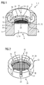
- in einer perspektivischen Querschnittsdarstellung ein gehörgangseitiges Ende eines Hörhilfegeräts mit einem eine Schallauslassöffnung umfassenden Hörgerätegehäuse, in die eine (Cerumen-)Schutzeinrichtung eingesetzt ist, wobei in das Hörgerätegehäuse eine ringförmige Hohlkammer eingeformt ist, die zur Aufnahme von Cerumen mit seitlichen Durchbrüchen in der Schutzeinrichtung korrespondiert,
- FIG 2
- in einer perspektivischen Einzeldarstellung die Schutzeinrichtung des Hörhilfegeräts gemäß
FIG 1 , - FIG 3
- in Darstellung gemäß
FIG 1 das Hörhilfegerät gemäß einer zweiten Ausführungsform, in der in das Hörgerätegehäuse Verbindungskanäle eingebracht sind, die zum Ableiten von Cerumen mit den seitlichen Durchbrüchen in der Schutzeinrichtung korrespondieren, - FIG 4
- in einer geschnittenen Einzeldarstellung die Schutzeinrichtung in einer zweiten Ausführungsform, in der die Schutzeinrichtung zwei hintereinandergeschaltete Filterelemente umfasst, und
- FIG 5
- wiederum in einer perspektivischen Einzeldarstellung die Schutzeinrichtung in einer weiteren Ausführungsform, in der sich die Schutzeinrichtung zu einem Festende hin konisch verjüngt.
- FIG. 1
- 3 is a perspective cross-sectional view of a hearing aid device comprising a sound outlet opening into which a (cerumen) protective device is inserted, an annular hollow chamber being formed in the hearing device housing which corresponds to lateral openings in the protective device for receiving cerumen;
- FIG. 2
- in a perspective detailed view of the protective device of the hearing aid according to
FIG. 1 . - FIG. 3
- in illustration according to
FIG. 1 the hearing aid according to a second embodiment, in which in the hearing aid housing connecting channels are introduced, which are for discharging cerumen with the lateral Breakthroughs in the protective device correspond, - FIG. 4
- in a sectional detail representation of the protective device in a second embodiment, in which the protective device comprises two filter elements connected in series, and
- FIG. 5
- again in a perspective detail representation of the protective device in a further embodiment in which the protective device tapers conically towards a fixed end.
Einander entsprechende Teile sind in allen Figuren stets mit den gleichen Bezugszeichen versehen.Corresponding parts are always provided in all figures with the same reference numerals.
Der Schallauslasskanal 5 ist röhrenförmig ausgeführt, wobei sich dessen Durchmesser zum Ende 3 hin in einer Stufe 6 aufweitet. Der Schallauslasskanal 5 ist von einer Gehäusewand 8 des Gehäuses 2 ummantelt, die mit einer Wandfläche 10 den Schallauslasskanal 5 begrenzt. Eine dem Ohr oder Gehörgang zugewandte Seite der Gehäusewand 8 bzw. des Gehäuses 2 ist als Außenseite 11 bezeichnet.The sound outlet channel 5 is tubular, with its diameter widening toward the end 3 in a
In die Gehäusewand 8 ist in der Nähe des Endes 3 eine den Schallauslasskanal 5 radial umgebende Ringkammer 12 eingeformt, die die Wandfläche 10 zum Ende 3 hin hinterschneidet. Ein mit geringem Abstand zu der Stufe 6 in die Wandfläche 10 eingebrachter umlaufender Spalt 13 bildet den einzigen Zugang zu der Ringkammer 12.In the housing wall 8 a the sound outlet 5 radially surrounding
Um den Schallerzeuger vor Beschädigungen ("Verstopfen") durch Schmutz (Cerumen, Schweiß, Hautpartikeln) zu schützen, der entlang einer Schmutzeindringrichtung 14 (entlang der Achse des Schallauslasskanals) in das Gehäuse 2 eindringen könnte, ist gehörgangsseitig in den Schallaustrittskanal 5 eine austauschbare (Cerumen-)Schutzeinrichtung 20 eingesetzt.In order to protect the sound generator from damage ("clogging") by dirt (cerumen, sweat, skin particles), which could penetrate along a dirt intrusion direction 14 (along the axis of the sound outlet channel) into the housing 2, the audible channel 5 is exchangeable (interchangeable). Cerumen-)
Die in
Am Stirnende 26 ist das Filterelement 22 durch das Filtergehäuse 21 gehalten. Hierzu ist das Filterelement 22 im Zuge der Herstellung der Schutzeinrichtung 20 durch Umspritzung, Umgießung oder Umformung in die Umfangswand 23 integriert.At the
Das Filterelement 22 ist hier in an sich herkömmlicher Weise durch eine annähernd kreisrunde Lage aus Filtergaze gebildet. Alternativ ist das Filterelement 22 durch ein (metallisches) Sieb oder eine schalldurchlässige Membran gebildet.The
Die Umfangswand 23 ist von mehreren, über den Umfang gleichverteilt angeordneten, radialen Durchbrüchen 30 durchsetzt, die als zu dem Freiende 25 hin offene, etwa rechteckige Ausnehmungen in die Umfangswand 23 eingebracht sind. Dabei ist die Umfangswand 23 über ihre Höhe jeweils lediglich partiell durchbrochen, so dass die Umfangswand 23 am Festende 26 einen vollumfänglich geschlossenen Rand 31 aufweist. Dieser festendseitige Rand 31 der Umfangswand 23 stellt eine ausreichende Stabilität des Filtergehäuses 21 zum Einsetzen und zur Entnahme der Schutzeinrichtung 20 sicher. Zum Einsetzen und zur Entnahme der Schutzeinrichtung 20 ist zudem in die Umfangswand 23 ein Innengewinde eingeformt, mittels dessen die Schutzeinrichtung 20 auf ein entsprechendes Montagewerkzeug geschraubt werden kann. Die Höhe des Filtergehäuses 21 ist im Vergleich zu dessen Durchmesser klein bemessen.
Ist die Schutzeinrichtung 20 (wie in
Is the protective device 20 (as in
Aufgrund dieser Anordnung wird Schmutz, der entlang der Schmutzeindringrichtung 14 (d.h. entgegen einer Schallaustrittsrichtung) in den Gehäuseinnenraum 27 eintritt, durch die Durchbrüche 30 und den Ringspalt 13 hindurch in die Ringkammer 12 geleitet und in dieser Fangzone gesammelt. In diesem Fall stellt die Ringkammer 12 einen mit den Durchbrüchen 30 korrespondierenden Hohlraum dar. Bei Bedarf wird die Ringkammer 12 gereinigt und geleert.Due to this arrangement, dirt entering the
In
Die Umfangswand 23 ist in
Der Gegenstand der Erfindung ist nicht auf die vorstehend beschriebenen Ausführungsbeispiele beschränkt. Vielmehr können weitere Ausführungsformen der Erfindung aus den Ansprüchen und der vorstehenden Beschreibung abgeleitet werden. Insbesondere können die anhand der
Claims (10)
wobei bei bestimmungsgemäß eingesetzter Schutzeinrichtung (20) mittels des Durchbruchs (5) eine fluidtechnische Verbindung zwischen dem Gehäuseinnenraum (27) des Filtergehäuses (21) und dem Hohlraum (12, 40) besteht, so dass Schmutz durch den Durchbruch (5) hindurch aus dem Gehäuseinnenraum (27) in den Hohlraum (12, 40) herausgeleitet wird.Hearing aid (1)
wherein when used as intended protective device (20) by means of the opening (5) a fluidic connection between the housing interior (27) of the filter housing (21) and the cavity (12, 40), so that dirt through the opening (5) through from the Housing interior (27) in the cavity (12, 40) is led out.
wobei der oder jeder Hohlraum durch eine zu dem Durchbruch (30) hin offene Auffangkammer (12) gebildet ist.Hearing aid (1) according to claim 1,
wherein the or each cavity is formed by a collecting chamber (12) open towards the aperture (30).
wobei die Auffangkammer als die Durchgangsöffnung (5) radial umgreifende Ringkammer (12) gebildet ist.Hearing aid (1) according to claim 2,
wherein the collecting chamber as the through-opening (5) radially surrounding annular chamber (12) is formed.
wobei der oder jeder Hohlraum durch einen Verbindungskanal (40) gebildet ist, der ausgehend von der Wandfläche (10) zu einer Außenseite (11) des Hörgerätegehäuses (2) führt.Hearing aid (1) according to one of claims 1 to 3,
wherein the or each cavity is formed by a connecting channel (40), which leads from the wall surface (10) to an outer side (11) of the hearing aid housing (2).
wobei der oder jeder Verbindungskanal (40) schräg in Richtung eines bestimmungsgemäß gehörgangseitig angeordneten Endes (3) des Hörgerätegehäuses (2) verläuft.Hearing aid (1) according to claim 4,
wherein the or each connecting channel (40) extends obliquely in the direction of an intended end of the ear (3) of the hearing aid housing (2).
wobei sich der oder jeder Verbindungskanal (40) ausgehend von seinem innenseitigen Ende zu seinem außenseitigen Ende hin konisch aufweitet.Hearing aid (1) according to claim 4 or 5,
wherein the or each connecting channel (40) widens conically from its inside end to its outside end.
mit einem Filtergehäuse (21), in dessen einen Gehäuseinnenraum (27) des Filtergehäuses (21) einfassende Umfangswand (23) mindestens ein Durchbruch (30) eingebracht ist, der mit dem in dem Hörgerätegehäuse (2) ausgebildeten Hohlraum (12, 40) korrespondiert, so dass Schmutz aus dem Gehäuseinnenraum (27) durch den Durchbruch (30) hindurch in den Hohlraum (12, 40) herausgeleitet wird, wenn die Cerumen-Schutzeinrichtung (20) bestimmungsgemäß in die Durchgangsöffnung (5) des Hörgerätegehäuses (2) eingesetzt ist.Cerumen protection device (20) for a hearing aid (1) according to one of claims 1 to 6,
with a filter housing (21), in which a housing interior (27) of the filter housing (21) enclosing peripheral wall (23) at least one aperture (30) is introduced, which corresponds to the in the hearing aid housing (2) formed cavity (12, 40) , so that dirt from the housing interior (27) through the opening (30) is passed through into the cavity (12, 40) when the cerumen protection device (20) is intended in the through hole (5) of the hearing aid housing (2) inserted ,
wobei der oder jeder Durchbruch (30) als einseitig offene Ausnehmung in die Umfangswand (23) eingebracht ist.Cerumen protection device (20) according to claim 7,
wherein the or each aperture (30) is introduced as a recess open on one side in the peripheral wall (23).
mit mindestens zwei Filterelementen (22), die in Schmutzeindringrichtung (14) hintereinander geschaltet sind.Cerumen protection device (20) according to claim 7 or 8,
with at least two filter elements (22) which are connected in series in the groove penetration direction (14).
wobei das Filtergehäuse (21) an einem bestimmungsgemäß dem Innenraum (4) des Hörgerätegehäuses (2) zugewandten Stirnende (26) konisch zuläuft.Cerumen protection device (20) according to one of claims 7 to 9,
wherein the filter housing (21) tapers conically towards a front end (26) facing the interior (4) of the hearing aid housing (2) as intended.
Applications Claiming Priority (1)
| Application Number | Priority Date | Filing Date | Title |
|---|---|---|---|
| DE102015204250.2A DE102015204250A1 (en) | 2015-03-10 | 2015-03-10 | Hearing aid with a cerumen protection device and cerumen protection device |
Publications (2)
| Publication Number | Publication Date |
|---|---|
| EP3068147A1 true EP3068147A1 (en) | 2016-09-14 |
| EP3068147B1 EP3068147B1 (en) | 2018-05-23 |
Family
ID=55353030
Family Applications (1)
| Application Number | Title | Priority Date | Filing Date |
|---|---|---|---|
| EP16154759.1A Active EP3068147B1 (en) | 2015-03-10 | 2016-02-09 | Hearing aid with a cerumen protection device and cerumen protection device |
Country Status (5)
| Country | Link |
|---|---|
| US (1) | US9980067B2 (en) |
| EP (1) | EP3068147B1 (en) |
| CN (1) | CN105979457B (en) |
| DE (1) | DE102015204250A1 (en) |
| DK (1) | DK3068147T3 (en) |
Cited By (1)
| Publication number | Priority date | Publication date | Assignee | Title |
|---|---|---|---|---|
| EP3817403A1 (en) * | 2020-03-25 | 2021-05-05 | Oticon A/s | Cap with wax filter for a hearing device |
Families Citing this family (6)
| Publication number | Priority date | Publication date | Assignee | Title |
|---|---|---|---|---|
| US10835931B2 (en) * | 2017-10-17 | 2020-11-17 | Eargo, Inc. | Device-cleaning wax guards |
| US11140498B2 (en) * | 2017-10-17 | 2021-10-05 | Eargo, Inc. | Wax management system |
| US10536764B2 (en) * | 2018-01-08 | 2020-01-14 | Bose Corporation | Integrating wax guards into earphone ear tips |
| EP3570561A1 (en) * | 2018-05-17 | 2019-11-20 | Oticon A/s | Wax filter for a speaker of hearing aid |
| US11622214B2 (en) * | 2021-03-18 | 2023-04-04 | Bose Corporation | Ear tip with wax guard |
| KR102440468B1 (en) * | 2021-06-17 | 2022-09-06 | 부전전자 주식회사 | Eartip having silicon foam type flange |
Citations (7)
| Publication number | Priority date | Publication date | Assignee | Title |
|---|---|---|---|---|
| US4972488A (en) | 1987-04-13 | 1990-11-20 | Beltone Electronics Corporation | Ear wax barrier and acoustic attenuator for a hearing aid |
| US5166659A (en) * | 1990-11-09 | 1992-11-24 | Navarro Marvin R | Hearing aid with cerumen collection cavity |
| JP2005252420A (en) * | 2004-03-02 | 2005-09-15 | Rion Co Ltd | Ear hole-shaped hearing aid |
| JP2008301306A (en) * | 2007-06-01 | 2008-12-11 | Rion Co Ltd | Hearing aid |
| US20100040250A1 (en) * | 2008-08-18 | 2010-02-18 | Anton Gebert | Hearing Aid Device with a Transducer Protection Facility |
| DE102010013447A1 (en) * | 2010-03-30 | 2011-06-09 | Siemens Medical Instruments Pte. Ltd. | Protection device for protecting e.g. microphone opening of hearing aid from cerumen, has casing connected with plate and comprising openings opening into intermediate space between plate and membrane |
| US20140193012A1 (en) | 2013-01-07 | 2014-07-10 | Oticon A/S | Hearing aid component with earwax filter |
Family Cites Families (13)
| Publication number | Priority date | Publication date | Assignee | Title |
|---|---|---|---|---|
| CA1221315A (en) * | 1984-10-19 | 1987-05-05 | William J. Gastmeier | Hearing aid wax guard |
| US5185802A (en) * | 1990-04-12 | 1993-02-09 | Beltone Electronics Corporation | Modular hearing aid system |
| US5712918A (en) * | 1995-01-27 | 1998-01-27 | Beltone Electronics Corporation | Press-fit ear wax barrier |
| US6135235A (en) * | 1999-04-06 | 2000-10-24 | Sonic Innovations, Inc. | Self-cleaning cerumen guard for a hearing device |
| WO2002076140A2 (en) * | 2001-03-16 | 2002-09-26 | Jaromir Kulman | Housing for a hearing aid |
| DE10320861B3 (en) * | 2003-05-09 | 2004-12-02 | Siemens Audiologische Technik Gmbh | cerumen protection |
| US7558394B2 (en) * | 2005-02-14 | 2009-07-07 | Insound Medical, Inc. | Systems and methods for in situ cerumen removal from hearing devices |
| DE102006008044B3 (en) * | 2006-02-21 | 2007-05-10 | Siemens Audiologische Technik Gmbh | In-the-ear hearing aid, has ventilation channel with openings in first- and second-housing zones |
| US20080118095A1 (en) * | 2006-11-22 | 2008-05-22 | Fletcher Thomas G | Wax guard for a hearing aid |
| JP5091711B2 (en) * | 2008-02-20 | 2012-12-05 | リオン株式会社 | Ear wax intrusion prevention chip and hearing aid |
| EP2393311A1 (en) * | 2010-06-07 | 2011-12-07 | Sonion A/S | A cerumen filter for a hearing aid |
| US9485595B2 (en) * | 2014-08-25 | 2016-11-01 | Starkey Laboratories, Inc. | Inverted flange earbud |
| US20160165334A1 (en) * | 2014-12-03 | 2016-06-09 | Knowles Electronics, Llc | Hearing device with self-cleaning tubing |
-
2015
- 2015-03-10 DE DE102015204250.2A patent/DE102015204250A1/en not_active Withdrawn
-
2016
- 2016-02-09 DK DK16154759.1T patent/DK3068147T3/en active
- 2016-02-09 EP EP16154759.1A patent/EP3068147B1/en active Active
- 2016-03-09 CN CN201610134148.3A patent/CN105979457B/en active Active
- 2016-03-10 US US15/066,131 patent/US9980067B2/en active Active
Patent Citations (7)
| Publication number | Priority date | Publication date | Assignee | Title |
|---|---|---|---|---|
| US4972488A (en) | 1987-04-13 | 1990-11-20 | Beltone Electronics Corporation | Ear wax barrier and acoustic attenuator for a hearing aid |
| US5166659A (en) * | 1990-11-09 | 1992-11-24 | Navarro Marvin R | Hearing aid with cerumen collection cavity |
| JP2005252420A (en) * | 2004-03-02 | 2005-09-15 | Rion Co Ltd | Ear hole-shaped hearing aid |
| JP2008301306A (en) * | 2007-06-01 | 2008-12-11 | Rion Co Ltd | Hearing aid |
| US20100040250A1 (en) * | 2008-08-18 | 2010-02-18 | Anton Gebert | Hearing Aid Device with a Transducer Protection Facility |
| DE102010013447A1 (en) * | 2010-03-30 | 2011-06-09 | Siemens Medical Instruments Pte. Ltd. | Protection device for protecting e.g. microphone opening of hearing aid from cerumen, has casing connected with plate and comprising openings opening into intermediate space between plate and membrane |
| US20140193012A1 (en) | 2013-01-07 | 2014-07-10 | Oticon A/S | Hearing aid component with earwax filter |
Cited By (1)
| Publication number | Priority date | Publication date | Assignee | Title |
|---|---|---|---|---|
| EP3817403A1 (en) * | 2020-03-25 | 2021-05-05 | Oticon A/s | Cap with wax filter for a hearing device |
Also Published As
| Publication number | Publication date |
|---|---|
| DK3068147T3 (en) | 2018-09-03 |
| US9980067B2 (en) | 2018-05-22 |
| CN105979457B (en) | 2019-05-14 |
| US20160269840A1 (en) | 2016-09-15 |
| DE102015204250A1 (en) | 2016-09-15 |
| EP3068147B1 (en) | 2018-05-23 |
| CN105979457A (en) | 2016-09-28 |
Similar Documents
| Publication | Publication Date | Title |
|---|---|---|
| EP3068147B1 (en) | Hearing aid with a cerumen protection device and cerumen protection device | |
| DE3811881C2 (en) | ||
| DE3736591C2 (en) | ||
| DE102006008044B3 (en) | In-the-ear hearing aid, has ventilation channel with openings in first- and second-housing zones | |
| DE102007037024A1 (en) | Hearing device with elastically mounted handset | |
| EP1596631A2 (en) | Hearing-aid with cerumen barrier | |
| DE102007058987B3 (en) | Face plate with closure device | |
| EP3249954B1 (en) | Retaining ear tip for a standard earpiece | |
| EP2200343A1 (en) | Hearing aid with directional microphone | |
| EP1562400B1 (en) | Replaceable protective membrane of listening device of hearing-aids | |
| EP2003930B1 (en) | Hearing aid with connecting piece attached to case frame | |
| EP3419311B1 (en) | Hearing aid | |
| EP3481084B1 (en) | Hearing aid | |
| EP1993323A1 (en) | Earpiece for a hearing aid with bayonet fixing | |
| DE102005009377B3 (en) | Hearing aid, has two housings respectively accommodating microphone and amplifier, and loudspeaker, where mechanical connection between housings is realized by bayonet-fastener typical groove | |
| DE102014200605A1 (en) | Dome with cerumen protection | |
| EP1906703A1 (en) | Otoplastic with connecting device | |
| DE102007025446B3 (en) | Ear piece for a hearing device with retaining ring | |
| DE10104129A1 (en) | Hearing aid incorporates a preferably changeable filter unit which prevents entry of moisture and/or dirt, in particular, cerumen, and includes a filter element constituted as a membrane and/or a sieve | |
| EP1439733B1 (en) | Microphone protection for hearing aids | |
| EP3554097B1 (en) | Dome for hearing aid insertable in an ear canal | |
| DE2949992A1 (en) | IN-EAR HEARING DEVICE FOR HEALTHY HEALTH | |
| EP3439329B1 (en) | In-the-ear hearing aid | |
| DE19943809A1 (en) | Hearing aid has plastic ear fitting matching outer ear canal, outlet opening on inner end on eardrum side; ear fitting is connected to protruding body with sound canal connected to outlet | |
| DE102017201465B4 (en) | Microphone unit with a housing |
Legal Events
| Date | Code | Title | Description |
|---|---|---|---|
| PUAI | Public reference made under article 153(3) epc to a published international application that has entered the european phase |
Free format text: ORIGINAL CODE: 0009012 |
|
| AK | Designated contracting states |
Kind code of ref document: A1 Designated state(s): AL AT BE BG CH CY CZ DE DK EE ES FI FR GB GR HR HU IE IS IT LI LT LU LV MC MK MT NL NO PL PT RO RS SE SI SK SM TR |
|
| AX | Request for extension of the european patent |
Extension state: BA ME |
|
| STAA | Information on the status of an ep patent application or granted ep patent |
Free format text: STATUS: REQUEST FOR EXAMINATION WAS MADE |
|
| 17P | Request for examination filed |
Effective date: 20170314 |
|
| RBV | Designated contracting states (corrected) |
Designated state(s): AL AT BE BG CH CY CZ DE DK EE ES FI FR GB GR HR HU IE IS IT LI LT LU LV MC MK MT NL NO PL PT RO RS SE SI SK SM TR |
|
| GRAP | Despatch of communication of intention to grant a patent |
Free format text: ORIGINAL CODE: EPIDOSNIGR1 |
|
| STAA | Information on the status of an ep patent application or granted ep patent |
Free format text: STATUS: GRANT OF PATENT IS INTENDED |
|
| INTG | Intention to grant announced |
Effective date: 20180108 |
|
| RAP1 | Party data changed (applicant data changed or rights of an application transferred) |
Owner name: SIVANTOS PTE. LTD. |
|
| GRAS | Grant fee paid |
Free format text: ORIGINAL CODE: EPIDOSNIGR3 |
|
| GRAA | (expected) grant |
Free format text: ORIGINAL CODE: 0009210 |
|
| STAA | Information on the status of an ep patent application or granted ep patent |
Free format text: STATUS: THE PATENT HAS BEEN GRANTED |
|
| AK | Designated contracting states |
Kind code of ref document: B1 Designated state(s): AL AT BE BG CH CY CZ DE DK EE ES FI FR GB GR HR HU IE IS IT LI LT LU LV MC MK MT NL NO PL PT RO RS SE SI SK SM TR |
|
| REG | Reference to a national code |
Ref country code: GB Ref legal event code: FG4D Free format text: NOT ENGLISH |
|
| REG | Reference to a national code |
Ref country code: CH Ref legal event code: EP |
|
| REG | Reference to a national code |
Ref country code: IE Ref legal event code: FG4D Free format text: LANGUAGE OF EP DOCUMENT: GERMAN |
|
| REG | Reference to a national code |
Ref country code: CH Ref legal event code: NV Representative=s name: E. BLUM AND CO. AG PATENT- UND MARKENANWAELTE , CH Ref country code: AT Ref legal event code: REF Ref document number: 1002496 Country of ref document: AT Kind code of ref document: T Effective date: 20180615 |
|
| REG | Reference to a national code |
Ref country code: DE Ref legal event code: R096 Ref document number: 502016001083 Country of ref document: DE |
|
| REG | Reference to a national code |
Ref country code: DK Ref legal event code: T3 Effective date: 20180827 |
|
| REG | Reference to a national code |
Ref country code: NL Ref legal event code: MP Effective date: 20180523 |
|
| REG | Reference to a national code |
Ref country code: LT Ref legal event code: MG4D |
|
| PG25 | Lapsed in a contracting state [announced via postgrant information from national office to epo] |
Ref country code: SE Free format text: LAPSE BECAUSE OF FAILURE TO SUBMIT A TRANSLATION OF THE DESCRIPTION OR TO PAY THE FEE WITHIN THE PRESCRIBED TIME-LIMIT Effective date: 20180523 Ref country code: ES Free format text: LAPSE BECAUSE OF FAILURE TO SUBMIT A TRANSLATION OF THE DESCRIPTION OR TO PAY THE FEE WITHIN THE PRESCRIBED TIME-LIMIT Effective date: 20180523 Ref country code: LT Free format text: LAPSE BECAUSE OF FAILURE TO SUBMIT A TRANSLATION OF THE DESCRIPTION OR TO PAY THE FEE WITHIN THE PRESCRIBED TIME-LIMIT Effective date: 20180523 Ref country code: NO Free format text: LAPSE BECAUSE OF FAILURE TO SUBMIT A TRANSLATION OF THE DESCRIPTION OR TO PAY THE FEE WITHIN THE PRESCRIBED TIME-LIMIT Effective date: 20180823 Ref country code: FI Free format text: LAPSE BECAUSE OF FAILURE TO SUBMIT A TRANSLATION OF THE DESCRIPTION OR TO PAY THE FEE WITHIN THE PRESCRIBED TIME-LIMIT Effective date: 20180523 Ref country code: BG Free format text: LAPSE BECAUSE OF FAILURE TO SUBMIT A TRANSLATION OF THE DESCRIPTION OR TO PAY THE FEE WITHIN THE PRESCRIBED TIME-LIMIT Effective date: 20180823 |
|
| PG25 | Lapsed in a contracting state [announced via postgrant information from national office to epo] |
Ref country code: RS Free format text: LAPSE BECAUSE OF FAILURE TO SUBMIT A TRANSLATION OF THE DESCRIPTION OR TO PAY THE FEE WITHIN THE PRESCRIBED TIME-LIMIT Effective date: 20180523 Ref country code: NL Free format text: LAPSE BECAUSE OF FAILURE TO SUBMIT A TRANSLATION OF THE DESCRIPTION OR TO PAY THE FEE WITHIN THE PRESCRIBED TIME-LIMIT Effective date: 20180523 Ref country code: LV Free format text: LAPSE BECAUSE OF FAILURE TO SUBMIT A TRANSLATION OF THE DESCRIPTION OR TO PAY THE FEE WITHIN THE PRESCRIBED TIME-LIMIT Effective date: 20180523 Ref country code: GR Free format text: LAPSE BECAUSE OF FAILURE TO SUBMIT A TRANSLATION OF THE DESCRIPTION OR TO PAY THE FEE WITHIN THE PRESCRIBED TIME-LIMIT Effective date: 20180824 Ref country code: HR Free format text: LAPSE BECAUSE OF FAILURE TO SUBMIT A TRANSLATION OF THE DESCRIPTION OR TO PAY THE FEE WITHIN THE PRESCRIBED TIME-LIMIT Effective date: 20180523 |
|
| PG25 | Lapsed in a contracting state [announced via postgrant information from national office to epo] |
Ref country code: RO Free format text: LAPSE BECAUSE OF FAILURE TO SUBMIT A TRANSLATION OF THE DESCRIPTION OR TO PAY THE FEE WITHIN THE PRESCRIBED TIME-LIMIT Effective date: 20180523 Ref country code: SK Free format text: LAPSE BECAUSE OF FAILURE TO SUBMIT A TRANSLATION OF THE DESCRIPTION OR TO PAY THE FEE WITHIN THE PRESCRIBED TIME-LIMIT Effective date: 20180523 Ref country code: EE Free format text: LAPSE BECAUSE OF FAILURE TO SUBMIT A TRANSLATION OF THE DESCRIPTION OR TO PAY THE FEE WITHIN THE PRESCRIBED TIME-LIMIT Effective date: 20180523 Ref country code: PL Free format text: LAPSE BECAUSE OF FAILURE TO SUBMIT A TRANSLATION OF THE DESCRIPTION OR TO PAY THE FEE WITHIN THE PRESCRIBED TIME-LIMIT Effective date: 20180523 Ref country code: CZ Free format text: LAPSE BECAUSE OF FAILURE TO SUBMIT A TRANSLATION OF THE DESCRIPTION OR TO PAY THE FEE WITHIN THE PRESCRIBED TIME-LIMIT Effective date: 20180523 |
|
| REG | Reference to a national code |
Ref country code: DE Ref legal event code: R097 Ref document number: 502016001083 Country of ref document: DE |
|
| PG25 | Lapsed in a contracting state [announced via postgrant information from national office to epo] |
Ref country code: IT Free format text: LAPSE BECAUSE OF FAILURE TO SUBMIT A TRANSLATION OF THE DESCRIPTION OR TO PAY THE FEE WITHIN THE PRESCRIBED TIME-LIMIT Effective date: 20180523 Ref country code: SM Free format text: LAPSE BECAUSE OF FAILURE TO SUBMIT A TRANSLATION OF THE DESCRIPTION OR TO PAY THE FEE WITHIN THE PRESCRIBED TIME-LIMIT Effective date: 20180523 |
|
| PLBE | No opposition filed within time limit |
Free format text: ORIGINAL CODE: 0009261 |
|
| STAA | Information on the status of an ep patent application or granted ep patent |
Free format text: STATUS: NO OPPOSITION FILED WITHIN TIME LIMIT |
|
| 26N | No opposition filed |
Effective date: 20190226 |
|
| PG25 | Lapsed in a contracting state [announced via postgrant information from national office to epo] |
Ref country code: SI Free format text: LAPSE BECAUSE OF FAILURE TO SUBMIT A TRANSLATION OF THE DESCRIPTION OR TO PAY THE FEE WITHIN THE PRESCRIBED TIME-LIMIT Effective date: 20180523 |
|
| PG25 | Lapsed in a contracting state [announced via postgrant information from national office to epo] |
Ref country code: LU Free format text: LAPSE BECAUSE OF NON-PAYMENT OF DUE FEES Effective date: 20190209 Ref country code: MC Free format text: LAPSE BECAUSE OF FAILURE TO SUBMIT A TRANSLATION OF THE DESCRIPTION OR TO PAY THE FEE WITHIN THE PRESCRIBED TIME-LIMIT Effective date: 20180523 |
|
| REG | Reference to a national code |
Ref country code: BE Ref legal event code: MM Effective date: 20190228 |
|
| REG | Reference to a national code |
Ref country code: IE Ref legal event code: MM4A |
|
| PG25 | Lapsed in a contracting state [announced via postgrant information from national office to epo] |
Ref country code: AL Free format text: LAPSE BECAUSE OF FAILURE TO SUBMIT A TRANSLATION OF THE DESCRIPTION OR TO PAY THE FEE WITHIN THE PRESCRIBED TIME-LIMIT Effective date: 20180523 |
|
| PG25 | Lapsed in a contracting state [announced via postgrant information from national office to epo] |
Ref country code: IE Free format text: LAPSE BECAUSE OF NON-PAYMENT OF DUE FEES Effective date: 20190209 |
|
| PG25 | Lapsed in a contracting state [announced via postgrant information from national office to epo] |
Ref country code: BE Free format text: LAPSE BECAUSE OF NON-PAYMENT OF DUE FEES Effective date: 20190228 |
|
| PG25 | Lapsed in a contracting state [announced via postgrant information from national office to epo] |
Ref country code: TR Free format text: LAPSE BECAUSE OF FAILURE TO SUBMIT A TRANSLATION OF THE DESCRIPTION OR TO PAY THE FEE WITHIN THE PRESCRIBED TIME-LIMIT Effective date: 20180523 |
|
| PG25 | Lapsed in a contracting state [announced via postgrant information from national office to epo] |
Ref country code: PT Free format text: LAPSE BECAUSE OF FAILURE TO SUBMIT A TRANSLATION OF THE DESCRIPTION OR TO PAY THE FEE WITHIN THE PRESCRIBED TIME-LIMIT Effective date: 20180924 Ref country code: MT Free format text: LAPSE BECAUSE OF FAILURE TO SUBMIT A TRANSLATION OF THE DESCRIPTION OR TO PAY THE FEE WITHIN THE PRESCRIBED TIME-LIMIT Effective date: 20180523 |
|
| PG25 | Lapsed in a contracting state [announced via postgrant information from national office to epo] |
Ref country code: CY Free format text: LAPSE BECAUSE OF FAILURE TO SUBMIT A TRANSLATION OF THE DESCRIPTION OR TO PAY THE FEE WITHIN THE PRESCRIBED TIME-LIMIT Effective date: 20180523 |
|
| PG25 | Lapsed in a contracting state [announced via postgrant information from national office to epo] |
Ref country code: IS Free format text: LAPSE BECAUSE OF FAILURE TO SUBMIT A TRANSLATION OF THE DESCRIPTION OR TO PAY THE FEE WITHIN THE PRESCRIBED TIME-LIMIT Effective date: 20180923 |
|
| PG25 | Lapsed in a contracting state [announced via postgrant information from national office to epo] |
Ref country code: HU Free format text: LAPSE BECAUSE OF FAILURE TO SUBMIT A TRANSLATION OF THE DESCRIPTION OR TO PAY THE FEE WITHIN THE PRESCRIBED TIME-LIMIT; INVALID AB INITIO Effective date: 20160209 |
|
| REG | Reference to a national code |
Ref country code: AT Ref legal event code: MM01 Ref document number: 1002496 Country of ref document: AT Kind code of ref document: T Effective date: 20210209 |
|
| PG25 | Lapsed in a contracting state [announced via postgrant information from national office to epo] |
Ref country code: AT Free format text: LAPSE BECAUSE OF NON-PAYMENT OF DUE FEES Effective date: 20210209 |
|
| PG25 | Lapsed in a contracting state [announced via postgrant information from national office to epo] |
Ref country code: MK Free format text: LAPSE BECAUSE OF FAILURE TO SUBMIT A TRANSLATION OF THE DESCRIPTION OR TO PAY THE FEE WITHIN THE PRESCRIBED TIME-LIMIT Effective date: 20180523 |
|
| PGFP | Annual fee paid to national office [announced via postgrant information from national office to epo] |
Ref country code: FR Payment date: 20230217 Year of fee payment: 8 Ref country code: DK Payment date: 20230220 Year of fee payment: 8 |
|
| PGFP | Annual fee paid to national office [announced via postgrant information from national office to epo] |
Ref country code: DE Payment date: 20240216 Year of fee payment: 9 Ref country code: GB Payment date: 20240222 Year of fee payment: 9 Ref country code: CH Payment date: 20240301 Year of fee payment: 9 |