EP3067164B1 - Joint driving apparatus and robot apparatus - Google Patents
Joint driving apparatus and robot apparatus Download PDFInfo
- Publication number
- EP3067164B1 EP3067164B1 EP16159566.5A EP16159566A EP3067164B1 EP 3067164 B1 EP3067164 B1 EP 3067164B1 EP 16159566 A EP16159566 A EP 16159566A EP 3067164 B1 EP3067164 B1 EP 3067164B1
- Authority
- EP
- European Patent Office
- Prior art keywords
- unit
- torque
- driving
- joint
- link
- Prior art date
- Legal status (The legal status is an assumption and is not a legal conclusion. Google has not performed a legal analysis and makes no representation as to the accuracy of the status listed.)
- Active
Links
- 238000001514 detection method Methods 0.000 claims description 77
- 230000007246 mechanism Effects 0.000 claims description 77
- 230000009467 reduction Effects 0.000 claims description 50
- 238000004519 manufacturing process Methods 0.000 claims description 6
- 230000033001 locomotion Effects 0.000 description 14
- 230000006870 function Effects 0.000 description 10
- 230000005540 biological transmission Effects 0.000 description 8
- 238000010586 diagram Methods 0.000 description 7
- 238000003860 storage Methods 0.000 description 7
- 238000005259 measurement Methods 0.000 description 5
- 230000003287 optical effect Effects 0.000 description 5
- 238000006243 chemical reaction Methods 0.000 description 4
- 238000006073 displacement reaction Methods 0.000 description 4
- 230000008901 benefit Effects 0.000 description 3
- 238000000034 method Methods 0.000 description 3
- 230000004043 responsiveness Effects 0.000 description 3
- 238000011161 development Methods 0.000 description 2
- 230000018109 developmental process Effects 0.000 description 2
- 238000009434 installation Methods 0.000 description 2
- 238000005304 joining Methods 0.000 description 2
- 239000000463 material Substances 0.000 description 2
- 238000012545 processing Methods 0.000 description 2
- 229910000838 Al alloy Inorganic materials 0.000 description 1
- 230000001133 acceleration Effects 0.000 description 1
- 230000008859 change Effects 0.000 description 1
- 238000007796 conventional method Methods 0.000 description 1
- 230000001419 dependent effect Effects 0.000 description 1
- 238000013461 design Methods 0.000 description 1
- 230000006866 deterioration Effects 0.000 description 1
- 239000012636 effector Substances 0.000 description 1
- 239000012530 fluid Substances 0.000 description 1
- 230000006872 improvement Effects 0.000 description 1
- 230000002452 interceptive effect Effects 0.000 description 1
- 229910052751 metal Inorganic materials 0.000 description 1
- 239000002184 metal Substances 0.000 description 1
- 239000000203 mixture Substances 0.000 description 1
- 238000012986 modification Methods 0.000 description 1
- 230000004048 modification Effects 0.000 description 1
- 230000008569 process Effects 0.000 description 1
- 239000011347 resin Substances 0.000 description 1
- 229920005989 resin Polymers 0.000 description 1
Images


Classifications
-
- B—PERFORMING OPERATIONS; TRANSPORTING
- B25—HAND TOOLS; PORTABLE POWER-DRIVEN TOOLS; MANIPULATORS
- B25J—MANIPULATORS; CHAMBERS PROVIDED WITH MANIPULATION DEVICES
- B25J9/00—Programme-controlled manipulators
- B25J9/16—Programme controls
- B25J9/1628—Programme controls characterised by the control loop
- B25J9/1633—Programme controls characterised by the control loop compliant, force, torque control, e.g. combined with position control
-
- B—PERFORMING OPERATIONS; TRANSPORTING
- B25—HAND TOOLS; PORTABLE POWER-DRIVEN TOOLS; MANIPULATORS
- B25J—MANIPULATORS; CHAMBERS PROVIDED WITH MANIPULATION DEVICES
- B25J17/00—Joints
-
- B—PERFORMING OPERATIONS; TRANSPORTING
- B25—HAND TOOLS; PORTABLE POWER-DRIVEN TOOLS; MANIPULATORS
- B25J—MANIPULATORS; CHAMBERS PROVIDED WITH MANIPULATION DEVICES
- B25J9/00—Programme-controlled manipulators
- B25J9/10—Programme-controlled manipulators characterised by positioning means for manipulator elements
- B25J9/12—Programme-controlled manipulators characterised by positioning means for manipulator elements electric
- B25J9/126—Rotary actuators
-
- B—PERFORMING OPERATIONS; TRANSPORTING
- B25—HAND TOOLS; PORTABLE POWER-DRIVEN TOOLS; MANIPULATORS
- B25J—MANIPULATORS; CHAMBERS PROVIDED WITH MANIPULATION DEVICES
- B25J13/00—Controls for manipulators
- B25J13/08—Controls for manipulators by means of sensing devices, e.g. viewing or touching devices
- B25J13/085—Force or torque sensors
-
- B—PERFORMING OPERATIONS; TRANSPORTING
- B25—HAND TOOLS; PORTABLE POWER-DRIVEN TOOLS; MANIPULATORS
- B25J—MANIPULATORS; CHAMBERS PROVIDED WITH MANIPULATION DEVICES
- B25J17/00—Joints
- B25J17/02—Wrist joints
- B25J17/0208—Compliance devices
Definitions
- the present invention relates to a joint driving apparatus according to the preamble of claim 1 as well as to a robot apparatus equipped with the driving apparatus and to a manufacturing method using the robot.
- articuleted robot manipulators have been finding increasingly wider uses and expanding their application to areas, such as collaborative work with humans and assembly work in a factory, in which robots are required to perform flexible movements.
- a stable and wide-band force control function is required of such a robot apparatus to follow external forces.
- torque servo joint-level torque control
- position servo joint position control
- the torque control requires a torque detection unit capable of accurately detecting torque which is output from joints of a robot arm.
- a multi-joint robot which is made up of plural links coupled by plural joint drive shafts.
- Such a multi-joint robot arm is configured such that forces acting on a member on an end side accumulate and act on a base member (base or mount).
- base member base or mount
- this type of joint driving apparatus a configuration is known in which a torque detection apparatus adapted to measure output torque of the joint via a bearing adapted to rotatably support an output link is installed between an output shaft (final stage) of the joint driving apparatus, including a motor and a reduction mechanism, and a drive shaft of an output link.
- this type of torque detection apparatus is made up of a strain gage or an elastic member adapted to deform according to applied torque and a sensor device adapted to detect a deformation amount or distortion amount of the elastic member, for example, optically or magnetically.
- a robot arm equipped with a torque sensor is disclosed in " A. Albu-Schaeffer, S. Haddadin, Ch. Ott, A. Stemmer, T. Wimboeck, G. Hirzinger, "The DLR lightweight robot: design and control concepts for robots in human environments", Industrial Robot: An International Journal, Vol.34, Iss: 5, pp.376 - 385 (2007 )” (hereinafter, referred to as an article by A. Albu-Schaeffer et al.).
- the torque sensor rotates together with a measuring object, causing, for example, a sensor cable attached to the torque sensor to deform along with motion of the drive shaft. Consequently, there is a problem in that when a reaction force from the sensor cable cannot be ignored, such as when a robot joint has a large operation angle, it is difficult to detect torque accurately. Also, with the configuration in the article by A. Albu-Schaeffer et al., a cable routing mechanism tends to become complicated, and it is not easy to ensure durability of the sensor cable.
- JP 2012-047460 A As a torque detection apparatus for a drive system of a sphere tire adapted to move a robot apparatus, a configuration is proposed, for example, in JP 2012-047460 A .
- the configuration disclosed in JP 2012-047460 A includes a driving unit made up of a rotor and a stator, where the rotor has a spindle in a first axial direction and the stator causes the rotor to rotate around the spindle.
- the torque detection apparatus includes a strain body and a detection element, where the strain body is placed concentrically with the rotor and provided with a first end portion fixed to a base portion and a second end portion fixed to the stator while the detection element is attached to the strain body and adapted to detect distortion of the strain body around a first axis.
- the strain body (elastic member) of the torque detection apparatus is placed between the base portion and a support mechanism (bearing) for the driving mechanism.
- a force acting on a driving torque output link acts directly on the strain body, posing a problem in that a torque sensor is susceptible to cross-axis components when the configuration is applied to a joint mechanism of the robot apparatus. Consequently, sensor output values may fluctuate under the influence of disturbance forces other than the desired torque around the drive shaft, which could result in a failure to detect output torque accurately (hereinafter, this problem will be referred to as interfering with the other axis or crosstalk).
- JP 2012-047460 A presents a configuration in which the driving mechanism is pivotally supported by the support mechanism made up of the bearing and a frame body to reduce the influence of cross-axis forces acting on the elastic member of the torque sensor such as described above.
- this configuration will increase in complexity and size because of the support mechanism which supports the driving mechanism.
- rigidity and strength equal to or higher than those of links joined via the joint have to be secured for the bearing of the support mechanism for the driving mechanism in order to maintain rigidity and strength of the entire joint.
- a joint driving apparatus of the robot apparatus a joint area may become too large in mass and size.
- JP 4 273335 B2 shows a generic joint driving apparatus according to the preamble of claim 1.
- US 5 155 423 A shows another joint driving apparatus according to the prior art.
- the object of the present invention is achieved by a joint driving apparatus having the features of claim 1 and a manufacturing method having the features of claim 12.
- the torque sensor is installed between the driving unit and the housing unit to detect torque produced on the supporting unit adapted to support the driving unit on the housing unit.
- the torque sensor can be fixed to the first link (fixed link), eliminating the need to route sensor cables for supplying power to the torque sensor and exchanging signals. This makes the configuration of the entire driving mechanism simple and compact, allowing the entire robot apparatus to be reduced in weight. Also, deformation of the sensor cable due to rotational motion of the joint driving apparatus can be inhibited, which enables preventing deterioration of the sensor cable as well as reduction of torque detection accuracy caused by deformation resistance of the sensor cable.
- the joint driving apparatus is configured to support components of the forces acting on the second link (output link) excluding the rotational torque of a desired measurement object, using the bearing and housing unit. Therefore, cross-axis force (disturbance force) components other than the rotational torque to be detected do not act on the torque sensor adapted to detect the torque occurring on the supporting unit.
- the present invention can reduce the size and weight of the entire robot apparatus which uses the joint driving apparatus and improve the responsiveness and agility of the robot apparatus.
- a robot apparatus 1 includes a robot body 2 and a controlling apparatus 3 adapted to control the robot body 2.
- the robot body 2 is equipped with a hand 21 as an end effector in a front end portion of, for example, a six-axis vertical multi-joint robot arm (hereinafter, referred to as an arm) 20.
- the arm 20 includes seven links 61 to 67 and six joint driving apparatuses (driving apparatuses) 71 to 76 adapted to swingably or pivotably couple together the links 61 to 67.
- the hand 21 is supported by being attached to a foremost link 67 of the arm 20 and is configured such that motion (changes in position and orientation) or a force of the hand 21 will be adjusted by movement of the arm 20.
- the hand 21 includes a hand body 24 and plural fingers 23 disposed movably with respect to the hand body 24 and configured to be able to grip a workpiece W.
- the controlling apparatus 3 includes a CPU 30 made up of a general purpose microprocessor and the like.
- the CPU 30 controls movement of the robot body 2 by executing a robot control program stored, for example, in a ROM 31.
- a RAM 32 is used as a work area for program execution.
- a program storage area of the ROM 31 may be made up of a rewritable storage medium such as an EEPROM.
- the robot control program can be installed in the ROM 31 or updated by supplying programs and control data from a flash memory or optical disk (not shown) .
- the controlling apparatus 3 includes an interface 33.
- the interface 33 is used to transmit control information to the robot body 2 and input detection information from the side of the robot body 2, where the control information is used to control the movement of the joint driving apparatus 71 to 76 or hand 21 while the detection information is provided by a torque sensor (52s) described later.
- the interface 33 may include a network interface and the like.
- the robot control program can be installed in the ROM 31 or updated using programs and control data received from a network.
- the network interface described above can also be used for communications with a robot teaching terminal (teaching pendant) and an off-line control terminal for use to create and edit the robot control program (neither terminal is shown) .
- FIG. 2 shows a sectional structure of the joint driving apparatus 72 of the arm 20 as an example of the joint driving apparatus 71 to 76.
- the configuration shown in FIG. 2 is also applicable to the other joint driving apparatus 71 to 76 of the arm 20.
- After-mentioned components of the joint driving apparatus 72 are made of material such as metal, resin or the like which conform to the strength and rigidity required by specifications.
- the joint driving apparatus 72 includes a link 62 (first link) as a base-side member (fixed link) of the driving mechanism and a link 63 (second link) as an output side member (output link) of the driving mechanism.
- the link 62 (fixed link) and link 63 (output link) are configured to be rotatably coupled by a bearing 54, which is a joint support mechanism supported on the housing unit 255.
- the bearing 54 constrains rotational motion of the link 63 relative to the link 62 to allow only rotational motion around the drive shaft.
- the bearing 54 has a function to support five forces/moments ( FIG. 2 ), excluding rotational torque around the joint drive shaft, out of six-dimensional (translational) forces and moments acting on the link 63.
- a cross-roller bearing which is widely used for robot joint mechanisms, can be used for the bearing 54, but this is not restrictive and other bearing members having similar functions are available for use.
- arrow 90 indicates a force acting on the link 63.
- the force (90) acting on the link 63 can be regarded as the composition of the following components.
- the rotational torque (around z-axis) 901 is produced, controlling an orientation (angle) of the link 63 relative to the link 62.
- the bearing 54 serving as a joint support mechanism restrains rotational motion of the joint around a joint axis (alternate long and short dash line) while supporting the cross-axis forces 902 to 906 described above.
- the joint driving apparatus 72 includes a housing unit 55 configured to be approximately cylindrical in shape as a whole and adapted to house a driving unit 80 made up of the rotary drive source 51 and a reduction mechanism 53.
- the housing unit 55 stores members needed to drive the joint as well as components needed to measure output torque.
- the joining (fixing) region when a certain component is rigidly fixed to another component, the joining (fixing) region is referred to as a "fixing portion".
- a technique such as screwing (details are not shown) is used.
- a fixing portion 551 is part of the housing unit 55, which is fixed to the base-side link 62 of the joint driving apparatus 72 via the fixing portion 551.
- the housing unit 55 includes the bearing 54 adapted to rotatably support the (second) link 63. Also, the housing unit 55 houses the driving unit 80 adapted to rotationally drive the (second) link 63. In particular, the driving unit 80 is supported in the housing unit 55 such that pivot (drive) shafts will coincide each other as follows. First, a drive shaft 51a of the rotary drive source 51 of the driving unit 80 is joined to an input end 531 of the reduction mechanism 53. Also, the reduction mechanism 53 is made up of a strain wave gearing mechanism and the like, the input end 531 and an output end 533 are placed coaxially, and a pivot shaft of the link 63 is joined to the output end 533.
- a supporting unit (532, 56, 52) adapted to support the driving unit 80 on the housing unit 55 are provided between the driving unit 80 and housing unit 55.
- the supporting unit includes a fixing portion 532 of the reduction mechanism 53, a holding member 56 of the rotary drive source 51, and the torque detection apparatus 52.
- the holding member 56 and fixing portion 532 are members generally annular in shape (flange-shaped) and it is assumed that recesses (open holes) approximately cylindrical in shape are formed in their front and back surfaces, as required, to accept a front end or rear end of the rotary drive source 51 or reduction mechanism 53.
- the rotary drive source 51 is firmly fixed to the holding member 56, for example, by screwing (not shown) or the like, and the holding member 56 is firmly fixed to the fixing portion 532 of the reduction mechanism 53, for example, by screwing (not shown) or the like. Consequently, the rotary drive source 51 and reduction mechanism 53 are integrally joined (firmly fixed) together, making up the driving unit 80.
- the driving unit 80 is joined (firmly fixed) to the housing unit 55 via the torque detection apparatus 52.
- the second link 63 which is an output link, can pivot about the bearing 54 mounted in the housing unit 55, and the drive shaft of the link 63 is joined to the output end 533 of the reduction mechanism 53.
- the driving unit 80 is housed and supported in the housing unit 55 by the supporting unit (the fixing portion 532 of the reduction mechanism 53, holding member 56 of the rotary drive source 51 and torque detection apparatus 52) and the bearing 54 mounted in the housing unit 55. That is, the driving unit 80 is housed and supported at a center position of the housing unit 55 by the supporting unit (the fixing portion 532 of the reduction mechanism 53, holding member 56 of the rotary drive source 51 and torque detection apparatus 52) and the bearing 54 in such a way that a center line of the cylindrical housing unit 55 will match a drive axis.
- the rotary drive source 51 which generates a turning force (torque) to rotate a joint, is made up, for example, of an electric motor (servomotor).
- the rotary drive source 51 includes a rotary encoder for use to measure a motor rotation angle and a brake for use to hold the motor rotation angle (neither is shown). Also, the rotary drive source 51 is connected with a motor wiring cable 572 to electrically drive the motor, input and output signals from/to the rotary encoder, and control on/off operation of the brake.
- the reduction mechanism 53 is made up of the input end 531, the output end 533, and the fixing portion 532 of the reduction mechanism 53.
- a transmission mechanism of the reduction mechanism 53 is made up of, for example, a known strain wave gearing mechanism. According to the present embodiment, it is assumed that a reduction ratio of the reduction mechanism 53 is, for example, about 1:100.
- the output of the rotary drive source 51 rotationally drives the input end 531 of the reduction mechanism 53, and the reduction mechanism 53 increases the torque generated by the rotary drive source (and simultaneously reduces the rotation angle at the reduction ratio) according to the reduction ratio and outputs the increased rotational torque through the output end 533. Consequently, the torque generated by the rotary drive source 51 is increased to a level suitable to drive the joint, and the link 63 constrained by the bearing 54 is actively driven by remaining rotational degrees of freedom (rotational freedom around the drive shaft) of the output torque of the reduction mechanism 53.
- the torque which can efficiently be produced by a small electric motor is usually far smaller than the torque needed to drive a joint.
- a rated rotational speed is much larger than the rotational speed required of the output shaft of the joint. Consequently, a reduction mechanism (53) with a high reduction ratio of about 1:30 to 1:200 is commonly used by most robots.
- a combination of such a small motor and a reduction mechanism (53) with a high reduction ratio has the advantage of making the configuration compact, but has a problem in that the reduction mechanism (53) causes a large torque loss due to friction and rotational resistance.
- the present embodiment adopts a configuration in which the driving unit 80 is housed and supported in the housing unit 55 by the supporting unit (the fixing portion 532 of the reduction mechanism 53, holding member 56 of the rotary drive source 51 and torque detection apparatus 52) and the bearing 54 mounted in the housing unit 55. Then, the present embodiment detects the torque generated on the supporting unit using the torque detection apparatus 52 placed on the supporting unit.
- the driving unit 80 of the joint driving apparatus 72 is made up of the rotary drive source 51 and reduction mechanism 53. Then, as shown in FIG. 2 , the fixing portion 532 of the reduction mechanism 53 is joined to the torque detection apparatus 52 via the holding member 56. Furthermore, the torque detection apparatus 52, is joined (firmly fixed), for example, by screwing (details are not shown), to a flange portion 55a provided inside the housing unit 55.
- the supporting unit (the fixing portion 532 of the reduction mechanism 53, holding member 56 of the rotary drive source 51 and torque detection apparatus 52) of the driving unit 80 unites the driving unit 80 and supports the driving unit 80 in the housing unit 55 in conjunction with the bearing 54.
- FIG. 5 A configuration example of the torque detection apparatus 52 is shown in FIG. 5 .
- the torque detection apparatus 52 of FIG. 5 is made up of an exterior member (cover) 522 and an elastic body 521.
- the exterior member 522 and elastic body 521 are generally annular in shape (ring-shaped) and provided with screw holes 521a and 521b for connection with (the holding member 56 of) the driving unit 80 and flange portion 55a of the housing unit 55.
- the torque detection apparatus 52 includes a sensor cable 571 for deriving output from a torque sensor 52s ( FIG. 2 ).
- the sensor cable 571 is connected with a joint controller 57 placed inside a case 621 of the first link 62 (fixed link) as shown in FIG. 2 .
- the joint controller 57 is connected with the rotary drive source 51 via the motor wiring cable 572.
- the joint controller 57 is connected to the controlling apparatus 3 via a cable 40, and the torque detection apparatus 52 transmits the output of the torque sensor 52s to (the interface 33 of) the controlling apparatus 3 and receives a drive signal used by the controlling apparatus 3 to control the driving unit 80.
- the driving unit 80 such that relative orientations of the links 62 and 63 of the joint driving apparatus (72) will be at a predetermined angle or that the links 62 and 63 will be kept in particular relative orientations.
- the elastic body 521 of the torque detection apparatus 52 deforms according to magnitude of the reaction force.
- the torque sensor 52s can be an optical sensor, magnetic sensor, or any other sensor device using any detection method.
- the torque value can be treated as driving torque (actual) for the joint driving apparatus (72) generated by the driving unit 80.
- the elastic body 521 of the torque detection apparatus 52 in FIG. 5 can have a configuration such as shown in FIG. 6 .
- the elastic body 521 of FIG. 6 includes an inner ring portion 5212, an outer ring portion 5211, and a spokelike elastically deformable portion 5213 configured to join together the inner ring portion 5212 and outer ring portion 5211.
- the inner ring portion 5212 and outer ring portion 5211 are provided with screw holes 521a and 521b for connection with (the holding member 56) of the driving unit 80 and flange portion 55a of the housing unit 55, respectively. That is, the elastic body 521 is fixed to the driving unit 80 on its inner circumference side, and fixed to an inner surface of the housing unit 55 on its outer circumference side.
- the torque sensor 52s ( FIG. 2 ) is attached, for example, so as to detect a deformation amount of elastically deformable portion 5213. This enables measuring the torque (rotational moment around z axis in FIG. 2 ) generated on the supporting unit (the fixing portion 532 of the reduction mechanism 53, holding member 56 of the rotary drive source 51 and torque detection apparatus 52) of the driving unit 80 via the torque sensor 52s ( FIG. 2 ).
- the torque detection apparatus 52 Upon receiving reaction of the torque (antitorque) which is output by the driving unit 80 of the joint driving apparatus 72, the torque detection apparatus 52 configured as shown in FIGS. 5 and 6 can detect the driving torque of the driving unit 80 via the antitorque.
- a torque detection unit is not mounted on the side of the second link 63 (output link) configured to rotate relative to the first link 62 (fixed link). According to the present embodiment, even though the torque detection apparatus 52 is placed on the side of the first link 62 (between the housing unit 55 and driving unit 80), the torque which is output by the joint driving apparatus (72) can be measured.
- the sensor cable 571 ( FIG. 2 ) does not need to be laid across moving part of the joint driving apparatus (72). This eliminates the need to route the sensor cable 571, consequently, making the configuration of the entire driving mechanism simple and compact, and thus can reduce the weight of the entire robot apparatus. Also, there is no need to take into consideration the deformation of the sensor cable 571 resulting from the rotational motion of the joint driving apparatus (72), which enables preventing, for example, reduction of torque detection accuracy caused by deformation resistance of the sensor cable 571. Also, reduction of cable life caused by repeated deformation of the sensor cable 571 and sliding between the cable and cable supporting unit can be prevented and reliability of the robot apparatus can be improved greatly.
- FIG. 10 shows a transmission path of a force and moment acting on the link 63 (output link) of the joint driving apparatus (72) according to the present embodiment.
- FIG. 10 schematically shows a configuration equivalent to that of a joint driving apparatus (72) corresponding to FIG. 2 .
- forces acting on various components and members corresponding to those in FIG. 2 are indicated by uppercase alphabetic characters while correspondence to reference numerals used above are shown in parentheses.
- FIG. 12 shows transmission paths of forces among the members in FIG. 10 by extracting and indicating the transmission paths with arrows.
- a path T1 indicated by a broken line and a path T2 indicated by a solid line in FIG. 12 are equivalent to paths T1 and T2 in FIG. 11 , respectively.
- reference character O denotes output of the output link (link 63)
- B denotes output of a joint support mechanism (the bearing 54)
- GO denotes output of the driving unit (80: rotary drive source 51 and reduction mechanism 53).
- GS denotes the fixing portion (532) of the driving unit (80)
- GI denotes the input end (531) of the driving unit (80).
- M denotes the rotary drive source (51)
- C denotes the housing unit (55)
- GM denotes a fixed member
- F denotes a fixing portion to be joined to a fixed link (the link 62) of the housing
- TS denotes the torque detection apparatus (52).
- the disturbance forces (five forces/moments (902 to 906) other than the rotational torque around the joint drive shaft) are supported by the bearing 54 (joint support mechanism).
- the bearing 54 joint support mechanism
- cross-axis disturbance forces acting on output are supported by the housing unit via the bearing and transmitted to the fixed link (link 62) on the base side (path T2 in FIG. 10 ).
- the force acting on the torque detection apparatus TS (52) via the driving unit 80 (rotary drive source 51 and reduction mechanism 53) passes through the path T1 in FIG. 10 , and contains only the torque around the joint drive shaft without containing the disturbance forces.
- the joint driving torque (TS-1) according to the present embodiment is transmitted as indicated by a broken line, passes through a path TS-3 (which corresponds to the torque detection apparatus TS of FIG. 10 ), and is transmitted to the housing unit (C).
- the path (T1: broken line) is separated from the path (T2: solid line) of cross-axis disturbance forces, and the torque detection apparatus TS ( FIG. 10 ; 52) is not affected by the cross-axis disturbance forces.
- FIG. 11 components and forces are denoted by the same alphabetic symbols as the corresponding components and forces in FIG. 10 .
- the joint driving apparatus of FIG. 11 the torque detection apparatus TS is placed between the fixed link (F) and housings (C). Therefore, the joint driving apparatus of FIG. 11 is configured such that cross-axis forces (path T2) act directly on the torque detection apparatus TS together with the torque (path T1) around the joint drive shaft to be detected. Consequently, in the configuration of FIG. 11 , the cross-axis forces cause increased crosstalk, making accurate torque detection difficult.
- a path TS-2 which corresponds to the torque detection apparatus TS of FIG. 11 , is shared by the torque (broken line) around the joint drive shaft and crosstalk (solid line) caused by cross-axis forces. That is, with the conventional configuration of FIG. 11 , the torque detection apparatus TS cannot detect the torque (broken line) around the joint drive shaft to be detected, by separating the torque from the crosstalk (solid line) caused by cross-axis forces.
- the joint driving apparatus which is configured such that cross-axis disturbance forces will not act on the torque detection apparatus (TS; 52), can accurately detect joint driving torque without being affected by cross-axis interference and crosstalk.
- the configuration of the present embodiment does not need an additional support mechanism to support the torque sensor and driving unit compared to the conventional technique (see, for example, JP 2012-047460 A ). This makes the configuration of the entire joint portion of the robot arm simple and compact, making it easy to reduce the weight of the entire driving mechanism and ensure the rigidity of the driving mechanism. This in turn allows the weight of the entire robot apparatus to be reduced, enabling improvement in the responsiveness and agility of the robot.
- Torsional rigidity K of the elastic body 521 of the torque detection apparatus 52 in a torque measurement direction is about 20,000 Nm/rad (sufficiently high compared to the rigidity of the reduction mechanism).
- the torque detection apparatus 52 measures torque by measuring the deformation amount of the inner ring portion 5212 with respect to the outer ring portion 5211 of the elastic body 521 ( FIG. 6 ) using the torque sensor (52s).
- a maximum value P of the translational force acting on the joint driving apparatus (72) of FIG. 2 is about 300 N in the x direction when pushing operation and acceleration and deceleration motions of the robot are taken into consideration.
- the torque T acting on the joint is about 50 Nm.
- outside diameter D of the housing unit is 90 mm
- inside diameter d of the housing is 85 mm
- a distance L from the bearing 54 supporting the joint to an installation location of the torque detection apparatus 52 is 30 mm.
- the present embodiment can detect the joint driving torque by being rarely affected by crosstalk caused by cross-axis forces and accurately detect the joint driving torque without being affected by the crosstalk caused by the cross-axis forces.
- the numeric values shown above are only exemplary in the present embodiment, and are not intended to limit the present invention in any way.
- a six-axis vertical multi-joint robot arm is used as the arm 20, but the number of axes can be changed as appropriate according to uses and purposes.
- the configuration of the joint driving apparatus described above can also be applied easily to joints of a parallel-link robot arm.
- the links 61 to 67 of the arm 20 in FIG. 1 are fixed in length, for example, extendable links using linear actuators may be adopted as well.
- a cross-roller bearing which can implement a desired support function by means of a single mechanism is used as the bearing 54 (joint support mechanism)
- concrete configuration of the support mechanism is not limited to this.
- plural angular bearings may be used or a joint support function may be implemented by combining bearing mechanisms of other forms.
- a ratio of 1:100 has been shown as a reduction ratio of the reduction mechanism 53, this is not restrictive and the reduction ratio of the reduction mechanism 53 may be set to any desired value.
- the driving unit (joint torque generating mechanism) 80 is configured by combining the rotary drive source 51 such as an electric motor and the reduction mechanism 53 such as a strain wave gearing mechanism.
- the form of the joint driving unit 80 is not limited to this, and, for example, a direct drive motor without a reduction mechanism may be used.
- the energy source is not limited to an electrically operated driving mechanism, and a hydraulic or other fluid drive mechanism can implement a member arrangement similar to the one described above.
- the flange portion 55b used to attach the torque detection apparatus 52 (elastic body 521) to the housing unit 55 is placed closer to the bearing (joint support mechanism) 54 than the flange portion (55a) in FIG. 2 . Then, the torque detection apparatus 52 (elastic body 521) is mounted between the fixing portion 532 of the reduction mechanism 53 and the flange portion 55b. The rest of the configuration is similar to FIG. 2 .
- the torque detection apparatus 52 (elastic body 521) is placed between the fixing portion of the driving unit 80 (fixing portion 532 of the reduction mechanism 53) and the housing unit 55 as with the first embodiment.
- the torque detection apparatus 52 (elastic body 521) is attached to the housing unit 55 at a location between the bearing (joint support mechanism) 54 and driving unit 80, and more particularly, at a location closer to the bearing 54 supporting the second link 63.
- the elastic body 521 of the torque detection apparatus 52 has been shown as having an annular shape (ring shape) by example.
- the joint driving apparatus (72) may be configured as shown in FIG. 4 using the torque detection apparatus 52 which employs an elastic body of different shapes such as shown in FIGS. 7 to 9 .
- the present embodiment uses a torque detection apparatus 52 such as shown in FIG. 7 .
- the torque detection apparatus 52 includes an elastic body 521, an exterior member (cover) 522 configured to protect the elastic body 521, and a sensor cable 571 and has an approximately cylindrical shape as a whole.
- the elastic body 521 includes a flange 5211a serving as a first fixing portion and a flange 5212a serving as a second fixing portion.
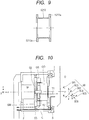
- the flanges 5211a and 5212a are joined together by an elastically deformable portion 5213 cylindrical in shape, and are united into a cross-sectional shape such as shown in FIG. 9 .
- the torque detection apparatus 52 configured as illustrated in FIGS. 7 to 9 is incorporated into the joint driving apparatus (72) as shown in FIG. 4 . That is, the flange 5211a of the torque detection apparatus 52 is fixed to the holding member 56 of the driving unit 80 and the flange 5212a is fixed to the inner surface of the housing unit on the side of the first link 62.
- a torque sensor (52s: not shown) made up of an optical sensor, magnetic sensor, or the like is placed, for example, at an appropriate location on an inner surface (or outer surface) of the elastically deformable portion 5213 so as to be able to detect torsion of the elastically deformable portion 5213 or relative displacement of the flanges 5211a and 5212a.
- the torque detection apparatus 52 is made up of the cylindrical elastic body 521, fixed at one end to the holding member 56 of the driving unit 80 as with the first embodiment, and fixed at the other end to the inner surface of the housing unit 55 on the side of the first link 62.
- the rest of the configuration of the joint driving apparatus (72) is similar to the first embodiment ( FIG. 2 ).
- the present embodiment can measure torque (rotational moment around Z axis shown in FIG. 2 ) by measuring a torsional deformation amount (or distortion amount) of the cylindrical elastic body 521 (elastically deformable portion 5213). Consequently, as with the first embodiment, joint driving torque can be detected accurately without being affected by cross-axis interference (crosstalk).
- the cylindrical elastic body 521 (elastically deformable portion 5213) of the torque detection apparatus 52 is fixed at one end is to the base (on the side of the link 62) of the housing unit 55 which is hardly deformed by cross-axis forces. This allows joint driving torque to be detected accurately without being affected by cross-axis interference (crosstalk).
- the present embodiment can simplify the structure of the torque detection apparatus 52, reduce the size and weight of the torque detection apparatus 52, and reduce the production cost of the torque detection apparatus 52.
- the elastic body 521 (elastically deformable portion 5213) of the torque detection apparatus 52 into a cylindrical shape, the torque detection apparatus 52 can be mounted using space around the rotary drive source 51 of the driving unit 80 in the joint driving apparatus (72).
- the elastic body 521 of the torque detection apparatus 52 can be configured to have a relatively large size and it is likely that an inexpensive torque sensor with a not very high resolution can be used to detect the deformation of the elastic body 521.
- Embodiment(s) of the present invention can also be realized by a computer of a system or apparatus that reads out and executes computer executable instructions (e.g., one or more programs) recorded on a storage medium (which may also be referred to more fully as a 'non-transitory computer-readable storage medium') to perform the functions of one or more of the above-described embodiment(s) and/or that includes one or more circuits (e.g., application specific integrated circuit (ASIC)) for performing the functions of one or more of the above-described embodiment(s), and by a method performed by the computer of the system or apparatus by, for example, reading out and executing the computer executable instructions from the storage medium to perform the functions of one or more of the above-described embodiment(s) and/or controlling the one or more circuits to perform the functions of one or more of the above-described embodiment(s).
- computer executable instructions e.g., one or more programs
- a storage medium which may also be referred to more fully as
- the computer may comprise one or more processors (e.g., central processing unit (CPU), micro processing unit (MPU)) and may include a network of separate computers or separate processors to read out and execute the computer executable instructions.
- the computer executable instructions may be provided to the computer, for example, from a network or the storage medium.
- the storage medium may include, for example, one or more of a hard disk, a random-access memory (RAM), a read only memory (ROM), a storage of distributed computing systems, an optical disk (such as a compact disc (CD), digital versatile disc (DVD), or Blu-ray Disc (BD)TM), a flash memory device, a memory card, and the like.
- a joint driving apparatus includes a housing unit fixed to a first link; a bearing mounted in the housing unit and adapted to rotatably support a second link; a driving unit housed in the housing unit and adapted to rotationally drive the second link; a supporting unit installed between the driving unit and the housing unit and adapted to support the driving unit on the housing unit; and a sensor adapted to detect torque generated on the supporting unit.
Landscapes
- Engineering & Computer Science (AREA)
- Robotics (AREA)
- Mechanical Engineering (AREA)
- Human Computer Interaction (AREA)
- Manipulator (AREA)
Description
- The present invention relates to a joint driving apparatus according to the preamble of
claim 1 as well as to a robot apparatus equipped with the driving apparatus and to a manufacturing method using the robot. - In recent years, articuleted robot manipulators have been finding increasingly wider uses and expanding their application to areas, such as collaborative work with humans and assembly work in a factory, in which robots are required to perform flexible movements. A stable and wide-band force control function is required of such a robot apparatus to follow external forces. Thus, there is demand to construct a control system based on joint-level torque control (torque servo) instead of a motion control system based on joint position control (position servo) widely used conventionally. The torque control requires a torque detection unit capable of accurately detecting torque which is output from joints of a robot arm.
- As this type of robot apparatus, for example, a multi-joint robot is known which is made up of plural links coupled by plural joint drive shafts. Such a multi-joint robot arm is configured such that forces acting on a member on an end side accumulate and act on a base member (base or mount). In order to improve responsiveness and mobility of the robot, it is necessary to make the entire robot compact and lightweight. For that, it is necessary to reduce the size and weight of a drive mechanism.
- Conventionally, regarding this type of joint driving apparatus, a configuration is known in which a torque detection apparatus adapted to measure output torque of the joint via a bearing adapted to rotatably support an output link is installed between an output shaft (final stage) of the joint driving apparatus, including a motor and a reduction mechanism, and a drive shaft of an output link. Generally, this type of torque detection apparatus is made up of a strain gage or an elastic member adapted to deform according to applied torque and a sensor device adapted to detect a deformation amount or distortion amount of the elastic member, for example, optically or magnetically.
- For example, a robot arm equipped with a torque sensor is disclosed in "A. Albu-Schaeffer, S. Haddadin, Ch. Ott, A. Stemmer, T. Wimboeck, G. Hirzinger, "The DLR lightweight robot: design and control concepts for robots in human environments", Industrial Robot: An International Journal, Vol.34, Iss: 5, pp.376 - 385 (2007)" (hereinafter, referred to as an article by A. Albu-Schaeffer et al.). The robot arm disclosed in the article by A. Albu-Schaeffer et al. includes an inner ring coupled to a shaft driven by a servomotor via strain wave gearing, an outer ring coupled to a first member of the robot arm, and a torque sensor adapted to measure torque, i.e., rotational torque between the inner ring and outer ring. With the robot arm disclosed in the article by A. Albu-Schaeffer et al., relative displacement produced between the inner ring and outer ring when torque acts around a rotating shaft of a first member is detected as distortion of the elastic member of the torque sensor, thereby measuring the rotational torque acting on the first member.
- However, in the configuration described in the article by A. Albu-Schaeffer et al., the torque sensor rotates together with a measuring object, causing, for example, a sensor cable attached to the torque sensor to deform along with motion of the drive shaft. Consequently, there is a problem in that when a reaction force from the sensor cable cannot be ignored, such as when a robot joint has a large operation angle, it is difficult to detect torque accurately. Also, with the configuration in the article by A. Albu-Schaeffer et al., a cable routing mechanism tends to become complicated, and it is not easy to ensure durability of the sensor cable.
- Also, as a torque detection apparatus for a drive system of a sphere tire adapted to move a robot apparatus, a configuration is proposed, for example, in
JP 2012-047460 A JP 2012-047460 A - However, in the configuration described in
JP 2012-047460 A -
JP 2012-047460 A JP 2012-047460 A -
JP 4 273335 B2 claim 1. -
US 5 155 423 A shows another joint driving apparatus according to the prior art. - Further, a general joint driving apparatus configuration is described in the professional article of Bong-Seok Kim ET AL: "Development of a Joint Torque Sensor Fully Integrated with an Actuator" (see Proc. of Int. Conf. on Control, Automation and Systems, 5 June 2005, pages 1679 to 1683).
- It is the object of the present invention to further develop a joint driving apparatus according to the preamble of
claim 1 such that a sturdy and compact configuration for the joint driving apparatus is provided. Furthermore, it is object of the present invention to provide a manufacturing method of an article using a robot comprising a plurality of the joint driving apparatuses. - The object of the present invention is achieved by a joint driving apparatus having the features of
claim 1 and a manufacturing method having the features of claim 12. - Further advantageous developments of the present invention are defined in the dependent claims.
- It is an advantage of the present invention to allow a joint driving apparatus of a robot apparatus to measure joint driving torque with high accuracy and perform joint torque control accurately and reliably using a simple, inexpensive, small, lightweight and sturdy configuration without being affected by cross-axis disturbance forces.
- According to another advantage of the present invention, the torque sensor is installed between the driving unit and the housing unit to detect torque produced on the supporting unit adapted to support the driving unit on the housing unit. The torque sensor can be fixed to the first link (fixed link), eliminating the need to route sensor cables for supplying power to the torque sensor and exchanging signals. This makes the configuration of the entire driving mechanism simple and compact, allowing the entire robot apparatus to be reduced in weight. Also, deformation of the sensor cable due to rotational motion of the joint driving apparatus can be inhibited, which enables preventing deterioration of the sensor cable as well as reduction of torque detection accuracy caused by deformation resistance of the sensor cable.
- Also, the joint driving apparatus according to the present invention is configured to support components of the forces acting on the second link (output link) excluding the rotational torque of a desired measurement object, using the bearing and housing unit. Therefore, cross-axis force (disturbance force) components other than the rotational torque to be detected do not act on the torque sensor adapted to detect the torque occurring on the supporting unit. This eliminates the need to install an additional support mechanism to support the torque sensor and driving unit, enables configuring the entire joint driving apparatus to be simple and compact, and thus makes it easy to reduce the size and weight of the entire joint driving apparatus and ensure rigidity of the driving apparatus. Thus, the present invention can reduce the size and weight of the entire robot apparatus which uses the joint driving apparatus and improve the responsiveness and agility of the robot apparatus.
- Further features of the present invention will become apparent from the following description of exemplary embodiments with reference to the attached drawings.
-
-
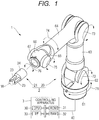
FIG. 1 is an explanatory diagram showing a schematic configuration of a robot apparatus capable of implementing the present invention. -
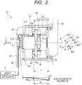
FIG. 2 is an explanatory diagram showing a structure of a joint driving apparatus according to a first embodiment of the present invention. -
FIG. 3 is a schematic diagram showing a sectional structure of a joint driving apparatus according to a second embodiment of the present invention. -
FIG. 4 is a schematic diagram showing a sectional structure of a joint driving apparatus according to a third embodiment of the present invention. -
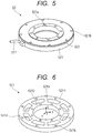
FIG. 5 is a perspective view showing an exemplary external shape of a torque sensor according to the first embodiment of the present invention. -
FIG. 6 is a perspective view showing an exemplary shape of an elastic body making up the torque sensor ofFIG. 5 . -
FIG. 7 is a perspective view showing an exemplary external shape of a torque sensor according to the third embodiment of the present invention. -
FIG. 8 is a perspective view showing an exemplary shape of an elastic body making up the torque sensor ofFIG. 7 . -
FIG. 9 is a sectional view showing an exemplary shape of an elastic body making up the torque sensor ofFIG. 7 . -
FIG. 10 is an explanatory diagram showing a transmission path of a force acting on an output link to a fixed link in the joint driving apparatus according to the present invention. -
FIG. 11 is an explanatory diagram showing a transmission path of a force acting on an output link to a fixed link in a conventional joint driving apparatus. -
FIG. 12 is an explanatory diagram schematically showing a transmission path of a force in the configurations ofFIGS. 10 and11 . - Exemplary embodiments of the present invention will be described below with reference to the accompanying drawings. Note that the embodiments described below are strictly exemplary and that those skilled in the art may change, for example, configuration details, as appropriate, within the scope of the present invention as defined by the appended claims. Also, the numeric values cited in the embodiments of the present invention are guidelines, and are not intended to limit the present invention.
- As shown in
FIG. 1 , arobot apparatus 1 includes arobot body 2 and acontrolling apparatus 3 adapted to control therobot body 2. Therobot body 2 is equipped with ahand 21 as an end effector in a front end portion of, for example, a six-axis vertical multi-joint robot arm (hereinafter, referred to as an arm) 20. Thearm 20 includes sevenlinks 61 to 67 and six joint driving apparatuses (driving apparatuses) 71 to 76 adapted to swingably or pivotably couple together thelinks 61 to 67. - The
hand 21 is supported by being attached to aforemost link 67 of thearm 20 and is configured such that motion (changes in position and orientation) or a force of thehand 21 will be adjusted by movement of thearm 20. Thehand 21 includes ahand body 24 andplural fingers 23 disposed movably with respect to thehand body 24 and configured to be able to grip a workpiece W. - The
controlling apparatus 3 includes aCPU 30 made up of a general purpose microprocessor and the like. TheCPU 30 controls movement of therobot body 2 by executing a robot control program stored, for example, in aROM 31. In so doing, aRAM 32 is used as a work area for program execution. Note that a program storage area of theROM 31 may be made up of a rewritable storage medium such as an EEPROM. In that case, the robot control program can be installed in theROM 31 or updated by supplying programs and control data from a flash memory or optical disk (not shown) . - Also, the
controlling apparatus 3 includes aninterface 33. Theinterface 33 is used to transmit control information to therobot body 2 and input detection information from the side of therobot body 2, where the control information is used to control the movement of thejoint driving apparatus 71 to 76 orhand 21 while the detection information is provided by a torque sensor (52s) described later. Also, theinterface 33 may include a network interface and the like. In that case, the robot control program can be installed in theROM 31 or updated using programs and control data received from a network. The network interface described above can also be used for communications with a robot teaching terminal (teaching pendant) and an off-line control terminal for use to create and edit the robot control program (neither terminal is shown) . -
FIG. 2 shows a sectional structure of thejoint driving apparatus 72 of thearm 20 as an example of thejoint driving apparatus 71 to 76. The configuration shown inFIG. 2 is also applicable to the otherjoint driving apparatus 71 to 76 of thearm 20. After-mentioned components of thejoint driving apparatus 72 are made of material such as metal, resin or the like which conform to the strength and rigidity required by specifications. - In
FIG. 2 , thejoint driving apparatus 72 includes a link 62 (first link) as a base-side member (fixed link) of the driving mechanism and a link 63 (second link) as an output side member (output link) of the driving mechanism. The link 62 (fixed link) and link 63 (output link) are configured to be rotatably coupled by abearing 54, which is a joint support mechanism supported on the housing unit 255. - The bearing 54 constrains rotational motion of the
link 63 relative to thelink 62 to allow only rotational motion around the drive shaft. Thebearing 54 has a function to support five forces/moments (FIG. 2 ), excluding rotational torque around the joint drive shaft, out of six-dimensional (translational) forces and moments acting on thelink 63. For example, a cross-roller bearing, which is widely used for robot joint mechanisms, can be used for thebearing 54, but this is not restrictive and other bearing members having similar functions are available for use. - In
FIG. 2 ,arrow 90 indicates a force acting on thelink 63. The force (90) acting on thelink 63 can be regarded as the composition of the following components. - Rotational torque (around z axis) 901 to be measured of the given joint
- Rotational moment component (x direction) 902 of cross-axis forces acting on the
link 63 - Rotational moment component (y direction) 903 of cross-axis forces acting on the
link 63 - Translational force component (x direction) 904 of cross-axis forces acting on the
link 63 - Translational force component (y direction) 905 of cross-axis forces acting on the
link 63 - Translational force component (z direction) 906 of cross-axis forces acting on the
link 63 - When a
rotary drive source 51 described below operates, the rotational torque (around z-axis) 901 is produced, controlling an orientation (angle) of thelink 63 relative to thelink 62. In so doing, the bearing 54 serving as a joint support mechanism restrains rotational motion of the joint around a joint axis (alternate long and short dash line) while supporting thecross-axis forces 902 to 906 described above. - The
joint driving apparatus 72 includes ahousing unit 55 configured to be approximately cylindrical in shape as a whole and adapted to house a drivingunit 80 made up of therotary drive source 51 and areduction mechanism 53. Thehousing unit 55 stores members needed to drive the joint as well as components needed to measure output torque. - According to the present embodiment, when a certain component is rigidly fixed to another component, the joining (fixing) region is referred to as a "fixing portion". For joining (fixing) in the "fixing portion", a technique such as screwing (details are not shown) is used. For example, a fixing
portion 551 is part of thehousing unit 55, which is fixed to the base-side link 62 of thejoint driving apparatus 72 via the fixingportion 551. - The
housing unit 55 according to the present embodiment includes the bearing 54 adapted to rotatably support the (second)link 63. Also, thehousing unit 55 houses the drivingunit 80 adapted to rotationally drive the (second)link 63. In particular, the drivingunit 80 is supported in thehousing unit 55 such that pivot (drive) shafts will coincide each other as follows. First, adrive shaft 51a of therotary drive source 51 of the drivingunit 80 is joined to aninput end 531 of thereduction mechanism 53. Also, thereduction mechanism 53 is made up of a strain wave gearing mechanism and the like, theinput end 531 and anoutput end 533 are placed coaxially, and a pivot shaft of thelink 63 is joined to theoutput end 533. - A supporting unit (532, 56, 52) adapted to support the driving
unit 80 on thehousing unit 55 are provided between the drivingunit 80 andhousing unit 55. The supporting unit includes a fixingportion 532 of thereduction mechanism 53, a holdingmember 56 of therotary drive source 51, and thetorque detection apparatus 52. The holdingmember 56 and fixingportion 532 are members generally annular in shape (flange-shaped) and it is assumed that recesses (open holes) approximately cylindrical in shape are formed in their front and back surfaces, as required, to accept a front end or rear end of therotary drive source 51 orreduction mechanism 53. - The
rotary drive source 51 is firmly fixed to the holdingmember 56, for example, by screwing (not shown) or the like, and the holdingmember 56 is firmly fixed to the fixingportion 532 of thereduction mechanism 53, for example, by screwing (not shown) or the like. Consequently, therotary drive source 51 andreduction mechanism 53 are integrally joined (firmly fixed) together, making up the drivingunit 80. - Then, the driving
unit 80 is joined (firmly fixed) to thehousing unit 55 via thetorque detection apparatus 52. Also, thesecond link 63, which is an output link, can pivot about thebearing 54 mounted in thehousing unit 55, and the drive shaft of thelink 63 is joined to theoutput end 533 of thereduction mechanism 53. - Thus, the driving
unit 80 is housed and supported in thehousing unit 55 by the supporting unit (the fixingportion 532 of thereduction mechanism 53, holdingmember 56 of therotary drive source 51 and torque detection apparatus 52) and thebearing 54 mounted in thehousing unit 55. That is, the drivingunit 80 is housed and supported at a center position of thehousing unit 55 by the supporting unit (the fixingportion 532 of thereduction mechanism 53, holdingmember 56 of therotary drive source 51 and torque detection apparatus 52) and thebearing 54 in such a way that a center line of thecylindrical housing unit 55 will match a drive axis. - Detailed configuration and arrangement of components housed in the
housing unit 55 as well as operating principles of driving of joints and measurement of torque will be described below. - The
rotary drive source 51, which generates a turning force (torque) to rotate a joint, is made up, for example, of an electric motor (servomotor). Therotary drive source 51 includes a rotary encoder for use to measure a motor rotation angle and a brake for use to hold the motor rotation angle (neither is shown). Also, therotary drive source 51 is connected with amotor wiring cable 572 to electrically drive the motor, input and output signals from/to the rotary encoder, and control on/off operation of the brake. - The
reduction mechanism 53 is made up of theinput end 531, theoutput end 533, and the fixingportion 532 of thereduction mechanism 53. A transmission mechanism of thereduction mechanism 53 is made up of, for example, a known strain wave gearing mechanism. According to the present embodiment, it is assumed that a reduction ratio of thereduction mechanism 53 is, for example, about 1:100. - The output of the
rotary drive source 51 rotationally drives theinput end 531 of thereduction mechanism 53, and thereduction mechanism 53 increases the torque generated by the rotary drive source (and simultaneously reduces the rotation angle at the reduction ratio) according to the reduction ratio and outputs the increased rotational torque through theoutput end 533. Consequently, the torque generated by therotary drive source 51 is increased to a level suitable to drive the joint, and thelink 63 constrained by thebearing 54 is actively driven by remaining rotational degrees of freedom (rotational freedom around the drive shaft) of the output torque of thereduction mechanism 53. - Here, the torque which can efficiently be produced by a small electric motor is usually far smaller than the torque needed to drive a joint. On the other hand, a rated rotational speed is much larger than the rotational speed required of the output shaft of the joint. Consequently, a reduction mechanism (53) with a high reduction ratio of about 1:30 to 1:200 is commonly used by most robots. A combination of such a small motor and a reduction mechanism (53) with a high reduction ratio has the advantage of making the configuration compact, but has a problem in that the reduction mechanism (53) causes a large torque loss due to friction and rotational resistance.
- Consequently, rotational torque which is output to an output stage of the joint cannot be grasped exactly by simply measuring motor torque, for example, by measuring a motor current proportional to the motor torque. Also, torque loss around a drive system including the reduction mechanism is caused mainly by non-linear physical phenomena such as friction, making precise modeling difficult and resulting in poor reproducibility. This makes the process of correcting the motor torque value detected via a motor current and thereby calculating actual output torque extremely difficult. Thus, if joints have to be controlled based on accurate torque detection, it is necessary to measure the output torque of the joint driving apparatus by installing a torque detection apparatus.
- As described above, the present embodiment adopts a configuration in which the
driving unit 80 is housed and supported in thehousing unit 55 by the supporting unit (the fixingportion 532 of thereduction mechanism 53, holdingmember 56 of therotary drive source 51 and torque detection apparatus 52) and thebearing 54 mounted in thehousing unit 55. Then, the present embodiment detects the torque generated on the supporting unit using thetorque detection apparatus 52 placed on the supporting unit. - As described above, the driving
unit 80 of thejoint driving apparatus 72 is made up of therotary drive source 51 andreduction mechanism 53. Then, as shown inFIG. 2 , the fixingportion 532 of thereduction mechanism 53 is joined to thetorque detection apparatus 52 via the holdingmember 56. Furthermore, thetorque detection apparatus 52, is joined (firmly fixed), for example, by screwing (details are not shown), to aflange portion 55a provided inside thehousing unit 55. - According to the present embodiment, the supporting unit (the fixing
portion 532 of thereduction mechanism 53, holdingmember 56 of therotary drive source 51 and torque detection apparatus 52) of the drivingunit 80 unites the drivingunit 80 and supports the drivingunit 80 in thehousing unit 55 in conjunction with thebearing 54. - A configuration example of the
torque detection apparatus 52 is shown inFIG. 5 . Thetorque detection apparatus 52 ofFIG. 5 is made up of an exterior member (cover) 522 and anelastic body 521. As illustrated, theexterior member 522 andelastic body 521 are generally annular in shape (ring-shaped) and provided withscrew holes member 56 of) the drivingunit 80 andflange portion 55a of thehousing unit 55. - Also, the
torque detection apparatus 52 includes asensor cable 571 for deriving output from atorque sensor 52s (FIG. 2 ). Thesensor cable 571 is connected with ajoint controller 57 placed inside acase 621 of the first link 62 (fixed link) as shown inFIG. 2 . Also, thejoint controller 57 is connected with therotary drive source 51 via themotor wiring cable 572. Thejoint controller 57 is connected to thecontrolling apparatus 3 via acable 40, and thetorque detection apparatus 52 transmits the output of thetorque sensor 52s to (theinterface 33 of) thecontrolling apparatus 3 and receives a drive signal used by thecontrolling apparatus 3 to control the drivingunit 80. - Now, consider operating the driving
unit 80 such that relative orientations of thelinks links FIG. 2 ) of thetorque detection apparatus 52, upon receiving a reaction force of the driving torque from the drivingunit 80, theelastic body 521 of thetorque detection apparatus 52 deforms according to magnitude of the reaction force. By detecting the deformation of theelastic body 521 using thetorque sensor 52s (FIG. 2 ), the torque generated on the supporting unit (the fixingportion 532 of thereduction mechanism 53, holdingmember 56 of therotary drive source 51 and torque detection apparatus 52) of the drivingunit 80 can be detected. Thetorque sensor 52s can be an optical sensor, magnetic sensor, or any other sensor device using any detection method. The torque value can be treated as driving torque (actual) for the joint driving apparatus (72) generated by the drivingunit 80. - The
elastic body 521 of thetorque detection apparatus 52 inFIG. 5 can have a configuration such as shown inFIG. 6 . Theelastic body 521 ofFIG. 6 includes aninner ring portion 5212, anouter ring portion 5211, and a spokelike elasticallydeformable portion 5213 configured to join together theinner ring portion 5212 andouter ring portion 5211. Theinner ring portion 5212 andouter ring portion 5211 are provided withscrew holes unit 80 andflange portion 55a of thehousing unit 55, respectively. That is, theelastic body 521 is fixed to the drivingunit 80 on its inner circumference side, and fixed to an inner surface of thehousing unit 55 on its outer circumference side. - The
torque sensor 52s (FIG. 2 ) is attached, for example, so as to detect a deformation amount of elasticallydeformable portion 5213. This enables measuring the torque (rotational moment around z axis inFIG. 2 ) generated on the supporting unit (the fixingportion 532 of thereduction mechanism 53, holdingmember 56 of therotary drive source 51 and torque detection apparatus 52) of the drivingunit 80 via thetorque sensor 52s (FIG. 2 ). - Upon receiving reaction of the torque (antitorque) which is output by the driving
unit 80 of thejoint driving apparatus 72, thetorque detection apparatus 52 configured as shown inFIGS. 5 and 6 can detect the driving torque of the drivingunit 80 via the antitorque. - That is, with the configuration of the present embodiment, a torque detection unit is not mounted on the side of the second link 63 (output link) configured to rotate relative to the first link 62 (fixed link). According to the present embodiment, even though the
torque detection apparatus 52 is placed on the side of the first link 62 (between thehousing unit 55 and driving unit 80), the torque which is output by the joint driving apparatus (72) can be measured. - With the configuration of the present embodiment, the sensor cable 571 (
FIG. 2 ) does not need to be laid across moving part of the joint driving apparatus (72). This eliminates the need to route thesensor cable 571, consequently, making the configuration of the entire driving mechanism simple and compact, and thus can reduce the weight of the entire robot apparatus. Also, there is no need to take into consideration the deformation of thesensor cable 571 resulting from the rotational motion of the joint driving apparatus (72), which enables preventing, for example, reduction of torque detection accuracy caused by deformation resistance of thesensor cable 571. Also, reduction of cable life caused by repeated deformation of thesensor cable 571 and sliding between the cable and cable supporting unit can be prevented and reliability of the robot apparatus can be improved greatly. - Also, according to the present embodiment, the driving torque of the driving
unit 80 of the joint driving apparatus (72) can be detected without being affected by disturbance caused by cross-axis forces. Here,FIG. 10 shows a transmission path of a force and moment acting on the link 63 (output link) of the joint driving apparatus (72) according to the present embodiment.FIG. 10 schematically shows a configuration equivalent to that of a joint driving apparatus (72) corresponding toFIG. 2 . InFIG. 10 , forces acting on various components and members corresponding to those inFIG. 2 are indicated by uppercase alphabetic characters while correspondence to reference numerals used above are shown in parentheses. - Also,
FIG. 12 shows transmission paths of forces among the members inFIG. 10 by extracting and indicating the transmission paths with arrows. A path T1 indicated by a broken line and a path T2 indicated by a solid line inFIG. 12 are equivalent to paths T1 and T2 inFIG. 11 , respectively. - In
FIGS. 10 and12 , reference character O denotes output of the output link (link 63), B denotes output of a joint support mechanism (the bearing 54), and GO denotes output of the driving unit (80:rotary drive source 51 and reduction mechanism 53). Also, GS denotes the fixing portion (532) of the driving unit (80), and GI denotes the input end (531) of the driving unit (80). Also, M denotes the rotary drive source (51), C denotes the housing unit (55), GM denotes a fixed member, F denotes a fixing portion to be joined to a fixed link (the link 62) of the housing, and TS denotes the torque detection apparatus (52). - In
FIGS. 10 and12 , when the robot apparatus performs motion, six-dimensional (translational) forces and moments (902 to 906) act on the output link (link 63) as described above inFIG. 2 . In the present embodiment, what one wants to measure with a torque detection apparatus is therotational torque 901 around the joint drive shaft. Cross-axis forces (902 to 906) are disturbance forces which will cause crosstalk for the torque detection apparatus. - As described above, the disturbance forces (five forces/moments (902 to 906) other than the rotational torque around the joint drive shaft) are supported by the bearing 54 (joint support mechanism). Thus, as shown in
FIG. 10 , cross-axis disturbance forces acting on output are supported by the housing unit via the bearing and transmitted to the fixed link (link 62) on the base side (path T2 inFIG. 10 ). - The force acting on the torque detection apparatus TS (52) via the driving unit 80 (
rotary drive source 51 and reduction mechanism 53) passes through the path T1 inFIG. 10 , and contains only the torque around the joint drive shaft without containing the disturbance forces. InFIG. 12 , in particular, the joint driving torque (TS-1) according to the present embodiment is transmitted as indicated by a broken line, passes through a path TS-3 (which corresponds to the torque detection apparatus TS ofFIG. 10 ), and is transmitted to the housing unit (C). The path (T1: broken line) is separated from the path (T2: solid line) of cross-axis disturbance forces, and the torque detection apparatus TS (FIG. 10 ; 52) is not affected by the cross-axis disturbance forces. - Now, in comparison with the present embodiment, transmissions of forces on a conventional joint driving apparatus are shown in
FIG. 11 . InFIG. 11 , components and forces are denoted by the same alphabetic symbols as the corresponding components and forces inFIG. 10 . - In the joint driving apparatus of
FIG. 11 , the torque detection apparatus TS is placed between the fixed link (F) and housings (C). Therefore, the joint driving apparatus ofFIG. 11 is configured such that cross-axis forces (path T2) act directly on the torque detection apparatus TS together with the torque (path T1) around the joint drive shaft to be detected. Consequently, in the configuration ofFIG. 11 , the cross-axis forces cause increased crosstalk, making accurate torque detection difficult. - For example, in
FIG. 12 , a path TS-2, which corresponds to the torque detection apparatus TS ofFIG. 11 , is shared by the torque (broken line) around the joint drive shaft and crosstalk (solid line) caused by cross-axis forces. That is, with the conventional configuration ofFIG. 11 , the torque detection apparatus TS cannot detect the torque (broken line) around the joint drive shaft to be detected, by separating the torque from the crosstalk (solid line) caused by cross-axis forces. - On the other hand, as shown in
FIGS. 10 and12 , the joint driving apparatus according to the present embodiment, which is configured such that cross-axis disturbance forces will not act on the torque detection apparatus (TS; 52), can accurately detect joint driving torque without being affected by cross-axis interference and crosstalk. Furthermore, the configuration of the present embodiment does not need an additional support mechanism to support the torque sensor and driving unit compared to the conventional technique (see, for example,JP 2012-047460 A - Now, the extent of cross-axis interference on the joint driving apparatus according to the present embodiment will be described by citing results obtained through calculations conducted based on concrete numeric values. Here, the deformation amount by which the
elastic body 521 of thetorque detection apparatus 52 is deformed by the output torque of the joint and the deformation amount by which the housing unit is deformed by cross-axis forces are calculated and compared with each other. - It is assumed that this calculation example is applicable to a small vertical multi-joint robot about 2 kg in transportable mass. Torsional rigidity K of the
elastic body 521 of thetorque detection apparatus 52 in a torque measurement direction (z-axis direction inFIG. 2 ) is about 20,000 Nm/rad (sufficiently high compared to the rigidity of the reduction mechanism). Thetorque detection apparatus 52 measures torque by measuring the deformation amount of theinner ring portion 5212 with respect to theouter ring portion 5211 of the elastic body 521 (FIG. 6 ) using the torque sensor (52s). - The torque sensor (52s) made up of a displacement measurement sensor, which can be an optical, magnetic, or any other sensor, is mounted, for example, within a circumference (or circular arc) with a radius of R = 30 mm around the
elastic body 521. - Here, a maximum value P of the translational force acting on the joint driving apparatus (72) of
FIG. 2 is about 300 N in the x direction when pushing operation and acceleration and deceleration motions of the robot are taken into consideration. Likewise, the torque T acting on the joint is about 50 Nm. Also, inFIG. 2 , outside diameter D of the housing unit is 90 mm, inside diameter d of the housing is 85 mm, and material is an aluminum alloy (modulus of longitudinal elasticity E = 90 Gpa). Also, a distance L from the bearing 54 supporting the joint to an installation location of thetorque detection apparatus 52 is 30 mm. - At this time, the deformation amount dXT of the inner ring which is output by the
torque sensor 52s when the joint is outputting rated torque is given by Expression (1) below.
- Here, if the housing unit is modeled as a beam having a simple cylindrical section, the geometric moment of inertia of the beam is given by Expression (2) below.

- Thus, a deformation amount dXdis of the displacement detecting unit of the
torque sensor 52s caused by the maximum value P of cross-axis forces is given by Expression (3) below.
- As described above, it can be seen that with the configuration of the present embodiment, there is no less than 3000-times difference between the deformation amount by which the elastic body of the sensor is deformed by torque measurement and the deformation amount by which the elastic body is deformed by cross-axis disturbance forces. That is, the present embodiment can detect the joint driving torque by being rarely affected by crosstalk caused by cross-axis forces and accurately detect the joint driving torque without being affected by the crosstalk caused by the cross-axis forces.
- Note that the numeric values shown above are only exemplary in the present embodiment, and are not intended to limit the present invention in any way. Also, according to the present embodiment, a six-axis vertical multi-joint robot arm is used as the
arm 20, but the number of axes can be changed as appropriate according to uses and purposes. For example, the configuration of the joint driving apparatus described above can also be applied easily to joints of a parallel-link robot arm. Also, although thelinks 61 to 67 of thearm 20 inFIG. 1 are fixed in length, for example, extendable links using linear actuators may be adopted as well. - Also, although in the present embodiment, a cross-roller bearing which can implement a desired support function by means of a single mechanism is used as the bearing 54 (joint support mechanism), concrete configuration of the support mechanism is not limited to this. For example, plural angular bearings may be used or a joint support function may be implemented by combining bearing mechanisms of other forms. Furthermore, although a ratio of 1:100 has been shown as a reduction ratio of the
reduction mechanism 53, this is not restrictive and the reduction ratio of thereduction mechanism 53 may be set to any desired value. - Also, in the present embodiment, the driving unit (joint torque generating mechanism) 80 is configured by combining the
rotary drive source 51 such as an electric motor and thereduction mechanism 53 such as a strain wave gearing mechanism. However, the form of thejoint driving unit 80 is not limited to this, and, for example, a direct drive motor without a reduction mechanism may be used. Also, the energy source is not limited to an electrically operated driving mechanism, and a hydraulic or other fluid drive mechanism can implement a member arrangement similar to the one described above. - As shown in
FIG. 2 and Expression (3), it can be seen that the deformation amount of theouter ring portion 5211 of theelastic body 521 of thetorque detection apparatus 52 is affected greatly by the distance L between the installation location on thehousing unit 55 and thebearing 54 supporting the joint. Thus, if the torque detection apparatus 52 (elastic body 521) can be placed close to thebearing 54, an amount of cross-axis interference can be reduced further. - For example, as shown in
FIG. 3 , the flange portion 55b used to attach the torque detection apparatus 52 (elastic body 521) to thehousing unit 55 is placed closer to the bearing (joint support mechanism) 54 than the flange portion (55a) inFIG. 2 . Then, the torque detection apparatus 52 (elastic body 521) is mounted between the fixingportion 532 of thereduction mechanism 53 and the flange portion 55b. The rest of the configuration is similar toFIG. 2 . - In the configuration of
FIG. 3 , the torque detection apparatus 52 (elastic body 521) is placed between the fixing portion of the driving unit 80 (fixingportion 532 of the reduction mechanism 53) and thehousing unit 55 as with the first embodiment. However, inFIG. 3 , the torque detection apparatus 52 (elastic body 521) is attached to thehousing unit 55 at a location between the bearing (joint support mechanism) 54 and drivingunit 80, and more particularly, at a location closer to thebearing 54 supporting thesecond link 63. - In this way, by attaching the
torque detection apparatus 52 to thehousing unit 55 at a location closer to thebearing 54 and carrying out detection at a location closer to thebearing 54, the amount of cross-axis interference can be reduced further, enabling more accurate torque detection. - In the embodiments described above, the
elastic body 521 of thetorque detection apparatus 52 has been shown as having an annular shape (ring shape) by example. However, the joint driving apparatus (72) may be configured as shown inFIG. 4 using thetorque detection apparatus 52 which employs an elastic body of different shapes such as shown inFIGS. 7 to 9 . - The present embodiment uses a
torque detection apparatus 52 such as shown inFIG. 7 . Thetorque detection apparatus 52 includes anelastic body 521, an exterior member (cover) 522 configured to protect theelastic body 521, and asensor cable 571 and has an approximately cylindrical shape as a whole. - As shown in
FIG. 8 , theelastic body 521 includes aflange 5211a serving as a first fixing portion and aflange 5212a serving as a second fixing portion. Theflanges deformable portion 5213 cylindrical in shape, and are united into a cross-sectional shape such as shown inFIG. 9 . - The
torque detection apparatus 52 configured as illustrated inFIGS. 7 to 9 is incorporated into the joint driving apparatus (72) as shown inFIG. 4 . That is, theflange 5211a of thetorque detection apparatus 52 is fixed to the holdingmember 56 of the drivingunit 80 and theflange 5212a is fixed to the inner surface of the housing unit on the side of thefirst link 62. A torque sensor (52s: not shown) made up of an optical sensor, magnetic sensor, or the like is placed, for example, at an appropriate location on an inner surface (or outer surface) of the elasticallydeformable portion 5213 so as to be able to detect torsion of the elasticallydeformable portion 5213 or relative displacement of theflanges - As described above, the
torque detection apparatus 52 is made up of the cylindricalelastic body 521, fixed at one end to the holdingmember 56 of the drivingunit 80 as with the first embodiment, and fixed at the other end to the inner surface of thehousing unit 55 on the side of thefirst link 62. The rest of the configuration of the joint driving apparatus (72) is similar to the first embodiment (FIG. 2 ). - The present embodiment can measure torque (rotational moment around Z axis shown in
FIG. 2 ) by measuring a torsional deformation amount (or distortion amount) of the cylindrical elastic body 521 (elastically deformable portion 5213). Consequently, as with the first embodiment, joint driving torque can be detected accurately without being affected by cross-axis interference (crosstalk). In particular, according to the present embodiment, the cylindrical elastic body 521 (elastically deformable portion 5213) of thetorque detection apparatus 52 is fixed at one end is to the base (on the side of the link 62) of thehousing unit 55 which is hardly deformed by cross-axis forces. This allows joint driving torque to be detected accurately without being affected by cross-axis interference (crosstalk). - Also, the present embodiment can simplify the structure of the
torque detection apparatus 52, reduce the size and weight of thetorque detection apparatus 52, and reduce the production cost of thetorque detection apparatus 52. In particular, by configuring the elastic body 521 (elastically deformable portion 5213) of thetorque detection apparatus 52 into a cylindrical shape, thetorque detection apparatus 52 can be mounted using space around therotary drive source 51 of the drivingunit 80 in the joint driving apparatus (72). Also, theelastic body 521 of thetorque detection apparatus 52 can be configured to have a relatively large size and it is likely that an inexpensive torque sensor with a not very high resolution can be used to detect the deformation of theelastic body 521. - Embodiment(s) of the present invention can also be realized by a computer of a system or apparatus that reads out and executes computer executable instructions (e.g., one or more programs) recorded on a storage medium (which may also be referred to more fully as a 'non-transitory computer-readable storage medium') to perform the functions of one or more of the above-described embodiment(s) and/or that includes one or more circuits (e.g., application specific integrated circuit (ASIC)) for performing the functions of one or more of the above-described embodiment(s), and by a method performed by the computer of the system or apparatus by, for example, reading out and executing the computer executable instructions from the storage medium to perform the functions of one or more of the above-described embodiment(s) and/or controlling the one or more circuits to perform the functions of one or more of the above-described embodiment(s). The computer may comprise one or more processors (e.g., central processing unit (CPU), micro processing unit (MPU)) and may include a network of separate computers or separate processors to read out and execute the computer executable instructions. The computer executable instructions may be provided to the computer, for example, from a network or the storage medium. The storage medium may include, for example, one or more of a hard disk, a random-access memory (RAM), a read only memory (ROM), a storage of distributed computing systems, an optical disk (such as a compact disc (CD), digital versatile disc (DVD), or Blu-ray Disc (BD)™), a flash memory device, a memory card, and the like.
- While the present invention has been described with reference to exemplary embodiments, it is to be understood that the invention is not limited to the disclosed exemplary embodiments, i.e. the scope of the present invention as defined by the following claims shall encompass all such modifications and equivalent structures and functions.
- The present invention allows a joint driving apparatus of a robot apparatus to measure joint driving torque with high accuracy and perform joint torque control accurately and reliably using a simple, inexpensive, small, lightweight and sturdy configuration without being affected by cross-axis disturbance forces. A joint driving apparatus includes a housing unit fixed to a first link; a bearing mounted in the housing unit and adapted to rotatably support a second link; a driving unit housed in the housing unit and adapted to rotationally drive the second link; a supporting unit installed between the driving unit and the housing unit and adapted to support the driving unit on the housing unit; and a sensor adapted to detect torque generated on the supporting unit.
Claims (12)
- A joint driving apparatus (72) comprising:a housing unit (55) provided to a first link (62);a driving unit (80) housed in the housing unit (55) and adapted to rotationally drive a second link (63), an output end (533) of the driving unit (80) being connected to the second link (63);a bearing (54) provided in the housing unit (55), the bearing (54) being adapted to rotatably support the second link (63) and configured to couple the second link (63) to the housing unit (55); anda supporting unit comprising a holding member (56), being configured to couple the driving unit (80) to the housing unit (55) and configured to support the driving unit (80) on the housing unit (55), the supporting unit comprising a torque detection apparatus (52) comprising an elastic body (521) configured to deform to a rotating direction of the second link (63) and a sensor (52s) configured to detect torque generated on the supporting unit, whereinthe driving unit (80) further comprises a driving source (51) and a reduction mechanism (53),characterized in thatthe holding member (56) is provided between the driving source (51) and the reduction mechanism (53), andthe supporting unit is provided within the housing unit (55) and between the driving unit (80) and the housing unit (55), and the supporting unit couples the driving unit (80) to the housing unit (55) via the torque detection apparatus (52) being joined at one end to the holding member (56)and at the other end to the housing unit (55).
- The joint driving apparatus (72) according to claim 1, wherein the sensor (52s) measures a torque based on deformation of the elastic body (521).
- The joint driving apparatus (72) according to claim 1 or 2, wherein
the elastic body (521) deforms when the driving unit (80) moves in a direction of rotating the second link (63) relative to the housing unit (55). - The joint driving apparatus (72) according to any one of claims 1 to 3, wherein the elastic body (521) is configured to be annular in shape and adapted to support the driving unit (80).
- The joint driving apparatus (72) according to any one of claims 1 to 4, wherein an inner circumference side of the elastic body (521) is provided to the driving unit (80); and
an outer circumference side of the elastic body (521) is provided to an inner surface of the housing unit (55). - The joint driving apparatus (72) according to claim 5, wherein the outer circumference side of the elastic body (521) is provided to that position on the inner surface of the housing unit (55) which is close to the bearing (54) adapted to support the second link.
- The joint driving apparatus (72) according to any one of claims 1 to 6, wherein the elastic body (521) is configured to be cylindrical in shape and adapted to support the driving unit (80).
- The joint driving apparatus (72) according to claim 7, wherein the cylindrical elastic body (521) is provided at one end to the driving unit (80) and provided at another end to an inner surface of the housing unit (55) on a side of the first link (62).
- The joint driving apparatus (72) according to any one of claims 1 to 8, wherein the sensor (52s) is a sensor device adapted to detect a deformation amount of the elastic body (521).
- The joint driving apparatus (72) according to any one of claims 1 to 9, wherein the reduction mechanism (53) is adapted to decelerate rotation of the rotary drive source (51).
- A robot apparatus comprising a plurality of joint driving apparatuses (72) each driving each of a plurality of joints of a robot arm (20), wherein at least one of the plurality of joint driving apparatuses (72) is provided according to any one of claims 1 to 10.
- A manufacturing method of an article characterized by manufacturing the article using the robot apparatus according to claim 11.
Applications Claiming Priority (1)
| Application Number | Priority Date | Filing Date | Title |
|---|---|---|---|
| JP2015050123A JP6632204B2 (en) | 2015-03-13 | 2015-03-13 | Driving device, robot device, and article manufacturing method |
Publications (3)
| Publication Number | Publication Date |
|---|---|
| EP3067164A2 EP3067164A2 (en) | 2016-09-14 |
| EP3067164A3 EP3067164A3 (en) | 2017-01-18 |
| EP3067164B1 true EP3067164B1 (en) | 2021-07-28 |
Family
ID=55661145
Family Applications (1)
| Application Number | Title | Priority Date | Filing Date |
|---|---|---|---|
| EP16159566.5A Active EP3067164B1 (en) | 2015-03-13 | 2016-03-10 | Joint driving apparatus and robot apparatus |
Country Status (4)
| Country | Link |
|---|---|
| US (1) | US10335959B2 (en) |
| EP (1) | EP3067164B1 (en) |
| JP (1) | JP6632204B2 (en) |
| CN (1) | CN105965504B (en) |
Families Citing this family (33)
| Publication number | Priority date | Publication date | Assignee | Title |
|---|---|---|---|---|
| GB2540756B (en) | 2015-07-22 | 2021-03-31 | Cmr Surgical Ltd | Gear packaging for robot arms |
| US10926404B2 (en) * | 2015-07-22 | 2021-02-23 | Cmr Surgical Limited | Gear packaging for robot arms |
| GB2541369B (en) | 2015-07-22 | 2021-03-31 | Cmr Surgical Ltd | Drive mechanisms for robot arms |
| GB2540757B (en) * | 2015-07-22 | 2021-03-31 | Cmr Surgical Ltd | Torque sensors |
| JP6752576B2 (en) * | 2016-01-13 | 2020-09-09 | キヤノン株式会社 | Drive mechanism, robot device, control method of drive mechanism, control method of robot device, manufacturing method of article, control program, recording medium, and support member |
| JP6501746B2 (en) * | 2016-10-07 | 2019-04-17 | キヤノン株式会社 | Displacement measuring device, robot, robot arm and method of manufacturing article |
| JP2018075674A (en) * | 2016-11-10 | 2018-05-17 | ソニー株式会社 | Joint driving actuator |
| US10444098B2 (en) | 2017-04-10 | 2019-10-15 | Fanuc Corporation | Torque sensor and robot |
| JP2018202504A (en) | 2017-05-31 | 2018-12-27 | ソニー株式会社 | Medical support arm system, method of controlling medical support arm, and control device of medical support arm |
| EP3418007A1 (en) * | 2017-06-19 | 2018-12-26 | ABB Schweiz AG | Method of determining a joint torque in a joint of an articulated industrial robot |
| CA176118S (en) * | 2017-07-28 | 2018-09-20 | Genesis Robotics Llp | Robotic arm |
| CN107511849B (en) * | 2017-08-31 | 2024-03-01 | 广州泰行智能科技有限公司 | Fixing structure of cable |
| CN107435720A (en) * | 2017-09-07 | 2017-12-05 | 吴烈 | Driving joint, power arm and Versatile Construction Machinery |
| WO2019083302A1 (en) * | 2017-10-25 | 2019-05-02 | 고려대학교 산학협력단 | Joint torque sensor and robot joint unit including same |
| KR102003906B1 (en) * | 2017-10-25 | 2019-07-25 | 고려대학교 산학협력단 | Robot articulation unit having joint torque sensor |
| WO2019087904A1 (en) * | 2017-11-01 | 2019-05-09 | ソニー株式会社 | Surgical arm system and surgical arm control system |
| USD890238S1 (en) * | 2018-03-02 | 2020-07-14 | Abb Schweiz Ag | Joint for an industrial robot |
| DE102018107142A1 (en) * | 2018-03-26 | 2019-09-26 | M-Robot OHG | manipulator device |
| USD883351S1 (en) * | 2018-05-10 | 2020-05-05 | Robotiq Inc. | Robotic end effector |
| DE102018213452A1 (en) * | 2018-08-09 | 2020-02-13 | Kuka Deutschland Gmbh | Robotic arm with at least one joint torque sensor |
| CN108920880B (en) * | 2018-08-14 | 2023-06-09 | 合肥哈工图南智控机器人有限公司 | Motor and speed reducer type selection method of intelligent driving unit |
| US11045950B2 (en) * | 2018-11-02 | 2021-06-29 | Canon Kabushiki Kaisha | Driving device and detecting device |
| JP2020116693A (en) * | 2019-01-24 | 2020-08-06 | キヤノン株式会社 | Joint device, robot arm, torque and rotation angle detection device, and article manufacturing method |
| EP3927496A4 (en) * | 2019-02-20 | 2022-06-29 | Harmonic Bionics, Inc. | Actuator for physical therapy |
| JP7319105B2 (en) * | 2019-06-27 | 2023-08-01 | ファナック株式会社 | Rotary axis structure and robot |
| DE102019119658A1 (en) * | 2019-07-19 | 2021-01-21 | Pilz Gmbh & Co. Kg | Cycloid gear with torque detection device |
| JP7303702B2 (en) * | 2019-08-21 | 2023-07-05 | 住友重機械工業株式会社 | robot |
| DE112021001706T5 (en) * | 2020-03-18 | 2023-01-12 | Fanuc Corporation | ROTARY SHAFT STRUCTURE WITH FORCE SENSOR AND ROBOT |
| CN116963880A (en) * | 2021-03-03 | 2023-10-27 | 住友重机械工业株式会社 | Connecting device and manipulator |
| CN113183148A (en) * | 2021-03-31 | 2021-07-30 | 成都飞机工业(集团)有限责任公司 | Industrial robot singularity-avoiding end effector connecting device and singularity-avoiding method |
| US11541530B1 (en) | 2021-09-30 | 2023-01-03 | Harmonic Bionics, Inc. | Compliant mechanism for improving axial load sensing in robotic actuators |
| CN113618702B (en) * | 2021-10-12 | 2022-03-18 | 深圳市越疆科技有限公司 | Teleoperation manipulator and rocker arm structure thereof, teleoperation equipment |
| JP2023095023A (en) | 2021-12-24 | 2023-07-06 | キヤノン株式会社 | Robot, manufacturing method and distributed sensor |
Family Cites Families (22)
| Publication number | Priority date | Publication date | Assignee | Title |
|---|---|---|---|---|
| JPS582800B2 (en) * | 1979-02-28 | 1983-01-18 | 株式会社明電舎 | Actuation force detection device for manipulators, etc. |
| JPS6133892A (en) * | 1984-07-26 | 1986-02-17 | 株式会社東芝 | Method of measuring driving torque of joint of robot |
| JPS6150030A (en) * | 1984-08-18 | 1986-03-12 | Omron Tateisi Electronics Co | Thin type force detector |
| US5155423A (en) * | 1986-02-18 | 1992-10-13 | Robotics Research Corporation | Industrial robot with servo |
| JPS63185535U (en) * | 1987-05-21 | 1988-11-29 | ||
| JPH05223665A (en) * | 1992-02-18 | 1993-08-31 | Fujitsu Ltd | Torque detection part of motor |
| US5327790A (en) * | 1992-06-19 | 1994-07-12 | Massachusetts Institute Of Technology | Reaction sensing torque actuator |
| JP3324298B2 (en) * | 1994-10-19 | 2002-09-17 | 株式会社豊田中央研究所 | Manipulator control device |
| JP3644558B2 (en) * | 1995-11-02 | 2005-04-27 | 株式会社ハーモニック・ドライブ・システムズ | Torque detection mechanism of flexure meshing gear unit |
| JP3624374B2 (en) * | 2000-12-12 | 2005-03-02 | 独立行政法人産業技術総合研究所 | Force display device |
| JP4273335B2 (en) * | 2004-06-16 | 2009-06-03 | 独立行政法人産業技術総合研究所 | Robot arm |
| DE102007005894A1 (en) * | 2006-06-14 | 2007-12-20 | GIF Gesellschaft für Industrieforschung mbH | torque flange |
| JP4230500B2 (en) * | 2006-09-07 | 2009-02-25 | 豊田鉄工株式会社 | Load detection device |
| CN101539464B (en) * | 2009-04-17 | 2010-09-22 | 北京航空航天大学 | Elastic torsion shaft |
| JP5218524B2 (en) * | 2010-03-15 | 2013-06-26 | 株式会社安川電機 | Robot system and robot operation restriction method |
| JP2011209099A (en) | 2010-03-30 | 2011-10-20 | Sony Corp | Torque sensor and robot apparatus |
| JP2012047460A (en) | 2010-08-24 | 2012-03-08 | Sony Corp | Torque detection device and robot device |
| CN102494819A (en) * | 2011-11-29 | 2012-06-13 | 北京邮电大学 | Joint torque sensor based on elastic beam |
| DE102012202181A1 (en) | 2012-02-14 | 2013-08-29 | Kuka Roboter Gmbh | Method for determining a torque and industrial robots |
| KR101194313B1 (en) * | 2012-03-30 | 2012-10-26 | 한국기계연구원 | Driving modules with hollowness |
| US9293962B2 (en) * | 2012-03-30 | 2016-03-22 | Korea Institute Of Machinery & Materials | Hollow driving module |
| CN103711741B (en) * | 2013-12-17 | 2015-10-28 | 东南大学 | A kind of joint of robot rotating liquid cylinder pressure with moment of torsion and angle feed-back |
-
2015
- 2015-03-13 JP JP2015050123A patent/JP6632204B2/en active Active
-
2016
- 2016-03-08 CN CN201610128482.8A patent/CN105965504B/en active Active
- 2016-03-10 EP EP16159566.5A patent/EP3067164B1/en active Active
- 2016-03-11 US US15/067,686 patent/US10335959B2/en active Active
Non-Patent Citations (1)
| Title |
|---|
| None * |
Also Published As
| Publication number | Publication date |
|---|---|
| EP3067164A3 (en) | 2017-01-18 |
| US10335959B2 (en) | 2019-07-02 |
| CN105965504A (en) | 2016-09-28 |
| JP2016168647A (en) | 2016-09-23 |
| US20160263749A1 (en) | 2016-09-15 |
| CN105965504B (en) | 2020-11-20 |
| JP6632204B2 (en) | 2020-01-22 |
| EP3067164A2 (en) | 2016-09-14 |
Similar Documents
| Publication | Publication Date | Title |
|---|---|---|
| EP3067164B1 (en) | Joint driving apparatus and robot apparatus | |
| JP6332899B2 (en) | robot | |
| US10486309B2 (en) | Robot controlling method, robot apparatus, program, recording medium, and method for manufacturing assembly component | |
| US10239204B2 (en) | Method of controlling robot and robot | |
| WO2011117944A1 (en) | Force control robot | |
| JP6111562B2 (en) | robot | |
| EP3403774A1 (en) | Robot hand, robot apparatus, and control method for robot hand | |
| JP5897644B2 (en) | Robot control device | |
| US20120048628A1 (en) | Torque detection apparatus and robot apparatus | |
| US9950427B2 (en) | Robot, control apparatus, and robot system | |
| JP2010228028A (en) | Robot arm, contact detection method for robot arm, and device equipped with robot arm | |
| US20220016781A1 (en) | Method for Aligning a Robotic Arm | |
| CN212218476U (en) | Torque-controllable rotary driver and robot system | |
| US11141855B2 (en) | Robot system, method of controlling robot arm, recording medium, and method of manufacturing an article | |
| JP6998514B2 (en) | Robot control device | |
| US20190366537A1 (en) | Driving mechanism, robot apparatus, method for controlling driving mechanism, method of manufacturing an article using robot arm, and storage medium | |
| EP3448628B1 (en) | Control of a robot joint using two drives | |
| JP2019030923A (en) | Robot arm, robot device, and robot system | |
| Tsetserukou et al. | Design, control and evaluation of a whole-sensitive robot arm for physical human-robot interaction | |
| JP2020015146A (en) | Robot arm and robot device | |
| JP6036476B2 (en) | robot | |
| JP7414426B2 (en) | robot system | |
| WO2023243241A1 (en) | Force-controlled actuator | |
| JPH0717496A (en) | Attitude control mode of artificial satellite | |
| JP7082365B2 (en) | Parallel link robot |
Legal Events
| Date | Code | Title | Description |
|---|---|---|---|
| PUAI | Public reference made under article 153(3) epc to a published international application that has entered the european phase |
Free format text: ORIGINAL CODE: 0009012 |
|
| AK | Designated contracting states |
Kind code of ref document: A2 Designated state(s): AL AT BE BG CH CY CZ DE DK EE ES FI FR GB GR HR HU IE IS IT LI LT LU LV MC MK MT NL NO PL PT RO RS SE SI SK SM TR |
|
| AX | Request for extension of the european patent |
Extension state: BA ME |
|
| REG | Reference to a national code |
Ref country code: DE Ref legal event code: R079 Ref document number: 602016061174 Country of ref document: DE Free format text: PREVIOUS MAIN CLASS: B25J0009120000 Ipc: B25J0017020000 |
|
| PUAL | Search report despatched |
Free format text: ORIGINAL CODE: 0009013 |
|
| AK | Designated contracting states |
Kind code of ref document: A3 Designated state(s): AL AT BE BG CH CY CZ DE DK EE ES FI FR GB GR HR HU IE IS IT LI LT LU LV MC MK MT NL NO PL PT RO RS SE SI SK SM TR |
|
| AX | Request for extension of the european patent |
Extension state: BA ME |
|
| RIC1 | Information provided on ipc code assigned before grant |
Ipc: B25J 13/08 20060101ALI20161214BHEP Ipc: B25J 17/00 20060101ALI20161214BHEP Ipc: B25J 9/12 20060101ALI20161214BHEP Ipc: B25J 17/02 20060101AFI20161214BHEP |
|
| STAA | Information on the status of an ep patent application or granted ep patent |
Free format text: STATUS: REQUEST FOR EXAMINATION WAS MADE |
|
| 17P | Request for examination filed |
Effective date: 20170718 |
|
| RBV | Designated contracting states (corrected) |
Designated state(s): AL AT BE BG CH CY CZ DE DK EE ES FI FR GB GR HR HU IE IS IT LI LT LU LV MC MK MT NL NO PL PT RO RS SE SI SK SM TR |
|
| STAA | Information on the status of an ep patent application or granted ep patent |
Free format text: STATUS: EXAMINATION IS IN PROGRESS |
|
| 17Q | First examination report despatched |
Effective date: 20181214 |
|
| STAA | Information on the status of an ep patent application or granted ep patent |
Free format text: STATUS: EXAMINATION IS IN PROGRESS |
|
| GRAP | Despatch of communication of intention to grant a patent |
Free format text: ORIGINAL CODE: EPIDOSNIGR1 |
|
| STAA | Information on the status of an ep patent application or granted ep patent |
Free format text: STATUS: GRANT OF PATENT IS INTENDED |
|
| INTG | Intention to grant announced |
Effective date: 20210218 |
|
| RIN1 | Information on inventor provided before grant (corrected) |
Inventor name: OGATA, MASARU |
|
| GRAS | Grant fee paid |
Free format text: ORIGINAL CODE: EPIDOSNIGR3 |
|
| GRAA | (expected) grant |
Free format text: ORIGINAL CODE: 0009210 |
|
| STAA | Information on the status of an ep patent application or granted ep patent |
Free format text: STATUS: THE PATENT HAS BEEN GRANTED |
|
| AK | Designated contracting states |
Kind code of ref document: B1 Designated state(s): AL AT BE BG CH CY CZ DE DK EE ES FI FR GB GR HR HU IE IS IT LI LT LU LV MC MK MT NL NO PL PT RO RS SE SI SK SM TR |
|
| REG | Reference to a national code |
Ref country code: GB Ref legal event code: FG4D |
|
| REG | Reference to a national code |
Ref country code: CH Ref legal event code: EP |
|
| REG | Reference to a national code |
Ref country code: AT Ref legal event code: REF Ref document number: 1414306 Country of ref document: AT Kind code of ref document: T Effective date: 20210815 |
|
| REG | Reference to a national code |
Ref country code: IE Ref legal event code: FG4D |
|
| REG | Reference to a national code |
Ref country code: DE Ref legal event code: R096 Ref document number: 602016061174 Country of ref document: DE |
|
| REG | Reference to a national code |
Ref country code: LT Ref legal event code: MG9D |
|
| REG | Reference to a national code |
Ref country code: NL Ref legal event code: MP Effective date: 20210728 |
|
| REG | Reference to a national code |
Ref country code: AT Ref legal event code: MK05 Ref document number: 1414306 Country of ref document: AT Kind code of ref document: T Effective date: 20210728 |
|
| PG25 | Lapsed in a contracting state [announced via postgrant information from national office to epo] |
Ref country code: BG Free format text: LAPSE BECAUSE OF FAILURE TO SUBMIT A TRANSLATION OF THE DESCRIPTION OR TO PAY THE FEE WITHIN THE PRESCRIBED TIME-LIMIT Effective date: 20211028 Ref country code: AT Free format text: LAPSE BECAUSE OF FAILURE TO SUBMIT A TRANSLATION OF THE DESCRIPTION OR TO PAY THE FEE WITHIN THE PRESCRIBED TIME-LIMIT Effective date: 20210728 Ref country code: LT Free format text: LAPSE BECAUSE OF FAILURE TO SUBMIT A TRANSLATION OF THE DESCRIPTION OR TO PAY THE FEE WITHIN THE PRESCRIBED TIME-LIMIT Effective date: 20210728 Ref country code: FI Free format text: LAPSE BECAUSE OF FAILURE TO SUBMIT A TRANSLATION OF THE DESCRIPTION OR TO PAY THE FEE WITHIN THE PRESCRIBED TIME-LIMIT Effective date: 20210728 Ref country code: ES Free format text: LAPSE BECAUSE OF FAILURE TO SUBMIT A TRANSLATION OF THE DESCRIPTION OR TO PAY THE FEE WITHIN THE PRESCRIBED TIME-LIMIT Effective date: 20210728 Ref country code: PT Free format text: LAPSE BECAUSE OF FAILURE TO SUBMIT A TRANSLATION OF THE DESCRIPTION OR TO PAY THE FEE WITHIN THE PRESCRIBED TIME-LIMIT Effective date: 20211129 Ref country code: NO Free format text: LAPSE BECAUSE OF FAILURE TO SUBMIT A TRANSLATION OF THE DESCRIPTION OR TO PAY THE FEE WITHIN THE PRESCRIBED TIME-LIMIT Effective date: 20211028 Ref country code: NL Free format text: LAPSE BECAUSE OF FAILURE TO SUBMIT A TRANSLATION OF THE DESCRIPTION OR TO PAY THE FEE WITHIN THE PRESCRIBED TIME-LIMIT Effective date: 20210728 Ref country code: RS Free format text: LAPSE BECAUSE OF FAILURE TO SUBMIT A TRANSLATION OF THE DESCRIPTION OR TO PAY THE FEE WITHIN THE PRESCRIBED TIME-LIMIT Effective date: 20210728 Ref country code: SE Free format text: LAPSE BECAUSE OF FAILURE TO SUBMIT A TRANSLATION OF THE DESCRIPTION OR TO PAY THE FEE WITHIN THE PRESCRIBED TIME-LIMIT Effective date: 20210728 Ref country code: HR Free format text: LAPSE BECAUSE OF FAILURE TO SUBMIT A TRANSLATION OF THE DESCRIPTION OR TO PAY THE FEE WITHIN THE PRESCRIBED TIME-LIMIT Effective date: 20210728 |
|
| PG25 | Lapsed in a contracting state [announced via postgrant information from national office to epo] |
Ref country code: PL Free format text: LAPSE BECAUSE OF FAILURE TO SUBMIT A TRANSLATION OF THE DESCRIPTION OR TO PAY THE FEE WITHIN THE PRESCRIBED TIME-LIMIT Effective date: 20210728 Ref country code: LV Free format text: LAPSE BECAUSE OF FAILURE TO SUBMIT A TRANSLATION OF THE DESCRIPTION OR TO PAY THE FEE WITHIN THE PRESCRIBED TIME-LIMIT Effective date: 20210728 Ref country code: GR Free format text: LAPSE BECAUSE OF FAILURE TO SUBMIT A TRANSLATION OF THE DESCRIPTION OR TO PAY THE FEE WITHIN THE PRESCRIBED TIME-LIMIT Effective date: 20211029 |
|
| PG25 | Lapsed in a contracting state [announced via postgrant information from national office to epo] |
Ref country code: DK Free format text: LAPSE BECAUSE OF FAILURE TO SUBMIT A TRANSLATION OF THE DESCRIPTION OR TO PAY THE FEE WITHIN THE PRESCRIBED TIME-LIMIT Effective date: 20210728 |
|
| REG | Reference to a national code |
Ref country code: DE Ref legal event code: R097 Ref document number: 602016061174 Country of ref document: DE |
|
| PG25 | Lapsed in a contracting state [announced via postgrant information from national office to epo] |
Ref country code: SM Free format text: LAPSE BECAUSE OF FAILURE TO SUBMIT A TRANSLATION OF THE DESCRIPTION OR TO PAY THE FEE WITHIN THE PRESCRIBED TIME-LIMIT Effective date: 20210728 Ref country code: SK Free format text: LAPSE BECAUSE OF FAILURE TO SUBMIT A TRANSLATION OF THE DESCRIPTION OR TO PAY THE FEE WITHIN THE PRESCRIBED TIME-LIMIT Effective date: 20210728 Ref country code: RO Free format text: LAPSE BECAUSE OF FAILURE TO SUBMIT A TRANSLATION OF THE DESCRIPTION OR TO PAY THE FEE WITHIN THE PRESCRIBED TIME-LIMIT Effective date: 20210728 Ref country code: EE Free format text: LAPSE BECAUSE OF FAILURE TO SUBMIT A TRANSLATION OF THE DESCRIPTION OR TO PAY THE FEE WITHIN THE PRESCRIBED TIME-LIMIT Effective date: 20210728 Ref country code: CZ Free format text: LAPSE BECAUSE OF FAILURE TO SUBMIT A TRANSLATION OF THE DESCRIPTION OR TO PAY THE FEE WITHIN THE PRESCRIBED TIME-LIMIT Effective date: 20210728 Ref country code: AL Free format text: LAPSE BECAUSE OF FAILURE TO SUBMIT A TRANSLATION OF THE DESCRIPTION OR TO PAY THE FEE WITHIN THE PRESCRIBED TIME-LIMIT Effective date: 20210728 |
|
| PLBE | No opposition filed within time limit |
Free format text: ORIGINAL CODE: 0009261 |
|
| STAA | Information on the status of an ep patent application or granted ep patent |
Free format text: STATUS: NO OPPOSITION FILED WITHIN TIME LIMIT |
|
| 26N | No opposition filed |
Effective date: 20220429 |
|
| PG25 | Lapsed in a contracting state [announced via postgrant information from national office to epo] |
Ref country code: IT Free format text: LAPSE BECAUSE OF FAILURE TO SUBMIT A TRANSLATION OF THE DESCRIPTION OR TO PAY THE FEE WITHIN THE PRESCRIBED TIME-LIMIT Effective date: 20210728 |
|
| PG25 | Lapsed in a contracting state [announced via postgrant information from national office to epo] |
Ref country code: MC Free format text: LAPSE BECAUSE OF FAILURE TO SUBMIT A TRANSLATION OF THE DESCRIPTION OR TO PAY THE FEE WITHIN THE PRESCRIBED TIME-LIMIT Effective date: 20210728 |
|
| REG | Reference to a national code |
Ref country code: CH Ref legal event code: PL |
|
| GBPC | Gb: european patent ceased through non-payment of renewal fee |
Effective date: 20220310 |
|
| REG | Reference to a national code |
Ref country code: BE Ref legal event code: MM Effective date: 20220331 |
|
| PG25 | Lapsed in a contracting state [announced via postgrant information from national office to epo] |
Ref country code: LU Free format text: LAPSE BECAUSE OF NON-PAYMENT OF DUE FEES Effective date: 20220310 Ref country code: LI Free format text: LAPSE BECAUSE OF NON-PAYMENT OF DUE FEES Effective date: 20220331 Ref country code: IE Free format text: LAPSE BECAUSE OF NON-PAYMENT OF DUE FEES Effective date: 20220310 Ref country code: GB Free format text: LAPSE BECAUSE OF NON-PAYMENT OF DUE FEES Effective date: 20220310 Ref country code: FR Free format text: LAPSE BECAUSE OF NON-PAYMENT OF DUE FEES Effective date: 20220331 Ref country code: CH Free format text: LAPSE BECAUSE OF NON-PAYMENT OF DUE FEES Effective date: 20220331 |
|
| PG25 | Lapsed in a contracting state [announced via postgrant information from national office to epo] |
Ref country code: BE Free format text: LAPSE BECAUSE OF NON-PAYMENT OF DUE FEES Effective date: 20220331 |
|
| PG25 | Lapsed in a contracting state [announced via postgrant information from national office to epo] |
Ref country code: HU Free format text: LAPSE BECAUSE OF FAILURE TO SUBMIT A TRANSLATION OF THE DESCRIPTION OR TO PAY THE FEE WITHIN THE PRESCRIBED TIME-LIMIT; INVALID AB INITIO Effective date: 20160310 |
|
| PG25 | Lapsed in a contracting state [announced via postgrant information from national office to epo] |
Ref country code: MK Free format text: LAPSE BECAUSE OF FAILURE TO SUBMIT A TRANSLATION OF THE DESCRIPTION OR TO PAY THE FEE WITHIN THE PRESCRIBED TIME-LIMIT Effective date: 20210728 Ref country code: CY Free format text: LAPSE BECAUSE OF FAILURE TO SUBMIT A TRANSLATION OF THE DESCRIPTION OR TO PAY THE FEE WITHIN THE PRESCRIBED TIME-LIMIT Effective date: 20210728 |
|
| PGFP | Annual fee paid to national office [announced via postgrant information from national office to epo] |
Ref country code: DE Payment date: 20240220 Year of fee payment: 9 |