EP3061202B1 - Network element and method of communicating using a plurality of control channels modules - Google Patents
Network element and method of communicating using a plurality of control channels modules Download PDFInfo
- Publication number
- EP3061202B1 EP3061202B1 EP14787165.1A EP14787165A EP3061202B1 EP 3061202 B1 EP3061202 B1 EP 3061202B1 EP 14787165 A EP14787165 A EP 14787165A EP 3061202 B1 EP3061202 B1 EP 3061202B1
- Authority
- EP
- European Patent Office
- Prior art keywords
- control channel
- control
- bandwidth
- wireless access
- modules
- Prior art date
- Legal status (The legal status is an assumption and is not a legal conclusion. Google has not performed a legal analysis and makes no representation as to the accuracy of the status listed.)
- Active
Links
Images


Classifications
-
- H—ELECTRICITY
- H04—ELECTRIC COMMUNICATION TECHNIQUE
- H04W—WIRELESS COMMUNICATION NETWORKS
- H04W72/00—Local resource management
- H04W72/04—Wireless resource allocation
- H04W72/044—Wireless resource allocation based on the type of the allocated resource
- H04W72/0446—Resources in time domain, e.g. slots or frames
-
- H—ELECTRICITY
- H04—ELECTRIC COMMUNICATION TECHNIQUE
- H04L—TRANSMISSION OF DIGITAL INFORMATION, e.g. TELEGRAPHIC COMMUNICATION
- H04L5/00—Arrangements affording multiple use of the transmission path
- H04L5/003—Arrangements for allocating sub-channels of the transmission path
- H04L5/0053—Allocation of signaling, i.e. of overhead other than pilot signals
-
- H—ELECTRICITY
- H04—ELECTRIC COMMUNICATION TECHNIQUE
- H04B—TRANSMISSION
- H04B1/00—Details of transmission systems, not covered by a single one of groups H04B3/00 - H04B13/00; Details of transmission systems not characterised by the medium used for transmission
- H04B1/02—Transmitters
-
- H—ELECTRICITY
- H04—ELECTRIC COMMUNICATION TECHNIQUE
- H04B—TRANSMISSION
- H04B1/00—Details of transmission systems, not covered by a single one of groups H04B3/00 - H04B13/00; Details of transmission systems not characterised by the medium used for transmission
- H04B1/06—Receivers
-
- H—ELECTRICITY
- H04—ELECTRIC COMMUNICATION TECHNIQUE
- H04W—WIRELESS COMMUNICATION NETWORKS
- H04W4/00—Services specially adapted for wireless communication networks; Facilities therefor
- H04W4/70—Services for machine-to-machine communication [M2M] or machine type communication [MTC]
-
- H—ELECTRICITY
- H04—ELECTRIC COMMUNICATION TECHNIQUE
- H04W—WIRELESS COMMUNICATION NETWORKS
- H04W72/00—Local resource management
- H04W72/20—Control channels or signalling for resource management
- H04W72/23—Control channels or signalling for resource management in the downlink direction of a wireless link, i.e. towards a terminal
Definitions
- the present disclosure relates to network elements for forming part of mobile communications networks, communications systems, communications devices and methods of communicating data via a wireless access interface provided by a mobile communications network.
- Third as well as fourth generation mobile telecommunication systems such as those based on the 3GPP defined UMTS and Long Term Evolution (LTE) architecture are able to support more sophisticated services than simple voice and messaging services offered by previous generations of mobile telecommunication systems.
- LTE Long Term Evolution
- LTE systems For example, with the improved radio interface and enhanced data rates provided by LTE systems, a user is able to enjoy on high data rate applications such as video streaming and video conferencing on mobile communications devices that would previously only have been available via a fixed line data connection.
- the demand to deploy fourth generation networks is therefore strong and the coverage area of these networks, i.e. geographic locations where access to the networks is possible, is expected to increase rapidly.
- MTC machine type communication
- smart meters which, for example, are located in a customer's house and periodically transmit information relating to the customers consumption of a utility such as gas, water, electricity and so on.
- LTE systems are able to provide a wireless access interface which can be tailored to the requirements of the different classes of devices.
- high bandwidth devices such as smartphones and tablets may benefit from a wireless access interface with a high capacity
- MTC devices may benefit from a reduced complexity lower capacity wireless access interface with a capability to transmit small amounts of data more efficiently, since lower complexity typically implies lower device cost.
- a number of approaches currently exist to address these problems for example, by providing a heterogeneous communication network where a number of low-power nodes provide additional coverage within a coverage area of a high-power umbrella or macro node, system capacity may be increased.
- a virtual carrier approach has been proposed where a reduced bandwidth segment of the wireless access interface is reserved for use by MTC devices thus allowing these devices to transmit and receive data over a reduced bandwidth and in turn lowering their complexity and cost.
- Prior art document US 2013/077597A1 discloses methods and apparatuses for control channel communication between mobile wireless devices and a wireless network wherein a first control channel and a second control channel can be separate logical channels on the same physical control channel PDCCH.
- a network element for forming a mobile communications network, the network element configured to provide a wireless access interface to one or more communications devices and to transmit downlink data to and receive uplink data from the one or more communications devices via the wireless access interface.
- the downlink resources of the wireless access interface extending across a predetermined bandwidth and being divided in time into a plurality of timeframes.
- the network element comprising a transmitter and a controller, the controller being configured to control the transmitter to transmit control data to the communications devices in resources of a control channel, wherein the control channel is formed a plurality of control channel modules, each control channel module being formed from a part of the predetermined bandwidth, each of the parts of the predetermined bandwidth from which each of the control channels is formed being smaller than the predetermined bandwidth and mutually exclusive from the parts of the predetermined bandwidth from which the other control channel modules are formed .
- Providing a control channel formed from a plurality of control channel modules allows different portions of the control channel to be allocated to different network elements in a heterogeneous network or different communications devices. This allocation may then reduce the need for communications devices to receive the entirety or a significant portion of data within the control channel, thus increasing the efficiency and flexibility of resource allocation.
- the potentially reduced size of the control channel compared to the predetermined bandwidth of the wireless access interface also provides spare bandwidth, which instead of being occupied by the control channel can be used for the provision of additional services.
- PDDCH physical downlink control channel
- each of the control channel modules has a substantially equal time duration within the frame. Providing the control channel modules with a single duration allows a single indication of module duration to be provided instead of a separate indication for each control channel module, thus conserving capacity in the system
- each of the control channel modules having unequal time durations within the frame.
- control channel modules with unequal durations allows the resources dedicated to the control channel to be more flexibility allocated, thus potential improving the efficiency of the system.
- the network element is configured to provide the wireless access interface to communication devices within a first geographical area
- the controller is configured to control the transmitter to transmit control data to the communications devices within the first geographical area in one of the plurality of control channel modules.
- Providing a plurality of control channel modules allows different nodes in a decoupled network to be allocated different control channel modules such that communications devices receive control data in a control channel module which corresponds to the coverage area in which they are currently located. This may therefore reduce the volume of control data that communications devices are required to receive.
- the bandwidth of the control channel is less than the predetermined bandwidth, such that a difference in the bandwidth between the control channel and the predetermined bandwidth provides a bandwidth gap, wherein the controller is configured to control the transmitter to provide a narrowband virtual carrier in the bandwidth gap.
- bandwidth gap allows additional services to be provided to communications devices anywhere in the predetermined system bandwidth where control data would conventionally be situated.
- the bandwidth gap may also be utilised to reduce and or avoid interference thus also increasing the robustness of the wireless access interface.
- narrowband virtual carrier in the bandwidth gaps allows narrowband devices such as MTC devices to operate within the predetermined system bandwidth without disrupting the allocation of control channel resources to conventional communications devices.
- the controller is configured to allocate each of the control channel modules to communications devices in dependence upon an identity of each of the communications devices.
- control channel modules based on the identity of the communication devices identity enables a communications device to calculate the allocation of control channel resources without having to receive an explicit indication control channel resource allocation.
- the controller is configured to control the transmitter to provide in a predetermined control module an indication of the bandwidth and location of the plurality control channel modules.
- a predetermined control channel module enables communications devices to obtain an indication of the structure of the control channel without having to receive control channel data across the entirety or a substantial portion of the control channel bandwidth.
- FIG. 1 provides a schematic diagram illustrating the basic functionality of a conventional mobile telecommunications network.
- the network includes a plurality of base stations 101 connected to a core network 102.
- Each base station provides a wireless access interface to a respective coverage area 103 (i.e. a cell) within which data can be communicated to and from mobile terminals 104 via the wireless access interface provided by the respective base station.
- Data is transmitted from a base station 101 to a mobile terminal 104 within a coverage area 103 via a radio downlink.
- Data is transmitted from a mobile terminal 104 to a base station 101 via a radio uplink.
- the core network 102 routes data to and from the mobile terminals 104 and provides functions such as authentication, mobility management, charging and so on.
- a mobile terminal may also be referred to as user equipment (UE) or a communications device and a base station as an enhanced node B (eNodeB) or network element.
- UE user equipment
- eNodeB enhanced node B
- FIG. 2 shows a schematic diagram illustrating an OFDM based LTE downlink radio frame 201.
- the LTE downlink radio frame is transmitted from an LTE base station (known as an enhanced Node B) and lasts 10 ms.
- the downlink radio frame comprises ten subframes, each subframe lasting 1 ms.
- a primary synchronisation signal (PSS) and a secondary synchronisation signal (SSS) are transmitted in the first and sixth subframes of the LTE frame.
- a physical broadcast channel (PBCH) is located in the first subframe of the LTE frame. The PSS, SSS and PBCH are discussed in more detail below.
- Figure 3 provides a schematic diagram providing a grid which illustrates the structure of an example of a conventional downlink LTE subframe.
- the subframe comprises a predetermined number of symbols which are transmitted over a 1ms period. Each symbol comprises a predetermined number of orthogonal subcarriers distributed across the bandwidth of the downlink radio carrier.
- the example subframe shown in Figure 3 comprises 14 symbols and 1200 subcarriers spaced across a 20MHz bandwidth.
- the smallest unit on which data can be transmitted in LTE is twelve subcarriers transmitted over one subframe.
- each individual resource element is not shown, instead each individual box in the subframe grid corresponds to twelve subcarriers transmitted on one symbol.
- Figure 3 shows resource allocations for four UEs 340, 341, 342, 343 where within these resource allocations signals representing user data are transmitted from the eNodeB to the UEs.
- the resource allocation 342 for UE 1 extends over five blocks of twelve subcarriers
- the resource allocation 343 for a second UE 2 extends over six blocks of twelve subcarriers and so on.
- Signals representing control data are transmitted in a control region 300 of the subframe comprising the first n symbols of the subframe where n can vary between one and three symbols for channel bandwidths of more than 1.4 MHz and where n can vary between two and four symbols for channel bandwidths of up to and including 1.4MHz.
- the control region 300 includes a control channel which spans the control region and in which data is transmitted on one or more physical downlink control channels (PDCCH), the physical control format indicator channel (PCFICH) and the physical HARQ indicator channel (PHICH).
- PDCCH physical downlink control channels
- PCFICH physical control format indicator channel
- PHICH physical HARQ indicator channel
- a PDCCH may contain control data common to all UEs or control data specific to one or more UEs.
- the control data may comprise information to control relevant UEs but also information to indicate which subcarriers on which symbols of the subframe have been allocated to data for UEs.
- Each PDDCH conveys one instance of a downlink control information (DCI) and is interleaved across the control channel, therefore a receiver is required to receive signals from across the entire control region in order to decode data conveyed by a PDCCHs
- DCI downlink control information
- PDCCH data transmitted in the control region 300 of the subframe shown in Figure 3 would indicate that UE1 has been allocated the first block of resources 342, that UE2 has been allocated the second block of resources 343, and so on.
- the PCFICH contains control data indicating the duration of the control region in that subframe (i.e. between one and four symbols) and the PHICH contains HARQ (Hybrid Automatic Request) data indicating whether or not previously transmitted uplink data has been successfully received by the network.
- HARQ Hybrid Automatic Request
- symbols in a central band 310 of the subcarriers are used for the transmission of information including the PSS, the SSS and the PBCH mentioned above.
- This central band 310 is typically 72 subcarriers wide (corresponding to a transmission bandwidth of 1.08 MHz).
- the PSS and SSS are synchronisation sequences that once detected allow a communications terminal 104 to achieve frame synchronisation and determine the cell identity of the eNodeB transmitting the downlink signal.
- the PBCH carries information about the cell, comprising a master information block (MIB) that includes parameters that the communications terminals require to access the cell.
- MIB master information block
- the data transmitted to individual communications terminals on the physical downlink shared channel (PDSCH) can be transmitted in the remaining blocks of communications resource elements of the subframe.
- Figure 3 also shows a region of PDSCH containing system information and extending over a bandwidth of R 344 .
- the central frequency carries control channels such as the PSS, SSS and PBCH and therefore implies a minimum bandwidth of a receiver of a communications terminal.
- the number of subcarriers in an LTE channel can vary depending on the configuration of the transmission network. Typically this variation is from 72 sub carriers contained within a 1.4MHz channel bandwidth to 1200 subcarriers contained within a 20MHz channel bandwidth as shown in Figure 3 .
- subcarriers carrying data transmitted on the PDCCHs, PCFICH and PHICH are typically distributed across the entire bandwidth of the subframe. Therefore a conventional communications terminal must be able to receive the entire bandwidth of the subframe in order to receive and decode the control region.
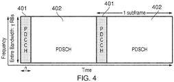
- FIG 4 provides a simplified diagram of a downlink subframe where a control channel and the PDSCH are shown.
- each subframe has a single PDDCH 401 in the control channel which spans a predetermined time period represented by n OFDM symbols and a PDSCH 402 which spans substantially the entire system bandwidth represented by y resource blocks.
- the form of subframe in Figure 4 is primarily designed for systems where there is a central eNodeB and both user data and control data are transmitted and received in the uplink and downlink by the eNodeB. However, restricting a system to operate in this manner may limit the flexibility and achievable data rates in the system.
- the UE may transmit data to a local low-power node which then communicates the data to the central eNodeB but still receive control data directly from the high-power serving eNodeB.
- the low-power node may also transmit downlink user data to the UE thus relieving the central eNodeB of this task.
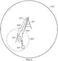
- Figure 5 provides a diagram of an example system where a first high-power eNodeB 501 provides a first coverage area 502 and a second low-power node 503 provides a second coverage area 504 which is smaller than and within the first coverage area 502.
- the node 502 may also be referred to as an umbrella or macro node and node 503 as a local or low-power node where the macro node provides coverage between the areas served by the local low-power nodes.
- the UE 505 is within both the first and second coverage areas and therefore is capable of communicating with both the central eNodeB 501 and the lower power node 503.
- a proportion of the control signalling is centrally transmitted from the eNodeB 501 to the UE, this signalling is common control signalling which multiple UEs in the cell 502 are required to receive and is represented by arrow 506.
- UE specific control signal is transmitted locally from the low power node 503 to the UE 505 and is represented by the dashed arrow 507 where the connection between the low-power node 503 and the eNodeB 501 may be provided by a backhaul connection.
- the macro node and the low-power node may transmit different control data, synchronisation signals broadcast signals and reference signals may stay the same between the macro node and the low-power node, for example PSS, SSS and PBCH signals may be common between the nodes.
- the UE specific user data is also transmitted locally from the low-power node and is represented by arrow 508 where once again the connection between the low-power node 503 and the eNodeB 501 may be provided by a backhaul connection.
- This decoupled arrangement can be lead to increases in capacity as the eNodeB is not required to transmit all UE user data within the coverage area 502. Instead a proportion of the UE user data is transmitted by low power local nodes such as 503. However this increase in capacity can come at the cost of increased control signalling and coordination between nodes and therefore may lead to control signalling overload at the eNodeB.
- the structure of Figure 5 may correspond to a heterogeneous network where the low-power node 503 may be referred to as a pico node or femto node.
- Pico or femto nodes may be placed in areas where there is particularly high demand in order to increase capacity to beyond the capacity that can be achieved with a single high-power node.
- a flexible control channel which allows the control channel in LTE systems to be tailored to the structure of the cell or coverage area in which it is being used. This flexibility thus allows the control channel to be adapted such that the likelihood of control overload can be reduced and transmission of control data more evenly and efficiently distributed between serving eNodeBs and local lower power nodes.
- the existing control channel and the one or more PDCCHs contained therein can only be dimensioned in time i.e. can vary in duration from one to four OFDM symbols depending on the number of subcarriers being utilised in the system.
- control channel modules which form the control channel are provided and can be dimensioned in the frequency domain such that the control channel is not restricted to a single continuous region spanning substantially the entire bandwidth of the system as illustrated in Figure 3 and 4 .
- the control channel modules may span mutually exclusive bandwidths and may allow one or more PDDCHs to be fully contained within a single control channel module such that PDDCHs may be received without receiving signals across the entire bandwidth of the control region.
- each control channel module is formed from part of the control region (i.e. predetermined system bandwidth) bandwidth, where the part of the system bandwidth which forms each control channel modules is smaller than the system bandwidth.
- FIG. 6 provides a schematic diagram of a control channel structure in accordance with an example embodiment of the present disclosure, where each control channel module contains a single PDDCH. However, each control channel module may also contain more than one PDDCH. Instead of a single continuous control channel in which PDCCHs are located, the control channel is formed from one or more independent control channel modules, where in the subframes of Figure 6 the control channel is formed from two control channel modules 601 and 602, each of which have a non-overlapping bandwidth less then the bandwidth of the system. These control channel modules may then be allocated to different nodes, for example an eNodeB and a low-power node as described with reference to Figure 5 .
- PDCCH data in each of the modules may then indicate the resources in the PDSCH 603 which have been allocated to the UE served by the nodes. Consequently, the PDCCH data may be received without receiving signals from across substantially the entire control region, in contrast to the case in existing LTE systems. Implementation of this flexible allocation may therefore require a revised mapping of resource elements to PDCCHs in the control modules compared to existing LTE control structures.
- the modular structure of the control channel allows the transmission of control data to be split between one or more nodes which may operate over same frequency so that the likelihood of control signalling overload at a node is reduced. This may be advantageous in heterogeneous networks where a single high power node is unable to provide sufficient capacity and a further node i.e.
- control channel 503 has been introduced in order to increase capacity.
- the structure of the control channel may be dynamically controlled by the eNodeB so that it can be adapted to suit the current or expected traffic conditions of the network. For example, if a large number of devices within area 504 become active the size control channel module 602 which is allocated to low-power node 503 may be increased and the size of control channel module 601 decreased, thus providing more capacity for control data from the low-power node 503.
- the different control channel modules may be allocated to different classes of devices, for instance module 601 may be allocated to high-bandwidth devices and 602 may be allocated to low-bandwidth devices.
- the division of the conventional control channel bandwidth into a number of independent control channel modules may in some examples result in legacy devices being unable to operate with the newly prosed modular formation because of the non-contiguous nature of the proposed control channel and the fact that PDDCHs may no longer be interleaved over substantially the entire bandwidth of the system.
- control channel modules may be of a single duration in time or their duration may vary with respect to each other.
- the duration and/or bandwidth of the control channel modules may be signalled in a module-specific PCFICH, signalled in a common PCFICH or be included in a commonly received default control channel module which is described in more detail below.
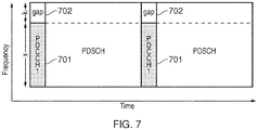
- FIG. 7 provides a schematic diagram of a control channel structure in accordance with another example embodiment of the present disclosure.
- the control channel is formed from a single control channel module 701 which has a bandwidth of x resource blocks where x is less than the bandwidth y of the system and the single control channel module may act as a reduced bandwidth PDDCH.
- x ⁇ y there is a bandwidth gap 702 of width k resource blocks between the control channel formed from the channel module 701 and the predetermined bandwidth of the system.
- This bandwidth gap may have a number of applications, for instance in may be used to provide auxiliary services, be used to serve narrowband devices or used as a frequency notch in order to reduce interface to other co-existing systems or avoid interference caused by co-existing systems.
- network traffic in a system is low the total bandwidth of the control channel can be reduced and therefore for the bandwidth gap increases so that UE is required to receive a smaller bandwidth, thus reducing power consumption.
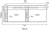
- FIG 8 provides a schematic diagram of a control channel structure where the bandwidth gap described with reference to Figure 7 has been utilised to provide a narrowband virtual carrier 801.
- a virtual carrier is an existing technique directed towards serving low-cost and low-complexity devices such as machine-type communications (MTC) devices as described in a number of copending patent applications GB 1101970.0 , GB 1101981.7 , GB 1101966.8 , GB 1101983.3 , GB 1101853.8 , GB 1101982.5 , GB 1101980.9 and GB 1101972.6 , the contents of which are incorporated herein by reference.
- MTC machine-type communications
- the use of a narrowband virtual carrier reduces the required operational bandwidth of a device's receiver thus in turn reducing the cost of such devices.
- virtual carriers with MTC devices allows these devices to operate alongside convention LTE devices, such as smartphones and tablets, with out requiring the same capabilities as conventional LTE devices.
- appropriate PDSCH scheduling will be required in order to ensure that conventional non-virtual carrier devices are not allocated PDSCH resources which fall within the virtual carrier bandwidth.
- the virtual carrier is positioned at the upper end of the predetermined system bandwidth it may be located at any point in the system bandwidth and in some examples more than one narrowband virtual carrier may be provided when one or more bandwidth gaps are provided.
- Figure 9 provides a schematic diagram of an example embodiment of a modular control channel structure when a plurality of nodes are each allocated a control channel module.
- the structure of the control channel in Figure 9 has been adapted for use in scenarios such as that illustrated in Figure 5 but the structure may be adapted for use where there is a plurality of low-power nodes serving under a single macro node.
- the control channel is formed from three control channel modules 901, 902 and 903.
- the control channel module 901 is allocated to the low-power node 503 for transmission of control data specific to devices serving the low-power node 503 and the control channel module 902 is allocated to the macro or high-power eNodeB 501 for transmission of control data specific to devices served by the macro node 501.
- the default control channel module 903 is allocated for transmission of control channel data required by all devices and may provide control information common to the macro cell and the small cell. Initially when a UE attempts to connect to the cell it will decode the default control information transmitted in control channel module 903, the default control information indicating for example the location and size of the other control channel modules and their relationship with the nodes 501 and 503. The UE will then subsequently decode the control information in the appropriate control channel module, for example module 901 if in area 501 or 903 if in area 504.
- the default control channel module 903 is likely to be transmitted by high-power node 501 such that it can be received by UEs throughout the cell area 502 but in some examples it may be transmitted by the low-power node 503.
- Common search space downlink control information may be provided in the macro control channel module 903 and UE-specific search space downlink control information provided in the macro control channel 903 or the low-power nodes control channel module 902 depending on the node serving a UE with downlink user data.
- Figure 10 provides a schematic diagram of an example embodiment where the control channel is formed from a plurality of control channel modules. This arrangement allows control channel modules to be allocated to numerous nodes and or UEs.
- the control channel is formed from control channel modules 1001, 1002, and 1003 and up to control channel module m 1004.
- Each control channel module may be allocated to different entities, for instance UEs based on their radio network temporary identifier (RNTI), and the allocation criteria broadcast in a default control channel module or provided in system specifications.
- RNTI radio network temporary identifier
- Restrictions may be placed on the serving eNodeB such that control channel modules allocated for a given RNTI may only span across resource blocks with the control channel bandwidth which satisfy a function of the RNTI.
- control channel modules for a particular RNTI may start and span resource blocks satisfying a modulo division of the RNTI.
- the maximum number of control channel modules is limited by their minimum size e.g. in Release-11 LTE specifications six resource blocks, and the maximum allowable bandwidth of the control channel.
- the maximum number of control channel modules may be equal to the number of Resource Blocks in Maximum Bandwidth/6 where the minimum size of a control channel module is six resource blocks.
- the control channel modules may be of varying sizes such that the eNodeB can allocate larger control channel modules to UEs or nodes requiring comparatively more control channel data.
- the control channel modules may be allocated on an individual UE or node basis, a module containing common search space downlink control information may be provided which includes common control data such as paging and random access responses. The location of such a control channel module may be stated in system specifications or signalled in broadcast data such as system information blocks.
- Figure 11 provides a schematic diagram of an example embodiment where the control channel is formed from a plurality of control channel modules and a bandwidth gap in the control channel has been left in between the control channel modules for the insertion of a narrowband virtual carrier.
- the control channel is formed from four control channel modules 1101 to 1104 where a bandwidth gap is provided between control channel modules 1103 and 1104.
- a narrowband virtual carrier then may be inserted in the bandwidth gap.
- the adaptable nature of having a plurality of independent control channel modules enables one or more virtual carriers to be inserted into any portion of the system bandwidth as opposed to a set position which cannot be varied by the eNodeB.
- the adaptable placement and size of the control channel modules also allows the virtual carrier to variable in size without requiring excess unused bandwidth in the control channel. For instance, a virtual carrier bandwidth may be varied between 24 and 18 resources blocks in some examples such that when the virtual carrier bandwidth is reduced to 18 blocks from 24 blocks, the control channel modules can be adapted and rearranged to utilise these extra resource blocks.
- a default control channel module may be provided in which the eNodeB transmits system information.
- These default control channel modules provide UEs with data required to initially camp-on to the cell without having to do perform blind decoding on all possible module sizes and the data contained in each module.
- the default control channel module may also provide information on the structure of the control channel modules including their beginning and end and the location of any blank control channel modules such that superfluous decoding and blind detection can be reduced.
- the location of the default control channel module may be hardcoded or signalled in broadcast system information and first acquired when camping-on to the wireless access interface. Additional control channel structure information may be signalled using the master information block where the system frame number, system bandwidth and control channel size can be indicated. Alternatively, using the PCFICH the number of control channel symbols and control channel size can be indicated.
- Figure 12 provides a flow diagram illustrating an example camp-on procedure of a UE and the initial stages in reception of control information when the control channel is formed from one or more control channel modules and a default control channel module is utilised to provide control channel structure information to UEs.
- This procedure includes the following steps at the UE
- the above procedure may include additional steps required to camp-on to an eNodeB and or some steps may be performed in a different order. For instance, it is possible that the size of the default control channel module may be detected at step S1208 instead of S1207.
- Figure 13 provides a schematic diagram of a UE 1301 and an eNodeB 1305 in which example embodiments of the present techniques may be implemented.
- the UE includes a transmitter 1302, a receiver 1303 and a controller 1304 where the controller is configured to control the receiver 1303 to detect signals representing the control data and user data transmitted by the eNodeB 1305, and to estimate the data conveyed by the signals.
- the controller 1304 is also configured to control the transmitter 1302 to transmit signals representing uplink data to the eNodeB.
- the UE 1301 may also detect signals transmitted by a low-power node or other network element.
- the eNodeB 1305 includes a transmitter 1306, a receiver 1307 and a controller 1308, where the controller 1308 is configured to control the transmitter 1306 to transmit signals representing control data and user data to the UE 1301.
- the controller 1308 is also configured to control the receiver 1307 to detect signals representing user uplink data and estimate the data conveyed by these signals.
- the controller at the eNodeB may dynamically control the structure of the modular control channel via broadcast messages or messages contained in default control channel modules, such that the structure of the control channel can be adapted to suit the current or expected traffic conditions in the network.
- the eNodeB when operating as a macro cell as illustrated in Figure 5 , may communicate control data via the wireless access interface to all nodes within its coverage area but also communicate control data to the low-power node via a backhaul link for transmission.
- the low-power node may perform some or all of the scheduling tasks and transmit this control data directly to the UEs within its coverage area.
Landscapes
- Engineering & Computer Science (AREA)
- Signal Processing (AREA)
- Computer Networks & Wireless Communication (AREA)
- Mobile Radio Communication Systems (AREA)
Description
- The present disclosure relates to network elements for forming part of mobile communications networks, communications systems, communications devices and methods of communicating data via a wireless access interface provided by a mobile communications network.
- Third as well as fourth generation mobile telecommunication systems, such as those based on the 3GPP defined UMTS and Long Term Evolution (LTE) architecture are able to support more sophisticated services than simple voice and messaging services offered by previous generations of mobile telecommunication systems.
- For example, with the improved radio interface and enhanced data rates provided by LTE systems, a user is able to enjoy on high data rate applications such as video streaming and video conferencing on mobile communications devices that would previously only have been available via a fixed line data connection. The demand to deploy fourth generation networks is therefore strong and the coverage area of these networks, i.e. geographic locations where access to the networks is possible, is expected to increase rapidly.
- The anticipated widespread deployment of fourth generation networks has led to the parallel development of a class of communications devices and applications which, rather than taking advantage of the high data rates available, instead take advantage of the robust radio interface and increasing ubiquity of the coverage area. Examples include so-called machine type communication (MTC) applications, which are typified by semi-autonomous or autonomous wireless communication devices communicating small amounts of data on a relatively infrequent basis. Examples include so-called smart meters which, for example, are located in a customer's house and periodically transmit information relating to the customers consumption of a utility such as gas, water, electricity and so on.
- The variety of devices anticipated to operate in LTE systems have a range of different usage requirements and therefore it would be beneficial if LTE systems are able to provide a wireless access interface which can be tailored to the requirements of the different classes of devices. For example, high bandwidth devices such as smartphones and tablets may benefit from a wireless access interface with a high capacity whereas MTC devices may benefit from a reduced complexity lower capacity wireless access interface with a capability to transmit small amounts of data more efficiently, since lower complexity typically implies lower device cost. A number of approaches currently exist to address these problems, for example, by providing a heterogeneous communication network where a number of low-power nodes provide additional coverage within a coverage area of a high-power umbrella or macro node, system capacity may be increased. Alternatively, for MTC devices a virtual carrier approach has been proposed where a reduced bandwidth segment of the wireless access interface is reserved for use by MTC devices thus allowing these devices to transmit and receive data over a reduced bandwidth and in turn lowering their complexity and cost.
- However, although these approaches each provide a wireless access interface tailored to different classes of device, the complexity of the resource allocation associated is potentially complex and may lead to increased control signalling overheads. Prior art document
US 2013/077597A1 discloses methods and apparatuses for control channel communication between mobile wireless devices and a wireless network wherein a first control channel and a second control channel can be separate logical channels on the same physical control channel PDCCH. - The invention is set out in the appended set of claims. The embodiments and/or examples of the following description which are not covered by the appended claims are considered as not being part of the present invention.
- According to an example embodiment of the present disclosure there is provided a network element for forming a mobile communications network, the network element configured to provide a wireless access interface to one or more communications devices and to transmit downlink data to and receive uplink data from the one or more communications devices via the wireless access interface. The downlink resources of the wireless access interface extending across a predetermined bandwidth and being divided in time into a plurality of timeframes. The network element comprising a transmitter and a controller, the controller being configured to control the transmitter to transmit control data to the communications devices in resources of a control channel, wherein the control channel is formed a plurality of control channel modules, each control channel module being formed from a part of the predetermined bandwidth, each of the parts of the predetermined bandwidth from which each of the control channels is formed being smaller than the predetermined bandwidth and mutually exclusive from the parts of the predetermined bandwidth from which the other control channel modules are formed .
- Providing a control channel formed from a plurality of control channel modules allows different portions of the control channel to be allocated to different network elements in a heterogeneous network or different communications devices. This allocation may then reduce the need for communications devices to receive the entirety or a significant portion of data within the control channel, thus increasing the efficiency and flexibility of resource allocation. The potentially reduced size of the control channel compared to the predetermined bandwidth of the wireless access interface also provides spare bandwidth, which instead of being occupied by the control channel can be used for the provision of additional services. Furthermore, physical downlink control channel (PDDCH) information may be contained within a single control channel module such that PDDCH information can be detected and decoded without receiving signals from across the entirety of the predetermined bandwidth.
- In one example embodiment each of the control channel modules has a substantially equal time duration within the frame. Providing the control channel modules with a single duration allows a single indication of module duration to be provided instead of a separate indication for each control channel module, thus conserving capacity in the system
- In one example each of the control channel modules having unequal time durations within the frame.
- Providing the control channel modules with unequal durations allows the resources dedicated to the control channel to be more flexibility allocated, thus potential improving the efficiency of the system.
- In one example the network element is configured to provide the wireless access interface to communication devices within a first geographical area, and the controller is configured to control the transmitter to transmit control data to the communications devices within the first geographical area in one of the plurality of control channel modules.
- Providing a plurality of control channel modules allows different nodes in a decoupled network to be allocated different control channel modules such that communications devices receive control data in a control channel module which corresponds to the coverage area in which they are currently located. This may therefore reduce the volume of control data that communications devices are required to receive.
- In one example embodiment the bandwidth of the control channel is less than the predetermined bandwidth, such that a difference in the bandwidth between the control channel and the predetermined bandwidth provides a bandwidth gap, wherein the controller is configured to control the transmitter to provide a narrowband virtual carrier in the bandwidth gap.
- The provision of a bandwidth gap allows additional services to be provided to communications devices anywhere in the predetermined system bandwidth where control data would conventionally be situated. The bandwidth gap may also be utilised to reduce and or avoid interference thus also increasing the robustness of the wireless access interface.
- The provision of a narrowband virtual carrier in the bandwidth gaps allows narrowband devices such as MTC devices to operate within the predetermined system bandwidth without disrupting the allocation of control channel resources to conventional communications devices.
- In one example embodiment the controller is configured to allocate each of the control channel modules to communications devices in dependence upon an identity of each of the communications devices.
- The allocation of control channel modules based on the identity of the communication devices identity enables a communications device to calculate the allocation of control channel resources without having to receive an explicit indication control channel resource allocation.
- In one example embodiment the controller is configured to control the transmitter to provide in a predetermined control module an indication of the bandwidth and location of the plurality control channel modules.
- The provision of a predetermined control channel module enables communications devices to obtain an indication of the structure of the control channel without having to receive control channel data across the entirety or a substantial portion of the control channel bandwidth.
- Various further aspects and embodiments of the disclosure are provided in the appended claims, including but not limited to a communications system, a communications device and a method of communicating.
- Embodiments of the present disclosure will now be described by way of example only with reference to the accompanying drawing in which like parts are provided with corresponding reference numerals and in which:
-
Figure 1 provides a schematic diagram of a communications network; -
Figure 2 provides a schematic diagram of an example conventional LTE radio frame; -
Figure 3 provides a schematic diagram of an example conventional LTE subframe; -
Figure 4 provides a schematic diagram of two example conventional LTE subframes; -
Figure 5 provides a schematic diagram of an example heterogeneous communications network; -
Figure 6 provides a schematic diagram of two LTE subframes in accordance with an example of the present disclosure; -
Figure 7 provides a schematic diagram of two LTE subframes in accordance with an example of the present disclosure; -
Figure 8 provides a schematic diagram of two LTE subframes in accordance with an example of the present disclosure; -
Figure 9 provides a schematic diagram of two LTE subframes in accordance with an example of the present disclosure; -
Figure 10 provides a schematic diagram of two LTE subframe in accordance with an example of the present disclosure; -
Figure 11 provides a schematic diagram of two LTE subframe in accordance with an example of the present disclosure; -
Figure 12 provides a flow diagram of an LTE camp-on procedure in accordance with an example of the present disclosure; and -
Figure 13 provides a schematic diagram of a communications device and a network element in accordance with an example of the present disclosure. -
Figure 1 provides a schematic diagram illustrating the basic functionality of a conventional mobile telecommunications network. The network includes a plurality ofbase stations 101 connected to acore network 102. Each base station provides a wireless access interface to a respective coverage area 103 (i.e. a cell) within which data can be communicated to and frommobile terminals 104 via the wireless access interface provided by the respective base station. Data is transmitted from abase station 101 to amobile terminal 104 within acoverage area 103 via a radio downlink. Data is transmitted from amobile terminal 104 to abase station 101 via a radio uplink. Thecore network 102 routes data to and from themobile terminals 104 and provides functions such as authentication, mobility management, charging and so on. A mobile terminal may also be referred to as user equipment (UE) or a communications device and a base station as an enhanced node B (eNodeB) or network element. - Mobile telecommunications systems such as those arranged in accordance with the 3GPP defined Long Term Evolution (LTE) architecture use an orthogonal frequency division multiplex (OFDM) based interface for the radio downlink (so-called OFDMA) and a single-carrier frequency division multiple access based interface for the radio uplink (so-called SC-FDMA). Data is transmitted on the uplink and on the downlink on a plurality of orthogonal subcarriers.
Figure 2 shows a schematic diagram illustrating an OFDM based LTEdownlink radio frame 201. The LTE downlink radio frame is transmitted from an LTE base station (known as an enhanced Node B) and lasts 10 ms. The downlink radio frame comprises ten subframes, each subframe lasting 1 ms. A primary synchronisation signal (PSS) and a secondary synchronisation signal (SSS) are transmitted in the first and sixth subframes of the LTE frame. A physical broadcast channel (PBCH) is located in the first subframe of the LTE frame. The PSS, SSS and PBCH are discussed in more detail below. -
Figure 3 provides a schematic diagram providing a grid which illustrates the structure of an example of a conventional downlink LTE subframe. The subframe comprises a predetermined number of symbols which are transmitted over a 1ms period. Each symbol comprises a predetermined number of orthogonal subcarriers distributed across the bandwidth of the downlink radio carrier. The example subframe shown inFigure 3 comprises 14 symbols and 1200 subcarriers spaced across a 20MHz bandwidth. The smallest unit on which data can be transmitted in LTE is twelve subcarriers transmitted over one subframe. For clarity, inFigure 3 , each individual resource element is not shown, instead each individual box in the subframe grid corresponds to twelve subcarriers transmitted on one symbol.Figure 3 shows resource allocations for fourUEs resource allocation 342 forUE 1 extends over five blocks of twelve subcarriers, theresource allocation 343 for asecond UE 2 extends over six blocks of twelve subcarriers and so on. - Signals representing control data are transmitted in a
control region 300 of the subframe comprising the first n symbols of the subframe where n can vary between one and three symbols for channel bandwidths of more than 1.4 MHz and where n can vary between two and four symbols for channel bandwidths of up to and including 1.4MHz. Thecontrol region 300 includes a control channel which spans the control region and in which data is transmitted on one or more physical downlink control channels (PDCCH), the physical control format indicator channel (PCFICH) and the physical HARQ indicator channel (PHICH). - A PDCCH may contain control data common to all UEs or control data specific to one or more UEs. The control data may comprise information to control relevant UEs but also information to indicate which subcarriers on which symbols of the subframe have been allocated to data for UEs. Each PDDCH conveys one instance of a downlink control information (DCI) and is interleaved across the control channel, therefore a receiver is required to receive signals from across the entire control region in order to decode data conveyed by a PDCCHs For example, PDCCH data transmitted in the
control region 300 of the subframe shown inFigure 3 would indicate that UE1 has been allocated the first block ofresources 342, that UE2 has been allocated the second block ofresources 343, and so on. In subframes where it is transmitted, the PCFICH contains control data indicating the duration of the control region in that subframe (i.e. between one and four symbols) and the PHICH contains HARQ (Hybrid Automatic Request) data indicating whether or not previously transmitted uplink data has been successfully received by the network. - In certain subframes, symbols in a
central band 310 of the subcarriers are used for the transmission of information including the PSS, the SSS and the PBCH mentioned above. Thiscentral band 310 is typically 72 subcarriers wide (corresponding to a transmission bandwidth of 1.08 MHz). The PSS and SSS are synchronisation sequences that once detected allow a communications terminal 104 to achieve frame synchronisation and determine the cell identity of the eNodeB transmitting the downlink signal. The PBCH carries information about the cell, comprising a master information block (MIB) that includes parameters that the communications terminals require to access the cell. The data transmitted to individual communications terminals on the physical downlink shared channel (PDSCH) can be transmitted in the remaining blocks of communications resource elements of the subframe. -
Figure 3 also shows a region of PDSCH containing system information and extending over a bandwidth of R344. Thus inFigure 3 the central frequency carries control channels such as the PSS, SSS and PBCH and therefore implies a minimum bandwidth of a receiver of a communications terminal. - The number of subcarriers in an LTE channel can vary depending on the configuration of the transmission network. Typically this variation is from 72 sub carriers contained within a 1.4MHz channel bandwidth to 1200 subcarriers contained within a 20MHz channel bandwidth as shown in
Figure 3 . As is known in the art, subcarriers carrying data transmitted on the PDCCHs, PCFICH and PHICH are typically distributed across the entire bandwidth of the subframe. Therefore a conventional communications terminal must be able to receive the entire bandwidth of the subframe in order to receive and decode the control region. -
Figure 4 provides a simplified diagram of a downlink subframe where a control channel and the PDSCH are shown. InFigure 4 , each subframe has asingle PDDCH 401 in the control channel which spans a predetermined time period represented by n OFDM symbols and aPDSCH 402 which spans substantially the entire system bandwidth represented by y resource blocks. The form of subframe inFigure 4 is primarily designed for systems where there is a central eNodeB and both user data and control data are transmitted and received in the uplink and downlink by the eNodeB. However, restricting a system to operate in this manner may limit the flexibility and achievable data rates in the system. For example, due to the limited transmission power at a UE, it may be beneficial for the UE to transmit data to a local low-power node which then communicates the data to the central eNodeB but still receive control data directly from the high-power serving eNodeB. Furthermore, the low-power node may also transmit downlink user data to the UE thus relieving the central eNodeB of this task. -
Figure 5 provides a diagram of an example system where a first high-power eNodeB 501 provides afirst coverage area 502 and a second low-power node 503 provides asecond coverage area 504 which is smaller than and within thefirst coverage area 502. Thenode 502 may also be referred to as an umbrella or macro node andnode 503 as a local or low-power node where the macro node provides coverage between the areas served by the local low-power nodes. TheUE 505 is within both the first and second coverage areas and therefore is capable of communicating with both thecentral eNodeB 501 and thelower power node 503. A proportion of the control signalling is centrally transmitted from theeNodeB 501 to the UE, this signalling is common control signalling which multiple UEs in thecell 502 are required to receive and is represented byarrow 506. UE specific control signal is transmitted locally from thelow power node 503 to theUE 505 and is represented by the dashedarrow 507 where the connection between the low-power node 503 and theeNodeB 501 may be provided by a backhaul connection. Although the macro node and the low-power node may transmit different control data, synchronisation signals broadcast signals and reference signals may stay the same between the macro node and the low-power node, for example PSS, SSS and PBCH signals may be common between the nodes. The UE specific user data is also transmitted locally from the low-power node and is represented byarrow 508 where once again the connection between the low-power node 503 and theeNodeB 501 may be provided by a backhaul connection. This decoupled arrangement can be lead to increases in capacity as the eNodeB is not required to transmit all UE user data within thecoverage area 502. Instead a proportion of the UE user data is transmitted by low power local nodes such as 503. However this increase in capacity can come at the cost of increased control signalling and coordination between nodes and therefore may lead to control signalling overload at the eNodeB. In some examples the structure ofFigure 5 may correspond to a heterogeneous network where the low-power node 503 may be referred to as a pico node or femto node. Pico or femto nodes may be placed in areas where there is particularly high demand in order to increase capacity to beyond the capacity that can be achieved with a single high-power node. - In accordance with the present disclosure a flexible control channel is provided which allows the control channel in LTE systems to be tailored to the structure of the cell or coverage area in which it is being used. This flexibility thus allows the control channel to be adapted such that the likelihood of control overload can be reduced and transmission of control data more evenly and efficiently distributed between serving eNodeBs and local lower power nodes. As described with reference to
Figure 3 and4 , the existing control channel and the one or more PDCCHs contained therein can only be dimensioned in time i.e. can vary in duration from one to four OFDM symbols depending on the number of subcarriers being utilised in the system. In accordance with the present disclosure one or more control channel modules which form the control channel are provided and can be dimensioned in the frequency domain such that the control channel is not restricted to a single continuous region spanning substantially the entire bandwidth of the system as illustrated inFigure 3 and4 . The control channel modules may span mutually exclusive bandwidths and may allow one or more PDDCHs to be fully contained within a single control channel module such that PDDCHs may be received without receiving signals across the entire bandwidth of the control region. Furthermore, each control channel module is formed from part of the control region (i.e. predetermined system bandwidth) bandwidth, where the part of the system bandwidth which forms each control channel modules is smaller than the system bandwidth. -
Figure 6 provides a schematic diagram of a control channel structure in accordance with an example embodiment of the present disclosure, where each control channel module contains a single PDDCH. However, each control channel module may also contain more than one PDDCH. Instead of a single continuous control channel in which PDCCHs are located, the control channel is formed from one or more independent control channel modules, where in the subframes ofFigure 6 the control channel is formed from twocontrol channel modules Figure 5 . PDCCH data in each of the modules may then indicate the resources in thePDSCH 603 which have been allocated to the UE served by the nodes. Consequently, the PDCCH data may be received without receiving signals from across substantially the entire control region, in contrast to the case in existing LTE systems. Implementation of this flexible allocation may therefore require a revised mapping of resource elements to PDCCHs in the control modules compared to existing LTE control structures. The modular structure of the control channel allows the transmission of control data to be split between one or more nodes which may operate over same frequency so that the likelihood of control signalling overload at a node is reduced. This may be advantageous in heterogeneous networks where a single high power node is unable to provide sufficient capacity and a further node i.e. 503 has been introduced in order to increase capacity. The structure of the control channel may be dynamically controlled by the eNodeB so that it can be adapted to suit the current or expected traffic conditions of the network. For example, if a large number of devices withinarea 504 become active the sizecontrol channel module 602 which is allocated to low-power node 503 may be increased and the size ofcontrol channel module 601 decreased, thus providing more capacity for control data from the low-power node 503. In some examples, the different control channel modules may be allocated to different classes of devices, forinstance module 601 may be allocated to high-bandwidth devices and 602 may be allocated to low-bandwidth devices. - In
Figure 6 thecontrol channel modules channel module 601 spans a bandwidth of x resource blocks (12x subcarriers) andcontrol channel module 602 spans k resource blocks (12k subcarriers), where y=x+k. The division of the conventional control channel bandwidth into a number of independent control channel modules may in some examples result in legacy devices being unable to operate with the newly prosed modular formation because of the non-contiguous nature of the proposed control channel and the fact that PDDCHs may no longer be interleaved over substantially the entire bandwidth of the system. However, this may be overcome by the eNodeB switching between the existing control channel structure and the proposed control channel structure, and signalling any such switching to UEs being served.. The control channel modules may be of a single duration in time or their duration may vary with respect to each other. The duration and/or bandwidth of the control channel modules may be signalled in a module-specific PCFICH, signalled in a common PCFICH or be included in a commonly received default control channel module which is described in more detail below. -
Figure 7 provides a schematic diagram of a control channel structure in accordance with another example embodiment of the present disclosure. The control channel is formed from a singlecontrol channel module 701 which has a bandwidth of x resource blocks where x is less than the bandwidth y of the system and the single control channel module may act as a reduced bandwidth PDDCH. As a result of x<y there is abandwidth gap 702 of width k resource blocks between the control channel formed from thechannel module 701 and the predetermined bandwidth of the system. This bandwidth gap may have a number of applications, for instance in may be used to provide auxiliary services, be used to serve narrowband devices or used as a frequency notch in order to reduce interface to other co-existing systems or avoid interference caused by co-existing systems. Alternatively, if network traffic in a system is low the total bandwidth of the control channel can be reduced and therefore for the bandwidth gap increases so that UE is required to receive a smaller bandwidth, thus reducing power consumption. -
Figure 8 provides a schematic diagram of a control channel structure where the bandwidth gap described with reference toFigure 7 has been utilised to provide a narrowbandvirtual carrier 801. A virtual carrier is an existing technique directed towards serving low-cost and low-complexity devices such as machine-type communications (MTC) devices as described in a number of copending patent applicationsGB 1101970.0 GB 1101981.7 GB 1101966.8 GB 1101983.3 GB 1101853.8 GB 1101982.5 GB 1101980.9 GB 1101972.6 Figure 8 , appropriate PDSCH scheduling will be required in order to ensure that conventional non-virtual carrier devices are not allocated PDSCH resources which fall within the virtual carrier bandwidth. Although inFigure 8 the virtual carrier is positioned at the upper end of the predetermined system bandwidth it may be located at any point in the system bandwidth and in some examples more than one narrowband virtual carrier may be provided when one or more bandwidth gaps are provided. -
Figure 9 provides a schematic diagram of an example embodiment of a modular control channel structure when a plurality of nodes are each allocated a control channel module. The structure of the control channel inFigure 9 has been adapted for use in scenarios such as that illustrated inFigure 5 but the structure may be adapted for use where there is a plurality of low-power nodes serving under a single macro node. The control channel is formed from threecontrol channel modules control channel module 901 is allocated to the low-power node 503 for transmission of control data specific to devices serving the low-power node 503 and thecontrol channel module 902 is allocated to the macro or high-power eNodeB 501 for transmission of control data specific to devices served by themacro node 501. The defaultcontrol channel module 903 is allocated for transmission of control channel data required by all devices and may provide control information common to the macro cell and the small cell. Initially when a UE attempts to connect to the cell it will decode the default control information transmitted incontrol channel module 903, the default control information indicating for example the location and size of the other control channel modules and their relationship with thenodes example module 901 if inarea area 504. The defaultcontrol channel module 903 is likely to be transmitted by high-power node 501 such that it can be received by UEs throughout thecell area 502 but in some examples it may be transmitted by the low-power node 503. The modular arrangement illustrated inFigure 9 advantageously reduces the volume of scheduling data thenode 501 is required to transmit and therefore reduces the likelihood that thenode 501 encounters a control data overload. Common search space downlink control information may be provided in the macrocontrol channel module 903 and UE-specific search space downlink control information provided in themacro control channel 903 or the low-power nodes controlchannel module 902 depending on the node serving a UE with downlink user data. -
Figure 10 provides a schematic diagram of an example embodiment where the control channel is formed from a plurality of control channel modules. This arrangement allows control channel modules to be allocated to numerous nodes and or UEs. InFigure 10 the control channel is formed fromcontrol channel modules channel module m 1004. Each control channel module may be allocated to different entities, for instance UEs based on their radio network temporary identifier (RNTI), and the allocation criteria broadcast in a default control channel module or provided in system specifications. Restrictions may be placed on the serving eNodeB such that control channel modules allocated for a given RNTI may only span across resource blocks with the control channel bandwidth which satisfy a function of the RNTI. For instance, control channel modules for a particular RNTI may start and span resource blocks satisfying a modulo division of the RNTI. For example, a control channel module may start in resource blocks whereRNIT mod 3 = 0 and span a number of resource blocks whereRNTI mod 3 = 0. Although this approach increases the restrictions on control channel module allocation and may increase complexity at the eNodeB, it may simplify the process of searching for relevant control channel modules by the UEs, thus reducing their power consumption. - In
Figure 10 the maximum number of control channel modules is limited by their minimum size e.g. in Release-11 LTE specifications six resource blocks, and the maximum allowable bandwidth of the control channel. For instance the maximum number of control channel modules may be equal to the number of Resource Blocks in Maximum Bandwidth/6 where the minimum size of a control channel module is six resource blocks. As illustrated inFigure 10 the control channel modules may be of varying sizes such that the eNodeB can allocate larger control channel modules to UEs or nodes requiring comparatively more control channel data. Although the control channel modules may be allocated on an individual UE or node basis, a module containing common search space downlink control information may be provided which includes common control data such as paging and random access responses. The location of such a control channel module may be stated in system specifications or signalled in broadcast data such as system information blocks. -
Figure 11 provides a schematic diagram of an example embodiment where the control channel is formed from a plurality of control channel modules and a bandwidth gap in the control channel has been left in between the control channel modules for the insertion of a narrowband virtual carrier. InFigure 11 the control channel is formed from four control channel modules 1101 to 1104 where a bandwidth gap is provided between control channel modules 1103 and 1104. In an analogous manner to that described with reference toFigure 8 , a narrowband virtual carrier then may be inserted in the bandwidth gap. Once again appropriate scheduling for the PDSCH will be also be required in order for clear space in the PDSCH to be allocated to the virtual carrier. The adaptable nature of having a plurality of independent control channel modules enables one or more virtual carriers to be inserted into any portion of the system bandwidth as opposed to a set position which cannot be varied by the eNodeB. The adaptable placement and size of the control channel modules also allows the virtual carrier to variable in size without requiring excess unused bandwidth in the control channel. For instance, a virtual carrier bandwidth may be varied between 24 and 18 resources blocks in some examples such that when the virtual carrier bandwidth is reduced to 18 blocks from 24 blocks, the control channel modules can be adapted and rearranged to utilise these extra resource blocks. - In some implementations of the preceding example embodiments a default control channel module may be provided in which the eNodeB transmits system information. These default control channel modules provide UEs with data required to initially camp-on to the cell without having to do perform blind decoding on all possible module sizes and the data contained in each module. The default control channel module may also provide information on the structure of the control channel modules including their beginning and end and the location of any blank control channel modules such that superfluous decoding and blind detection can be reduced. The location of the default control channel module may be hardcoded or signalled in broadcast system information and first acquired when camping-on to the wireless access interface. Additional control channel structure information may be signalled using the master information block where the system frame number, system bandwidth and control channel size can be indicated. Alternatively, using the PCFICH the number of control channel symbols and control channel size can be indicated.
-
Figure 12 provides a flow diagram illustrating an example camp-on procedure of a UE and the initial stages in reception of control information when the control channel is formed from one or more control channel modules and a default control channel module is utilised to provide control channel structure information to UEs. This procedure includes the following steps at the UE - S1201: Acquiring the frequency of the serving eNodeB;
- S1202: Detecting the primary synchronisation signal (PSS) in order to obtain slot timing and SSS scrambling code;
- S1203: Detecting the secondary synchronisation signal (SSS) in order to obtain frame timing and cell group ID sequence;
- S1204: Calculating the cell ID using PSS and SSS;
- S1205: Detecting the reference signal location using cell ID;
- S1206: Detecting the master information block (MIB) in the PBCH;
- S1207: Detecting size of the default control channel model using the MIB, system frame number and system bandwidth;
- S1208: Decoding PCFICH and detecting symbols allocated to the control channel;
- S1209: Decoding downlink control information for system information block 1 from default control channel module;
- S1210: Decoding
system information block 1 and detecting size of corresponding control channel module which includes scheduling information for other SIBs; - S1211: Decoding other system information blocks;
- The above procedure may include additional steps required to camp-on to an eNodeB and or some steps may be performed in a different order. For instance, it is possible that the size of the default control channel module may be detected at step S1208 instead of S1207.
-
Figure 13 provides a schematic diagram of aUE 1301 and aneNodeB 1305 in which example embodiments of the present techniques may be implemented. The UE includes atransmitter 1302, areceiver 1303 and acontroller 1304 where the controller is configured to control thereceiver 1303 to detect signals representing the control data and user data transmitted by theeNodeB 1305, and to estimate the data conveyed by the signals. Thecontroller 1304 is also configured to control thetransmitter 1302 to transmit signals representing uplink data to the eNodeB. As well as detecting signals transmitted by theeNodeB 1305, theUE 1301 may also detect signals transmitted by a low-power node or other network element. TheeNodeB 1305 includes atransmitter 1306, areceiver 1307 and acontroller 1308, where thecontroller 1308 is configured to control thetransmitter 1306 to transmit signals representing control data and user data to theUE 1301. Thecontroller 1308 is also configured to control thereceiver 1307 to detect signals representing user uplink data and estimate the data conveyed by these signals. The controller at the eNodeB may dynamically control the structure of the modular control channel via broadcast messages or messages contained in default control channel modules, such that the structure of the control channel can be adapted to suit the current or expected traffic conditions in the network. The eNodeB when operating as a macro cell as illustrated inFigure 5 , may communicate control data via the wireless access interface to all nodes within its coverage area but also communicate control data to the low-power node via a backhaul link for transmission. Alternatively, the low-power node may perform some or all of the scheduling tasks and transmit this control data directly to the UEs within its coverage area. - Various further aspects and features of the present invention are defined in the appended claims and various combinations of the features of the dependent claims may be made with those of the independent claims other than the specific combinations recited for the claim dependency. For instance, although a feature may appear to be described in connection with particular embodiments, one skilled in the art would recognise that various features of the described embodiments may be combined in accordance with the disclosure.
Claims (15)
- A network element (1305) for forming a mobile communications network, the network element comprising
a transmitter (1306) configured to transmit signals via a wireless access interface to one or more communications devices (1301),
a receiver (1307) configured to receive signals from the one or more communications devices via the wireless access interface, and
a controller (1308) configured to control the transmitter and the receiver to form the wireless access interface, the wireless access interface including downlink resources extending across a predetermined bandwidth and being divided in time into a plurality of frames, and to control the transmitter
to transmit control data to the communications devices in resources of a control channel, wherein the control channel is formed from a plurality of control channel modules (601, 602), each control channel module being formed from a part of the predetermined bandwidth, the part of the predetermined bandwidth of each control channel module being less than the predetermined bandwidth and mutually exclusive from the parts of the predetermined bandwidths from which the other control channel modules are formed,
wherein the controller is configured to dynamically control the size of the part of the predetermined bandwidth of each control channel module based on current or expected traffic conditions of the network, and
wherein the controller is configured to control the transmitter to transmit an indication of the size of the part of the predetermined bandwidth of each control channel module to the communications devices in a default control channel module. - A network element as claimed in Claim 1, wherein the plurality of control channel modules each have a substantially equal time duration within the frame.
- A network element as claimed in Claim 1, wherein at least one of the plurality of control channel modules has a time duration unequal to at least one other of the plurality of the control channel modules within the frame.
- A network element as claimed in Claim 1, wherein the network element is configured to provide the wireless access interface to communication devices within a first geographical area, and the controller is configured to control the transmitter to transmit the control data to the communications devices within the first geographical area in a control channel module from the plurality of control channel modules.
- A network element as claimed in Claim 1, wherein a bandwidth occupied by the plurality of control channel modules is less than the predetermined bandwidth, such that a difference in the bandwidth occupied by the plurality of control channel modules and the predetermined bandwidth provides a bandwidth gap, wherein the controller is configured to control the transmitter to provide a narrowband virtual carrier in the bandwidth gap.
- A network element as claimed in Claim 1, wherein the controller is configured to allocate each of the control channel modules to communications devices in dependence upon an identity of each of the communications devices.
- A network element as claimed in Claim 1, wherein the controller is configured to control the transmitter to provide in a predetermined one of the plurality of control modules an indication of the bandwidth and the location of each of the plurality of the other control channel modules.
- A communications device (1301) for communicating with a network element (1305) of a communications network, the network element configured to provide a wireless access interface to the communications device, the communications device comprising
a transmitter (1302) configured to transmit uplink signals to the network element via the wireless access interface,
a receiver (1303) configured to receive downlink signals from the network element via the wireless access interface via downlink resources of the wireless access interface, the wireless access extending across a predetermined bandwidth and being divided in time into a plurality of frames, and
a controller (1304) configured to control the receiver
to detect control data transmitted by the network element in a control channel of the wireless access interface, wherein the control channel is formed from a plurality of control channel modules (601, 602), each control channel module being formed from a part of the predetermined bandwidth, the part of the predetermined bandwidth of each control channel module being less than the predetermined bandwidth and mutually exclusive from the parts of the predetermined bandwidths from which the other control channel modules are formed, wherein the size of the part of the predetermined bandwidth of each control channel module is dynamically controlled based on current or expected traffic conditions of the network, and
to receive, from the network element, an indication of the size of the part of the predetermined bandwidth of each control channel module in a default control channel module. - A communications device as claimed in Claim 8, wherein a predetermined control channel module provides an indication of the bandwidth and the location of each of the plurality of the other control channel modules and the controller is configured to control the receiver to detect the indication from the predetermined control channel and to detect the control data from another control channel module of the plurality of control channel modules based on the indication.
- A communications system comprising a mobile communications network and a communications device (1301) for communicating via the mobile communications network, the mobile communications network including
a network element (1305) configured to transmit signals using a transmitter (1306) via a wireless access interface to the communications device, to receive signals using a receiver (1307) from the communications device via the wireless access interface, and to control the transmitter and the receiver to form the wireless access interface, the wireless access interface including downlink resources extending across a predetermined bandwidth and being divided in time into a plurality of frames, and to control the transmitter
to transmit control data to the communications device in resources of a control channel, wherein the control channel is formed from f a plurality of control channel modules (601, 602), each control channel module being formed from a part of the predetermined bandwidth, the part of the predetermined bandwidth of each control channel module being less than the predetermined bandwidth and mutually exclusive from the parts of the predetermined bandwidths from which the other control channel modules are formed,
wherein the network element is configured to dynamically control the size of the part of the predetermined bandwidth of each control channel module based on current or expected traffic conditions of the network, and
wherein the network element is configured to transmit an indication of the size of the part of the predetermined bandwidth of each control channel module to the communications devices in a default control channel module. - A communications system as claimed in Claim 10, wherein the plurality of control channel modules each have a substantially equal time duration within the frame.
- A communications system as claimed in Claim 10, wherein at least one of the plurality of control channel modules has a time duration unequal to at least one other of the plurality of the control channel modules within the frame.
- A communications system as claimed in Claim 10, wherein the network element is configured to provide the wireless access interface to the communication device within a first area, and the controller is configured to control the transmitter to transmit the control data to the communications device within the first area in the control channel module from the plurality of control channel modules.
- A communications system as claimed in Claim 10, wherein a bandwidth occupied by the plurality of control channel modules is less than the predetermined bandwidth, such that a difference in the bandwidth occupied by the plurality of control channel modules and the predetermined bandwidth provides a bandwidth gap during the predetermined time period, wherein the controller is configured to control the transmitter to provide a narrowband virtual carrier within the bandwidth gap.
- A method of communicating via a mobile communications network, comprising
transmitting signals via a wireless access interface to one or more communications devices (1301),
receiving signals from the one or more communications devices via the wireless access interface, and
controlling the transmitting and the receiving to form the wireless access interface, the wireless access interface including downlink resources extending across a predetermined bandwidth and being divided in time into a plurality of timeframes, and the control the transmitting includes
transmitting control data to the communications devices in resources of a control channel, wherein the control channel is formed from a plurality of control channel modules (601, 602), each control channel module being formed from a part of the predetermined bandwidth, the part of the predetermined bandwidth of each control channel module being less than the predetermined bandwidth and mutually exclusive from the parts of the predetermined bandwidths from which the other control channel modules are formed, wherein the method further comprises
dynamically controlling the size of the part of the predetermined bandwidth of each control channel module based on current or expected traffic conditions of the network, and
transmitting an indication of the size of the part of the predetermined bandwidth of each control channel module to the communications devices in a default control channel module.
Priority Applications (1)
| Application Number | Priority Date | Filing Date | Title |
|---|---|---|---|
| EP14787165.1A EP3061202B1 (en) | 2013-10-31 | 2014-10-21 | Network element and method of communicating using a plurality of control channels modules |
Applications Claiming Priority (3)
| Application Number | Priority Date | Filing Date | Title |
|---|---|---|---|
| EP13191208 | 2013-10-31 | ||
| EP14787165.1A EP3061202B1 (en) | 2013-10-31 | 2014-10-21 | Network element and method of communicating using a plurality of control channels modules |
| PCT/EP2014/072574 WO2015062918A1 (en) | 2013-10-31 | 2014-10-21 | Network element and method of communicating using a plurality of controls channels modules |
Publications (2)
| Publication Number | Publication Date |
|---|---|
| EP3061202A1 EP3061202A1 (en) | 2016-08-31 |
| EP3061202B1 true EP3061202B1 (en) | 2018-12-12 |
Family
ID=49517340
Family Applications (1)
| Application Number | Title | Priority Date | Filing Date |
|---|---|---|---|
| EP14787165.1A Active EP3061202B1 (en) | 2013-10-31 | 2014-10-21 | Network element and method of communicating using a plurality of control channels modules |
Country Status (3)
| Country | Link |
|---|---|
| US (2) | US10321456B2 (en) |
| EP (1) | EP3061202B1 (en) |
| WO (1) | WO2015062918A1 (en) |
Families Citing this family (2)
| Publication number | Priority date | Publication date | Assignee | Title |
|---|---|---|---|---|
| US10652768B2 (en) * | 2015-04-20 | 2020-05-12 | Qualcomm Incorporated | Control channel based broadcast messaging |
| WO2019095251A1 (en) | 2017-11-17 | 2019-05-23 | Qualcomm Incorporated | Control plane design for bandwidth part in new radio |
Citations (1)
| Publication number | Priority date | Publication date | Assignee | Title |
|---|---|---|---|---|
| WO2013045900A1 (en) * | 2011-09-30 | 2013-04-04 | Sca Ipla Holdings Inc | Communications terminal and method of communicating |
Family Cites Families (42)
| Publication number | Priority date | Publication date | Assignee | Title |
|---|---|---|---|---|
| US9473269B2 (en) | 2003-12-01 | 2016-10-18 | Qualcomm Incorporated | Method and apparatus for providing an efficient control channel structure in a wireless communication system |
| KR101684867B1 (en) * | 2010-04-07 | 2016-12-09 | 삼성전자주식회사 | Transmission and reception method of control information to exploit the spatial multiplexing gain |
| EP2378703A1 (en) * | 2010-04-13 | 2011-10-19 | Panasonic Corporation | Mapping of control information to control channel elements |
| PT2564547T (en) * | 2010-04-30 | 2018-10-10 | Guangdong Oppo Mobile Telecommunications Corp Ltd | System and method for sharing a control channel for carrier aggregation |
| US9258807B2 (en) * | 2010-05-03 | 2016-02-09 | Intel Deutschland Gmbh | Communication network device, communication terminal, and communication resource allocation methods |
| US9002367B2 (en) * | 2010-12-23 | 2015-04-07 | Telefonaktiebolaget L M Ericsson (Publ) | Downlink control for wireless heterogeneous telecommunications |
| GB2487757B (en) | 2011-02-03 | 2015-11-04 | Nvidia Corp | Apparatus and method for reducing interference |
| GB2487909B8 (en) | 2011-02-04 | 2015-01-21 | Sca Ipla Holdings Inc | Telecommunications method and system |
| GB2487907B (en) | 2011-02-04 | 2015-08-26 | Sca Ipla Holdings Inc | Telecommunications method and system |
| GB2487780B (en) | 2011-02-04 | 2015-01-14 | Sca Ipla Holdings Inc | Infrastructure equipment and method |
| GB2487782B (en) | 2011-02-04 | 2015-05-20 | Sca Ipla Holdings Inc | Telecommunications method and system |
| GB2487908B (en) | 2011-02-04 | 2015-06-17 | Sca Ipla Holdings Inc | Telecommunications method and system |
| GB2487906B (en) | 2011-02-04 | 2015-02-25 | Wireless Tech Solutions Llc | Telecommunication method and system |
| GB2488513B (en) | 2011-02-04 | 2015-06-24 | Sca Ipla Holdings Inc | Telecommunication method and systen |
| JP5801093B2 (en) * | 2011-04-27 | 2015-10-28 | シャープ株式会社 | Base station, terminal, communication system and communication method |
| WO2012150823A2 (en) * | 2011-05-05 | 2012-11-08 | 엘지전자 주식회사 | Method for receiving downlink signal, and user device, and method for transmitting downlink signal, and base station |
| GB2491859C (en) * | 2011-06-14 | 2021-02-17 | Sca Ipla Holdings Inc | Telecommunications method and system |
| WO2013006379A1 (en) * | 2011-07-01 | 2013-01-10 | Dinan Esmael Hejazi | Synchronization signal and control messages in multicarrier ofdm |
| WO2013006193A1 (en) * | 2011-07-01 | 2013-01-10 | Intel Corporation | Layer shifting in open loop multiple-input, multiple-output communications |
| CN106658732B (en) * | 2011-08-15 | 2020-04-14 | 华为技术有限公司 | Method and device for allocating control channel resources |
| GB2493780B (en) * | 2011-08-19 | 2016-04-20 | Sca Ipla Holdings Inc | Telecommunications apparatus and methods |
| US20130064216A1 (en) * | 2011-09-12 | 2013-03-14 | Research In Motion Limited | DMRS Association and Signaling for Enhanced PDCCH in LTE Systems |
| US9031033B2 (en) * | 2011-09-27 | 2015-05-12 | Apple Inc. | Wireless radio access network control channel capacity management |
| CN103947249B (en) * | 2011-09-30 | 2018-04-27 | 英特尔公司 | The method that internet service is simultaneously transmitted by multiple wireless networks |
| US9596069B2 (en) * | 2011-11-04 | 2017-03-14 | Intel Corporation | Narrow bandwidth device in a broadband network |
| US9705654B2 (en) * | 2011-11-08 | 2017-07-11 | Apple Inc. | Methods and apparatus for an extensible and scalable control channel for wireless networks |
| US9198181B2 (en) * | 2012-03-19 | 2015-11-24 | Blackberry Limited | Enhanced common downlink control channels |
| US9143984B2 (en) * | 2012-04-13 | 2015-09-22 | Intel Corporation | Mapping of enhanced physical downlink control channels in a wireless communication network |
| JP6105211B2 (en) * | 2012-05-11 | 2017-03-29 | 株式会社Nttドコモ | Base station apparatus, radio communication terminal, radio communication system, and radio communication method |
| US9749771B2 (en) * | 2012-05-11 | 2017-08-29 | Qualcomm Incorporated | Methods and apparatus for managing machine-type communications |
| GB201214137D0 (en) * | 2012-08-07 | 2012-09-19 | Gen Dynamics Broadband Inc | Communication unit, integrated circuit and method for supporting a virtual carrier |
| GB2506583A (en) * | 2012-08-31 | 2014-04-09 | Sony Corp | Inserting a virtual narrowband carrier in wideband carrier of a mobile communications system |
| GB2505696A (en) * | 2012-09-07 | 2014-03-12 | Sony Corp | Receiving a sleep indication signal at a communications device in the narrow band control channel of a virtual carrier |
| KR20150067751A (en) * | 2012-10-08 | 2015-06-18 | 엘지전자 주식회사 | Method for transceiving control information, and apparatus for same |
| CN104937866B (en) * | 2012-11-01 | 2018-03-23 | Lg 电子株式会社 | The method and apparatus for receiving and dispatching reference signal in a wireless communication system |
| WO2014087148A1 (en) * | 2012-12-03 | 2014-06-12 | Sony Corporation | Group based pdcch capability for lte |
| GB2509071B (en) * | 2012-12-19 | 2018-07-11 | Sony Corp | Telecommunications apparatus and methods |
| GB2509162B (en) * | 2012-12-21 | 2018-09-26 | Sony Corp | Telecommunications apparatus and methods |
| US9871636B2 (en) * | 2013-01-18 | 2018-01-16 | Qualcomm Incorporated | Enhanced control channel element (ECCE) based physical downlink shared channel (PDSCH) resource allocation for long-term evolution (LTE) |
| GB2510137A (en) * | 2013-01-24 | 2014-07-30 | Sony Corp | Mobile communications network including reduced capability devices |
| BR112015025272B1 (en) * | 2013-04-05 | 2022-11-16 | Telefonaktiebolaget L M Ericsson (Publ) | METHODS FOR INFORMING AND RECEIVING ACKNOWLEDGMENT OR NON-ACKNOWLEDGMENT HYBRID AUTOMATIC REPEAT, USER EQUIPMENT AND BASE STATION |
| US10554376B2 (en) * | 2013-08-08 | 2020-02-04 | Telefonaktiebolaget Lm Ericsson (Publ) | BS and UE, and methods used in the same |
-
2014
- 2014-10-21 US US15/031,133 patent/US10321456B2/en active Active
- 2014-10-21 WO PCT/EP2014/072574 patent/WO2015062918A1/en active Application Filing
- 2014-10-21 EP EP14787165.1A patent/EP3061202B1/en active Active
-
2019
- 2019-06-03 US US16/430,392 patent/US11153871B2/en active Active
Patent Citations (1)
| Publication number | Priority date | Publication date | Assignee | Title |
|---|---|---|---|---|
| WO2013045900A1 (en) * | 2011-09-30 | 2013-04-04 | Sca Ipla Holdings Inc | Communications terminal and method of communicating |
Also Published As
| Publication number | Publication date |
|---|---|
| US20190289600A1 (en) | 2019-09-19 |
| EP3061202A1 (en) | 2016-08-31 |
| US10321456B2 (en) | 2019-06-11 |
| US11153871B2 (en) | 2021-10-19 |
| US20160255626A1 (en) | 2016-09-01 |
| WO2015062918A1 (en) | 2015-05-07 |
Similar Documents
| Publication | Publication Date | Title |
|---|---|---|
| US10660097B2 (en) | Mobile communication base station and method for allocating resources outside of a virtual carrier based on UE capabilities | |
| EP2926491B1 (en) | Transmission of control information to reduced bandwidth terminals | |
| EP2949170B1 (en) | Mobile communication device and method for allocating resources outside of a virtual carrier based on ue capabilities | |
| KR102047577B1 (en) | Mobile communications system, network element and method for resource allocation on a virtual carrier for machine-type communications with a narrow band epdcch | |
| EP2893750B1 (en) | Communications device and method | |
| KR102146368B1 (en) | Communications device and method | |
| EP2893751B1 (en) | Mobile communications system, network element and method | |
| US11153871B2 (en) | Network element and method of communicating using a plurality of controls channels modules |
Legal Events
| Date | Code | Title | Description |
|---|---|---|---|
| PUAI | Public reference made under article 153(3) epc to a published international application that has entered the european phase |
Free format text: ORIGINAL CODE: 0009012 |
|
| 17P | Request for examination filed |
Effective date: 20160523 |
|
| AK | Designated contracting states |
Kind code of ref document: A1 Designated state(s): AL AT BE BG CH CY CZ DE DK EE ES FI FR GB GR HR HU IE IS IT LI LT LU LV MC MK MT NL NO PL PT RO RS SE SI SK SM TR |
|
| AX | Request for extension of the european patent |
Extension state: BA ME |
|
| RIN1 | Information on inventor provided before grant (corrected) |
Inventor name: WAKABAYASHI, HIDEJI Inventor name: KOULAKIOTIS, DIMITRIS Inventor name: WEBB, MATTHEW WILLIAM |
|
| DAX | Request for extension of the european patent (deleted) | ||
| STAA | Information on the status of an ep patent application or granted ep patent |
Free format text: STATUS: EXAMINATION IS IN PROGRESS |
|
| 17Q | First examination report despatched |
Effective date: 20180124 |
|
| GRAP | Despatch of communication of intention to grant a patent |
Free format text: ORIGINAL CODE: EPIDOSNIGR1 |
|
| STAA | Information on the status of an ep patent application or granted ep patent |
Free format text: STATUS: GRANT OF PATENT IS INTENDED |
|
| INTG | Intention to grant announced |
Effective date: 20180702 |
|
| GRAS | Grant fee paid |
Free format text: ORIGINAL CODE: EPIDOSNIGR3 |
|
| GRAA | (expected) grant |
Free format text: ORIGINAL CODE: 0009210 |
|
| STAA | Information on the status of an ep patent application or granted ep patent |
Free format text: STATUS: THE PATENT HAS BEEN GRANTED |
|
| AK | Designated contracting states |
Kind code of ref document: B1 Designated state(s): AL AT BE BG CH CY CZ DE DK EE ES FI FR GB GR HR HU IE IS IT LI LT LU LV MC MK MT NL NO PL PT RO RS SE SI SK SM TR |
|
| REG | Reference to a national code |
Ref country code: GB Ref legal event code: FG4D |
|
| REG | Reference to a national code |
Ref country code: CH Ref legal event code: EP |
|
| REG | Reference to a national code |
Ref country code: AT Ref legal event code: REF Ref document number: 1077407 Country of ref document: AT Kind code of ref document: T Effective date: 20181215 |
|
| REG | Reference to a national code |
Ref country code: DE Ref legal event code: R096 Ref document number: 602014037903 Country of ref document: DE |
|
| REG | Reference to a national code |
Ref country code: IE Ref legal event code: FG4D |
|
| REG | Reference to a national code |
Ref country code: NL Ref legal event code: FP |
|
| REG | Reference to a national code |
Ref country code: LT Ref legal event code: MG4D |
|
| PG25 | Lapsed in a contracting state [announced via postgrant information from national office to epo] |
Ref country code: ES Free format text: LAPSE BECAUSE OF FAILURE TO SUBMIT A TRANSLATION OF THE DESCRIPTION OR TO PAY THE FEE WITHIN THE PRESCRIBED TIME-LIMIT Effective date: 20181212 Ref country code: NO Free format text: LAPSE BECAUSE OF FAILURE TO SUBMIT A TRANSLATION OF THE DESCRIPTION OR TO PAY THE FEE WITHIN THE PRESCRIBED TIME-LIMIT Effective date: 20190312 Ref country code: LT Free format text: LAPSE BECAUSE OF FAILURE TO SUBMIT A TRANSLATION OF THE DESCRIPTION OR TO PAY THE FEE WITHIN THE PRESCRIBED TIME-LIMIT Effective date: 20181212 Ref country code: BG Free format text: LAPSE BECAUSE OF FAILURE TO SUBMIT A TRANSLATION OF THE DESCRIPTION OR TO PAY THE FEE WITHIN THE PRESCRIBED TIME-LIMIT Effective date: 20190312 Ref country code: HR Free format text: LAPSE BECAUSE OF FAILURE TO SUBMIT A TRANSLATION OF THE DESCRIPTION OR TO PAY THE FEE WITHIN THE PRESCRIBED TIME-LIMIT Effective date: 20181212 Ref country code: LV Free format text: LAPSE BECAUSE OF FAILURE TO SUBMIT A TRANSLATION OF THE DESCRIPTION OR TO PAY THE FEE WITHIN THE PRESCRIBED TIME-LIMIT Effective date: 20181212 Ref country code: FI Free format text: LAPSE BECAUSE OF FAILURE TO SUBMIT A TRANSLATION OF THE DESCRIPTION OR TO PAY THE FEE WITHIN THE PRESCRIBED TIME-LIMIT Effective date: 20181212 |
|
| REG | Reference to a national code |
Ref country code: AT Ref legal event code: MK05 Ref document number: 1077407 Country of ref document: AT Kind code of ref document: T Effective date: 20181212 |
|
| PG25 | Lapsed in a contracting state [announced via postgrant information from national office to epo] |
Ref country code: SE Free format text: LAPSE BECAUSE OF FAILURE TO SUBMIT A TRANSLATION OF THE DESCRIPTION OR TO PAY THE FEE WITHIN THE PRESCRIBED TIME-LIMIT Effective date: 20181212 Ref country code: RS Free format text: LAPSE BECAUSE OF FAILURE TO SUBMIT A TRANSLATION OF THE DESCRIPTION OR TO PAY THE FEE WITHIN THE PRESCRIBED TIME-LIMIT Effective date: 20181212 Ref country code: AL Free format text: LAPSE BECAUSE OF FAILURE TO SUBMIT A TRANSLATION OF THE DESCRIPTION OR TO PAY THE FEE WITHIN THE PRESCRIBED TIME-LIMIT Effective date: 20181212 Ref country code: GR Free format text: LAPSE BECAUSE OF FAILURE TO SUBMIT A TRANSLATION OF THE DESCRIPTION OR TO PAY THE FEE WITHIN THE PRESCRIBED TIME-LIMIT Effective date: 20190313 |
|
| PG25 | Lapsed in a contracting state [announced via postgrant information from national office to epo] |
Ref country code: PT Free format text: LAPSE BECAUSE OF FAILURE TO SUBMIT A TRANSLATION OF THE DESCRIPTION OR TO PAY THE FEE WITHIN THE PRESCRIBED TIME-LIMIT Effective date: 20190412 Ref country code: IT Free format text: LAPSE BECAUSE OF FAILURE TO SUBMIT A TRANSLATION OF THE DESCRIPTION OR TO PAY THE FEE WITHIN THE PRESCRIBED TIME-LIMIT Effective date: 20181212 Ref country code: PL Free format text: LAPSE BECAUSE OF FAILURE TO SUBMIT A TRANSLATION OF THE DESCRIPTION OR TO PAY THE FEE WITHIN THE PRESCRIBED TIME-LIMIT Effective date: 20181212 Ref country code: CZ Free format text: LAPSE BECAUSE OF FAILURE TO SUBMIT A TRANSLATION OF THE DESCRIPTION OR TO PAY THE FEE WITHIN THE PRESCRIBED TIME-LIMIT Effective date: 20181212 |
|
| PG25 | Lapsed in a contracting state [announced via postgrant information from national office to epo] |
Ref country code: IS Free format text: LAPSE BECAUSE OF FAILURE TO SUBMIT A TRANSLATION OF THE DESCRIPTION OR TO PAY THE FEE WITHIN THE PRESCRIBED TIME-LIMIT Effective date: 20190412 Ref country code: SK Free format text: LAPSE BECAUSE OF FAILURE TO SUBMIT A TRANSLATION OF THE DESCRIPTION OR TO PAY THE FEE WITHIN THE PRESCRIBED TIME-LIMIT Effective date: 20181212 Ref country code: EE Free format text: LAPSE BECAUSE OF FAILURE TO SUBMIT A TRANSLATION OF THE DESCRIPTION OR TO PAY THE FEE WITHIN THE PRESCRIBED TIME-LIMIT Effective date: 20181212 Ref country code: SM Free format text: LAPSE BECAUSE OF FAILURE TO SUBMIT A TRANSLATION OF THE DESCRIPTION OR TO PAY THE FEE WITHIN THE PRESCRIBED TIME-LIMIT Effective date: 20181212 Ref country code: RO Free format text: LAPSE BECAUSE OF FAILURE TO SUBMIT A TRANSLATION OF THE DESCRIPTION OR TO PAY THE FEE WITHIN THE PRESCRIBED TIME-LIMIT Effective date: 20181212 |
|
| REG | Reference to a national code |
Ref country code: DE Ref legal event code: R097 Ref document number: 602014037903 Country of ref document: DE |
|
| PLBE | No opposition filed within time limit |
Free format text: ORIGINAL CODE: 0009261 |
|
| STAA | Information on the status of an ep patent application or granted ep patent |
Free format text: STATUS: NO OPPOSITION FILED WITHIN TIME LIMIT |
|
| PG25 | Lapsed in a contracting state [announced via postgrant information from national office to epo] |
Ref country code: SI Free format text: LAPSE BECAUSE OF FAILURE TO SUBMIT A TRANSLATION OF THE DESCRIPTION OR TO PAY THE FEE WITHIN THE PRESCRIBED TIME-LIMIT Effective date: 20181212 Ref country code: AT Free format text: LAPSE BECAUSE OF FAILURE TO SUBMIT A TRANSLATION OF THE DESCRIPTION OR TO PAY THE FEE WITHIN THE PRESCRIBED TIME-LIMIT Effective date: 20181212 Ref country code: DK Free format text: LAPSE BECAUSE OF FAILURE TO SUBMIT A TRANSLATION OF THE DESCRIPTION OR TO PAY THE FEE WITHIN THE PRESCRIBED TIME-LIMIT Effective date: 20181212 |
|
| 26N | No opposition filed |
Effective date: 20190913 |
|
| PG25 | Lapsed in a contracting state [announced via postgrant information from national office to epo] |
Ref country code: TR Free format text: LAPSE BECAUSE OF FAILURE TO SUBMIT A TRANSLATION OF THE DESCRIPTION OR TO PAY THE FEE WITHIN THE PRESCRIBED TIME-LIMIT Effective date: 20181212 |
|
| PG25 | Lapsed in a contracting state [announced via postgrant information from national office to epo] |
Ref country code: MC Free format text: LAPSE BECAUSE OF FAILURE TO SUBMIT A TRANSLATION OF THE DESCRIPTION OR TO PAY THE FEE WITHIN THE PRESCRIBED TIME-LIMIT Effective date: 20181212 |
|
| REG | Reference to a national code |
Ref country code: CH Ref legal event code: PL |
|
| PG25 | Lapsed in a contracting state [announced via postgrant information from national office to epo] |
Ref country code: LU Free format text: LAPSE BECAUSE OF NON-PAYMENT OF DUE FEES Effective date: 20191021 Ref country code: LI Free format text: LAPSE BECAUSE OF NON-PAYMENT OF DUE FEES Effective date: 20191031 Ref country code: CH Free format text: LAPSE BECAUSE OF NON-PAYMENT OF DUE FEES Effective date: 20191031 |
|
| REG | Reference to a national code |
Ref country code: BE Ref legal event code: MM Effective date: 20191031 |
|
| PG25 | Lapsed in a contracting state [announced via postgrant information from national office to epo] |
Ref country code: BE Free format text: LAPSE BECAUSE OF NON-PAYMENT OF DUE FEES Effective date: 20191031 |
|
| PG25 | Lapsed in a contracting state [announced via postgrant information from national office to epo] |
Ref country code: IE Free format text: LAPSE BECAUSE OF NON-PAYMENT OF DUE FEES Effective date: 20191021 Ref country code: FR Free format text: LAPSE BECAUSE OF NON-PAYMENT OF DUE FEES Effective date: 20191031 |
|
| PG25 | Lapsed in a contracting state [announced via postgrant information from national office to epo] |
Ref country code: CY Free format text: LAPSE BECAUSE OF FAILURE TO SUBMIT A TRANSLATION OF THE DESCRIPTION OR TO PAY THE FEE WITHIN THE PRESCRIBED TIME-LIMIT Effective date: 20181212 |
|
| PG25 | Lapsed in a contracting state [announced via postgrant information from national office to epo] |
Ref country code: HU Free format text: LAPSE BECAUSE OF FAILURE TO SUBMIT A TRANSLATION OF THE DESCRIPTION OR TO PAY THE FEE WITHIN THE PRESCRIBED TIME-LIMIT; INVALID AB INITIO Effective date: 20141021 Ref country code: MT Free format text: LAPSE BECAUSE OF FAILURE TO SUBMIT A TRANSLATION OF THE DESCRIPTION OR TO PAY THE FEE WITHIN THE PRESCRIBED TIME-LIMIT Effective date: 20181212 |
|
| PG25 | Lapsed in a contracting state [announced via postgrant information from national office to epo] |
Ref country code: MK Free format text: LAPSE BECAUSE OF FAILURE TO SUBMIT A TRANSLATION OF THE DESCRIPTION OR TO PAY THE FEE WITHIN THE PRESCRIBED TIME-LIMIT Effective date: 20181212 |
|
| PGFP | Annual fee paid to national office [announced via postgrant information from national office to epo] |
Ref country code: NL Payment date: 20220920 Year of fee payment: 9 Ref country code: GB Payment date: 20220922 Year of fee payment: 9 |
|
| PGFP | Annual fee paid to national office [announced via postgrant information from national office to epo] |
Ref country code: DE Payment date: 20220616 Year of fee payment: 9 |
|
| P01 | Opt-out of the competence of the unified patent court (upc) registered |
Effective date: 20230527 |