EP3059523A1 - Oil line control system - Google Patents
Oil line control system Download PDFInfo
- Publication number
- EP3059523A1 EP3059523A1 EP16156385.3A EP16156385A EP3059523A1 EP 3059523 A1 EP3059523 A1 EP 3059523A1 EP 16156385 A EP16156385 A EP 16156385A EP 3059523 A1 EP3059523 A1 EP 3059523A1
- Authority
- EP
- European Patent Office
- Prior art keywords
- oil
- refrigeration system
- suction header
- return line
- oil return
- Prior art date
- Legal status (The legal status is an assumption and is not a legal conclusion. Google has not performed a legal analysis and makes no representation as to the accuracy of the status listed.)
- Withdrawn
Links
Images

Classifications
-
- F—MECHANICAL ENGINEERING; LIGHTING; HEATING; WEAPONS; BLASTING
- F25—REFRIGERATION OR COOLING; COMBINED HEATING AND REFRIGERATION SYSTEMS; HEAT PUMP SYSTEMS; MANUFACTURE OR STORAGE OF ICE; LIQUEFACTION SOLIDIFICATION OF GASES
- F25B—REFRIGERATION MACHINES, PLANTS OR SYSTEMS; COMBINED HEATING AND REFRIGERATION SYSTEMS; HEAT PUMP SYSTEMS
- F25B43/00—Arrangements for separating or purifying gases or liquids; Arrangements for vaporising the residuum of liquid refrigerant, e.g. by heat
- F25B43/02—Arrangements for separating or purifying gases or liquids; Arrangements for vaporising the residuum of liquid refrigerant, e.g. by heat for separating lubricants from the refrigerant
-
- F—MECHANICAL ENGINEERING; LIGHTING; HEATING; WEAPONS; BLASTING
- F25—REFRIGERATION OR COOLING; COMBINED HEATING AND REFRIGERATION SYSTEMS; HEAT PUMP SYSTEMS; MANUFACTURE OR STORAGE OF ICE; LIQUEFACTION SOLIDIFICATION OF GASES
- F25B—REFRIGERATION MACHINES, PLANTS OR SYSTEMS; COMBINED HEATING AND REFRIGERATION SYSTEMS; HEAT PUMP SYSTEMS
- F25B31/00—Compressor arrangements
- F25B31/002—Lubrication
- F25B31/004—Lubrication oil recirculating arrangements
-
- F—MECHANICAL ENGINEERING; LIGHTING; HEATING; WEAPONS; BLASTING
- F25—REFRIGERATION OR COOLING; COMBINED HEATING AND REFRIGERATION SYSTEMS; HEAT PUMP SYSTEMS; MANUFACTURE OR STORAGE OF ICE; LIQUEFACTION SOLIDIFICATION OF GASES
- F25B—REFRIGERATION MACHINES, PLANTS OR SYSTEMS; COMBINED HEATING AND REFRIGERATION SYSTEMS; HEAT PUMP SYSTEMS
- F25B41/00—Fluid-circulation arrangements
- F25B41/20—Disposition of valves, e.g. of on-off valves or flow control valves
- F25B41/22—Disposition of valves, e.g. of on-off valves or flow control valves between evaporator and compressor
-
- F—MECHANICAL ENGINEERING; LIGHTING; HEATING; WEAPONS; BLASTING
- F25—REFRIGERATION OR COOLING; COMBINED HEATING AND REFRIGERATION SYSTEMS; HEAT PUMP SYSTEMS; MANUFACTURE OR STORAGE OF ICE; LIQUEFACTION SOLIDIFICATION OF GASES
- F25B—REFRIGERATION MACHINES, PLANTS OR SYSTEMS; COMBINED HEATING AND REFRIGERATION SYSTEMS; HEAT PUMP SYSTEMS
- F25B43/00—Arrangements for separating or purifying gases or liquids; Arrangements for vaporising the residuum of liquid refrigerant, e.g. by heat
- F25B43/006—Accumulators
-
- F—MECHANICAL ENGINEERING; LIGHTING; HEATING; WEAPONS; BLASTING
- F25—REFRIGERATION OR COOLING; COMBINED HEATING AND REFRIGERATION SYSTEMS; HEAT PUMP SYSTEMS; MANUFACTURE OR STORAGE OF ICE; LIQUEFACTION SOLIDIFICATION OF GASES
- F25B—REFRIGERATION MACHINES, PLANTS OR SYSTEMS; COMBINED HEATING AND REFRIGERATION SYSTEMS; HEAT PUMP SYSTEMS
- F25B2500/00—Problems to be solved
- F25B2500/28—Means for preventing liquid refrigerant entering into the compressor
-
- F—MECHANICAL ENGINEERING; LIGHTING; HEATING; WEAPONS; BLASTING
- F25—REFRIGERATION OR COOLING; COMBINED HEATING AND REFRIGERATION SYSTEMS; HEAT PUMP SYSTEMS; MANUFACTURE OR STORAGE OF ICE; LIQUEFACTION SOLIDIFICATION OF GASES
- F25B—REFRIGERATION MACHINES, PLANTS OR SYSTEMS; COMBINED HEATING AND REFRIGERATION SYSTEMS; HEAT PUMP SYSTEMS
- F25B2700/00—Sensing or detecting of parameters; Sensors therefor
- F25B2700/21—Temperatures
- F25B2700/2115—Temperatures of a compressor or the drive means therefor
- F25B2700/21151—Temperatures of a compressor or the drive means therefor at the suction side of the compressor
Definitions
- the present application and the resultant patent relate generally to refrigeration systems and more particularly relate to refrigeration systems including an oil line control system so as to automatically shut off an oil return line when liquid refrigerant floods a suction header and the like so as to prevent compressor damage therein.
- Modern air conditioning and refrigeration systems provide cooling, ventilation, and humidity control for all or part of a climate controlled area such as a refrigerator, a cooler, a building, and the like.
- a conventional refrigeration cycle includes four basic stages to provide cooling.
- the liquid refrigerant is passed through an expansion device that reduces both the pressure and the temperature of the liquid refrigerant. The liquid refrigerant is then pumped within the climate controlled area to one or more evaporators.
- the liquid refrigerant absorbs heat from the surroundings in an evaporator coil as the liquid refrigerant evaporates to a vapor. Finally, the vapor refrigerant returns to the compressor and the cycle repeats.
- This basic refrigeration cycle are known and also may be used herein.
- the present application and the resultant patent thus provide a refrigeration system.
- the refrigeration system may include a suction header, a compressor, a suction header oil return line in communication with the suction header and the compressor, and an oil line control system.
- the oil line control system may include a sensor and a valve to open and shut the suction header oil return line in response to the sensor.
- the sensor may be a temperature sensor that detects the presence of a cooler liquid refrigerant therein.
- the present application and the resultant patent further provide a method of protecting a compressor from a flow of liquid refrigerant.
- the method may include the steps of monitoring a temperature of a fluid in an oil return line extending between a suction header and the compressor, determining a temperature drop in the fluid in the oil return line, and closing the oil return line until the temperature of the fluid in the oil return line increases.
- the present application and the resultant patent further provide a refrigeration system.
- the refrigeration system may include a suction header, a compressor, a suction header oil return line in communication with the suction header and the compressor, a temperature sensor positioned about the suction header oil return line, and a valve to open and shut the suction header oil return line in response to the temperature sensor.
- Fig. 1 shows an example of known refrigeration system 10.
- the refrigeration system 10 may be used to cool any type of a climate controlled area or a refrigerated space.
- the refrigerated space may be a refrigerator, a cooler, a building, and the like.
- the refrigeration system 10 may include a flow of a refrigerant 15.
- the refrigerant 15 may include conventional refrigerants such as hydrofluorocarbons, carbon dioxide, ammonia, and the like. Any type of refrigerant may be used herein.
- the refrigeration system 10 may include an evaporator assembly 20.
- the evaporator assembly 20 may include one or more evaporator coils 25 and an evaporator fan 30.
- the evaporator assembly 20 may be positioned within or adjacent to the refrigerated space to provide cooling therein.
- the refrigeration system 10 may include a suction header 35.
- the suction header 35 may store and distribute the refrigerant 15 as required.
- the suction header 35 may flow the refrigerant 15 to an accumulator or directly to one or more compressors 40 via one or more refrigerant lines 17.
- the suction header 35 may be in communication with a suction port 45 on each compressor 40.
- the compressors 40 compress the flow of refrigerant 15 and forward the flow to a condenser assembly 50 via a discharge port 55.
- the condenser assembly 50 may include on or more condenser coils 60 and a condenser fan 65.
- the condenser fan 65 pulls ambient air over the condenser coils 60 for heat exchange with the refrigerant.
- the refrigerant 15 then may flow to an expansion valve 70 before being returned to the evaporator assembly 20 so as to repeat the cycle herein.
- the refrigeration system 10 described herein is for the purpose of example only. Many other types of refrigeration systems, refrigeration cycles, and refrigeration components may be used herein.
- the compressors 40 herein may require a source of oil in communication with the flow of the refrigerant 15.
- An oil separator 75 may be positioned downstream of the compressors 40. Any oil that may be trapped in the refrigerant vapor downstream of the compressors 40 may be removed therein. A removed flow of oil 80 then may be returned to the compressors 40 via an oil return line 85. Moreover, any oil 80 that remains in the flow of the refrigerant 15 may eventually settle within the suction header 35. A suction oil return line 90 thus may return the oil 80 to the compressors 40 or to the refrigeration line 17 upstream of the compressors 40. Other components and other configurations may be used herein.
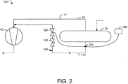
- the oil line control system 100 may include a suction header oil return line 110.
- the suction header oil return line 110 may extend from the suction header 35 to one or more of the compressors 40 or to the refrigeration line 17 upstream of the compressors.
- the suction oil return line 110 may include a solenoid valve 120 thereon.
- the solenoid valve 120 may be a conventional on/off type flow control valve. Other types of flow control valves may be used herein.
- the solenoid valve 120 normally may be in the open position.
- the suction header oil return line 110 also may include a ball valve 130 or other type of manual control valve.
- the ball valve 130 may be manually operated to open and close the suction header oil return line 110 as needed.
- the suction header oil return line 110 also may include a Schrader valve 140.
- the Schrader valve 140 may be a conventional pneumatic valve so as to clear the line via air pressure if necessary. Other type of clearing access ports and clearing devices also may be used herein.
- the oil line control system 100 also may include a temperature sensor 150.
- the temperature sensor 150 may be positioned on the suction oil return line 110 or elsewhere to determine the temperature of the refrigerant 15 and/or changes in the temperature of the refrigerant 15.
- the temperature sensor 150 also may be located inside the suction header 35 or along the exterior thereof.
- the temperature sensor 150 may be of conventional design. More than one temperature sensor 150 may be used herein.
- the temperature sensor 150 may be in communication with the solenoid valve 120 and a controller 160.
- the controller 160 may be any type of programmable logic device.
- the controller 160 may be local or remote. Other components and other configurations may be used herein.
- the oil line control system 100 thus prevents damage to the compressors 40 if liquid refrigerant 15 in the suction header 35 enters the suction header oil return line 110. If the liquid refrigerant 15 enters the suction header oil return line 110, the temperature sensor 150 provides an alarm triggered by a lower than normal temperature therein. A predetermined temperature may be used and/or the temperature may depend upon other types of operational parameters. The solenoid valve 120 thus closes to prevent the liquid refrigerant 15 from flowing to the suction port 45 of the compressor 40. Similarly, the controller 160 may reopen the solenoid valve 120 and the suction header oil return line 110 when the temperature sensor 150 indicates a temperature increase. Such a temperature increase may indicate that the refrigerant 15 has boiled off.
- a predetermined temperature may be used and/or the temperature may depend upon other types of operational parameters.
- the oil line control system 100 then may return to normal operation.
- Different types of heating sources such as an electric heater, a hot gas bypass heater, and the like, also may be employed to assist in boiling off the liquid refrigerant 15 in the suction header 35.
- Other components and other configurations may be used herein.
Landscapes
- Engineering & Computer Science (AREA)
- Physics & Mathematics (AREA)
- Mechanical Engineering (AREA)
- Thermal Sciences (AREA)
- General Engineering & Computer Science (AREA)
- Chemical & Material Sciences (AREA)
- Analytical Chemistry (AREA)
- Power Engineering (AREA)
- Air Conditioning Control Device (AREA)
Abstract
Description
- The present application and the resultant patent relate generally to refrigeration systems and more particularly relate to refrigeration systems including an oil line control system so as to automatically shut off an oil return line when liquid refrigerant floods a suction header and the like so as to prevent compressor damage therein.
- Modern air conditioning and refrigeration systems provide cooling, ventilation, and humidity control for all or part of a climate controlled area such as a refrigerator, a cooler, a building, and the like. Generally described, a conventional refrigeration cycle includes four basic stages to provide cooling. First, a vapor refrigerant is compressed within one or more compressors at high pressure and high temperature. Second, the compressed vapor is cooled within a condenser by heat exchange with ambient air drawn or blown across a condenser coil by a fan and the like. Third, the liquid refrigerant is passed through an expansion device that reduces both the pressure and the temperature of the liquid refrigerant. The liquid refrigerant is then pumped within the climate controlled area to one or more evaporators. The liquid refrigerant absorbs heat from the surroundings in an evaporator coil as the liquid refrigerant evaporates to a vapor. Finally, the vapor refrigerant returns to the compressor and the cycle repeats. Various alternatives on this basic refrigeration cycle are known and also may be used herein.
- Current design trends in refrigeration systems focus on increased efficiency, reduced energy consumption, and other types of environmentally friendly improvements. Similarly, other design goals may focus on reducing the overall complexity and costs typically found in modern refrigeration systems. There is thus a desire for improved refrigeration systems with respect to efficiency, energy usage, complexity, and costs.
- The present application and the resultant patent thus provide a refrigeration system. The refrigeration system may include a suction header, a compressor, a suction header oil return line in communication with the suction header and the compressor, and an oil line control system. The oil line control system may include a sensor and a valve to open and shut the suction header oil return line in response to the sensor. The sensor may be a temperature sensor that detects the presence of a cooler liquid refrigerant therein.
- The present application and the resultant patent further provide a method of protecting a compressor from a flow of liquid refrigerant. The method may include the steps of monitoring a temperature of a fluid in an oil return line extending between a suction header and the compressor, determining a temperature drop in the fluid in the oil return line, and closing the oil return line until the temperature of the fluid in the oil return line increases.
- The present application and the resultant patent further provide a refrigeration system. The refrigeration system may include a suction header, a compressor, a suction header oil return line in communication with the suction header and the compressor, a temperature sensor positioned about the suction header oil return line, and a valve to open and shut the suction header oil return line in response to the temperature sensor.
- These and other features and improvements of the present application and the resultant patent will become apparent to one of ordinary skill in the art upon review of the following detailed description when taken in conjunction with the several drawings and the appended claims.
-
-
Fig. 1 is a schematic diagram of a known refrigeration system with an oil return line. -
Fig. 2 is a schematic diagram of an oil line control system as may be described herein. - Referring now to the drawings, in which like numerals refer to like elements throughout the several views,
Fig. 1 shows an example of knownrefrigeration system 10. Therefrigeration system 10 may be used to cool any type of a climate controlled area or a refrigerated space. The refrigerated space may be a refrigerator, a cooler, a building, and the like. Therefrigeration system 10 may include a flow of arefrigerant 15. Therefrigerant 15 may include conventional refrigerants such as hydrofluorocarbons, carbon dioxide, ammonia, and the like. Any type of refrigerant may be used herein. - The
refrigeration system 10 may include anevaporator assembly 20. Theevaporator assembly 20 may include one ormore evaporator coils 25 and anevaporator fan 30. Theevaporator assembly 20 may be positioned within or adjacent to the refrigerated space to provide cooling therein. Therefrigeration system 10 may include asuction header 35. Thesuction header 35 may store and distribute therefrigerant 15 as required. Thesuction header 35 may flow therefrigerant 15 to an accumulator or directly to one ormore compressors 40 via one ormore refrigerant lines 17. Specifically, thesuction header 35 may be in communication with asuction port 45 on eachcompressor 40. Thecompressors 40 compress the flow ofrefrigerant 15 and forward the flow to acondenser assembly 50 via adischarge port 55. Thecondenser assembly 50 may include on ormore condenser coils 60 and acondenser fan 65. Thecondenser fan 65 pulls ambient air over thecondenser coils 60 for heat exchange with the refrigerant. Therefrigerant 15 then may flow to an expansion valve 70 before being returned to theevaporator assembly 20 so as to repeat the cycle herein. Therefrigeration system 10 described herein is for the purpose of example only. Many other types of refrigeration systems, refrigeration cycles, and refrigeration components may be used herein. - The
compressors 40 herein may require a source of oil in communication with the flow of therefrigerant 15. Anoil separator 75 may be positioned downstream of thecompressors 40. Any oil that may be trapped in the refrigerant vapor downstream of thecompressors 40 may be removed therein. A removed flow ofoil 80 then may be returned to thecompressors 40 via anoil return line 85. Moreover, anyoil 80 that remains in the flow of therefrigerant 15 may eventually settle within thesuction header 35. A suctionoil return line 90 thus may return theoil 80 to thecompressors 40 or to therefrigeration line 17 upstream of thecompressors 40. Other components and other configurations may be used herein. -
Fig. 2 shows an oilline control system 100 as may be described herein. The oilline control system 100 may include a suction headeroil return line 110. The suction headeroil return line 110 may extend from thesuction header 35 to one or more of thecompressors 40 or to therefrigeration line 17 upstream of the compressors. The suctionoil return line 110 may include asolenoid valve 120 thereon. Thesolenoid valve 120 may be a conventional on/off type flow control valve. Other types of flow control valves may be used herein. Thesolenoid valve 120 normally may be in the open position. The suction headeroil return line 110 also may include aball valve 130 or other type of manual control valve. Theball valve 130 may be manually operated to open and close the suction headeroil return line 110 as needed. The suction headeroil return line 110 also may include aSchrader valve 140. TheSchrader valve 140 may be a conventional pneumatic valve so as to clear the line via air pressure if necessary. Other type of clearing access ports and clearing devices also may be used herein. - The oil
line control system 100 also may include atemperature sensor 150. Thetemperature sensor 150 may be positioned on the suctionoil return line 110 or elsewhere to determine the temperature of the refrigerant 15 and/or changes in the temperature of the refrigerant 15. Thetemperature sensor 150 also may be located inside thesuction header 35 or along the exterior thereof. Thetemperature sensor 150 may be of conventional design. More than onetemperature sensor 150 may be used herein. Thetemperature sensor 150 may be in communication with thesolenoid valve 120 and acontroller 160. Thecontroller 160 may be any type of programmable logic device. Thecontroller 160 may be local or remote. Other components and other configurations may be used herein. - The oil
line control system 100 thus prevents damage to thecompressors 40 if liquid refrigerant 15 in thesuction header 35 enters the suction headeroil return line 110. If theliquid refrigerant 15 enters the suction headeroil return line 110, thetemperature sensor 150 provides an alarm triggered by a lower than normal temperature therein. A predetermined temperature may be used and/or the temperature may depend upon other types of operational parameters. Thesolenoid valve 120 thus closes to prevent the liquid refrigerant 15 from flowing to thesuction port 45 of thecompressor 40. Similarly, thecontroller 160 may reopen thesolenoid valve 120 and the suction headeroil return line 110 when thetemperature sensor 150 indicates a temperature increase. Such a temperature increase may indicate that the refrigerant 15 has boiled off. Likewise, a predetermined temperature may be used and/or the temperature may depend upon other types of operational parameters. The oilline control system 100 then may return to normal operation. Different types of heating sources, such as an electric heater, a hot gas bypass heater, and the like, also may be employed to assist in boiling off the liquid refrigerant 15 in thesuction header 35. Other components and other configurations may be used herein. - It should be apparent that the foregoing relates only to certain embodiments of the present application and the resultant patent. Numerous changes and modifications may be made herein by one of ordinary skill in the art without departing from the general spirit and scope of the invention as defined by the following claims and the equivalents thereof.
Claims (15)
- A refrigeration system, comprising:a suction header;a compressor;a suction header oil return line in communication with the suction header and the compressor; andan oil line control system;wherein the oil line control system comprises a sensor and a valve to open and shut the suction header oil return line in response to the sensor.
- The refrigeration system of claim 1, further comprising a refrigerant line in communication with the compressor and the suction header.
- The refrigeration system of claim 1, wherein the suction header comprises refrigerant therein.
- The refrigeration system of claim 1, wherein the suction header comprises oil therein.
- The refrigeration system of claim 1, wherein the valve comprises a solenoid valve.
- The refrigeration system of claim 1, wherein the sensor comprises a temperature sensor.
- The refrigeration system of claim 1, wherein the oil line control system comprises a control in communication with the valve and the sensor.
- The refrigeration system of claim 1, wherein the oil line control system comprises a manual control valve on the suction header oil return line.
- The refrigeration system of claim 8, wherein the manual control valve comprises a ball valve.
- The refrigeration system of claim 1, wherein the oil line control system comprises a pneumatic valve on the suction header oil return line.
- The refrigeration system of claim 10, wherein the pneumatic valve comprises a Schrader valve.
- The refrigeration system of claim 1, further comprising an oil separator downstream of the compressor.
- The refrigeration system of claim 12, further comprising an oil separator return line in communication with the oil separator and the compressor.
- The refrigeration system of claim 1, further comprising a plurality of compressors.
- A method of protecting a compressor from a flow of liquid refrigerant, comprising:monitoring a temperature of a fluid in an oil return line extending between a suction header and the compressor;determining a temperature drop in the fluid in the oil return line; andclosing the oil return line until the temperature of the fluid in the oil return line increases.
Applications Claiming Priority (1)
| Application Number | Priority Date | Filing Date | Title |
|---|---|---|---|
| US14/624,612 US10408513B2 (en) | 2015-02-18 | 2015-02-18 | Oil line control system |
Publications (1)
| Publication Number | Publication Date |
|---|---|
| EP3059523A1 true EP3059523A1 (en) | 2016-08-24 |
Family
ID=55527249
Family Applications (1)
| Application Number | Title | Priority Date | Filing Date |
|---|---|---|---|
| EP16156385.3A Withdrawn EP3059523A1 (en) | 2015-02-18 | 2016-02-18 | Oil line control system |
Country Status (2)
| Country | Link |
|---|---|
| US (1) | US10408513B2 (en) |
| EP (1) | EP3059523A1 (en) |
Families Citing this family (2)
| Publication number | Priority date | Publication date | Assignee | Title |
|---|---|---|---|---|
| CN110360779B (en) * | 2019-07-14 | 2021-07-06 | 南京创维家用电器有限公司 | Liquid impact prevention protection control method for air-cooled refrigerator compressor |
| JP2024011176A (en) * | 2022-07-14 | 2024-01-25 | 三菱重工業株式会社 | Compressor unit and refrigeration system |
Citations (5)
| Publication number | Priority date | Publication date | Assignee | Title |
|---|---|---|---|---|
| US3777509A (en) * | 1972-03-13 | 1973-12-11 | Borg Warner | Oil return system for refrigeration apparatus |
| JPS5250347U (en) * | 1975-10-08 | 1977-04-09 | ||
| DE4140625A1 (en) * | 1991-12-10 | 1993-06-17 | Ilka Maschinenfabrik Halle Gmb | Oil feedback system for compression refrigeration appts. - has regulator responsive to detected temp. difference for closure of control valve in oil feedback line to compressor |
| JP2003279175A (en) * | 2002-03-22 | 2003-10-02 | Mitsubishi Electric Corp | Refrigerating air conditioning system |
| JP2004353904A (en) * | 2003-05-28 | 2004-12-16 | Sanyo Electric Co Ltd | Accumulator and air conditioner |
Family Cites Families (14)
| Publication number | Priority date | Publication date | Assignee | Title |
|---|---|---|---|---|
| US3779035A (en) * | 1971-12-17 | 1973-12-18 | D Kramer | Suction accumulators for refrigeration systems |
| US4068493A (en) * | 1976-03-04 | 1978-01-17 | Kramer Trenton Company | Suction accumulator for refrigeration systems |
| US4503685A (en) | 1982-11-19 | 1985-03-12 | Hussmann Corporation | Oil control valve for refrigeration system |
| US4589263A (en) | 1984-04-12 | 1986-05-20 | Hussmann Corporation | Multiple compressor oil system |
| US4554795A (en) | 1983-11-14 | 1985-11-26 | Tyler Refrigeration Corporation | Compressor oil return system for refrigeration apparatus and method |
| US4866951A (en) * | 1988-08-05 | 1989-09-19 | Evap, Inc. | Vehicle air conditioning accumulator with adjustable connector |
| US5327735A (en) * | 1991-10-28 | 1994-07-12 | The Youngstown Research & Development Co. | Refrigerant reclaiming and recycling system with evaporator chill bath |
| US5437162A (en) * | 1993-07-21 | 1995-08-01 | Eden; Herbert R. | Closed loop oil service system for AC or refrigerant compressor units |
| JP3439178B2 (en) * | 1993-12-28 | 2003-08-25 | 三菱電機株式会社 | Refrigeration cycle device |
| US6263694B1 (en) * | 2000-04-20 | 2001-07-24 | James G. Boyko | Compressor protection device for refrigeration systems |
| JP3719246B2 (en) * | 2003-01-10 | 2005-11-24 | ダイキン工業株式会社 | Refrigeration apparatus and refrigerant amount detection method for refrigeration apparatus |
| KR100556773B1 (en) * | 2003-11-05 | 2006-03-10 | 엘지전자 주식회사 | Oil return apparatus for accumulator of air conditioner and oil return method thereof |
| US7810351B2 (en) * | 2005-03-02 | 2010-10-12 | Westermeyer Gary W | Multiple outlet vertical oil separator |
| JP5169295B2 (en) * | 2007-03-27 | 2013-03-27 | ダイキン工業株式会社 | Refrigeration equipment |
-
2015
- 2015-02-18 US US14/624,612 patent/US10408513B2/en active Active
-
2016
- 2016-02-18 EP EP16156385.3A patent/EP3059523A1/en not_active Withdrawn
Patent Citations (5)
| Publication number | Priority date | Publication date | Assignee | Title |
|---|---|---|---|---|
| US3777509A (en) * | 1972-03-13 | 1973-12-11 | Borg Warner | Oil return system for refrigeration apparatus |
| JPS5250347U (en) * | 1975-10-08 | 1977-04-09 | ||
| DE4140625A1 (en) * | 1991-12-10 | 1993-06-17 | Ilka Maschinenfabrik Halle Gmb | Oil feedback system for compression refrigeration appts. - has regulator responsive to detected temp. difference for closure of control valve in oil feedback line to compressor |
| JP2003279175A (en) * | 2002-03-22 | 2003-10-02 | Mitsubishi Electric Corp | Refrigerating air conditioning system |
| JP2004353904A (en) * | 2003-05-28 | 2004-12-16 | Sanyo Electric Co Ltd | Accumulator and air conditioner |
Also Published As
| Publication number | Publication date |
|---|---|
| US10408513B2 (en) | 2019-09-10 |
| US20160238293A1 (en) | 2016-08-18 |
Similar Documents
| Publication | Publication Date | Title |
|---|---|---|
| WO2014024838A1 (en) | Cascade refrigeration equipment | |
| US11199342B2 (en) | Air conditioner | |
| US20170328604A1 (en) | A method for operating a vapour compression system with a receiver | |
| US20130091885A1 (en) | Air conditioner | |
| CN109790995B (en) | Air conditioner | |
| EP2837900B1 (en) | Air-conditioning device | |
| WO2021039087A1 (en) | Heat source unit and refrigeration device | |
| EP2837901A1 (en) | Cooling system and control method thereof | |
| US20190360725A1 (en) | Refrigeration apparatus | |
| US11092369B2 (en) | Integrated suction header assembly | |
| EP3361190A1 (en) | Refrigeration cycle device and control method for determination of leaks in bypass valve of refrigeration cycle device | |
| US20160252290A1 (en) | Heat-source-side unit and air-conditioning apparatus | |
| JP2013181736A (en) | Refrigerating apparatus for container | |
| KR102082881B1 (en) | Multi-air conditioner for heating and cooling operations at the same time | |
| WO2015060384A1 (en) | Refrigeration device | |
| US20170074559A1 (en) | Air conditioner and cooling receiver of air conditioner | |
| EP3059523A1 (en) | Oil line control system | |
| CN110319542B (en) | Unloading start-stop control method of large-displacement variable-frequency multi-split system | |
| KR20190041091A (en) | Air Conditioner | |
| KR101151529B1 (en) | Refrigerant system | |
| EP3059522A2 (en) | Transport refrigeration unit | |
| KR20100120323A (en) | Chiller system | |
| KR20130090133A (en) | Air conditoner | |
| US11092370B2 (en) | Systems and methods for low load compressor operations | |
| CN105308395B (en) | Refrigerating plant |
Legal Events
| Date | Code | Title | Description |
|---|---|---|---|
| PUAI | Public reference made under article 153(3) epc to a published international application that has entered the european phase |
Free format text: ORIGINAL CODE: 0009012 |
|
| AK | Designated contracting states |
Kind code of ref document: A1 Designated state(s): AL AT BE BG CH CY CZ DE DK EE ES FI FR GB GR HR HU IE IS IT LI LT LU LV MC MK MT NL NO PL PT RO RS SE SI SK SM TR |
|
| AX | Request for extension of the european patent |
Extension state: BA ME |
|
| STAA | Information on the status of an ep patent application or granted ep patent |
Free format text: STATUS: REQUEST FOR EXAMINATION WAS MADE |
|
| 17P | Request for examination filed |
Effective date: 20170223 |
|
| RBV | Designated contracting states (corrected) |
Designated state(s): AL AT BE BG CH CY CZ DE DK EE ES FI FR GB GR HR HU IE IS IT LI LT LU LV MC MK MT NL NO PL PT RO RS SE SI SK SM TR |
|
| STAA | Information on the status of an ep patent application or granted ep patent |
Free format text: STATUS: EXAMINATION IS IN PROGRESS |
|
| 17Q | First examination report despatched |
Effective date: 20210224 |
|
| STAA | Information on the status of an ep patent application or granted ep patent |
Free format text: STATUS: THE APPLICATION HAS BEEN WITHDRAWN |
|
| 18W | Application withdrawn |
Effective date: 20210825 |