EP3054042B2 - Method for manufacturing a laminate and laminate - Google Patents
Method for manufacturing a laminate and laminate Download PDFInfo
- Publication number
- EP3054042B2 EP3054042B2 EP15153790.9A EP15153790A EP3054042B2 EP 3054042 B2 EP3054042 B2 EP 3054042B2 EP 15153790 A EP15153790 A EP 15153790A EP 3054042 B2 EP3054042 B2 EP 3054042B2
- Authority
- EP
- European Patent Office
- Prior art keywords
- spunbond layer
- filaments
- laminate
- continuous filaments
- spunbond
- Prior art date
- Legal status (The legal status is an assumption and is not a legal conclusion. Google has not performed a legal analysis and makes no representation as to the accuracy of the status listed.)
- Active
Links
- 238000000034 method Methods 0.000 title claims description 29
- 238000004519 manufacturing process Methods 0.000 title claims description 13
- -1 polypropylene Polymers 0.000 claims description 55
- 239000004743 Polypropylene Substances 0.000 claims description 41
- 229920001155 polypropylene Polymers 0.000 claims description 41
- 238000002788 crimping Methods 0.000 claims description 23
- 238000007596 consolidation process Methods 0.000 claims description 18
- 230000000052 comparative effect Effects 0.000 claims description 14
- 239000004698 Polyethylene Substances 0.000 claims description 13
- 229920000573 polyethylene Polymers 0.000 claims description 13
- 229920000098 polyolefin Polymers 0.000 claims description 12
- 238000005056 compaction Methods 0.000 claims description 7
- 239000000463 material Substances 0.000 claims description 3
- 238000001816 cooling Methods 0.000 description 14
- 239000004745 nonwoven fabric Substances 0.000 description 11
- 229920000642 polymer Polymers 0.000 description 7
- 229920005629 polypropylene homopolymer Polymers 0.000 description 7
- 239000000155 melt Substances 0.000 description 6
- 239000000203 mixture Substances 0.000 description 5
- 238000009826 distribution Methods 0.000 description 4
- 230000007423 decrease Effects 0.000 description 3
- 239000000835 fiber Substances 0.000 description 3
- 238000005259 measurement Methods 0.000 description 3
- 239000002994 raw material Substances 0.000 description 3
- 238000000151 deposition Methods 0.000 description 2
- 238000002844 melting Methods 0.000 description 2
- 239000011347 resin Substances 0.000 description 2
- 229920005989 resin Polymers 0.000 description 2
- 238000009987 spinning Methods 0.000 description 2
- 239000012815 thermoplastic material Substances 0.000 description 2
- 239000004952 Polyamide Substances 0.000 description 1
- 230000002902 bimodal effect Effects 0.000 description 1
- 238000005266 casting Methods 0.000 description 1
- 229920001577 copolymer Polymers 0.000 description 1
- 238000000691 measurement method Methods 0.000 description 1
- 229920002647 polyamide Polymers 0.000 description 1
- 229920000139 polyethylene terephthalate Polymers 0.000 description 1
- 239000005020 polyethylene terephthalate Substances 0.000 description 1
- 229920002959 polymer blend Polymers 0.000 description 1
- 229920005606 polypropylene copolymer Polymers 0.000 description 1
- 230000036316 preload Effects 0.000 description 1
- QQONPFPTGQHPMA-UHFFFAOYSA-N propylene Natural products CC=C QQONPFPTGQHPMA-UHFFFAOYSA-N 0.000 description 1
- 125000004805 propylene group Chemical group [H]C([H])([H])C([H])([*:1])C([H])([H])[*:2] 0.000 description 1
- 230000000284 resting effect Effects 0.000 description 1
- 238000004621 scanning probe microscopy Methods 0.000 description 1
- 238000005728 strengthening Methods 0.000 description 1
- 229920001169 thermoplastic Polymers 0.000 description 1
- 239000004416 thermosoftening plastic Substances 0.000 description 1
Images
Classifications
-
- B—PERFORMING OPERATIONS; TRANSPORTING
- B32—LAYERED PRODUCTS
- B32B—LAYERED PRODUCTS, i.e. PRODUCTS BUILT-UP OF STRATA OF FLAT OR NON-FLAT, e.g. CELLULAR OR HONEYCOMB, FORM
- B32B5/00—Layered products characterised by the non- homogeneity or physical structure, i.e. comprising a fibrous, filamentary, particulate or foam layer; Layered products characterised by having a layer differing constitutionally or physically in different parts
- B32B5/22—Layered products characterised by the non- homogeneity or physical structure, i.e. comprising a fibrous, filamentary, particulate or foam layer; Layered products characterised by having a layer differing constitutionally or physically in different parts characterised by the presence of two or more layers which are next to each other and are fibrous, filamentary, formed of particles or foamed
- B32B5/24—Layered products characterised by the non- homogeneity or physical structure, i.e. comprising a fibrous, filamentary, particulate or foam layer; Layered products characterised by having a layer differing constitutionally or physically in different parts characterised by the presence of two or more layers which are next to each other and are fibrous, filamentary, formed of particles or foamed one layer being a fibrous or filamentary layer
- B32B5/26—Layered products characterised by the non- homogeneity or physical structure, i.e. comprising a fibrous, filamentary, particulate or foam layer; Layered products characterised by having a layer differing constitutionally or physically in different parts characterised by the presence of two or more layers which are next to each other and are fibrous, filamentary, formed of particles or foamed one layer being a fibrous or filamentary layer another layer next to it also being fibrous or filamentary
-
- B—PERFORMING OPERATIONS; TRANSPORTING
- B32—LAYERED PRODUCTS
- B32B—LAYERED PRODUCTS, i.e. PRODUCTS BUILT-UP OF STRATA OF FLAT OR NON-FLAT, e.g. CELLULAR OR HONEYCOMB, FORM
- B32B38/00—Ancillary operations in connection with laminating processes
- B32B38/0036—Heat treatment
- B32B38/004—Heat treatment by physically contacting the layers, e.g. by the use of heated platens or rollers
-
- D—TEXTILES; PAPER
- D04—BRAIDING; LACE-MAKING; KNITTING; TRIMMINGS; NON-WOVEN FABRICS
- D04H—MAKING TEXTILE FABRICS, e.g. FROM FIBRES OR FILAMENTARY MATERIAL; FABRICS MADE BY SUCH PROCESSES OR APPARATUS, e.g. FELTS, NON-WOVEN FABRICS; COTTON-WOOL; WADDING ; NON-WOVEN FABRICS FROM STAPLE FIBRES, FILAMENTS OR YARNS, BONDED WITH AT LEAST ONE WEB-LIKE MATERIAL DURING THEIR CONSOLIDATION
- D04H3/00—Non-woven fabrics formed wholly or mainly of yarns or like filamentary material of substantial length
- D04H3/08—Non-woven fabrics formed wholly or mainly of yarns or like filamentary material of substantial length characterised by the method of strengthening or consolidating
- D04H3/14—Non-woven fabrics formed wholly or mainly of yarns or like filamentary material of substantial length characterised by the method of strengthening or consolidating with bonds between thermoplastic yarns or filaments produced by welding
- D04H3/147—Composite yarns or filaments
-
- B—PERFORMING OPERATIONS; TRANSPORTING
- B29—WORKING OF PLASTICS; WORKING OF SUBSTANCES IN A PLASTIC STATE IN GENERAL
- B29C—SHAPING OR JOINING OF PLASTICS; SHAPING OF MATERIAL IN A PLASTIC STATE, NOT OTHERWISE PROVIDED FOR; AFTER-TREATMENT OF THE SHAPED PRODUCTS, e.g. REPAIRING
- B29C70/00—Shaping composites, i.e. plastics material comprising reinforcements, fillers or preformed parts, e.g. inserts
- B29C70/04—Shaping composites, i.e. plastics material comprising reinforcements, fillers or preformed parts, e.g. inserts comprising reinforcements only, e.g. self-reinforcing plastics
- B29C70/28—Shaping operations therefor
- B29C70/40—Shaping or impregnating by compression not applied
- B29C70/50—Shaping or impregnating by compression not applied for producing articles of indefinite length, e.g. prepregs, sheet moulding compounds [SMC] or cross moulding compounds [XMC]
- B29C70/504—Shaping or impregnating by compression not applied for producing articles of indefinite length, e.g. prepregs, sheet moulding compounds [SMC] or cross moulding compounds [XMC] using rollers or pressure bands
- B29C70/508—Shaping or impregnating by compression not applied for producing articles of indefinite length, e.g. prepregs, sheet moulding compounds [SMC] or cross moulding compounds [XMC] using rollers or pressure bands and first forming a mat composed of short fibres
-
- B—PERFORMING OPERATIONS; TRANSPORTING
- B32—LAYERED PRODUCTS
- B32B—LAYERED PRODUCTS, i.e. PRODUCTS BUILT-UP OF STRATA OF FLAT OR NON-FLAT, e.g. CELLULAR OR HONEYCOMB, FORM
- B32B5/00—Layered products characterised by the non- homogeneity or physical structure, i.e. comprising a fibrous, filamentary, particulate or foam layer; Layered products characterised by having a layer differing constitutionally or physically in different parts
- B32B5/02—Layered products characterised by the non- homogeneity or physical structure, i.e. comprising a fibrous, filamentary, particulate or foam layer; Layered products characterised by having a layer differing constitutionally or physically in different parts characterised by structural features of a fibrous or filamentary layer
- B32B5/022—Non-woven fabric
-
- B—PERFORMING OPERATIONS; TRANSPORTING
- B32—LAYERED PRODUCTS
- B32B—LAYERED PRODUCTS, i.e. PRODUCTS BUILT-UP OF STRATA OF FLAT OR NON-FLAT, e.g. CELLULAR OR HONEYCOMB, FORM
- B32B5/00—Layered products characterised by the non- homogeneity or physical structure, i.e. comprising a fibrous, filamentary, particulate or foam layer; Layered products characterised by having a layer differing constitutionally or physically in different parts
- B32B5/02—Layered products characterised by the non- homogeneity or physical structure, i.e. comprising a fibrous, filamentary, particulate or foam layer; Layered products characterised by having a layer differing constitutionally or physically in different parts characterised by structural features of a fibrous or filamentary layer
- B32B5/06—Layered products characterised by the non- homogeneity or physical structure, i.e. comprising a fibrous, filamentary, particulate or foam layer; Layered products characterised by having a layer differing constitutionally or physically in different parts characterised by structural features of a fibrous or filamentary layer characterised by a fibrous or filamentary layer mechanically connected, e.g. by needling to another layer, e.g. of fibres, of paper
-
- B—PERFORMING OPERATIONS; TRANSPORTING
- B32—LAYERED PRODUCTS
- B32B—LAYERED PRODUCTS, i.e. PRODUCTS BUILT-UP OF STRATA OF FLAT OR NON-FLAT, e.g. CELLULAR OR HONEYCOMB, FORM
- B32B5/00—Layered products characterised by the non- homogeneity or physical structure, i.e. comprising a fibrous, filamentary, particulate or foam layer; Layered products characterised by having a layer differing constitutionally or physically in different parts
- B32B5/02—Layered products characterised by the non- homogeneity or physical structure, i.e. comprising a fibrous, filamentary, particulate or foam layer; Layered products characterised by having a layer differing constitutionally or physically in different parts characterised by structural features of a fibrous or filamentary layer
- B32B5/08—Layered products characterised by the non- homogeneity or physical structure, i.e. comprising a fibrous, filamentary, particulate or foam layer; Layered products characterised by having a layer differing constitutionally or physically in different parts characterised by structural features of a fibrous or filamentary layer the fibres or filaments of a layer being of different substances, e.g. conjugate fibres, mixture of different fibres
-
- B—PERFORMING OPERATIONS; TRANSPORTING
- B32—LAYERED PRODUCTS
- B32B—LAYERED PRODUCTS, i.e. PRODUCTS BUILT-UP OF STRATA OF FLAT OR NON-FLAT, e.g. CELLULAR OR HONEYCOMB, FORM
- B32B5/00—Layered products characterised by the non- homogeneity or physical structure, i.e. comprising a fibrous, filamentary, particulate or foam layer; Layered products characterised by having a layer differing constitutionally or physically in different parts
- B32B5/02—Layered products characterised by the non- homogeneity or physical structure, i.e. comprising a fibrous, filamentary, particulate or foam layer; Layered products characterised by having a layer differing constitutionally or physically in different parts characterised by structural features of a fibrous or filamentary layer
- B32B5/10—Layered products characterised by the non- homogeneity or physical structure, i.e. comprising a fibrous, filamentary, particulate or foam layer; Layered products characterised by having a layer differing constitutionally or physically in different parts characterised by structural features of a fibrous or filamentary layer characterised by a fibrous or filamentary layer reinforced with filaments
-
- B—PERFORMING OPERATIONS; TRANSPORTING
- B32—LAYERED PRODUCTS
- B32B—LAYERED PRODUCTS, i.e. PRODUCTS BUILT-UP OF STRATA OF FLAT OR NON-FLAT, e.g. CELLULAR OR HONEYCOMB, FORM
- B32B5/00—Layered products characterised by the non- homogeneity or physical structure, i.e. comprising a fibrous, filamentary, particulate or foam layer; Layered products characterised by having a layer differing constitutionally or physically in different parts
- B32B5/02—Layered products characterised by the non- homogeneity or physical structure, i.e. comprising a fibrous, filamentary, particulate or foam layer; Layered products characterised by having a layer differing constitutionally or physically in different parts characterised by structural features of a fibrous or filamentary layer
- B32B5/12—Layered products characterised by the non- homogeneity or physical structure, i.e. comprising a fibrous, filamentary, particulate or foam layer; Layered products characterised by having a layer differing constitutionally or physically in different parts characterised by structural features of a fibrous or filamentary layer characterised by the relative arrangement of fibres or filaments of different layers, e.g. the fibres or filaments being parallel or perpendicular to each other
-
- D—TEXTILES; PAPER
- D04—BRAIDING; LACE-MAKING; KNITTING; TRIMMINGS; NON-WOVEN FABRICS
- D04H—MAKING TEXTILE FABRICS, e.g. FROM FIBRES OR FILAMENTARY MATERIAL; FABRICS MADE BY SUCH PROCESSES OR APPARATUS, e.g. FELTS, NON-WOVEN FABRICS; COTTON-WOOL; WADDING ; NON-WOVEN FABRICS FROM STAPLE FIBRES, FILAMENTS OR YARNS, BONDED WITH AT LEAST ONE WEB-LIKE MATERIAL DURING THEIR CONSOLIDATION
- D04H1/00—Non-woven fabrics formed wholly or mainly of staple fibres or like relatively short fibres
- D04H1/40—Non-woven fabrics formed wholly or mainly of staple fibres or like relatively short fibres from fleeces or layers composed of fibres without existing or potential cohesive properties
- D04H1/42—Non-woven fabrics formed wholly or mainly of staple fibres or like relatively short fibres from fleeces or layers composed of fibres without existing or potential cohesive properties characterised by the use of certain kinds of fibres insofar as this use has no preponderant influence on the consolidation of the fleece
- D04H1/4374—Non-woven fabrics formed wholly or mainly of staple fibres or like relatively short fibres from fleeces or layers composed of fibres without existing or potential cohesive properties characterised by the use of certain kinds of fibres insofar as this use has no preponderant influence on the consolidation of the fleece using different kinds of webs, e.g. by layering webs
-
- D—TEXTILES; PAPER
- D04—BRAIDING; LACE-MAKING; KNITTING; TRIMMINGS; NON-WOVEN FABRICS
- D04H—MAKING TEXTILE FABRICS, e.g. FROM FIBRES OR FILAMENTARY MATERIAL; FABRICS MADE BY SUCH PROCESSES OR APPARATUS, e.g. FELTS, NON-WOVEN FABRICS; COTTON-WOOL; WADDING ; NON-WOVEN FABRICS FROM STAPLE FIBRES, FILAMENTS OR YARNS, BONDED WITH AT LEAST ONE WEB-LIKE MATERIAL DURING THEIR CONSOLIDATION
- D04H3/00—Non-woven fabrics formed wholly or mainly of yarns or like filamentary material of substantial length
- D04H3/005—Synthetic yarns or filaments
-
- D—TEXTILES; PAPER
- D04—BRAIDING; LACE-MAKING; KNITTING; TRIMMINGS; NON-WOVEN FABRICS
- D04H—MAKING TEXTILE FABRICS, e.g. FROM FIBRES OR FILAMENTARY MATERIAL; FABRICS MADE BY SUCH PROCESSES OR APPARATUS, e.g. FELTS, NON-WOVEN FABRICS; COTTON-WOOL; WADDING ; NON-WOVEN FABRICS FROM STAPLE FIBRES, FILAMENTS OR YARNS, BONDED WITH AT LEAST ONE WEB-LIKE MATERIAL DURING THEIR CONSOLIDATION
- D04H3/00—Non-woven fabrics formed wholly or mainly of yarns or like filamentary material of substantial length
- D04H3/018—Non-woven fabrics formed wholly or mainly of yarns or like filamentary material of substantial length characterised by the shape
-
- B—PERFORMING OPERATIONS; TRANSPORTING
- B29—WORKING OF PLASTICS; WORKING OF SUBSTANCES IN A PLASTIC STATE IN GENERAL
- B29K—INDEXING SCHEME ASSOCIATED WITH SUBCLASSES B29B, B29C OR B29D, RELATING TO MOULDING MATERIALS OR TO MATERIALS FOR MOULDS, REINFORCEMENTS, FILLERS OR PREFORMED PARTS, e.g. INSERTS
- B29K2023/00—Use of polyalkenes or derivatives thereof as moulding material
- B29K2023/04—Polymers of ethylene
- B29K2023/06—PE, i.e. polyethylene
-
- B—PERFORMING OPERATIONS; TRANSPORTING
- B29—WORKING OF PLASTICS; WORKING OF SUBSTANCES IN A PLASTIC STATE IN GENERAL
- B29K—INDEXING SCHEME ASSOCIATED WITH SUBCLASSES B29B, B29C OR B29D, RELATING TO MOULDING MATERIALS OR TO MATERIALS FOR MOULDS, REINFORCEMENTS, FILLERS OR PREFORMED PARTS, e.g. INSERTS
- B29K2023/00—Use of polyalkenes or derivatives thereof as moulding material
- B29K2023/10—Polymers of propylene
- B29K2023/12—PP, i.e. polypropylene
-
- B—PERFORMING OPERATIONS; TRANSPORTING
- B29—WORKING OF PLASTICS; WORKING OF SUBSTANCES IN A PLASTIC STATE IN GENERAL
- B29L—INDEXING SCHEME ASSOCIATED WITH SUBCLASS B29C, RELATING TO PARTICULAR ARTICLES
- B29L2009/00—Layered products
-
- B—PERFORMING OPERATIONS; TRANSPORTING
- B32—LAYERED PRODUCTS
- B32B—LAYERED PRODUCTS, i.e. PRODUCTS BUILT-UP OF STRATA OF FLAT OR NON-FLAT, e.g. CELLULAR OR HONEYCOMB, FORM
- B32B2250/00—Layers arrangement
- B32B2250/02—2 layers
-
- B—PERFORMING OPERATIONS; TRANSPORTING
- B32—LAYERED PRODUCTS
- B32B—LAYERED PRODUCTS, i.e. PRODUCTS BUILT-UP OF STRATA OF FLAT OR NON-FLAT, e.g. CELLULAR OR HONEYCOMB, FORM
- B32B2250/00—Layers arrangement
- B32B2250/20—All layers being fibrous or filamentary
-
- B—PERFORMING OPERATIONS; TRANSPORTING
- B32—LAYERED PRODUCTS
- B32B—LAYERED PRODUCTS, i.e. PRODUCTS BUILT-UP OF STRATA OF FLAT OR NON-FLAT, e.g. CELLULAR OR HONEYCOMB, FORM
- B32B2262/00—Composition or structural features of fibres which form a fibrous or filamentary layer or are present as additives
- B32B2262/02—Synthetic macromolecular fibres
- B32B2262/0253—Polyolefin fibres
-
- B—PERFORMING OPERATIONS; TRANSPORTING
- B32—LAYERED PRODUCTS
- B32B—LAYERED PRODUCTS, i.e. PRODUCTS BUILT-UP OF STRATA OF FLAT OR NON-FLAT, e.g. CELLULAR OR HONEYCOMB, FORM
- B32B2262/00—Composition or structural features of fibres which form a fibrous or filamentary layer or are present as additives
- B32B2262/12—Conjugate fibres, e.g. core/sheath or side-by-side
-
- B—PERFORMING OPERATIONS; TRANSPORTING
- B32—LAYERED PRODUCTS
- B32B—LAYERED PRODUCTS, i.e. PRODUCTS BUILT-UP OF STRATA OF FLAT OR NON-FLAT, e.g. CELLULAR OR HONEYCOMB, FORM
- B32B2262/00—Composition or structural features of fibres which form a fibrous or filamentary layer or are present as additives
- B32B2262/14—Mixture of at least two fibres made of different materials
-
- B—PERFORMING OPERATIONS; TRANSPORTING
- B32—LAYERED PRODUCTS
- B32B—LAYERED PRODUCTS, i.e. PRODUCTS BUILT-UP OF STRATA OF FLAT OR NON-FLAT, e.g. CELLULAR OR HONEYCOMB, FORM
- B32B2305/00—Condition, form or state of the layers or laminate
- B32B2305/10—Fibres of continuous length
- B32B2305/20—Fibres of continuous length in the form of a non-woven mat
-
- B—PERFORMING OPERATIONS; TRANSPORTING
- B32—LAYERED PRODUCTS
- B32B—LAYERED PRODUCTS, i.e. PRODUCTS BUILT-UP OF STRATA OF FLAT OR NON-FLAT, e.g. CELLULAR OR HONEYCOMB, FORM
- B32B2307/00—Properties of the layers or laminate
- B32B2307/50—Properties of the layers or laminate having particular mechanical properties
- B32B2307/546—Flexural strength; Flexion stiffness
-
- B—PERFORMING OPERATIONS; TRANSPORTING
- B32—LAYERED PRODUCTS
- B32B—LAYERED PRODUCTS, i.e. PRODUCTS BUILT-UP OF STRATA OF FLAT OR NON-FLAT, e.g. CELLULAR OR HONEYCOMB, FORM
- B32B2307/00—Properties of the layers or laminate
- B32B2307/70—Other properties
- B32B2307/732—Dimensional properties
-
- B—PERFORMING OPERATIONS; TRANSPORTING
- B32—LAYERED PRODUCTS
- B32B—LAYERED PRODUCTS, i.e. PRODUCTS BUILT-UP OF STRATA OF FLAT OR NON-FLAT, e.g. CELLULAR OR HONEYCOMB, FORM
- B32B2555/00—Personal care
- B32B2555/02—Diapers or napkins
Definitions
- the invention relates to a method for producing a laminate with at least two layers of spunbonded nonwoven fabric made of continuous filaments, in particular continuous filaments made of thermoplastic material.
- the subject matter of the invention is also a laminate with at least two layers of spunbonded nonwoven fabric made from continuous filaments.
- - Continuous filaments are known to differ from staple fibers, which have much shorter lengths of, for example, 10 mm to 60 mm, due to their quasi-endless length. It is within the scope of the invention that the endless filaments for the spunbonded layers of the laminate according to the invention are produced with at least one spinning device or with at least one spinnerette.
- Spunbonded nonwoven laminates or spunbonded nonwovens with sufficient softness are particularly desirable for hygiene applications. It is known that the softness of a spunbonded nonwoven can be increased by using latently crimping continuous filaments.
- the WO 02/052085 A2 describes, for example, a nonwoven laminate of fibrous layers combining layers of higher crimp filaments and lower crimp filaments.
- the invention is based on the technical problem of specifying a method of the type mentioned at the beginning, with which the production of a laminate from spunbonded layers is possible, the laminate being characterized on the one hand by a high level of softness and bulkiness and on the other hand by sufficient rigidity and strength or tensile strength excellent.
- the invention is also based on the technical problem of specifying a corresponding laminate of spunbonded nonwoven layers.
- the invention teaches a method for producing a laminate according to patent claim 1.
- the total thickness d of the laminate is less than 1.5 mm, preferably less than 1 mm.
- a particularly preferred embodiment of the invention is characterized in that the total thickness d of the laminate is 0.2 mm to 1 mm, recommended 0.3 mm to 0.8 mm.
- the total thickness d of the laminate is measured according to DIN EN ISO 9073-2 (February 1997), specifically according to measurement method 5.1 for normal non-woven fabrics.
- a round bearing surface of 2500 mm 2 is bumplessly against with a pressure of 0.5 kPa pressed the laminate sample lying on a reference plate. 10 seconds after the first contact of the support surface with the laminate, the distance between the two plates is measured as the total thickness d of the laminate.
- the lower spunbonded nonwoven layer means a spunbonded nonwoven layer made of continuous filaments laid down first or earlier
- the upper spunbonded nonwoven layer on the other hand, means a spunbonded nonwoven layer made of continuous filaments laid down afterwards or later on the lower spunbonded nonwoven layer.
- the at least one first lower spunbonded nonwoven layer and the at least one second upper spunbonded nonwoven layer are produced by the spunbond process or as spunbond layers.
- the continuous filaments are each first spun from a spinning head or from a spinneret.
- the spun continuous filaments are expediently then cooled in a cooling chamber and stretched in a stretching device. The cooling and stretching takes place in particular in a combined cooling and stretching unit.
- the continuous filaments be stretched as aerodynamic stretching.
- the unit consisting of the cooling chamber and the stretching device or the combined cooling and stretching unit—apart from the air supply in the cooling chamber or cooling unit— is designed as a closed system. This means that in this unit there is no further air supply apart from the air supply mentioned in the cooling chamber or cooling unit.
- This embodiment of the closed system has proven particularly useful for the production of a laminate according to the invention.
- the cooled and stretched continuous filaments for the two spunbonded layers are guided through at least one diffuser and then deposited on a tray, in particular on a tray sieve belt.
- the endless filaments are first for the first lower spunbonded nonwoven layer and then the continuous filaments for the second upper spunbonded nonwoven layer are deposited on the tray or on the tray sieve belt.
- the endless filaments for the second upper spunbonded nonwoven layer could first be deposited on the deposit or on the depositing sieve belt and then the endless filaments of the first lower spunbonded nonwoven web could be deposited on the deposit or on the depositing sieve belt.
- at least one meltblown layer made of meltblown fibers is arranged between the spunbonded layers (or spunbond layers). It is also within the scope of the invention that the at least one meltblown layer has non-crimping meltblown fibers.
- the at least one first lower spunbonded nonwoven layer is compacted or pre-consolidated with at least one hot roller. This results in a compaction or a certain strengthening of the first lower spunbonded nonwoven layer.
- the intention here is to form the first lower spunbonded nonwoven layer as a relatively compact, stiff and tensile layer in comparison to the upper spunbonded nonwoven layer.
- the first lower layer of spun-bonded non-woven material should expediently primarily determine the stability of the entire laminate.
- the thickness of the at least one lower spunbonded nonwoven layer is less than the thickness of the at least one second upper spunbonded nonwoven layer arranged above it.
- the density of the at least one lower spunbonded nonwoven layer is higher or significantly higher than the density of the at least one second upper spunbonded nonwoven layer arranged above it.
- the at least two layers of spunbonded nonwoven are bonded. A pre-consolidation and a final consolidation can take place, or only a final consolidation of the layer aggregate can take place.
- the laminate produced by the process according to the invention is initially distinguished by satisfactory stability or dimensional stability, particularly in the machine direction.
- the laminate is sufficiently compact overall and has sufficient rigidity.
- the laminate is characterized by a relatively high degree of softness and volume.
- the stability and rigidity are primarily ensured by the first lower spunbonded nonwoven layer and the softness or volume by the second upper spunbonded nonwoven layer.
- the laminate also has a good hand and a comparatively low density.
- multicomponent filaments or bicomponent filaments with a symmetrical or central configuration are used for the first lower spunbonded nonwoven layer.
- Multi-component filaments or bi-component filaments with a central or symmetrical core-sheath configuration are particularly preferably used.
- other symmetrical cross-sectional configurations can also be used, for example trilobal configurations and the like.
- the continuous filaments of the first lower spunbonded nonwoven layer consist of monocomponent filaments and/or of the described multicomponent filaments or bicomponent filaments with symmetrical cross-sectional configuration.
- the endless filaments of the first lower spunbonded nonwoven layer consist of at least one polyolefin or essentially of at least one polyolefin.
- the continuous filaments consist of the first lower spunbonded nonwoven layer made of polypropylene and/or polyethylene or essentially made of polypropylene and/or polyethylene.
- at least one component of these continuous filaments consists of at least one polyolefin, preferably polypropylene and/or polyethylene.
- a preferred embodiment of the method according to the invention is characterized in that continuous filaments or multi-component filaments/bi-component filaments with a central core-sheath configuration are used for the first lower spunbonded nonwoven layer.
- the core is expediently made of polypropylene and the jacket is preferably made of polyethylene.
- the recommended weight ratio of core to sheath or polypropylene to polyethylene is 50:50 to 80:20, preferably 70:30.
- the invention is also based on the knowledge that a higher proportion of polypropylene in the core is very helpful or essential for the stability of the laminate according to the invention.
- a particularly recommended embodiment of the invention is characterized in that continuous filaments with natural crimping or with a latent tendency to crimp are used as continuous filaments for the second upper spunbonded nonwoven layer.
- the second upper spunbonded nonwoven layer consists of at least 85% by weight, preferably at least 90% by weight, preferably at least 95% by weight and very preferably at least 98% by weight of continuous filaments with natural crimps or latent crimps ripple.
- an inherent tendency to crimp is caused in these endless filaments by the choice of raw materials and process settings.
- multi-component filaments or bi-component filaments with a side-side configuration are used as endless filaments for the second upper spunbonded nonwoven layer.
- multi-component filaments or bi-component filaments with an acentric or asymmetrical cross-sectional configuration are used, in particular with an acentric or asymmetrical core-sheath configuration.
- the continuous filaments for the second upper spunbonded nonwoven layer preferably consist of at least 85% by weight, expediently at least 90% by weight, preferably at least 95% by weight and very preferably at least 98% by weight of such filaments or multi-component filaments with side-side configuration and/or acentric cross-sectional configuration.
- a preferred embodiment of the invention is characterized in that at least one component of the multicomponent filaments or bicomponent filaments for the second spunbonded nonwoven layer consists of at least one polyolefin or essentially of at least one polyolefin.
- all components of the multi-component filaments or bi-component filaments consist of at least one polyolefin or essentially of at least one polyolefin.
- other raw materials in particular polyamide or polyethylene terephthalate, are also possible for the components.
- the polyolefins are in particular polypropylene and/or polyethylene.
- bicomponent filaments are provided in a side-to-side configuration for the second top spunbonded nonwoven layer and one component is polypropylene and the other component is polyethylene, with a polypropylene to polyethylene ratio of 40:60 to 60:40.
- multicomponent filaments or bicomponent filaments made of at least two different polypropylenes are used as continuous filaments with a latent tendency to curl for the second upper spunbonded nonwoven layer.
- different polypropylenes means in particular polypropylenes with different molar mass distribution and/or different viscosity and/or different isotacticity.
- Polypropylene homopolymers and/or polypropylene copolymers are preferably used as polypropylene.
- bicomponent filaments are used in side-to-side configuration for the endless filaments of the second spunbonded nonwoven layer, and the two components of the bicomponent filaments consist of different polypropylenes.
- multicomponent filaments or bicomponent filaments with an asymmetrical cross-section configuration are used for the continuous filaments of the second upper spunbonded nonwoven layer, and these multicomponent filaments or bicomponent filaments have different polypropylenes for the individual components.
- An embodiment of the invention is characterized in that the second upper spunbonded nonwoven layer is compacted or pre-solidified with the aid of hot air.
- at least one hot air knife can be used for this purpose, which preferably acts on the second upper spunbonded nonwoven layer from above.
- the second upper spunbonded nonwoven layer is compacted or pre-consolidated by means of at least one hot roller (hot outlet roller), the temperature of the first hot roller for compacting or pre-consolidating the first lower spunbonded nonwoven layer being higher than the temperature of the second Hot roller for compaction or pre-consolidation of the second upper spunbonded nonwoven layer.
- hot roller hot outlet roller
- the contact pressure of the first hot roller for compacting or preconsolidating the first lower spunbonded nonwoven layer is higher than the contact pressure of the second hot roller for compacting or preconsolidating the second upper spunbonded nonwoven layer.
- An embodiment of the method according to the invention is characterized in that the temperature of the first hot roller for compacting or pre-consolidation of the first lower spunbonded non-woven layer is 100 to 130 ° C and that the temperature of the second hot roller for compacting or pre-consolidation of the second upper spun-bonded nonwoven layer is 70 to 100 °C. It is within the scope of the invention that the temperatures rise with increased system speed.
- the aggregate of the first lower spunbonded nonwoven layer and the second upper spunbonded nonwoven layer or the layer aggregate for the laminate is finally consolidated, preferably by means of at least one calender.
- final consolidation of the laminate with hot air can also take place.
- a low-melting thermoplastic material in particular low-melting polyethylene—is present as a component in both spunbonded nonwoven layers. In this way, a very effective final consolidation of the laminate can be achieved.
- the method according to the invention or the compaction(s) and/or the preconsolidation(s) and/or consolidation(s) within the scope of the method according to the invention be carried out with the proviso will/are that the thickness d 1 of the first lower spunbonded nonwoven layer in the laminate is 0.1 to 0.3 mm and very preferably 0.15 to 0.2 mm and/or that the thickness d 2 of the second upper spunbonded nonwoven layer in the laminate is 0 .2 to 0.95mm.
- the individual thicknesses d 1 and d 2 of the spunbonded layers in the laminate are measured according to the preferred embodiment as described below. First, as explained above, the total thickness of the laminate is measured according to DIN EN ISO 9073-2 (February 1997).
- the laminate is then compressed to the total thickness of the laminate measured in this way using adjustable surfaces.
- the fleece volume produced in this way is expediently filled with a preferably transparent casting resin and the resin is then allowed to harden.
- the thicknesses of the individual layers can then be measured on the laminate stabilized in this way. For this purpose, for example, after a cut across the surface of the laminate, the individual thicknesses of the layers can be measured optically.
- the individual boundary surfaces and their height positions in the laminate can also be detected in the plan view of the laminate, in particular by means of scanning microscopy.
- the spunbonded nonwoven layers of the laminate according to the invention are produced or deposited with the proviso that the continuous filaments of the first lower spunbonded nonwoven layer are oriented more in the machine direction (MD) than the continuous filaments of the second upper spunbonded nonwoven layer.
- the first lower spunbonded nonwoven layer has a higher rigidity in the machine direction than the second upper spunbonded nonwoven layer of the laminate.
- the first bottom spunbond layer is a more compact, stiffer and denser spunbond layer compared to the second top spunbond layer.
- the first lower spunbonded nonwoven layer expediently determines the stability of the overall product.
- a highly recommended embodiment of the method according to the invention is characterized in that the longitudinal stiffness s L of the finished laminate of the at least one first spunbonded nonwoven layer and the at least one second spunbonded nonwoven layer is 20 to 80%, preferably 40 to 65% of the longitudinal stiffness s V of a comparative nonwoven or Comparative laminates is.
- the comparison nonwoven or the comparison laminate consists of the same material as the at least one first spunbonded nonwoven layer of the laminate and the comparison nonwoven or the comparison laminate has the same weight per unit area as the laminate.
- the comparison fleece or comparison laminate was produced with the same device as the laminate and under the same conditions as the laminate.
- the comparative nonwoven or the comparative laminate has the same number of layers or spunbonded nonwoven layers as the laminate and that all layers or spunbonded nonwoven layers of the comparative nonwoven or comparative laminate are produced under the same conditions as the first spunbonded nonwoven layer of the laminates.
- the preconsolidation or consolidation takes place in the same way as the preconsolidation or consolidation of the first spunbonded nonwoven layer of the laminate.
- the first spunbonded nonwoven layer of the laminate is preconsolidated using a calender with 5 to 22% weld area
- the comparative nonwoven/comparative laminate is also preconsolidated or consolidated using this calender with 5 to 22% weld area.
- the longitudinal stiffness s L of the (finished) laminate and the longitudinal stiffness s V of the comparison fleece or comparison laminate are determined in the context of the invention in particular as the force at 5% elongation of the laminate or the comparison fleece / comparison laminate from the stress-strain curve, with the longitudinal stiffness preferably on the basis weight of the Laminates or the comparison fleece/comparison laminate is normalized, so that the unit of the longitudinal stiffness is (N/5 cm)/(g/m 2 ). - It is within the scope of the invention that the measurement of the longitudinal stiffness or the stress-strain curve is carried out according to EDANA 20.2-89.
- a fleece sample or laminate sample with a width of 50 mm is clamped between two clamping devices at a distance of 100 mm, so that the tested/measured length of the sample is 100 mm.
- This fleece sample or laminate sample is then stretched using a traction machine at a feed rate of 100 mm/min up to a preload of 0.5 N. In this state, the measurement is then reset to zero and the actual measurement begins.
- the traction machine works with a feed or with a traction speed of 200 mm/min.
- the longitudinal stiffness is determined as a force at 5% elongation of the sample from the stress-strain curve.
- the at least two spunbonded nonwoven layers can be produced in an inline method.
- offline production of the spunbonded nonwoven layers is also possible. For example, initially only the at least one first lower spunbonded nonwoven layer can be produced and then at a different time and/or at a different location the at least one upper spunbonded nonwoven layer is placed on the at least one first lower spunbonded nonwoven layer. The laminate of the at least two layers of spunbonded nonwoven is then consolidated. Therefore, both inline production and offline production of the laminate are within the scope of the method according to the invention.
- the invention further teaches a laminate according to patent claim 10.
- the crimping of the spunbonded layers in the laminate increases from bottom to top.
- the crimping of the spunbonded nonwoven layers in the laminate increases from bottom to top, from not latently crimping to latently crimping.
- the density of the spunbonded layers in the laminate decreases from bottom to top.
- the thickness of the spunbonded layers in the laminate increases from bottom to top. In principle, however, the thicknesses can also be identical or similar, or the thickness of the spunbonded nonwoven layers can also decrease from bottom to top in the laminate. According to the highly recommended embodiment, the density of the spunbonded layers in the laminate decreases from bottom to top.
- the thickness ratio of the thickness d 1 of the first lower spunbonded nonwoven layer to the thickness d 2 of the second upper spunbonded nonwoven layer is 1:2 to 1:4.
- the thickness d 2 of the at least one second upper spunbonded nonwoven layer is two to four times greater than the thickness d 1 of the at least one first lower spunbonded nonwoven layer.
- the continuous filaments of the first lower spunbonded nonwoven layer have a linear density of 1.0 to 2.5 den, preferably 1.2 to 2 den.
- the continuous filaments of the second upper spunbonded nonwoven layer have a linear density of 1.8 to 2.5 deniers.
- a particularly recommended embodiment is characterized in that the linear density of the second upper spunbonded nonwoven layer is less than 2.2 den.
- the filament diameter of the continuous filaments of the at least one first lower spunbonded nonwoven layer is less than the filament diameter of the Endless filaments of the at least one second upper spunbonded nonwoven layer. For this reason, the titre of the spunbonded layers in the laminate increases from bottom to top.
- the invention is based on the finding that the method according to the invention can be used to produce a laminate in a simple manner which is characterized on the one hand by high stability or dimensional stability—especially in the machine direction—and on the other hand by relatively high softness or bulkiness. In this respect, an optimal compromise is achieved between stability/strength on the one hand and softness/voluminousness on the other. Furthermore, the invention is based on the knowledge that the at least one first lower spunbonded nonwoven layer ensures the rigidity to a sufficient extent—in particular in the machine direction of the laminate.
- the laminate according to the invention is sufficiently compact, has a good hand and is also characterized by a relatively low overall density.
- the laminate according to the invention can be produced in a relatively simple and inexpensive manner and is also characterized by relatively low costs.
- the laminate according to the invention can be used primarily for hygiene applications, for example for diapers and the like. In principle, however, other possible applications are also conceivable.
- a laminate according to the invention is produced from two layers of spunbonded nonwovens made of polypropylene using a double beam system. Both spunbonded layers are produced using the spunbond process. The two spunbonded layers are expediently produced using the Reicofil method.
- the filaments spun for a spunbonded nonwoven layer are first passed through a cooling chamber, where they are cooled with cooling air and Subsequently introduced into a stretching unit for aerodynamic stretching.
- a combined cooling and stretching unit which is designed as a closed system, is used in the production of each spunbonded nonwoven layer. This means that in this cooling and stretching unit, apart from the air supply in the cooling chamber, there is no further air supply from the outside.
- the filaments of each layer are guided through a diffuser and then deposited on a sieve belt to form the spunbonded layer.
- Monocomponent filaments made of polypropylene are spun—not according to the invention—to produce the first lower spunbonded nonwoven layer.
- This is homo-polypropylene (Borealis HG455FB) with a melt flow rate of 25 g/10 min (measured according to ISO 1133, 230 °C/2.16 kp).
- the spun filaments have a denier of 1.8 and the first spunbonded nonwoven layer deposited on the sieve belt is compacted or pre-consolidated with a hot roller as a pre-consolidation roller at a roller temperature of 120.degree.
- the second upper spunbonded nonwoven layer for the laminate is produced from crimping or self-crimping filaments.
- the filaments for this second top spunbond layer are spun as side-to-side bicomponent filaments.
- the first side in the exemplary embodiment consists of the homo-polypropylene of the first spunbonded nonwoven layer (see above for data).
- the second side of the bicomponent filaments consists of a blend of two polypropylenes that are mixed in a 50:50 mass ratio.
- the first polypropylene for this blend is again the homo-polypropylene of the first spunbond nonwoven layer (data see above) and the second polypropylene for the second side of the bicomponent filaments is homo-polypropylene with a broader molecular weight distribution (Moplen HP552R), this polypropylene also having a melt flow rate of 25 g/10 min (measured according to ISO 1133, 230 °C/2.16 kp).
- the mass ratio of the first side (homo-polypropylene of the first spunbonded nonwoven layer) to the second side (mixture of the above-mentioned polypropylenes) of the bicomponent filaments is 80:20 in the exemplary embodiment.
- bicomponent filaments are spun which have a denier of 1.9.
- the bicomponent filaments are deposited as the second upper spunbonded nonwoven layer on the first lower spunbonded nonwoven layer resting on the sieve belt. This is followed by compaction or pre-consolidation with a hot roller or pre-consolidation roller with a roller temperature of 90 °C.
- the laminate of the two layers of spunbonded nonwoven is bonded with a heated calender.
- the calender has an engraved area of 18% and an engraving of 50 elliptical points/cm 2 .
- the calender temperature (surface) is 138 °C and the pressure (line load) is 45 N/mm.
- work is carried out at a line speed of 235 m/min.
- the basis weight of the finished laminate is 22 g/m 2 and the mass fraction of the first spunbonded nonwoven layer in the finished laminate is 52% (first spunbonded nonwoven layer: 11.5 g/m 2 ; second spunbonded layer: 10.5 g/m 2 ).
- the finished laminate has a thickness of 0.38 mm.
- a tensile force of 6.8 N/5 cm results for 5% elongation of the laminate.
- a comparison web or a comparison laminate is produced from two spunbonded layers, both of which consist of the homo-polypropylene of the first spunbonded layer of the laminate described above.
- This comparison laminate is produced under the same conditions as the laminate according to the invention described above (same line speed, calender temperature, titer, respective basis weights of each layer, etc.).
- the comparative laminate has a thickness of 0.27 mm and a tensile force of 10.8 N/5 cm is measured at 5% elongation of the comparative laminate.
- the ratio of the tensile forces in the laminate according to the invention on the one hand and in the comparison laminate on the other hand is 0.63 at 5% elongation.
- Monocomponents made of a polymer or of a polypropylene with a relatively narrow molar mass distribution are not used according to the invention for the at least one first lower spunbonded nonwoven layer.
- the melt flow rate of this polymer or of this polypropylene is preferably 19 to 40 g/10 min.
- the melt flow rates given here are all measured according to ISO 1133, 230° C./2.16 kp.
- bicomponent filaments with a side-side configuration are used for the at least one second upper spunbonded nonwoven layer.
- a polymer or a polypropylene corresponding to the mono-component filaments of the first lower spun-bonded non-woven layer explained above is expediently used.
- a polymer or polypropylene with a broader molecular weight distribution is preferably used for the second side of the bicomponent filaments.
- the polymer or the polypropylene of the second side has a melt flow rate between 15 and 40 g/10 min.
- mixtures of polymers or of polypropylenes or of two polypropylenes are used for the second side.
- the polypropylenes preferably used for this purpose can be monomodal or bimodal polypropylenes or copolymers of these polypropylenes.
- the mixing ratio is 50:50, for example.
- the components of the polymer mixtures or polypropylene mixtures for the second side of the bicomponent filaments expediently have melt flow rates of between 3 and 60 g/10 min. -
- the mass ratio of the two sides of the bicomponent filaments is preferably 60:40 to 90:10, preferably 65:35 to 80:20.
- the ratio of the melt flow rates of the polymers or the polypropylenes on both sides of the bicomponent filaments is recommended to be 0.65 to 1.5.
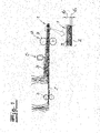
- a laminate 1 with at least two layers 2, 3 of spunbonded nonwoven fabric can be produced from endless filaments.
- the laminate is made only consists of two spunbonded layers 2 and 3.
- the continuous filaments are expediently and in the exemplary embodiment made of thermoplastic material.
- non-crimping continuous filaments or low-crimping continuous filaments are deposited on the first spunbonded nonwoven layer 2 .
- these continuous filaments have a central or symmetrical configuration and preferably a core-sheath configuration or cross-sectional configuration.
- the core is expediently and in the exemplary embodiment made of polypropylene and the jacket is made of polyethylene, with the weight ratio of polypropylene to polyethylene being preferred and being 70:30 in the exemplary embodiment.
- the higher proportion of propylene in the core contributes here to the stability or strength of the first spunbonded nonwoven layer 2 .
- the first lower spunbonded nonwoven layer 2 is then compacted or pre-solidified with the aid of a hot roller 4 .
- This first hot roller 4 may have a temperature of 120° C. in the exemplary embodiment.
- crimping continuous filaments or, compared to the continuous filaments of the first lower spunbonded nonwoven layer 2 , more strongly crimping continuous filaments are deposited over the first spunbonded nonwoven layer 2 to form the second upper spunbonded nonwoven layer 3 .
- These continuous filaments for the second upper spunbonded nonwoven layer 3 are expediently filaments with natural or latent crimping.
- continuous filaments in the form of bi-component filaments with a side-side configuration are used in the exemplary embodiment.
- first side consists of polypropylene and the second component (second side) of polyethylene, the weight ratio of polypropylene to polyethylene being suitably 40:60 to 60:40.
- second upper spunbonded nonwoven layer 3 is compacted or pre-solidified with the aid of a hot air knife 5 .
- the aggregate of the first lower spunbonded nonwoven layer 2 and the second upper spunbonded nonwoven layer 3 is preferably and in the exemplary embodiment finally consolidated with the aid of a calender 6 .
- the upper calender roll 7 is preferred and heated in the embodiment.
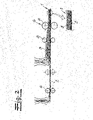
- bicomponent filaments with side-side configuration are also used for the second upper spunbonded nonwoven layer 3 .
- one component (first side) consists of a first polypropylene and the second component (second side) consists of a second polypropylene that is different or different from it.
- first side consists of a first polypropylene
- second side consists of a second polypropylene that is different or different from it.
- the second upper spunbonded nonwoven layer 3 is compacted or pre-solidified with the aid of a second hot roller 8 .
- the temperature of the first hot roller 4 for compacting or preconsolidating the first spunbonded nonwoven layer 2 is higher than the temperature of the second hot roller 8 for compacting or preconsolidating the second spunbonded nonwoven layer 3.
- the contact pressure of the first hot roller 4 is also recommended and in the exemplary embodiment higher as the contact pressure of the second hot roller 8.
- In the embodiment according to 2 becomes the aggregate following the compaction or pre-consolidation with the second hot roller 8 from the first lower spunbonded nonwoven layer 2 and the second upper spunbonded nonwoven layer 3 in turn finally consolidated with the aid of a calender 6 .
- the upper calender roll 7 of the calender 6 is expediently designed to be heated.
- the linear density of the continuous filaments of the first lower spunbonded nonwoven layer 2 is lower than the linear density of the continuous filaments of the second upper spunbonded nonwoven layer 3.
- the spunbonded nonwoven layers 2, 3 are produced or deposited with the proviso that the continuous filaments of the first lower Spunbonded nonwoven layer 2 is oriented more strongly in the machine direction (MD) than the continuous filaments of the second upper spunbonded nonwoven layer 3.
- the lower, more compact spunbonded nonwoven layer 2 is preferred and, in the exemplary embodiment, is stiffer or more tensile in the machine direction than the second upper spunbonded nonwoven layer 3.
- the first lower spunbonded nonwoven layer 2 expediently and in the exemplary embodiment, the strength or tensile strength and rigidity of the entire laminate 1.
- the second upper spunbonded nonwoven layer 3 ensures the softness and bulkiness of the laminate 1, so to speak.
Landscapes
- Engineering & Computer Science (AREA)
- Textile Engineering (AREA)
- Chemical & Material Sciences (AREA)
- Composite Materials (AREA)
- Mechanical Engineering (AREA)
- Physics & Mathematics (AREA)
- Thermal Sciences (AREA)
- Nonwoven Fabrics (AREA)
- Laminated Bodies (AREA)
- Multicomponent Fibers (AREA)
- Casting Or Compression Moulding Of Plastics Or The Like (AREA)
- Lining Or Joining Of Plastics Or The Like (AREA)
Description
Die Erfindung betrifft ein Verfahren zur Herstellung eines Laminates mit zumindest zwei Spinnvlieslagen aus Endlosfilamenten, insbesondere Endlosfilamenten aus thermoplastischem Kunststoff. Gegenstand der Erfindung ist weiterhin ein Laminat mit zumindest zwei Spinnvlieslagen aus Endlosfilamenten. - Endlosfilamente unterscheiden sich bekanntlich aufgrund ihrer quasi endlosen Länge von Stapelfasern, die viel geringere Längen von beispielsweise 10 mm bis 60 mm aufweisen. Es liegt im Rahmen der Erfindung, dass die Endlosfilamente für die Spinnvlieslagen des erfindungsgemäßen Laminates mit zumindest einer Spinneinrichtung bzw. mit zumindest einer Spinnerette erzeugt werden.The invention relates to a method for producing a laminate with at least two layers of spunbonded nonwoven fabric made of continuous filaments, in particular continuous filaments made of thermoplastic material. The subject matter of the invention is also a laminate with at least two layers of spunbonded nonwoven fabric made from continuous filaments. - Continuous filaments are known to differ from staple fibers, which have much shorter lengths of, for example, 10 mm to 60 mm, due to their quasi-endless length. It is within the scope of the invention that the endless filaments for the spunbonded layers of the laminate according to the invention are produced with at least one spinning device or with at least one spinnerette.
Verfahren zur Herstellung von Laminaten aus Spinnvliesen sind aus der Praxis und aus dem Stand der Technik in verschiedenen Ausführungsformen bekannt. Vor allem für Hygieneanwendungen sind Spinnvlieslaminate bzw. Spinnvliese mit ausreichender Weichheit erwünscht. Dabei ist es bekannt, die Weichheit eines Spinnvlieses durch den Einsatz von latent kräuselnden Endlosfilamenten zu erhöhen.Processes for producing laminates from spunbonded nonwovens are known from practice and from the prior art in various embodiments. Spunbonded nonwoven laminates or spunbonded nonwovens with sufficient softness are particularly desirable for hygiene applications. It is known that the softness of a spunbonded nonwoven can be increased by using latently crimping continuous filaments.
Die
Fernerhin ist es bekannt, Bikomponentenfilamente mit azentrischer Kern-Mantel-Konfiguration als latent kräuselnde Endlosfilamente zu verwenden. Die Weichheit der Spinnvliese kann durch Einsatz von weichen Rohstoffen erhöht werden. Dabei liegt jedoch ein Zielkonflikt vor, weil sehr weiche Spinnvliese gleichzeitig auch mechanisch weich bzw. mechanisch wenig stabil sind und höheren Kräften bzw. Zugkräften nicht ausreichend widerstehen können. Wenn die Spinnvliese zur Erhöhung ihrer Festigkeit beispielsweise mit Kalandern thermisch verfestigt werden, geht dies zu Lasten der Weichheit und Voluminösität der Spinnvliese und es resultiert ein eher flaches aber mechanisch stabiles Spinnvlies. Insoweit konkurrieren bei derartigen Herstellungsmethoden die mechanische Festigkeit bzw. Zugfestigkeit und Dimensionsstabilität des Vlieses mit der Weichheit bzw. Voluminösität des Spinnvlieses. Bei den bekannten Verfahren wird hier in der Regel kein zufriedenstellender Kompromiss erreicht.Furthermore, it is known to use bicomponent filaments with an acentric core-sheath configuration as latently crimping endless filaments. The softness of the spunbonded nonwovens can be increased by using soft raw materials. However, there is a conflict of objectives because the spunbonded nonwovens are very soft at the same time are also mechanically soft or mechanically not very stable and cannot withstand higher forces or tensile forces sufficiently. If the spunbonded nonwovens are thermally consolidated, for example with calenders, to increase their strength, this is at the expense of the softness and bulkiness of the spunbonded nonwovens and the result is a rather flat but mechanically stable spunbonded nonwoven. In this respect, with production methods of this type, the mechanical strength or tensile strength and dimensional stability of the nonwoven compete with the softness or bulkiness of the spunbonded nonwoven. In the case of the known methods, a satisfactory compromise is generally not achieved here.
Dementsprechend liegt der Erfindung das technische Problem zugrunde, ein Verfahren der eingangs genannten Art anzugeben, mit dem die Herstellung eines Laminates aus Spinnvlieslagen möglich ist, wobei sich das Laminat einerseits durch eine hohe Weichheit und Voluminösität und andererseits durch eine ausreichende Steifigkeit und Festigkeit bzw. Zugfestigkeit auszeichnet. Der Erfindung liegt weiterhin das technische Problem zugrunde, ein entsprechendes Laminat aus Spinnvlieslagen anzugeben.Accordingly, the invention is based on the technical problem of specifying a method of the type mentioned at the beginning, with which the production of a laminate from spunbonded layers is possible, the laminate being characterized on the one hand by a high level of softness and bulkiness and on the other hand by sufficient rigidity and strength or tensile strength excellent. The invention is also based on the technical problem of specifying a corresponding laminate of spunbonded nonwoven layers.
Zur Lösung des technischen Problems lehrt die Erfindung ein Verfahren zur Herstellung eines Laminates gemäß Patentanspruch 1. Erfindungsgemäß beträgt die Gesamtdicke d des Laminates weniger als 1,5 mm, bevorzugt weniger als 1 mm. Eine besonders bevorzugte Ausführungsform der Erfindung ist dadurch gekennzeichnet, dass die Gesamtdicke d des Laminates 0,2 mm bis 1 mm, empfohlenermaßen 0,3 mm bis 0,8 mm beträgt. - Die Gesamtdicke d des Laminates wird dabei nach DIN EN ISO 9073-2 (Februar 1997) gemessen und zwar nach der Messmethode 5.1 für normale Vliesstoffe. Dabei wird eine runde Auflagefläche von 2500 mm2 mit einem Druck von 0,5 kPa stoßfrei gegen die auf einer Bezugsplatte aufliegende Laminatprobe gedrückt. 10 Sekunden nach dem erstmaligen Kontakt der Auflagefläche mit dem Laminat wird der Abstand der beiden Platten als Gesamtdicke d des Laminates gemessen.To solve the technical problem, the invention teaches a method for producing a laminate according to patent claim 1. According to the invention, the total thickness d of the laminate is less than 1.5 mm, preferably less than 1 mm. A particularly preferred embodiment of the invention is characterized in that the total thickness d of the laminate is 0.2 mm to 1 mm, recommended 0.3 mm to 0.8 mm. - The total thickness d of the laminate is measured according to DIN EN ISO 9073-2 (February 1997), specifically according to measurement method 5.1 for normal non-woven fabrics. A round bearing surface of 2500 mm 2 is bumplessly against with a pressure of 0.5 kPa pressed the laminate sample lying on a reference plate. 10 seconds after the first contact of the support surface with the laminate, the distance between the two plates is measured as the total thickness d of the laminate.
Untere Spinnvlieslage meint im Rahmen der Erfindung eine zuerst bzw. früher abgelegte Spinnvlieslage aus Endlosfilamenten und obere Spinnvlieslage meint dagegen eine danach bzw. später auf der unteren Spinnvlieslage abgelegte Spinnvlieslage aus Endlosfilamenten. - Es liegt im Rahmen der Erfindung, dass die zumindest eine erste untere Spinnvlieslage und die zumindest eine zweite obere Spinnvlieslage nach dem Spunbond-Verfahren bzw. als Spunbond-Lagen erzeugt werden. Dazu werden die Endlosfilamente jeweils zunächst aus einem Spinnkopf bzw. aus einer Spinnerette ersponnen. Die ersponnenen Endlosfilamente werden zweckmäßigerweise danach in einer Kühlkammer abgekühlt und in einer Verstreckeinrichtung verstreckt. Die Abkühlung und Verstreckung erfolgt dabei insbesondere in einer kombinierten Abkühl- und Verstreckeinheit. Es empfiehlt sich, dass die Verstreckung der Endlosfilamente als aerodynamische Verstreckung erfolgt. Es liegt im Rahmen der Erfindung, dass das Aggregat aus der Kühlkammer und der Verstreckeinrichtung bzw. die kombinierte Abkühl- und Verstreckeinheit - abgesehen von der Luftzufuhr in der Kühlkammer bzw. Kühleinheit - als geschlossenes System ausgebildet ist. Das bedeutet, dass in diesem Aggregat außer der genannten Luftzufuhr in der Kühlkammer bzw. Kühleinheit keine weitere Luftzufuhr stattfindet. Diese Ausführungsform des geschlossenen Systems hat sich für die Herstellung eines erfindungsgemäßen Laminates besonders bewährt. - Nach einer bevorzugten Ausführungsform der Erfindung werden die abgekühlten und verstreckten Endlosfilamente für die beiden Spinnvlieslagen durch zumindest einen Diffusor geführt und im Anschluss daran auf einer Ablage, insbesondere auf einem Ablagesiebband abgelegt. Zweckmäßigerweise werden zunächst die Endlosfilamente für die erste untere Spinnvlieslage und anschließend die Endlosfilamente für die zweite obere Spinnvlieslage auf der Ablage bzw. auf dem Ablagesiebband abgelegt. Grundsätzlich könnten auch zuerst die Endlosfilamente für die zweite obere Spinnvlieslage auf der Ablage bzw. auf dem Ablagesiebband abgelegt werden und danach die Endlosfilmente der ersten unteren Spinnvliesbahn auf der Ablage bzw. auf dem Ablagesiebband abgelegt werden. - Es liegt im Übrigen im Rahmen der Erfindung, dass zwischen den Spinnvlieslagen (bzw. Spunbond-Lagen) zumindest eine Meltblown-Lage aus Meltblown-Fasern angeordnet wird. Es liegt weiterhin im Rahmen der Erfindung, dass die zumindest eine Meltblown-Lage nicht-kräuselnde Meltblown-Fasern aufweist.In the context of the invention, the lower spunbonded nonwoven layer means a spunbonded nonwoven layer made of continuous filaments laid down first or earlier, and the upper spunbonded nonwoven layer, on the other hand, means a spunbonded nonwoven layer made of continuous filaments laid down afterwards or later on the lower spunbonded nonwoven layer. It is within the scope of the invention that the at least one first lower spunbonded nonwoven layer and the at least one second upper spunbonded nonwoven layer are produced by the spunbond process or as spunbond layers. For this purpose, the continuous filaments are each first spun from a spinning head or from a spinneret. The spun continuous filaments are expediently then cooled in a cooling chamber and stretched in a stretching device. The cooling and stretching takes place in particular in a combined cooling and stretching unit. It is recommended that the continuous filaments be stretched as aerodynamic stretching. It is within the scope of the invention that the unit consisting of the cooling chamber and the stretching device or the combined cooling and stretching unit—apart from the air supply in the cooling chamber or cooling unit—is designed as a closed system. This means that in this unit there is no further air supply apart from the air supply mentioned in the cooling chamber or cooling unit. This embodiment of the closed system has proven particularly useful for the production of a laminate according to the invention. - According to a preferred embodiment of the invention, the cooled and stretched continuous filaments for the two spunbonded layers are guided through at least one diffuser and then deposited on a tray, in particular on a tray sieve belt. Expediently, the endless filaments are first for the first lower spunbonded nonwoven layer and then the continuous filaments for the second upper spunbonded nonwoven layer are deposited on the tray or on the tray sieve belt. In principle, the endless filaments for the second upper spunbonded nonwoven layer could first be deposited on the deposit or on the depositing sieve belt and then the endless filaments of the first lower spunbonded nonwoven web could be deposited on the deposit or on the depositing sieve belt. It is also within the scope of the invention that at least one meltblown layer made of meltblown fibers is arranged between the spunbonded layers (or spunbond layers). It is also within the scope of the invention that the at least one meltblown layer has non-crimping meltblown fibers.
Erfindungsgemäß wird die zumindest eine erste untere Spinnvlieslage mit zumindest einer Heißwalze kompaktiert bzw. vorverfestigt. Dadurch erfolgt also eine Kompaktierung bzw. eine gewisse Verfestigung der ersten unteren Spinnvlieslage. Dabei ist beabsichtigt, die erste untere Spinnvlieslage im Vergleich zur oberen Spinnvlieslage als relativ kompakte, steife und zugfeste Lage auszubilden. Die erste untere Spinnvlieslage soll zweckmäßigerweise die Stabilität des gesamten Laminates vornehmlich bestimmen. Nach einer Ausführungsform der Erfindung ist die Dicke der zumindest einen unteren Spinnvlieslage geringer als die Dicke der darüber angeordneten, zumindest einen zweiten oberen Spinnvlieslage. Es liegt im Rahmen der Erfindung, dass die Dichte der zumindest einen unteren Spinnvlieslage höher bzw. deutlich höher ist als die Dichte der darüber angeordneten, zumindest einen zweiten oberen Spinnvlieslage. Um eine ausreichende Gesamtstabilität bzw. um einen ausreichenden Zusammenhalt des Laminates zu erzielen, werden die zumindest zwei Spinnvlieslagen verfestigt. Dabei können eine Vorverfestigung und eine Endverfestigung stattfinden oder es kann auch lediglich eine Endverfestigung des Lagenaggregates stattfinden.According to the invention, the at least one first lower spunbonded nonwoven layer is compacted or pre-consolidated with at least one hot roller. This results in a compaction or a certain strengthening of the first lower spunbonded nonwoven layer. The intention here is to form the first lower spunbonded nonwoven layer as a relatively compact, stiff and tensile layer in comparison to the upper spunbonded nonwoven layer. The first lower layer of spun-bonded non-woven material should expediently primarily determine the stability of the entire laminate. According to one embodiment of the invention, the thickness of the at least one lower spunbonded nonwoven layer is less than the thickness of the at least one second upper spunbonded nonwoven layer arranged above it. It is within the scope of the invention that the density of the at least one lower spunbonded nonwoven layer is higher or significantly higher than the density of the at least one second upper spunbonded nonwoven layer arranged above it. In order to achieve sufficient overall stability or to achieve sufficient cohesion of the laminate, the at least two layers of spunbonded nonwoven are bonded. A pre-consolidation and a final consolidation can take place, or only a final consolidation of the layer aggregate can take place.
Das nach dem erfindungsgemäßen Verfahren hergestellte Laminat zeichnet sich zunächst durch eine zufriedenstellende Stabilität bzw. Dimensionsstabilität, insbesondere in Maschinenrichtung aus. Das Laminat ist insgesamt ausreichend kompakt und weist eine ausreichende Steifigkeit auf. Zugleich zeichnet sich das Laminat durch eine verhältnismäßig hohe Weichheit und Voluminösität aus. Dabei wird die Stabilität und Steifigkeit in erster Linie durch die erste untere Spinnvlieslage gewährleistet und die Weichheit bzw. Voluminösität durch die zweite obere Spinnvlieslage. Das Laminat weist weiterhin einen guten Griff und eine vergleichsweise niedrige Dichte auf.The laminate produced by the process according to the invention is initially distinguished by satisfactory stability or dimensional stability, particularly in the machine direction. The laminate is sufficiently compact overall and has sufficient rigidity. At the same time, the laminate is characterized by a relatively high degree of softness and volume. The stability and rigidity are primarily ensured by the first lower spunbonded nonwoven layer and the softness or volume by the second upper spunbonded nonwoven layer. The laminate also has a good hand and a comparatively low density.
Erfindungsgemäß werden für die erste untere Spinnvlieslage Mehrkomponentenfilamente bzw. Bikomponentenfilamente mit symmetrischer bzw. zentrischer Konfiguration (Querschnittskonfiguration) eingesetzt. Besonders bevorzugt werden dabei Mehrkomponentenfilamente bzw. Bikomponentenfilamente mit zentrischer bzw. symmetrischer Kern-Mantel-Konfiguration verwendet. Grundsätzlich können aber auch andere symmetrische Querschnittskonfigurationen eingesetzt werden, beispielsweise trilobale Konfigurationen und dergleichen. Zweckmäßigerweise bestehen zumindest 85 Gew.-%, vorzugsweise zumindest 90 Gew.-%, bevorzugt zumindest 95 Gew.-% und sehr bevorzugt zumindest 98 Gew.-% der Endlosfilamente der ersten unteren Spinnvlieslage aus Monokomponentenfilamenten und/oder aus den beschriebenen Mehrkomponentenfilamenten bzw. Bikomponentenfilamenten mit symmetrischer Querschnittskonfiguration.According to the invention, multicomponent filaments or bicomponent filaments with a symmetrical or central configuration (cross-sectional configuration) are used for the first lower spunbonded nonwoven layer. Multi-component filaments or bi-component filaments with a central or symmetrical core-sheath configuration are particularly preferably used. In principle, however, other symmetrical cross-sectional configurations can also be used, for example trilobal configurations and the like. Appropriately, at least 85% by weight, preferably at least 90% by weight, preferably at least 95% by weight and very preferably at least 98% by weight of the continuous filaments of the first lower spunbonded nonwoven layer consist of monocomponent filaments and/or of the described multicomponent filaments or bicomponent filaments with symmetrical cross-sectional configuration.
Es empfiehlt sich, dass die Endlosfilamente der ersten unteren Spinnvlieslage aus zumindest einem Polyolefin bzw. im Wesentlichen aus zumindest einem Polyolefin bestehen. Vorzugsweise bestehen die Endlosfilamente der ersten unteren Spinnvlieslage aus Polypropylen und/oder aus Polyethylen bzw. im Wesentlichen aus Polypropylen und/oder Polyethylen. Bei Verwendung von Bikomponentenfilamenten bzw. Mehrkomponentenfilamenten für die Endlosfilamente der ersten unteren Spinnvlieslage besteht zumindest eine Komponente dieser Endlosfilamente aus zumindest einem Polyolefin, vorzugsweise aus Polypropylen und/oder Polyethylen. Eine bevorzugte Ausführungsform des erfindungsgemäßen Verfahrens ist dadurch gekennzeichnet, dass für die erste untere Spinnvlieslage Endlosfilamente bzw. Mehrkomponentenfilamente/Bikomponentenfilamente mit zentrischer Kern-Mantel-Konfiguration verwendet werden. Dabei besteht der Kern zweckmäßigerweise aus Polypropylen und der Mantel bevorzugt aus Polyethylen. Das Gewichtsverhältnis Kern zu Mantel bzw. Polypropylen zu Polyethylen beträgt dabei empfohlenermaßen 50:50 bis 80:20, bevorzugt 70:30. Der Erfindung liegt im Übrigen die Erkenntnis zugrunde, dass ein höherer Polypropylen-Anteil im Kern für die Stabilität des erfindungsgemäßen Laminates sehr hilfreich bzw. wesentlich ist.It is recommended that the endless filaments of the first lower spunbonded nonwoven layer consist of at least one polyolefin or essentially of at least one polyolefin. Preferably, the continuous filaments consist of the first lower spunbonded nonwoven layer made of polypropylene and/or polyethylene or essentially made of polypropylene and/or polyethylene. When bi-component filaments or multi-component filaments are used for the continuous filaments of the first lower spunbonded nonwoven layer, at least one component of these continuous filaments consists of at least one polyolefin, preferably polypropylene and/or polyethylene. A preferred embodiment of the method according to the invention is characterized in that continuous filaments or multi-component filaments/bi-component filaments with a central core-sheath configuration are used for the first lower spunbonded nonwoven layer. The core is expediently made of polypropylene and the jacket is preferably made of polyethylene. The recommended weight ratio of core to sheath or polypropylene to polyethylene is 50:50 to 80:20, preferably 70:30. The invention is also based on the knowledge that a higher proportion of polypropylene in the core is very helpful or essential for the stability of the laminate according to the invention.
Eine besonders empfohlene Ausführungsform der Erfindung ist dadurch gekennzeichnet, dass als Endlosfilamente für die zweite obere Spinnvlieslage Endlosfilamente mit natürlicher Kräuselung bzw. mit latenter Kräuselneigung eingesetzt werden. Zweckmäßigerweise besteht die zweite obere Spinnvlieslage zu mindestens 85 Gew.-%, vorzugsweise zu mindestens 90 Gew.-%, bevorzugt zu mindestens 95 Gew.-% und sehr bevorzugt zu mindestens 98 Gew.-% aus Endlosfilamenten mit natürlicher Kräuselung bzw. mit latenter Kräuselung. - Es liegt im Rahmen der Erfindung, dass in diesen Endlosfilamenten durch Wahl der Rohstoffe und der Prozesseinstellungen eine inhärente Kräuselneigung hervorgerufen wird.A particularly recommended embodiment of the invention is characterized in that continuous filaments with natural crimping or with a latent tendency to crimp are used as continuous filaments for the second upper spunbonded nonwoven layer. Expediently, the second upper spunbonded nonwoven layer consists of at least 85% by weight, preferably at least 90% by weight, preferably at least 95% by weight and very preferably at least 98% by weight of continuous filaments with natural crimps or latent crimps ripple. - It is within the scope of the invention that an inherent tendency to crimp is caused in these endless filaments by the choice of raw materials and process settings.
Nach besonders bevorzugter Ausführungsform der Erfindung werden als Endlosfilamente für die zweite obere Spinnvlieslage Mehrkomponentenfilamente bzw. Bikomponentenfilamente mit Seite-Seite-Konfiguration (side-by-side-Konfiguration) eingesetzt. Gemäß einer weiteren Ausführungsform werden Mehrkomponentenfilamente bzw. Bikomponentenfilamente mit azentrischer bzw. unsymmetrischer Querschnittskonfiguration eingesetzt, insbesondere mit azentrischer bzw. unsymmetrischer Kern-Mantel-Konfiguration. Vorzugsweise bestehen die Endlosfilamente für die zweite obere Spinnvlieslage zu mindestens 85 Gew.-%, zweckmäßigerweise zu mindestens 90 Gew.-%, bevorzugt zu mindestens 95 Gew.-% und sehr bevorzugt zu mindestens 98 Gew.-% aus derartigen Filamenten bzw. Mehrkomponentenfilamenten mit Seite-Seite-Konfiguration und/oder azentrischer Querschnittskonfiguration.According to a particularly preferred embodiment of the invention, multi-component filaments or bi-component filaments with a side-side configuration (side-by-side configuration) are used as endless filaments for the second upper spunbonded nonwoven layer. According to a further embodiment, multi-component filaments or bi-component filaments with an acentric or asymmetrical cross-sectional configuration are used, in particular with an acentric or asymmetrical core-sheath configuration. The continuous filaments for the second upper spunbonded nonwoven layer preferably consist of at least 85% by weight, expediently at least 90% by weight, preferably at least 95% by weight and very preferably at least 98% by weight of such filaments or multi-component filaments with side-side configuration and/or acentric cross-sectional configuration.
Eine bevorzugte Ausführungsform der Erfindung ist dadurch gekennzeichnet, dass zumindest eine Komponente der Mehrkomponentenfilamente bzw. Bikomponentenfilamente für die zweite Spinnvlieslage aus zumindest einem Polyolefin bzw. im Wesentlichen aus zumindest einem Polyolefin besteht. Zweckmäßigerweise bestehen alle Komponenten der Mehrkomponentenfilamente bzw. Bikomponentenfilamente aus zumindest einem Polyolefin bzw. im Wesentlichen aus zumindest einem Polyolefin. Grundsätzlich sind aber auch andere Rohstoffe, insbesondere Polyamid oder Polyethylenterephthalat für die Komponenten möglich. - Bei den Polyolefinen handelt es sich insbesondere um Polypropylen und/oder Polyethylen. Gemäß einer Ausführungsform der Erfindung sind Bikomponentenfilamente in Seite-Seite-Konfiguration für die zweite obere Spinnvlieslage vorgesehen und dabei besteht eine Komponente aus Polypropylen und die andere Komponente aus Polyethylen, wobei das Verhältnis Polypropylen zu Polyethylen 40:60 bis 60:40 beträgt.A preferred embodiment of the invention is characterized in that at least one component of the multicomponent filaments or bicomponent filaments for the second spunbonded nonwoven layer consists of at least one polyolefin or essentially of at least one polyolefin. Expediently, all components of the multi-component filaments or bi-component filaments consist of at least one polyolefin or essentially of at least one polyolefin. In principle, however, other raw materials, in particular polyamide or polyethylene terephthalate, are also possible for the components. - The polyolefins are in particular polypropylene and/or polyethylene. According to one embodiment of the invention, bicomponent filaments are provided in a side-to-side configuration for the second top spunbonded nonwoven layer and one component is polypropylene and the other component is polyethylene, with a polypropylene to polyethylene ratio of 40:60 to 60:40.
Nach einer anderen bevorzugten Ausführungsform der Erfindung werden als Endlosfilamente mit latenter Kräuselneigung für die zweite obere Spinnvlieslage Mehrkomponentenfilamente bzw. Bikomponentenfilamente aus zumindest zwei unterschiedlichen Polypropylenen eingesetzt. Unterschiedliche Polypropylene meint hier und nachfolgend insbesondere Polypropylene mit unterschiedlicher Molmassenverteilung und/oder unterschiedlicher Viskosität und/oder unterschiedlicher Isotaktizität. Als Polypropylene werden bevorzugt Polypropylen-Homopolymere und/oder Polypropylene-Copolymere verwendet. - Gemäß einer empfohlenen Ausführungsform der Erfindung werden für die Endlosfilamente der zweiten Spinnvlieslage Bikomponentenfilamente in Seite-Seite-Konfiguration eingesetzt und dabei bestehen die beiden Komponenten der Bikomponentenfilamente aus unterschiedlichen Polypropylenen. Nach einer weiteren bevorzugten Ausführungsform der Erfindung werden für die Endlosfilamente der zweiten oberen Spinnvlieslage Mehrkomponentenfilamente bzw. Bikomponentenfilamente mit unsymmetrischer Querschnittskonfiguration verwendet und diese Mehrkomponentenfilamente bzw. Bikomponentenfilamente weisen für die einzelnen Komponenten unterschiedliche Polypropylene auf.According to another preferred embodiment of the invention, multicomponent filaments or bicomponent filaments made of at least two different polypropylenes are used as continuous filaments with a latent tendency to curl for the second upper spunbonded nonwoven layer. Here and below, different polypropylenes means in particular polypropylenes with different molar mass distribution and/or different viscosity and/or different isotacticity. Polypropylene homopolymers and/or polypropylene copolymers are preferably used as polypropylene. - According to a recommended embodiment of the invention, bicomponent filaments are used in side-to-side configuration for the endless filaments of the second spunbonded nonwoven layer, and the two components of the bicomponent filaments consist of different polypropylenes. According to a further preferred embodiment of the invention, multicomponent filaments or bicomponent filaments with an asymmetrical cross-section configuration are used for the continuous filaments of the second upper spunbonded nonwoven layer, and these multicomponent filaments or bicomponent filaments have different polypropylenes for the individual components.
Eine Ausführungsform der Erfindung ist dadurch gekennzeichnet, dass die zweite obere Spinnvlieslage mit Hilfe von Heißluft kompaktiert bzw. vorverfestigt wird. Dazu kann insbesondere zumindest ein Heißluftmesser eingesetzt werden, das die zweite obere Spinnvlieslage bevorzugt von oben her beaufschlagt.An embodiment of the invention is characterized in that the second upper spunbonded nonwoven layer is compacted or pre-solidified with the aid of hot air. In particular, at least one hot air knife can be used for this purpose, which preferably acts on the second upper spunbonded nonwoven layer from above.
Erfindungsgemäß wird die zweite obere Spinnvlieslage mittels zumindest einer Heißwalze (heiße Auslaufwalze) kompaktiert bzw. vorverfestigt, wobei die Temperatur der ersten Heißwalze zur Kompaktierung bzw. Vorverfestigung der ersten unteren Spinnvlieslage höher ist als die Temperatur der zweiten Heißwalze zur Kompaktierung bzw. Vorverfestigung der zweiten oberen Spinnvlieslage.According to the invention, the second upper spunbonded nonwoven layer is compacted or pre-consolidated by means of at least one hot roller (hot outlet roller), the temperature of the first hot roller for compacting or pre-consolidating the first lower spunbonded nonwoven layer being higher than the temperature of the second Hot roller for compaction or pre-consolidation of the second upper spunbonded nonwoven layer.
Erfindungsgemäß ist zusätzlich zu dem vorstehend erläuterten Temperaturunterschied auch der Anpressdruck der ersten Heißwalze zur Kompaktierung bzw. Vorverfestigung der ersten unteren Spinnvlieslage höher als der Anpressdruck der zweiten Heißwalze zur Kompaktierung bzw. Vorverfestigung der zweiten oberen Spinnvlieslage. - Eine Ausführungsform des erfindungsgemäßen Verfahrens ist dadurch gekennzeichnet, dass die Temperatur der ersten Heißwalze zur Kompaktierung bzw. Vorverfestigung der ersten unteren Spinnvlieslage 100 bis 130 °C beträgt und dass die Temperatur der zweiten Heißwalze zur Kompaktierung bzw. Vorverfestigung der zweiten oberen Spinnvlieslage 70 bis 100 °C beträgt. Es liegt dabei im Rahmen der Erfindung, dass die Temperaturen mit erhöhter Anlagengeschwindigkeit ansteigen.According to the invention, in addition to the temperature difference explained above, the contact pressure of the first hot roller for compacting or preconsolidating the first lower spunbonded nonwoven layer is higher than the contact pressure of the second hot roller for compacting or preconsolidating the second upper spunbonded nonwoven layer. - An embodiment of the method according to the invention is characterized in that the temperature of the first hot roller for compacting or pre-consolidation of the first lower spunbonded non-woven layer is 100 to 130 ° C and that the temperature of the second hot roller for compacting or pre-consolidation of the second upper spun-bonded nonwoven layer is 70 to 100 °C. It is within the scope of the invention that the temperatures rise with increased system speed.
Fernerhin liegt es im Rahmen der Erfindung, dass das Aggregat aus der ersten unteren Spinnvlieslage und der zweiten oberen Spinnvlieslage bzw. das Lagenaggregat für das Laminat endverfestigt wird, vorzugsweise mittels zumindest eines Kalanders endverfestigt wird. Grundsätzlich kann auch eine Heißluft-Endverfestigung des Laminates erfolgen. Nach einer Ausführungsvariante des erfindungsgemäßen Verfahrens ist ein niedrig schmelzender thermoplastischer Kunststoff - insbesondere niedrig schmelzendes Polyethylen - als Komponente in beiden Spinnvlieslagen vorhanden. Auf diese Weise lässt sich eine sehr effektive Endverfestigung des Laminates erzielen.Furthermore, it is within the scope of the invention that the aggregate of the first lower spunbonded nonwoven layer and the second upper spunbonded nonwoven layer or the layer aggregate for the laminate is finally consolidated, preferably by means of at least one calender. In principle, final consolidation of the laminate with hot air can also take place. According to one embodiment of the method according to the invention, a low-melting thermoplastic material—in particular low-melting polyethylene—is present as a component in both spunbonded nonwoven layers. In this way, a very effective final consolidation of the laminate can be achieved.
Es empfiehlt sich, dass das erfindungsgemäße Verfahren bzw. die Kompaktierung(en) und/oder die Vorverfestigung(en) und/oder Verfestigung(en) im Rahmen des erfindungsgemäßen Verfahrens mit der Maßgabe durchgeführt wird/werden, dass die Dicke d1 der ersten unteren Spinnvlieslage im Laminat 0,1 bis 0,3 mm und sehr bevorzugt 0,15 bis 0,2 mm beträgt und/oder das die Dicke d2 der zweiten oberen Spinnvlieslage im Laminat 0,2 bis 0,95 mm beträgt. - Die einzelnen Dicken d1 und d2 der Spinnvlieslagen im Laminat werden dabei nach bevorzugter Ausführungsform wie nachfolgend beschrieben gemessen. Zunächst wird wie weiter oben erläutert die Gesamtdicke des Laminates nach DIN EN ISO 9073-2 (Februar 1997) gemessen. Anschließend wird das Laminat mittels zustellbaren Flächen auf die so gemessene Gesamtdicke des Laminates komprimiert. Das auf diese Weise erzeugte Vliesvolumen wird zweckmäßiger Weise mittels eines vorzugsweise transparenten Gießharzes aufgefüllt und man lässt das Harz dann aushärten. An dem auf diese Weise stabilisierten Laminat können dann die Dicken der einzelnen Lagen gemessen werden. Dazu können beispielsweise nach einem Schnitt quer zur Oberfläche des Laminates die einzelnen Dicken der Lagen optisch vermessen werden. Es kann auch in der Aufsicht des Laminates insbesondere mittels Raster-Mikroskopie eine Erfassung der einzelnen Grenzflächen und ihrer Höhen-Positionen im Laminat erfolgen.It is recommended that the method according to the invention or the compaction(s) and/or the preconsolidation(s) and/or consolidation(s) within the scope of the method according to the invention be carried out with the proviso will/are that the thickness d 1 of the first lower spunbonded nonwoven layer in the laminate is 0.1 to 0.3 mm and very preferably 0.15 to 0.2 mm and/or that the thickness d 2 of the second upper spunbonded nonwoven layer in the laminate is 0 .2 to 0.95mm. - The individual thicknesses d 1 and d 2 of the spunbonded layers in the laminate are measured according to the preferred embodiment as described below. First, as explained above, the total thickness of the laminate is measured according to DIN EN ISO 9073-2 (February 1997). The laminate is then compressed to the total thickness of the laminate measured in this way using adjustable surfaces. The fleece volume produced in this way is expediently filled with a preferably transparent casting resin and the resin is then allowed to harden. The thicknesses of the individual layers can then be measured on the laminate stabilized in this way. For this purpose, for example, after a cut across the surface of the laminate, the individual thicknesses of the layers can be measured optically. The individual boundary surfaces and their height positions in the laminate can also be detected in the plan view of the laminate, in particular by means of scanning microscopy.
Es ist erfindungsgemäß, dass die Spinnvlieslagen des erfindungsgemäßen Laminates mit der Maßgabe erzeugt bzw. abgelegt werden, dass die Endlosfilamente der ersten unteren Spinnvlieslage stärker in Maschinenrichtung (MD) orientiert sind als die Endlosfilamente der zweiten oberen Spinnvlieslage. Insoweit weist die erste untere Spinnvlieslage in Maschinenrichtung eine höhere Steifigkeit auf als die zweite obere Spinnvlieslage des Laminates. Bei der ersten unteren Spinnvlieslage handelt es sich im Vergleich zur zweiten oberen Spinnvlieslage um eine kompaktere, steifere und dichtere Spinnvlieslage. Die erste untere Spinnvlieslage bestimmt zweckmäßigerweise die Stabilität des Gesamtproduktes.According to the invention, the spunbonded nonwoven layers of the laminate according to the invention are produced or deposited with the proviso that the continuous filaments of the first lower spunbonded nonwoven layer are oriented more in the machine direction (MD) than the continuous filaments of the second upper spunbonded nonwoven layer. In this respect, the first lower spunbonded nonwoven layer has a higher rigidity in the machine direction than the second upper spunbonded nonwoven layer of the laminate. The first bottom spunbond layer is a more compact, stiffer and denser spunbond layer compared to the second top spunbond layer. The first lower spunbonded nonwoven layer expediently determines the stability of the overall product.
Eine sehr empfohlene Ausführungsform des erfindungsgemäßen Verfahrens ist dadurch gekennzeichnet, dass die Längssteifigkeit sL des fertigen Laminates aus der zumindest einen ersten Spinnvlieslage und aus der zumindest einen zweiten Spinnvlieslage 20 bis 80 %, bevorzugt 40 bis 65 % der Längssteifigkeit sV eines Vergleichsvlieses bzw. Vergleichslaminates beträgt. Dabei besteht das Vergleichsvlies bzw. das Vergleichslaminat aus dem gleichen Material wie die zumindest eine erste Spinnvlieslage des Laminates und das Vergleichsvlies bzw. das Vergleichslaminat hat das gleiche Flächengewicht wie das Laminat. Weiterhin wurde das Vergleichsvlies bzw. Vergleichslaminat mit der gleichen Vorrichtung hergestellt wie das Laminat sowie unter gleichen Bedingungen wie das Laminat. Es liegt dabei im Rahmen der Erfindung, dass das Vergleichsvlies bzw. das Vergleichslaminat die gleiche Anzahl von Lagen bzw. Spinnvlieslagen aufweist wie das Laminat und dass alle Lagen bzw. Spinnvlieslagen des Vergleichsvlieses bzw. Vergleichslaminates unter den gleich Bedingungen hergestellt werden wie die erste Spinnvlieslage des Laminates. Insbesondere erfolgt die Vorverfestigung bzw. Verfestigung in der gleichen Weise wie die Vorverfestigung bzw. Verfestigung der ersten Spinnvlieslage des Laminates. So erfolgt beispielsweise bei einer Vorverfestigung der ersten Spinnvlieslage des Laminates mittels eines Kalanders mit 5 bis 22 % Schweißfläche auch eine Vorverfestigung bzw. Verfestigung des Vergleichsvlieses / Vergleichslaminates mittels dieses Kalanders mit 5 bis 22 % Schweißfläche.A highly recommended embodiment of the method according to the invention is characterized in that the longitudinal stiffness s L of the finished laminate of the at least one first spunbonded nonwoven layer and the at least one second spunbonded nonwoven layer is 20 to 80%, preferably 40 to 65% of the longitudinal stiffness s V of a comparative nonwoven or Comparative laminates is. The comparison nonwoven or the comparison laminate consists of the same material as the at least one first spunbonded nonwoven layer of the laminate and the comparison nonwoven or the comparison laminate has the same weight per unit area as the laminate. Furthermore, the comparison fleece or comparison laminate was produced with the same device as the laminate and under the same conditions as the laminate. It is within the scope of the invention that the comparative nonwoven or the comparative laminate has the same number of layers or spunbonded nonwoven layers as the laminate and that all layers or spunbonded nonwoven layers of the comparative nonwoven or comparative laminate are produced under the same conditions as the first spunbonded nonwoven layer of the laminates. In particular, the preconsolidation or consolidation takes place in the same way as the preconsolidation or consolidation of the first spunbonded nonwoven layer of the laminate. For example, when the first spunbonded nonwoven layer of the laminate is preconsolidated using a calender with 5 to 22% weld area, the comparative nonwoven/comparative laminate is also preconsolidated or consolidated using this calender with 5 to 22% weld area.
Die Längssteifigkeit sL des (fertigen) Laminates und die Längssteifigkeit sV des Vergleichsvlieses bzw. Vergleichslaminates werden im Rahmen der Erfindung insbesondere als die Kraft bei 5 % Dehnung des Laminates bzw. des Vergleichsvlieses/Vergleichslaminates aus der Spannung-Dehnungskurve ermittelt, wobei die Längssteifigkeit vorzugsweise auf das Flächengewicht des Laminates oder des Vergleichsvlieses/Vergleichslaminates normiert wird, so dass die Einheit der Längssteifigkeit (N/5 cm)/(g/m2) ist. - Es liegt im Rahmen der Erfindung, dass die Messung der Längssteifigkeit bzw. der Spannungs-Dehnungskurve nach EDANA 20.2-89 erfolgt. Weiterhin liegt es im Rahmen der Erfindung, dass dabei eine Vliesprobe bzw. Laminatprobe mit einer Breite von 50 mm zwischen zwei Klemmeinrichtungen mit einem Abstand von 100 mm eingespannt wird, so dass die untersuchte/gemessene Länge der Probe 100 mm beträgt. Anschließend wird diese Vliesprobe bzw. Laminatprobe mittels einer Zugmaschine bei einem Vorschub von 100 mm/min bis zu einer Vorkraft von 0,5 N gespannt. In diesem Zustand erfolgt dann das Zurücksetzen der Messung auf Null und die eigentliche Messung beginnt. Die Zugmaschine arbeitet dabei mit einem Vorschub bzw. mit einer Zuggeschwindigkeit von 200 mm/min. Wie oben bereits dargelegt wird also die Längssteifigkeit als Kraft bei 5 % Dehnung der Probe aus der Spannungs-Dehnungskurve ermittelt.The longitudinal stiffness s L of the (finished) laminate and the longitudinal stiffness s V of the comparison fleece or comparison laminate are determined in the context of the invention in particular as the force at 5% elongation of the laminate or the comparison fleece / comparison laminate from the stress-strain curve, with the longitudinal stiffness preferably on the basis weight of the Laminates or the comparison fleece/comparison laminate is normalized, so that the unit of the longitudinal stiffness is (N/5 cm)/(g/m 2 ). - It is within the scope of the invention that the measurement of the longitudinal stiffness or the stress-strain curve is carried out according to EDANA 20.2-89. Furthermore, it is within the scope of the invention that a fleece sample or laminate sample with a width of 50 mm is clamped between two clamping devices at a distance of 100 mm, so that the tested/measured length of the sample is 100 mm. This fleece sample or laminate sample is then stretched using a traction machine at a feed rate of 100 mm/min up to a preload of 0.5 N. In this state, the measurement is then reset to zero and the actual measurement begins. The traction machine works with a feed or with a traction speed of 200 mm/min. As already explained above, the longitudinal stiffness is determined as a force at 5% elongation of the sample from the stress-strain curve.
Nach einer Ausführungsform des erfindungsgemäßen Verfahrens kann die Herstellung der zumindest zwei Spinnvlieslagen im inline-Verfahren erfolgen. Gemäß einer anderen Ausführungsvariante ist auch eine offline-Herstellung der Spinnvlieslagen möglich. So kann beispielsweise zunächst nur die zumindest eine erste untere Spinnvlieslage hergestellt werden und zu einem anderen Zeitpunkt und/oder zu einem anderen Ort wird dann die zumindest eine obere Spinnvlieslage auf der zumindest einen ersten unteren Spinnvlieslage abgelegt. Das Laminat aus den zumindest zwei Spinnvlieslagen wird anschließend verfestigt. Von daher liegen im Rahmen des erfindungsgemäßen Verfahrens sowohl eine inline-Herstellung als auch eine offline-Herstellung des Laminates.According to one embodiment of the method according to the invention, the at least two spunbonded nonwoven layers can be produced in an inline method. According to another embodiment variant, offline production of the spunbonded nonwoven layers is also possible. For example, initially only the at least one first lower spunbonded nonwoven layer can be produced and then at a different time and/or at a different location the at least one upper spunbonded nonwoven layer is placed on the at least one first lower spunbonded nonwoven layer. The laminate of the at least two layers of spunbonded nonwoven is then consolidated. Therefore, both inline production and offline production of the laminate are within the scope of the method according to the invention.
Zur Lösung des technischen Problems lehrt die Erfindung weiterhin ein Laminat gemäß Patentanspruch 10.To solve the technical problem, the invention further teaches a laminate according to patent claim 10.
Es liegt im Rahmen der Erfindung, dass die Kräuselung der Spinnvlieslagen im Laminat von unten nach oben zunimmt. Insoweit liegt es auch im Rahmen der Erfindung, dass die Kräuselung der Spinnvlieslagen im Laminat von unten nach oben von nicht latent kräuselnd bis latent kräuselnd zunimmt. Fernerhin liegt es im Rahmen der Erfindung, dass die Dichte der Spinnvlieslagen im Laminat von unten nach oben abnimmt. Gemäß einer Ausführungsvariante der Erfindung nimmt die Dicke der Spinnvlieslagen im Laminat von unten nach oben zu. Grundsätzlich können die Dicken aber auch identisch bzw. ähnlich sein oder die Dicke der Spinnvlieslagen kann im Laminat auch von unten nach oben abnehmen. Nach sehr empfohlener Ausführungsform nimmt jedenfalls die Dichte der Spinnvlieslagen im Laminat von unten nach oben ab.It is within the scope of the invention that the crimping of the spunbonded layers in the laminate increases from bottom to top. In this respect, it is also within the scope of the invention for the crimping of the spunbonded nonwoven layers in the laminate to increase from bottom to top, from not latently crimping to latently crimping. Furthermore, it is within the scope of the invention that the density of the spunbonded layers in the laminate decreases from bottom to top. According to one embodiment of the invention, the thickness of the spunbonded layers in the laminate increases from bottom to top. In principle, however, the thicknesses can also be identical or similar, or the thickness of the spunbonded nonwoven layers can also decrease from bottom to top in the laminate. According to the highly recommended embodiment, the density of the spunbonded layers in the laminate decreases from bottom to top.
Erfindungsgemäß beträgt das Dickenverhältnis der Dicke d1 der ersten unteren Spinnvlieslage zur Dicke d2 der zweiten oberen Spinnvlieslage 1:2 bis 1:4. Somit ist nach einer Ausführungsform der Erfindung die Dicke d2 der zumindest einen zweiten oberen Spinnvlieslage zwei- bis viermal so groß wie die Dicke d1 der zumindest einen ersten unteren Spinnvlieslage.According to the invention, the thickness ratio of the thickness d 1 of the first lower spunbonded nonwoven layer to the thickness d 2 of the second upper spunbonded nonwoven layer is 1:2 to 1:4. Thus, according to one embodiment of the invention, the thickness d 2 of the at least one second upper spunbonded nonwoven layer is two to four times greater than the thickness d 1 of the at least one first lower spunbonded nonwoven layer.
Erfindungsgemäß weisen die Endlosfilamente der ersten unteren Spinnvlieslage einen Titer von 1,0 bis 2,5 den, bevorzugt von 1,2 bis 2 den auf. Erfindungsgemäß weisen die Endlosfilamente der zweiten oberen Spinnvlieslage einen Titer von 1,8 bis 2,5 den auf. Eine besonders empfohlene Ausführungsform ist dadurch gekennzeichnet, dass der Titer der zweiten oberen Spinnvlieslage kleiner ist als 2,2 den. Weiter erfindungsgemäß ist, dass der Filamentdurchmesser der Endlosfilamente der zumindest einen ersten unteren Spinnvlieslage geringer ist als der Filamentdurchmesser der Endlosfilamente der zumindest einen zweiten oberen Spinnvlieslage. Von daher nimmt der Titer der Spinnvlieslagen im Laminat von unten nach oben hin zu.According to the invention, the continuous filaments of the first lower spunbonded nonwoven layer have a linear density of 1.0 to 2.5 den, preferably 1.2 to 2 den. According to the invention, the continuous filaments of the second upper spunbonded nonwoven layer have a linear density of 1.8 to 2.5 deniers. A particularly recommended embodiment is characterized in that the linear density of the second upper spunbonded nonwoven layer is less than 2.2 den. It is further according to the invention that the filament diameter of the continuous filaments of the at least one first lower spunbonded nonwoven layer is less than the filament diameter of the Endless filaments of the at least one second upper spunbonded nonwoven layer. For this reason, the titre of the spunbonded layers in the laminate increases from bottom to top.
Der Erfindung liegt die Erkenntnis zugrunde, dass mit dem erfindungsgemäßen Verfahren auf einfache Weise ein Laminat herstellbar ist, das sich zum einen durch hohe Stabilität bzw. Dimensionsstabilität - insbesondere in Maschinenrichtung - auszeichnet und zum anderen durch verhältnismäßig hohe Weichheit bzw. Voluminösität. Insoweit wird ein optimaler Kompromiss zwischen Stabilität/Festigkeit zum einen und Weichheit/Voluminösität zum anderen erzielt. Der Erfindung liegt fernerhin die Erkenntnis zugrunde, dass die zumindest eine erste untere Spinnvlieslage die Steifigkeit - insbesondere in Maschinenrichtung des Laminates - in ausreichendem Maße sicherstellt. Das erfindungsgemäße Laminat ist ausreichend kompakt, weist einen guten Griff auf und zeichnet sich auch durch eine verhältnismäßig niedrige Gesamtdichte auf. Hervorzuheben ist weiterhin, dass das erfindungsgemäße Laminat durch relativ einfache und wenig aufwendige Weise herstellbar ist und sich insoweit auch durch verhältnismäßig geringe Kosten auszeichnet. Das erfindungsgemäße Laminat kann vor allem für Hygieneanwendungen, beispielsweise für Windeln und dergleichen eingesetzt werden. Grundsätzlich sind aber auch andere Anwendungsmöglichkeiten denkbar.The invention is based on the finding that the method according to the invention can be used to produce a laminate in a simple manner which is characterized on the one hand by high stability or dimensional stability—especially in the machine direction—and on the other hand by relatively high softness or bulkiness. In this respect, an optimal compromise is achieved between stability/strength on the one hand and softness/voluminousness on the other. Furthermore, the invention is based on the knowledge that the at least one first lower spunbonded nonwoven layer ensures the rigidity to a sufficient extent—in particular in the machine direction of the laminate. The laminate according to the invention is sufficiently compact, has a good hand and is also characterized by a relatively low overall density. It should also be emphasized that the laminate according to the invention can be produced in a relatively simple and inexpensive manner and is also characterized by relatively low costs. The laminate according to the invention can be used primarily for hygiene applications, for example for diapers and the like. In principle, however, other possible applications are also conceivable.
Nachfolgend wird die Erfindung anhand eines Ausführungsbeispiels näher erläutert. Es wird ein erfindungsgemäßes Laminat aus zwei Spinnvlieslagen aus Polypropylenen mittels einer Doppelbalkenanlage hergestellt. Beide Spinnvlieslagen werden nach dem Spunbond-Verfahren erzeugt. Zweckmäßigerweise werden die beiden Spinnvlieslagen jeweils nach der Reicofil-Methode hergestellt. Dabei werden die für eine Spinnvlieslage ersponnenen Filamente zunächst durch eine Kühlkammer geführt und dort mit Kühlluft gekühlt und im Anschluss daran in eine Verstreckeinheit zur aerodynamischen Verstreckung eingeführt. Zweckmäßigerweise und im Ausführungsbeispiel wird bei der Herstellung jeder Spinnvlieslage mit einer kombinierten Abkühl- und Verstreckeinheit gearbeitet, die als geschlossenes System ausgebildet ist. Das bedeutet, dass in dieser Abkühl- und Verstreckeinheit, abgesehen von der Luftzufuhr in der Kühlkammer, keine weitere Luftzufuhr von außen erfolgt. Nach dem Durchlaufen der Verstreckeinheit werden die Filamente jeder Lage durch einen Diffusor geführt und im Anschluss daran auf einem Ablagesiebband zur Spinnvlieslage abgelegt.The invention is explained in more detail below using an exemplary embodiment. A laminate according to the invention is produced from two layers of spunbonded nonwovens made of polypropylene using a double beam system. Both spunbonded layers are produced using the spunbond process. The two spunbonded layers are expediently produced using the Reicofil method. The filaments spun for a spunbonded nonwoven layer are first passed through a cooling chamber, where they are cooled with cooling air and Subsequently introduced into a stretching unit for aerodynamic stretching. Expediently and in the exemplary embodiment, a combined cooling and stretching unit, which is designed as a closed system, is used in the production of each spunbonded nonwoven layer. This means that in this cooling and stretching unit, apart from the air supply in the cooling chamber, there is no further air supply from the outside. After passing through the stretching unit, the filaments of each layer are guided through a diffuser and then deposited on a sieve belt to form the spunbonded layer.
Zur Erzeugung der ersten unteren Spinnvlieslage werden - nicht erfindungsgemäßerweise - Monokomponentenfilamente aus Polypropylen ersponnen. Dabei handelt es sich um Homo-Polypropylen (Borealis HG455FB) mit einer Schmelzflussrate von 25 g/10 min (gemessen nach ISO 1133, 230 °C/2.16 kp). Die ersponnenen Filamente weisen einen Titer von 1,8 Denier auf und die auf dem Ablagesiebband abgelegte erste Spinnvlieslage wird mit einer Heißwalze als Vorverfestigungswalze bei einer Walzentemperatur von 120 °C kompaktiert bzw. vorverfestigt.Monocomponent filaments made of polypropylene are spun—not according to the invention—to produce the first lower spunbonded nonwoven layer. This is homo-polypropylene (Borealis HG455FB) with a melt flow rate of 25 g/10 min (measured according to ISO 1133, 230 °C/2.16 kp). The spun filaments have a denier of 1.8 and the first spunbonded nonwoven layer deposited on the sieve belt is compacted or pre-consolidated with a hot roller as a pre-consolidation roller at a roller temperature of 120.degree.
Die zweite obere Spinnvlieslage für das Laminat wird im Gegensatz zur ersten Spinnvlieslage aus kräuselnden bzw. selbstkräuselnden Filamenten erzeugt. Die Filamente für diese zweite obere Spinnvlieslage werden als Bikomponentenfilamente mit Seite-Seite-Konfiguration ersponnen. Dabei besteht die erste Seite im Ausführungsbeispiel aus dem Homo-Polypropylen der ersten Spinnvlieslage (Daten siehe oben). Die zweite Seite der Bikomponentenfilamente besteht aus einer Mischung aus zwei Polypropylenen, die im Massenverhältnis 50:50 gemischt werden. Bei dem ersten Polypropylen für diese Mischung handelt es sich wieder um das Homo-Polypropylen der ersten Spinnvlieslage (Daten siehe oben) und bei dem zweiten Polypropylen für die zweite Seite der Bikomponentenfilamente handelt es sich um Homo-Polypropylen mit breiterer Molekülmassenverteilung (Moplen HP552R), wobei dieses Polypropylen ebenfalls eine Schmelzflussrate von 25 g/10 min (gemessen nach ISO 1133, 230 °C/2.16 kp) aufweist. Das Massenverhältnis der ersten Seite (Homo-Polypropylen der ersten Spinnvlieslage) zur zweiten Seite (Mischung der oben genannten Polypropylene) der Bikomponentenfilamente beträgt im Ausführungsbeispiel 80:20. Für die zweite obere Spinnvlieslage werden Bikomponentenfilamente ersponnen, die einen Titer von 1,9 Denier aufweisen. Die Bikomponentenfilamente werden als zweite obere Spinnvlieslage auf der auf dem Ablagesiebband aufliegenden ersten unteren Spinnvlieslage abgelegt. Anschließend erfolgt eine Kompaktierung bzw. Vorverfestigung mit einer Heißwalze bzw. Vorverfestigungswalze mit einer Walzentemperatur von 90 °C.In contrast to the first spunbonded nonwoven layer, the second upper spunbonded nonwoven layer for the laminate is produced from crimping or self-crimping filaments. The filaments for this second top spunbond layer are spun as side-to-side bicomponent filaments. The first side in the exemplary embodiment consists of the homo-polypropylene of the first spunbonded nonwoven layer (see above for data). The second side of the bicomponent filaments consists of a blend of two polypropylenes that are mixed in a 50:50 mass ratio. The first polypropylene for this blend is again the homo-polypropylene of the first spunbond nonwoven layer (data see above) and the second polypropylene for the second side of the bicomponent filaments is homo-polypropylene with a broader molecular weight distribution (Moplen HP552R), this polypropylene also having a melt flow rate of 25 g/10 min (measured according to ISO 1133, 230 °C/2.16 kp). The mass ratio of the first side (homo-polypropylene of the first spunbonded nonwoven layer) to the second side (mixture of the above-mentioned polypropylenes) of the bicomponent filaments is 80:20 in the exemplary embodiment. For the second top spunbonded nonwoven layer, bicomponent filaments are spun which have a denier of 1.9. The bicomponent filaments are deposited as the second upper spunbonded nonwoven layer on the first lower spunbonded nonwoven layer resting on the sieve belt. This is followed by compaction or pre-consolidation with a hot roller or pre-consolidation roller with a roller temperature of 90 °C.
Schließlich wird das Laminat aus den beiden Spinnvlieslagen mit einem beheizten Kalander verfestigt. Der Kalander weist eine Gravurfläche von 18 % auf und eine Gravur von 50 elliptischen Punkten/cm2. Die Kalandertemperatur (Oberfläche) beträgt 138 °C und der Andruck (Linienlast) 45 N/mm. Es wird im Übrigen bei einer Anlagengeschwindigkeit von 235 m/min gearbeitet. - Das Flächengewicht des fertigen Laminates beträgt 22 g/m2 und der Massenanteil der ersten Spinnvlieslage in dem fertigen Laminat beträgt 52 % (erste Spinnvlieslage: 11,5 g/m2; zweite Spinnvlieslage: 10,5 g/m2). Das fertige Laminat weist eine Dicke von 0,38 mm auf. Für die Längssteifigkeit sL des fertigen Laminates ergibt sich für 5 % Dehnung des Laminates eine Zugkraft von 6,8 N/5 cm.Finally, the laminate of the two layers of spunbonded nonwoven is bonded with a heated calender. The calender has an engraved area of 18% and an engraving of 50 elliptical points/cm 2 . The calender temperature (surface) is 138 °C and the pressure (line load) is 45 N/mm. Incidentally, work is carried out at a line speed of 235 m/min. - The basis weight of the finished laminate is 22 g/m 2 and the mass fraction of the first spunbonded nonwoven layer in the finished laminate is 52% (first spunbonded nonwoven layer: 11.5 g/m 2 ; second spunbonded layer: 10.5 g/m 2 ). The finished laminate has a thickness of 0.38 mm. For the longitudinal rigidity s L of the finished laminate, a tensile force of 6.8 N/5 cm results for 5% elongation of the laminate.
Ein Vergleichsvlies bzw. ein Vergleichslaminat wird aus zwei Spinnvlieslagen erzeugt, die beide aus dem Homo-Polypropylen der ersten Spinnvlieslage des oben beschriebenen Laminates bestehen. Dieses Vergleichslaminat wird unter den gleichen Bedingungen hergestellt wie das oben beschriebene erfindungsgemäße Laminat (gleiche Anlagengeschwindigkeit, Kalandertemperatur, Titer, jeweilige Flächengewichte jeder Lage etc.). Das Vergleichslaminat weist eine Dicke von 0,27 mm auf und bei 5 % Dehnung des Vergleichslaminates wird eine Zugkraft von 10,8 N/5 cm gemessen. - Das Verhältnis der Zugkräfte bei dem erfindungsgemäßen Laminat einerseits und bei dem Vergleichslaminat andererseits beträgt bei 5 % Dehnung 0,63.A comparison web or a comparison laminate is produced from two spunbonded layers, both of which consist of the homo-polypropylene of the first spunbonded layer of the laminate described above. This comparison laminate is produced under the same conditions as the laminate according to the invention described above (same line speed, calender temperature, titer, respective basis weights of each layer, etc.). The comparative laminate has a thickness of 0.27 mm and a tensile force of 10.8 N/5 cm is measured at 5% elongation of the comparative laminate. - The ratio of the tensile forces in the laminate according to the invention on the one hand and in the comparison laminate on the other hand is 0.63 at 5% elongation.
Nicht erfindungsgemäßerweise werden für die zumindest eine erste untere Spinnvlieslage Monokomponenten aus einem Polymer bzw. aus einem Polypropylen mit relativ enger Molmassenverteilung eingesetzt. Vorzugsweise beträgt die Schmelzflussrate dieses Polymers bzw. dieses Polypropylens 19 bis 40 g/10 min. Die hier angegebenen Schmelzflussraten werden im Übrigen alle nach ISO 1133, 230°C/2,16 kp gemessen.Monocomponents made of a polymer or of a polypropylene with a relatively narrow molar mass distribution are not used according to the invention for the at least one first lower spunbonded nonwoven layer. The melt flow rate of this polymer or of this polypropylene is preferably 19 to 40 g/10 min. The melt flow rates given here are all measured according to ISO 1133, 230° C./2.16 kp.
Es liegt im Rahmen der Erfindung, dass für die zumindest eine zweite obere Spinnvlieslage Bikomponentenfilamente mit Seite-Seite-Konfiguration eingesetzt werden. Für die eine Seite dieser Bikomponentenfilamente wird zweckmäßigerweise ein Polymer bzw. ein Polypropylen entsprechend der vorstehend erläuterten Monokomponentenfilamente der ersten unteren Spinnvlieslage verwendet. Für die zweite Seite der Bikomponentenfilamente kommt bevorzugt ein Polymer bzw. Polypropylen mit breiterer Molmassenverteilung zum Einsatz. Nach einer empfohlenen Ausführungsform weist das Polymer bzw. weist das Polypropylen der zweiten Seite eine Schmelzflussrate zwischen 15 und 40 g/10 min auf. Gemäß einer Ausführungsvariante werden für die zweite Seite Mischungen von Polymeren bzw. von Polypropylenen bzw. von zwei Polypropylenen eingesetzt. Die bevorzugt hierzu verwendeten Polypropylene können monomodale oder bimodale Polypropylene oder Copolymere dieser Polypropylene sein. Das Mischungsverhältnis beträgt beispielsweise 50:50. Die Komponenten der Polymermischungen bzw. Polypropylenmischungen für die zweite Seite der Bikomponentenfilamente weisen zweckmäßigerweise Schmelzflussraten zwischen 3 und 60 g/10 min auf. - Das Massenverhältnis der beiden Seiten der Bikomponentenfilamente beträgt vorzugsweise 60:40 bis 90:10, bevorzugt 65:35 bis 80:20. Das Verhältnis der Schmelzflussraten der Polymere bzw. der Polypropylene beider Seiten der Bikomponentenfilamente beträgt empfohlenermaßen 0,65 bis 1,5.It is within the scope of the invention that bicomponent filaments with a side-side configuration are used for the at least one second upper spunbonded nonwoven layer. For one side of these bi-component filaments, a polymer or a polypropylene corresponding to the mono-component filaments of the first lower spun-bonded non-woven layer explained above is expediently used. A polymer or polypropylene with a broader molecular weight distribution is preferably used for the second side of the bicomponent filaments. According to a recommended embodiment, the polymer or the polypropylene of the second side has a melt flow rate between 15 and 40 g/10 min. According to a Variants, mixtures of polymers or of polypropylenes or of two polypropylenes are used for the second side. The polypropylenes preferably used for this purpose can be monomodal or bimodal polypropylenes or copolymers of these polypropylenes. The mixing ratio is 50:50, for example. The components of the polymer mixtures or polypropylene mixtures for the second side of the bicomponent filaments expediently have melt flow rates of between 3 and 60 g/10 min. - The mass ratio of the two sides of the bicomponent filaments is preferably 60:40 to 90:10, preferably 65:35 to 80:20. The ratio of the melt flow rates of the polymers or the polypropylenes on both sides of the bicomponent filaments is recommended to be 0.65 to 1.5.
Nachfolgend wird die Erfindung anhand einer lediglich ein Ausführungsbeispiel darstellenden Zeichnung näher erläutert. Es zeigen in schematischer Darstellung:
- Fig. 1
- eine nicht erfindungsgemäße Ausführungsform einer Vorrichtung zur Durchführung Verfahrens zur Herstellung eines Laminates in der Seitenansicht und
- Fig. 2
- eine erfindungsgemäße Ausführungsform einer Vorrichtung zur Durchführung des erfindungsgemäßen Verfahrens zur Herstellung eines erfindungsgemäßen Laminates in der Seitenansicht.
- 1
- a non-inventive embodiment of a device for carrying out a method for producing a laminate in side view and
- 2
- an inventive embodiment of a device for carrying out the inventive method for producing a laminate according to the invention in side view.
Mit der dargestellten Vorrichtung bzw. mit dem erfindungsgemäßen Verfahren ist ein Laminat 1 mit zumindest zwei Spinnvlieslagen 2, 3 aus Endlosfilamenten herstellbar. Vorzugsweise und im Ausführungsbeispiel besteht das Laminat lediglich aus zwei Spinnvlieslagen 2 und 3. Die Endlosfilamente bestehen zweckmäßigerweise und im Ausführungsbeispiel aus thermoplastischem Kunststoff.With the device shown or with the method according to the invention, a laminate 1 with at least two
Vorzugsweise und im Ausführungsbeispiel nach den
Nach dieser Kompaktierung bzw. Vorverfestigung werden kräuselnde Endlosfilamente bzw. im Vergleich zu den Endlosfilamenten der ersten unteren Spinnvlieslage 2 stärker kräuselnde Endlosfilamente über der ersten Spinnvlieslage 2 zu der zweiten oberen Spinnvlieslage 3 abgelegt. Bei diesen Endlosfilamenten für die zweite obere Spinnvlieslage 3 handelt es sich zweckmäßigerweise um Filamente mit natürlicher bzw. latenter Kräuselung. Dazu werden im Ausführungsbeispiel Endlosfilamente in Form von Bikomponentenfilamente mit Seite-Seite-Konfiguration eingesetzt.After this compaction or pre-consolidation, crimping continuous filaments or, compared to the continuous filaments of the first lower spunbonded nonwoven layer 2 , more strongly crimping continuous filaments are deposited over the first spunbonded nonwoven layer 2 to form the second upper spunbonded
Im Ausführungsbeispiel nach
Im Ausführungsbeispiel gemäß
Erfindungsgemäß ist im Übrigen der Titer der Endlosfilamente der ersten unteren Spinnvlieslage 2 geringer als der Titer der Endlosfilamente der zweiten oberen Spinnvlieslage 3. Es ist erfindungsgemäß, dass die Spinnvlieslagen 2, 3 mit der Maßgabe erzeugt bzw. abgelegt werden, dass die Endlosfilamente der ersten unteren Spinnvlieslage 2 stärker in Maschinenrichtung (MD) orientiert sind als die Endlosfilamente der zweiten oberen Spinnvlieslage 3. Die untere kompaktere Spinnvlieslage 2 ist bevorzugt und im Ausführungsbeispiel in Maschinenrichtung steifer bzw. zugfester als die zweite obere Spinnvlieslage 3. Die erste untere Spinnvlieslage 2 bestimmt zweckmäßigerweise und im Ausführungsbeispiel die Festigkeit bzw. Zugfestigkeit und Steifigkeit des gesamten Laminates 1. Dagegen stellt die zweite obere Spinnvlieslage 3 gleichsam die Weichheit und Voluminösität des Laminates 1 sicher.According to the invention, the linear density of the continuous filaments of the first lower spunbonded nonwoven layer 2 is lower than the linear density of the continuous filaments of the second upper spunbonded
Claims (12)
- Method for producing a laminate (1) comprising at least two spunbond layers (2, 3) of continuous filaments,wherein non-crimping continuous filaments and/or low crimping continuous filaments are deposited to form at least one first spunbond layer (2), wherein multicomponent filaments or bicomponent filaments having a symmetrical or centric configuration are used as continuous filaments for the first spunbond layer (2), wherein the at least one first spunbond layer (2) is compacted or pre-consolidated by means of at least one hot roller (4),wherein crimping continuous filaments or more strongly crimping continuous filaments compared to the continuous filaments of the first spunbond layer (2) are then deposited over the first spunbond layer (2) to form at least a second spunbond layer (3), characterized inthat the second spunbond layer (3) is compacted or pre-consolidated by means of at least one hot roller (5), wherein the temperature of the first hot roller (4) for compacting or for pre-consolidating the first spunbond layer (2) is higher than the temperature of the second hot roller (8) for compacting or pre-consolidating the second spunbond layer,wherein the contact pressure of the first hot roller (4) for compacting or for pre-consolidating the first spunbond layer (2) is higher than the contact pressure of the second hot roller (8) for compacting or pre-consolidating the second spunbond layer (3),wherein the unit comprising the at least two spunbond layers (2, 3) is then consolidated so that the total thickness d of the laminate is at least 0.15 mm and less than 1.5 mm, preferably less than 1 mm,that the spunbond layers (2, 3) are produced or deposited with the provision that the continuous filaments of the first spunbond layer (2) are more strongly oriented in the machine direction (MD) than the continuous filaments of the second spunbond layer (3),that the continuous filaments of the first spunbond layer (2) have a titre of 1.0 to 2.5 den and that the continuous filaments of the second spunbond layer (3) have a titre of 1.8 to 2.5 denand that the filament diameter of the continuous filaments of the first spunbond layer (2) is less than the filament diameter of the continuous filaments of the second spunbond layer (3).
- Method according to Claim 1, characterized in that multicomponent filaments or bicomponent filaments having a centric core-sheath configuration are used as continuous filaments for the first spunbond layer (2).
- Method according to one of Claims 1 or 2, characterized in that the continuous filaments of the first spunbond layer (2) consist of at least one polyolefin or substantially of at least one polyolefin, in particular consist or substantially consist of polypropylene and/or polyethylene.
- Method according to one of Claims 1 to 3, characterized in that filaments having a natural crimp or having a latent crimp are used as continuous filaments for the second spunbond layer (3).
- Method according to one of Claims 1 to 4, characterized in that multicomponent filaments or bicomponent filaments having a side-side configuration and/or multicomponent filaments or bicomponent filaments having an acentric or asymmetric cross-sectional configuration, in particular having an acentric core-sheath configuration are used as continuous filaments for the second spunbond layer (3) .
- Method according to Claim 5, characterized in that at least one component of the multicomponent filaments or bicomponent filaments consists of at least one polyolefin or substantially of at least one polyolefin.
- Method according to one of Claims 1 to 6, characterized in that the unit comprising the first spunbond layer (2) and the second spunbond layer (3) or the layer unit for the laminate (1) is finally consolidated, preferably finally consolidated by means of at least one calender (6) and/or by means of at least one hot air oven.
- Method according to one of Claims 1 to 7, characterized in that the method or the compaction(s) and/or pre-consolidation(s) and/or consolidation(s) is/are carried out with the provision that the thickness d1 of the first spunbond layer (2) in the laminate (1) is 0.05 to 0.6 mm, preferably 0.1 to 0.3 mm and/or that the thickness d2 of the second spunbond layer (3) in the laminate (1) is 0.15 to 2.8 mm, preferably 0.2 to 2.5 mm and very preferably 0.2 to 0.95 mm.
- Method according to one of Claims 1 to 8, characterized in that the longitudinal stiffness sL of the (finished) laminate comprising the at least one first spunbond layer (2) and comprising the at least one second spunbond layer (3) is 20 to 80%, preferably 40 to 65% of the longitudinal stiffness sV of a comparative nonwoven or comparative laminate comprising the material of the at least one first spunbond layer, which comparative nonwoven or comparative laminate has the same grammage as the laminate and has been treated and/or pre-consolidated and/or consolidated under the same conditions as the first spunbond layer.
- Laminate comprising at least two spunbond layers (2, 3) of continuous filaments, wherein at least a first spunbond layer (2) consists or substantially consists of non-crimping continuous filaments and/or of low-crimping continuous filaments, wherein the continuous filaments for the first spunbond layer (2) are multicomponent filaments or bicomponent filaments having a symmetrical or centric configuration, wherein at least one second spunbond layer (3) consists or substantially consists of crimping or of more strongly crimping continuous filaments compared to the continuous filaments of the first spunbond layer (2), characterized inthat the total thickness d of the laminate is at least 0.15 mm and less than 1.5 mm, preferably less than 1 mm and wherein the grammage of the laminate (1) is 8 to 80 g/m2, preferably 10 to 40 g/m2, preferably 12 to 30 g/m2 and very preferably 20 to 25 g/m2 andthat the thickness ratio of the thickness d1 of the first spunbond layer (2) to the thickness d2 of the second spunbond layer (3) is 1:2 to 1:4,that the continuous filaments of the first spunbond layer (2) are more strongly oriented in the machine direction (MD) than the continuous filaments of the second spunbond layer (3),that the continuous filaments of the first spunbond layer (2) have a titre of 1.0 to 2.5 den and that the continuous filaments of the second spunbond layer (3) have a titre of 1.8 to 2.5 denand that the filament diameter of the continuous filaments of the first spunbond layer (2) is smaller than the filament diameter of the continuous filaments of the second spunbond layer (3).
- Laminate according to Claim 10, characterized in that the mass of the at least one first spunbond layer (2) is 30 to 70% of the total mass of the laminate.
- Laminate according to Claim 10 or 11, characterized in that the continuous filaments of the first spunbond layer (2) have a titre of 1.2 to 2 den.
Priority Applications (17)
| Application Number | Priority Date | Filing Date | Title |
|---|---|---|---|
| DK15153790.9T DK3054042T4 (en) | 2015-02-04 | 2015-02-04 | Method for making a laminate and laminate |
| EP15153790.9A EP3054042B2 (en) | 2015-02-04 | 2015-02-04 | Method for manufacturing a laminate and laminate |
| PL15153790.9T PL3054042T5 (en) | 2015-02-04 | 2015-02-04 | Method for manufacturing a laminate and laminate |
| ES15153790T ES2676305T5 (en) | 2015-02-04 | 2015-02-04 | Procedure for the manufacture of a laminate and laminate |
| MX2016001075A MX2016001075A (en) | 2015-02-04 | 2016-01-25 | Laminate and method of making same. |
| ARP160100220A AR103533A1 (en) | 2015-02-04 | 2016-01-27 | PROCEDURE FOR PREPARING A ROLLED AND ROLLED |
| MYPI2016700271A MY171535A (en) | 2015-02-04 | 2016-01-27 | Laminate and method of making same |
| BR102016002272-0A BR102016002272B1 (en) | 2015-02-04 | 2016-02-01 | method for producing a laminate and laminate |
| JP2016017802A JP2016141929A (en) | 2015-02-04 | 2016-02-02 | Method for producing laminate and laminate |
| US15/013,178 US10894384B2 (en) | 2015-02-04 | 2016-02-02 | Laminate and method of making same |
| KR1020160014390A KR20160096043A (en) | 2015-02-04 | 2016-02-04 | Laminate and method of making same |
| CN201610254991.5A CN105839298A (en) | 2015-02-04 | 2016-02-04 | Method for manufacturing a laminate and laminate |
| CN202111487509.XA CN114108189B (en) | 2015-02-04 | 2016-02-04 | Method for producing a laminate and laminate |
| JP2019012747A JP6735371B2 (en) | 2015-02-04 | 2019-01-29 | Laminated body manufacturing method and laminated body |
| KR1020190055402A KR102115698B1 (en) | 2015-02-04 | 2019-05-13 | Laminate and method of making same |
| JP2020077120A JP2020124924A (en) | 2015-02-04 | 2020-04-24 | Method for producing laminate and laminate |
| JP2021214329A JP7224430B2 (en) | 2015-02-04 | 2021-12-28 | LAMINATED PRODUCTION METHOD AND LAMINATED PRODUCT |
Applications Claiming Priority (1)
| Application Number | Priority Date | Filing Date | Title |
|---|---|---|---|
| EP15153790.9A EP3054042B2 (en) | 2015-02-04 | 2015-02-04 | Method for manufacturing a laminate and laminate |
Publications (3)
| Publication Number | Publication Date |
|---|---|
| EP3054042A1 EP3054042A1 (en) | 2016-08-10 |
| EP3054042B1 EP3054042B1 (en) | 2018-04-11 |
| EP3054042B2 true EP3054042B2 (en) | 2022-11-02 |
Family
ID=52464209
Family Applications (1)
| Application Number | Title | Priority Date | Filing Date |
|---|---|---|---|
| EP15153790.9A Active EP3054042B2 (en) | 2015-02-04 | 2015-02-04 | Method for manufacturing a laminate and laminate |
Country Status (12)
| Country | Link |
|---|---|
| US (1) | US10894384B2 (en) |
| EP (1) | EP3054042B2 (en) |
| JP (4) | JP2016141929A (en) |
| KR (2) | KR20160096043A (en) |
| CN (2) | CN105839298A (en) |
| AR (1) | AR103533A1 (en) |
| BR (1) | BR102016002272B1 (en) |
| DK (1) | DK3054042T4 (en) |
| ES (1) | ES2676305T5 (en) |
| MX (1) | MX2016001075A (en) |
| MY (1) | MY171535A (en) |
| PL (1) | PL3054042T5 (en) |
Families Citing this family (25)
| Publication number | Priority date | Publication date | Assignee | Title |
|---|---|---|---|---|
| JP2004129314A (en) * | 2000-03-17 | 2004-04-22 | Soichi Sato | Cogeneration system equipped with capacitor device |
| PL3054042T5 (en) | 2015-02-04 | 2023-03-13 | Reifenhäuser GmbH & Co. KG Maschinenfabrik | Method for manufacturing a laminate and laminate |
| CZ2016612A3 (en) * | 2016-09-30 | 2018-05-16 | Pegas Nonwovens S.R.O. | A spunbonded non-woven fabric for the acquisition distribution layer and an absorbent product |
| KR101942341B1 (en) * | 2017-04-28 | 2019-01-25 | 주식회사 동호산업 | Manufacturing method of 2-layer spunbond scouring pad detergent |
| EP3714086A4 (en) | 2017-11-22 | 2021-10-06 | Extrusion Group, LLC | Meltblown die tip assembly and method |
| PL3521496T3 (en) * | 2018-01-31 | 2020-09-07 | Reifenhäuser GmbH & Co. KG Maschinenfabrik | Nonwoven fabric laminate and method for creating same |
| GB2581560B (en) * | 2018-09-07 | 2021-08-11 | Kao Corp | Air-through nonwoven fabric for absorbent article |
| CA3111715A1 (en) | 2018-09-28 | 2020-04-02 | Berry Global, Inc. | Self-crimped multi-component fibers and methods of making the same |
| KR102362233B1 (en) | 2018-12-21 | 2022-02-10 | 코오롱인더스트리 주식회사 | Non-woven for Dryer Sheet |
| DK3722477T3 (en) * | 2019-02-18 | 2022-05-16 | Mitsui Chemicals Inc | PROCEDURE FOR MANUFACTURE OF SPINNING BOTTOM NONWOVEN FABRIC AND SPINNING BOTTOM NONWOVEN FABRIC |
| BR112021009644B1 (en) * | 2019-03-15 | 2022-05-10 | Fibertex Personal Care A/S | Non-woven fabric sheet, method for making a non-woven fabric sheet, use of a non-woven fabric sheet, tape diaper and pant-type diaper |
| DK3771556T3 (en) * | 2019-07-30 | 2021-12-13 | Reifenhaeuser Masch | Filter fog laminate and method for generating a filter fog laminate |
| CN110592803B (en) * | 2019-10-10 | 2020-09-04 | 上海盈兹无纺布有限公司 | Hot-air non-woven fabric hot-press forming equipment and method for preparing non-woven fabric |
| EP3812495A1 (en) | 2019-10-21 | 2021-04-28 | Paul Hartmann AG | Absorbent article with acquisition component |
| EP3811917A1 (en) | 2019-10-21 | 2021-04-28 | Paul Hartmann AG | Absorbent article with soft acquisition component |
| CZ2020105A3 (en) * | 2020-02-29 | 2021-09-08 | Pfnonwovens Holding S.R.O. | Laminated nonwoven fabric |
| KR20220143137A (en) * | 2020-03-31 | 2022-10-24 | 미쓰이 가가쿠 가부시키가이샤 | Nonwoven laminates, coated sheets and absorbent articles |
| JPWO2021256146A1 (en) * | 2020-06-15 | 2021-12-23 | ||
| CN111958886B (en) * | 2020-07-15 | 2022-06-07 | 天津爱思达航天科技有限公司 | Universal carbon foam composite material die with high yield and preparation method thereof |
| JP7477429B2 (en) | 2020-11-09 | 2024-05-01 | 理 伊藤 | Mask manufacturing apparatus and mask manufacturing method |
| US11913151B2 (en) | 2021-01-11 | 2024-02-27 | Fitesa Simpsonville, Inc. | Nonwoven fabric having a single layer with a plurality of different fiber types, and an apparatus, system, and method for producing same |
| WO2023042540A1 (en) * | 2021-09-15 | 2023-03-23 | 東レ株式会社 | Spunbonded nonwoven fabric and sanitary material |
| KR20240054276A (en) * | 2021-09-15 | 2024-04-25 | 도레이 카부시키가이샤 | Spunbond nonwovens and sanitary materials |
| DE102022115205A1 (en) * | 2022-06-17 | 2023-12-28 | Reifenhäuser GmbH & Co. KG Maschinenfabrik | Method and device for producing a nonwoven fabric |
| DE102022115200A1 (en) * | 2022-06-17 | 2023-12-28 | Reifenhäuser GmbH & Co. KG Maschinenfabrik | Nonwoven fabric and device for producing a nonwoven fabric |
Citations (6)
| Publication number | Priority date | Publication date | Assignee | Title |
|---|---|---|---|---|
| US4761322A (en) † | 1985-10-07 | 1988-08-02 | Kimberly-Clark Corporation | Laminated fibrous web comprising differentially bonded layers, and method and apparatus for making the same |
| JPH04126861A (en) † | 1990-09-17 | 1992-04-27 | Oji Paper Co Ltd | Nonwoven fabric comprising continuous filament and production thereof |
| US5382400A (en) † | 1992-08-21 | 1995-01-17 | Kimberly-Clark Corporation | Nonwoven multicomponent polymeric fabric and method for making same |
| JPH07197367A (en) † | 1993-12-28 | 1995-08-01 | New Oji Paper Co Ltd | Filament-laminated spun-bonded nonwoven fabric |
| WO2002018693A2 (en) † | 2000-08-31 | 2002-03-07 | Kimberly-Clark Worldwide, Inc. | Integrated nonwoven laminate material |
| US20020090499A1 (en) † | 2000-12-22 | 2002-07-11 | Shelley Jeffrey David | Multi-layer approach to producing homofilament crimp spunbond |
Family Cites Families (27)
| Publication number | Priority date | Publication date | Assignee | Title |
|---|---|---|---|---|
| JPS5823951A (en) * | 1981-07-31 | 1983-02-12 | チッソ株式会社 | Production of bulky nonwoven fabric |
| JPH01201566A (en) | 1988-01-30 | 1989-08-14 | Asahi Chem Ind Co Ltd | Bulky spun-bond nonwoven fabric |
| US5143779A (en) | 1988-12-23 | 1992-09-01 | Fiberweb North America, Inc. | Rebulkable nonwoven fabric |
| US5810954A (en) * | 1996-02-20 | 1998-09-22 | Kimberly-Clark Worldwide, Inc. | Method of forming a fine fiber barrier fabric with improved drape and strength of making same |
| WO1998029586A1 (en) | 1996-12-25 | 1998-07-09 | Chisso Corporation | Heat-fusible composite fiber and non-woven fabric produced from the same |
| US6225243B1 (en) * | 1998-08-03 | 2001-05-01 | Bba Nonwovens Simpsonville, Inc. | Elastic nonwoven fabric prepared from bi-component filaments |
| JP2001140158A (en) * | 1999-11-09 | 2001-05-22 | Chisso Corp | Stretchable composite nonwoven fabric and absorbing article using the same |
| AU774993B2 (en) * | 1999-12-28 | 2004-07-15 | Kimberly-Clark Worldwide, Inc. | Use-dependent indicator system for absorbent articles |
| CN1489655A (en) * | 2001-01-29 | 2004-04-14 | ������ѧ��ʽ���� | Non-woven fibers of wind-shrink fiber and laminates thereof |
| DE10151045C2 (en) | 2001-10-16 | 2003-09-25 | Freudenberg Carl Kg | Nonwoven composite for mechanical closure systems, process for its production and its use |
| US7005395B2 (en) * | 2002-12-12 | 2006-02-28 | Invista North America S.A.R.L. | Stretchable composite sheets and processes for making |
| US20040077247A1 (en) * | 2002-10-22 | 2004-04-22 | Schmidt Richard J. | Lofty spunbond nonwoven laminate |
| US20040097154A1 (en) * | 2002-11-19 | 2004-05-20 | Vishal Bansal | Multi-layer mechanically needed spunbond fabric and process for making |
| US20060134388A1 (en) * | 2004-12-22 | 2006-06-22 | Miller Mark R | Heavy calendered multiple component sheets and multi-layer laminates and packages therefrom |
| WO2008052624A1 (en) * | 2006-10-30 | 2008-05-08 | Ahlstrom Corporation | Method for manufacturing soft, resistant and bulky nonwoven and nonwoven thus obtained |
| MY150753A (en) * | 2007-03-02 | 2014-02-28 | Mitsui Chemicals Inc | Non-woven fabric laminate |
| WO2008108230A1 (en) * | 2007-03-02 | 2008-09-12 | Mitsui Chemicals, Inc. | Mixed-fiber nonwoven fabric laminate |
| JP2009061373A (en) * | 2007-09-05 | 2009-03-26 | Toray Ind Inc | Separation membrane support body |
| EP2034057A1 (en) * | 2007-09-10 | 2009-03-11 | ALBIS Spa | Elastic spunbonded nonwoven and elastic nonwoven fabric comprising the same |
| JP5567836B2 (en) * | 2007-11-12 | 2014-08-06 | 三井化学株式会社 | Eccentric hollow composite long fiber, long fiber nonwoven fabric comprising the same, and use thereof |
| JP2012045509A (en) * | 2010-08-30 | 2012-03-08 | Toray Ind Inc | Method of manufacturing separation membrane support |
| WO2012070518A1 (en) * | 2010-11-25 | 2012-05-31 | 三井化学株式会社 | Spunbonded nonwoven fabric laminate |
| JP5961972B2 (en) * | 2011-10-12 | 2016-08-03 | Jnc株式会社 | Elastic bulky nonwoven fabric and method for producing the same |
| WO2014022988A1 (en) * | 2012-08-08 | 2014-02-13 | Daiwabo Holdings Co., Ltd. | Nonwoven, sheet for absorbent article from the same, and absorbent article using the same |
| JP6110089B2 (en) * | 2012-08-08 | 2017-04-05 | ダイワボウホールディングス株式会社 | Nonwoven fabric and cushion material using the same |
| BR112017009580A2 (en) * | 2014-11-06 | 2017-12-26 | Procter & Gamble | absorbent articles comprising garment-facing laminates |
| PL3054042T5 (en) | 2015-02-04 | 2023-03-13 | Reifenhäuser GmbH & Co. KG Maschinenfabrik | Method for manufacturing a laminate and laminate |
-
2015
- 2015-02-04 PL PL15153790.9T patent/PL3054042T5/en unknown
- 2015-02-04 DK DK15153790.9T patent/DK3054042T4/en active
- 2015-02-04 ES ES15153790T patent/ES2676305T5/en active Active
- 2015-02-04 EP EP15153790.9A patent/EP3054042B2/en active Active
-
2016
- 2016-01-25 MX MX2016001075A patent/MX2016001075A/en unknown
- 2016-01-27 MY MYPI2016700271A patent/MY171535A/en unknown
- 2016-01-27 AR ARP160100220A patent/AR103533A1/en active IP Right Grant
- 2016-02-01 BR BR102016002272-0A patent/BR102016002272B1/en active IP Right Grant
- 2016-02-02 JP JP2016017802A patent/JP2016141929A/en active Pending
- 2016-02-02 US US15/013,178 patent/US10894384B2/en active Active
- 2016-02-04 CN CN201610254991.5A patent/CN105839298A/en active Pending
- 2016-02-04 CN CN202111487509.XA patent/CN114108189B/en active Active
- 2016-02-04 KR KR1020160014390A patent/KR20160096043A/en active Application Filing
-
2019
- 2019-01-29 JP JP2019012747A patent/JP6735371B2/en active Active
- 2019-05-13 KR KR1020190055402A patent/KR102115698B1/en active IP Right Grant
-
2020
- 2020-04-24 JP JP2020077120A patent/JP2020124924A/en active Pending
-
2021
- 2021-12-28 JP JP2021214329A patent/JP7224430B2/en active Active
Patent Citations (6)
| Publication number | Priority date | Publication date | Assignee | Title |
|---|---|---|---|---|
| US4761322A (en) † | 1985-10-07 | 1988-08-02 | Kimberly-Clark Corporation | Laminated fibrous web comprising differentially bonded layers, and method and apparatus for making the same |
| JPH04126861A (en) † | 1990-09-17 | 1992-04-27 | Oji Paper Co Ltd | Nonwoven fabric comprising continuous filament and production thereof |
| US5382400A (en) † | 1992-08-21 | 1995-01-17 | Kimberly-Clark Corporation | Nonwoven multicomponent polymeric fabric and method for making same |
| JPH07197367A (en) † | 1993-12-28 | 1995-08-01 | New Oji Paper Co Ltd | Filament-laminated spun-bonded nonwoven fabric |
| WO2002018693A2 (en) † | 2000-08-31 | 2002-03-07 | Kimberly-Clark Worldwide, Inc. | Integrated nonwoven laminate material |
| US20020090499A1 (en) † | 2000-12-22 | 2002-07-11 | Shelley Jeffrey David | Multi-layer approach to producing homofilament crimp spunbond |
Non-Patent Citations (4)
| Title |
|---|
| Denver C., Surrao, "A crimp-like microarchitecture improves tissue production in fibrous ligament scaffolds in response to mechanical stimuli", Acta Biomaterialia, Vol. 8, 2012 † |
| Hall, David M. et al., ’’effect of Crimp on the Tensile and Compressive Properties of Polyester Fibers" Journal of Applied Polymer Science, Vol. 15, 1971 † |
| Kunal, Singha et al., " Fiber Crimp Distribution in Nonwoven Structure" Frontiers in Science, 2013 † |
| S.J.Russell (Ed.), "Handbook of nonwovens" (CRC2007),pp.168-171 † |
Also Published As
| Publication number | Publication date |
|---|---|
| BR102016002272B1 (en) | 2021-02-02 |
| EP3054042B1 (en) | 2018-04-11 |
| JP2019090155A (en) | 2019-06-13 |
| JP7224430B2 (en) | 2023-02-17 |
| JP2022046702A (en) | 2022-03-23 |
| DK3054042T4 (en) | 2023-01-30 |
| KR20160096043A (en) | 2016-08-12 |
| KR102115698B1 (en) | 2020-05-27 |
| US20160221300A1 (en) | 2016-08-04 |
| BR102016002272A2 (en) | 2016-11-16 |
| CN114108189A (en) | 2022-03-01 |
| DK3054042T3 (en) | 2018-07-16 |
| JP2020124924A (en) | 2020-08-20 |
| JP6735371B2 (en) | 2020-08-05 |
| KR20190054043A (en) | 2019-05-21 |
| MX2016001075A (en) | 2016-09-05 |
| PL3054042T5 (en) | 2023-03-13 |
| MY171535A (en) | 2019-10-17 |
| ES2676305T3 (en) | 2018-07-18 |
| ES2676305T5 (en) | 2023-03-16 |
| CN105839298A (en) | 2016-08-10 |
| EP3054042A1 (en) | 2016-08-10 |
| PL3054042T3 (en) | 2018-09-28 |
| JP2016141929A (en) | 2016-08-08 |
| US10894384B2 (en) | 2021-01-19 |
| CN114108189B (en) | 2023-06-02 |
| AR103533A1 (en) | 2017-05-17 |
Similar Documents
| Publication | Publication Date | Title |
|---|---|---|
| EP3054042B2 (en) | Method for manufacturing a laminate and laminate | |
| DE19581616B4 (en) | Perforated, bonded nonwoven web, and method of making a perforated bonded nonwoven web | |
| DE60206186T2 (en) | METHOD FOR PRODUCING A BOUND LUBRICANT | |
| EP3058127B1 (en) | Voluminous nonwoven composite and method for producing same | |
| EP3192910B1 (en) | Method for manufacturing a laminate and laminate | |
| DE10016182B4 (en) | Transport system for blister package of medicaments, has distributor device transporting articles in suspending manner, and delivering articles to transport belts, where delivery position of articles is defined by inlet-side end sections | |
| DE102007049031A1 (en) | polypropylene blend | |
| EP3523472B1 (en) | Method for producing a foldable textile fabric with electrostatically charged fibers, and a foldable textile fabric | |
| DE10322460A1 (en) | Method and device for producing spunbonded nonwovens from filaments | |
| DE102019107771A1 (en) | Process for producing a non-woven laminate and non-woven laminate | |
| EP3771761B1 (en) | Spunbond nonwoven fabric made from endless filaments and device for producing spunbond nonwoven fabric | |
| DE102021102287B3 (en) | Spunbonded nonwoven laminate and method of making a spunbonded nonwoven laminate | |
| EP2907909A1 (en) | Assembly for the continuous production of a woven material | |
| EP3771556B1 (en) | Spun nonwoven laminate and method for producing a spunbonded nonwoven laminate | |
| EP3382080B1 (en) | Method and device for producing a non-woven fabric from fibres | |
| EP3569753B1 (en) | Methods for producing spunbond nonwoven fabrics made from continuous fibres | |
| DE19956368C2 (en) | Process for the production of meltblown nonwovens, meltblown nonwovens produced therefrom and use of the meltblown nonwovens | |
| EP2758580A1 (en) | Nonwoven fabric with a matrix containing elementary filaments | |
| WO2006002684A1 (en) | Method for producing a spun-bonded fiber and corresponding spun-bonded fiber | |
| EP4036297B1 (en) | Spun nonwoven laminate and method for producing a spun nonwoven laminate | |
| EP1099787B1 (en) | Fibre mat | |
| EP0928838B1 (en) | Apparatus for producing non-woven fabrics | |
| EP1312328A2 (en) | Liquid management composite for absorbent articles | |
| EP3974572B1 (en) | Non-woven item and method for producing a non-woven item and | |
| WO2023242428A1 (en) | Spunbonded nonwoven laminate and process for producing a spunbonded nonwoven laminate |
Legal Events
| Date | Code | Title | Description |
|---|---|---|---|
| PUAI | Public reference made under article 153(3) epc to a published international application that has entered the european phase |
Free format text: ORIGINAL CODE: 0009012 |
|
| 17P | Request for examination filed |
Effective date: 20160527 |
|
| AK | Designated contracting states |
Kind code of ref document: A1 Designated state(s): AL AT BE BG CH CY CZ DE DK EE ES FI FR GB GR HR HU IE IS IT LI LT LU LV MC MK MT NL NO PL PT RO RS SE SI SK SM TR |
|
| AX | Request for extension of the european patent |
Extension state: BA ME |
|
| STAA | Information on the status of an ep patent application or granted ep patent |
Free format text: STATUS: EXAMINATION IS IN PROGRESS |
|
| 17Q | First examination report despatched |
Effective date: 20170405 |
|
| REG | Reference to a national code |
Ref country code: DE Ref legal event code: R079 Ref document number: 502015003786 Country of ref document: DE Free format text: PREVIOUS MAIN CLASS: D04H0001437400 Ipc: B32B0005020000 |
|
| GRAP | Despatch of communication of intention to grant a patent |
Free format text: ORIGINAL CODE: EPIDOSNIGR1 |
|
| STAA | Information on the status of an ep patent application or granted ep patent |
Free format text: STATUS: GRANT OF PATENT IS INTENDED |
|
| RIC1 | Information provided on ipc code assigned before grant |
Ipc: B32B 5/10 20060101ALI20171205BHEP Ipc: B32B 5/12 20060101ALI20171205BHEP Ipc: D04H 3/018 20120101ALI20171205BHEP Ipc: B32B 5/26 20060101ALI20171205BHEP Ipc: B32B 5/06 20060101ALI20171205BHEP Ipc: B32B 5/08 20060101ALI20171205BHEP Ipc: B32B 5/02 20060101AFI20171205BHEP Ipc: D04H 3/147 20120101ALI20171205BHEP Ipc: D04H 1/4374 20120101ALI20171205BHEP |
|
| INTG | Intention to grant announced |
Effective date: 20171221 |
|
| GRAS | Grant fee paid |
Free format text: ORIGINAL CODE: EPIDOSNIGR3 |
|
| GRAA | (expected) grant |
Free format text: ORIGINAL CODE: 0009210 |
|
| STAA | Information on the status of an ep patent application or granted ep patent |
Free format text: STATUS: THE PATENT HAS BEEN GRANTED |
|
| AK | Designated contracting states |
Kind code of ref document: B1 Designated state(s): AL AT BE BG CH CY CZ DE DK EE ES FI FR GB GR HR HU IE IS IT LI LT LU LV MC MK MT NL NO PL PT RO RS SE SI SK SM TR |
|
| REG | Reference to a national code |
Ref country code: GB Ref legal event code: FG4D Free format text: NOT ENGLISH |
|
| REG | Reference to a national code |
Ref country code: CH Ref legal event code: EP |
|
| REG | Reference to a national code |
Ref country code: AT Ref legal event code: REF Ref document number: 987564 Country of ref document: AT Kind code of ref document: T Effective date: 20180415 |
|
| REG | Reference to a national code |
Ref country code: IE Ref legal event code: FG4D Free format text: LANGUAGE OF EP DOCUMENT: GERMAN |
|
| REG | Reference to a national code |
Ref country code: DE Ref legal event code: R096 Ref document number: 502015003786 Country of ref document: DE |
|
| REG | Reference to a national code |
Ref country code: CH Ref legal event code: NV Representative=s name: KELLER AND PARTNER PATENTANWAELTE AG, CH |
|
| REG | Reference to a national code |
Ref country code: DK Ref legal event code: T3 Effective date: 20180711 |
|
| REG | Reference to a national code |
Ref country code: SE Ref legal event code: TRGR |
|
| REG | Reference to a national code |
Ref country code: ES Ref legal event code: FG2A Ref document number: 2676305 Country of ref document: ES Kind code of ref document: T3 Effective date: 20180718 |
|
| REG | Reference to a national code |
Ref country code: NL Ref legal event code: MP Effective date: 20180411 |
|
| REG | Reference to a national code |
Ref country code: LT Ref legal event code: MG4D |
|
| PG25 | Lapsed in a contracting state [announced via postgrant information from national office to epo] |
Ref country code: NL Free format text: LAPSE BECAUSE OF FAILURE TO SUBMIT A TRANSLATION OF THE DESCRIPTION OR TO PAY THE FEE WITHIN THE PRESCRIBED TIME-LIMIT Effective date: 20180411 |
|
| PG25 | Lapsed in a contracting state [announced via postgrant information from national office to epo] |
Ref country code: FI Free format text: LAPSE BECAUSE OF FAILURE TO SUBMIT A TRANSLATION OF THE DESCRIPTION OR TO PAY THE FEE WITHIN THE PRESCRIBED TIME-LIMIT Effective date: 20180411 Ref country code: NO Free format text: LAPSE BECAUSE OF FAILURE TO SUBMIT A TRANSLATION OF THE DESCRIPTION OR TO PAY THE FEE WITHIN THE PRESCRIBED TIME-LIMIT Effective date: 20180711 Ref country code: BG Free format text: LAPSE BECAUSE OF FAILURE TO SUBMIT A TRANSLATION OF THE DESCRIPTION OR TO PAY THE FEE WITHIN THE PRESCRIBED TIME-LIMIT Effective date: 20180711 Ref country code: LT Free format text: LAPSE BECAUSE OF FAILURE TO SUBMIT A TRANSLATION OF THE DESCRIPTION OR TO PAY THE FEE WITHIN THE PRESCRIBED TIME-LIMIT Effective date: 20180411 Ref country code: AL Free format text: LAPSE BECAUSE OF FAILURE TO SUBMIT A TRANSLATION OF THE DESCRIPTION OR TO PAY THE FEE WITHIN THE PRESCRIBED TIME-LIMIT Effective date: 20180411 |
|
| PG25 | Lapsed in a contracting state [announced via postgrant information from national office to epo] |
Ref country code: LV Free format text: LAPSE BECAUSE OF FAILURE TO SUBMIT A TRANSLATION OF THE DESCRIPTION OR TO PAY THE FEE WITHIN THE PRESCRIBED TIME-LIMIT Effective date: 20180411 Ref country code: RS Free format text: LAPSE BECAUSE OF FAILURE TO SUBMIT A TRANSLATION OF THE DESCRIPTION OR TO PAY THE FEE WITHIN THE PRESCRIBED TIME-LIMIT Effective date: 20180411 Ref country code: HR Free format text: LAPSE BECAUSE OF FAILURE TO SUBMIT A TRANSLATION OF THE DESCRIPTION OR TO PAY THE FEE WITHIN THE PRESCRIBED TIME-LIMIT Effective date: 20180411 |
|
| PG25 | Lapsed in a contracting state [announced via postgrant information from national office to epo] |
Ref country code: PT Free format text: LAPSE BECAUSE OF FAILURE TO SUBMIT A TRANSLATION OF THE DESCRIPTION OR TO PAY THE FEE WITHIN THE PRESCRIBED TIME-LIMIT Effective date: 20180813 |
|
| REG | Reference to a national code |
Ref country code: DE Ref legal event code: R026 Ref document number: 502015003786 Country of ref document: DE |
|
| PLBI | Opposition filed |
Free format text: ORIGINAL CODE: 0009260 |
|
| PLBI | Opposition filed |
Free format text: ORIGINAL CODE: 0009260 |
|
| PLAX | Notice of opposition and request to file observation + time limit sent |
Free format text: ORIGINAL CODE: EPIDOSNOBS2 |
|
| REG | Reference to a national code |
Ref country code: GR Ref legal event code: EP Ref document number: 20180401614 Country of ref document: GR Effective date: 20190109 |
|
| PG25 | Lapsed in a contracting state [announced via postgrant information from national office to epo] |
Ref country code: EE Free format text: LAPSE BECAUSE OF FAILURE TO SUBMIT A TRANSLATION OF THE DESCRIPTION OR TO PAY THE FEE WITHIN THE PRESCRIBED TIME-LIMIT Effective date: 20180411 Ref country code: SK Free format text: LAPSE BECAUSE OF FAILURE TO SUBMIT A TRANSLATION OF THE DESCRIPTION OR TO PAY THE FEE WITHIN THE PRESCRIBED TIME-LIMIT Effective date: 20180411 Ref country code: RO Free format text: LAPSE BECAUSE OF FAILURE TO SUBMIT A TRANSLATION OF THE DESCRIPTION OR TO PAY THE FEE WITHIN THE PRESCRIBED TIME-LIMIT Effective date: 20180411 |
|
| 26 | Opposition filed |
Opponent name: FITESA GERMANY GMBH Effective date: 20190108 |
|
| 26 | Opposition filed |
Opponent name: MITSUI CHEMICALS, INC. Effective date: 20190111 |
|
| PG25 | Lapsed in a contracting state [announced via postgrant information from national office to epo] |
Ref country code: SM Free format text: LAPSE BECAUSE OF FAILURE TO SUBMIT A TRANSLATION OF THE DESCRIPTION OR TO PAY THE FEE WITHIN THE PRESCRIBED TIME-LIMIT Effective date: 20180411 |
|
| PLBB | Reply of patent proprietor to notice(s) of opposition received |
Free format text: ORIGINAL CODE: EPIDOSNOBS3 |
|
| PG25 | Lapsed in a contracting state [announced via postgrant information from national office to epo] |
Ref country code: SI Free format text: LAPSE BECAUSE OF FAILURE TO SUBMIT A TRANSLATION OF THE DESCRIPTION OR TO PAY THE FEE WITHIN THE PRESCRIBED TIME-LIMIT Effective date: 20180411 |
|
| PG25 | Lapsed in a contracting state [announced via postgrant information from national office to epo] |
Ref country code: LU Free format text: LAPSE BECAUSE OF NON-PAYMENT OF DUE FEES Effective date: 20190204 Ref country code: MC Free format text: LAPSE BECAUSE OF FAILURE TO SUBMIT A TRANSLATION OF THE DESCRIPTION OR TO PAY THE FEE WITHIN THE PRESCRIBED TIME-LIMIT Effective date: 20180411 |
|
| REG | Reference to a national code |
Ref country code: IE Ref legal event code: MM4A |
|
| PG25 | Lapsed in a contracting state [announced via postgrant information from national office to epo] |
Ref country code: IE Free format text: LAPSE BECAUSE OF NON-PAYMENT OF DUE FEES Effective date: 20190204 |
|
| PG25 | Lapsed in a contracting state [announced via postgrant information from national office to epo] |
Ref country code: TR Free format text: LAPSE BECAUSE OF FAILURE TO SUBMIT A TRANSLATION OF THE DESCRIPTION OR TO PAY THE FEE WITHIN THE PRESCRIBED TIME-LIMIT Effective date: 20180411 |
|
| PG25 | Lapsed in a contracting state [announced via postgrant information from national office to epo] |
Ref country code: MT Free format text: LAPSE BECAUSE OF FAILURE TO SUBMIT A TRANSLATION OF THE DESCRIPTION OR TO PAY THE FEE WITHIN THE PRESCRIBED TIME-LIMIT Effective date: 20180411 |
|
| REG | Reference to a national code |
Ref country code: CH Ref legal event code: PFA Owner name: REIFENHAEUSER GMBH AND CO. KG MASCHINENFABRIK, DK Free format text: FORMER OWNER: REIFENHAEUSER GMBH AND CO. KG MASCHINENFABRIK, DK |
|
| REG | Reference to a national code |
Ref country code: AT Ref legal event code: MM01 Ref document number: 987564 Country of ref document: AT Kind code of ref document: T Effective date: 20200204 |
|
| PG25 | Lapsed in a contracting state [announced via postgrant information from national office to epo] |
Ref country code: CY Free format text: LAPSE BECAUSE OF FAILURE TO SUBMIT A TRANSLATION OF THE DESCRIPTION OR TO PAY THE FEE WITHIN THE PRESCRIBED TIME-LIMIT Effective date: 20180411 Ref country code: AT Free format text: LAPSE BECAUSE OF NON-PAYMENT OF DUE FEES Effective date: 20200204 |
|
| PG25 | Lapsed in a contracting state [announced via postgrant information from national office to epo] |
Ref country code: IS Free format text: LAPSE BECAUSE OF FAILURE TO SUBMIT A TRANSLATION OF THE DESCRIPTION OR TO PAY THE FEE WITHIN THE PRESCRIBED TIME-LIMIT Effective date: 20180811 |
|
| PLBP | Opposition withdrawn |
Free format text: ORIGINAL CODE: 0009264 |
|
| PG25 | Lapsed in a contracting state [announced via postgrant information from national office to epo] |
Ref country code: HU Free format text: LAPSE BECAUSE OF FAILURE TO SUBMIT A TRANSLATION OF THE DESCRIPTION OR TO PAY THE FEE WITHIN THE PRESCRIBED TIME-LIMIT; INVALID AB INITIO Effective date: 20150204 |
|
| APBM | Appeal reference recorded |
Free format text: ORIGINAL CODE: EPIDOSNREFNO |
|
| APBP | Date of receipt of notice of appeal recorded |
Free format text: ORIGINAL CODE: EPIDOSNNOA2O |
|
| APAH | Appeal reference modified |
Free format text: ORIGINAL CODE: EPIDOSCREFNO |
|
| APBU | Appeal procedure closed |
Free format text: ORIGINAL CODE: EPIDOSNNOA9O |
|
| PG25 | Lapsed in a contracting state [announced via postgrant information from national office to epo] |
Ref country code: MK Free format text: LAPSE BECAUSE OF FAILURE TO SUBMIT A TRANSLATION OF THE DESCRIPTION OR TO PAY THE FEE WITHIN THE PRESCRIBED TIME-LIMIT Effective date: 20180411 |
|
| REG | Reference to a national code |
Ref country code: CH Ref legal event code: PK Free format text: BERICHTIGUNGEN |
|
| RIC2 | Information provided on ipc code assigned after grant |
Ipc: D04H 3/16 20060101ALI20220621BHEP Ipc: D04H 3/016 20120101ALI20220621BHEP Ipc: B32B 5/08 20060101ALI20220621BHEP Ipc: B32B 5/06 20060101ALI20220621BHEP Ipc: B32B 5/10 20060101ALI20220621BHEP Ipc: B32B 5/12 20060101ALI20220621BHEP Ipc: D04H 3/147 20120101ALI20220621BHEP Ipc: D04H 3/018 20120101ALI20220621BHEP Ipc: B32B 5/26 20060101ALI20220621BHEP Ipc: B32B 5/02 20060101AFI20220621BHEP |
|
| PUAH | Patent maintained in amended form |
Free format text: ORIGINAL CODE: 0009272 |
|
| STAA | Information on the status of an ep patent application or granted ep patent |
Free format text: STATUS: PATENT MAINTAINED AS AMENDED |
|
| 27A | Patent maintained in amended form |
Effective date: 20221102 |
|
| AK | Designated contracting states |
Kind code of ref document: B2 Designated state(s): AL AT BE BG CH CY CZ DE DK EE ES FI FR GB GR HR HU IE IS IT LI LT LU LV MC MK MT NL NO PL PT RO RS SE SI SK SM TR |
|
| REG | Reference to a national code |
Ref country code: DE Ref legal event code: R102 Ref document number: 502015003786 Country of ref document: DE |
|
| REG | Reference to a national code |
Ref country code: DK Ref legal event code: T4 Effective date: 20230123 |
|
| REG | Reference to a national code |
Ref country code: SE Ref legal event code: RPEO |
|
| REG | Reference to a national code |
Ref country code: GR Ref legal event code: EP Ref document number: 20230400086 Country of ref document: GR Effective date: 20230210 Ref country code: ES Ref legal event code: DC2A Ref document number: 2676305 Country of ref document: ES Kind code of ref document: T5 Effective date: 20230316 |
|
| PGFP | Annual fee paid to national office [announced via postgrant information from national office to epo] |
Ref country code: FR Payment date: 20230222 Year of fee payment: 9 Ref country code: DK Payment date: 20230217 Year of fee payment: 9 |
|
| PGFP | Annual fee paid to national office [announced via postgrant information from national office to epo] |
Ref country code: SE Payment date: 20230220 Year of fee payment: 9 Ref country code: IT Payment date: 20230228 Year of fee payment: 9 Ref country code: BE Payment date: 20230220 Year of fee payment: 9 |
|
| P01 | Opt-out of the competence of the unified patent court (upc) registered |
Effective date: 20230526 |
|
| PGFP | Annual fee paid to national office [announced via postgrant information from national office to epo] |
Ref country code: PL Payment date: 20230124 Year of fee payment: 9 |
|
| PGFP | Annual fee paid to national office [announced via postgrant information from national office to epo] |
Ref country code: GR Payment date: 20240226 Year of fee payment: 10 |
|
| PGFP | Annual fee paid to national office [announced via postgrant information from national office to epo] |
Ref country code: ES Payment date: 20240301 Year of fee payment: 10 |
|
| PGFP | Annual fee paid to national office [announced via postgrant information from national office to epo] |
Ref country code: DE Payment date: 20240228 Year of fee payment: 10 Ref country code: CZ Payment date: 20240122 Year of fee payment: 10 Ref country code: GB Payment date: 20240221 Year of fee payment: 10 Ref country code: CH Payment date: 20240301 Year of fee payment: 10 |