EP3050620A1 - Functionalized nanomembrane, a method for preparation thereof and their use - Google Patents
Functionalized nanomembrane, a method for preparation thereof and their use Download PDFInfo
- Publication number
- EP3050620A1 EP3050620A1 EP15153106.8A EP15153106A EP3050620A1 EP 3050620 A1 EP3050620 A1 EP 3050620A1 EP 15153106 A EP15153106 A EP 15153106A EP 3050620 A1 EP3050620 A1 EP 3050620A1
- Authority
- EP
- European Patent Office
- Prior art keywords
- functionalized
- layer
- nanomembrane
- carbon
- nanomaterial
- Prior art date
- Legal status (The legal status is an assumption and is not a legal conclusion. Google has not performed a legal analysis and makes no representation as to the accuracy of the status listed.)
- Withdrawn
Links
Images

Classifications
-
- G—PHYSICS
- G01—MEASURING; TESTING
- G01N—INVESTIGATING OR ANALYSING MATERIALS BY DETERMINING THEIR CHEMICAL OR PHYSICAL PROPERTIES
- G01N33/00—Investigating or analysing materials by specific methods not covered by groups G01N1/00 - G01N31/00
- G01N33/48—Biological material, e.g. blood, urine; Haemocytometers
- G01N33/50—Chemical analysis of biological material, e.g. blood, urine; Testing involving biospecific ligand binding methods; Immunological testing
- G01N33/53—Immunoassay; Biospecific binding assay; Materials therefor
- G01N33/569—Immunoassay; Biospecific binding assay; Materials therefor for microorganisms, e.g. protozoa, bacteria, viruses
- G01N33/56911—Bacteria
-
- B—PERFORMING OPERATIONS; TRANSPORTING
- B01—PHYSICAL OR CHEMICAL PROCESSES OR APPARATUS IN GENERAL
- B01J—CHEMICAL OR PHYSICAL PROCESSES, e.g. CATALYSIS OR COLLOID CHEMISTRY; THEIR RELEVANT APPARATUS
- B01J20/00—Solid sorbent compositions or filter aid compositions; Sorbents for chromatography; Processes for preparing, regenerating or reactivating thereof
- B01J20/28—Solid sorbent compositions or filter aid compositions; Sorbents for chromatography; Processes for preparing, regenerating or reactivating thereof characterised by their form or physical properties
- B01J20/28014—Solid sorbent compositions or filter aid compositions; Sorbents for chromatography; Processes for preparing, regenerating or reactivating thereof characterised by their form or physical properties characterised by their form
- B01J20/28033—Membrane, sheet, cloth, pad, lamellar or mat
-
- B—PERFORMING OPERATIONS; TRANSPORTING
- B01—PHYSICAL OR CHEMICAL PROCESSES OR APPARATUS IN GENERAL
- B01J—CHEMICAL OR PHYSICAL PROCESSES, e.g. CATALYSIS OR COLLOID CHEMISTRY; THEIR RELEVANT APPARATUS
- B01J20/00—Solid sorbent compositions or filter aid compositions; Sorbents for chromatography; Processes for preparing, regenerating or reactivating thereof
- B01J20/30—Processes for preparing, regenerating, or reactivating
- B01J20/32—Impregnating or coating ; Solid sorbent compositions obtained from processes involving impregnating or coating
- B01J20/3231—Impregnating or coating ; Solid sorbent compositions obtained from processes involving impregnating or coating characterised by the coating or impregnating layer
- B01J20/3242—Layers with a functional group, e.g. an affinity material, a ligand, a reactant or a complexing group
-
- H—ELECTRICITY
- H01—ELECTRIC ELEMENTS
- H01J—ELECTRIC DISCHARGE TUBES OR DISCHARGE LAMPS
- H01J37/00—Discharge tubes with provision for introducing objects or material to be exposed to the discharge, e.g. for the purpose of examination or processing thereof
- H01J37/02—Details
- H01J37/20—Means for supporting or positioning the objects or the material; Means for adjusting diaphragms or lenses associated with the support
-
- H—ELECTRICITY
- H01—ELECTRIC ELEMENTS
- H01J—ELECTRIC DISCHARGE TUBES OR DISCHARGE LAMPS
- H01J37/00—Discharge tubes with provision for introducing objects or material to be exposed to the discharge, e.g. for the purpose of examination or processing thereof
- H01J37/26—Electron or ion microscopes; Electron or ion diffraction tubes
-
- H—ELECTRICITY
- H01—ELECTRIC ELEMENTS
- H01J—ELECTRIC DISCHARGE TUBES OR DISCHARGE LAMPS
- H01J2237/00—Discharge tubes exposing object to beam, e.g. for analysis treatment, etching, imaging
- H01J2237/20—Positioning, supporting, modifying or maintaining the physical state of objects being observed or treated
- H01J2237/2007—Holding mechanisms
-
- H—ELECTRICITY
- H01—ELECTRIC ELEMENTS
- H01J—ELECTRIC DISCHARGE TUBES OR DISCHARGE LAMPS
- H01J2237/00—Discharge tubes exposing object to beam, e.g. for analysis treatment, etching, imaging
- H01J2237/26—Electron or ion microscopes
- H01J2237/28—Scanning microscopes
- H01J2237/2802—Transmission microscopes
Definitions
- the present invention relates to functionalized nanomembranes, a method for preparation thereof and their use.
- TEM Transmission electron microscopy
- amorphous carbon films used routinely as support films for cryoTEM of vitrified specimens, are 10-15 nm thick. Thinner amorphous carbon films are mechanically unstable. To make things worse, the conductivity of amorphous carbon decreases with decreasing temperature. This is of particular importance for cryoTEM, where samples are studied at the temperature of liquid nitrogen or liquid helium, so that the thin carbon films become completely electrically insulating. Due to these poor electrical and mechanical properties, the imaging of specimens at these temperatures suffer from inelastic scattering, electrostatic charging and beam-induced movements, which severely limit the achievable resolution ( R. Henderson, Ultramicroscopy 1992, 46, 1 ). Although direct electron detectors have been developed, which enable correction of beam-induced motion, the specimen remains the most critical part.
- the deposition of the specimens onto regular membranes proceeds relatively non-selectively, so that the specimen has to be enriched/purified before investigation.
- the specimen has to be enriched/purified before investigation.
- proteins and protein complexes this is often hampered by low expression rates and difficulties to purify sufficient amounts of material for cryoTEM.
- detergents have to be present for the sample preparation, as it is the case e.g. for the single particle cryoTEM of solubilized membrane proteins, the problem is exacerbated by the fact that the detergent can lead to depletion of membrane proteins from the holes of the holey carbon film due to reduced surface tension.
- graphene oxide is hydrophilic and therefore more favorable for the preparation of aqueous biological samples than pristine graphene, it shows, however, only a very low conductivity, especially at low temperature.
- pristine graphene is extremely hydrophobic, hampering its application as support film for cryoTEM of ice-embedded biological samples as well as its chemical functionalization.
- biorepulsive hydrogel layers consisting e.g. of oligoethyleneglycol (OEG) units. These units can be attached to surfaces by different grafting strategies.
- OEG oligoethyleneglycol
- thin carbon nanomembranes have been functionalized with a protein-repulsive polyethyleneglycol layer ( N. Meyerbröker et al., ACS Appl. Mat. Interf. 2013, 5, 5129 ).
- selective molecular tags can be introduced.
- OEG molecules bearing an amino or a carboxylic acid group have been used to further functionalize the hydrogel surfaces.
- a disadvantage of this approach is the sensitivity of lipid layers and 2D protein crystals towards detergents, making them incompatible with structural analysis of e.g. detergent-solubilized membrane proteins.
- Direct functionalization of amorphous carbon film with affinity groups ( Llaguno et al. J. Struct. Biol. 2014, 185, 405 ) has the disadvantages that the activation of amorphous carbon is not fully understood, the thick amorphous carbon film attenuates the electron beam, and unspecific binding of biomolecules is not avoided.
- functionalized nanomembranes shall be provided, which can be utilized as novel support films facilitating and accelerating the high-resolution structural analysis of biological specimens via TEM and enabling the direct and selective isolation of tagged biological molecules from raw mixtures, so that the sample can be studied by negative stain TEM or directly vitrified and studied via cryoTEM.
- functionalized nanomembranes shall be provided, which allow unleashing the full potential of cryoTEM, meaning that ultrathin and highly homogeneous functionalized nanomembranes shall be provided, which minimize inelastic scattering of electrons during measurements, are electrically conductive, and possess specific bio-recognition sites for selective binding of biomolecular specimens for a simplified sample preparation.
- the first object is achieved by functionalized nanomembranes, comprising
- biorepulsive material is intended to be materials or compounds which repel biomolecules, such as amino acids, lipids, carbohydrates, proteins, polysaccharides and/or nucleic acids.
- the term "functionalized” is to be understood, as the formation of a chemical bond, such as a covalent, coordinative, hydrogen bond, ionic, or dispersive (van-der-Waals) bond, preferably a covalent bond, between the respective functional groups of nanomaterial, biorepulsive material and/or affinity groups.
- a chemical bond such as a covalent, coordinative, hydrogen bond, ionic, or dispersive (van-der-Waals) bond, preferably a covalent bond, between the respective functional groups of nanomaterial, biorepulsive material and/or affinity groups.
- affinity groups molecular residues or chemical groups, which exert selective binding to the particular specimens. These specific (bio)-recognition motives may lead to a higher affinity between the functionalized nanomembrane and the respective specimens.
- the first layer is consisting of a nanomaterial.
- nanomaterial acts as mechanical support.
- the nanomaterial is a nanomembrane.
- the nanomaterial of the first layer is selected from a carbon nanomembrane, graphene, graphene oxide, a film of amorphous carbon and a nanomembrane of silicon, silicon nitride or silicon dioxide.
- the "carbon nanomembrane” consists of a nanolayer having a thickness of less than 100 nm, preferably less than 10 nm, and being preferably formed from organic precursors.
- the organic precursors preferably comprise low-molecular aromatic compounds, such as phenyl, biphenyl, terphenyl, naphthalene, anthracene, bipyridine, terpyridine, thiophene, bithienyl, terthienyl, pyrrol, and cominations thereof.
- the organic precursors preferably bear terminal groups, such as hydroxyl groups, amino groups or ester groups, representing the functional groups on which the functionalization of the carbon nanomembrane with a biorepulsive material may occur.
- the "carbon nanomembrane” is a nanomembrane formed from self-assembled monolayers (SAMs) of the mentioned precursors by cross-linking.
- membranes of silicon silicon nitride or silicon dioxide
- membranes which are commercially available, e.g. from SIMPore, as support materials for TEM. These kinds of membranes bear reactive Si-OH groups onto which a covalent binding of the biorepulsive material may occur.
- the film of amorphous carbon has a thickness in the range of 3-30 nm, preferably 5-15 nm.
- the nanomembranes of silicon, silicon nitride and silicon oxide have a thickness in the range of 1-15nm, preferably 4-6 nm, and more preferably have a thickness of about 5 nm.
- the carbon nanomembrane has a thickness in a range of 0.5-4 nm, more preferably 0.6-3 nm.
- the functionalized carbon nanomembrane has a thickness in a range of 3-25 nm, more preferably of 3-10 nm.
- the functionalized nanomembrane is highly homogeneous regarding thickness and composition.
- the functionalized nanomembrane is a free-standing nanomembrane.
- the biorepulsive material comprised in the second layer is at least partly arranged at the surface of the second layer, preferably substantially forms the outer surface of the second layer, that is, the surface towards the interface of the first layer and the second layer.
- the second layer is substantially consisting of the biorepulsive material.
- the biorepulsive material consists of polyglycerol (PG), polyethyleneglycol (PEG), oligoethyleneglycol (OEG), peptides, proteines, oligo-carbohydrates, or (zwitter-) ionic polymers.
- the affinity group is one species selected from a specific recognition pair, preferably represented by chelate complexes/oligo-His, biotin/(strept)avidin, or specific DNA/RNA sense/antisense pairs.
- a "specific recognition pair” consists of two molecular motifs, which can distinguish and bind to each other in a competitive environment containing several molecular species.
- the affinity group is formed by only one species e.g. one molecular motifs of each specific recognition pair.
- a "chelate complex” is a very stable complex, formed of a polydentate ligand, preferably ethylenedinitrilotetraacetic acid (EDTA), N- nitrilotriacetic acid (NTA), or their derivatives and a cation, such as Cu 2+ , Ni 2+ , Fe 3+ and Co 2+ , preferably Ni 2+ .
- EDTA ethylenedinitrilotetraacetic acid
- NTA N- nitrilotriacetic acid
- a cation such as Cu 2+ , Ni 2+ , Fe 3+ and Co 2+ , preferably Ni 2+ .
- the second object is achieved by a method for preparing the inventive functionalized nanomembranes, comprising the steps
- step b) is carried out by a grafting process.
- step c) is carried out by alkylation, acylation, or epoxide ring-opening chemistry.
- the first layer, consisting of the nanomaterial is a nanomaterial supported on a TEM grid.
- the third object is achieved by using the inventive functionalized nanomembrane as support film, preferably as support film in transmission electron microscopy (TEM), more preferably cryoTEM, for structural analysis of biomolecules.
- TEM transmission electron microscopy
- the functionalized nanomembrane is used supported on a TEM grid.
- TEM grids known from the prior art may be used within the present invention, but more preferably pure TEM grids or TEM grids layered with holey carbon are utilized.
- the novel and ultrathin functionalized nanomembranes can be utilized as TEM support films for the structural analysis of biomolecules and, further, solve the problems related to sample preparation for TEM known from the prior art.
- the ultrathin and highly homogeneous functionalized nanomembranes minimize inelastic scattering of electrons during measurements and thereby improving data collection.
- the utilization of functionalized nanomembranes allows the direct isolation of tagged biomolecules from raw mixtures.
- the samples can be directly vitrified and studied via cryoTEM.
- the inventive functionalized nanomembrane distinguishes itself by the affinity groups, which enable specific binding of tagged biomolecules.
- the biorepulsive intermediate layer prevents unspecific binding of unwanted components of the raw mixture to the membrane.
- inventive nanomembranes may be used free-standing as well as supported on a TEM grid.
- novel engineered support films are mechanical stable as free-standing nanomembranes and thereby stabilizing the vitrified samples.
- Fig. 1 shows chemical nanolithography of a carbon nanomembrane arranged on a support material via electron irradiation or extreme UV (EUV) light. Electron irradiation of aromatic SAMs results in their lateral cross-linking ( A. Turchanin et al., Proc. Surf. Sci. 2012, 87, 108 ; W. Geyer et al., Appl. Phys. Lett. 1999, 75, 2401 ; A. Turchanin et al., Langmuir 2009, 25, 7342 ). The cross-linking converts the SAM into a mechanically stable molecular nanolayer with a thickness of one molecule, which can be tuned from 0.5 to 3 nm ( A.
- EUV extreme UV
- EUV-IL EUV interference lithography
- EUV-IL combines the advantages of a parallel fabrication process with very high resolution below 10 nm. Its nanopatterning capability is far beyond that of photolithography, electron beam lithography, and scanning probe lithography, in terms of resolution or throughput. It may be used for making free-standing patterned nanomembranes of various shapes.
- Free-standing carbon nanomembranes may also be chemically functionalized. In some cases, even a second face on the carbon nanomembrane is available for modifications. These free-standing bifacial carbon nanomembranes are usually known as "Janus nanomembranes”.
- Fig. 2 shows a functionalized carbon nanomembrane having PG as biorepulsive material and EDTA as affinity groups. It has been shown that the amino-terminated, cross-linked surfaces could not only be rendered biorepulsive by a grafting process, but can also be modified by acylation chemistry. Preferably, multidentate ligands, such as EDTA, are used as affinity groups, which are capable of reversibly binding Ni 2+ ions.
- Fig. 2b shows X-ray photoelectron spectra (XPS) of a pristine functionalized carbon nanomembrane (top), the same membrane after incubation with Ni 2+ (centre) and after removal of Ni 2+ with EDTA solution (bottom).
- XPS X-ray photoelectron spectra
- XPS analysis shows that the functionalized carbon nanomembranes bind Ni 2+ reversibly, which means that a reversible attachment/detachment of the specimen becomes possible. Furthermore, free-standing PG and EDTA functionalized carbon nanomembrane were transferred from the original gold substrate onto TEM grids.
- Fig. 2c shows a low-resolution helium ion microscopy (HIM) image of a free-standing PG and EDTA functionalized carbon nanomembrane on a Quantifoil ® TEM grid.
- HIM helium ion microscopy
- the inventive functionalized nanomembranes may be used as TEM support films for the specific immobilization of biomolecules on their surface via bio-recognition reactions.
- Fig. 3 shows the concept of using the inventive carbon nanomembranes. Selective immobilization of biomolecules is achieved just by immersion of the functionalized nanomembrane into a raw mixture, for example, a cell lysate. The hydrogel intermediate layer prevents the unspecific binding of constituents of the cell lysate to the nanomembrane. The final assembly is suitable for vitrification and subsequent structural analysis by cryoTEM.
- Fig. 4 shows TEM images of His-tagged biomolecules specifically bound to carbon nanomembranes functionalized with PG and EDTA. TEM analysis reveals that His-tagged thermosome molecules bind to functionalized carbon nanomembranes, whereas thermosomes without His-Tag do not bind to functionalized carbon nanomembranes.
- Fig. 4a shows a TEM image of negatively stained His-tagged thermosome molecules from Pyrococcus furious attached to the functionalized carbon nanomembrane.
- Fig. 4c shows a TEM image of a control experiment. It shows a functionalized carbon nanomembrane after incubation with bare thermosome without His-Tag and subsequent negative staining. Apart from dark deposits no thermosome particles are visible.
- Fig. 5 shows how functionalized carbon nanomembranes can be coupled to graphene to enhance the conductivity to reduce sample charging during the TEM measurements.
- Fig. 5a shows the deposition of the functionalized nanomembrane onto a separately fabricated graphene sheet. Charges collected or formed in the nanomembrane can be easily transferred to the highly conductive graphene sheet due to the proximity (e.g. by tunneling).
- Fig. 5b parts of the carbon nanomembrane have been transformed into graphene stripes, e.g. by prolonged local treatment with electrons before the remaining parts of the CNM become functionalized.
- charges are then collected by the conductive graphene stripes, which are electrically grounded. Both strategies keep the samples electrically neutral and reduce scattering effects by charge/charge interaction.
- CNMs are prepared by electron irradiation induced crosslinking of 4'-nitro-1,1'-biphenyl-4-thiol (NBPT) self-assembled monolayers (SAMs) on gold.
- NBPT 4'-nitro-1,1'-biphenyl-4-thiol
- SAMs self-assembled monolayers
- 300 nm films of thermally evaporated Au on mica are used.
- the substrates are cleaned in a UV/ozone-cleaner, rinsed with ethanol and blown dry in a stream of nitrogen.
- two methods can be used. Either the substrates are immersed in a ⁇ 10 mmol solution of NBPT in dry, degassed dimethylformamide (DMF) for 72h in a sealed flask under nitrogen. Afterwards samples are rinsed with DMF and ethanol and blown dry with nitrogen.
- DMF degassed dimethylformamide
- NBPT is evaporated from a Knudsen cell onto the Au films at vacua better than 10 -5 mbar.
- Crosslinking to the CNM and conversion of the nitro groups to amino groups is achieved in high vacuum ( ⁇ 5*10 -7 mbar) with an electron floodgun at an electron energy of 100 eV and a dose of 50 mC/cm 2 .
- the CNM on its gold-on-mica substrate is deposited into dry and clean polytetrafluoroethylene (PTFE) containers filled with a 10% (w/w) solution of glycidol in dry N-methylpyrrolidinone (NMP). After closing the PTFE vessels tightly, it is heated in an oven to 150 °C for 10 h. After cooling, the films are taken out, washed with NMP, water, and acetone, and then dried in the ambient under exclusion of dust.
- PTFE polytetrafluoroethylene
- the disodium salt of ethylenediaminotetraacetic acid (Na 2 EDTA x 2 H 2 O, 510 mg) was dispersed in dry dimethylformamide (DMF, 15 mL) and thionylchloride (0.3 mL) was added. After stirring at room temperature for 2 h, the mixture was heated to 80 °C for 45 min. After cooling, the film system was immersed immediately in this reaction mixture and shaken at 50 rpm for 2 h. Then the films were taken out and purged with DMF, ethanol, water, and acetone. Drying took place in the ambient under exclusion of dust.
- DMF dry dimethylformamide
- thionylchloride 0.3 mL
- the functionalized CNMs are transferred onto TEM grids using a protecting layer of poly(methyl methacrylate) (PMMA) dissolved in chlorobenzene or ethyl acetate. This layer is used for mechanical stabilization of the CNMs during the transfer process.
- PMMA poly(methyl methacrylate)
- Two layers of this polymer of overall thickness of ⁇ 400 nm are spin-coated in sequence onto the CNM. First, a layer of low molecular weight PMMA (50 K), then a layer of high molecular weight PMMA (950 K) are spin-cast each for 30 s at 4000 rpm and cured on a hot plate at 90°C for 5 min.
- the underlying mica support is separated from the gold/functionalized CNM/PMMA structure by a slight dipping into water of one of the edges/corners of the multilayered sample that finally (after separation) floats on the air/water interface. Further, the sample is transferred by using a mica piece from the water surface to an I 2 /KI/H 2 O etching bath (1:4:10) where the gold film is dissolved within 15 min. Then the CNM is transferred to pure water for complete cleaning of the membrane from iodine contamination. Finally, the CNM/PMMA structure is fished out by the target substrate, a TEM grid, and the PMMA layer is dissolved in acetone using a critical point dryer to minimize damage of the freestanding parts.
- the functionalized CNM on a TEM grid was incubated with 3 ⁇ l NiCl 2 (1 mg/mL Ni 2+ in PBS buffer) for 30 seconds and rinsed with distilled water. Subsequently, 3 ⁇ l of protein solution (His-tagged thermosome from Pyrococcus furiosus, ⁇ 0.2 mg/ml) were applied to the functionalized CNM for 30 seconds, rinsed with distilled water and negatively stained with 1 % uranylacetate solution. Samples were analyzed in a FEI Tecnai Spirit transmission electron microscope at an accelerating voltage of 120 kV. Images were acquired with a 4k x 4k CCD camera (Gatan).
Landscapes
- Chemical & Material Sciences (AREA)
- Analytical Chemistry (AREA)
- Health & Medical Sciences (AREA)
- Life Sciences & Earth Sciences (AREA)
- Organic Chemistry (AREA)
- Chemical Kinetics & Catalysis (AREA)
- Immunology (AREA)
- Engineering & Computer Science (AREA)
- Urology & Nephrology (AREA)
- Molecular Biology (AREA)
- Biomedical Technology (AREA)
- Hematology (AREA)
- Cell Biology (AREA)
- Biotechnology (AREA)
- Microbiology (AREA)
- Virology (AREA)
- Tropical Medicine & Parasitology (AREA)
- Food Science & Technology (AREA)
- Medicinal Chemistry (AREA)
- Physics & Mathematics (AREA)
- Biochemistry (AREA)
- General Health & Medical Sciences (AREA)
- General Physics & Mathematics (AREA)
- Pathology (AREA)
- Carbon And Carbon Compounds (AREA)
Abstract
The present invention discloses functionalized nanomembranes, a method for preparation and their use. The functionalized nanomembrane comprises
a) a first layer comprising a nanomaterial,
b) a second layer comprising a biorepulsive material, the second layer being attached to at least one side of the first layer, and
c) affinity groups, attached to the second layer.
a) a first layer comprising a nanomaterial,
b) a second layer comprising a biorepulsive material, the second layer being attached to at least one side of the first layer, and
c) affinity groups, attached to the second layer.
Description
- The present invention relates to functionalized nanomembranes, a method for preparation thereof and their use.
- Transmission electron microscopy (TEM) is a powerful method for the structural characterization of molecules and molecular aggregates, in particular for structural biology. To determine the structure of the specimens by TEM, they are deposited onto membranes which are thin enough to be transparent for electrons. TEM of negatively stained biological specimen is widely used to screen samples and to obtain preliminary information. To stabilize the biological samples against radiation damage by the electron beam, they are very often embedded in a very thin film of vitreous ice at cryogenic temperatures (cyroTEM).
- Conventional amorphous carbon films, used routinely as support films for cryoTEM of vitrified specimens, are 10-15 nm thick. Thinner amorphous carbon films are mechanically unstable. To make things worse, the conductivity of amorphous carbon decreases with decreasing temperature. This is of particular importance for cryoTEM, where samples are studied at the temperature of liquid nitrogen or liquid helium, so that the thin carbon films become completely electrically insulating. Due to these poor electrical and mechanical properties, the imaging of specimens at these temperatures suffer from inelastic scattering, electrostatic charging and beam-induced movements, which severely limit the achievable resolution (R. Henderson, Ultramicroscopy 1992, 46, 1). Although direct electron detectors have been developed, which enable correction of beam-induced motion, the specimen remains the most critical part.
- In addition, the deposition of the specimens onto regular membranes proceeds relatively non-selectively, so that the specimen has to be enriched/purified before investigation. In the case of proteins and protein complexes this is often hampered by low expression rates and difficulties to purify sufficient amounts of material for cryoTEM. If detergents have to be present for the sample preparation, as it is the case e.g. for the single particle cryoTEM of solubilized membrane proteins, the problem is exacerbated by the fact that the detergent can lead to depletion of membrane proteins from the holes of the holey carbon film due to reduced surface tension.
- A few new support film materials for TEM other than amorphous carbon are already known in state of the art. Among other things, pristine graphene and graphene oxide layers have been already tested as support film material for TEM of inorganic and biological specimens (J.C. Meyer et al., Mature 2008, 454, 319; R.S. Pantelic et al., J. Struct. Biol. 2011, 174, 234; R.S. Pantelic et al, Solid State Commun. 2012, 152, 1375; R.S. Pantelic et al., J. Strict. Biol. 2010, 170, 152). While graphene oxide is hydrophilic and therefore more favorable for the preparation of aqueous biological samples than pristine graphene, it shows, however, only a very low conductivity, especially at low temperature. On the other hand, pristine graphene is extremely hydrophobic, hampering its application as support film for cryoTEM of ice-embedded biological samples as well as its chemical functionalization.
- Another serious issue is unspecific binding of proteins to the support film. A very established way to suppress this unspecific binding is the formation of biorepulsive hydrogel layers consisting e.g. of oligoethyleneglycol (OEG) units. These units can be attached to surfaces by different grafting strategies. In recent work, thin carbon nanomembranes have been functionalized with a protein-repulsive polyethyleneglycol layer (N. Meyerbröker et al., ACS Appl. Mat. Interf. 2013, 5, 5129).
- To selectively bind a specimen onto such biorepulsive layer, selective molecular tags can be introduced. For this, typically OEG molecules bearing an amino or a carboxylic acid group have been used to further functionalize the hydrogel surfaces.
- Only few attempts have been made to enable selective binding of specimens to the TEM support films by means of selective molecular tags. Recently, proteins have been bound to either lipid layers, 2D protein crystals Functionalized with affinity groups, or antibodies, which in turn were physisorbed onto conventional carbon support films (D.F. Kelly et al., J. Mo/. Biol. 2008, 382, 423; G. Sharma et al., J. Struct. Biol. 2013, 181, 190; B.G. Han et al., J. Struct. Biol. 2012, 180, 249; Y. Guimei et al., J. Struct. Biol. 2014, 187, 1). A disadvantage of this approach is the sensitivity of lipid layers and 2D protein crystals towards detergents, making them incompatible with structural analysis of e.g. detergent-solubilized membrane proteins. Direct functionalization of amorphous carbon film with affinity groups (Llaguno et al. J. Struct. Biol. 2014, 185, 405) has the disadvantages that the activation of amorphous carbon is not fully understood, the thick amorphous carbon film attenuates the electron beam, and unspecific binding of biomolecules is not avoided.
- It is an object of the present invention to provide functionalized nanomembranes, which overcome drawbacks of the prior art, especially of current support films for biological TEM. In particular, functionalized nanomembranes shall be provided, which can be utilized as novel support films facilitating and accelerating the high-resolution structural analysis of biological specimens via TEM and enabling the direct and selective isolation of tagged biological molecules from raw mixtures, so that the sample can be studied by negative stain TEM or directly vitrified and studied via cryoTEM.
- Further, functionalized nanomembranes shall be provided, which allow unleashing the full potential of cryoTEM, meaning that ultrathin and highly homogeneous functionalized nanomembranes shall be provided, which minimize inelastic scattering of electrons during measurements, are electrically conductive, and possess specific bio-recognition sites for selective binding of biomolecular specimens for a simplified sample preparation.
- It is a further object of the present invention to provide a method for the preparation of functionalized nanomembranes.
- The first object is achieved by functionalized nanomembranes, comprising
- a) a first layer comprising a nanomaterial,
- b) a second layer comprising a biorepulsive material, the second layer being attached to at least one side of the first layer, and
- c) affinity groups, attached to the second layer.
- The term "biorepulsive material", as used herein, is intended to be materials or compounds which repel biomolecules, such as amino acids, lipids, carbohydrates, proteins, polysaccharides and/or nucleic acids.
- Within the present application, the term "functionalized" is to be understood, as the formation of a chemical bond, such as a covalent, coordinative, hydrogen bond, ionic, or dispersive (van-der-Waals) bond, preferably a covalent bond, between the respective functional groups of nanomaterial, biorepulsive material and/or affinity groups.
- By the term "affinity groups" is meant molecular residues or chemical groups, which exert selective binding to the particular specimens. These specific (bio)-recognition motives may lead to a higher affinity between the functionalized nanomembrane and the respective specimens.
- Preferably, the first layer is consisting of a nanomaterial.
- Also preferred is that the nanomaterial acts as mechanical support.
- More preferably, the nanomaterial is a nanomembrane.
- Preferably, the nanomaterial of the first layer is selected from a carbon nanomembrane, graphene, graphene oxide, a film of amorphous carbon and a nanomembrane of silicon, silicon nitride or silicon dioxide.
- Within the present invention, the "carbon nanomembrane" consists of a nanolayer having a thickness of less than 100 nm, preferably less than 10 nm, and being preferably formed from organic precursors. The organic precursors preferably comprise low-molecular aromatic compounds, such as phenyl, biphenyl, terphenyl, naphthalene, anthracene, bipyridine, terpyridine, thiophene, bithienyl, terthienyl, pyrrol, and cominations thereof. The organic precursors preferably bear terminal groups, such as hydroxyl groups, amino groups or ester groups, representing the functional groups on which the functionalization of the carbon nanomembrane with a biorepulsive material may occur. Preferably, the "carbon nanomembrane" is a nanomembrane formed from self-assembled monolayers (SAMs) of the mentioned precursors by cross-linking.
- Within the present application, as "nanomembranes of silicon, silicon nitride or silicon dioxide" preferably membranes are utilized which are commercially available, e.g. from SIMPore, as support materials for TEM. These kinds of membranes bear reactive Si-OH groups onto which a covalent binding of the biorepulsive material may occur.
- It is preferred that the film of amorphous carbon has a thickness in the range of 3-30 nm, preferably 5-15 nm.
- It is further preferred that the nanomembranes of silicon, silicon nitride and silicon oxide have a thickness in the range of 1-15nm, preferably 4-6 nm, and more preferably have a thickness of about 5 nm.
- Further, it is preferred that the carbon nanomembrane has a thickness in a range of 0.5-4 nm, more preferably 0.6-3 nm.
- In a preferred embodiment, the functionalized carbon nanomembrane has a thickness in a range of 3-25 nm, more preferably of 3-10 nm.
- More preferably, the functionalized nanomembrane is highly homogeneous regarding thickness and composition.
- In a preferred emdodiment, the functionalized nanomembrane is a free-standing nanomembrane.
- Preferably, the biorepulsive material comprised in the second layer is at least partly arranged at the surface of the second layer, preferably substantially forms the outer surface of the second layer, that is, the surface towards the interface of the first layer and the second layer. Even preferred, the second layer is substantially consisting of the biorepulsive material. Even preferred, the biorepulsive material consists of polyglycerol (PG), polyethyleneglycol (PEG), oligoethyleneglycol (OEG), peptides, proteines, oligo-carbohydrates, or (zwitter-) ionic polymers.
- It is further preferred that the affinity group is one species selected from a specific recognition pair, preferably represented by chelate complexes/oligo-His, biotin/(strept)avidin, or specific DNA/RNA sense/antisense pairs.
- According to the present invention, a "specific recognition pair" consists of two molecular motifs, which can distinguish and bind to each other in a competitive environment containing several molecular species. The affinity group is formed by only one species e.g. one molecular motifs of each specific recognition pair.
- According to the present invention, a "chelate complex" is a very stable complex, formed of a polydentate ligand, preferably ethylenedinitrilotetraacetic acid (EDTA), N-nitrilotriacetic acid (NTA), or their derivatives and a cation, such as Cu2+, Ni2+, Fe3+ and Co2+, preferably Ni2+.
- The second object is achieved by a method for preparing the inventive functionalized nanomembranes, comprising the steps
- a) providing a first layer comprising a nanomaterial,
- b) functionalization of the first layer with a biorepulsive material for obtaining a second layer comprising the biorepulsive material, and
- c) functionalization of the second layer with affinity groups.
- It is preferred that the functionalization in step b) is carried out by a grafting process.
- It is further preferred that the functionalization in step c) is carried out by alkylation, acylation, or epoxide ring-opening chemistry.
- Preferably, the first layer, consisting of the nanomaterial, is a nanomaterial supported on a TEM grid.
- The third object is achieved by using the inventive functionalized nanomembrane as support film, preferably as support film in transmission electron microscopy (TEM), more preferably cryoTEM, for structural analysis of biomolecules.
- More preferably, the functionalized nanomembrane is used supported on a TEM grid.
- Preferably, all TEM grids known from the prior art may be used within the present invention, but more preferably pure TEM grids or TEM grids layered with holey carbon are utilized.
- Surprisingly, it was found that the novel and ultrathin functionalized nanomembranes can be utilized as TEM support films for the structural analysis of biomolecules and, further, solve the problems related to sample preparation for TEM known from the prior art. Among other things, the ultrathin and highly homogeneous functionalized nanomembranes minimize inelastic scattering of electrons during measurements and thereby improving data collection. The utilization of functionalized nanomembranes allows the direct isolation of tagged biomolecules from raw mixtures. Thus, the samples can be directly vitrified and studied via cryoTEM. The inventive functionalized nanomembrane distinguishes itself by the affinity groups, which enable specific binding of tagged biomolecules. Additionally, the biorepulsive intermediate layer prevents unspecific binding of unwanted components of the raw mixture to the membrane. Furthermore, the inventive nanomembranes may be used free-standing as well as supported on a TEM grid. The novel engineered support films are mechanical stable as free-standing nanomembranes and thereby stabilizing the vitrified samples.
- The invention is now further illustrated by the accompanying figures and detailed description from which further features and advantages may be taken. It is to be noted that the following explanations are presented for the purpose of illustration and description only; they are not intended to be exhaustive or to limit the invention to the precise form disclosed.
-
Fig. 1 schematically illustrates chemical nanolithography of a carbon nanolayer arranged on a support material. -
Fig. 2 shows (a) a functionalized carbon nanomembrane having PG as biorepulsive material and an EDTA derivative as affinity group, (b) a X-ray photoelectron spectra (XPS) and (c) a low-resolution helium ion microscopy (HIM) image of the free-standing functionalized carbon nanomembrane. -
Fig. 3 shows a schematic view of using a functionalized carbon nanomembrane for in situ separation/isolation of appropriately tagged biomolecules from cell lysate. -
Fig. 4 shows TEM images of polyhistidine-tagged (His-Tag) biomolecules specifically bound to PG and EDTA functionalized carbon nanomembranes. -
Fig. 5 shows (a) a CNM transferred to a graphene sheet and (b) functionalized CNM patterned with graphene stripes. -
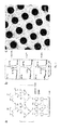
Fig. 1 shows chemical nanolithography of a carbon nanomembrane arranged on a support material via electron irradiation or extreme UV (EUV) light. Electron irradiation of aromatic SAMs results in their lateral cross-linking (A. Turchanin et al., Proc. Surf. Sci. 2012, 87, 108; W. Geyer et al., Appl. Phys. Lett. 1999, 75, 2401; A. Turchanin et al., Langmuir 2009, 25, 7342). The cross-linking converts the SAM into a mechanically stable molecular nanolayer with a thickness of one molecule, which can be tuned from 0.5 to 3 nm (A. Turchanin et al., ACS Nano 2013, 7, 6489;US 8,377,243 B2 ). In case of chemical nanolithography of nitro group-terminated biphenyl SAMs, cross-linked amino-terminated areas in a 4'-nitro-1,1'-biphenyl-4-thiol (NBPT) SAM on gold may be produced. In particular, nitro groups are reduced into the respective amino groups, which may be modified for the preparation of functionalized nanomembranes (US 6,764,758 B1 ). - A similar cross-linking of the aromatic SAMs can be attained with extreme UV (EUV) light. In addition, EUV opens new opportunities for the fabrication of nanopatterned nanomembranes by using EUV interference lithography (EUV-IL). EUV-IL combines the advantages of a parallel fabrication process with very high resolution below 10 nm. Its nanopatterning capability is far beyond that of photolithography, electron beam lithography, and scanning probe lithography, in terms of resolution or throughput. It may be used for making free-standing patterned nanomembranes of various shapes.
- Free-standing carbon nanomembranes may also be chemically functionalized. In some cases, even a second face on the carbon nanomembrane is available for modifications. These free-standing bifacial carbon nanomembranes are usually known as "Janus nanomembranes".
-
Fig. 2 shows a functionalized carbon nanomembrane having PG as biorepulsive material and EDTA as affinity groups. It has been shown that the amino-terminated, cross-linked surfaces could not only be rendered biorepulsive by a grafting process, but can also be modified by acylation chemistry. Preferably, multidentate ligands, such as EDTA, are used as affinity groups, which are capable of reversibly binding Ni2+ ions.Fig. 2b shows X-ray photoelectron spectra (XPS) of a pristine functionalized carbon nanomembrane (top), the same membrane after incubation with Ni2+ (centre) and after removal of Ni2+ with EDTA solution (bottom). - XPS analysis shows that the functionalized carbon nanomembranes bind Ni2+ reversibly, which means that a reversible attachment/detachment of the specimen becomes possible. Furthermore, free-standing PG and EDTA functionalized carbon nanomembrane were transferred from the original gold substrate onto TEM grids.
Fig. 2c shows a low-resolution helium ion microscopy (HIM) image of a free-standing PG and EDTA functionalized carbon nanomembrane on a Quantifoil® TEM grid. - The inventive functionalized nanomembranes may be used as TEM support films for the specific immobilization of biomolecules on their surface via bio-recognition reactions.
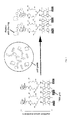
Fig. 3 shows the concept of using the inventive carbon nanomembranes. Selective immobilization of biomolecules is achieved just by immersion of the functionalized nanomembrane into a raw mixture, for example, a cell lysate. The hydrogel intermediate layer prevents the unspecific binding of constituents of the cell lysate to the nanomembrane. The final assembly is suitable for vitrification and subsequent structural analysis by cryoTEM. -
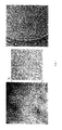
Fig. 4 shows TEM images of His-tagged biomolecules specifically bound to carbon nanomembranes functionalized with PG and EDTA. TEM analysis reveals that His-tagged thermosome molecules bind to functionalized carbon nanomembranes, whereas thermosomes without His-Tag do not bind to functionalized carbon nanomembranes.Fig. 4a shows a TEM image of negatively stained His-tagged thermosome molecules from Pyrococcus furious attached to the functionalized carbon nanomembrane.Fig. 4c shows a TEM image of a control experiment. It shows a functionalized carbon nanomembrane after incubation with bare thermosome without His-Tag and subsequent negative staining. Apart from dark deposits no thermosome particles are visible. -
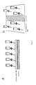
Fig. 5 shows how functionalized carbon nanomembranes can be coupled to graphene to enhance the conductivity to reduce sample charging during the TEM measurements.Fig. 5a shows the deposition of the functionalized nanomembrane onto a separately fabricated graphene sheet. Charges collected or formed in the nanomembrane can be easily transferred to the highly conductive graphene sheet due to the proximity (e.g. by tunneling). InFig. 5b parts of the carbon nanomembrane have been transformed into graphene stripes, e.g. by prolonged local treatment with electrons before the remaining parts of the CNM become functionalized. During TEM analysis of biomolecules, charges are then collected by the conductive graphene stripes, which are electrically grounded. Both strategies keep the samples electrically neutral and reduce scattering effects by charge/charge interaction. - CNMs are prepared by electron irradiation induced crosslinking of 4'-nitro-1,1'-biphenyl-4-thiol (NBPT) self-assembled monolayers (SAMs) on gold. To form the SAMs, 300 nm films of thermally evaporated Au on mica are used. The substrates are cleaned in a UV/ozone-cleaner, rinsed with ethanol and blown dry in a stream of nitrogen. For the SAM formation, two methods can be used. Either the substrates are immersed in a ∼10 mmol solution of NBPT in dry, degassed dimethylformamide (DMF) for 72h in a sealed flask under nitrogen. Afterwards samples are rinsed with DMF and ethanol and blown dry with nitrogen. Alternatively, NBPT is evaporated from a Knudsen cell onto the Au films at vacua better than 10-5 mbar. Crosslinking to the CNM and conversion of the nitro groups to amino groups is achieved in high vacuum (<5*10-7 mbar) with an electron floodgun at an electron energy of 100 eV and a dose of 50 mC/cm2.
- The CNM on its gold-on-mica substrate is deposited into dry and clean polytetrafluoroethylene (PTFE) containers filled with a 10% (w/w) solution of glycidol in dry N-methylpyrrolidinone (NMP). After closing the PTFE vessels tightly, it is heated in an oven to 150 °C for 10 h. After cooling, the films are taken out, washed with NMP, water, and acetone, and then dried in the ambient under exclusion of dust.
- The disodium salt of ethylenediaminotetraacetic acid (Na2EDTA x 2 H2O, 510 mg) was dispersed in dry dimethylformamide (DMF, 15 mL) and thionylchloride (0.3 mL) was added. After stirring at room temperature for 2 h, the mixture was heated to 80 °C for 45 min. After cooling, the film system was immersed immediately in this reaction mixture and shaken at 50 rpm for 2 h. Then the films were taken out and purged with DMF, ethanol, water, and acetone. Drying took place in the ambient under exclusion of dust.
- The functionalized CNMs are transferred onto TEM grids using a protecting layer of poly(methyl methacrylate) (PMMA) dissolved in chlorobenzene or ethyl acetate. This layer is used for mechanical stabilization of the CNMs during the transfer process. Two layers of this polymer of overall thickness of ∼400 nm are spin-coated in sequence onto the CNM. First, a layer of low molecular weight PMMA (50 K), then a layer of high molecular weight PMMA (950 K) are spin-cast each for 30 s at 4000 rpm and cured on a hot plate at 90°C for 5 min. The underlying mica support is separated from the gold/functionalized CNM/PMMA structure by a slight dipping into water of one of the edges/corners of the multilayered sample that finally (after separation) floats on the air/water interface. Further, the sample is transferred by using a mica piece from the water surface to an I2/KI/H2O etching bath (1:4:10) where the gold film is dissolved within 15 min. Then the CNM is transferred to pure water for complete cleaning of the membrane from iodine contamination. Finally, the CNM/PMMA structure is fished out by the target substrate, a TEM grid, and the PMMA layer is dissolved in acetone using a critical point dryer to minimize damage of the freestanding parts.
- The functionalized CNM on a TEM grid was incubated with 3 µl NiCl2 (1 mg/mL Ni2+ in PBS buffer) for 30 seconds and rinsed with distilled water. Subsequently, 3 µl of protein solution (His-tagged thermosome from Pyrococcus furiosus, ∼0.2 mg/ml) were applied to the functionalized CNM for 30 seconds, rinsed with distilled water and negatively stained with 1 % uranylacetate solution. Samples were analyzed in a FEI Tecnai Spirit transmission electron microscope at an accelerating voltage of 120 kV. Images were acquired with a 4k x 4k CCD camera (Gatan).
- The features disclosed in the foregoing description, claims and the drawings may, both separately or in any combination, be material for realizing the invention in diverse forms thereof.
Claims (10)
- Functionalized nanomembranes, comprisinga) a first layer comprising a nanomaterial,b) a second layer comprising a biorepulsive material, the second layer being attached to at least one side of the first layer, andc) affinity groups, attached to the second layer.
- Functionalized nanomembrane according to claim 1, wherein the nanomaterial of the first layer is selected from a carbon nanomembrane, graphene, graphene oxide, a film of amorphous carbon and a nanomembrane of silicon, silicon nitride or silicon dioxide.
- Functionalized nanomembrane according to claim 2, wherein the carbon nanomembrane has a thickness in a range of 0.5-4 nm, more preferably 0.6-3 nm.
- Functionalized nanomembrane according to claims 2 or 3, wherein the functionalized carbon nanomembrane has a thickness in a range of 3-25 nm.
- Functionalized nanomembrane according to any of the preceding claims, wherein the biorepulsive material consists of polyglycerol (PG), polyethyleneglycol (PEG), oligoethyleneglycol (OEG), peptides, proteins, oligo-carbohydrates, or (zwitter-)ionic polymers.
- Functionalized nanomembrane according to any of the preceding claims, wherein the affinity group is one species selected from a specific recognition pair, preferably represented by chelate complexes/oligo-His, biotin/(strept)avidin, or specific DNA/RNA sense/antisense pairs.
- Method for preparing a functionalized nanomembrane according to any of the preceding claims, comprising the stepsa) providing a first layer comprising a nanomaterial,b) functionalization of the first layer with a biorepulsive material for obtaining a second layer comprising the biorepulsive material, andc) functionalization of the second layer with affinity groups.
- Method according to claim 7, wherein the first layer, consisting of the nanomaterial, is a nanomaterial supported on a TEM grid.
- Use of the functionalized nanomembrane, according to any of the claims 1-6, as support film, preferably as support film in transmission electron microscopy (TEM), more preferably cryoTEM, for structural analysis of biomolecules.
- Use of the functionalized nanomembrane according to claim 9, wherein the functionalized nanomembrane is used supported on a TEM grid.
Priority Applications (5)
| Application Number | Priority Date | Filing Date | Title |
|---|---|---|---|
| EP15153106.8A EP3050620A1 (en) | 2015-01-29 | 2015-01-29 | Functionalized nanomembrane, a method for preparation thereof and their use |
| EP16702109.6A EP3250319A1 (en) | 2015-01-29 | 2016-01-29 | Functionalized nanomembrane, a method for preparation thereof and their use |
| CN201680006995.XA CN107249731B (en) | 2015-01-29 | 2016-01-29 | Functionalized nanomembranes, methods of making and uses thereof |
| PCT/EP2016/051923 WO2016120450A1 (en) | 2015-01-29 | 2016-01-29 | Functionalized nanomembrane, a method for preparation thereof and their use |
| US15/546,736 US10794908B2 (en) | 2015-01-29 | 2016-01-29 | Functionalized nanomembrane, a method for preparation thereof and their use |
Applications Claiming Priority (1)
| Application Number | Priority Date | Filing Date | Title |
|---|---|---|---|
| EP15153106.8A EP3050620A1 (en) | 2015-01-29 | 2015-01-29 | Functionalized nanomembrane, a method for preparation thereof and their use |
Publications (1)
| Publication Number | Publication Date |
|---|---|
| EP3050620A1 true EP3050620A1 (en) | 2016-08-03 |
Family
ID=52432713
Family Applications (2)
| Application Number | Title | Priority Date | Filing Date |
|---|---|---|---|
| EP15153106.8A Withdrawn EP3050620A1 (en) | 2015-01-29 | 2015-01-29 | Functionalized nanomembrane, a method for preparation thereof and their use |
| EP16702109.6A Withdrawn EP3250319A1 (en) | 2015-01-29 | 2016-01-29 | Functionalized nanomembrane, a method for preparation thereof and their use |
Family Applications After (1)
| Application Number | Title | Priority Date | Filing Date |
|---|---|---|---|
| EP16702109.6A Withdrawn EP3250319A1 (en) | 2015-01-29 | 2016-01-29 | Functionalized nanomembrane, a method for preparation thereof and their use |
Country Status (4)
| Country | Link |
|---|---|
| US (1) | US10794908B2 (en) |
| EP (2) | EP3050620A1 (en) |
| CN (1) | CN107249731B (en) |
| WO (1) | WO2016120450A1 (en) |
Cited By (5)
| Publication number | Priority date | Publication date | Assignee | Title |
|---|---|---|---|---|
| WO2018202837A1 (en) * | 2017-05-04 | 2018-11-08 | Johann Wolfgang Goethe-Universität Frankfurt am Main | Method for preparing a cross-linked hydrogel nanomembrane, the cross-linked hydrogel nanomembrane, tem grid comprising the same and use thereof |
| WO2020108781A1 (en) * | 2018-11-30 | 2020-06-04 | Cnm Technologies Gmbh | Immobilisation of receptor molecules on surfaces by tetrazine ligation |
| WO2020173952A1 (en) * | 2019-02-25 | 2020-09-03 | Universiteit Antwerpen | Electron microscopy grid |
| WO2020208433A1 (en) * | 2019-04-09 | 2020-10-15 | King Abdullah University Of Science And Technology | A transferrable sample platform containing an exfoliated graphene membrane for the analysis and processing of nanomaterials |
| CN113109370A (en) * | 2021-03-29 | 2021-07-13 | 北京大学 | Porous transmission electron microscope supporting film, ultra-flat graphene electron microscope carrier net and preparation method thereof |
Families Citing this family (7)
| Publication number | Priority date | Publication date | Assignee | Title |
|---|---|---|---|---|
| US20210310910A1 (en) * | 2018-08-20 | 2021-10-07 | The Regents Of The University Of California | Graphene Oxide Affinity Sample Grids for Cyro-EM |
| CN109234263A (en) * | 2018-09-27 | 2019-01-18 | 福建海峡石墨烯产业技术研究院有限公司 | A method of the crosslinked action immobilized enzyme based on adenosine monophosphate and graphene |
| CN109786196B (en) * | 2019-01-23 | 2021-03-02 | 盐城师范学院 | Method for preparing grid of transmission electron microscope |
| GB201904187D0 (en) * | 2019-03-26 | 2019-05-08 | Res & Innovation Uk | Graphene functionalization method, apparatus, and functionalized graphene product |
| CN111912869A (en) * | 2019-10-30 | 2020-11-10 | 清华大学 | Application of reduced graphene oxide film in cryoelectron microscope |
| CN113960089B (en) * | 2020-07-20 | 2023-01-17 | 清华大学 | Multifunctional graphene carrying net and preparation method thereof |
| US20230288299A1 (en) * | 2020-08-21 | 2023-09-14 | Universiteit Gent | Electron microscopy grids and high-resolution structural determination methods |
Citations (6)
| Publication number | Priority date | Publication date | Assignee | Title |
|---|---|---|---|---|
| US6764758B1 (en) | 1999-09-24 | 2004-07-20 | Universitat Heidelberg | Surface-modified layer system |
| WO2009035727A2 (en) * | 2007-05-18 | 2009-03-19 | State Of Oregon Acting By And Through The State Board Of Higher Educ.On Behalf Of The Univ.Of Oregon | Tem grids for determination of structure-property relationships in nanotechnology |
| US20110226413A1 (en) * | 2010-03-17 | 2011-09-22 | Tsinghua University | Carbon nanotube film composite structure, transmission electron microscope grid using the same, and method for making the same |
| WO2012094634A2 (en) * | 2011-01-07 | 2012-07-12 | Dune Sciences, Inc. | Functionalized carbon membranes |
| CN102661882A (en) * | 2012-04-17 | 2012-09-12 | 刘遵峰 | Affinity-based separation transmission electron microscope supporting film based on one-dimensional carbon nanomaterial |
| US8377243B2 (en) | 2007-04-11 | 2013-02-19 | Armin Gölzhäuser | Method for transferring a nanolayer |
Family Cites Families (5)
| Publication number | Priority date | Publication date | Assignee | Title |
|---|---|---|---|---|
| US7781226B2 (en) * | 2004-02-27 | 2010-08-24 | The Board Of Regents Of The University Of Texas System | Particle on membrane assay system |
| US9737593B2 (en) * | 2008-03-19 | 2017-08-22 | Yale University | Carbon nanotube compositions and methods of use thereof |
| US8383237B2 (en) * | 2009-06-01 | 2013-02-26 | University Of Maryland, College Park | Preparation of silica stabilized biological templates for the production of metal and layered nanoparticles |
| WO2011146090A2 (en) * | 2009-11-24 | 2011-11-24 | Kansas State University Research Foundation | Production of graphene nanoribbons with controlled dimensions and crystallographic orientation |
| US8920764B2 (en) * | 2011-02-11 | 2014-12-30 | University of Pittsburgh—of the Commonwealth System of Higher Education | Graphene composition, method of forming a graphene composition and sensor system comprising a graphene composition |
-
2015
- 2015-01-29 EP EP15153106.8A patent/EP3050620A1/en not_active Withdrawn
-
2016
- 2016-01-29 EP EP16702109.6A patent/EP3250319A1/en not_active Withdrawn
- 2016-01-29 CN CN201680006995.XA patent/CN107249731B/en active Active
- 2016-01-29 US US15/546,736 patent/US10794908B2/en active Active
- 2016-01-29 WO PCT/EP2016/051923 patent/WO2016120450A1/en active Application Filing
Patent Citations (6)
| Publication number | Priority date | Publication date | Assignee | Title |
|---|---|---|---|---|
| US6764758B1 (en) | 1999-09-24 | 2004-07-20 | Universitat Heidelberg | Surface-modified layer system |
| US8377243B2 (en) | 2007-04-11 | 2013-02-19 | Armin Gölzhäuser | Method for transferring a nanolayer |
| WO2009035727A2 (en) * | 2007-05-18 | 2009-03-19 | State Of Oregon Acting By And Through The State Board Of Higher Educ.On Behalf Of The Univ.Of Oregon | Tem grids for determination of structure-property relationships in nanotechnology |
| US20110226413A1 (en) * | 2010-03-17 | 2011-09-22 | Tsinghua University | Carbon nanotube film composite structure, transmission electron microscope grid using the same, and method for making the same |
| WO2012094634A2 (en) * | 2011-01-07 | 2012-07-12 | Dune Sciences, Inc. | Functionalized carbon membranes |
| CN102661882A (en) * | 2012-04-17 | 2012-09-12 | 刘遵峰 | Affinity-based separation transmission electron microscope supporting film based on one-dimensional carbon nanomaterial |
Non-Patent Citations (17)
| Title |
|---|
| A. TURCHANIN ET AL., ACS NANO, vol. 7, 2013, pages 6489 |
| A. TURCHANIN ET AL., LANGMUIR, vol. 25, 2009, pages 7342 |
| A. TURCHANIN ET AL., POOC. SURF SCI., vol. 87, 2012, pages 108 |
| B.G. HAN ET AL., J STRUCT. BIOL., vol. 180, 2012, pages 249 |
| CHRISTOPHER J. BENJAMIN ET AL: "Stabilized, Non-Fouling Transmission Electron Microscopy Grid Coatings for the Selective Capture of His-Tag T7 Virus and His-Tag Gro EL from Cell Lysates", BIOPHYSICAL JOURNAL, vol. 108, no. 2, 27 January 2015 (2015-01-27), pages 617a - 618a, XP055202376, ISSN: 0006-3495, DOI: 10.1016/j.bpj.2014.11.3361 * |
| D.F. KELLY ET AL., J MOL. BIOL., vol. 382, 2008, pages 423 |
| EUNAH KANG ET AL: "Specific Adsorption of Histidine-Tagged Proteins on Silica Surfaces Modified with Ni 2+ /NTA-Derivatized Poly(ethylene glycol)", LANGMUIR, vol. 23, no. 11, 1 May 2007 (2007-05-01), pages 6281 - 6288, XP055201770, ISSN: 0743-7463, DOI: 10.1021/la063719e * |
| G. SHARMA ET AL., J STRUCT. BIOL., vol. 181, 2013, pages 190 |
| J.C. MEYER ET AL., NATURE, vol. 454, 2008, pages 319 |
| LLAGUNO ET AL., J STRUCT. BIOL., vol. 185, 2014, pages 405 |
| N. MEYERBROKER, ACS APPL. MAT. INTERF, vol. 5, 2013, pages 5129 |
| R.S. PANTELIC ET AL., J STRUCT. BIOL., vol. 174, 2011, pages 234 |
| R.S. PANTELIC ET AL., J. STRUCT. BIOL., vol. 170, 2010, pages 152 |
| R.S. PANTELIC ET AL., SOLID STATE COMMUN., vol. 152, 2012, pages 1375 |
| W. GEYER ET AL., APPL. PHYS. LCTT., vol. 75, 1999, pages 2401 |
| Y. GUIMEI ET AL., J STRUCT, BIOL., vol. 187, 2014, pages 1 |
| ZUNFENG LIU ET AL: "A Graphene Oxide˙Streptavidin Complex for Biorecognition - Towards Affinity Purification", ADVANCED FUNCTIONAL MATERIALS, vol. 20, no. 17, 9 September 2010 (2010-09-09), pages 2857 - 2865, XP055202293, ISSN: 1616-301X, DOI: 10.1002/adfm.201000761 * |
Cited By (7)
| Publication number | Priority date | Publication date | Assignee | Title |
|---|---|---|---|---|
| WO2018202837A1 (en) * | 2017-05-04 | 2018-11-08 | Johann Wolfgang Goethe-Universität Frankfurt am Main | Method for preparing a cross-linked hydrogel nanomembrane, the cross-linked hydrogel nanomembrane, tem grid comprising the same and use thereof |
| WO2020108781A1 (en) * | 2018-11-30 | 2020-06-04 | Cnm Technologies Gmbh | Immobilisation of receptor molecules on surfaces by tetrazine ligation |
| WO2020173952A1 (en) * | 2019-02-25 | 2020-09-03 | Universiteit Antwerpen | Electron microscopy grid |
| WO2020208433A1 (en) * | 2019-04-09 | 2020-10-15 | King Abdullah University Of Science And Technology | A transferrable sample platform containing an exfoliated graphene membrane for the analysis and processing of nanomaterials |
| US11742174B2 (en) | 2019-04-09 | 2023-08-29 | King Abdullah University Of Science And Technology | Transferrable sample platform containing an exfoliated graphene membrane for the analysis and processing of nanomaterials |
| CN113109370A (en) * | 2021-03-29 | 2021-07-13 | 北京大学 | Porous transmission electron microscope supporting film, ultra-flat graphene electron microscope carrier net and preparation method thereof |
| CN113109370B (en) * | 2021-03-29 | 2022-04-26 | 北京大学 | Porous transmission electron microscope supporting film, ultra-flat graphene electron microscope carrier net and preparation method thereof |
Also Published As
| Publication number | Publication date |
|---|---|
| US20180017558A1 (en) | 2018-01-18 |
| WO2016120450A1 (en) | 2016-08-04 |
| EP3250319A1 (en) | 2017-12-06 |
| CN107249731A (en) | 2017-10-13 |
| CN107249731B (en) | 2020-10-13 |
| US10794908B2 (en) | 2020-10-06 |
Similar Documents
| Publication | Publication Date | Title |
|---|---|---|
| US10794908B2 (en) | Functionalized nanomembrane, a method for preparation thereof and their use | |
| Pantelic et al. | Oxidative doping renders graphene hydrophilic, facilitating its use as a support in biological TEM | |
| Ruckenstein et al. | Surface modification and functionalization through the self-assembled monolayer and graft polymerization | |
| Bagheri et al. | Towards greater mechanical, thermal and chemical stability in solid-phase microextraction | |
| Siqueira Petri et al. | An improved method for the assembly of amino-terminated monolayers on SiO2 and the vapor deposition of gold layers | |
| US8237155B2 (en) | Selective nanotube formation and related devices | |
| Yunus et al. | A route to self‐organized honeycomb microstructured polystyrene films and their chemical characterization by ToF‐SIMS imaging | |
| Schmüser et al. | Candle soot-based super-amphiphobic coatings resist protein adsorption | |
| CN105492385A (en) | Purification process for graphene nano-ribbons | |
| Azucena et al. | New approaches for bottom-up assembly of tobacco mosaic virus-derived nucleoprotein tubes on defined patterns on silica-and polymer-based substrates | |
| Guo et al. | Surface-hydrophilic and protein-resistant silicone elastomers prepared by hydrosilylation of vinyl poly (ethylene glycol) on hydrosilanes-poly (dimethylsiloxane) surfaces | |
| EP3142978A2 (en) | Compositions and methods for micropatterning superhydrophobic surfaces | |
| Cheung et al. | A method to achieve homogeneous dispersion of large transmembrane complexes within the holes of carbon films for electron cryomicroscopy | |
| Scherr et al. | Smart molecular nanosheets for advanced preparation of biological samples in electron cryo-microscopy | |
| Sin et al. | An intuitive thermal-induced surface zwitterionization for versatile, well-controlled haemocompatible organic and inorganic materials | |
| Machata et al. | Wettability of MXene films | |
| Iwasaki et al. | Immobilization of phosphorylcholine polymers to Ti-supported vinyldimethylsilyl monolayers and reduction of albumin adsorption | |
| Nakano et al. | Double-cyclopolymerization using trifunctional incompletely condensed cage silsesquioxane with methacryloyl groups | |
| JP2021522363A (en) | Compositions, Devices, and Methods for Improving Surface Properties of Substrates | |
| KR20200069414A (en) | Graphene complex for electron microscope observation and method for producing sample substrate | |
| Burkarter et al. | Electrosprayed superhydrophobic PTFE: a non-contaminating surface | |
| EP1610909B1 (en) | Controlled surface-chemical gradients | |
| Vlachopoulou et al. | High-aspect-ratio plasma-induced nanotextured poly (dimethylsiloxane) surfaces with enhanced protein adsorption capacity | |
| Kim et al. | Instant Self‐Assembly of Functionalized MXenes in Organic Solvents: General Fabrication to High‐Performance Chemical Gas Sensors | |
| US11578173B2 (en) | Method for preparing a cross-linked hydrogel nanomembrane, the cross-linked hydrogel nanomembrane, TEM grid comprising the same and use thereof |
Legal Events
| Date | Code | Title | Description |
|---|---|---|---|
| PUAI | Public reference made under article 153(3) epc to a published international application that has entered the european phase |
Free format text: ORIGINAL CODE: 0009012 |
|
| AK | Designated contracting states |
Kind code of ref document: A1 Designated state(s): AL AT BE BG CH CY CZ DE DK EE ES FI FR GB GR HR HU IE IS IT LI LT LU LV MC MK MT NL NO PL PT RO RS SE SI SK SM TR |
|
| AX | Request for extension of the european patent |
Extension state: BA ME |
|
| STAA | Information on the status of an ep patent application or granted ep patent |
Free format text: STATUS: THE APPLICATION IS DEEMED TO BE WITHDRAWN |
|
| 18D | Application deemed to be withdrawn |
Effective date: 20170204 |