EP3049825B1 - Determination of the position of a vehicle on or above a planet surface - Google Patents
Determination of the position of a vehicle on or above a planet surface Download PDFInfo
- Publication number
- EP3049825B1 EP3049825B1 EP14793439.2A EP14793439A EP3049825B1 EP 3049825 B1 EP3049825 B1 EP 3049825B1 EP 14793439 A EP14793439 A EP 14793439A EP 3049825 B1 EP3049825 B1 EP 3049825B1
- Authority
- EP
- European Patent Office
- Prior art keywords
- radar
- vehicle
- objects
- froi
- data
- Prior art date
- Legal status (The legal status is an assumption and is not a legal conclusion. Google has not performed a legal analysis and makes no representation as to the accuracy of the status listed.)
- Active
Links
- 238000000034 method Methods 0.000 claims description 29
- 230000003287 optical effect Effects 0.000 claims description 19
- 238000012545 processing Methods 0.000 claims description 10
- 230000005855 radiation Effects 0.000 claims description 7
- 238000004590 computer program Methods 0.000 claims description 4
- 230000001419 dependent effect Effects 0.000 claims description 4
- 238000001514 detection method Methods 0.000 claims description 2
- 238000003860 storage Methods 0.000 claims description 2
- 238000005259 measurement Methods 0.000 description 9
- 238000011161 development Methods 0.000 description 5
- 230000018109 developmental process Effects 0.000 description 5
- 238000011156 evaluation Methods 0.000 description 4
- 230000008569 process Effects 0.000 description 3
- 238000012795 verification Methods 0.000 description 3
- 230000001133 acceleration Effects 0.000 description 2
- 230000004888 barrier function Effects 0.000 description 2
- 230000004927 fusion Effects 0.000 description 2
- 239000002184 metal Substances 0.000 description 2
- 238000004088 simulation Methods 0.000 description 2
- 238000012935 Averaging Methods 0.000 description 1
- 241001465382 Physalis alkekengi Species 0.000 description 1
- 230000006399 behavior Effects 0.000 description 1
- 230000005540 biological transmission Effects 0.000 description 1
- 230000008859 change Effects 0.000 description 1
- 230000000694 effects Effects 0.000 description 1
- 230000036039 immunity Effects 0.000 description 1
- 238000012625 in-situ measurement Methods 0.000 description 1
- 230000004807 localization Effects 0.000 description 1
- 238000012423 maintenance Methods 0.000 description 1
- 239000000463 material Substances 0.000 description 1
- 239000000047 product Substances 0.000 description 1
- 239000007787 solid Substances 0.000 description 1
- 238000012358 sourcing Methods 0.000 description 1
- 239000013589 supplement Substances 0.000 description 1
- 230000009466 transformation Effects 0.000 description 1
- 239000013598 vector Substances 0.000 description 1
Images

Classifications
-
- G—PHYSICS
- G01—MEASURING; TESTING
- G01S—RADIO DIRECTION-FINDING; RADIO NAVIGATION; DETERMINING DISTANCE OR VELOCITY BY USE OF RADIO WAVES; LOCATING OR PRESENCE-DETECTING BY USE OF THE REFLECTION OR RERADIATION OF RADIO WAVES; ANALOGOUS ARRANGEMENTS USING OTHER WAVES
- G01S13/00—Systems using the reflection or reradiation of radio waves, e.g. radar systems; Analogous systems using reflection or reradiation of waves whose nature or wavelength is irrelevant or unspecified
- G01S13/02—Systems using reflection of radio waves, e.g. primary radar systems; Analogous systems
- G01S13/06—Systems determining position data of a target
-
- G—PHYSICS
- G01—MEASURING; TESTING
- G01S—RADIO DIRECTION-FINDING; RADIO NAVIGATION; DETERMINING DISTANCE OR VELOCITY BY USE OF RADIO WAVES; LOCATING OR PRESENCE-DETECTING BY USE OF THE REFLECTION OR RERADIATION OF RADIO WAVES; ANALOGOUS ARRANGEMENTS USING OTHER WAVES
- G01S7/00—Details of systems according to groups G01S13/00, G01S15/00, G01S17/00
- G01S7/02—Details of systems according to groups G01S13/00, G01S15/00, G01S17/00 of systems according to group G01S13/00
- G01S7/41—Details of systems according to groups G01S13/00, G01S15/00, G01S17/00 of systems according to group G01S13/00 using analysis of echo signal for target characterisation; Target signature; Target cross-section
- G01S7/411—Identification of targets based on measurements of radar reflectivity
-
- G—PHYSICS
- G01—MEASURING; TESTING
- G01S—RADIO DIRECTION-FINDING; RADIO NAVIGATION; DETERMINING DISTANCE OR VELOCITY BY USE OF RADIO WAVES; LOCATING OR PRESENCE-DETECTING BY USE OF THE REFLECTION OR RERADIATION OF RADIO WAVES; ANALOGOUS ARRANGEMENTS USING OTHER WAVES
- G01S13/00—Systems using the reflection or reradiation of radio waves, e.g. radar systems; Analogous systems using reflection or reradiation of waves whose nature or wavelength is irrelevant or unspecified
- G01S13/86—Combinations of radar systems with non-radar systems, e.g. sonar, direction finder
-
- G—PHYSICS
- G01—MEASURING; TESTING
- G01S—RADIO DIRECTION-FINDING; RADIO NAVIGATION; DETERMINING DISTANCE OR VELOCITY BY USE OF RADIO WAVES; LOCATING OR PRESENCE-DETECTING BY USE OF THE REFLECTION OR RERADIATION OF RADIO WAVES; ANALOGOUS ARRANGEMENTS USING OTHER WAVES
- G01S13/00—Systems using the reflection or reradiation of radio waves, e.g. radar systems; Analogous systems using reflection or reradiation of waves whose nature or wavelength is irrelevant or unspecified
- G01S13/87—Combinations of radar systems, e.g. primary radar and secondary radar
- G01S13/876—Combination of several spaced transponders or reflectors of known location for determining the position of a receiver
-
- G—PHYSICS
- G01—MEASURING; TESTING
- G01S—RADIO DIRECTION-FINDING; RADIO NAVIGATION; DETERMINING DISTANCE OR VELOCITY BY USE OF RADIO WAVES; LOCATING OR PRESENCE-DETECTING BY USE OF THE REFLECTION OR RERADIATION OF RADIO WAVES; ANALOGOUS ARRANGEMENTS USING OTHER WAVES
- G01S5/00—Position-fixing by co-ordinating two or more direction or position line determinations; Position-fixing by co-ordinating two or more distance determinations
- G01S5/02—Position-fixing by co-ordinating two or more direction or position line determinations; Position-fixing by co-ordinating two or more distance determinations using radio waves
- G01S5/0252—Radio frequency fingerprinting
- G01S5/02521—Radio frequency fingerprinting using a radio-map
- G01S5/02524—Creating or updating the radio-map
- G01S5/02525—Gathering the radio frequency fingerprints
-
- G—PHYSICS
- G01—MEASURING; TESTING
- G01S—RADIO DIRECTION-FINDING; RADIO NAVIGATION; DETERMINING DISTANCE OR VELOCITY BY USE OF RADIO WAVES; LOCATING OR PRESENCE-DETECTING BY USE OF THE REFLECTION OR RERADIATION OF RADIO WAVES; ANALOGOUS ARRANGEMENTS USING OTHER WAVES
- G01S13/00—Systems using the reflection or reradiation of radio waves, e.g. radar systems; Analogous systems using reflection or reradiation of waves whose nature or wavelength is irrelevant or unspecified
- G01S13/86—Combinations of radar systems with non-radar systems, e.g. sonar, direction finder
- G01S13/867—Combination of radar systems with cameras
Definitions
- the invention relates to a device and a method for determining the position of a vehicle on or above a planetary surface, in particular in a traffic route network on the planetary surface.
- vehicle in the present case aircraft, rail vehicles, ships, and in particular motor vehicles (cars, trucks, buses, etc.) understood.
- Satellite-based global navigation systems are systems for determining and navigating the Earth, in the air, or in near-Earth orbit by receiving signals from navigation satellites.
- GNSS is a collective term for the use of existing and future global satellite systems such as GPS (Global Positioning System), GLONASS (GLObal Navigation Satellite System), GALILEO, or COMPASS).
- GPS Global Positioning System
- GLONASS GLObal Navigation Satellite System
- GALILEO GALILEO
- COMPASS COMPASS
- the satellite-based position-finding systems are subject to errors (satellite position errors, time drift errors, ionospheric errors, tropospheric errors, multipath effect errors) which lead to inaccuracies in the determination of the position. These errors can add up and allow a position determination only with an accuracy of 5 to 150 m.
- the signals from satellite positioning systems can be disturbed by jammers.
- An Inertial Navigation System is a sensor system that allows the measurement of movements of bodies that move freely in space. Like the object to be monitored, the system has a total of six kinematic degrees of freedom, of which three are translatory and three rotational, which are also based on three orthogonal unit vectors. With this sensor, the body coordinate system can be determined in real time and compared via a kinematic transformation with a fixed, previously known, spatial coordinate system, which allows an application of the INS as a navigation system. It is one of the main advantages that this can be operated without reference, and therefore is independent of any localization signals from the environment.
- inertial navigation is due to the fact that the acceleration and rotation rate sensors required for setting up an INS determine all changes in the object position and position based on internally built-in, quantitatively known, masses (also called seismic masses) acting accelerations, which is based on the principle of mass inertia .
- a major disadvantage of the INS is the sensor drift, which is particularly strong in the case of very low-cost sensors, whose error influence increases cumulatively in the course of a measurement.
- an INS is coupled with other navigation systems. For example, a combination with a Global Positioning System (GPS) provides absolute position information in one-second intervals, while the INS interpolates the intermediate values.
- GPS Global Positioning System
- Inertial-based positioning systems are subject to positional errors (particularly based on the drift error in combination with, for example, the aforementioned lack of GNSS systems.
- the inertial navigation is too expensive for mass use, for example in cars.
- the GNSS navigation does not always work properly and reliably due to shadowing, multiple reception (reflections, multi-path) and interference (intentionally as well as by means of interference transmitters) of the received signal.
- the road coordinates in the available data sets eg, TomTom and Nokia "HERE", formerly Navteq
- the road coordinates in the available data sets are far from accurate enough to keep a vehicle in lane under autonomous control and to provide driving control.
- a position determination based on optical landmarks using prominent and accurately measured landmarks such. b. Church spire tops, masts and striking buildings known. From the vehicle made photographic recordings or image sequences are compared with an environment image database, the landmarks (control points) found, determines the angle at which the landmarks are seen from the vehicle, and using the known coordinates of the control points and Triangulation determines the position of the vehicle.
- this procedure only works if it is suitable.
- a database with the coordinates of visually identifiable control points from the vehicle does not currently exist.
- the position of the vehicle by GNSS positioning is not accurate enough and in itself not fail-safe and binding enough.
- the road data is not captured accurately enough and the objects / features for accurate referencing are not contain.
- the robust determination of the current vehicle position with a high position accuracy is required.
- driver assistance systems for automatic tracking in autonomously moving motor vehicles require multi-redundant and secure sensors for highly accurate position determination in real time.
- the object of the invention is to provide an apparatus and a method for improved position determination of a vehicle moving on the earth's surface in a traffic route network
- the invention results from the features of the independent claims.
- Advantageous developments and refinements are the subject of the dependent claims.
- Other features, applications and advantages of the invention will become apparent from the following description, as well as the explanation of embodiments of the invention, which are illustrated in the figures.
- An apparatus aspect of the object is achieved with a device for determining the position of a vehicle, which moves on the earth's surface in a traffic route network.
- traffic route network is understood in particular to mean a road traffic network or a navigational network.
- the radar system is designed and set up such that in the fixed point data depends on the first position P1 (t) from the radar objects FRO i those radar objects FRO i * with the associated radar signatures RS FROi * and positions P FROi * can be determined whose positions P FROi * in a predeterminable of the direction of movement BR (t) dependent area around the current first position P1 (t) of the vehicle lying, wherein the fixed point data are generated on the basis of radar data in which the earth's surface and the radar objects FRO i arranged thereon are shown in plan view and then the radar data of the radar objects FRO detected in the radar data in plan i are converted into radar signatures RS FROi , which have the radar objects RO k (t) in side view.
- the first means is implemented and arranged such that the first position P1 (t) of the vehicle is corrected on the basis of the determined second position P2 (t) and / or a position warning is output if the first position P1 (t) and the second position Position P2 (t) differ by more than a predetermined limit.
- the first means is preferably a satellite-based and / or inertia-based position-finding system.
- the first means thus enables a determination of the first position P1 (t) with a given position inaccuracy of ⁇ P1 (t). As stated in the introduction, this is typically in the range of ⁇ 5 to ⁇ 100 m.
- the second means advantageously comprises a magnetic field sensor and / or an inertial system and / or a GNSS system.
- the direction of movement or the direction of travel is typically determined in today's vehicles anyway and is provided in an advantageous development of the corresponding vehicle system.
- the third means provides the checkpoint data.
- These fixed point data indicate on the planetary surface fixedly arranged significant radar objects FRO i , their radar signature RS FROi and their positions P FROi .
- the positions P FROi are included advantageously indicated with a positional accuracy in the range of ⁇ 50 cm, ⁇ 30 cm, ⁇ 25 cm, ⁇ 10 cm, or ⁇ 5 cm.
- the radar signature RS FROi depends in particular on the size, the shape and the materials that make up the radar objects FRO i , and in particular makes it possible to identify and distinguish individual radar objects FRO i .
- the radar objects FRO i are advantageously objects that reflect incident radar radiation (microwaves).
- the main emission angle of the backscattered radar energy depends on the dielectric properties and mechanical properties of the respective radar object FRO i .
- a radar sensor is best used to detect metal surfaces that are oriented to directly reflect the radar-incident microwaves.
- only radar objects FRO i are advantageously used, which can be detected by the radar system from the vehicle because they have an amplitude clearly above the noise level or the backscatter of the background. In the present case, they are therefore referred to as "significant" radar objects.
- radar objects arranged adjacently to the planetary surface are selected in such a way (and thus to radar objects FRO i of the fixed point data) that they have different and thus easily and uniquely identifiable radar signatures RS FROi . This simplifies a unique identification of the radar objects FRO i .
- the fixed point data are generated on the basis of radar data in which the traffic route network and the radar objects FRO i arranged therein are shown in plan view.
- the radar data are detected by means of aircraft-borne or satellite-borne radar sensors.
- methods are known with which radar objects FRO i by means of radar satellites or aircraft-borne radar sensors with a position accuracy of a few centimeters, in particular up to 2 - 10 cm can be detected.
- An area-wide determination of radar objects FRO i is thus possible in relatively short time (a few weeks) for whole countries or continents, so that a sufficient timeliness of the fixed point data can be ensured.
- the radar signatures of the radar objects FRO i which are initially recorded in plan view, are present as radar signatures RS FROi which can be detected by the vehicle.
- the radar sensor of the motor vehicle typically detects the radar objects FRO i in a side view, so that the radar signatures recorded in plan view are converted into radar signatures RS FROi , which have the radar objects FRO i in side view.
- the above-mentioned easy identifiability of the radar objects FRO i by corresponding radar signatures RS FROi and the requirement that the radar amplitude detected by the radar sensor is well above the noise level or the backscatter of the background, in this case on side views of the radar objects FRO i or those views of the radar objects FRO i are detected by the arranged on the vehicle radar sensor.
- special radar reflectors are mounted as radar objects FRO i at suitable positions and at suitable distances on the planetary surface, for example along roads of a traffic route network. It can thus be ensured that along certain routes of the traffic route network a continuous determination of the second position P2 (t) with a correspondingly high position resolution is possible. This is particularly advantageous for driver assistance systems of motor vehicles which require a highly accurate position determination of the vehicle (for example autonomous driving).
- the radar system advantageously comprises an evaluation computer, the first based on the current, determined by the first means first position P1 (t) in the fixed point data P1 (t) from the stored there radar objects FRO i those radar objects FRO i * with the associated radar signatures RS Froi * and positions P FROi * are determined whose positions P FROi * lie in a predeterminable range, which depends on the direction of movement BR (t), around the current first position P1 (t) of the vehicle. With the "faulty" first position P1 (t) an approximate position of the vehicle is available.
- This "approximate" first position P1 (t) now serves to select from the fixed point data those radar objects FRO i * with the associated radar signatures RS FRoi * and exact positions P FROi * , which depend on the vehicle from the current one Movement direction (direction of travel in motor vehicles) should be recognizable from the first position P1 (t). These selected radar objects FRO i * are marked with an asterisk in the present case.
- These selected radar objects FRO i * and their radar signatures RS FROi * are furthermore compared by the radar system / evaluation computer with the radar signatures RS k (t) of the radar objects RO k (t) that were currently detected by the radar sensor.
- the fixed-point data for at least some significant radar objects FRO i comprise optical data OD i which optically identify the corresponding radar objects FRO i that the radar system comprises an optical sensor for the continuous acquisition of image data BD (t) the current environment of the vehicle, and that the radar system is designed and arranged such that the image data BD (t) for the verification of detected in the current environment of the vehicle radar objects RO k (t) or FRO i * are used.
- an additional optical verification of a radar object FRO i * RO k (t) takes place. This increases the robustness and reliability of the determination of the second position P2 (t).
- the image data BD (t) detected by the optical sensor also comprise an infrared light component.
- FRO i * RO k (t) *
- today's radar sensors allow a distance determination with an accuracy of a few centimeters and an angular resolution of 1 ° and below.
- the corresponding positions P ROk (t) * P FROi * , the distances and angles (horizontal angles / azimuth angles) determined from the radar data initially result in a plurality of second positions P2 k (t), from which, for example, by averaging or other algorithms, the second position P2 (t) is determined.
- the first means according to the invention is designed and set up such that the first position P1 (t) of the vehicle is corrected on the basis of the determined second position P2 (t) and / or a position warning is output if the first position P1 (t) and the second position Position P2 (t) differ by more than a predetermined limit.
- the first position P1 (t) of the vehicle is corrected on the basis of the determined second position P2 (t) only if an amount difference
- This first limit value is advantageously determined by the position inaccuracy of the second position P2 (t).
- a position warning is additionally output when the amount difference
- the proposed device thus serves, in particular, for a position-up-date of the first means, ie the first position P1 (t) determined by the first means, by a second position P2 (t) based on fixed-point data, ie highly accurate radar data.
- Control points radar objects FROi
- radar objects FROi and determined by the radar sensor transit time, angle measurements, or recorded radar signatures by triangulation is determined.
- the device In order to recognize and correctly assign the radar objects FRO i to the radar objects RO k (t) detected by the radar sensor, it is necessary for the device to estimate the approximate Position (first position P1 (t)) knows.
- the proposed device can be built from existing and archived radar images a global network of control points radar objects FROi along, for example, the main roads.
- This method is particularly cost-effective, since no in-situ measurements or elaborate aerial surveys are necessary. Even remote or inaccessible regions of the world can thus create the possibility of highly accurate navigation independent of GNSS.
- the required radar sensors on the vehicle are often present in modern road vehicles for collision warning anyway.
- cameras for recording and measuring the control points can also be used.
- the advantages of the proposed device are that it works independently of the weather and the lighting, the distribution and density of radar objects FRO i on the planetary surface is much clearer (more selective and distinctive) than in optical methods.
- the invention further relates to a vehicle, in particular a motor vehicle, with a device as described above.
- a procedural aspect of the object is achieved with a method for determining the position of a vehicle that moves on the earth's surface in a traffic route network.
- a refinement of the proposed method is characterized in that the remote sensing radar data are detected by a radar-borne or satellite-borne radar sensor.
- a refinement of the proposed method is characterized in that the provided fixed point data for at least some significant radar objects FRO i comprise optical data OD i which optically identify the corresponding radar objects FRO i , with an optical sensor continuously image data BD (t) of the current environment of the Vehicle are detected, and the image data BD (t) for verification of detected in the current environment of the vehicle radar objects RO k (t) can be used.
- the present invention particularly describes an additional method which supplements the established methods, such as GNSS, which supplies highly accurate coordinates as well as position data for aligning the vehicle. This makes positioning more secure, reliable, robust and accurate. This is especially necessary for use in autonomous operation of vehicles (roads, rails).
- the object of the invention is further achieved by a computer system having a data processing device, wherein the data processing device is designed such that a method described above is performed on a data processing device.
- control signals can interact with a programmable computer system so that a method described above is performed.
- the object of the invention is achieved by a computer program product with program code stored on a machine-readable carrier for carrying out a method as described above, when the program code is executed on a data processing device.
- the invention relates to a computer program with program codes for carrying out a method described above, when the program runs on a verarbeitunqsvorraum.
- the data processing device can be configured as any known from the prior art computer system.
- an additional and independently operating navigation system for vehicles is specified, which is all-weather and night capable, and constantly checks existing position data in the vehicle and possibly. Improves, and outputs a warning, if there are serious deviations in the determined position data comes.
- the applications of this embodiment are in the navigation of vehicles of any kind (cars, trucks, especially autonomous vehicles, ships, aircraft, drones, ect.), I. Where high interference immunity is required and several systems that operate as independently as possible constantly compare their position results with each other. An important application are so-called “driver assistance systems", which allow a completely autonomous navigation and driving a car.
- a car radar is used, as it is already used for so-called. Lane Change Assistants and collision avoidance in vehicles.
- the car radar is used to measure the range and the horizontal viewing angle (azimuth) of a prominent radar object and its radar signature in the field of vision of the road. Radar objects that are clearly visible with the radar sensor are selected for the evaluation.
- the radar sensor detects metallic objects such as traffic signs, gantries, light poles, guardrails, noise protection walls and general building edges.
- the coordinates of the radar objects / control points preferably relate to point sources on metallic objects which are precisely known to the proposed device, so that the vehicle position can be determined with the radar measurement (distance and angle to the radar object). If several radar objects / control points are visible at the same time from the radar sensor, the own position can be determined even more precisely by triangulation and the measured value receives more weight when comparing with the other navigation systems.
- a control point database (fixed point data) for radar objects (or optical sensors) is set up. It contains the exact coordinates of the prominent points (so-called radar reflectors), which are usually visible from the road.
- the proposed device in the vehicle uses the current position data of the vehicle (first position P1 (t)) supplied (and possibly only roughly known) (by other systems) and extracted from the control point database the control points / fixed point data and their coordinates supposedly well visible from the vehicle.
- the car radar detects the radar objects in the environment and roughly determines their positions with the corresponding coordinates from the fixed point data and compares them with the control point information extracted from the database. If the difference does not exceed a specifiable error measure, it is assumed that a subset of the radar objects stored in the database has been detected. So-called "radar clutter", ie backscattering of other objects or disturbances must be eliminated in this process, or may not be used.
- the proposed radar method has sheltert, since the control points / Radaorebene are better recognizable here, as in an optical image.
- the positioning process is reversed and the highly accurate positions of the control points / radar objects are used to determine the vehicle position.
- the structure of the control point database with the fixed point data can be done by means of measuring vehicles.
- a measuring vehicle equipped with a high-precision position and position sensors travels all relevant roads and uses a high-precision car radar to record all significant / significant radar objects in the vicinity of the road.
- the measuring vehicle can accurately determine the coordinates of the radar objects.
- the vehicles that later the proposed device require only a comparatively inexpensive position and position sensors. It is therefore invested in elaborate, but unique "learning or calibration trips" in order to save effort in the mass products.
- control points / radar objects are identified and the coordinates of the control points / radar objects are determined with the help of the available information (coordinates of the recording location).
- the help of a simulator can be estimated how later the car radar "sees" the control points. In this way one identifies objects that are known from the optical image measurements and makes them usable for night driving with the car radar. Since no new data needs to be collected, this is probably the most cost-effective way to build the control point database / checkpoint data.
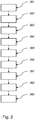
- Fig. 2 shows a schematic representation of a flowchart of a proposed method for determining the position of a vehicle on or over a planetary surface, in particular in a traffic route network on the planetary surface, with the following steps.
- a determination is made of a first position P1 (t) of the vehicle.
- a movement direction BR (t) of the vehicle is determined.
- a fifth step 205 takes place in the fixed point data depending on the first position P1 (t) from the radar objects FRO i determining those radar objects FRO i * with the associated radar signatures RS FROi * and positions P FROi * , their positions P FROi * in one predeterminable region, which depends on the direction of movement BR (t), around the current first position P1 (t) of the vehicle.
- a seventh step 207 the relative positions ⁇ P Ok (t) * of the respective radar objects RO k (t) * are determined on the basis of the radar data to the vehicle.
- an eighth step 208 based on the positions P ROk (t) * and the relative positions ⁇ P Ok (t) *, a determination is made of a second position P2 (t) of the vehicle.
- the first position P1 (t) of the vehicle is corrected on the basis of the determined second position P2 (t) and / or a position warning is issued when the first position P1 (t) and the second position P2 (t) more than a given limit differ.
Landscapes
- Engineering & Computer Science (AREA)
- Radar, Positioning & Navigation (AREA)
- Remote Sensing (AREA)
- Physics & Mathematics (AREA)
- General Physics & Mathematics (AREA)
- Computer Networks & Wireless Communication (AREA)
- Traffic Control Systems (AREA)
- Radar Systems Or Details Thereof (AREA)
- Navigation (AREA)
Description
Die Erfindung betrifft eine Vorrichtung und ein Verfahren zur Positionsbestimmung eines Fahrzeugs auf oder über einer Planetenoberfläche, insbesondere in einem Verkehrswegenetz auf der Planetenoberfläche. Unter dem Begriff "Fahrzeuge" werden vorliegend Flugzeuge, Schienenfahrzeuge, Schiffe, und insbesondere Kraftfahrzeuge (PKW, LKW, Busse etc.) verstanden.The invention relates to a device and a method for determining the position of a vehicle on or above a planetary surface, in particular in a traffic route network on the planetary surface. The term "vehicles" in the present case aircraft, rail vehicles, ships, and in particular motor vehicles (cars, trucks, buses, etc.) understood.
Es ist bekannt, dass heutige Fahrzeuge zu Navigationszwecken mit satellitenbasierten und/oder trägheitsbasierten Positionsermittlungssystemen ausgestattet sind.It is known that today's vehicles are equipped for navigation purposes with satellite-based and / or inertia-based position-finding systems.
Satellitenbasierte globale Navigationssysteme (englisch Global Navigation Satellite System) oder GNSS sind Systeme zur Positionsbestimmung und Navigation auf der Erde, in der Luft, oder im erdnahen Orbit durch den Empfang der Signale von Navigationssatelliten. GNSS ist ein Sammelbegriff für die Verwendung bestehender und künftiger globaler Satellitensysteme wie bspw. GPS (Global Positioning System), GLONASS (GLObal NAvigation Satellite System), GALILEO, oder COMPASS). Bekanntermaßen unterliegen die satellitenbasierten Positionsermittlungssysteme Fehlern (Satellitenpositionsfehler, Zeitdriftfehler, Iononsphärenfehler, Troposphärenfehler, Mehrwege-Effekt-Fehler), die zu Ungenauigkeiten bei der Ermittlung der Position führen. Diese Fehler können sich addieren und lassen eine Positionsermittlung nur mit einer Genauigkeit von 5 bis 150 m zu. Weiterhin ist bekannt, dass die Signale von Satellitenpositionsbestimmungssystemen durch Störsender gestört werden können.Satellite-based global navigation systems (GNSS) are systems for determining and navigating the Earth, in the air, or in near-Earth orbit by receiving signals from navigation satellites. GNSS is a collective term for the use of existing and future global satellite systems such as GPS (Global Positioning System), GLONASS (GLObal Navigation Satellite System), GALILEO, or COMPASS). As is known, the satellite-based position-finding systems are subject to errors (satellite position errors, time drift errors, ionospheric errors, tropospheric errors, multipath effect errors) which lead to inaccuracies in the determination of the position. These errors can add up and allow a position determination only with an accuracy of 5 to 150 m. Furthermore, it is known that the signals from satellite positioning systems can be disturbed by jammers.
Ein Trägheitsnavigationssystem (engl. Inertial Navigation System, kurz INS) ist ein Sensorsystem, mit dessen Hilfe die Messung von Bewegungen von im Raum frei beweglichen Körpern möglich ist. Das System verfügt, wie das zu überwachende Objekt auch, über insgesamt sechs kinematische Freiheitsgrade, davon drei translatorische sowie drei rotatorische, die sich an ebenfalls drei zueinander orthogonal stehenden Einheitsvektoren orientieren. Mit dieser Sensorik lässt sich das Körperkoordinatensystem in Echtzeit bestimmen und über eine kinematische Transformation mit einem feststehenden, vorher bekannten, Raumkoordinatensystem vergleichen, was eine Anwendung des INS als Navigationssystem ermöglicht. Dabei zählt es zu den Hauptvorteilen, dass dieses referenzlos betrieben werden kann, somit also unabhängig von jeglichen Ortungssignalen aus der Umgebung ist.An Inertial Navigation System (INS) is a sensor system that allows the measurement of movements of bodies that move freely in space. Like the object to be monitored, the system has a total of six kinematic degrees of freedom, of which three are translatory and three rotational, which are also based on three orthogonal unit vectors. With this sensor, the body coordinate system can be determined in real time and compared via a kinematic transformation with a fixed, previously known, spatial coordinate system, which allows an application of the INS as a navigation system. It is one of the main advantages that this can be operated without reference, and therefore is independent of any localization signals from the environment.
Der Begriff Trägheitsnavigation rührt daher, dass die zum Aufbau einer INS benötigten Beschleunigungs- und Drehratensensoren sämtliche Änderungen der Objektposition und - lage anhand auf intern verbaute, quantitativ bekannte, Massen (auch seismische Masse genannt) einwirkender Beschleunigungen bestimmen, was auf dem Prinzip der Massenträgheit beruht. Ein wesentlicher Nachteil des INS sind die vor allem bei sehr günstigen Sensoren stark vorhandene Sensordrift, deren Fehlereinfluss sich im Laufe einer Messung kumulativ verstärkt. In der Praxis koppelt man ein INS mit anderen Navigationssystemen. Beispielsweise liefert eine Kombination mit einem Global Positioning System (GPS) absolute Positionsangaben im Sekundenabstand, während das INS die Zwischenwerte interpoliert. Derartige kombinierte Positionsbestimmungssysteme findet man heute in Fahrzeugen und Flugzeugen. Auch Trägheitsbasierte Positionsbestimmungssysteme unterliegen Positionsfehlern (insbesondere basierend auf dem Driftfehler in Kombination mit bspw. den vorgenannten Fehlen bei GNSS-Systemen.The term inertial navigation is due to the fact that the acceleration and rotation rate sensors required for setting up an INS determine all changes in the object position and position based on internally built-in, quantitatively known, masses (also called seismic masses) acting accelerations, which is based on the principle of mass inertia , A major disadvantage of the INS is the sensor drift, which is particularly strong in the case of very low-cost sensors, whose error influence increases cumulatively in the course of a measurement. In practice, an INS is coupled with other navigation systems. For example, a combination with a Global Positioning System (GPS) provides absolute position information in one-second intervals, while the INS interpolates the intermediate values. Such combined positioning systems can be found today in vehicles and aircraft. Also, inertial-based positioning systems are subject to positional errors (particularly based on the drift error in combination with, for example, the aforementioned lack of GNSS systems.
Die Trägheitsnavigation ist jedoch für den Masseneinsatz bspw. in PKW's zu teuer. Die GNSS Navigation arbeitet aufgrund von Abschattungen, Mehrfachempfang (Reflexionen, Multi-Path) und Störungen (unbewusst wie auch mittels Stör-Sendern beabsichtigt) des Empfangssignals nicht immer einwandfrei und verlässlich. Weiterhin sind auch bspw. die Straßen-Koordinaten in den verfügbaren Datensätzen (z. b. von TomTom und Nokia "HERE", ehem. Navteq) bei weitem nicht genau genug, um ein Fahrzeug bei autonomer Steuerung in der Spur zu halten und die Fahrsteuerung zu ermöglichen.However, the inertial navigation is too expensive for mass use, for example in cars. The GNSS navigation does not always work properly and reliably due to shadowing, multiple reception (reflections, multi-path) and interference (intentionally as well as by means of interference transmitters) of the received signal. Further, for example, the road coordinates in the available data sets (eg, TomTom and Nokia "HERE", formerly Navteq) are far from accurate enough to keep a vehicle in lane under autonomous control and to provide driving control.
Weiterhin ist eine Positionsermittlung anhand optischer Landmarken mit Hilfe von prominenten und genau vermessenen Landmarken, wie z. b. Kirchturm-Spitzen, Masten und markanten Gebäuden bekannt. Vom Fahrzeug aus gemachte fotografische Aufnahmen bzw. Bild-Sequenzen werden dabei mit einer Umgebungs-Bilddatenbank verglichen, die Landmarken (Passpunkte) gefunden, die Winkel bestimmt, unter denen die Landmarken vom Fahrzeug aus gesehen werden, und mit Hilfe der bekannten Koordinaten der Passpunkte und Triangulation die Position des Fahrzeugs bestimmt. Dieses Verfahren funktioniert aber nur bei geeigneter Sicht. Eine Datenbank mit den Koordinaten von vom Fahrzeug aus visuell gut identifizierbarer Passpunkte existiert derzeit nicht.Furthermore, a position determination based on optical landmarks using prominent and accurately measured landmarks, such. b. Church spire tops, masts and striking buildings known. From the vehicle made photographic recordings or image sequences are compared with an environment image database, the landmarks (control points) found, determines the angle at which the landmarks are seen from the vehicle, and using the known coordinates of the control points and Triangulation determines the position of the vehicle. However, this procedure only works if it is suitable. A database with the coordinates of visually identifiable control points from the vehicle does not currently exist.
Die Fahrzeug-Position durch GNSS-Ortung ist nicht genau genug und für sich allein nicht ausfallsicher und verbindlich genug. Hinzu kommt, dass die Straßendaten nicht präzise genug erfasst sind und die Objekte / Features zur genauen Referenzierung nicht enthalten. Für eine hochgenaue Fahrzeugführung, bspw. bei künftigen autonom gesteuerten PKWs, Flugzeugen, Schiffen, Schienenfahrzeugen ist die robuste Bestimmung der aktuellen Fahrzeugposition mit einer hohen Positionsgenauigkeit erforderlich. So benötigen insbesondere Fahrer-Assistenz-Systeme zur automatischen Spurhaltung bei sich autonom bewegenden Kraftfahrzeugen eine mehrfach redundante und abgesicherte Sensorik zur hochgenauen Positionsermittlung in Echtzeit.The position of the vehicle by GNSS positioning is not accurate enough and in itself not fail-safe and binding enough. In addition, the road data is not captured accurately enough and the objects / features for accurate referencing are not contain. For a high-precision vehicle guidance, for example in future autonomously controlled cars, aircraft, ships, rail vehicles, the robust determination of the current vehicle position with a high position accuracy is required. For example, driver assistance systems for automatic tracking in autonomously moving motor vehicles require multi-redundant and secure sensors for highly accurate position determination in real time.
Zur Positionsbestimmung von Luftfahrzeugen sind eine Reihe von Veröffentlichungen bekannt. Vergleiche hierzu beispielsweise:
Die Aufgabe der Erfindung ist es eine Vorrichtung und ein Verfahren zur verbesserten Positionsbestimmung eines Fahrzeugs, das sich auf der Erdoberfläche in einem Verkehrswegenetz bewegt, anzugeben
Die Erfindung ergibt sich aus den Merkmalen der unabhängigen Ansprüche. Vorteilhafte Weiterbildungen und Ausgestaltungen sind Gegenstand der abhängigen Ansprüche. Weitere Merkmale, Anwendungsmöglichkeiten und Vorteile der Erfindung ergeben sich aus der nachfolgenden Beschreibung, sowie der Erläuterung von Ausführungsbeispielen der Erfindung, die in den Figuren dargestellt sind.The object of the invention is to provide an apparatus and a method for improved position determination of a vehicle moving on the earth's surface in a traffic route network
The invention results from the features of the independent claims. Advantageous developments and refinements are the subject of the dependent claims. Other features, applications and advantages of the invention will become apparent from the following description, as well as the explanation of embodiments of the invention, which are illustrated in the figures.
Ein vorrichtungsgemäßer Aspekt der Aufgabe ist mit einer Vorrichtung zur Positionsbestimmung eines Fahrzeugs, das sich auf der Erdoberfläche in einem Verkehrswegenetz bewegt, gelöst. Unter dem Begriff "Verkehrswegenetz" wird vorliegend insbesondere ein Straßenverkehrsnetz oder ein Schifffahrtswegenetz verstanden.An apparatus aspect of the object is achieved with a device for determining the position of a vehicle, which moves on the earth's surface in a traffic route network. In the present case, the term "traffic route network" is understood in particular to mean a road traffic network or a navigational network.
Die vorgeschlagene Vorrichtung umfasst ein erstes Mittel zur Bestimmung einer ersten Position P1(t) des Fahrzeugs, ein zweites Mittel zur Bestimmung einer Bewegungsrichtung BR(t) des Fahrzeugs, ein drittes Mittel zur Bereitstellung einer Anzahl n von Fixpunktdaten, wobei die Fixpunktdaten zumindest für auf der Erdnoberfläche ortsfest angeordnete signifikante Radarobjekte FROi deren Radarsignatur RSFROi und deren Position PFROi angeben, mit i = 1, 2,..., n, und ein Radarsystem mit einem am Fahrzeug angeordneten Radarsensor zur Abtastung einer aktuellen Umgebung des Fahrzeugs mittels Radarstrahlung und zur kontinuierlichen Erfassung dabei gewonnener Radardaten, wobei aus den Radardaten für eine Anzahl m von in der Umgebung vorhandenen Radarobjekten ROk(t) deren Radarsignaturen RSk(t) und deren relative Positionen ΔPOk(t) zum Fahrzeug ermittelbar sind, mit k = 0, 1, 2, ..., m. Das Radarsystem ist dabei derart ausgeführt und eingerichtet, dass in den Fixpunktdaten abhängig von der ersten Position P1(t) aus den Radarobjekten FROi diejenigen Radarobjekte FROi* mit den zugehörigen Radarsignaturen RSFROi* und Positionen PFROi* ermittelbar sind, deren Positionen PFROi* in einem vorgebbaren von der Bewegungsrichtung BR(t) abhängigen Bereich um die aktuelle erste Position P1(t) des Fahrzeugs liegenden, , wobei die Fixpunktdaten auf Basis von Radardaten erzeugt sind, in denen die Erdoberfläche und die darauf angeordneten Radarobjekte FROi in Aufsicht abgebildet sind und anschließend die in den Radardaten in Aufsicht erfassten Radarsignaturen der Radarobjekte FROi in Radarsignaturen RSFROi umgewandelt sind, die die Radarobjekte ROk(t) in Seitenansicht aufweisen.The proposed device comprises a first means for determining a first position P1 (t) of the vehicle, a second means for determining a direction of movement BR (t) of the vehicle, a third means for providing a number n of fixed point data, wherein the fixed point data at least for indicate radar objects FRO i whose radar signature RS FROi and their position P FROi are stationary with i = 1, 2,..., n, and a radar system with a radar sensor arranged on the vehicle for scanning a current surroundings of the vehicle by means of radar radiation and for the continuous detection of radar data obtained thereby, it being possible to determine from the radar data for a number m of radar objects RO k (t) present in the environment their radar signatures RS k (t) and their relative positions ΔP Ok (t) with k = 0, 1, 2, ..., m. The radar system is designed and set up such that in the fixed point data depends on the first position P1 (t) from the radar objects FRO i those radar objects FRO i * with the associated radar signatures RS FROi * and positions P FROi * can be determined whose positions P FROi * in a predeterminable of the direction of movement BR (t) dependent area around the current first position P1 (t) of the vehicle lying, wherein the fixed point data are generated on the basis of radar data in which the earth's surface and the radar objects FRO i arranged thereon are shown in plan view and then the radar data of the radar objects FRO detected in the radar data in plan i are converted into radar signatures RS FROi , which have the radar objects RO k (t) in side view.
Das Radarsystem ist weiterhin derart ausgeführt und eingerichtet, dass die Radarsignaturen RSFROi* der Radarobjekte FROi* mit den Radarsignaturen RSk(t) der Radarobjekte ROk(t) verglichen werden, und dabei diejenigen Radarobjekte ROk(t)* ermittelbar sind, für die gilt: RSk(t) = RSFROi*, wobei bei Vorliegen dieser Bedingung unterstellt wird, dass für die Radarobjekte gilt: ROk(t)* = FROi* und für Positionen PRok(t)* der Radarobjekte ROk(t)* gilt: PROk(t)* = PFROi*, weiterhin dass auf Basis der Radardaten die relativen Positionen ΔPOk(t)* der jeweiligen Radarobjekte ROk(t)* zu dem Fahrzeug ermittelt werden, und dass auf Basis jeweils der Positionen PROk(t)* = PFROi* und der relativen Positionen ΔPOk(t)* eine zweite Position P2(t) des Fahrzeugs ermittelt wird. Schließlich ist das erste Mittel derart ausgeführt und eingerichtet, dass die erste Position P1(t) des Fahrzeugs auf Basis der ermittelten zweiten Position P2(t) korrigiert und/oder eine Positionswarnung ausgegeben wird, wenn die erste Position P1(t) und die zweite Position P2(t) um mehr als ein vorgegebener Grenzwert voneinander abweichen.The radar system is furthermore designed and set up such that the radar signatures RS FROi * of the radar objects FRO i * are compared with the radar signatures RS k (t) of the radar objects RO k (t), and in so doing, those radar objects RO k (t) * can be determined for which applies: RS k (t) = RS FROi * , assuming that this condition implies that the following applies to the radar objects: RO k (t) * = FRO i * and for positions P Rok (t) * of the radar objects RO k (t) * holds: P ROk (t) * = P FROi * , further that the relative positions ΔP Ok (t) * of the respective radar objects RO k (t) * to the vehicle are determined on the basis of the radar data, and in that a second position P2 (t) of the vehicle is determined on the basis of the positions P ROk (t) * = P FROi * and the relative positions ΔP Ok (t) *, respectively. Finally, the first means is implemented and arranged such that the first position P1 (t) of the vehicle is corrected on the basis of the determined second position P2 (t) and / or a position warning is output if the first position P1 (t) and the second position Position P2 (t) differ by more than a predetermined limit.
Das erste Mittel ist bevorzugt ein satellitenbasiertes und/oder trägheitsbasiertes Positionsermittlungssystem. Das erste Mittel ermöglicht mithin eine Bestimmung der ersten Position P1(t) mit einer gegebenen Positionsungenauigkeit von ΔP1(t). Diese liegt, wie in der Einleitung ausgeführt, typischer Weise im Bereich von ± 5 bis ± 100 m.The first means is preferably a satellite-based and / or inertia-based position-finding system. The first means thus enables a determination of the first position P1 (t) with a given position inaccuracy of ΔP1 (t). As stated in the introduction, this is typically in the range of ± 5 to ± 100 m.
Das zweite Mittel umfasst vorteilhaft einen Magnetfeldsensor und/oder ein Trägheitssystem und/oder ein GNSS System. Die Bewegungsrichtung bzw. die Fahrtrichtung wird in heutigen Fahrzeugen typischerweise ohnehin ermittelt und wird in einer vorteilhaften Weiterbildung von dem entsprechenden Fahrzeugsystem bereitgestellt.The second means advantageously comprises a magnetic field sensor and / or an inertial system and / or a GNSS system. The direction of movement or the direction of travel is typically determined in today's vehicles anyway and is provided in an advantageous development of the corresponding vehicle system.
Das dritte Mittel stellt die Fixpunktdaten bereit. Diese Fixpunktdaten geben auf der Planetenoberfläche ortsfest angeordnete signifikante Radarobjekte FROi, deren Radarsignatur RSFROi und deren Positionen PFROi an. Die Positionen PFROi sind dabei vorteilhaft mit einer Positionsgenauigkeit im Bereich von < 50 cm, < 30 cm, < 25 cm, < 10 cm, oder < 5 cm angegeben. Die Radarsignatur RSFROi hängt insbesondere von der Größe, der Formgebung und den Materialien ab, aus denen das Radarobjekte FROi besteht, und ermöglicht insbesondere eine Identifizierung und Unterscheidung einzelner Radarobjekte FROi.The third means provides the checkpoint data. These fixed point data indicate on the planetary surface fixedly arranged significant radar objects FRO i , their radar signature RS FROi and their positions P FROi . The positions P FROi are included advantageously indicated with a positional accuracy in the range of <50 cm, <30 cm, <25 cm, <10 cm, or <5 cm. The radar signature RS FROi depends in particular on the size, the shape and the materials that make up the radar objects FRO i , and in particular makes it possible to identify and distinguish individual radar objects FRO i .
Die Radarobjekte FROi sind vorliegend vorteilhaft Gegenstände, die auftreffende RadarStrahlung (Mikrowellen) reflektieren. Der Haupt-Abstrahl-Winkel der rückgestreuten Radarenergie hängt dabei von den dielektrischen Eigenschaften und mechanischen Eigenschaften des jeweiligen Radarobjektes FROi ab. Mit einem Radarsensor erkennt man am besten Metallflächen, die so ausgerichtet sind, dass sie die vom Radar einfallenden Mikrowellen direkt reflektieren. Für die vorliegende Anwendung werden vorteilhaft nur Radarobjekte FROi verwendet, die von dem Fahrzeug aus vom Radarsystem erfasst bzw. gesehen werden können, weil sie eine Amplitude deutlich über dem Rausch-Niveau bzw. der Rückstreuung des Hintergrunds aufweisen. Vorliegend werden sie deshalb als "signifikante" Radarobjekte bezeichnet. Vorteilhaft werden an der Planetenoberfläche benachbart angeordnete Radarobjekte derart ausgewählt (und damit zu Radarobjekten FROi der Fixpunktdaten), dass sie unterschiedliche und somit leicht und eindeutig identifizierbare Radarsignaturen RSFROi aufweisen. Dies vereinfacht eine eindeutige Identifikation der Radarobjekte FROi.In the present case, the radar objects FRO i are advantageously objects that reflect incident radar radiation (microwaves). The main emission angle of the backscattered radar energy depends on the dielectric properties and mechanical properties of the respective radar object FRO i . A radar sensor is best used to detect metal surfaces that are oriented to directly reflect the radar-incident microwaves. For the present application, only radar objects FRO i are advantageously used, which can be detected by the radar system from the vehicle because they have an amplitude clearly above the noise level or the backscatter of the background. In the present case, they are therefore referred to as "significant" radar objects. Advantageously, radar objects arranged adjacently to the planetary surface are selected in such a way (and thus to radar objects FRO i of the fixed point data) that they have different and thus easily and uniquely identifiable radar signatures RS FROi . This simplifies a unique identification of the radar objects FRO i .
Erfindungsgemäß sind die Fixpunktdaten auf Basis von Radardaten erzeugt, in denen das Verkehrswegenetz und die darin angeordneten Radarobjekte FROi in Aufsicht abgebildet sind. Vorteilhaft werden die Radardaten hierbei mittels flugzeuggetragener oder satellitengetragener Radarsensoren erfasst. Hierzu sind Verfahren bekannt, mit denen Radarobjekte FROi mittels Radarsatelliten oder luftfahrzeuggetragener Radarsensoren mit einer Positionsgenauigkeit von wenigen Zentimetern insbesondere bis zu 2 - 10 cm erfasst werden können. Eine flächendeckende Ermittlung von Radarobjekten FROi ist somit in relativ kurzer Zeit (wenige Wochen) für ganze Länder oder Kontinente möglich, so dass eine hinreichende Aktualität der Fixpunktdaten gewährleistet werden kann.According to the invention, the fixed point data are generated on the basis of radar data in which the traffic route network and the radar objects FRO i arranged therein are shown in plan view. Advantageously, the radar data are detected by means of aircraft-borne or satellite-borne radar sensors. For this purpose, methods are known with which radar objects FRO i by means of radar satellites or aircraft-borne radar sensors with a position accuracy of a few centimeters, in particular up to 2 - 10 cm can be detected. An area-wide determination of radar objects FRO i is thus possible in relatively short time (a few weeks) for whole countries or continents, so that a sufficient timeliness of the fixed point data can be ensured.
Hochgenaue absolute Koordinaten der Radarobjekte FROi aus Satelliten-Daten können somit sehr kosteneffektiv weltweit bestimmt werden. Während optische Bilder eine relativ gleichmäßige Helligkeit aufweisen, treten bei Radar-Bildern Gegenstände aus Metall (Leitplanken, Masten, Laternen, Schilderbrücken, Brückengeländer) sehr viel stärker hervor, als der das Hintergrundbild mit dem Straßenbelag und der Vegetation. Sie sind daher wesentlich besser identifizierbar. Weiterhin streuen Gebäudekanten und -Ecken sehr gut. Oft ergeben sich sog. "Radar-Punktziele", die wesentlich kleiner als eine Auflösungszelle (1m x 1m im TerraSAR-X Spotlight Mode Bild) sind. Die Arbeiten von Balss, et al. (DLR MF-SAR) haben gezeigt, dass derartige "Punktziele" in TerraSAR-X und TanDEM-X Radar-Bildern mit einer Genauigkeit von wenigen Zentimetern bestimmt werden können (vgl. hierzu http://elib.dlr.de/82537/).High-precision absolute coordinates of the radar objects FRO i from satellite data can thus be determined very cost-effectively worldwide. While optical images have relatively uniform brightness, metal objects (crash barriers, masts, lanterns, gantries, bridge railings) are much more prominent in radar images than the background image of the road surface and vegetation. They are therefore much easier to identify. Furthermore, building edges and corners scatter very well. Frequently, so-called "radar point targets" result, which are much smaller than a resolution cell (1m x 1m in the TerraSAR-X Spotlight Mode image). The work of Balss, et al. (DLR MF-SAR) have shown that such "point targets" in TerraSAR-X and TanDEM-X radar images can be determined with an accuracy of a few centimeters (see http://elib.dlr.de/82537/ ).
Erfindungsgemäß liegen die zunächst in Aufsicht erfassten Radarsignaturen der Radarobjekte FROi als Radarsignaturen RSFROi vor, die von dem Fahrzeug erfassbar sind. Bei der erfindungsgemäßen Anwendung für den Kraftfahrzeugverkehr, erfasst der Radarsensor des Kraftfahrzeugs die Radarobjekte FROi typischerweise in einer Seitenansicht, so dass die in Aufsicht erfassten Radarsignaturen in Radarsignaturen RSFROi umgewandelt sind, die die Radarobjekte FROi in Seitenansicht aufweisen. Natürlich bezieht sich die vorstehend genannte leichte Identifizierbarkeit der Radarobjekte FROi durch entsprechende Radarsignaturen RSFROi und die Forderung, dass die vom Radarsensor erfasste Radar-Amplitude deutlich über dem Rausch-Niveau bzw. der Rückstreuung des Hintergrunds liegt, in diesem Fall auf Seitenansichten der Radarobjekte FROi bzw. auf diejenigen Ansichten der Radarobjekte FROi die von dem am Fahrzeug angeordneten Radarsensor erfasst werden.According to the invention, the radar signatures of the radar objects FRO i , which are initially recorded in plan view, are present as radar signatures RS FROi which can be detected by the vehicle. In the application according to the invention for motor vehicle traffic, the radar sensor of the motor vehicle typically detects the radar objects FRO i in a side view, so that the radar signatures recorded in plan view are converted into radar signatures RS FROi , which have the radar objects FRO i in side view. Of course, the above-mentioned easy identifiability of the radar objects FRO i by corresponding radar signatures RS FROi and the requirement that the radar amplitude detected by the radar sensor is well above the noise level or the backscatter of the background, in this case on side views of the radar objects FRO i or those views of the radar objects FRO i are detected by the arranged on the vehicle radar sensor.
Vorteilhaft werden spezielle Radarreflektoren als Radarobjekte FROi an geeigneten Positionen und in geeigneten Abständen auf der Planetenoberfläche angebracht, bspw. entlang von Straßen eines Verkehrsstraßennetzes. So kann gewährleistet werden, dass entlang bestimmter Routen des Verkehrsstraßennetzes eine kontinuierliche Ermittlung der zweiten Position P2(t) mit einer entsprechend hohen Positionsauflösung möglich ist. Das ist insbesondere für Fahrerassistenzsysteme von Kraftfahrzeugen von Vorteil, die eine hochgenaue Positionsbestimmung des Fahrzeugs erfordern (bspw. autonomes Fahren).Advantageously, special radar reflectors are mounted as radar objects FRO i at suitable positions and at suitable distances on the planetary surface, for example along roads of a traffic route network. It can thus be ensured that along certain routes of the traffic route network a continuous determination of the second position P2 (t) with a correspondingly high position resolution is possible. This is particularly advantageous for driver assistance systems of motor vehicles which require a highly accurate position determination of the vehicle (for example autonomous driving).
Das Radarsystem umfasst vorteilhaft einen Auswerterechner, mit dem zunächst auf Basis der aktuellen, vom ersten Mittel ermittelten ersten Position P1(t) in den Fixpunktdaten P1(t) aus den dort hinterlegten Radarobjekten FROi diejenigen Radarobjekte FROi* mit den zugehörigen Radarsignaturen RSFROi* und Positionen PFROi* ermittelt werden, deren Positionen PFROi* in einem vorgebbaren von der Bewegungsrichtung BR(t) abhängigen Bereich um die aktuelle erste Position P1(t) des Fahrzeugs liegenden. Mit der "fehlerbehafteten" ersten Position P1(t) steht eine ungefähre Position des Fahrzeugs zur 'Verfügung. Diese "ungefähre" erste Position P1(t) dient nun dazu aus den Fixpunktdaten diejenigen Radarobjekte FROi* mit den zugehörigen Radarsignaturen RSFRoi* und exakten Positionen PFROi* auszuwählen, die vom Fahrzeug aus abhängig von der aktuellen Bewegungsrichtung (Fahrtrichtung bei Kraftfahrzeugen) von der ersten Position P1(t) erkennbar sein sollten. Diese ausgewählten Radarobjekte FROi* sind vorliegend mit einem Stern gekennzeichnet.The radar system advantageously comprises an evaluation computer, the first based on the current, determined by the first means first position P1 (t) in the fixed point data P1 (t) from the stored there radar objects FRO i those radar objects FRO i * with the associated radar signatures RS Froi * and positions P FROi * are determined whose positions P FROi * lie in a predeterminable range, which depends on the direction of movement BR (t), around the current first position P1 (t) of the vehicle. With the "faulty" first position P1 (t) an approximate position of the vehicle is available. This "approximate" first position P1 (t) now serves to select from the fixed point data those radar objects FRO i * with the associated radar signatures RS FRoi * and exact positions P FROi * , which depend on the vehicle from the current one Movement direction (direction of travel in motor vehicles) should be recognizable from the first position P1 (t). These selected radar objects FRO i * are marked with an asterisk in the present case.
Diese ausgewählten Radarobjekte FROi* und deren Radarsignaturen RSFROi* werden weiterhin vom Radarsystem /Auswerterechner mit den Radarsignaturen RSk(t) der Radarobjekte ROk(t) verglichen, die vom Radarsensor aktuell erfasst wurden. Dabei werden diejenigen Radarobjekte ROk(t)* ermittelt, deren Radarsignatur RSk(t) einer Radarsignatur RSFROi* entspricht, d.h. für die gilt: RSk(t) = RSFROi* Bei bei Vorliegen dieser Bedingung wird weiterhin unterstellt, dass für die Radarobjekte gilt: ROk(t)* = FROi* und für Positionen PROk(t)* der Radarobjekte ROk(t)* gilt: PROk(t)* = PFROi*. Mit anderen Worten wird, sofern der Vergleich einer vom Radarsensor erfassten Radarsignatur RSk(t) mit einer ausgewählten Radarsignaturen RSFROi* eine eindeutige Übereinstimmung ergibt, eine Identifikation des zugeordneten Radarobjekte FROi* in den vom Radarsensor erfassten Radardaten unterstellt.These selected radar objects FRO i * and their radar signatures RS FROi * are furthermore compared by the radar system / evaluation computer with the radar signatures RS k (t) of the radar objects RO k (t) that were currently detected by the radar sensor. In this case, those radar objects RO k (t) * are determined whose radar signature RS k (t) corresponds to a radar signature RS FROi * , ie for the following: RS k (t) = RS FROi * If this condition is satisfied, it is further assumed that for the radar objects: RO k (t) * = FRO i * and for positions P ROk (t) * of the radar objects RO k (t) * the following applies: P ROk (t) * = P FROi * . In other words, if the comparison of a radar signature RS k (t) detected by the radar sensor with a selected radar signature RS FROi * results in a clear match, an identification of the associated radar object FRO i * in the radar data acquired by the radar sensor is assumed.
Kommt es bei dem Vergleich zu keiner eindeutigen Identifikation einer Radarsignatur RSFROi* wird das Erfassen aktueller Radardaten mittels des Radarsensors und die anschließende vorstehend beschriebene Auswertung kontinuierlich fortgesetzt, bis zumindest ein Radarobjekt FROi* = ROk(t) eindeutig identifiziert ist.If there is no clear identification of a radar signature RS FROi during the comparison, the acquisition of current radar data by means of the radar sensor and the subsequent evaluation described above are continued continuously until at least one radar object FRO i * = RO k (t) is uniquely identified.
Eine vorteilhafte Weiterbildung der Vorrichtung zeichnet sich dadurch aus, dass die Fixpunktdaten für zumindest einige signifikante Radarobjekte FROi optische Daten ODi umfassen, die die entsprechenden Radarobjekte FROi optisch kennzeichnen, dass das Radarsystem einen optischen Sensor zur kontinuierlichen Erfassung von Bilddaten BD(t) der aktuellen Umgebung des Fahrzeugs aufweist, und dass das Radarsystem derart ausgeführt und eingerichtet ist, dass die Bilddaten BD(t) zur Verifikation von in der aktuellen Umgebung des Fahrzeugs erkannten Radarobjekte ROk(t) bzw. FROi* verwendet werden. In dieser Weiterbildung erfolgt mithin eine zusätzliche optische Verifikation eines Radarobjekts FROi* = ROk(t). Dadurch wird die Robustheit und Zuverlässigkeit der Ermittlung der zweiten Position P2(t) erhöht. Vorteilhaft umfassen die vom optischen Sensor erfassten Bilddaten BD(t) auch einen infraroten Lichtanteil. Mit der Identifikation zumindest eines Radarobjekts FROi* = ROk(t)* ist die diesem Radarobjekt zugeordnete Position PROk(t)* = PFROi* aus den Fixpunktdaten mit hoher Positionsgenauigkeit bekannt.An advantageous development of the device is characterized in that the fixed-point data for at least some significant radar objects FRO i comprise optical data OD i which optically identify the corresponding radar objects FRO i that the radar system comprises an optical sensor for the continuous acquisition of image data BD (t) the current environment of the vehicle, and that the radar system is designed and arranged such that the image data BD (t) for the verification of detected in the current environment of the vehicle radar objects RO k (t) or FRO i * are used. In this development, therefore, an additional optical verification of a radar object FRO i * = RO k (t) takes place. This increases the robustness and reliability of the determination of the second position P2 (t). Advantageously, the image data BD (t) detected by the optical sensor also comprise an infrared light component. With the identification of at least one radar object FRO i * = RO k (t) *, the position P ROk (t) * = P FROi * assigned to this radar object is known from the fixed point data with high position accuracy .
Das Radarsystem ist weiterhin erfindungsgemäß derart ausgeführt und eingerichtet, dass auf Basis der vom Radarsensor erfassten Radardaten die relativen Positionen ΔPOk(t)* der jeweiligen Radarobjekte ROk(t)* = FROi* zu dem Fahrzeug ermittelt werden. Hierzu erlauben heutige Radarsensoren eine Distanzermittlung mit einer Genauigkeit von wenigen Zentimetern und einer Winkelauflösung von 1° und darunter. Somit kann mittels Triangulation (Position, Distanz, Winkel) auf Basis jeweils der Positionen PROk(t)* = PFROi* und der zugehörigen relativen Positionen ΔPOk(t)* eine zweite Position P2(t) des Fahrzeugs ermittelt werden. Wird nur ein Radarobjekt ROk(t)* = FROi* identifiziert, dann ergibt sich aus der Position PROk(t)* = PFROi*, der aus den Radardaten ermittelten Distanz und dem Winkel zu dem einen Radarobjekt ROk(t)* = FROi* die Position P2(t) mit einer Positionsgenauigkeit im Bereich bspw. von 2 bis 50 cm. Werden mehrere Radarobjekte ROk(t)* = FROi* identifiziert, dann ergeben sich aus den entsprechenden Positionen PROk(t)* = PFROi*, den aus den Radardaten ermittelten Distanzen und Winkeln (Horizontalwinkeln/ Azimutwinkeln) zunächst mehrere zweite Positionen P2k(t), aus denen bspw. durch Mittelung oder andere Algorithmen die zweite Position P2(t) ermittelt wird.The radar system is furthermore designed and set up according to the invention such that based on the radar data detected by the radar sensor, the relative positions ΔP Ok (t) * of the respective radar objects RO k (t) * = FRO i * to the vehicle are determined. For this purpose, today's radar sensors allow a distance determination with an accuracy of a few centimeters and an angular resolution of 1 ° and below. Thus, a second position P2 (t) of the vehicle can be determined by means of triangulation (position, distance, angle) on the basis of the respective positions P ROk (t) * = P FROi * and the associated relative positions ΔP Ok (t) * . If only one radar object RO k (t) * = FRO i * is identified, then the position P ROk (t) * = P FROi * , the distance determined from the radar data and the angle to the one radar object RO k (t ) * = FRO i * the position P2 (t) with a position accuracy in the range, for example, from 2 to 50 cm. If several radar objects RO k (t) * = FRO i * are identified, then the corresponding positions P ROk (t) * = P FROi * , the distances and angles (horizontal angles / azimuth angles) determined from the radar data initially result in a plurality of second positions P2 k (t), from which, for example, by averaging or other algorithms, the second position P2 (t) is determined.
Das erste Mittel ist erfindungsgemäß derart ausgeführt und eingerichtet, dass die erste Position P1(t) des Fahrzeugs auf Basis der ermittelten zweiten Position P2(t) korrigiert und/oder eine Positionswarnung ausgegeben wird, wenn die erste Position P1(t) und die zweite Position P2(t) um mehr als ein vorgegebener Grenzwert voneinander abweichen.The first means according to the invention is designed and set up such that the first position P1 (t) of the vehicle is corrected on the basis of the determined second position P2 (t) and / or a position warning is output if the first position P1 (t) and the second position Position P2 (t) differ by more than a predetermined limit.
Vorteilhaft erfolgt eine Korrektur der ersten Position P1(t) des Fahrzeugs auf Basis der ermittelten zweiten Position P2(t) nur dann, wenn eine Betragsdifferenz |P1(t) - P2(t)| einen vorgegebenen ersten Grenzwert übersteigt. Dieser erste Grenzwert ist vorteilhaft durch die Positionsungenauigkeit der zweiten Position P2(t) bestimmt. Vorteilhaft wird zusätzlich eine Positionswarnung ausgegeben, wenn die Betragsdifferenz |P1(t) — P2(t)| einen zweiten Grenzwert übersteigt. Damit wird der Führer des Fahrzeugs zumindest darauf aufmerksam gemacht, dass die Vorrichtung eine über den zweiten Grenzwert hinaus gehende Differenz zwischen der ersten Position P1(t) und der zweiten Position P2(t) festgestellt hat.Advantageously, the first position P1 (t) of the vehicle is corrected on the basis of the determined second position P2 (t) only if an amount difference | P1 (t) - P2 (t) | exceeds a predetermined first limit. This first limit value is advantageously determined by the position inaccuracy of the second position P2 (t). Advantageously, a position warning is additionally output when the amount difference | P1 (t) - P2 (t) | exceeds a second limit. This at least alerts the driver of the vehicle that the device has detected a difference between the first position P1 (t) and the second position P2 (t) that goes beyond the second limit.
Die vorgeschlagene Vorrichtung dient damit insbesondere zu einem Positions-Up-date des ersten Mittels, d.h. der von dem ersten Mittel ermittelten ersten Position P1(t), durch eine zweite Position P2(t), die auf Basis von Fixpunktdaten, d.h. hochgenauen Radar-Passpunkten (Radarobjekte FROi), und vom Radarsensor ermittelten Laufzeit-, Winkelmessungen, bzw. erfassten Radarsignaturen durch Triangulation ermittelt wird. Zur Erkennung und richtigen Zuordnung der Radarobjekte FROi zu den mit dem Radarsensor erkannten Radarobjekten ROk(t) ist es notwendig, dass die Vorrichtung die ungefähre Position (erste Position P1(t)) kennt.The proposed device thus serves, in particular, for a position-up-date of the first means, ie the first position P1 (t) determined by the first means, by a second position P2 (t) based on fixed-point data, ie highly accurate radar data. Control points (radar objects FROi), and determined by the radar sensor transit time, angle measurements, or recorded radar signatures by triangulation is determined. In order to recognize and correctly assign the radar objects FRO i to the radar objects RO k (t) detected by the radar sensor, it is necessary for the device to estimate the approximate Position (first position P1 (t)) knows.
Mit der vorgeschlagenen Vorrichtung lässt sich aus bereits vorhandenen und archivierten Radarbildern ein weltweites Passpunktnetz von Radarobjekten FROi entlang bspw. der wichtigsten Straßen aufbauen. Diese Methode ist besonders kostengünstig, da keine insitu Messungen oder aufwändigen Befliegungen notwendig sind. Auch von entlegenen oder nicht ohne weiteres erreichbaren Weltregionen kann damit die Möglichkeit der hochgenauen, von GNSS unabhängigen Navigation geschaffen werden.With the proposed device can be built from existing and archived radar images a global network of control points radar objects FROi along, for example, the main roads. This method is particularly cost-effective, since no in-situ measurements or elaborate aerial surveys are necessary. Even remote or inaccessible regions of the world can thus create the possibility of highly accurate navigation independent of GNSS.
Die benötigten Radarsensoren am Fahrzeug (Nahbereichs-Radar, Long-Range Radar LLR, Multi-Mode-Radar) sind in modernen Straßen-Fahrzeugen zwecks Kollisionswarnung ohnehin oft vorhanden. Für den Betrieb bei Tageslicht können auch Kameras zur Aufnahme und Vermessung der Passpunkte verwendet werden.The required radar sensors on the vehicle (short-range radar, long-range radar LLR, multi-mode radar) are often present in modern road vehicles for collision warning anyway. For operation in daylight, cameras for recording and measuring the control points can also be used.
Die Vorteile der vorgeschlagenen Vorrichtung sind, dass diese vom Wetter und von der Beleuchtung unabhängig arbeitet, die Verteilung und Dichte von Radarobjekten FROi auf der Planetenoberfläche viel übersichtlicher (selektiver und markanter) als bei optischen Methoden ist.The advantages of the proposed device are that it works independently of the weather and the lighting, the distribution and density of radar objects FRO i on the planetary surface is much clearer (more selective and distinctive) than in optical methods.
Die Erfindung betrifft weiterhin ein Fahrzeug, insbesondere ein Kraftfahrzeug, mit einer Vorrichtung wie sie vorstehend beschrieben wurde.The invention further relates to a vehicle, in particular a motor vehicle, with a device as described above.
Ein verfahrensgemäßer Aspekt der Aufgabe wird mit einem Verfahren zur Positionsbestimmung eines Fahrzeugs, das sich auf der Erdoberfläche in einem Verkehrswegenetz bewegt, gelöst.A procedural aspect of the object is achieved with a method for determining the position of a vehicle that moves on the earth's surface in a traffic route network.
Das vorgeschlagene Verfahren umfasst folgenden Schritte: Bestimmen einer ersten Position P1(t) des Fahrzeugs, Bestimmen einer Bewegungsrichtung BR(t) des Fahrzeugs, Bereitstellen einer Anzahl n von Fixpunktdaten, wobei die Fixpunktdaten zumindest für auf der Planetenoberfläche ortsfest angeordnete signifikante Radarobjekte FROi, deren Radarsignatur RSFROi und deren Position PFROi angeben, mit i = 1, 2,..., n, durch ein am Fahrzeug angeordnetes Radarsystem Abtasten einer aktuellen Umgebung des Fahrzeugs mittels Radarstrahlung und kontinuierliches Erfassen dabei gewonnener Radardaten, wobei aus den Radardaten für eine Anzahl m von in der Umgebung vorhandenen Radarobjekten ROk(t) deren Radarsignaturen RSk(t) und deren relative Positionen ΔPOk(t) zum Fahrzeug ermittelt werden, mit k = 0, 1, 2, ..., m, in den Fixpunktdaten abhängig von der ersten Position P1(t) aus den Radarobjekten FROi Ermitteln derjenigen Radarobjekte FROi* mit den zugehörigen Radarsignaturen RSFROi* und Positionen PFROi*, deren Positionen PFROi* in einem vorgebbaren von der Bewegungsrichtung BR(t) abhängigen Bereich um die aktuelle erste Position P1(t) des Fahrzeugs liegenden, wobei die Fixpunktdaten auf Basis von Radardaten erzeugt sind, in denen die Erdoberfläche und die darauf angeordneten Radarobjekte FROi in Aufsicht abgebildet sind und anschließend die in den Radardaten in Aufsicht erfassten Radarsignaturen der Radarobjekte FROi in Radarsignaturen RSFROi umgewandelt sind, die die Radarobjekte ROk(t) in Seitenansicht aufweisen, Vergleichen der Radarsignaturen RSFROi* der Radarobjekte FROi* mit den Radarsignaturen RSk(t) der Radarobjekte ROk(t), und dabei Ermitteln derjenigen Radarobjekte ROk(t)*, für die gilt: RSk(t) = RSFROi*, wobei bei Vorliegen dieser Bedingung unterstellt wird, dass für die Radarobjekte gilt: ROk(t)* = FROi* und für Positionen PROk(t)* der Radarobjekte ROk(t)* gilt: PROk(t)* = PFROi*, auf Basis der Radardaten Ermitteln der relativen Positionen ΔPOk(t)* der jeweiligen Radarobjekte ROk(t)* zu dem Fahrzeug, und auf Basis jeweils der Positionen PROk(t)* und der relativen Positionen ΔPOk(t)* Ermitteln einer zweiten Position P2(t) des Fahrzeugs, wobei die erste Position P1(t) des Fahrzeugs auf Basis der ermittelten zweiten Position P2(t) korrigiert wird und/oder eine Positionswarnung ausgegeben wird, wenn die erste Position P1(t) und die zweite Position P2(t) um mehr als ein vorgegebener Grenzwert voneinander abweichen.The proposed method comprises the following steps: determination of a first position P1 (t) of the vehicle, determination of a movement direction BR (t) of the vehicle, provision of a number n of fixed-point data, the fixed-point data being at least fixed for the planetary surface significant radar objects FRO i , indicate their radar signature RS FROi and their position P FROi , with i = 1, 2,..., n, by means of a radar system arranged on the vehicle, scanning a current surroundings of the vehicle by means of radar radiation and continuously acquiring radar data obtained thereby, from the radar data for a number m of radar objects RO k (t) present in the environment whose radar signatures RS k (t) and their relative positions ΔP Ok (t) to the vehicle are determined, with k = 0, 1, 2,. in the fixed point data depending on the first position P1 (t) from the radar objects FRO i determining those radar objects FRO i * with the associated radar signatures RS FROi * and positions P FROi * , whose positions P FROi * lie in a predeterminable range, which depends on the direction of movement BR (t), around the current first position P1 (t) of the vehicle, the checkpoint data being Radar data are generated in which the earth's surface and the radar objects FRO i arranged thereon are shown in plan view and then the radar data of the radar objects FRO i detected in the radar data are converted into radar signatures RS FROi , which radar objects RO k (t) in side view, comparing the radar signatures RS FROi * of the radar objects FRO i * with the radar signatures RS k (t) of the radar objects RO k (t), and thereby determining those radar objects RO k (t) *, for which applies: RS k ( t) = RS FROi * , assuming that, for the radar objects, RO k (t) * = FRO i * and for positions P ROk (t) * of the radar objects RO k (t) *, the following applies: P ROk (t) * = P FROi * , based on the radar data, determining the relative positions ΔP Ok (t) * of the respective radar objects RO k (t) * to the vehicle, and based on the positions P ROk (t) * and the relative positions ΔP Ok (t) * determining a second position P2 (t) of the vehicle, wherein the first position P1 (t) of the vehicle is corrected on the basis of the determined second position P2 (t) and / or a position warning is output, when the first position P1 (t) and the second position P2 (t) differ from each other by more than a predetermined limit value.
Eine Weiterbildung des vorgeschlagenen Verfahrens zeichnet sich dadurch aus, dass die Fernerkundungs-Radardaten durch einen flugzeuggetragenen oder einen satellitengetragenen Radarsensor erfasst werden.A refinement of the proposed method is characterized in that the remote sensing radar data are detected by a radar-borne or satellite-borne radar sensor.
Eine Weiterbildung des vorgeschlagenen Verfahrens zeichnet sich dadurch aus, dass die bereitgestellten Fixpunktdaten für zumindest einige signifikante Radarobjekte FROi optische Daten ODi umfassen, die die entsprechenden Radarobjekte FROi optisch kennzeichnen, mit einem optischen Sensor kontinuierlich Bilddaten BD(t) der aktuellen Umgebung des Fahrzeugs erfasst werden, und die Bilddaten BD(t) zur Verifikation von in der aktuellen Umgebung des Fahrzeugs erkannten Radarobjekten ROk(t) verwendet werden.A refinement of the proposed method is characterized in that the provided fixed point data for at least some significant radar objects FRO i comprise optical data OD i which optically identify the corresponding radar objects FRO i , with an optical sensor continuously image data BD (t) of the current environment of the Vehicle are detected, and the image data BD (t) for verification of detected in the current environment of the vehicle radar objects RO k (t) can be used.
Zusätzliche vorteilhafte Weiterbildungen und Vorteile ergeben sich durch eine analoge und sinngemäße Übertragung der in Zusammenhang mit der vorgeschlagenen Vorrichtung gemachten vorstehenden Ausführungen.Additional advantageous developments and advantages result from an analogous and analogous transmission of the above statements made in connection with the proposed device.
Mit der vorliegenden Erfindung wird insbesondere eine zusätzliche, die etablierten Verfahren wie GNSS ergänzende Methode, beschrieben, die hochgenaue Koordinaten sowie Lagedaten zur Ausrichtung des Fahrzeugs liefert. Dadurch wird die Positionsbestimmung sicherer, verlässlicher, robuster und genauer. Dies ist insbesondere zur Anwendung bei einem autonomen Betrieb von Fahrzeugen (Straßen-, Schienen) erforderlich.The present invention particularly describes an additional method which supplements the established methods, such as GNSS, which supplies highly accurate coordinates as well as position data for aligning the vehicle. This makes positioning more secure, reliable, robust and accurate. This is especially necessary for use in autonomous operation of vehicles (roads, rails).
Die Aufgabe der Erfindung ist weiterhin gelöst durch ein Computersystem, mit einer Datenverarbeitungsvorrichtung, wobei die Datenverarbeitungsvorrichtung derart ausgestaltet ist, dass ein vorstehend beschriebenes Verfahren auf einer Datenverarbeitungsvorrichtung ausgeführt wird.The object of the invention is further achieved by a computer system having a data processing device, wherein the data processing device is designed such that a method described above is performed on a data processing device.
Zudem wird die Aufgabe der Erfindung gelöst durch ein digitales Speichermedium mit elektronisch aus lesbaren Steuersignalen, wobei die Steuersignale so mit einem programmierbaren Computersystem zusammenwirken können, dass ein vorstehend beschriebenes Verfahren ausgeführt wird.In addition, the object of the invention is achieved by a digital storage medium with electronically readable control signals, wherein the control signals can interact with a programmable computer system so that a method described above is performed.
Ferner wird die Aufgabe der Erfindung gelöst durch ein Computer-Programm-Produkt mit auf einem maschinenlesbaren Träger gespeicherten Programmcode zur Durchführung eines vorstehend beschriebenen Verfahrens, wenn der Programmcode auf einer Datenverarbeitungsvorrichtung ausgeführt wird.Furthermore, the object of the invention is achieved by a computer program product with program code stored on a machine-readable carrier for carrying out a method as described above, when the program code is executed on a data processing device.
Schließlich betrifft die Erfindung ein Computer-Programm mit Programmcodes zur Durchführung eines vorstehend beschriebenen Verfahrens, wenn das Programm auf einer Datenverarbeitunqsvorrichtung abläuft. Dazu kann die Datenverarbeitungsvorrichtung als ein beliebiges aus dem Stand der Technik bekanntes Computersystem ausgestaltet sein.Finally, the invention relates to a computer program with program codes for carrying out a method described above, when the program runs on a Datenverarbeitunqsvorrichtung. For this, the data processing device can be configured as any known from the prior art computer system.
Weitere Vorteile, Merkmale und Einzelheiten ergeben sich aus der nachfolgenden Beschreibung, in der - gegebenenfalls unter Bezug auf die Zeichnung - zumindest ein Ausführungsbeispiel im Einzelnen beschrieben ist. Gleiche, ähnliche und/oder funktionsgleiche Teile sind mit gleichen Bezugszeichen versehen.Further advantages, features and details will become apparent from the following description in which - where appropriate, with reference to the drawings - at least one embodiment is described in detail. The same, similar and / or functionally identical parts are provided with the same reference numerals.
Es zeigen:
- Fig. 1
- eine schematisierte Darstellung einer vorgeschlagenen Vorrichtung,
- Fig. 2
- eine schematisierte Darstellung eines Ablaufplans eines vorgeschlagenen Verfahrens.
- Fig. 1
- a schematic representation of a proposed device,
- Fig. 2
- a schematic representation of a flowchart of a proposed method.
Als ein Ausführungsbeispiels sei zunächst ein zusätzliches und unabhängig arbeitendes Navigationssystem für Fahrzeuge angegeben, das Allwetter- und Nachtfähig ist, und die bereits im Fahrzeug vorhandene Positionsdaten ständig überprüft und ggfs. verbessert, sowie eine Warnung ausgibt, wenn es zu gravierenden Abweichungen in den ermittelten Positionsdaten kommt. Die Anwendungen dieses Ausführungsbeispiels liegen bei der Navigation von Fahrzeugen jeder Art (PKW, LKW, insbesondere autonome Fahrzeuge, Schiffe, Flugzeuge, Drohnen, ect.), d.h. dort wo es auf hohe Störsicherheit ankommt und mehrere möglichst unabhängig voneinander arbeitende Systeme ihre Positionsergebnisse ständig mit einander vergleichen. Eine wichtige Anwendung sind sogenannte "FahrerAssistenzsysteme", die ein völlig autonomes Navigieren und Fahrenden eines Autos ermöglichen.As an embodiment, initially an additional and independently operating navigation system for vehicles is specified, which is all-weather and night capable, and constantly checks existing position data in the vehicle and possibly. Improves, and outputs a warning, if there are serious deviations in the determined position data comes. The applications of this embodiment are in the navigation of vehicles of any kind (cars, trucks, especially autonomous vehicles, ships, aircraft, drones, ect.), I. Where high interference immunity is required and several systems that operate as independently as possible constantly compare their position results with each other. An important application are so-called "driver assistance systems", which allow a completely autonomous navigation and driving a car.
Um eine Allwetter und Nacht-Fähigkeit zu erreichen wird ein KFZ-Radar eingesetzt, wie es ähnlich schon für sog. Spurwechsel-Assistenten und zur Kollisions-Vermeidung in Fahrzeugen verwendet wird. Das KFZ-Radar wird dazu verwendet, um die Entfernung (Range) und den horizontalen Sichtwinkel (Azimut) zu einem markanten Radarobjekt und dessen Radarsignatur im Sichtbereich der Straße zu messen. Es werden für die Auswertung Radarobjekte ausgewählt, die mit dem Radarsensor gut sichtbar sind. Der Radarsensor erfasst in der Regel metallische Objekte wie Verkehrsschilder, Schilderbrücken, Lichtmasten, Leitplanken, Lärmschutzwände sowie allgemein Gebäudekanten.To achieve an all-weather and night capability, a car radar is used, as it is already used for so-called. Lane Change Assistants and collision avoidance in vehicles. The car radar is used to measure the range and the horizontal viewing angle (azimuth) of a prominent radar object and its radar signature in the field of vision of the road. Radar objects that are clearly visible with the radar sensor are selected for the evaluation. As a rule, the radar sensor detects metallic objects such as traffic signs, gantries, light poles, guardrails, noise protection walls and general building edges.
Die Koordinaten der Radarobjekte/Passpunkte beziehen sich bevorzugt auf Punktquellen an metallischen solchen Objekten, die der vorgeschlagenen Vorrichtung genau bekannt sind, sodass mit den Radar-Messung (Entfernung und Winkel zum Radarobjekt) die Fahrzeugposition bestimmt werden kann. Sind gleichzeitig mehrere Radarobjekte/ Passpunkte vom Radarsensor sichtbar, kann durch Triangulation die eigene Position noch genauer ermittelt werden und der Messwert erhält mehr Gewicht beim Abgleich mit den anderen Navigationssystemen.The coordinates of the radar objects / control points preferably relate to point sources on metallic objects which are precisely known to the proposed device, so that the vehicle position can be determined with the radar measurement (distance and angle to the radar object). If several radar objects / control points are visible at the same time from the radar sensor, the own position can be determined even more precisely by triangulation and the measured value receives more weight when comparing with the other navigation systems.
In einem vorbereitenden Schritt wird eine Passpunkt-Datenbank (Fixpunktdaten) für Radarobjekte (bzw. optische Sensoren) aufgebaut. Sie enthält die genauen Koordinaten der markanten Punkte (sog. Radarreflektoren), die in der Regel von der Straße aus sichtbar sind. Die vorgeschlagene Vorrichtung im Fahrzeug nutzt die (von anderen Systemen) gelieferten und zu überprüfenden (und eventuell nur grob bekannten) aktuellen Positionsdaten des Fahrzeugs (erste Position P1(t)) und extrahiert aus der Passpunkt-Datenbank die vom Fahrzeug aus vermeintlich gut sichtbaren Passpunkte/Fixpunktdaten und deren Koordinaten.In a preparatory step, a control point database (fixed point data) for radar objects (or optical sensors) is set up. It contains the exact coordinates of the prominent points (so-called radar reflectors), which are usually visible from the road. The proposed device in the vehicle uses the current position data of the vehicle (first position P1 (t)) supplied (and possibly only roughly known) (by other systems) and extracted from the control point database the control points / fixed point data and their coordinates supposedly well visible from the vehicle.
Das KFZ-Radar erfasst die Radarobjekte in der Umgebung und bestimmt mit den entsprechenden Koordinaten aus den Fixpunktdaten grob ihre Positionen und vergleicht diese mit den aus der Datenbank extrahierten Passpunkt-Informationen. Wenn die Differenz ein vorgebbares Fehlermaß nicht überschreitet, wird davon ausgegangen, dass eine Untermenge der in der Datenbank hinterlegten Radarobjekte erkannt wurde. Sogenannter "Radar Clutter", also Rückstreuung von anderen Objekten oder auch Störungen müssen bei diesem Prozess eliminiert werden, bzw. dürfen nicht verwendet werden. Das vorgeschlagene Radar-Verfahren hat Vorteilet, da hier die Passpunkte/Radaorobjekte besser erkennbar sind, als in einem optischen Bild.The car radar detects the radar objects in the environment and roughly determines their positions with the corresponding coordinates from the fixed point data and compares them with the control point information extracted from the database. If the difference does not exceed a specifiable error measure, it is assumed that a subset of the radar objects stored in the database has been detected. So-called "radar clutter", ie backscattering of other objects or disturbances must be eliminated in this process, or may not be used. The proposed radar method has Vorteilet, since the control points / Radaorobjekte are better recognizable here, as in an optical image.
Ist sichergestellt, dass das KFZ-Radar die richtigen Passpunkte/Radarobjekte im Visier hat, wird der Positionsbestimmungsprozess umgedreht und die hochgenauen Positionen der Passpunkte/Radarobjekte verwendet, um die Fahrzeug-Position zu bestimmen.Once the car radar has been determined to target the correct control points / radar objects, the positioning process is reversed and the highly accurate positions of the control points / radar objects are used to determine the vehicle position.
Der Aufbau der Passpunkt-Datenbank mit den Fixpunktdaten kann mittels Mess-Fahrzeugen erfolgen. Ein mit hochgenauen Lage und Positions-Sensoren ausgestattetes Mess-Fahrzeug fährt alle relevanten Straßen ab und erfasst mit einem hochgenauen KFZ-Radar alle markanten/signifikaten Radarobjekte in der Umgebung der Straße. Das Mess-Fahrzeug kann die Koordinaten der Radarobjekte genau bestimmen. Die Fahrzeuge, die später die vorgeschlagene Vorrichtung, benötigen nur noch eine vergleichsweise preiswerte Lage- und Positions-Sensorik. Es wird also in aufwendige, aber einmalige "Lern- bzw. Kalibrier Fahrten" investiert, um bei den Massenprodukten Aufwand zu sparen.The structure of the control point database with the fixed point data can be done by means of measuring vehicles. A measuring vehicle equipped with a high-precision position and position sensors travels all relevant roads and uses a high-precision car radar to record all significant / significant radar objects in the vicinity of the road. The measuring vehicle can accurately determine the coordinates of the radar objects. The vehicles that later the proposed device require only a comparatively inexpensive position and position sensors. It is therefore invested in elaborate, but unique "learning or calibration trips" in order to save effort in the mass products.
Wenn man den Aufwand scheut, alle Straßen abzufahren, könnte bspw. auf "Google Street View" Bilddaten zurückgegriffen werden. Mit Hilfe von Objekt-Erkennungssoftware werden die Passpunkte/Radarobjekte identifiziert und mit Hilfe der zur Verfügung stehenden Informationen (Koordinaten des Aufnahme-Standorts) auch die Koordinaten der Passpunkte/Radarobjekte bestimmt. Mit Hilfe eines Simulators kann abgeschätzt werden, wie später das KFZ-Radar die Passpunkte "sieht". Man identifiziert auf diese Weise Objekte, die aus den optischen Bildmessungen bekannt sind und macht sie für Nacht-Fahrten mit dem KFZ-Radar nutzbar. Da keine neuen Daten erhoben werden müssen, ist dies vermutlich das kostengünstigste Verfahren, um die Passpunkt-Datenbank/Fixpunktdaten aufzubauen.If you shy away from the effort to drive all roads, could be used, for example, on "Google Street View" image data. With the help of object recognition software, the control points / radar objects are identified and the coordinates of the control points / radar objects are determined with the help of the available information (coordinates of the recording location). With the help of a simulator can be estimated how later the car radar "sees" the control points. In this way one identifies objects that are known from the optical image measurements and makes them usable for night driving with the car radar. Since no new data needs to be collected, this is probably the most cost-effective way to build the control point database / checkpoint data.
Wenn eine Vermessung der Passpunkte/Radarobjekt vor Ort nicht möglich ist und keine Street View Daten zur Verfügung stehen, wie z. B. aus rechtlichen Gründen in einigen Ländern wie China oder es sich um ein militärisches Einsatzgebiet ("off-road") handelt, können Bilddaten von SAR Radar Satelliten, wie z. B. dem deutschen TerraSAR-X Satelliten verwendet werden, um hochgenaue Koordinaten der Passpunkte/Radarobjekte FROi zu bestimmen. Durch Fortschritte der Technik ist es möglich geworden, die Koordinaten der Bildpixel mit nur wenigen Zentimetern Fehler anzugeben. Das Problem ist aber, dass die Radarobjekte nicht gleichmäßig in alle Richtungen streuen und sie deshalb aus verschiedenen Richtungen (von der Straße und von oben) gesehen, ganz unterschiedlich hell sein können. Um die Satellitendaten trotzdem verwenden zu können, bestehen folgende drei Möglichkeiten, die auch kombiniert werden können.
- a) Eine Verschneidung mit Daten der Radar-Mess-Fahrten. Man könnte die mittels der Radar Mess-Fahrzeuge gefundenen Radarobjekte mit denen aus der Satelliten-Messung zur Deckung bringen, d.h. matchen, und würde dann die genaueren Koordinaten der Satellitenmessung verwenden. Das Matching wird auch als "Sensor Fusion" bezeichnet.
- b) Eine Verschneidung mit Daten der Kamera-Mess-Fahrten (Google Street View). Man verwendet die in den optischen Daten aufgefundenen Radarobjekte, die als "solide" Radar-Streuer/Reflektoren bekannt sind (z. B. Schilderbrücken) und matched diese mit den Satelliten-Daten. Durch Verwendung von Modellen über das Radar-Rückstreuverhalten dieser Objekte kann simuliert werden, wie voraussichtlich das KFZ-Radar die Objekte "sieht". Diese Option wird favorisiert.
- c) Eine Verschneidung mit optischen Satelliten Daten. Ist das Gebiet nicht zugänglich, müssen die Passpunkte/Radarobjekte sowohl in Satelliten-Bildern von Radar-Satelliten als auch optischen Satelliten identifiziert werden und durch Simulation die voraussichtliche Radar-Signatur für die Sicht von Straße bestimmt werden. Dies ist nicht zu aufwändig, da man sich auf gut bekannte Objekte beschränkt, die immer in der Nähe einer Straße vorkommen (Schilder, Brücken, Leitplanken, Strom- und Lichtmasten).
- a) An intersection with data from the radar measurement runs. It would be possible to match the radar objects found by means of the radar measurement vehicles with those from the satellite measurement, ie to match, and then use the more accurate coordinates of the satellite measurement. Matching is also referred to as "sensor fusion".
- b) An intersection with data from the Camera Survey (Google Street View). One uses the radar objects found in the optical data, which are known as "solid" radar scatterers / reflectors (eg gantries) and match these with the satellite data. By using models on the radar backscatter behavior of these objects, it can be simulated how the car radar is likely to "see" the objects. This option is favored.
- c) An intersection with optical satellite data. If the area is not accessible, the control points / radar objects must be identified both in satellite images of radar satellites and optical satellites, and by simulation the probable radar signature for the view of the road must be determined. This is not too costly as it confines itself to well-known objects that always occur near a road (signs, bridges, crash barriers, power and light poles).
Eine operationelle Pflege der Passpunkt-Datenbank mit den Fixpunktdaten ist mittels dem sogenannten "Crowd Sourcing" möglich. Um die Fixpunktdaten immer auf einem aktuellen Stand zu halten, werden von der vorgeschlagenen Vorrichtung im Fahrzeug Auffälligkeiten in einem "Fehler-Speicher" registriert und von Zeit zu Zeit (z. B. bei einem Datenbank-Update) an einen Provider gemeldet. Dabei werden verschiedene Fälle unterschieden:
- a) von vielen Fahrzeugen aus nicht sichtbare Radarobjekte
- b) Radarobjekte die offenbar gar nicht mehr vorhanden sind
- c) Radarobjekte die von vielen Fahrzeugen als markant eingestuft werden, die aber nicht in der Datenbank eingetragen sind.
- a) Radar objects not visible to many vehicles
- b) Radar objects that apparently no longer exist
- c) Radar objects that are classified as distinctive by many vehicles, but which are not entered in the database.
Obwohl die Erfindung im Detail durch bevorzugte Ausführungsbeispiele näher illustriert und erläutert wurde, so ist die Erfindung nicht durch die offenbarten Beispiele eingeschränkt und andere Variationen können vom Fachmann hieraus abgeleitet werden, ohne den Schutzumfang der Erfindung zu verlassen. Es ist daher klar, dass eine Vielzahl von Variationsmöglichkeiten existiert. Es ist ebenfalls klar, dass beispielhaft genannte Ausführungsformen wirklich nur Beispiele darstellen, die nicht in irgendeiner Weise als Begrenzung etwa des Schutzbereichs, der Anwendungsmöglichkeiten oder der Konfiguration der Erfindung aufzufassen sind. Vielmehr versetzen die vorhergehende Beschreibung und die Figurenbeschreibung den Fachmann in die Lage, die beispielhaften Ausführungsformen konkret umzusetzen, wobei der Fachmann in Kenntnis des offenbarten Erfindungsgedankens vielfältige Änderungen beispielsweise hinsichtlich der Funktion oder der Anordnung einzelner, in einer beispielhaften Ausführungsform genannter Elemente vornehmen kann.Although the invention has been further illustrated and explained in detail by way of preferred embodiments, the invention is not limited by the disclosed examples, and other variations can be derived therefrom by those skilled in the art without departing from the scope of the invention. It is therefore clear that a multitude of possible variations exists. It is also to be understood that exemplified embodiments are really only examples that are not to be construed in any way as limiting the scope, applicability, or configuration of the invention. Rather, the foregoing description and description of the figures enable those skilled in the art to practice the exemplary embodiments, and those of skill in the knowledge of the disclosed inventive concept may make various changes, for example, to the operation or arrangement of particular elements recited in an exemplary embodiment.
- 101101
- erstes Mittelfirst means
- 102102
- zweites Mittelsecond means
- 103103
- drittes Mittelthird means
- 104104
- Radarsystemradar system
- 201 - 209201-209
- Verfahrensschrittesteps
Claims (12)
- A device for determining the position of a vehicle that moves on the earth's surface in a network of traffic routes, comprising:- a first means (101) for purposes of determining a first position P1(t) of the vehicle,- a second means (102) for purposes of determining a direction of movement BR(t) of the vehicle,- a third means (103) for purposes of providing a number n of fixed point data, wherein
the fixed point data specify, at least for significant radar objects FROi arranged at fixed points on the earth's surface, their radar signature RSFROi and their position PFROi, where i = 1, 2, ..., n,- a radar system (104), with a radar sensor arranged on the vehicle for purposes of scanning a current environment of the vehicle by means of radar radiation, and for purposes of continuous detection of radar data thereby obtained, wherein from the radar data for a number m of radar objects ROk(t) present in the environment, whose radar signatures RSk(t) and whose positions ΔPOk(t) relative to the vehicle can be determined, where k = 0, 1, 2, ... m, and wherein
the radar system (104) is embodied and equipped such thato in the fixed point data, as a function of the first position P1(t), from the radar objects FROi, those radar objects FROi* with the associated radar signatures RSFROi* and positions PFROi* can be determined, whose positions PFROi* lie in a precribable region about the current first position P1(t) of the vehicle, which is dependent on the direction of movement BR(t), wherein
the fixed point data are generated on the basis of radar data, in which the earth's surface and the radar objects FROi thereon arranged are mapped in plan view, and the radar signatures of the radar objects FROi recorded in the radar data in plan view are subsequently converted into radar signatures RSFROi, which show the radar objects ROk(t) in side view,o the radar signatures RSFROi* of the radar objects FROi* are compared with the radar signatures RSk(t) of the radar objects ROk(t), and thereby those radar objects ROk(t)* can be determined, for which the following applies: RSk(t) = RSFROi*, wherein if this condition is met, it is assumed that for the radar objects the following applies: ROk(t)* = FROi*, and for positions PROk(t)* of the radar objects ROk(t)* the following applies: PROk(t)* = PFROi*.∘ on the basis of the radar data the positions ΔPOk(t)* of the respective radar objects ROk(t)* relative to the vehicle are determined, and∘ on the basis in each case of the positions PROk(t)* = PFROi* and the relative positions ΔPOk(t)*, a second position P2(t) of the vehicle is determined, wherein
the first means (101) is embodied and equipped such that the first position P1(t) of the vehicle is corrected on the basis of the second position P2(t) determined, and/or a position warning is outputted, if the first position P1(t) and the second position P2(t) deviate from one another by more than a prescribed limiting value. - The device in accordance with claim 1,
characterised in that,
the first means (101) is a satellite-based and/or inertia-based position determination system. - The device in accordance with one of the claims 1 to 2,
characterised in that,
the details contained in the fixed point data regarding the positions PFROi of the radar objects FROi have a positional accuracy in the range of < 50 cm, < 30 cm, < 25 cm, < 10 cm, or < 5 cm. - The device in accordance with one of the claims 1 to 3,
characterised in that,- the fixed point data for at least some significant radar objects FRO, comprise optical data OD, which optically identify the corresponding radar objects FRO,- the radar system (104) has an optical sensor for the continuous recording of image data BD(t) of the current environment of the vehicle, and- the radar system (104) is embodied and equipped such that the image data BD(t) are used to verify radar objects ROk(t) detected in the current environment of the vehicle. - A vehicle, in particular a motor vehicle, with a device in accordance with one of the claims 1 to 4.
- A method for determining the position of a vehicle that moves on the earth's surface in a network of traffic routes, with the following steps:- determination (201) of a first position P1(t) of the vehicle,- determination (202) of a direction of movement BR(t) of the vehicle,- provision (203) of a number n of fixed point data, wherein
the fixed point data, at least for significant radar objects FROi arranged at fixed points on the planet's surface, specify their radar signature RSFROi and their position PFROi, where i = 1, 2, ..., n,- by a radar system arranged on the vehicle, scanning (204) of a current environment of the vehicle by means of radar radiation, and continuous recording (204) of radar data thereby obtained, wherein
from the radar data for a number m of radar objects ROk(t) present in the environment, whose radar signatures RSk(t) and whose positions ΔPOk(t) relative to the vehicle are determined, where k = 0, 1, 2, ..., m,- in the fixed point data as a function of the first position P1(t) from the radar objects FROi, determination (205) of those radar objects FROi* with the associated radar signatures RSFROi* and positions PFROi*, whose positions PFROi* lie in a prescribable region about the current first position P1(t) of the vehicle, which region depends on the direction of movement BR(t), wherein
the fixed point data are generated on the basis of radar data, in which the earth's surface and the radar objects FROi arranged thereon are mapped in plan view, and the radar signatures of the radar objects FROi recorded in the radar data in plan view are subsequently converted into radar signatures RSFROi, which show the radar objects ROk(t) in side view,- comparison (206) of the radar signatures RSFROi* of the radar objects FROi* with the radar signatures RSk(t) of the radar objects ROk(t), and thereby the determination of those radar objects ROk(t)* for which the following applies: RSk(t) = RSFROi*, wherein
if this condition is met, it is assumed that for the radar objects the following applies: ROk(t)* = FROi* and for positions PROk(t)* of the radar objects ROk(t)* the following applies: PROk(t)* = PFROi*,- on the basis of the radar data, determination (207) of the positions ΔPOk(t)* of the respective radar objects ROk(t)* relative to the vehicle, and- on the basis in each case of the positions PROk(t)* and the relative positions ΔPOk(t)*, determination (208) of a second position P2(t) of the vehicle, wherein
the first position P1(t) of the vehicle is corrected (209) on the basis of the second position P2(t) determined, and/or a position warning is outputted (209) if the first position P1(t) and the second position P2(t) differ from one another by more than a prescribed limiting value. - The method in accordance with claim 6,
characterised in that,
the radar data, in which the earth's surface and the radar objects FROi arranged on it are mapped in plan view, are recorded by an aircraft-borne or a satellite-borne radar sensor. - The method in accordance with one of the claims 6 to 7,
characterised in that,- the fixed point data provided for at least some significant radar objects FROi comprise optical data ODi which optically identify the corresponding radar objects FROi,- with an optical sensor image data BD(t) of the current environment of the vehicle are continuously recorded, and- the image data BD(t) are used to verify radar objects ROk(t) detected in the current environment of the vehicle. - A computer system with a data processing device,
wherein
the data processing device is configured such that by means of the data processing device it is effected that the device in accordance with one of the claims 1 to 5 executes the method steps in accordance with one of the claims 6 to 8. - A computer program product with program code stored on a machine-readable carrier for purposes of executing the method in accordance with one of the claims 6 to 8 with the device in accordance with one of the claims 1 to 5 if the program code is executed on a data processing device.
- A digital storage medium with electronically readable control signals, wherein
the control signals interact with a programmable computer system such that the device in accordance with one of the claims 1 to 5 executes the process steps in accordance with one of the claims 6 to 8. - A computer program with program codes for purposes of executing the method in accordance with one of the claims 6 to 8 with the device in accordance with one of the claims 1 to 5 if the program runs on a data processing device.
Applications Claiming Priority (2)
| Application Number | Priority Date | Filing Date | Title |
|---|---|---|---|
| DE102013015892.3A DE102013015892B4 (en) | 2013-09-25 | 2013-09-25 | Position determination of a vehicle on or above a planetary surface |
| PCT/DE2014/100340 WO2015043579A1 (en) | 2013-09-25 | 2014-09-24 | Determination of the position of a vehicle on or above a planet surface |
Publications (2)
| Publication Number | Publication Date |
|---|---|
| EP3049825A1 EP3049825A1 (en) | 2016-08-03 |
| EP3049825B1 true EP3049825B1 (en) | 2019-02-27 |
Family
ID=51862061
Family Applications (1)
| Application Number | Title | Priority Date | Filing Date |
|---|---|---|---|
| EP14793439.2A Active EP3049825B1 (en) | 2013-09-25 | 2014-09-24 | Determination of the position of a vehicle on or above a planet surface |
Country Status (5)
| Country | Link |
|---|---|
| US (1) | US10228456B2 (en) |
| EP (1) | EP3049825B1 (en) |
| CA (1) | CA2923233C (en) |
| DE (1) | DE102013015892B4 (en) |
| WO (1) | WO2015043579A1 (en) |
Families Citing this family (12)
| Publication number | Priority date | Publication date | Assignee | Title |
|---|---|---|---|---|
| DE102015111925B4 (en) | 2015-07-22 | 2021-09-23 | Deutsches Zentrum für Luft- und Raumfahrt e.V. | Lane departure warning system for a vehicle |
| RU2658679C1 (en) * | 2017-09-18 | 2018-06-22 | Сергей Сергеевич Губернаторов | Vehicle location automatic determination method by radar reference points |
| DE102017221691A1 (en) | 2017-12-01 | 2019-06-06 | Volkswagen Aktiengesellschaft | Method and device for self-localization of a vehicle |
| US10616853B2 (en) * | 2017-12-29 | 2020-04-07 | Sonitor Technologies As | Location determination using acoustic-contextual data |
| CN108459319A (en) * | 2018-03-13 | 2018-08-28 | 燕山大学 | A kind of quick scanning system of vehicle running region Terrain Elevation |
| DE102018218182B4 (en) * | 2018-10-24 | 2021-07-29 | Volkswagen Aktiengesellschaft | Method for determining the position of a vehicle |
| DE102019207303A1 (en) * | 2019-05-20 | 2020-11-26 | Robert Bosch Gmbh | Method and system for creating a localization map for a vehicle |
| DE102019214628A1 (en) * | 2019-09-25 | 2021-03-25 | Zf Friedrichshafen Ag | Validation of surroundings detection using satellite images and SAR radar data |
| CA3157233A1 (en) | 2019-12-09 | 2021-06-17 | Alon Green | System and method for vehicle control |
| EP4160257A1 (en) * | 2021-10-01 | 2023-04-05 | GM Cruise Holdings LLC | System and method for end of line test and calibration of angular scanning radar |
| DE102021134141A1 (en) | 2021-12-21 | 2023-06-22 | Deutsches Zentrum für Luft- und Raumfahrt e.V. | Radio system for a rail vehicle for self-localization |
| AT18073U1 (en) * | 2022-07-26 | 2023-12-15 | Plasser & Theurer Export Von Bahnbaumaschinen Gmbh | Method and system for measuring the position of a reference object, in particular a fixed point for measuring a track structure element and measuring arrangement |
Family Cites Families (8)
| Publication number | Priority date | Publication date | Assignee | Title |
|---|---|---|---|---|
| FR2718875B1 (en) | 1994-04-15 | 1996-05-15 | Sextant Avionique | Landing assistance device. |
| EP0898718B1 (en) * | 1996-05-14 | 2002-02-27 | AlliedSignal Inc. | Radar based terrain and obstacle alerting function |
| US6512976B1 (en) * | 2001-04-27 | 2003-01-28 | Honeywell International Inc. | Method and system for terrain aided navigation |
| US8160758B2 (en) * | 2006-05-22 | 2012-04-17 | Honeywell International Inc. | Methods and systems for radar aided aircraft positioning for approaches and landings |
| US20100188280A1 (en) * | 2009-01-23 | 2010-07-29 | Honeywell International Inc. | Systems and methods for determining location of an airborne vehicle using radar images |
| US9194949B2 (en) * | 2011-10-20 | 2015-11-24 | Robert Bosch Gmbh | Methods and systems for precise vehicle localization using radar maps |
| DE102011119762A1 (en) * | 2011-11-30 | 2012-06-06 | Daimler Ag | Positioning system for motor vehicle, has processing unit that determines localized position of vehicle using vehicle movement data measured based on specific location data stored in digital card |
| US9222799B1 (en) * | 2012-08-03 | 2015-12-29 | Rockwell Collins, Inc. | Navigation data validation systems and methods |
-
2013
- 2013-09-25 DE DE102013015892.3A patent/DE102013015892B4/en active Active
-
2014
- 2014-09-24 CA CA2923233A patent/CA2923233C/en active Active
- 2014-09-24 WO PCT/DE2014/100340 patent/WO2015043579A1/en active Application Filing
- 2014-09-24 US US14/913,573 patent/US10228456B2/en active Active
- 2014-09-24 EP EP14793439.2A patent/EP3049825B1/en active Active
Non-Patent Citations (1)
| Title |
|---|
| None * |
Also Published As
| Publication number | Publication date |
|---|---|
| CA2923233C (en) | 2020-09-22 |
| US10228456B2 (en) | 2019-03-12 |
| WO2015043579A1 (en) | 2015-04-02 |
| CA2923233A1 (en) | 2015-04-02 |
| DE102013015892A1 (en) | 2015-03-26 |
| DE102013015892B4 (en) | 2015-12-24 |
| EP3049825A1 (en) | 2016-08-03 |
| US20160202352A1 (en) | 2016-07-14 |
Similar Documents
| Publication | Publication Date | Title |
|---|---|---|
| EP3049825B1 (en) | Determination of the position of a vehicle on or above a planet surface | |
| DE102014112351B4 (en) | SENSOR-ASSISTED VEHICLE POSITIONING SYSTEM | |
| DE102009030672B3 (en) | Method for determining the geographic coordinates of pixels in SAR images | |
| DE102011112404B4 (en) | Method for determining the position of a motor vehicle | |
| WO2013127757A1 (en) | Method and device for determining the speed and/or position of a vehicle | |
| DE102007041121B4 (en) | Method and device for processing sensor data for a driver assistance system of a vehicle | |
| DE102011119762A1 (en) | Positioning system for motor vehicle, has processing unit that determines localized position of vehicle using vehicle movement data measured based on specific location data stored in digital card | |
| DE102015206342A1 (en) | Position correction of a vehicle by referencing objects in the environment | |
| EP2322901A2 (en) | Method for improving position and orientation measurement data | |
| DE102014014446A1 (en) | Redundant determination of position data for an automatic landing system | |
| WO2019063266A1 (en) | Method for locating a vehicle with advanced automated functions (had), in particular a highly automated vehicle, and a vehicle system | |
| EP2409174B1 (en) | Method and device for determining aspect angle progression | |
| WO2020126338A1 (en) | Method and system for determining a corrected trajectory of a vehicle | |
| AT503449A4 (en) | METHOD OF RECORDING TOPOGRAPHIC DATA | |
| DE102013201769A1 (en) | Surveying arrangement and method of surveying | |
| DE102013000410A1 (en) | Method for navigating intrinsically locomotion enabled platform relative to three-dimensional object e.g. cylinder, involves moving platform along structure of object with minimum distance based on aligned orientation to structure of object | |
| EP0652448A2 (en) | Method for image enhanced position detection and cartography of subterranean objects | |
| EP2216657B1 (en) | Positioning assembly and method | |
| WO2021245057A1 (en) | Method for ascertaining the position of a vehicle | |
| DE102010055371A1 (en) | Car position determination method for e.g. driver assistance system, involves comparing detected information with three-dimensional geographical map, and searching map information corresponding to detected information | |
| DE102010033372A1 (en) | Method for determining position of rail vehicle, involves detecting surroundings of rail vehicle by a sensor, and creating model of environment of rail vehicle | |
| DE102018205142A1 (en) | Method for detecting a current position of a motor vehicle, device for carrying out the method and motor vehicle | |
| DE102021124240B4 (en) | Method and device for determining the position and orientation coordinates of sensors fixed to a vehicle | |
| DE102012013504B4 (en) | A method of operating a satellite positioning system for a motor vehicle and positioning system | |
| DE102022200150A1 (en) | Method for checking the plausibility of data from at least one environment sensor or a GNSS receiver of a vehicle |
Legal Events
| Date | Code | Title | Description |
|---|---|---|---|
| PUAI | Public reference made under article 153(3) epc to a published international application that has entered the european phase |
Free format text: ORIGINAL CODE: 0009012 |
|
| 17P | Request for examination filed |
Effective date: 20160422 |
|
| AK | Designated contracting states |
Kind code of ref document: A1 Designated state(s): AL AT BE BG CH CY CZ DE DK EE ES FI FR GB GR HR HU IE IS IT LI LT LU LV MC MK MT NL NO PL PT RO RS SE SI SK SM TR |
|
| AX | Request for extension of the european patent |
Extension state: BA ME |
|
| DAX | Request for extension of the european patent (deleted) | ||
| RIC1 | Information provided on ipc code assigned before grant |
Ipc: G01S 19/48 20100101AFI20180731BHEP Ipc: G01S 13/86 20060101ALI20180731BHEP Ipc: G01S 7/41 20060101ALI20180731BHEP Ipc: G01S 19/49 20100101ALI20180731BHEP Ipc: G01S 5/02 20100101ALI20180731BHEP Ipc: G01S 13/87 20060101ALI20180731BHEP |
|
| GRAP | Despatch of communication of intention to grant a patent |
Free format text: ORIGINAL CODE: EPIDOSNIGR1 |
|
| STAA | Information on the status of an ep patent application or granted ep patent |
Free format text: STATUS: GRANT OF PATENT IS INTENDED |
|
| INTG | Intention to grant announced |
Effective date: 20180910 |
|
| GRAS | Grant fee paid |
Free format text: ORIGINAL CODE: EPIDOSNIGR3 |
|
| GRAA | (expected) grant |
Free format text: ORIGINAL CODE: 0009210 |
|
| STAA | Information on the status of an ep patent application or granted ep patent |
Free format text: STATUS: THE PATENT HAS BEEN GRANTED |
|
| AK | Designated contracting states |
Kind code of ref document: B1 Designated state(s): AL AT BE BG CH CY CZ DE DK EE ES FI FR GB GR HR HU IE IS IT LI LT LU LV MC MK MT NL NO PL PT RO RS SE SI SK SM TR |
|
| REG | Reference to a national code |
Ref country code: GB Ref legal event code: FG4D Free format text: NOT ENGLISH |
|
| REG | Reference to a national code |
Ref country code: CH Ref legal event code: EP |
|
| REG | Reference to a national code |
Ref country code: DE Ref legal event code: R096 Ref document number: 502014010971 Country of ref document: DE |
|
| REG | Reference to a national code |
Ref country code: AT Ref legal event code: REF Ref document number: 1102171 Country of ref document: AT Kind code of ref document: T Effective date: 20190315 |
|
| REG | Reference to a national code |
Ref country code: IE Ref legal event code: FG4D Free format text: LANGUAGE OF EP DOCUMENT: GERMAN |
|
| REG | Reference to a national code |
Ref country code: NL Ref legal event code: MP Effective date: 20190227 |
|
| REG | Reference to a national code |
Ref country code: LT Ref legal event code: MG4D |
|
| PG25 | Lapsed in a contracting state [announced via postgrant information from national office to epo] |
Ref country code: NO Free format text: LAPSE BECAUSE OF FAILURE TO SUBMIT A TRANSLATION OF THE DESCRIPTION OR TO PAY THE FEE WITHIN THE PRESCRIBED TIME-LIMIT Effective date: 20190527 Ref country code: SE Free format text: LAPSE BECAUSE OF FAILURE TO SUBMIT A TRANSLATION OF THE DESCRIPTION OR TO PAY THE FEE WITHIN THE PRESCRIBED TIME-LIMIT Effective date: 20190227 Ref country code: FI Free format text: LAPSE BECAUSE OF FAILURE TO SUBMIT A TRANSLATION OF THE DESCRIPTION OR TO PAY THE FEE WITHIN THE PRESCRIBED TIME-LIMIT Effective date: 20190227 Ref country code: PT Free format text: LAPSE BECAUSE OF FAILURE TO SUBMIT A TRANSLATION OF THE DESCRIPTION OR TO PAY THE FEE WITHIN THE PRESCRIBED TIME-LIMIT Effective date: 20190627 Ref country code: NL Free format text: LAPSE BECAUSE OF FAILURE TO SUBMIT A TRANSLATION OF THE DESCRIPTION OR TO PAY THE FEE WITHIN THE PRESCRIBED TIME-LIMIT Effective date: 20190227 Ref country code: LT Free format text: LAPSE BECAUSE OF FAILURE TO SUBMIT A TRANSLATION OF THE DESCRIPTION OR TO PAY THE FEE WITHIN THE PRESCRIBED TIME-LIMIT Effective date: 20190227 |
|
| PG25 | Lapsed in a contracting state [announced via postgrant information from national office to epo] |
Ref country code: LV Free format text: LAPSE BECAUSE OF FAILURE TO SUBMIT A TRANSLATION OF THE DESCRIPTION OR TO PAY THE FEE WITHIN THE PRESCRIBED TIME-LIMIT Effective date: 20190227 Ref country code: HR Free format text: LAPSE BECAUSE OF FAILURE TO SUBMIT A TRANSLATION OF THE DESCRIPTION OR TO PAY THE FEE WITHIN THE PRESCRIBED TIME-LIMIT Effective date: 20190227 Ref country code: GR Free format text: LAPSE BECAUSE OF FAILURE TO SUBMIT A TRANSLATION OF THE DESCRIPTION OR TO PAY THE FEE WITHIN THE PRESCRIBED TIME-LIMIT Effective date: 20190528 Ref country code: IS Free format text: LAPSE BECAUSE OF FAILURE TO SUBMIT A TRANSLATION OF THE DESCRIPTION OR TO PAY THE FEE WITHIN THE PRESCRIBED TIME-LIMIT Effective date: 20190627 Ref country code: RS Free format text: LAPSE BECAUSE OF FAILURE TO SUBMIT A TRANSLATION OF THE DESCRIPTION OR TO PAY THE FEE WITHIN THE PRESCRIBED TIME-LIMIT Effective date: 20190227 Ref country code: BG Free format text: LAPSE BECAUSE OF FAILURE TO SUBMIT A TRANSLATION OF THE DESCRIPTION OR TO PAY THE FEE WITHIN THE PRESCRIBED TIME-LIMIT Effective date: 20190527 |
|
| PG25 | Lapsed in a contracting state [announced via postgrant information from national office to epo] |
Ref country code: DK Free format text: LAPSE BECAUSE OF FAILURE TO SUBMIT A TRANSLATION OF THE DESCRIPTION OR TO PAY THE FEE WITHIN THE PRESCRIBED TIME-LIMIT Effective date: 20190227 Ref country code: ES Free format text: LAPSE BECAUSE OF FAILURE TO SUBMIT A TRANSLATION OF THE DESCRIPTION OR TO PAY THE FEE WITHIN THE PRESCRIBED TIME-LIMIT Effective date: 20190227 Ref country code: EE Free format text: LAPSE BECAUSE OF FAILURE TO SUBMIT A TRANSLATION OF THE DESCRIPTION OR TO PAY THE FEE WITHIN THE PRESCRIBED TIME-LIMIT Effective date: 20190227 Ref country code: SK Free format text: LAPSE BECAUSE OF FAILURE TO SUBMIT A TRANSLATION OF THE DESCRIPTION OR TO PAY THE FEE WITHIN THE PRESCRIBED TIME-LIMIT Effective date: 20190227 Ref country code: RO Free format text: LAPSE BECAUSE OF FAILURE TO SUBMIT A TRANSLATION OF THE DESCRIPTION OR TO PAY THE FEE WITHIN THE PRESCRIBED TIME-LIMIT Effective date: 20190227 Ref country code: CZ Free format text: LAPSE BECAUSE OF FAILURE TO SUBMIT A TRANSLATION OF THE DESCRIPTION OR TO PAY THE FEE WITHIN THE PRESCRIBED TIME-LIMIT Effective date: 20190227 Ref country code: AL Free format text: LAPSE BECAUSE OF FAILURE TO SUBMIT A TRANSLATION OF THE DESCRIPTION OR TO PAY THE FEE WITHIN THE PRESCRIBED TIME-LIMIT Effective date: 20190227 |
|
| REG | Reference to a national code |
Ref country code: DE Ref legal event code: R097 Ref document number: 502014010971 Country of ref document: DE |
|
| PG25 | Lapsed in a contracting state [announced via postgrant information from national office to epo] |
Ref country code: SM Free format text: LAPSE BECAUSE OF FAILURE TO SUBMIT A TRANSLATION OF THE DESCRIPTION OR TO PAY THE FEE WITHIN THE PRESCRIBED TIME-LIMIT Effective date: 20190227 Ref country code: PL Free format text: LAPSE BECAUSE OF FAILURE TO SUBMIT A TRANSLATION OF THE DESCRIPTION OR TO PAY THE FEE WITHIN THE PRESCRIBED TIME-LIMIT Effective date: 20190227 |
|
| PLBE | No opposition filed within time limit |
Free format text: ORIGINAL CODE: 0009261 |
|
| STAA | Information on the status of an ep patent application or granted ep patent |
Free format text: STATUS: NO OPPOSITION FILED WITHIN TIME LIMIT |
|
| 26N | No opposition filed |
Effective date: 20191128 |
|
| PG25 | Lapsed in a contracting state [announced via postgrant information from national office to epo] |
Ref country code: SI Free format text: LAPSE BECAUSE OF FAILURE TO SUBMIT A TRANSLATION OF THE DESCRIPTION OR TO PAY THE FEE WITHIN THE PRESCRIBED TIME-LIMIT Effective date: 20190227 |
|
| PG25 | Lapsed in a contracting state [announced via postgrant information from national office to epo] |
Ref country code: TR Free format text: LAPSE BECAUSE OF FAILURE TO SUBMIT A TRANSLATION OF THE DESCRIPTION OR TO PAY THE FEE WITHIN THE PRESCRIBED TIME-LIMIT Effective date: 20190227 |
|
| REG | Reference to a national code |
Ref country code: DE Ref legal event code: R119 Ref document number: 502014010971 Country of ref document: DE |
|
| PG25 | Lapsed in a contracting state [announced via postgrant information from national office to epo] |
Ref country code: MC Free format text: LAPSE BECAUSE OF FAILURE TO SUBMIT A TRANSLATION OF THE DESCRIPTION OR TO PAY THE FEE WITHIN THE PRESCRIBED TIME-LIMIT Effective date: 20190227 |
|
| REG | Reference to a national code |
Ref country code: CH Ref legal event code: PL |
|
| PG25 | Lapsed in a contracting state [announced via postgrant information from national office to epo] |
Ref country code: CH Free format text: LAPSE BECAUSE OF NON-PAYMENT OF DUE FEES Effective date: 20190930 Ref country code: LU Free format text: LAPSE BECAUSE OF NON-PAYMENT OF DUE FEES Effective date: 20190924 Ref country code: DE Free format text: LAPSE BECAUSE OF NON-PAYMENT OF DUE FEES Effective date: 20200401 Ref country code: LI Free format text: LAPSE BECAUSE OF NON-PAYMENT OF DUE FEES Effective date: 20190930 Ref country code: IE Free format text: LAPSE BECAUSE OF NON-PAYMENT OF DUE FEES Effective date: 20190924 |
|
| REG | Reference to a national code |
Ref country code: BE Ref legal event code: MM Effective date: 20190930 |
|
| PG25 | Lapsed in a contracting state [announced via postgrant information from national office to epo] |
Ref country code: BE Free format text: LAPSE BECAUSE OF NON-PAYMENT OF DUE FEES Effective date: 20190930 |
|
| REG | Reference to a national code |
Ref country code: AT Ref legal event code: MM01 Ref document number: 1102171 Country of ref document: AT Kind code of ref document: T Effective date: 20190924 |
|
| PG25 | Lapsed in a contracting state [announced via postgrant information from national office to epo] |
Ref country code: AT Free format text: LAPSE BECAUSE OF NON-PAYMENT OF DUE FEES Effective date: 20190924 |
|
| PG25 | Lapsed in a contracting state [announced via postgrant information from national office to epo] |
Ref country code: CY Free format text: LAPSE BECAUSE OF FAILURE TO SUBMIT A TRANSLATION OF THE DESCRIPTION OR TO PAY THE FEE WITHIN THE PRESCRIBED TIME-LIMIT Effective date: 20190227 |
|
| PG25 | Lapsed in a contracting state [announced via postgrant information from national office to epo] |
Ref country code: HU Free format text: LAPSE BECAUSE OF FAILURE TO SUBMIT A TRANSLATION OF THE DESCRIPTION OR TO PAY THE FEE WITHIN THE PRESCRIBED TIME-LIMIT; INVALID AB INITIO Effective date: 20140924 Ref country code: MT Free format text: LAPSE BECAUSE OF FAILURE TO SUBMIT A TRANSLATION OF THE DESCRIPTION OR TO PAY THE FEE WITHIN THE PRESCRIBED TIME-LIMIT Effective date: 20190227 |
|
| PG25 | Lapsed in a contracting state [announced via postgrant information from national office to epo] |
Ref country code: MK Free format text: LAPSE BECAUSE OF FAILURE TO SUBMIT A TRANSLATION OF THE DESCRIPTION OR TO PAY THE FEE WITHIN THE PRESCRIBED TIME-LIMIT Effective date: 20190227 |
|
| PGFP | Annual fee paid to national office [announced via postgrant information from national office to epo] |
Ref country code: IT Payment date: 20230914 Year of fee payment: 10 Ref country code: GB Payment date: 20230810 Year of fee payment: 10 |
|
| PGFP | Annual fee paid to national office [announced via postgrant information from national office to epo] |
Ref country code: FR Payment date: 20230808 Year of fee payment: 10 |