EP3049338B1 - Reinforced package - Google Patents
Reinforced package Download PDFInfo
- Publication number
- EP3049338B1 EP3049338B1 EP14849557.5A EP14849557A EP3049338B1 EP 3049338 B1 EP3049338 B1 EP 3049338B1 EP 14849557 A EP14849557 A EP 14849557A EP 3049338 B1 EP3049338 B1 EP 3049338B1
- Authority
- EP
- European Patent Office
- Prior art keywords
- panel
- fold line
- bag
- along
- sidewall
- Prior art date
- Legal status (The legal status is an assumption and is not a legal conclusion. Google has not performed a legal analysis and makes no representation as to the accuracy of the status listed.)
- Active
Links
- 239000003292 glue Substances 0.000 claims description 26
- 238000000034 method Methods 0.000 claims description 11
- 238000004026 adhesive bonding Methods 0.000 claims 3
- 239000000463 material Substances 0.000 description 28
- 239000000853 adhesive Substances 0.000 description 11
- 230000001070 adhesive effect Effects 0.000 description 11
- 238000007789 sealing Methods 0.000 description 11
- 230000003014 reinforcing effect Effects 0.000 description 8
- 239000011087 paperboard Substances 0.000 description 7
- 239000004927 clay Substances 0.000 description 4
- 230000008901 benefit Effects 0.000 description 3
- 230000015572 biosynthetic process Effects 0.000 description 3
- 239000007788 liquid Substances 0.000 description 3
- 230000004048 modification Effects 0.000 description 3
- 238000012986 modification Methods 0.000 description 3
- 239000000123 paper Substances 0.000 description 3
- 239000004033 plastic Substances 0.000 description 3
- 229920003023 plastic Polymers 0.000 description 3
- -1 polyethylene Polymers 0.000 description 3
- 239000011248 coating agent Substances 0.000 description 2
- 238000000576 coating method Methods 0.000 description 2
- 238000010411 cooking Methods 0.000 description 2
- 239000012530 fluid Substances 0.000 description 2
- 235000013305 food Nutrition 0.000 description 2
- 239000002655 kraft paper Substances 0.000 description 2
- 239000011099 solid bleached board Substances 0.000 description 2
- XLYOFNOQVPJJNP-UHFFFAOYSA-N water Substances O XLYOFNOQVPJJNP-UHFFFAOYSA-N 0.000 description 2
- 102100036876 Cyclin-K Human genes 0.000 description 1
- 101000713127 Homo sapiens Cyclin-K Proteins 0.000 description 1
- 239000004698 Polyethylene Substances 0.000 description 1
- 239000004743 Polypropylene Substances 0.000 description 1
- 239000004793 Polystyrene Substances 0.000 description 1
- 235000002017 Zea mays subsp mays Nutrition 0.000 description 1
- 241000482268 Zea mays subsp. mays Species 0.000 description 1
- 230000004075 alteration Effects 0.000 description 1
- 230000004888 barrier function Effects 0.000 description 1
- 239000011111 cardboard Substances 0.000 description 1
- 230000000295 complement effect Effects 0.000 description 1
- 238000010276 construction Methods 0.000 description 1
- 230000003993 interaction Effects 0.000 description 1
- 230000008520 organization Effects 0.000 description 1
- 229920000573 polyethylene Polymers 0.000 description 1
- 229920000139 polyethylene terephthalate Polymers 0.000 description 1
- 239000005020 polyethylene terephthalate Substances 0.000 description 1
- 229920001155 polypropylene Polymers 0.000 description 1
- 229920002223 polystyrene Polymers 0.000 description 1
- 229920000915 polyvinyl chloride Polymers 0.000 description 1
- 239000004800 polyvinyl chloride Substances 0.000 description 1
- 230000008569 process Effects 0.000 description 1
- 230000007704 transition Effects 0.000 description 1
- 239000002966 varnish Substances 0.000 description 1
- 230000003313 weakening effect Effects 0.000 description 1
Images


Classifications
-
- B—PERFORMING OPERATIONS; TRANSPORTING
- B65—CONVEYING; PACKING; STORING; HANDLING THIN OR FILAMENTARY MATERIAL
- B65D—CONTAINERS FOR STORAGE OR TRANSPORT OF ARTICLES OR MATERIALS, e.g. BAGS, BARRELS, BOTTLES, BOXES, CANS, CARTONS, CRATES, DRUMS, JARS, TANKS, HOPPERS, FORWARDING CONTAINERS; ACCESSORIES, CLOSURES, OR FITTINGS THEREFOR; PACKAGING ELEMENTS; PACKAGES
- B65D5/00—Rigid or semi-rigid containers of polygonal cross-section, e.g. boxes, cartons or trays, formed by folding or erecting one or more blanks made of paper
- B65D5/42—Details of containers or of foldable or erectable container blanks
- B65D5/56—Linings or internal coatings, e.g. pre-formed trays provided with a blow- or thermoformed layer
- B65D5/60—Loose, or loosely attached, linings
- B65D5/603—Flexible linings loosely glued to the wall of the container
- B65D5/606—Bags or bag-like tubes loosely glued to the wall of a "tubular" container
-
- B—PERFORMING OPERATIONS; TRANSPORTING
- B65—CONVEYING; PACKING; STORING; HANDLING THIN OR FILAMENTARY MATERIAL
- B65D—CONTAINERS FOR STORAGE OR TRANSPORT OF ARTICLES OR MATERIALS, e.g. BAGS, BARRELS, BOTTLES, BOXES, CANS, CARTONS, CRATES, DRUMS, JARS, TANKS, HOPPERS, FORWARDING CONTAINERS; ACCESSORIES, CLOSURES, OR FITTINGS THEREFOR; PACKAGING ELEMENTS; PACKAGES
- B65D5/00—Rigid or semi-rigid containers of polygonal cross-section, e.g. boxes, cartons or trays, formed by folding or erecting one or more blanks made of paper
- B65D5/02—Rigid or semi-rigid containers of polygonal cross-section, e.g. boxes, cartons or trays, formed by folding or erecting one or more blanks made of paper by folding or erecting a single blank to form a tubular body with or without subsequent folding operations, or the addition of separate elements, to close the ends of the body
- B65D5/10—Rigid or semi-rigid containers of polygonal cross-section, e.g. boxes, cartons or trays, formed by folding or erecting one or more blanks made of paper by folding or erecting a single blank to form a tubular body with or without subsequent folding operations, or the addition of separate elements, to close the ends of the body with end closures formed by inward-folding of self-locking flaps hinged to tubular body
- B65D5/103—Rigid or semi-rigid containers of polygonal cross-section, e.g. boxes, cartons or trays, formed by folding or erecting one or more blanks made of paper by folding or erecting a single blank to form a tubular body with or without subsequent folding operations, or the addition of separate elements, to close the ends of the body with end closures formed by inward-folding of self-locking flaps hinged to tubular body one of the self-locking flaps having a tongue engaging into an opening of an opposite flap
-
- B—PERFORMING OPERATIONS; TRANSPORTING
- B65—CONVEYING; PACKING; STORING; HANDLING THIN OR FILAMENTARY MATERIAL
- B65D—CONTAINERS FOR STORAGE OR TRANSPORT OF ARTICLES OR MATERIALS, e.g. BAGS, BARRELS, BOTTLES, BOXES, CANS, CARTONS, CRATES, DRUMS, JARS, TANKS, HOPPERS, FORWARDING CONTAINERS; ACCESSORIES, CLOSURES, OR FITTINGS THEREFOR; PACKAGING ELEMENTS; PACKAGES
- B65D5/00—Rigid or semi-rigid containers of polygonal cross-section, e.g. boxes, cartons or trays, formed by folding or erecting one or more blanks made of paper
- B65D5/36—Rigid or semi-rigid containers of polygonal cross-section, e.g. boxes, cartons or trays, formed by folding or erecting one or more blanks made of paper specially constructed to allow collapsing and re-erecting without disengagement of side or bottom connections
- B65D5/3607—Rigid or semi-rigid containers of polygonal cross-section, e.g. boxes, cartons or trays, formed by folding or erecting one or more blanks made of paper specially constructed to allow collapsing and re-erecting without disengagement of side or bottom connections formed by folding or erecting a single blank
- B65D5/3614—Rigid or semi-rigid containers of polygonal cross-section, e.g. boxes, cartons or trays, formed by folding or erecting one or more blanks made of paper specially constructed to allow collapsing and re-erecting without disengagement of side or bottom connections formed by folding or erecting a single blank to form a tubular body, at least one of the ends of the body remaining connected
- B65D5/3628—Rigid or semi-rigid containers of polygonal cross-section, e.g. boxes, cartons or trays, formed by folding or erecting one or more blanks made of paper specially constructed to allow collapsing and re-erecting without disengagement of side or bottom connections formed by folding or erecting a single blank to form a tubular body, at least one of the ends of the body remaining connected collapsed along median lines of two opposite sides of the rectangular tubular body
-
- B—PERFORMING OPERATIONS; TRANSPORTING
- B31—MAKING ARTICLES OF PAPER, CARDBOARD OR MATERIAL WORKED IN A MANNER ANALOGOUS TO PAPER; WORKING PAPER, CARDBOARD OR MATERIAL WORKED IN A MANNER ANALOGOUS TO PAPER
- B31B—MAKING CONTAINERS OF PAPER, CARDBOARD OR MATERIAL WORKED IN A MANNER ANALOGOUS TO PAPER
- B31B2120/00—Construction of rigid or semi-rigid containers
- B31B2120/20—Construction of rigid or semi-rigid containers provided with two or more compartments
- B31B2120/25—Construction of rigid or semi-rigid containers provided with two or more compartments formed by partitions or like inserts not integral with walls
Definitions
- the present disclosure generally relates to packages for holding products. More specifically, the present disclosure is directed to packages of the generic type as defined in the preamble of claim 1 having a reinforcing carton supporting a bag.
- a package of the generic type is disclosed in US 2004/0004111 A1 .
- the two bottom panels foldably connected to the front and the back panel are interconnected by a bottom panel extension provided at one of the bottom panels and partially overlapping the other bottom panel and being adhered to the latter.
- the said bottom panels are co-planar with the respective front and back panel to which they are foldably connected, the bottom panel extension being folded at a bottom flap fold line.
- EP 2492203 A1 discloses a combination package comprising a tube-like body and a product bag received therein.
- the tube-like body which may be formed from a flat material, is essentially form-stable in its erected use-configuration.
- a specific fold line pattern defining triangles allows for collapsing the body into a flattened non-use configuration.
- the present invention aims at providing for an improved package of the generic type.
- the present disclosure is generally directed to a reinforced package for holding a product.
- the reinforced package comprises a carton comprising a plurality of panels that extend at least partially around an interior of the carton.
- the plurality of panels comprises a front panel, a first side panel foldably connected to the front panel, a second side panel foldably connected to the front panel, a back panel foldably connected to at least one of the first side panel and the second side panel, and two bottom panels foldably connected to the front panel and the back panel, respectively.
- a bag comprises an at least partially open end, a closed end, and an interior space for holding a product. The bag is at least partially received in the interior of the carton.
- the carton is positionable in a non-erect position wherein the interior space of the bag is at least partially collapsed and in an erect position wherein the interior space of the bag is increased.
- the carton is configured to support the bag in the erect position.
- the bottom structure is defined in detail in claim 1.
- the disclosure is generally directed to a method for forming a reinforced package for holding a product.
- the method comprises obtaining a carton blank comprising a plurality of panels comprising a front panel, a first side panel foldably connected to the front panel, a second side panel foldably connected to the front panel, a back panel foldably connected to at least one of the first side panel and the second side panel, and two bottom panels foldably connected to the front panel and the back panel.
- the method also comprises obtaining a liner blank, forming a bag from the liner blank so that the bag comprises an at least partially open end, a closed end, and an interior space for holding a product, attaching at least a portion of the bag to at least one of the front panel and the back panel of the carton blank, and fonning an interior of a carton at least partially defined by the plurality of panels.
- the forming the interior of the carton comprises forming an open-ended sleeve.
- the carton is positionable in a non-erect position wherein the interior space of the bag is at least partially collapsed and in an erect position wherein the interior space of the bag is increased.
- the carton is configured to support the bag in the erect position.
- the bottom structure is defined in detail in claim 11.
- the present disclosure generally relates to cartons and packages for holding products or articles such as food products or other articles.
- Packages according to the present disclosure can accommodate articles of any shape.
- the terms “lower”, “bottom”, “upper”, “top”, “front”, and “back” indicate orientations determined in relation to erected cartons.
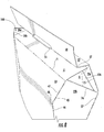
- Fig. 1 is a plan view of an interior surface 1 of a carton blank 3 for forming a reinforcing carton 5 ( Fig. 5 ) for holding a bag 6 or liner in a reinforced package 200 ( Fig. 14 ), according to an embodiment of the disclosure.
- the carton blank 3 has a lateral axis L1 and a longitudinal axis L2.
- the carton blank 3 has a front panel 21 foldably connected to a first side panel 28 at a first fold line 33, a back panel 23 foldably connected to the first side panel 28 at a second fold line 37, and a second side panel 29 foldably connected to the front panel 21 at a third fold line 40.
- an attachment flap 25 is foldably connected to the second side panel 29 at a fourth fold line 43.
- the first side panel 28 includes two individual panel portions 28a, 28b foldably connected to one another along a lateral fold line 26.
- the second side panel 29 includes two individual panel portions 29a, 29b foldably connected to one another along a lateral fold line 27.
- the first fold line 33 is segmented into two oblique fold line segments 34, 35 extending from a vertex 30a.
- the second fold line 37 is segmented into two oblique fold line segments 38, 39 extending from a vertex 30b.
- the third fold line 40 is segmented into two oblique fold line segments 41, 42 extending from a vertex 31a.
- the fourth fold line 43 is segmented into two oblique fold line segments 44, 45 extending from a vertex 31b.
- the fold lines 33, 37 can be spaced apart from lateral fold line 26 so that the vertices 30a, 30b are spaced apart from the lateral fold line 26 farther than the opposite ends of the oblique fold line segments 34, 35, 38, 39 (e.g., the panel portions 28a, 28b and the first side panel 28 are widest between or adjacent the vertices 30a, 30b).
- the fold lines 40, 43 are spaced apart from lateral fold line 27 so that the vertices 31a, 31b are spaced apart from the lateral fold line 27 farther than the opposite ends of the oblique fold line segments 41, 42, 44, 48 (e.g., the panel portions 29a, 29b and the first side panel 29 are widest between or adjacent the vertices 31a, 31b).
- the fold lines 33, 37, 40, 43 could be omitted or could be otherwise arranged, shaped, positioned, and/or configured without departing from the disclosure.
- the fold lines could be arcuate fold lines rather than segmented fold lines as shown.
- the blank 3 further includes a first bottom panel 51 foldably connected to the back panel 23 at longitudinal fold line 71 and a second bottom panel 52 foldably connected to the front panel 21 at longitudinal fold line 72.
- a bottom end flap 53 is foldably connected to the second bottom panel 52 at fold lines 57.
- a locking tab 55 extends from the second bottom panel 52 and is separable from the bottom end flap 53 along a cut 58.
- a complementary locking notch or recess 54 is formed in the first bottom panel 51 and defines an edge of the first bottom panel 51 for engaging the locking tab 55.
- the locking notch 54 is sized or dimensioned to engage the locking tab 55.
- the blank 3 includes adhesive regions 60 on the back panel 23, and front panel 21, for receiving adhesive and being fixedly attached to an exterior surface of the bag 6. Additionally, the blank 3 can include an adhesive region 61 on the attachment flap 25 for receiving adhesive and being fixedly attached to an interior surface of the back panel 23.
- the adhesive regions 60, 61 could be omitted or could be otherwise arranged, shaped, positioned, and/or configured without departing from the disclosure.
- the carton blank 3 has a first edge 70 (e.g. free edge) generally extending in the longitudinal direction L2.
- the blank 3 further includes oblique edges 73, 74, 75, and 76 (e.g. free edges) arranged opposite the first edge 70. Accordingly, the edges 73, 74, 75, 76 form lower free edges of the respective panel portions 28b, 28a, 29a, 29b.
- the edges 70, 73, 74, 75, 76 could be omitted or could be otherwise arranged, shaped, positioned, and/or configured without departing from the disclosure.
- the carton blank 3 and carton 5 can comprise any material which is relatively rigid such as paperboard, clay-coated paperboard, solid bleached board (SBB) paperboard, solid bleached sulphate (SBS) paperboard, Kraft line paperboard, or any other suitable material without departing from the disclosure.
- the carton blank 3 could be otherwise shaped and could have alternative panel, flap, fold line, and/or panel portion arrangements.
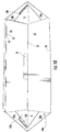
- a plan view of an interior surface 101 of an insert blank 103 or portion of liner material for forming a bag 6 ( Fig. 6 ) of the reinforced package 200 ( Fig. 12 ) is illustrated.
- the lateral axis L I and the longitudinal axis L2 of the liner blank 103 are oriented so that the lateral axis LI and the longitudinal axis L2 of the liner blank 103 comport with the respective lateral axis LI and longitudinal axis L2 of the carton blank 3 established in Fig. 1 .
- the liner blank 103 or liner material may be formed of generally non-permeable material or layers of material, such that a formed bag 6 may hold liquid.
- the liner blank 103 can comprise any suitable material which is relatively flexible and relatively fluid impervious.
- the liner blank 103 can comprise plastics such as polyethylene, polypropylene, polyethylene terephthalate, polystyrene, poly vinyl chloride, or any other suitable material without departing from the disclosure.
- the liner blank 103 could comprise a fluid pervious material without departing from the disclosure.
- the liner blank 103 may include sidewalls 105, 106 foldably connected to gusset panels 107, 108 at fold lines 109, 110, respectively.
- the gusset panels 107, 108 may be foldably connected to one another at fold line 113.
- the liner blank 103 may include glue areas 115, 116 extending along respective marginal areas of the blank and at least partially defined between a respective laterally-extending edge 117, 118 and a respective line 119, 120.
- the lines 119, 120 only schematically indicate the inner periphery of the glue areas 115, 116.
- the lines 119, 120 are drawn on and/or formed in the liner blank 103.
- guide lines may be drawn on the liner blank 103 and/or creases may be formed in the liner blank 103.
- Each of the glue areas 115, 116 can include sealing regions 121, 122 at opposite ends of the respective sidewalls 105, 106 along lateral portions of the lines 119, 120 and sealing corner portions 123, 124 at opposite ends of the respective sidewalls 105, 106 adjacent oblique portions of the respective lines 119, 120 and adjacent the respective fold lines 109, 110.
- the glue areas 115, 116 can include respective sealing corner portions 125 at opposite ends of the gusset panel 107 between fold lines 109, 113 and adjacent an oblique portion of the respective lines 119, 120 and respective sealing corner portions 127 at opposite ends of the gusset panel 108 between fold lines 110, 113 and adjacent an oblique portion of the respective lines 119, 120.
- the sidewalls 105, 106, the gusset panels 107, 108, and/or the glue areas 115, 116 could be omitted or could be otherwise arranged, shaped, positioned, or configured without departing from the disclosure.
- the bag 6 can be formed, in one exemplary embodiment, as shown in Fig. 3 . Accordingly, the liner blank 103 can be folded along the fold lines 113, 109, 110 so that the gusset panels 107, 108 are at least partially in face-to-face contact with one another and with the respective sidewalls 105, 106. Additionally, the sidewalls 105, 106 are disposed at least partially in face-to-face contact with one another above the gusset panels 107, 108. Glue can be applied to at least a portion of each of the glue areas 115, 116 (e.g., the shaded regions in Fig.
- each of the sealing corner portions 123 of the sidewall 105 is glued to the respective sealing corner portions 125 of the gusset panel 107 and each of the sealing corner portions 124 of the sidewall 106 is glued to the respective sealing corner portion 127 of the gusset panel 108 to form two sealed corners 132 at the bottom ends of each of the seams 130.
- the bag 6 could be formed from the liner blank 103 by alternative steps without departing from the disclosure.
- the portions of the sidewalls 105, 106 and the gusset panels 107, 108 outside the glue areas 115, 116 remain generally free of glue so that the sidewalls and gusset panels generally are not glued together outside the glue areas. Accordingly, the bag 6 can be expanded to open up an interior space of the bag by moving the sidewalls 105, 106 apart from one another and by folding the gusset panels 107, 108 along fold lines 109, 110, 113 so that the gusset panels 107, 108 are generally coplanar and extend between the spaced-apart sidewalls 105, 106.
- the seams 130 and the sealed corners 132 can form closed ends or sides of the bag 6, and the gusset panels 107, 108 and the sealed corners 132 can form a closed bottom 136 of the bag 6 while the bag is in either the collapsed configuration (e.g., Fig. 3 ) or the opened configuration (e.g., Fig. 17 ).
- the bag 6 can be positioned from the opened configuration to the closed configuration by folding the gusset panels 107, 108 inwardly along the fold lines 109, 110, 113 so that the fold line 113 and the gusset panels 107, 108 are disposed between the sidewalls 105, 106.
- the bag 6 could be positioned or moved between the collapsed configuration and the opened configuration by alternative steps without departing from the disclosure.
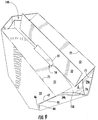
- the carton blank 3 may be folded about fold lines 26, 27 to form an open-ended sleeve 134 (e.g., a reinforcing sleeve formation).
- the bag 6 can be aligned with the carton blank 3 ( Fig. 4 ) and distal oblique edges 46, 47 of the back panel 23 may be overlapped and/or brought into registration with fold line segments 44, 45 ( Fig. 5 ) such that the back panel 23 at least partially overlaps the attachment flap 25 and adhesive region 61 to form the open-ended sleeve 134 ( Figs. 5 and 6 ).
- the back panel 23 can be glued to the attachment flap 25 by the adhesive region 61.
- the reinforcing sleeve 134 can be attached (e.g., glued) to the bag 6 through adhesive regions 60.
- the sidewalls 105, 106 can be glued to the respective front panel 21 and back panel 23 at adhesive regions 60.
- the seams 130 and the outer portions of the sealed corners 132 of the bag 6 may be folded to rest against the sidewall 106 as illustrated in Fig. 5 .
- the seams 130 and the outer portions of the sealed corners 132 of the bag 6 may be folded to rest against the sidewall 105.
- the bag 6 could be otherwise attached to the carton blank 3/carton 5 without departing from the disclosure.
- the either of the sidewalls 105, 106 could be glued to either of the front panel 21 and/or back panel 23 prior to folding the carton blank 3 or during or after formation of the carton 5.
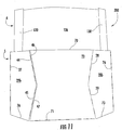
- bottom panel 51 may be folded inwardly against the bag 6 as illustrated in Fig. 7 . Thereafter, bottom panel 52 and bottom end flap 53 may be folded inwardly against the bottom panel 51 such that the locking tab 55 is brought into locking engagement with the locking notch 54, as illustrated in Figs. 8-10 .
- the bottom end flap 53 may receive adhesive and can be fixedly attached to the bottom panel 51. Alternatively, the bottom end flap 53 can remain free from attachment to the bottom panel 51.
- the folding sequences described above may be altered or omitted in some embodiments, without departing from the scope of the disclosure.
- a reinforcing carton 5 exists about the bag 6 forming a reinforced package 200.
- the bag 6 is glued to an interior surface of the front panel 21 and/or the back panel 23 in an interior 148 of the carton 5. Accordingly, the closed bottom 136 of the bag 6 can be disposed in the interior 148 of the carton 5.
- the package 200 can be in a first, non-erected position or configuration ( Figs. 11-13 ) or in a second, erected position or configuration ( Figs. 17-20 ).
- the individual panel portions 28a, 28b, 29a, and 29b are folded along the respective lateral fold lines 26, 27 so that the panel portions 28a, 29a generally oppose the respective panel portions 28b, 29b.
- the first, non-erect position illustrated reduces and/or minimizes (e.g., collapses) a volume of an interior space 150 of the bag 6 such that the reinforced package is in a non-erect or semi-flattened state ( Fig. 12A and 13 ).
- the carton 5 and bag 6 could be fully or substantially fully flattened in one embodiment.
- the non-erect state may facilitate easy stacking of a plurality of packages into, for example, a shipment container and subsequent organization at a destination facility. However, as illustrated in Fig. 13 , the non-erect state may still facilitate the filling of the interior volume 150 at least partially with a product. Thereafter, the interior volume 150 may be sealed in any feasible manner in one embodiment.
- the individual panel portions 28a, 28b, 29a, and 29b may be flexed or positioned to form first and second sides 28, 29 of the package in a second, erect position of the package as illustrated in Figs. 14-17 .
- the side panels 28, 29 are pushed inwardly at the respective fold lines 26, 27.
- the side panel 28 can be folded along fold lines 26, 33, 37 until the panel portions 28a, 28b are generally coplanar, extending between the front panel 21 and the back panel 23.
- the side panel 29 can be folded along fold lines 27, 40, 43 until the panel portions 29a, 29b are generally coplanar, extending between the front panel 21 and the attachment flap 25 and the back panel 23.
- the bottom panels 51, 52 can fold along fold lines 71, 72 to be generally coplanar, extending between the front panel and the back panel to form a closed bottom of the carton 5.
- the sidewalls 105, 106 of the bag 6 are glued to the respective front panel 21 and back panel 23, and the bag can be positioned in the open position by the front and back panels as the side panels 28, 29 are moved inwardly.
- the side panels 28, 29 are widest between the vertices 30a, 30b and 31a, 31b, when the package 200 is in the second, erected position, the side panels 28, 29 can push against the front panel 21 and the back panel 23 at the vertices 30a, 30b and 31a, 31b. This can create tension that can help retain the panel portions 28a, 28b and 29a, 29b in the generally coplanar position (e.g., can help resist folding of the side panels 28, 29).
- the oblique fold line segments 34, 35, 38, 39 and 41, 42, 44, 48 further can help resist folding of the side panels 28, 29.
- the side panels 28, 29 can be generally concave from the exterior of the carton 5 because of the oblique fold line segments of the fold lines 33, 37, 40, 43.
- the oblique fold line segments 34, 35, 38, 39, 41, 42, 44, 48, the vertices 30a, 30b, 31a, 31b and the panel portions 28a, 28b, 29a, 29b can cooperate with one another and with the interlocked bottom panels 51, 52 (including the locking tab 55) to form locking features that can help retain the package 200 in the erected configuration.
- the locking features can be at least partially disengaged, by pushing outwardly on one or both of the fold lines 26, 27 and moving the front panel 21 and the back panel 23 toward one another.
- the package 200 can be reconfigured between the non-erected and erected positions using alternative steps and/or features without departing from the disclosure.
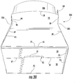
- the second, erect position, illustrated in Fig. 17 increases and/or maximizes a volume of the interior space 150 such that the package 200 is in an erect or self-supporting state.
- Bottom edges 71, 72, 73, 74, 75, 76 can cooperate to form a support when the package 200 is in the erect state for contacting a surface S (e.g., Fig. 17 ).
- the support formed of the bottom edges 71, 72 73, 74, 75, 76 (e.g., in a locking interaction due to side panels 28, 29) maintains the package in an upright position on the surface S.
- a user may fill the interior volume 150 at least partially with a liquid (e.g., water, heated water, etc.) for rehydrating a product within the volume 150.
- a liquid e.g., water, heated water, etc.
- the entire package 200 may be heated in a microwave oven to facilitate cooking and/or rehydrating of the contents of the bag 6.
- Other intervening states of the package 200 including intermediate states whereby the package is not fully erected are also applicable according to some embodiments.
- automatically erecting reinforced packages 200 are also applicable, for example, if bag 6 is filled with an expanding food product such as popcorn that expands when heated to move the front panel 21 and the back panel 23 apart to at least partially form side panels 28, 29 during the cooking process.
- bags can be formed from a bag stock material, although various plastic or other bag materials also can be used, and can be lined or coated with a desired material.
- the reinforcing cartons described herein can be made from a more rigid material such as a clay-coated natural kraft ("CCNK").
- CCNK clay-coated natural kraft
- Other materials such various card-stock, paper, plastic or other synthetic or natural materials also can be used to form the components of the packages described herein.
- the blank according to the present disclosure can be, for example, formed from coated paperboard and similar materials.
- the interior and/or exterior sides of the blank can be coated with a clay coating.
- the clay coating may then be printed over with product, advertising, price coding, and other information or images.
- the blank may then be coated with a varnish to protect any information printed on the blank.
- the blank may also be coated with, for example, a moisture barrier layer, on either or both sides of the blank.
- the blank may be constructed of paperboard of a caliper such that it is heavier and more rigid than ordinary paper.
- the blank can also be constructed of other materials, such as cardboard, hard paper, or any other material having properties suitable for enabling the carton to function at least generally as described above.
- the blank can also be laminated to or coated with one or more sheet-like materials at selected panels or panel sections.
- a fold line can be any substantially linear, although not necessarily straight, form of weakening that facilitates folding therealong. More specifically, but not for the purpose of narrowing the scope of the present disclosure, fold lines include: a score line, such as lines formed with a blunt scoring knife, or the like, which creates a crushed portion in the material along the desired line of weakness; a cut that extends partially into a material along the desired line of weakness, and/or a series of cuts that extend partially into and/or completely through the material along the desired line of weakness; and various combinations of these features. In situations where cutting is used to create a fold line, typically the cutting will not be overly extensive in a manner that might cause a reasonable user to incorrectly consider the fold line to be a tear line or other line of disruption.
- a tear line can include: a slit that extends partially into the material along the desired line of weakness, and/or a series of spaced apart slits that extend partially into and/or completely through the material along the desired line of weakness, or various combinations of these features.
- one type tear line is in the form of a series of spaced apart slits that extend completely through the material, with adjacent slits being spaced apart slightly so that a nick (e.g., a small somewhat bridging-like piece of the material) is defined between the adjacent slits for typically temporarily connecting the material across the tear line. The nicks are broken during tearing along the tear line.
- the nicks typically are a relatively small percentage of the tear line, and alternatively the nicks can be omitted from or torn in a tear line such that the tear line is a continuous cut line. That is, it is within the scope of the present disclosure for each of the tear lines to be replaced with a continuous slit, or the like.
- a cut line can be a continuous slit or could be wider than a slit without departing from the present disclosure.
- the above embodiments may be described as having one or more panels adhered together by glue during erection of the carton embodiments.
- glue is intended to encompass all manner of adhesives commonly used to secure carton panels in place.
Landscapes
- Engineering & Computer Science (AREA)
- Mechanical Engineering (AREA)
- Packages (AREA)
- Cartons (AREA)
- Bag Frames (AREA)
- Package Specialized In Special Use (AREA)
Description
- The present disclosure generally relates to packages for holding products. More specifically, the present disclosure is directed to packages of the generic type as defined in the preamble of claim 1 having a reinforcing carton supporting a bag.
- A package of the generic type is disclosed in
US 2004/0004111 A1 . The two bottom panels foldably connected to the front and the back panel are interconnected by a bottom panel extension provided at one of the bottom panels and partially overlapping the other bottom panel and being adhered to the latter. In the collapsed configuration of the package, the said bottom panels are co-planar with the respective front and back panel to which they are foldably connected, the bottom panel extension being folded at a bottom flap fold line. -
EP 2492203 A1 discloses a combination package comprising a tube-like body and a product bag received therein. The tube-like body, which may be formed from a flat material, is essentially form-stable in its erected use-configuration. A specific fold line pattern defining triangles allows for collapsing the body into a flattened non-use configuration. - The present invention aims at providing for an improved package of the generic type.
- The above object is achieved by the package of claim 1 and by the package forming method of claim 11, respectively.
- In one aspect, the present disclosure is generally directed to a reinforced package for holding a product. The reinforced package comprises a carton comprising a plurality of panels that extend at least partially around an interior of the carton. The plurality of panels comprises a front panel, a first side panel foldably connected to the front panel, a second side panel foldably connected to the front panel, a back panel foldably connected to at least one of the first side panel and the second side panel, and two bottom panels foldably connected to the front panel and the back panel, respectively. A bag comprises an at least partially open end, a closed end, and an interior space for holding a product. The bag is at least partially received in the interior of the carton. The carton is positionable in a non-erect position wherein the interior space of the bag is at least partially collapsed and in an erect position wherein the interior space of the bag is increased. The carton is configured to support the bag in the erect position. The bottom structure is defined in detail in claim 1.
- In another aspect, the disclosure is generally directed to a method for forming a reinforced package for holding a product. The method comprises obtaining a carton blank comprising a plurality of panels comprising a front panel, a first side panel foldably connected to the front panel, a second side panel foldably connected to the front panel, a back panel foldably connected to at least one of the first side panel and the second side panel, and two bottom panels foldably connected to the front panel and the back panel. The method also comprises obtaining a liner blank, forming a bag from the liner blank so that the bag comprises an at least partially open end, a closed end, and an interior space for holding a product, attaching at least a portion of the bag to at least one of the front panel and the back panel of the carton blank, and fonning an interior of a carton at least partially defined by the plurality of panels. The forming the interior of the carton comprises forming an open-ended sleeve. The carton is positionable in a non-erect position wherein the interior space of the bag is at least partially collapsed and in an erect position wherein the interior space of the bag is increased. The carton is configured to support the bag in the erect position. The bottom structure is defined in detail in claim 11.
- Those skilled in the art will appreciate the above stated advantages and other advantages and benefits of various additional embodiments reading the following detailed description of the embodiments with reference to the below-listed drawing figures. It is within the scope of the present disclosure that the above-discussed aspects be provided both individually and in various combinations.
- According to common practice, the various features of the drawings discussed below are not necessarily drawn to scale. Dimensions of various features and elements in the drawings may be expanded or reduced to more clearly illustrate the embodiments of the disclosure.
-
Fig. 1 is a plan view of an interior surface of a carton blank for forming a reinforcing carton of a reinforced package according to an exemplary embodiment of the disclosure. -
Fig. 2 is a plan view of an interior surface of a liner blank for forming a bag of the reinforced package according to the exemplary embodiment of the disclosure. -
Fig. 3 is a front view of the bag formed from the liner blank ofFig. 2 . -
Fig. 4 is a plan view of the bag ofFig. 3 positioned relative to the blank ofFig. 1 . -
Figs. 5 and6 are views showing a partially-formed carton with the bag received therein according to the exemplary embodiment of the disclosure. -
Figs. 7-10 are bottom perspective views of the partially-formed carton ofFigs. 5 and6 showing the formation of a closed bottom of the carton according to the exemplary embodiment of the disclosure. -
Fig. 11 is a front view of the reinforced package in a non-erected position according to the exemplary embodiment of the disclosure. -
Figs. 12A and 12B are bottom views of the reinforced package in the non-erected position according to the exemplary embodiment of the disclosure. -
Fig. 13 is a top view of the reinforced package in the non-erected position according to the exemplary embodiment of the disclosure. -
Figs 14-16 illustrate a transition of the reinforced package from the non-erected position to an erected position according to the exemplary embodiment of the disclosure. -
Fig. 17 is a perspective view of the reinforced package in the erected position according to the exemplary embodiment of the disclosure. -
Fig. 18 is a top view of the reinforced package in the erected position according to the exemplary embodiment of the disclosure. -
Figs. 19 and20 are bottom perspective views of the reinforced package in the erected position according to the exemplary embodiment of the disclosure. - Corresponding parts are designated by corresponding reference numbers throughout the drawings.
- The present disclosure generally relates to cartons and packages for holding products or articles such as food products or other articles. Packages according to the present disclosure can accommodate articles of any shape. For purpose of illustration and not for the purpose of limiting the scope of the disclosure, the terms "lower", "bottom", "upper", "top", "front", and "back" indicate orientations determined in relation to erected cartons.
-
Fig. 1 is a plan view of an interior surface 1 of a carton blank 3 for forming a reinforcing carton 5 (Fig. 5 ) for holding abag 6 or liner in a reinforced package 200 (Fig. 14 ), according to an embodiment of the disclosure. The carton blank 3 has a lateral axis L1 and a longitudinal axis L2. In the illustrated embodiment, the carton blank 3 has afront panel 21 foldably connected to afirst side panel 28 at afirst fold line 33, aback panel 23 foldably connected to thefirst side panel 28 at asecond fold line 37, and asecond side panel 29 foldably connected to thefront panel 21 at athird fold line 40. As shown inFig. 1 , anattachment flap 25 is foldably connected to thesecond side panel 29 at afourth fold line 43. - As shown in
Fig. 1 , thefirst side panel 28 includes twoindividual panel portions lateral fold line 26. Similarly, thesecond side panel 29 includes twoindividual panel portions lateral fold line 27. - In the illustrated embodiment, the
first fold line 33 is segmented into two obliquefold line segments vertex 30a. Thesecond fold line 37 is segmented into two obliquefold line segments vertex 30b. Thethird fold line 40 is segmented into two obliquefold line segments vertex 31a. Thefourth fold line 43 is segmented into two obliquefold line segments vertex 31b. Thefold lines lateral fold line 26 so that thevertices lateral fold line 26 farther than the opposite ends of the obliquefold line segments panel portions first side panel 28 are widest between or adjacent thevertices fold lines lateral fold line 27 so that thevertices lateral fold line 27 farther than the opposite ends of the obliquefold line segments panel portions first side panel 29 are widest between or adjacent thevertices fold lines - As shown in
Fig. 1 , the blank 3 further includes a firstbottom panel 51 foldably connected to theback panel 23 atlongitudinal fold line 71 and a secondbottom panel 52 foldably connected to thefront panel 21 atlongitudinal fold line 72. As illustrated, abottom end flap 53 is foldably connected to thesecond bottom panel 52 at fold lines 57. A lockingtab 55 extends from thesecond bottom panel 52 and is separable from thebottom end flap 53 along acut 58. Furthermore, a complementary locking notch orrecess 54 is formed in the firstbottom panel 51 and defines an edge of the firstbottom panel 51 for engaging thelocking tab 55. The lockingnotch 54 is sized or dimensioned to engage thelocking tab 55. - In the illustrated embodiment, the blank 3 includes
adhesive regions 60 on theback panel 23, andfront panel 21, for receiving adhesive and being fixedly attached to an exterior surface of thebag 6. Additionally, the blank 3 can include anadhesive region 61 on theattachment flap 25 for receiving adhesive and being fixedly attached to an interior surface of theback panel 23. Theadhesive regions - As shown in
Fig. 1 , the carton blank 3 has a first edge 70 (e.g. free edge) generally extending in the longitudinal direction L2. The blank 3 further includes oblique edges 73, 74, 75, and 76 (e.g. free edges) arranged opposite thefirst edge 70. Accordingly, theedges respective panel portions edges - In the illustrated embodiment, the carton blank 3 and
carton 5 can comprise any material which is relatively rigid such as paperboard, clay-coated paperboard, solid bleached board (SBB) paperboard, solid bleached sulphate (SBS) paperboard, Kraft line paperboard, or any other suitable material without departing from the disclosure. In alternative embodiments, the carton blank 3 could be otherwise shaped and could have alternative panel, flap, fold line, and/or panel portion arrangements. - Turning to
Fig. 2 , a plan view of aninterior surface 101 of an insert blank 103 or portion of liner material for forming a bag 6 (Fig. 6 ) of the reinforced package 200 (Fig. 12 ) is illustrated. As illustrated inFig. 2 , the lateral axis L I and the longitudinal axis L2 of the liner blank 103 are oriented so that the lateral axis LI and the longitudinal axis L2 of the liner blank 103 comport with the respective lateral axis LI and longitudinal axis L2 of the carton blank 3 established inFig. 1 . The liner blank 103 or liner material may be formed of generally non-permeable material or layers of material, such that a formedbag 6 may hold liquid. The liner blank 103 can comprise any suitable material which is relatively flexible and relatively fluid impervious. The liner blank 103 can comprise plastics such as polyethylene, polypropylene, polyethylene terephthalate, polystyrene, poly vinyl
chloride, or any other suitable material without departing from the disclosure. Alternatively, the liner blank 103 could comprise a fluid pervious material without departing from the disclosure. - As shown in
Fig. 2 , the liner blank 103 may includesidewalls gusset panels fold lines gusset panels fold line 113. The liner blank 103 may includeglue areas edge respective line lines glue areas lines liner blank 103. For example, guide lines may be drawn on the liner blank 103 and/or creases may be formed in theliner blank 103. Each of theglue areas regions respective sidewalls lines corner portions respective sidewalls respective lines respective fold lines glue areas sealing corner portions 125 at opposite ends of thegusset panel 107 betweenfold lines respective lines sealing corner portions 127 at opposite ends of thegusset panel 108 betweenfold lines respective lines sidewalls gusset panels glue areas - The
bag 6 can be formed, in one exemplary embodiment, as shown inFig. 3 . Accordingly, the liner blank 103 can be folded along thefold lines gusset panels respective sidewalls sidewalls gusset panels glue areas 115, 116 (e.g., the shaded regions inFig. 3 ) on theinterior surface 101 of the liner blank 103 before, after, and/or during folding along thefold lines regions 121 of thesidewall 105 are disposed in face-to-face contact with therespective sealing regions 122 of thesidewall 106, the sealing regions are glued together to at least partially form aseam 130 at each end of the bag 6 (Fig. 3 ). Additionally, each of the sealingcorner portions 123 of thesidewall 105 is glued to the respectivesealing corner portions 125 of thegusset panel 107 and each of the sealingcorner portions 124 of thesidewall 106 is glued to the respectivesealing corner portion 127 of thegusset panel 108 to form two sealedcorners 132 at the bottom ends of each of theseams 130. Thebag 6 could be formed from the liner blank 103 by alternative steps without departing from the disclosure. - In one embodiment, the portions of the
sidewalls gusset panels glue areas bag 6 can be expanded to open up an interior space of the bag by moving thesidewalls gusset panels fold lines gusset panels sidewalls seams 130 and the sealedcorners 132 can form closed ends or sides of thebag 6, and thegusset panels corners 132 can form aclosed bottom 136 of thebag 6 while the bag is in either the collapsed configuration (e.g.,Fig. 3 ) or the opened configuration (e.g.,Fig. 17 ). Thebag 6 can be positioned from the opened configuration to the closed configuration by folding thegusset panels fold lines fold line 113 and thegusset panels sidewalls bag 6 could be positioned or moved between the collapsed configuration and the opened configuration by alternative steps without departing from the disclosure. - Generally, the carton blank 3 may be folded about
fold lines Figs. 4-6 , thebag 6 can be aligned with the carton blank 3 (Fig. 4 ) and distal oblique edges 46, 47 of theback panel 23 may be overlapped and/or brought into registration withfold line segments 44, 45 (Fig. 5 ) such that theback panel 23 at least partially overlaps theattachment flap 25 andadhesive region 61 to form the open-ended sleeve 134 (Figs. 5 and6 ). Accordingly, theback panel 23 can be glued to theattachment flap 25 by theadhesive region 61. During this sequence, the reinforcingsleeve 134 can be attached (e.g., glued) to thebag 6 throughadhesive regions 60. For example, thesidewalls front panel 21 and backpanel 23 atadhesive regions 60. Further, theseams 130 and the outer portions of the sealedcorners 132 of thebag 6 may be folded to rest against thesidewall 106 as illustrated inFig. 5 . Alternatively, theseams 130 and the outer portions of the sealedcorners 132 of thebag 6 may be folded to rest against thesidewall 105. Thebag 6 could be otherwise attached to the carton blank 3/carton 5 without departing from the disclosure. For example, the either of thesidewalls front panel 21 and/orback panel 23 prior to folding the carton blank 3 or during or after formation of thecarton 5. - Upon attachment of the reinforcing
sleeve 134 to thebag 6,bottom panel 51 may be folded inwardly against thebag 6 as illustrated inFig. 7 . Thereafter,bottom panel 52 andbottom end flap 53 may be folded inwardly against thebottom panel 51 such that thelocking tab 55 is brought into locking engagement with the lockingnotch 54, as illustrated inFigs. 8-10 . According to some embodiments, thebottom end flap 53 may receive adhesive and can be fixedly attached to thebottom panel 51. Alternatively, thebottom end flap 53 can remain free from attachment to thebottom panel 51. Furthermore, the folding sequences described above may be altered or omitted in some embodiments, without departing from the scope of the disclosure. - Upon folding the
bottom panels bottom end flap 53, a reinforcingcarton 5 exists about thebag 6 forming a reinforcedpackage 200. In one embodiment, thebag 6 is glued to an interior surface of thefront panel 21 and/or theback panel 23 in an interior 148 of thecarton 5. Accordingly, theclosed bottom 136 of thebag 6 can be disposed in theinterior 148 of thecarton 5. In the illustrated embodiment, thepackage 200 can be in a first, non-erected position or configuration (Figs. 11-13 ) or in a second, erected position or configuration (Figs. 17-20 ). In the first position, theindividual panel portions lateral fold lines panel portions respective panel portions interior space 150 of thebag 6 such that the reinforced package is in a non-erect or semi-flattened state (Fig. 12A and13 ). As shown inFig. 12B , thecarton 5 andbag 6 could be fully or substantially fully flattened in one embodiment. The non-erect state may facilitate easy stacking of a plurality of packages into, for example, a shipment container and subsequent organization at a destination facility. However, as illustrated inFig. 13 , the non-erect state may still facilitate the filling of theinterior volume 150 at least partially with a product. Thereafter, theinterior volume 150 may be sealed in any feasible manner in one embodiment. - Upon receipt of a reinforced
package 200 in the first, non-erect position (with or without a sealed interior volume 150), theindividual panel portions second sides Figs. 14-17 . Accordingly, in one embodiment, theside panels respective fold lines side panel 28 can be folded alongfold lines panel portions front panel 21 and theback panel 23. Similarly, and, in one embodiment, at the same time, theside panel 29 can be folded alongfold lines panel portions front panel 21 and theattachment flap 25 and theback panel 23. Additionally, as thefront panel 21 and theback panel 23 move away from one another, thebottom panels fold lines carton 5. Further, thesidewalls bag 6 are glued to the respectivefront panel 21 and backpanel 23, and the bag can be positioned in the open position by the front and back panels as theside panels - In one embodiment, since the
side panels vertices package 200 is in the second, erected position, theside panels front panel 21 and theback panel 23 at thevertices panel portions side panels 28, 29). Additionally, since thefront panel 21 and theback panel 23 are widest at theedge 70 and at the lower edges (e.g., foldlines 71, 72), the obliquefold line segments side panels side panels carton 5 because of the oblique fold line segments of the fold lines 33, 37, 40, 43. Accordingly, the obliquefold line segments vertices panel portions bottom panels 51, 52 (including the locking tab 55) to form locking features that can help retain thepackage 200 in the erected configuration. In one embodiment, for example, the locking features can be at least partially disengaged, by pushing outwardly on one or both of the fold lines 26, 27 and moving thefront panel 21 and theback panel 23 toward one another. Thepackage 200 can be reconfigured between the non-erected and erected positions using alternative steps and/or features without departing from the disclosure. - The second, erect position, illustrated in
Fig. 17 , increases and/or maximizes a volume of theinterior space 150 such that thepackage 200 is in an erect or self-supporting state. Bottom edges 71, 72, 73, 74, 75, 76 can cooperate to form a support when thepackage 200 is in the erect state for contacting a surface S (e.g.,Fig. 17 ). The support formed of thebottom edges side panels 28, 29) maintains the package in an upright position on the surface S. Furthermore, due to the impermeable nature of thebag 6, a user may fill theinterior volume 150 at least partially with a liquid (e.g., water, heated water, etc.) for rehydrating a product within thevolume 150. Moreover, according to some embodiments, the entire package 200 (filled with liquid or not) may be heated in a microwave oven to facilitate cooking and/or rehydrating of the contents of thebag 6. Other intervening states of thepackage 200 including intermediate states whereby the package is not fully erected are also applicable according to some embodiments. Furthermore, automatically erecting reinforcedpackages 200 are also applicable, for example, ifbag 6 is filled with an expanding food product such as popcorn that expands when heated to move thefront panel 21 and theback panel 23 apart to at least partially formside panels - Generally, as described herein, bags can be formed from a bag stock material, although various plastic or other bag materials also can be used, and can be lined or coated with a desired material. The reinforcing cartons described herein can be made from a more rigid material such as a clay-coated natural kraft ("CCNK"). Other materials such various card-stock, paper, plastic or other synthetic or natural materials also can be used to form the components of the packages described herein.
- The blank according to the present disclosure can be, for example, formed from coated paperboard and similar materials. For example, the interior and/or exterior sides of the blank can be coated with a clay coating. The clay coating may then be printed over with product, advertising, price coding, and other information or images. The blank may then be coated with a varnish to protect any information printed on the blank. The blank may also be coated with, for example, a moisture barrier layer, on either or both sides of the blank. In accordance with the above-described embodiments, the blank may be constructed of paperboard of a caliper such that it is heavier and more rigid than ordinary paper. The blank can also be constructed of other materials, such as cardboard, hard paper, or any other material having properties suitable for enabling the carton to function at least generally as described above. The blank can also be laminated to or coated with one or more sheet-like materials at selected panels or panel sections.
- In accordance with the above-described embodiments of the present disclosure, a fold line can be any substantially linear, although not necessarily straight, form of weakening that facilitates folding therealong. More specifically, but not for the purpose of narrowing the scope of the present disclosure, fold lines include: a score line, such as lines formed with a blunt scoring knife, or the like, which creates a crushed portion in the material along the desired line of weakness; a cut that extends partially into a material along the desired line of weakness, and/or a series of cuts that extend partially into and/or completely through the material along the desired line of weakness; and various combinations of these features. In situations where cutting is used to create a fold line, typically the cutting will not be overly extensive in a manner that might cause a reasonable user to incorrectly consider the fold line to be a tear line or other line of disruption.
- As an example, a tear line can include: a slit that extends partially into the material along the desired line of weakness, and/or a series of spaced apart slits that extend partially into and/or completely through the material along the desired line of weakness, or various combinations of these features. As a more specific example, one type tear line is in the form of a series of spaced apart slits that extend completely through the material, with adjacent slits being spaced apart slightly so that a nick (e.g., a small somewhat bridging-like piece of the material) is defined between the adjacent slits for typically temporarily connecting the material across the tear line. The nicks are broken during tearing along the tear line. The nicks typically are a relatively small percentage of the tear line, and alternatively the nicks can be omitted from or torn in a tear line such that the tear line is a continuous cut line. That is, it is within the scope of the present disclosure for each of the tear lines to be replaced with a continuous slit, or the like. For example, a cut line can be a continuous slit or could be wider than a slit without departing from the present disclosure.
- The above embodiments may be described as having one or more panels adhered together by glue during erection of the carton embodiments. The term "glue" is intended to encompass all manner of adhesives commonly used to secure carton panels in place.
- The foregoing description of the disclosure illustrates and describes various embodiments of the present disclosure. As various changes could be made in the above construction without departing from the scope of the disclosure, it is intended that all matter contained in the above description or shown in the accompanying drawings shall be interpreted as illustrative and not in a limiting sense. Furthermore, the scope of the present disclosure covers various modifications, combinations, alterations, etc., of the above-described embodiments that are within the scope of the claims. Additionally, the disclosure shows and describes only selected embodiments of the disclosure, but the disclosure is capable of use in various other combinations, modifications, and environments and is capable of changes or modifications within the scope of the inventive concept as expressed herein, commensurate with the above teachings, and/or within the skill or knowledge of the relevant art. Furthermore, certain features and characteristics of each embodiment may be selectively interchanged and applied to other illustrated and non-illustrated embodiments of the disclosure without departing from the scope of the disclosure.
Claims (15)
- A reinforced package (200) for holding a product, the reinforced package (200) comprising:a carton (5) comprising a plurality of panels (21, 23, 28, 29, 51, 52) that extend at least partially around an interior (148) of the carton (5), the plurality of panels (21, 23, 28, 29, 51, 52) comprising a front panel (21), a first side panel (28) foldably connected to the front panel (21), a second side panel (29) foldably connected to the front panel (21), a back panel (23) foldably connected to the first side panel (28), and at least one bottom panel (51, 52) foldably connected to at least one of the front panel (21) and the back panel (23), the at least one bottom panel (51, 52) comprising a first bottom panel (51) foldably connected to the back panel (23) and a second bottom panel (52) foldably connected to the front panel (21);a bag (6) comprising an at least partially open end, a closed end (136), and an interior space (150) for holding a product, the bag (6) being at least partially received in the interior (148) of the carton (5);wherein the carton (5) is positionable in a non-erect position wherein the interior space (150) of the bag (6) is at least partially collapsed and in an erect position wherein the interior space (150) of the bag (6) is increased, and the carton (5) supports the bag (6) in the erect position, characterized by:a locking tab (55) extending from the second bottom panel (52) and engaging an edge (54) of the first bottom panel (51); anda bottom flap (53) foldably connected to the second bottom panel (52) along a fold line (57) that is at least partially interrupted by the locking tab (55), and the locking tab (55) is at least partially defined by a cut line (58) in the bottom flap (53).
- The reinforced package (200) of claim 1, wherein the closed end (136) of the bag (6) is at least partially received in the interior (148) of the carton (5).
- The reinforced package (200) of claim 1, wherein the bag (6) is at least partially glued to an interior surface (1) of at least one of the front panel (21) and the back panel (23), the bag (6) further comprises at least one sidewall (105, 106) that is glued to the interior surface (1) of the at least one of the front panel (21) and the back panel (23).
- The reinforced package (200) of claim 1, wherein the bag (6) comprises a first sidewall (105) and a second sidewall (106), each extending generally upwardly from the closed end (136) of the bag (6), the first sidewall (105) and the second sidewall (106) are attached to one another by at least one seam (130) extending along a marginal area of the bag (6).
- The reinforced package (200) of claim 4, wherein the at least one seam (130) comprises at least a first seam (130) and a second seam (130), the first seam (130) and the second seam (130) extending along respective marginal areas of the bag (6).
- The reinforced package (200) of claim 4, wherein the at least one seam (130) comprises at least one glue area (115, 116) extending along each of the first sidewall (105) and the second sidewall (106), and respective portions (121, 122) of the at least one glue area (115, 116) in the first sidewall (105) and the second sidewall (106) are at least partially glued in face-to-face contact, the at least one glue area (115, 116) further extends along at least a portion of the closed end (136) of the bag (6), at least a portion (123, 134, 125, 127) of the at least one glue area (115, 116) in the closed end (136) being at least partially glued to another portion (123, 134, 125, 127) of the at least one glue area (115, 116) in the closed end (136) to form at least one sealed corner (132) of the bag (6), the at least one seam (130) comprises at least a first seam (130) and a second seam (130), the at least one glue area (115, 116) comprises at least a first glue area (115) and a second glue area (116), and the at least one sealed corner (132) comprises a first sealed corner (132) and a second sealed corner (132).
- The reinforced package (200) of claim 1, wherein:the bag (6) comprises a first sidewall (105) and a second sidewall (106), each extending generally upwardly from the closed end (136) of the bag (6),the closed end (136) of the bag (6) comprises a first gusset panel (107) foldably connected to a second gusset panel (108) along a first fold line (113), the first sidewall (105) is foldably connected to the first gusset panel (107) along a second fold line (109), and the second sidewall (106) is foldably connected to the second gusset panel (108) along a third fold line (110);the first gusset panel (107) and the second gusset panel (108) are generally coplanar with each other when the carton (5) is in the erect position and are at least partially folded with respect to one another along the first fold line (113) when the carton (5) is in the non-erect position, andthe first gusset panel (107) and the second gusset panel (108) are disposed generally between the first sidewall (105) and the second sidewall (106) when the carton (5) is in the non-erect position.
- The reinforced package (200) of claim 1, wherein the first side panel (28) comprises a first panel portion (28a) foldably connected to a second panel portion (28b) along a first lateral fold line (26), and the second side panel (29) comprises a third panel portion (29a) foldably connected to a fourth panel portion (29b) along a second lateral fold line (27), the first panel portion (28a) and the third panel portion (29a) are generally coplanar with the respective second panel portion (28b) and fourth panel portion (29b) when the carton (5) is in the erect position, and the first side panel (28) and the second side panel (29) being folded along the respective first lateral fold line (26) and second lateral fold line (27) so that the first panel portion (28a) generally opposes the second panel portion (28b) and the third panel portion (29a) generally opposes the fourth panel portion (29b) when the carton (5) is in the non-erect position, the first side panel (28) is foldably connected to the front panel (21) along a first fold line (33) and to the back panel (23) along a second fold line (37), the second side panel (29) is foldably connected to the front panel (21) along a third fold line (40) and to an attachment flap (25) along a fourth fold line (43), the attachment flap (25) is at least partially attached to the back panel (23), and each of the first fold line (33), the second fold line (37), the third fold line (40), and the fourth fold line (43) comprises a first oblique portion (34, 38, 41, 44) extending from a second oblique portion (35, 39, 42, 48) so that each of the front panel (21) and the back panel (23) is widest at respective upper (70) and lower edges (73, 74, 75, 76).
- The reinforced package (200) of claim 1, wherein the first side panel (28) comprises a first panel portion (28a) foldably connected to a second panel portion (28b) along a first fold line (26), the first panel portion (28a) is foldably connected to the front panel (21) along a second fold line (33), and the second panel portion (28b) is foldably connected to the back panel (23) along a third fold line (37), each of the second fold line (33) and the third fold line (37) comprises a first oblique portion (34, 38) extending from a second oblique portion (35, 39) at a vertex (30b, 30a), each vertex (30b, 30a) being spaced apart from the first fold line (26) so that each of the first panel portion (28a) and the second panel portion (28b) is widest adjacent the respective vertex (30b, 30a).
- The reinforced package (200) of claim 1, wherein the bottom flap (53) is fixedly attached to the first bottom panel (51).
- A method for forming a reinforced package (200) for holding a product, the method comprising:obtaining a carton blank (3) comprising a plurality of panels (21, 23, 28, 29, 51, 52) comprising a front panel (21), a first side panel (28) foldably connected to the front panel (21), a second side panel (29) foldably connected to the front panel (21), a back panel (23) foldably connected to the first side panel (28), and at least one bottom panel (51, 52) foldably connected to at least one of the front panel (21) and the back panel (23), the at least one bottom panel (51, 52) comprising a first bottom panel (51) foldably connected to the back panel (23) and a second bottom panel (52) foldably connected to the front panel (21);obtaining a liner blank (103);forming a bag (6) from the liner blank (103) so that the bag (6) comprises an at least partially open end, a closed end (136), and an interior space (150) for holding a product;attaching at least a portion of the bag (6) to at least one of the front panel (21) and the back panel (23) of the carton blank (3); andforming an interior (148) of a carton (5) at least partially defined by the plurality of panels (21, 23, 28, 29, 51, 52), the forming the interior (148) of the carton (5) comprising forming an open-ended sleeve (134);wherein the carton (5) is positionable in a non-erect position wherein the interior space (150) of the bag (6) is at least partially collapsed and in an erect position wherein the interior space (150) of the bag (6) is increased, and the carton (5) supports the bag (6) in the erect position, characterized by:the blank further comprising a locking tab (55) extending from the second bottom panel (52) and a bottom flap (53) foldably connected to the second bottom panel (52) along a fold line (57) that is at least partially interrupted by the locking tab (55), the locking tab (55) being at least partially defined by a cut line (58) in the bottom flap (53); andthe forming the interior (148) of the carton (5) further comprising engaging the locking tab (55) with an edge (54) of the first bottom panel (51).
- The method of claim 11, wherein:the bag (6) comprises a first sidewall (105) and a second sidewall (106); andthe forming the bag (6) comprising attaching the first sidewall (105) to the second sidewall (106) at at least one seam (130) along a marginal area of the bag (6) so that each of the first sidewall (105) and the second sidewall (106) extends generally upwardly from the closed end (136) of the bag (6).
- The method of claim 12, wherein the at least one seam (130) comprises at least one glue area (115, 116) extending along each of the first sidewall (105) and the second sidewall (106), and the attaching the first sidewall (105) to the second sidewall (106) comprising gluing respective portions (121, 122) of the at least one glue area (115, 116) in the first sidewall (105) and the second sidewall (106) in face-to-face contact, the at least one glue area (115, 116) further extends along at least a portion of the closed end (136) of the bag (6), the gluing the respective portions of the at least one glue area (115, 116) comprising gluing at least a portion (123, 134, 125, 127) of the at least one glue area (115, 116) in the closed end (136) to another portion (123, 134, 125, 127) of the at least one glue area (115, 116) in the closed end (136) to form at least one sealed corner (132) of the bag (6).
- The method of claim 11, wherein:the first side panel (28) comprises a first panel portion (28a) foldably connected to a second panel portion (28b) along a first lateral fold line (26), and the second side panel (29) comprises a third panel portion (29a) foldably connected to a fourth panel portion (29b) along a second lateral fold line (27);the first side panel (28) is foldably connected to the front panel (21) along a first fold line (33) and to the back panel (23) along a second fold line (37), the second side panel (29) is foldably connected to the front panel (21) along a third fold line (40) and to an attachment flap (25) along a fourth fold line (43); andthe forming the interior (148) of the carton (5) comprising folding the first side panel (28) and the second side panel (29) along the respective first lateral fold line (26) and second lateral fold line (27) and at least partially overlapping the back panel (23) and the attachment flap (25).
- The method of claim 14, wherein each of the first fold line (33), the second fold line (37), the third fold line (40), and the fourth fold line (43) comprises a first oblique portion (34, 38, 41, 44) extending from a second oblique portion (35, 39, 42, 48) at a vertex (30b, 30a, 31a, 31b), each vertex (30b, 30a, 31a, 31b) being spaced apart from the respective first lateral fold line (26) and second lateral fold line (27) so that each of the first side panel (28) and the second side panel (29) is widest adjacent the respective vertices (30b, 30a, 31a, 31b).
Applications Claiming Priority (2)
| Application Number | Priority Date | Filing Date | Title |
|---|---|---|---|
| US201361960712P | 2013-09-25 | 2013-09-25 | |
| PCT/US2014/057385 WO2015048242A1 (en) | 2013-09-25 | 2014-09-25 | Reinforced package |
Publications (3)
| Publication Number | Publication Date |
|---|---|
| EP3049338A1 EP3049338A1 (en) | 2016-08-03 |
| EP3049338A4 EP3049338A4 (en) | 2017-07-05 |
| EP3049338B1 true EP3049338B1 (en) | 2018-12-26 |
Family
ID=52690090
Family Applications (1)
| Application Number | Title | Priority Date | Filing Date |
|---|---|---|---|
| EP14849557.5A Active EP3049338B1 (en) | 2013-09-25 | 2014-09-25 | Reinforced package |
Country Status (9)
| Country | Link |
|---|---|
| US (1) | US9758275B2 (en) |
| EP (1) | EP3049338B1 (en) |
| JP (1) | JP6426719B2 (en) |
| CN (1) | CN105555672B (en) |
| BR (1) | BR112016001763B1 (en) |
| CA (1) | CA2918510C (en) |
| ES (1) | ES2708382T3 (en) |
| MX (1) | MX2016003466A (en) |
| WO (1) | WO2015048242A1 (en) |
Families Citing this family (30)
| Publication number | Priority date | Publication date | Assignee | Title |
|---|---|---|---|---|
| GB201205243D0 (en) | 2012-03-26 | 2012-05-09 | Kraft Foods R & D Inc | Packaging and method of opening |
| GB2511559B (en) | 2013-03-07 | 2018-11-14 | Mondelez Uk R&D Ltd | Improved Packaging and Method of Forming Packaging |
| GB2511560B (en) | 2013-03-07 | 2018-11-14 | Mondelez Uk R&D Ltd | Improved Packaging and Method of Forming Packaging |
| CN105555672B (en) | 2013-09-25 | 2018-05-25 | 印刷包装国际有限责任公司 | Enhance package |
| US9771176B2 (en) | 2013-09-25 | 2017-09-26 | Graphic Packaging International, Inc. | Reinforced package |
| US9957080B2 (en) | 2013-09-25 | 2018-05-01 | Graphic Packaging International, Llc | Reinforced package |
| US10640271B2 (en) | 2015-04-29 | 2020-05-05 | Graphic Packaging International, Llc | Method and system for forming packages |
| EP3288834B1 (en) | 2015-04-29 | 2020-02-26 | Graphic Packaging International, LLC | Method and system forming packages |
| AU2016291771B2 (en) | 2015-07-14 | 2019-10-31 | Graphic Packaging International, Llc | Method and system for forming packages |
| CN107848660B (en) * | 2015-07-23 | 2019-08-27 | 印刷包装国际有限责任公司 | Enhanced package |
| BR112018002777B1 (en) * | 2015-08-21 | 2023-02-23 | Graphic Packaging International, Llc | REINFORCED PACKAGING, CARDBOARD BOX, COMBINATION OF A CARDBOARD BOX SHEET AND A BAG ATTACHED TO THE CARDBOARD BOX SHEET AND METHOD OF FORMING A REINFORCED PACKAGING |
| WO2017146698A1 (en) | 2016-02-24 | 2017-08-31 | Bemis Company, Inc. | Multilayer pouch with heat-shrinkable layer |
| ES2878725T3 (en) * | 2016-06-24 | 2021-11-19 | Graphic Packaging Int Llc | Reinforced container, preform and bag combination and procedure to form the reinforced container |
| WO2018013780A1 (en) * | 2016-07-14 | 2018-01-18 | Graphic Packaging International, Inc. | Reclosable carton |
| WO2018022493A1 (en) * | 2016-07-25 | 2018-02-01 | Graphic Packaging International, Inc. | Dispensing carton |
| US10737824B2 (en) | 2016-11-14 | 2020-08-11 | Graphic Packaging International, Llc | Reconfigurable carton and package |
| EP3570715B1 (en) * | 2017-01-20 | 2021-08-04 | Hygienius Intellectual Property B.V. | Single-use expandable liquid container and blank |
| FI128578B (en) * | 2017-11-13 | 2020-08-14 | Jospak Oy | Stackable product package and method for producing the same and blank for a product package |
| EP3665002A4 (en) | 2017-08-09 | 2021-05-05 | Graphic Packaging International, LLC | Method and system for forming packages |
| JP2021521064A (en) * | 2018-04-09 | 2021-08-26 | グラフィック パッケージング インターナショナル エルエルシー | Carton with liner |
| CA3098648C (en) * | 2018-05-14 | 2023-02-28 | Graphic Packaging International, Llc | Method and system for forming packages |
| WO2020014104A1 (en) | 2018-07-09 | 2020-01-16 | Graphic Packaging International, Llc | Method and system for forming packages |
| JP7155735B2 (en) * | 2018-08-10 | 2022-10-19 | 大日本印刷株式会社 | Composite container |
| US11198534B2 (en) | 2019-01-28 | 2021-12-14 | Graphic Packaging International, Llc | Reinforced package |
| JP7338274B2 (en) * | 2019-04-08 | 2023-09-05 | 大日本印刷株式会社 | Box-shaped container, box-shaped packaged food and its usage |
| CA3081438A1 (en) | 2019-05-31 | 2020-11-30 | BML Solutions LLC | Food holder |
| US11603231B2 (en) | 2019-11-22 | 2023-03-14 | Graphic Packaging International, Llc | Container with liner |
| JP7442378B2 (en) | 2020-04-10 | 2024-03-04 | 共同印刷株式会社 | freestanding bag |
| US11981103B2 (en) | 2020-12-22 | 2024-05-14 | Graphic Packaging International, Llc | End flap engagement assembly for erecting cartons and related systems and methods |
| WO2023192260A1 (en) * | 2022-03-29 | 2023-10-05 | Graphic Packaging International, Llc | Carton with opening features |
Family Cites Families (208)
| Publication number | Priority date | Publication date | Assignee | Title |
|---|---|---|---|---|
| USRE23096E (en) | 1949-04-05 | Moisturepboof package | ||
| US1474088A (en) | 1920-07-26 | 1923-11-13 | Richard S Reynolds | Collapsible metal box |
| US1516090A (en) | 1923-03-28 | 1924-11-18 | Benjamin L Gary | Carton |
| US1664111A (en) | 1927-03-23 | 1928-03-27 | W H Marvin Company | Carton |
| US2092858A (en) | 1934-03-12 | 1937-09-14 | Johnson Automatic Sealer Co Lt | Bag and method of making same |
| US2099257A (en) | 1935-10-04 | 1937-11-16 | Edna May Bergstein | Container |
| US2250249A (en) | 1936-02-04 | 1941-07-22 | Bergstein Robert Morris | Container |
| US2107946A (en) | 1936-09-15 | 1938-02-08 | Bloomer Bros Co | Carton construction |
| US2132966A (en) | 1937-03-19 | 1938-10-11 | Edson A O'brien | Contection |
| US2197133A (en) | 1937-06-28 | 1940-04-16 | Malmgren George | Electrical amalgamator |
| US2166388A (en) | 1937-12-20 | 1939-07-18 | Edna May Bergstein | Machine for combining bags and cartons |
| US2282207A (en) | 1939-01-06 | 1942-05-05 | Kraft Cheese Company | Container and method of making the same |
| US2286465A (en) | 1941-02-06 | 1942-06-16 | Clement Erlin | Paper cup opener |
| US2553923A (en) | 1948-09-11 | 1951-05-22 | Ralph E Lambert | Wrapping paper comprising single face corrugated board and integral fly webs |
| US2835435A (en) | 1950-09-05 | 1958-05-20 | Charles D Mullinix | Packaging means |
| US2870023A (en) | 1951-07-05 | 1959-01-20 | Clarence W Vogt | Enwrapments for plastic and like substances |
| US2913161A (en) | 1953-06-15 | 1959-11-17 | Waldorf Paper Products Co | Plant package |
| DE1060313B (en) * | 1957-02-05 | 1959-06-25 | Hansjuergen Mensing | Packaging in the form of a folding box |
| US2987402A (en) | 1958-07-11 | 1961-06-06 | Milprint Inc | Composite food package and method of making same |
| US3142231A (en) | 1960-05-23 | 1964-07-28 | Christensson Od Wikar | Arrangement in machines for the production of lined packages |
| DK108480C (en) | 1961-12-05 | 1967-12-18 | Knud Bjarnoe | Packaging. |
| US3142430A (en) | 1963-03-15 | 1964-07-28 | American Can Co | Carton |
| CH405152A (en) | 1963-11-27 | 1965-12-31 | Steiger Ag | Cut to produce a weldable folding box |
| US3357631A (en) | 1963-12-03 | 1967-12-12 | Continental Can Co | Recessed ice-cream carton with tuck-in reclosure |
| US3194471A (en) | 1964-06-04 | 1965-07-13 | Inland Container Corp | Bulk container device |
| US3240419A (en) | 1964-09-15 | 1966-03-15 | American Can Co | Carton with integral tear-strip sealing means |
| US3249286A (en) | 1964-09-28 | 1966-05-03 | Monsanto Co | Reinforced plastic bag |
| US3324998A (en) | 1965-10-23 | 1967-06-13 | Reynolds Metals Co | Container and blanks for making same |
| US3399818A (en) | 1966-05-17 | 1968-09-03 | Douglass M. Stegner | Container |
| US3459357A (en) | 1967-01-05 | 1969-08-05 | Union Camp Corp | Bag-in-a-box |
| US3428235A (en) | 1967-09-22 | 1969-02-18 | Pasquale Randazzo | Can carriers |
| US3482758A (en) | 1968-01-12 | 1969-12-09 | Interstate Folding Box Co | Prelined two wall packet |
| US3627541A (en) | 1968-11-21 | 1971-12-14 | Reynolds Metals Co | Method of packaging a food product in a carton |
| US3515333A (en) | 1969-02-13 | 1970-06-02 | Eastman Kodak Co | Combination wrap-base roll box |
| US3659777A (en) | 1969-06-30 | 1972-05-02 | Takahi Kanada | Reinforced package |
| US3576290A (en) | 1969-08-01 | 1971-04-27 | Union Camp Corp | Bag in a box for frozen eggs or the like |
| US3637130A (en) | 1970-08-10 | 1972-01-25 | Reynolds Metals Co | Container and blanks for making same |
| US3945870A (en) | 1973-07-24 | 1976-03-23 | Johnsen Edward L | Method of making multi-layer composite and articles therefrom |
| US3964669A (en) | 1975-09-02 | 1976-06-22 | Milprint, Inc. | Composite wrapper combining rigid and flexible elements |
| US4011983A (en) | 1976-02-24 | 1977-03-15 | William Henry Greene | Bag container |
| US4082216A (en) | 1977-02-07 | 1978-04-04 | Eli Lilly And Company | Carton and bag container |
| DE2721333C2 (en) | 1977-05-12 | 1986-06-12 | Altstädter Verpackungsvertriebs Gesellschaft mbH, 6102 Pfungstadt | Device for applying coating strips to a web of container blanks |
| JPS5521939U (en) * | 1978-07-31 | 1980-02-13 | ||
| JPS5550314A (en) | 1978-10-11 | 1980-04-12 | Isao Hirata | Simple cup |
| US4228945A (en) | 1979-03-05 | 1980-10-21 | Champion International Corporation | Food carton for microwave heating |
| US4313542A (en) | 1979-07-13 | 1982-02-02 | Champion International Corporation | Single-serving pie carton and blank |
| US4312451A (en) | 1979-07-20 | 1982-01-26 | Westvaco Corporation | Self standing flanged tray with integral lid |
| US4267955A (en) | 1979-07-25 | 1981-05-19 | Diamond International Corporation | Quickly erected scoop-type carton and layout for cutting |
| JPS5944260B2 (en) * | 1981-02-09 | 1984-10-27 | 勲 平田 | Simple tip |
| US4457483A (en) | 1981-10-08 | 1984-07-03 | Laureat Gagne | Collapsible support for garbage bags |
| JPS5873756U (en) | 1981-11-11 | 1983-05-18 | 北海製罐株式会社 | composite packaging container |
| US4398636A (en) | 1981-11-13 | 1983-08-16 | The Mead Corporation | Article case and blank therefor |
| US4484683A (en) | 1982-02-19 | 1984-11-27 | Ralston Purina Company | Reclosable carton |
| JPS58183341U (en) * | 1982-05-31 | 1983-12-06 | 新井 徹 | free standing container |
| US4477014A (en) | 1983-05-04 | 1984-10-16 | Container Corporation Of America | Triangular carton and opening means therefor |
| US4494785A (en) | 1983-06-20 | 1985-01-22 | Song Ho K | Adjustable handheld round sandwich holder |
| US4575000A (en) | 1984-11-09 | 1986-03-11 | International Paper Company | Food wrapper package |
| US4754914A (en) | 1986-09-26 | 1988-07-05 | Rock-Tenn Company | Package for wrapping food or other articles |
| US4865921A (en) | 1987-03-10 | 1989-09-12 | James Riker Corporation Of Virginia | Microwave interactive laminate |
| USRE34683E (en) | 1987-03-10 | 1994-08-02 | James River Corporation Of Virginia | Control of microwave interactive heating by patterned deactivation |
| US4785696A (en) | 1987-04-03 | 1988-11-22 | Kraft, Inc. | High-speed apparatus for forming sheets from a web |
| US4775771A (en) | 1987-07-30 | 1988-10-04 | James River Corporation | Sleeve for crisping and browning of foods in a microwave oven and package and method utilizing same |
| US5034234A (en) | 1988-03-15 | 1991-07-23 | Golden Valley Microwave Foods Inc. | Microwave heating and serving package |
| US5175404A (en) | 1988-03-15 | 1992-12-29 | Golden Valley Microwave Foods Inc. | Microwave receptive heating sheets and packages containing them |
| US5080643A (en) | 1988-03-21 | 1992-01-14 | Dow Brands Inc. | Method of making a stand-up plastic bag |
| US4919785A (en) | 1988-04-28 | 1990-04-24 | Kraft General Foods, Inc. | Microwave carton |
| CA1292934C (en) | 1988-05-20 | 1991-12-10 | Donald G. Beckett | Microwave heating material |
| GB8820129D0 (en) | 1988-08-24 | 1988-09-28 | Schering Agrochemicals Ltd | Fungicides |
| US5028147A (en) | 1988-08-25 | 1991-07-02 | Bell Paper Company | Integrated container for meat products |
| US5410135A (en) | 1988-09-01 | 1995-04-25 | James River Paper Company, Inc. | Self limiting microwave heaters |
| US4890439A (en) | 1988-11-09 | 1990-01-02 | James River Corporation | Flexible disposable material for forming a food container for microwave cooking |
| US4940200A (en) | 1989-01-13 | 1990-07-10 | Wilmarc, Inc. | Support for a non-self supporting container |
| US5519195A (en) | 1989-02-09 | 1996-05-21 | Beckett Technologies Corp. | Methods and devices used in the microwave heating of foods and other materials |
| US4930639A (en) | 1989-08-02 | 1990-06-05 | Westvaco Corporation | Ovenable food container with removable lid |
| CA2009207A1 (en) | 1990-02-02 | 1991-08-02 | D. Gregory Beckett | Controlled heating of foodstuffs by microwave energy |
| JPH0413568U (en) | 1990-05-18 | 1992-02-04 | ||
| US5096723A (en) | 1990-07-23 | 1992-03-17 | Golden Valley Microwave Foods Inc. | Microwave food heating package with serving tray |
| US5071062A (en) | 1991-01-28 | 1991-12-10 | Bradley David E | Reducible carton for pizza pies and the like |
| US5078273A (en) | 1991-02-12 | 1992-01-07 | James River Corporation Of Virginia | Microwave carton and blank for forming the same |
| US5628921A (en) | 1991-02-14 | 1997-05-13 | Beckett Technologies Corp. | Demetallizing procedure |
| US5266386A (en) | 1991-02-14 | 1993-11-30 | Beckett Industries Inc. | Demetallizing procedure |
| CA2041062C (en) | 1991-02-14 | 2000-11-28 | D. Gregory Beckett | Demetallizing procedure |
| US5221419A (en) | 1991-02-19 | 1993-06-22 | Beckett Industries Inc. | Method for forming laminate for microwave oven package |
| US5213902A (en) | 1991-02-19 | 1993-05-25 | Beckett Industries Inc. | Microwave oven package |
| US5260537A (en) | 1991-06-17 | 1993-11-09 | Beckett Industries Inc. | Microwave heating structure |
| GB9201932D0 (en) | 1992-01-29 | 1992-03-18 | Beckett Ind Inc | Novel microwave heating structure |
| US5337951A (en) | 1992-08-05 | 1994-08-16 | Waldorf Corporation | Sturdy sandwich carton |
| US5330099A (en) | 1993-04-20 | 1994-07-19 | International Paper Company | Container for foodstuffs |
| JP2564259Y2 (en) * | 1993-04-22 | 1998-03-04 | 益弘 光山 | Case |
| US5326022A (en) | 1993-06-10 | 1994-07-05 | Gulf States Paper Corporation | Carton with vent opening arrangement |
| US5346311A (en) | 1993-09-20 | 1994-09-13 | Siler Buzz L | Sealable open-mouth bag |
| US5424517A (en) | 1993-10-27 | 1995-06-13 | James River Paper Company, Inc. | Microwave impedance matching film for microwave cooking |
| US5411165A (en) | 1993-11-02 | 1995-05-02 | Ellis; Thomas J. | Drawer and insert for rapid removal of valuables |
| US5492269A (en) * | 1994-04-26 | 1996-02-20 | Sunglare Merchandising Inc. | Collapsible/foldable container |
| US5510132A (en) | 1994-06-07 | 1996-04-23 | Conagra, Inc. | Method for cooking a food item in microwave heating package having end flaps for elevating and venting the package |
| US5585027A (en) | 1994-06-10 | 1996-12-17 | Young; Robert C. | Microwave susceptive reheating support with perforations enabling change of size and/or shape of the substrate |
| US5427267B1 (en) | 1994-07-11 | 1997-05-13 | Samuel A Willman | Container with inner bag sealing feature |
| US5615795A (en) | 1995-01-03 | 1997-04-01 | Tipps; Steven V. | Hazardous materials container |
| US5484100A (en) | 1995-03-24 | 1996-01-16 | Westvaco Corporation | Tapered, hexagonal paperboard carton |
| DK0844971T3 (en) | 1995-08-18 | 2000-06-26 | Pethick & Money Ltd | Improvements in packaging for sales items |
| US5759422A (en) | 1996-02-14 | 1998-06-02 | Fort James Corporation | Patterned metal foil laminate and method for making same |
| US5800724A (en) | 1996-02-14 | 1998-09-01 | Fort James Corporation | Patterned metal foil laminate and method for making same |
| FR2749281B1 (en) | 1996-05-28 | 1998-07-31 | Capy Gilbert | DEVICE FOR REINFORCING A PLEATED PACKAGE FOR CONVEX BODIES |
| EP1655240A1 (en) | 1996-08-26 | 2006-05-10 | Graphic Packaging International, Inc. | Microwavable package |
| EP0921992B1 (en) | 1996-08-26 | 2001-11-21 | Graphic Packaging Corporation | Microwavable container |
| WO1998033724A1 (en) | 1997-01-29 | 1998-08-06 | Fort James Corporation | Microwave oven heating element having broken loops |
| US7205016B2 (en) | 1997-03-13 | 2007-04-17 | Safefresh Technologies, Llc | Packages and methods for processing food products |
| US5944425A (en) | 1997-05-22 | 1999-08-31 | Forman; Harold M | Packages with unitarilly formed resealable closure |
| US6350057B1 (en) | 1997-05-22 | 2002-02-26 | Sealstrip Corp. | Reinforced reclosable package seals |
| JPH10338244A (en) | 1997-06-03 | 1998-12-22 | Houseki Planning:Kk | Sealed bag with tape stuck thereto and its production |
| US5938110A (en) | 1997-07-14 | 1999-08-17 | International Paper Company | Modular interlockable packaging |
| US5964161A (en) | 1997-10-30 | 1999-10-12 | Conway; Kay Christine | Expandable tray |
| GB2331291A (en) | 1997-11-18 | 1999-05-19 | Rapid Action Packaging Ltd | Containers for foodstuffs |
| US6414290B1 (en) | 1998-03-19 | 2002-07-02 | Graphic Packaging Corporation | Patterned microwave susceptor |
| SE509924C2 (en) | 1998-04-14 | 1999-03-22 | Production Process Internation | Packaging |
| GB2339756B (en) | 1998-07-17 | 2002-07-17 | Pethick & Money Ltd | Improvements in or relating to food packages with attached wrapping material |
| US6082613A (en) | 1998-08-10 | 2000-07-04 | General Mills, Inc. | Interplant bulk shipment containers |
| US6063415A (en) | 1999-01-21 | 2000-05-16 | Kraft Foods, Inc. | Microwaveable food container and method of using same |
| US6132351A (en) | 1999-05-28 | 2000-10-17 | The Hudson-Sharp Machine Co. | Method and apparatus for making internally-reinforced bag assembly |
| US6494619B1 (en) | 1999-06-07 | 2002-12-17 | Alfred Sulpizio | Disposable lawn bag |
| CA2315559C (en) | 1999-08-10 | 2009-01-20 | Fort James Corporation | Sandwich wrap and method of unwrapping a sandwich |
| FR2798369B1 (en) | 1999-09-09 | 2001-11-30 | Unisabi Sa | REINFORCED PACKAGING FOR FLOWABLE PRODUCTS |
| US20030002755A1 (en) * | 1999-09-09 | 2003-01-02 | Mars Incorporated | Pillow pouch packaging with reinforcing elements |
| US6204492B1 (en) | 1999-09-20 | 2001-03-20 | Graphic Packaging Corporation | Abuse-tolerant metallic packaging materials for microwave cooking |
| US6433322B2 (en) | 1999-09-20 | 2002-08-13 | Graphic Packaging Corporation | Abuse-tolerant metallic packaging materials for microwave cooking |
| US8317671B1 (en) | 2000-04-27 | 2012-11-27 | Graphic Packaging International, Inc. | Paperboard cartons with laminated reinforcing ribbons and method of making same |
| US20010048022A1 (en) | 2000-04-27 | 2001-12-06 | Zoeckler Michael D. | Paperboard cartons with laminated reinforcing ribbons and transitioned scores and method of making same |
| US6401927B1 (en) | 2000-05-11 | 2002-06-11 | Marcia G. Miller | Pop-up food tray for combination meals |
| US6695202B2 (en) | 2000-05-18 | 2004-02-24 | Field Container Company, Lp. | Disposable food service container |
| GB2365000B (en) | 2000-07-24 | 2004-06-23 | Rye Dev Ltd | A package |
| US6986920B2 (en) | 2000-10-23 | 2006-01-17 | Sealstrip Corporation | Composite web for making gusseted packages |
| US6349874B1 (en) * | 2001-02-27 | 2002-02-26 | Bell Paper Inc. | Carton with integral discrete compartment |
| WO2003024701A1 (en) | 2001-09-19 | 2003-03-27 | Polymer Packaging, Inc. | Former and method for forming a rectangular bag tube |
| US6717121B2 (en) | 2001-09-28 | 2004-04-06 | Graphic Packaging International, Inc. | Patterned microwave susceptor element and microwave container incorporating same |
| US6744028B2 (en) | 2001-10-29 | 2004-06-01 | Mars Incorporated | Semi-rigid hand-held food package |
| US6683289B2 (en) | 2001-10-29 | 2004-01-27 | Mars Incorporated | Hand-held food package |
| US6677563B2 (en) | 2001-12-14 | 2004-01-13 | Graphic Packaging Corporation | Abuse-tolerant metallic pattern arrays for microwave packaging materials |
| US6994469B2 (en) | 2002-01-25 | 2006-02-07 | The Glad Products Company | Shirred elastic sheet material |
| AT6091U1 (en) | 2002-01-25 | 2003-04-25 | Pos Hauer Marketing Gmbh | CARTON |
| US7323669B2 (en) | 2002-02-08 | 2008-01-29 | Graphic Packaging International, Inc. | Microwave interactive flexible packaging |
| EP2181938B1 (en) | 2002-02-08 | 2015-04-08 | Graphic Packaging International, Inc. | Insulating microwave interactive packaging material |
| US6637646B1 (en) | 2002-04-23 | 2003-10-28 | Weyerhaeuser Company | Preformed bag-in-a-box container |
| US20030206997A1 (en) | 2002-05-01 | 2003-11-06 | Schwan's Sales Enterprises, Inc. | Susceptor sleeve for food products |
| US20040004111A1 (en) | 2002-07-08 | 2004-01-08 | Cardinale Salvatore J. | Insulated water-tight container |
| US20040101605A1 (en) | 2002-11-25 | 2004-05-27 | Sigel Lloyd M. | Handheld sandwich package |
| JP3965355B2 (en) | 2002-11-27 | 2007-08-29 | 株式会社細川洋行 | Packaging bag and manufacturing method thereof |
| EP1569852B1 (en) | 2002-12-10 | 2009-06-10 | Rapid Action Packaging Limited | Carton for diagonally cut sandwiches |
| JP4200771B2 (en) | 2003-01-23 | 2008-12-24 | 凸版印刷株式会社 | Packaging box for microwave heated food containers |
| DE10306615B4 (en) | 2003-02-14 | 2008-06-12 | Windmöller & Hölscher Kg | Process for the production of sacks |
| GB0304347D0 (en) | 2003-02-26 | 2003-04-02 | Polestar Jowetts Ltd | Food carton |
| FR2852297B1 (en) | 2003-03-10 | 2006-05-05 | Kaysersberg Packaging Sa | COMPOSITE PACKAGING |
| JP4606771B2 (en) | 2004-05-07 | 2011-01-05 | 株式会社生産日本社 | Packaging bag with improved independence |
| US8178823B2 (en) | 2004-06-23 | 2012-05-15 | Graphic Packaging International, Inc. | Protective wrap for microwavable container |
| CN101031483A (en) | 2004-08-25 | 2007-09-05 | 印刷包装国际公司 | Absorbent microwave interactive packaging |
| DE102005006827A1 (en) | 2004-11-04 | 2006-05-24 | Huhtamaki Ronsberg, Zweigniederlassung Der Huhtamaki Deutschland Gmbh & Co. Kg | Process for producing a bottle-like or hose-like container, in particular a tubular bag, with a sealed bottom and a correspondingly produced tubular bag |
| EP1814803A2 (en) | 2004-11-10 | 2007-08-08 | Graphic Packaging International, Inc. | Insulated packages for microwaveable foods |
| US20060096978A1 (en) | 2004-11-10 | 2006-05-11 | Graphic Packaging International, Inc | Insulated packages for microwaveable foods |
| US20060191929A1 (en) | 2005-02-28 | 2006-08-31 | Berg Charles J Jr | Flexi-resilient to rigid container including horizontally hinged sides |
| JP4844798B2 (en) | 2005-03-03 | 2011-12-28 | 大日本印刷株式会社 | Composite container |
| JP5124085B2 (en) | 2005-08-24 | 2013-01-23 | 押尾産業株式会社 | Self-supporting bag and its manufacturing method |
| CA2626951C (en) | 2005-10-28 | 2011-01-04 | Graphic Packaging International, Inc. | Cartons with reclosable opening features |
| US7819583B2 (en) | 2005-11-04 | 2010-10-26 | Graphic Packaging International, Inc. | Bag structures and methods of assembling the same |
| JP3118609U (en) * | 2005-11-15 | 2006-02-02 | 共同印刷株式会社 | Packaging for microwave oven heating |
| ES2309701T3 (en) | 2005-11-24 | 2008-12-16 | ALCAN TECHNOLOGY & MANAGEMENT LTD. | PACKAGING UNIT WITH PACKING AND WRAPPING BAG. |
| ES2299319B1 (en) | 2005-11-29 | 2009-02-16 | Graphic Packaging International, Inc. | "BOX OF BOX WITH COVER CLOSED REPEATLY". |
| US7414230B2 (en) | 2005-12-08 | 2008-08-19 | Graphic Packaging International, Inc. | Package with removable portion |
| US7900816B2 (en) * | 2005-12-16 | 2011-03-08 | Graphic Packaging International, Inc. | Collapsible cooler pack with barrier film |
| WO2007084525A2 (en) | 2006-01-17 | 2007-07-26 | Graphic Packaging International, Inc. | Carton with bag closure |
| DE602007010745D1 (en) | 2006-03-21 | 2011-01-05 | Graphic Packaging Int Inc | MULTILAYER CARTON WITH RE-OPEN OPENING |
| EP1854732A1 (en) | 2006-05-12 | 2007-11-14 | Alcan Technology & Management Ltd. | Packaging bag |
| US8196805B2 (en) | 2006-05-18 | 2012-06-12 | Graphic Packaging International, Inc. | Cartons with liquid-tight receptacles |
| US8826959B2 (en) | 2006-06-29 | 2014-09-09 | Graphic Packaging International, Inc. | Heat sealing systems and methods, and related articles and materials |
| US7913897B2 (en) | 2006-12-08 | 2011-03-29 | Graphic Packaging International, Inc. | Carton with reclosable dispenser |
| EP1964785B1 (en) | 2006-12-13 | 2015-08-26 | Cornelius Beverage Technologies Limited | Packaging |
| EP2124652B1 (en) | 2007-01-08 | 2011-09-14 | ConAgra Foods RDM, Inc. | Microwave popcorn package; methods and product |
| JP5032141B2 (en) | 2007-02-08 | 2012-09-26 | 押尾産業株式会社 | Packaging bag |
| CA2678056C (en) | 2007-02-23 | 2015-02-03 | Graphic Packaging International, Inc. | Reinforced carton and methods of making carton blanks |
| US8066137B2 (en) | 2007-08-08 | 2011-11-29 | Clear Lam Packaging, Inc. | Flexible, stackable container including a lid and package body folded from a single sheet of film |
| CA2694535C (en) | 2007-08-13 | 2013-05-07 | Graphic Packaging International, Inc. | Package with enlarged base |
| WO2009025818A2 (en) | 2007-08-21 | 2009-02-26 | Goose Creek Bay Llc | Apparatus and method for a greeting bag |
| US20090226121A1 (en) | 2008-03-05 | 2009-09-10 | Veder John T | Sealable product containment bag |
| US8142077B2 (en) | 2008-04-16 | 2012-03-27 | Graphic Packaging International, Inc. | Bag structures and methods of assembling the same |
| US7984844B2 (en) | 2008-07-11 | 2011-07-26 | Graphic Packaging International, Inc. | Carton with spout |
| US20110255809A1 (en) | 2008-08-22 | 2011-10-20 | The Glad Products Company | Bag with Reinforcing Features |
| US20100046861A1 (en) | 2008-08-22 | 2010-02-25 | Wilcoxen Kyle R | Bag With Reinforcing Features |
| JP2010222050A (en) | 2009-03-25 | 2010-10-07 | House Foods Corp | Wrapping sleeve and composite wrapping material including the same |
| US20110019942A1 (en) * | 2009-07-22 | 2011-01-27 | Carmelo Piraneo | Flat Bottom, Stand-Up Bag and Method of Manufacturing Same |
| US9434124B2 (en) * | 2009-07-23 | 2016-09-06 | Zipbox License, Llc. | Combination container and bag |
| MX2012002293A (en) | 2009-08-27 | 2012-03-29 | Graphic Packaging Int Inc | Reinforced bag. |
| JP5778681B2 (en) * | 2009-10-08 | 2015-09-16 | イリノイ トゥール ワークス インコーポレイティド | Carton with resealable plastic header |
| US8727204B2 (en) | 2009-11-16 | 2014-05-20 | Graphic Packaging International, Inc. | Expandable carton |
| JP5640394B2 (en) | 2010-02-22 | 2014-12-17 | 大日本印刷株式会社 | Composite container |
| JP2011168330A (en) * | 2010-02-22 | 2011-09-01 | Dainippon Printing Co Ltd | Composite container |
| JP5566721B2 (en) | 2010-02-25 | 2014-08-06 | ハウス食品グループ本社株式会社 | Composite container |
| JP5625408B2 (en) * | 2010-03-16 | 2014-11-19 | 大日本印刷株式会社 | Composite container |
| JP5744536B2 (en) | 2011-01-21 | 2015-07-08 | こだま産業株式会社 | Packaging bag manufacturing method and packaging bag |
| MX2013008344A (en) | 2011-01-26 | 2013-08-27 | Graphic Packaging Int Inc | Carton with reclosable fitment. |
| EP2492204A1 (en) * | 2011-02-23 | 2012-08-29 | Amcor Flexibles Kreuzlingen Ltd. | Packaging part |
| EP2492203A1 (en) | 2011-02-25 | 2012-08-29 | Amcor Flexibles Kreuzlingen Ltd. | Packaging section and packaging bag with exterior packaging |
| CA2832091C (en) | 2011-05-02 | 2016-09-06 | Graphic Packaging International, Inc. | Carton with opening feature |
| US8607986B2 (en) | 2011-09-16 | 2013-12-17 | Kraft Foods Group Brands Llc | Wraparound packaging sleeve with stand-up feature |
| JP5690694B2 (en) | 2011-09-22 | 2015-03-25 | 大日本印刷株式会社 | Composite container |
| WO2014011236A1 (en) * | 2012-07-10 | 2014-01-16 | Graphic Packaging International, Inc. | Reinforced pouch |
| US9156579B2 (en) | 2013-07-09 | 2015-10-13 | Graphic Packaging International, Inc. | Carton with recloseable features |
| WO2015017756A1 (en) | 2013-08-02 | 2015-02-05 | Graphic Packaging International, Inc. | Cartons with reclosable features |
| EP3038933B8 (en) | 2013-08-28 | 2018-06-06 | Graphic Packaging International, LLC | Carton with locking feature |
| CN105555672B (en) | 2013-09-25 | 2018-05-25 | 印刷包装国际有限责任公司 | Enhance package |
| US9463896B2 (en) | 2014-01-31 | 2016-10-11 | Graphic Packaging International, Inc. | Carton with opening feature |
-
2014
- 2014-09-25 CN CN201480050910.9A patent/CN105555672B/en active Active
- 2014-09-25 ES ES14849557T patent/ES2708382T3/en active Active
- 2014-09-25 US US14/496,252 patent/US9758275B2/en active Active
- 2014-09-25 BR BR112016001763-3A patent/BR112016001763B1/en active IP Right Grant
- 2014-09-25 CA CA2918510A patent/CA2918510C/en active Active
- 2014-09-25 JP JP2016517471A patent/JP6426719B2/en active Active
- 2014-09-25 WO PCT/US2014/057385 patent/WO2015048242A1/en active Application Filing
- 2014-09-25 EP EP14849557.5A patent/EP3049338B1/en active Active
- 2014-09-25 MX MX2016003466A patent/MX2016003466A/en active IP Right Grant
Non-Patent Citations (1)
| Title |
|---|
| None * |
Also Published As
| Publication number | Publication date |
|---|---|
| US9758275B2 (en) | 2017-09-12 |
| EP3049338A4 (en) | 2017-07-05 |
| BR112016001763B1 (en) | 2021-07-27 |
| BR112016001763A2 (en) | 2017-08-01 |
| WO2015048242A1 (en) | 2015-04-02 |
| CN105555672A (en) | 2016-05-04 |
| CA2918510A1 (en) | 2015-04-02 |
| ES2708382T3 (en) | 2019-04-09 |
| MX2016003466A (en) | 2016-06-28 |
| CA2918510C (en) | 2018-09-18 |
| JP2016537264A (en) | 2016-12-01 |
| EP3049338A1 (en) | 2016-08-03 |
| US20150083789A1 (en) | 2015-03-26 |
| JP6426719B2 (en) | 2018-11-21 |
| CN105555672B (en) | 2018-05-25 |
Similar Documents
| Publication | Publication Date | Title |
|---|---|---|
| EP3049338B1 (en) | Reinforced package | |
| US9463896B2 (en) | Carton with opening feature | |
| US9771176B2 (en) | Reinforced package | |
| EP3337729B1 (en) | Reinforced package, carton, combination of a carton blank and a bag, and method of forming a reinforced package | |
| US9957080B2 (en) | Reinforced package | |
| AU2019253436B2 (en) | Carton with liner | |
| EP3325362B1 (en) | Reinforced package | |
| US11198534B2 (en) | Reinforced package | |
| CA3021937C (en) | Reinforced package | |
| US20110049229A1 (en) | Carton with Dispensing and Reinforcing Features |
Legal Events
| Date | Code | Title | Description |
|---|---|---|---|
| PUAI | Public reference made under article 153(3) epc to a published international application that has entered the european phase |
Free format text: ORIGINAL CODE: 0009012 |
|
| 17P | Request for examination filed |
Effective date: 20160323 |
|
| AK | Designated contracting states |
Kind code of ref document: A1 Designated state(s): AL AT BE BG CH CY CZ DE DK EE ES FI FR GB GR HR HU IE IS IT LI LT LU LV MC MK MT NL NO PL PT RO RS SE SI SK SM TR |
|
| AX | Request for extension of the european patent |
Extension state: BA ME |
|
| DAX | Request for extension of the european patent (deleted) | ||
| RIC1 | Information provided on ipc code assigned before grant |
Ipc: B65D 33/00 20060101ALI20170301BHEP Ipc: B65D 30/10 20060101ALI20170301BHEP Ipc: B65D 5/42 20060101AFI20170301BHEP |
|
| A4 | Supplementary search report drawn up and despatched |
Effective date: 20170607 |
|
| RIC1 | Information provided on ipc code assigned before grant |
Ipc: B65D 33/00 20060101ALI20170531BHEP Ipc: B65D 30/10 20060101ALI20170531BHEP Ipc: B65D 5/42 20060101AFI20170531BHEP |
|
| RAP1 | Party data changed (applicant data changed or rights of an application transferred) |
Owner name: GRAPHIC PACKAGING INTERNATIONAL, LLC |
|
| GRAP | Despatch of communication of intention to grant a patent |
Free format text: ORIGINAL CODE: EPIDOSNIGR1 |
|
| STAA | Information on the status of an ep patent application or granted ep patent |
Free format text: STATUS: GRANT OF PATENT IS INTENDED |
|
| INTG | Intention to grant announced |
Effective date: 20180713 |
|
| GRAS | Grant fee paid |
Free format text: ORIGINAL CODE: EPIDOSNIGR3 |
|
| GRAA | (expected) grant |
Free format text: ORIGINAL CODE: 0009210 |
|
| STAA | Information on the status of an ep patent application or granted ep patent |
Free format text: STATUS: THE PATENT HAS BEEN GRANTED |
|
| AK | Designated contracting states |
Kind code of ref document: B1 Designated state(s): AL AT BE BG CH CY CZ DE DK EE ES FI FR GB GR HR HU IE IS IT LI LT LU LV MC MK MT NL NO PL PT RO RS SE SI SK SM TR |
|
| REG | Reference to a national code |
Ref country code: GB Ref legal event code: FG4D |
|
| REG | Reference to a national code |
Ref country code: CH Ref legal event code: EP |
|
| REG | Reference to a national code |
Ref country code: AT Ref legal event code: REF Ref document number: 1081080 Country of ref document: AT Kind code of ref document: T Effective date: 20190115 |
|
| REG | Reference to a national code |
Ref country code: DE Ref legal event code: R096 Ref document number: 602014038841 Country of ref document: DE |
|
| REG | Reference to a national code |
Ref country code: IE Ref legal event code: FG4D |
|
| REG | Reference to a national code |
Ref country code: ES Ref legal event code: FG2A Ref document number: 2708382 Country of ref document: ES Kind code of ref document: T3 Effective date: 20190409 |
|
| PG25 | Lapsed in a contracting state [announced via postgrant information from national office to epo] |
Ref country code: FI Free format text: LAPSE BECAUSE OF FAILURE TO SUBMIT A TRANSLATION OF THE DESCRIPTION OR TO PAY THE FEE WITHIN THE PRESCRIBED TIME-LIMIT Effective date: 20181226 Ref country code: NO Free format text: LAPSE BECAUSE OF FAILURE TO SUBMIT A TRANSLATION OF THE DESCRIPTION OR TO PAY THE FEE WITHIN THE PRESCRIBED TIME-LIMIT Effective date: 20190326 Ref country code: LV Free format text: LAPSE BECAUSE OF FAILURE TO SUBMIT A TRANSLATION OF THE DESCRIPTION OR TO PAY THE FEE WITHIN THE PRESCRIBED TIME-LIMIT Effective date: 20181226 Ref country code: LT Free format text: LAPSE BECAUSE OF FAILURE TO SUBMIT A TRANSLATION OF THE DESCRIPTION OR TO PAY THE FEE WITHIN THE PRESCRIBED TIME-LIMIT Effective date: 20181226 Ref country code: BG Free format text: LAPSE BECAUSE OF FAILURE TO SUBMIT A TRANSLATION OF THE DESCRIPTION OR TO PAY THE FEE WITHIN THE PRESCRIBED TIME-LIMIT Effective date: 20190326 Ref country code: HR Free format text: LAPSE BECAUSE OF FAILURE TO SUBMIT A TRANSLATION OF THE DESCRIPTION OR TO PAY THE FEE WITHIN THE PRESCRIBED TIME-LIMIT Effective date: 20181226 |
|
| REG | Reference to a national code |
Ref country code: NL Ref legal event code: MP Effective date: 20181226 |
|
| REG | Reference to a national code |
Ref country code: LT Ref legal event code: MG4D |
|
| PG25 | Lapsed in a contracting state [announced via postgrant information from national office to epo] |
Ref country code: AL Free format text: LAPSE BECAUSE OF FAILURE TO SUBMIT A TRANSLATION OF THE DESCRIPTION OR TO PAY THE FEE WITHIN THE PRESCRIBED TIME-LIMIT Effective date: 20181226 Ref country code: SE Free format text: LAPSE BECAUSE OF FAILURE TO SUBMIT A TRANSLATION OF THE DESCRIPTION OR TO PAY THE FEE WITHIN THE PRESCRIBED TIME-LIMIT Effective date: 20181226 Ref country code: GR Free format text: LAPSE BECAUSE OF FAILURE TO SUBMIT A TRANSLATION OF THE DESCRIPTION OR TO PAY THE FEE WITHIN THE PRESCRIBED TIME-LIMIT Effective date: 20190327 Ref country code: RS Free format text: LAPSE BECAUSE OF FAILURE TO SUBMIT A TRANSLATION OF THE DESCRIPTION OR TO PAY THE FEE WITHIN THE PRESCRIBED TIME-LIMIT Effective date: 20181226 |
|
| REG | Reference to a national code |
Ref country code: AT Ref legal event code: MK05 Ref document number: 1081080 Country of ref document: AT Kind code of ref document: T Effective date: 20181226 |
|
| PG25 | Lapsed in a contracting state [announced via postgrant information from national office to epo] |
Ref country code: NL Free format text: LAPSE BECAUSE OF FAILURE TO SUBMIT A TRANSLATION OF THE DESCRIPTION OR TO PAY THE FEE WITHIN THE PRESCRIBED TIME-LIMIT Effective date: 20181226 |
|
| PG25 | Lapsed in a contracting state [announced via postgrant information from national office to epo] |
Ref country code: IT Free format text: LAPSE BECAUSE OF FAILURE TO SUBMIT A TRANSLATION OF THE DESCRIPTION OR TO PAY THE FEE WITHIN THE PRESCRIBED TIME-LIMIT Effective date: 20181226 Ref country code: CZ Free format text: LAPSE BECAUSE OF FAILURE TO SUBMIT A TRANSLATION OF THE DESCRIPTION OR TO PAY THE FEE WITHIN THE PRESCRIBED TIME-LIMIT Effective date: 20181226 Ref country code: PL Free format text: LAPSE BECAUSE OF FAILURE TO SUBMIT A TRANSLATION OF THE DESCRIPTION OR TO PAY THE FEE WITHIN THE PRESCRIBED TIME-LIMIT Effective date: 20181226 Ref country code: PT Free format text: LAPSE BECAUSE OF FAILURE TO SUBMIT A TRANSLATION OF THE DESCRIPTION OR TO PAY THE FEE WITHIN THE PRESCRIBED TIME-LIMIT Effective date: 20190426 |
|
| PG25 | Lapsed in a contracting state [announced via postgrant information from national office to epo] |
Ref country code: IS Free format text: LAPSE BECAUSE OF FAILURE TO SUBMIT A TRANSLATION OF THE DESCRIPTION OR TO PAY THE FEE WITHIN THE PRESCRIBED TIME-LIMIT Effective date: 20190426 Ref country code: EE Free format text: LAPSE BECAUSE OF FAILURE TO SUBMIT A TRANSLATION OF THE DESCRIPTION OR TO PAY THE FEE WITHIN THE PRESCRIBED TIME-LIMIT Effective date: 20181226 Ref country code: SM Free format text: LAPSE BECAUSE OF FAILURE TO SUBMIT A TRANSLATION OF THE DESCRIPTION OR TO PAY THE FEE WITHIN THE PRESCRIBED TIME-LIMIT Effective date: 20181226 Ref country code: RO Free format text: LAPSE BECAUSE OF FAILURE TO SUBMIT A TRANSLATION OF THE DESCRIPTION OR TO PAY THE FEE WITHIN THE PRESCRIBED TIME-LIMIT Effective date: 20181226 Ref country code: SK Free format text: LAPSE BECAUSE OF FAILURE TO SUBMIT A TRANSLATION OF THE DESCRIPTION OR TO PAY THE FEE WITHIN THE PRESCRIBED TIME-LIMIT Effective date: 20181226 |
|
| REG | Reference to a national code |
Ref country code: DE Ref legal event code: R097 Ref document number: 602014038841 Country of ref document: DE |
|
| PG25 | Lapsed in a contracting state [announced via postgrant information from national office to epo] |
Ref country code: AT Free format text: LAPSE BECAUSE OF FAILURE TO SUBMIT A TRANSLATION OF THE DESCRIPTION OR TO PAY THE FEE WITHIN THE PRESCRIBED TIME-LIMIT Effective date: 20181226 Ref country code: DK Free format text: LAPSE BECAUSE OF FAILURE TO SUBMIT A TRANSLATION OF THE DESCRIPTION OR TO PAY THE FEE WITHIN THE PRESCRIBED TIME-LIMIT Effective date: 20181226 |
|
| PLBE | No opposition filed within time limit |
Free format text: ORIGINAL CODE: 0009261 |
|
| STAA | Information on the status of an ep patent application or granted ep patent |
Free format text: STATUS: NO OPPOSITION FILED WITHIN TIME LIMIT |
|
| 26N | No opposition filed |
Effective date: 20190927 |
|
| PG25 | Lapsed in a contracting state [announced via postgrant information from national office to epo] |
Ref country code: SI Free format text: LAPSE BECAUSE OF FAILURE TO SUBMIT A TRANSLATION OF THE DESCRIPTION OR TO PAY THE FEE WITHIN THE PRESCRIBED TIME-LIMIT Effective date: 20181226 |
|
| PG25 | Lapsed in a contracting state [announced via postgrant information from national office to epo] |
Ref country code: TR Free format text: LAPSE BECAUSE OF FAILURE TO SUBMIT A TRANSLATION OF THE DESCRIPTION OR TO PAY THE FEE WITHIN THE PRESCRIBED TIME-LIMIT Effective date: 20181226 |
|
| PG25 | Lapsed in a contracting state [announced via postgrant information from national office to epo] |
Ref country code: MC Free format text: LAPSE BECAUSE OF FAILURE TO SUBMIT A TRANSLATION OF THE DESCRIPTION OR TO PAY THE FEE WITHIN THE PRESCRIBED TIME-LIMIT Effective date: 20181226 |
|
| REG | Reference to a national code |
Ref country code: CH Ref legal event code: PL |
|
| PG25 | Lapsed in a contracting state [announced via postgrant information from national office to epo] |
Ref country code: IE Free format text: LAPSE BECAUSE OF NON-PAYMENT OF DUE FEES Effective date: 20190925 Ref country code: CH Free format text: LAPSE BECAUSE OF NON-PAYMENT OF DUE FEES Effective date: 20190930 Ref country code: LI Free format text: LAPSE BECAUSE OF NON-PAYMENT OF DUE FEES Effective date: 20190930 Ref country code: LU Free format text: LAPSE BECAUSE OF NON-PAYMENT OF DUE FEES Effective date: 20190925 |
|
| REG | Reference to a national code |
Ref country code: BE Ref legal event code: MM Effective date: 20190930 |
|
| PG25 | Lapsed in a contracting state [announced via postgrant information from national office to epo] |
Ref country code: BE Free format text: LAPSE BECAUSE OF NON-PAYMENT OF DUE FEES Effective date: 20190930 |
|
| PG25 | Lapsed in a contracting state [announced via postgrant information from national office to epo] |
Ref country code: CY Free format text: LAPSE BECAUSE OF FAILURE TO SUBMIT A TRANSLATION OF THE DESCRIPTION OR TO PAY THE FEE WITHIN THE PRESCRIBED TIME-LIMIT Effective date: 20181226 |
|
| PG25 | Lapsed in a contracting state [announced via postgrant information from national office to epo] |
Ref country code: MT Free format text: LAPSE BECAUSE OF FAILURE TO SUBMIT A TRANSLATION OF THE DESCRIPTION OR TO PAY THE FEE WITHIN THE PRESCRIBED TIME-LIMIT Effective date: 20181226 Ref country code: HU Free format text: LAPSE BECAUSE OF FAILURE TO SUBMIT A TRANSLATION OF THE DESCRIPTION OR TO PAY THE FEE WITHIN THE PRESCRIBED TIME-LIMIT; INVALID AB INITIO Effective date: 20140925 |
|
| PG25 | Lapsed in a contracting state [announced via postgrant information from national office to epo] |
Ref country code: MK Free format text: LAPSE BECAUSE OF FAILURE TO SUBMIT A TRANSLATION OF THE DESCRIPTION OR TO PAY THE FEE WITHIN THE PRESCRIBED TIME-LIMIT Effective date: 20181226 |
|
| PGFP | Annual fee paid to national office [announced via postgrant information from national office to epo] |
Ref country code: GB Payment date: 20230927 Year of fee payment: 10 |
|
| PGFP | Annual fee paid to national office [announced via postgrant information from national office to epo] |
Ref country code: FR Payment date: 20230925 Year of fee payment: 10 Ref country code: DE Payment date: 20230927 Year of fee payment: 10 |
|
| PGFP | Annual fee paid to national office [announced via postgrant information from national office to epo] |
Ref country code: ES Payment date: 20231002 Year of fee payment: 10 |