EP3048022B1 - Collision avoidance control system and control method - Google Patents
Collision avoidance control system and control method Download PDFInfo
- Publication number
- EP3048022B1 EP3048022B1 EP16151914.5A EP16151914A EP3048022B1 EP 3048022 B1 EP3048022 B1 EP 3048022B1 EP 16151914 A EP16151914 A EP 16151914A EP 3048022 B1 EP3048022 B1 EP 3048022B1
- Authority
- EP
- European Patent Office
- Prior art keywords
- vehicle
- time
- oncoming vehicle
- oncoming
- traveling
- Prior art date
- Legal status (The legal status is an assumption and is not a legal conclusion. Google has not performed a legal analysis and makes no representation as to the accuracy of the status listed.)
- Active
Links
- 238000000034 method Methods 0.000 title claims description 15
- 230000036962 time dependent Effects 0.000 claims description 21
- 238000001514 detection method Methods 0.000 claims description 14
- 230000001133 acceleration Effects 0.000 description 16
- 238000004891 communication Methods 0.000 description 15
- 230000008859 change Effects 0.000 description 6
- 230000009467 reduction Effects 0.000 description 4
- 238000010586 diagram Methods 0.000 description 2
- 230000000116 mitigating effect Effects 0.000 description 2
- 230000003111 delayed effect Effects 0.000 description 1
- 230000006870 function Effects 0.000 description 1
- 230000005484 gravity Effects 0.000 description 1
- 230000003287 optical effect Effects 0.000 description 1
Images


Classifications
-
- B—PERFORMING OPERATIONS; TRANSPORTING
- B60—VEHICLES IN GENERAL
- B60W—CONJOINT CONTROL OF VEHICLE SUB-UNITS OF DIFFERENT TYPE OR DIFFERENT FUNCTION; CONTROL SYSTEMS SPECIALLY ADAPTED FOR HYBRID VEHICLES; ROAD VEHICLE DRIVE CONTROL SYSTEMS FOR PURPOSES NOT RELATED TO THE CONTROL OF A PARTICULAR SUB-UNIT
- B60W30/00—Purposes of road vehicle drive control systems not related to the control of a particular sub-unit, e.g. of systems using conjoint control of vehicle sub-units
- B60W30/08—Active safety systems predicting or avoiding probable or impending collision or attempting to minimise its consequences
- B60W30/09—Taking automatic action to avoid collision, e.g. braking and steering
-
- B—PERFORMING OPERATIONS; TRANSPORTING
- B60—VEHICLES IN GENERAL
- B60W—CONJOINT CONTROL OF VEHICLE SUB-UNITS OF DIFFERENT TYPE OR DIFFERENT FUNCTION; CONTROL SYSTEMS SPECIALLY ADAPTED FOR HYBRID VEHICLES; ROAD VEHICLE DRIVE CONTROL SYSTEMS FOR PURPOSES NOT RELATED TO THE CONTROL OF A PARTICULAR SUB-UNIT
- B60W30/00—Purposes of road vehicle drive control systems not related to the control of a particular sub-unit, e.g. of systems using conjoint control of vehicle sub-units
- B60W30/08—Active safety systems predicting or avoiding probable or impending collision or attempting to minimise its consequences
- B60W30/095—Predicting travel path or likelihood of collision
- B60W30/0956—Predicting travel path or likelihood of collision the prediction being responsive to traffic or environmental parameters
-
- B—PERFORMING OPERATIONS; TRANSPORTING
- B60—VEHICLES IN GENERAL
- B60W—CONJOINT CONTROL OF VEHICLE SUB-UNITS OF DIFFERENT TYPE OR DIFFERENT FUNCTION; CONTROL SYSTEMS SPECIALLY ADAPTED FOR HYBRID VEHICLES; ROAD VEHICLE DRIVE CONTROL SYSTEMS FOR PURPOSES NOT RELATED TO THE CONTROL OF A PARTICULAR SUB-UNIT
- B60W30/00—Purposes of road vehicle drive control systems not related to the control of a particular sub-unit, e.g. of systems using conjoint control of vehicle sub-units
- B60W30/18—Propelling the vehicle
- B60W30/18009—Propelling the vehicle related to particular drive situations
- B60W30/18145—Cornering
-
- B—PERFORMING OPERATIONS; TRANSPORTING
- B60—VEHICLES IN GENERAL
- B60W—CONJOINT CONTROL OF VEHICLE SUB-UNITS OF DIFFERENT TYPE OR DIFFERENT FUNCTION; CONTROL SYSTEMS SPECIALLY ADAPTED FOR HYBRID VEHICLES; ROAD VEHICLE DRIVE CONTROL SYSTEMS FOR PURPOSES NOT RELATED TO THE CONTROL OF A PARTICULAR SUB-UNIT
- B60W50/00—Details of control systems for road vehicle drive control not related to the control of a particular sub-unit, e.g. process diagnostic or vehicle driver interfaces
- B60W50/08—Interaction between the driver and the control system
- B60W50/14—Means for informing the driver, warning the driver or prompting a driver intervention
-
- B—PERFORMING OPERATIONS; TRANSPORTING
- B60—VEHICLES IN GENERAL
- B60W—CONJOINT CONTROL OF VEHICLE SUB-UNITS OF DIFFERENT TYPE OR DIFFERENT FUNCTION; CONTROL SYSTEMS SPECIALLY ADAPTED FOR HYBRID VEHICLES; ROAD VEHICLE DRIVE CONTROL SYSTEMS FOR PURPOSES NOT RELATED TO THE CONTROL OF A PARTICULAR SUB-UNIT
- B60W50/00—Details of control systems for road vehicle drive control not related to the control of a particular sub-unit, e.g. process diagnostic or vehicle driver interfaces
- B60W2050/0062—Adapting control system settings
-
- B—PERFORMING OPERATIONS; TRANSPORTING
- B60—VEHICLES IN GENERAL
- B60W—CONJOINT CONTROL OF VEHICLE SUB-UNITS OF DIFFERENT TYPE OR DIFFERENT FUNCTION; CONTROL SYSTEMS SPECIALLY ADAPTED FOR HYBRID VEHICLES; ROAD VEHICLE DRIVE CONTROL SYSTEMS FOR PURPOSES NOT RELATED TO THE CONTROL OF A PARTICULAR SUB-UNIT
- B60W2520/00—Input parameters relating to overall vehicle dynamics
- B60W2520/10—Longitudinal speed
- B60W2520/105—Longitudinal acceleration
-
- B—PERFORMING OPERATIONS; TRANSPORTING
- B60—VEHICLES IN GENERAL
- B60W—CONJOINT CONTROL OF VEHICLE SUB-UNITS OF DIFFERENT TYPE OR DIFFERENT FUNCTION; CONTROL SYSTEMS SPECIALLY ADAPTED FOR HYBRID VEHICLES; ROAD VEHICLE DRIVE CONTROL SYSTEMS FOR PURPOSES NOT RELATED TO THE CONTROL OF A PARTICULAR SUB-UNIT
- B60W2520/00—Input parameters relating to overall vehicle dynamics
- B60W2520/12—Lateral speed
- B60W2520/125—Lateral acceleration
-
- B—PERFORMING OPERATIONS; TRANSPORTING
- B60—VEHICLES IN GENERAL
- B60W—CONJOINT CONTROL OF VEHICLE SUB-UNITS OF DIFFERENT TYPE OR DIFFERENT FUNCTION; CONTROL SYSTEMS SPECIALLY ADAPTED FOR HYBRID VEHICLES; ROAD VEHICLE DRIVE CONTROL SYSTEMS FOR PURPOSES NOT RELATED TO THE CONTROL OF A PARTICULAR SUB-UNIT
- B60W2540/00—Input parameters relating to occupants
- B60W2540/18—Steering angle
-
- B—PERFORMING OPERATIONS; TRANSPORTING
- B60—VEHICLES IN GENERAL
- B60W—CONJOINT CONTROL OF VEHICLE SUB-UNITS OF DIFFERENT TYPE OR DIFFERENT FUNCTION; CONTROL SYSTEMS SPECIALLY ADAPTED FOR HYBRID VEHICLES; ROAD VEHICLE DRIVE CONTROL SYSTEMS FOR PURPOSES NOT RELATED TO THE CONTROL OF A PARTICULAR SUB-UNIT
- B60W2552/00—Input parameters relating to infrastructure
- B60W2552/30—Road curve radius
-
- B—PERFORMING OPERATIONS; TRANSPORTING
- B60—VEHICLES IN GENERAL
- B60W—CONJOINT CONTROL OF VEHICLE SUB-UNITS OF DIFFERENT TYPE OR DIFFERENT FUNCTION; CONTROL SYSTEMS SPECIALLY ADAPTED FOR HYBRID VEHICLES; ROAD VEHICLE DRIVE CONTROL SYSTEMS FOR PURPOSES NOT RELATED TO THE CONTROL OF A PARTICULAR SUB-UNIT
- B60W2554/00—Input parameters relating to objects
- B60W2554/40—Dynamic objects, e.g. animals, windblown objects
- B60W2554/404—Characteristics
- B60W2554/4041—Position
-
- B—PERFORMING OPERATIONS; TRANSPORTING
- B60—VEHICLES IN GENERAL
- B60W—CONJOINT CONTROL OF VEHICLE SUB-UNITS OF DIFFERENT TYPE OR DIFFERENT FUNCTION; CONTROL SYSTEMS SPECIALLY ADAPTED FOR HYBRID VEHICLES; ROAD VEHICLE DRIVE CONTROL SYSTEMS FOR PURPOSES NOT RELATED TO THE CONTROL OF A PARTICULAR SUB-UNIT
- B60W2554/00—Input parameters relating to objects
- B60W2554/40—Dynamic objects, e.g. animals, windblown objects
- B60W2554/404—Characteristics
- B60W2554/4044—Direction of movement, e.g. backwards
-
- B—PERFORMING OPERATIONS; TRANSPORTING
- B60—VEHICLES IN GENERAL
- B60W—CONJOINT CONTROL OF VEHICLE SUB-UNITS OF DIFFERENT TYPE OR DIFFERENT FUNCTION; CONTROL SYSTEMS SPECIALLY ADAPTED FOR HYBRID VEHICLES; ROAD VEHICLE DRIVE CONTROL SYSTEMS FOR PURPOSES NOT RELATED TO THE CONTROL OF A PARTICULAR SUB-UNIT
- B60W2554/00—Input parameters relating to objects
- B60W2554/80—Spatial relation or speed relative to objects
Definitions
- the invention relates to a collision avoidance control system that performs avoidance control for avoiding a collision between an oncoming vehicle and an own vehicle.
- JP 2008-137396 A Japanese Patent Application Publication No. 2008-137396 ( JP 2008-137396 A ) is known as a technical literature relating to a collision avoidance control system that performs avoidance control for avoiding a collision between an oncoming vehicle and an own vehicle.
- a system described in this publication determines an obstacle in front of the own vehicle as an oncoming vehicle, the system predicts a possibility of a collision of the own vehicle with the oncoming vehicle, based on a course of the own vehicle, a traveling direction of the oncoming vehicle, and the relative position and relative velocity vector of the oncoming vehicle relative to the own vehicle.
- a warning is given to an occupant of the own vehicle or a brake system is activated based on the prediction result of the collision possibility.
- US 2014/350785 discloses a collision mitigation apparatus which is installed in a vehicle and mitigates damage to the vehicle in occurrence of a collision.
- the apparatus is configured to detect an oncoming vehicle, to determine whether a curve is present in forward direction, to calculate an own vehicle course and time-dependent own vehicle positions, the own vehicle course being a course along which the own vehicle is expected to proceed, to calculate an oncoming vehicle course and time-depending oncoming vehicle positions, the oncoming vehicle course being a course along which the oncoming vehicle is expected to proceed, to calculate a time to collision, and to perform avoidance control for avoiding a collision with the oncoming vehicle.
- this document does not disclose at least setting a first transfer prediction time and a second transfer prediction time, such that at least one of the first transfer prediction time and the second transfer prediction time is set to a shorter time when it is determined that an own vehicle is traveling on a curve, or when it is determined that an oncoming vehicle is traveling on a curve, as compared with the time when neither of the own vehicle and the oncoming vehicle is traveling on a curve.
- US 2014/343749 discloses a collision mitigation apparatus including an object detecting section for detecting a collision object present in front of an own vehicle.
- the present invention provides a collision avoidance control system that is able to curb unnecessary avoidance control involving an oncoming vehicle.
- a collision avoidance control system includes an ECU.
- the ECU is configured to: detect an oncoming vehicle; perform avoidance control, the avoidance control being control for avoiding a collision between the oncoming vehicle and an own vehicle; determine whether the own vehicle is traveling on a curve; determine whether the oncoming vehicle is traveling on a curve, based on a result of the detection; setting a first transfer prediction time and a second transfer prediction time, such that at least one of the first transfer prediction time and the second transfer prediction time is set to a shorter time when it is determined that the own vehicle is traveling on a curve, or when it is determined that the oncoming vehicle is traveling on a curve, as compared with the time when neither of the own vehicle and the oncoming vehicle is traveling on a curve; calculate an own vehicle course and time-dependent own vehicle positions on the own vehicle course, based on a traveling direction of the own vehicle and a vehicle speed of the own vehicle, the own vehicle course being a course along which the own vehicle is expected to proceed during the first transfer prediction time; calculate an own vehicle course and time
- the collision avoidance system sets at least one of the first transfer prediction time and the second transfer prediction time to the shorter time, as compared with the time when it is determined that neither of the own vehicle and the oncoming vehicle is traveling on a curve.
- At least one of the calculated own vehicle course and oncoming vehicle course is shortened when the own vehicle or the oncoming vehicle is traveling on a curve; therefore, it is less likely to be determined that one of the own vehicle positions on the own vehicle course overlaps a corresponding one of the oncoming vehicle positions on the oncoming vehicle course, as compared with the time when the own vehicle course and the oncoming vehicle course are not shortened, and unnecessary avoidance control involving the oncoming vehicle can be curbed.
- the ECU when it is determined that the own vehicle is traveling on a curve, the ECU may set the first transfer prediction time to the shorter time, as compared with the time when it is determined that the own vehicle is not traveling on a curve.
- the ECU may set the second transfer prediction time to the shorter time, as compared with the time when it is determined that the oncoming vehicle is not traveling on a curve.
- the transfer prediction time of one of the own vehicle and the oncoming vehicle which is traveling on a curve is set to the shorter time, so that an appropriate collision determination can be made with respect to the vehicle that is not traveling on a curve, and unnecessary avoidance control concerning curve traveling can be curbed.
- the ECU may determine whether a deceleration of the own vehicle is equal to or larger than a first deceleration threshold value, and determine whether a deceleration of the oncoming vehicle is equal to or larger than a second deceleration threshold value, based on a the result of the detection.
- each of the first transfer prediction time and the second transfer predicted time may be set to a preset time, irrespective of a result of determination as to whether the own vehicle is traveling on a curve, and a result of determination as to whether the oncoming vehicle is traveling on a curve.
- each of the first transfer prediction time and the second transfer prediction time is set to a preset length of time, so that appropriate chances of avoidance control can be ensured.
- the ECU may perform the avoidance control of the own vehicle.
- the collision avoidance control system includes an ECU.
- the control method includes: detecting an oncoming vehicle by the ECU; setting a first transfer prediction time and a second transfer prediction time, such that at least one of the first transfer prediction time and the second transfer prediction time is set to a shorter time when a first condition and a second condition are satisfied, as compared with the time when the first condition is not satisfied or the second condition is not satisfied, the first condition being that a deceleration of the own vehicle is smaller than a first deceleration threshold value, and a deceleration of the oncoming vehicle is smaller than a second deceleration threshold value, the second condition being that the own vehicle is traveling on a curve, or the oncoming vehicle is traveling on a curve; calculating an own vehicle course and an oncoming vehicle course by the ECU, the own vehicle course being a course along which the own vehicle is expected to proceed during the first transfer prediction time, the oncoming vehicle course being a course along which the on
- the collision avoidance control system that can curb unnecessary avoidance control involving the oncoming vehicle is provided.
- FIG. 1 is a block diagram showing a collision avoidance control system according to the embodiment.
- the collision avoidance control system 1 shown in FIG. 1 performs avoidance control for avoiding a collision between an own vehicle and an oncoming vehicle.
- the collision avoidance control system 1 is installed on a vehicle, such as a passenger car, for example.
- the vehicle may be an autonomous vehicle, or may be a vehicle that permits only manual driving.
- the oncoming vehicle is another vehicle (including a two-wheel vehicle, as well as a four-wheel vehicle) that travels in a direction opposite to a traveling direction of the own vehicle, on a road on which the own vehicle travels. For example, the oncoming vehicle travels on an opposing traffic lane of the road.
- the avoidance control is control for avoiding a collision between the own vehicle and the oncoming vehicle.
- One example of the avoidance control is a warning given to the driver.
- the avoidance control may be steering control or speed reduction control of the own vehicle for avoiding a collision with the oncoming vehicle.
- the collision avoidance control system 1 detects an oncoming vehicle, based on an image captured by a vehicle-mounted camera, or a detection result of a laser radar, for example. For example, the collision avoidance control system 1 detects another vehicle approaching the own vehicle from the front thereof, as the oncoming vehicle, based on the image captured by the vehicle-mounted camera, or the detection result of the laser radar.
- the collision avoidance control system 1 When the collision avoidance control system 1 detects an oncoming vehicle, it determines whether the own vehicle is traveling on a curve, and also determines whether the oncoming vehicle is traveling on the curve.
- the curve means a section of a road which has a radius of curvature that is equal to or larger than a preset threshold value.
- the collision avoidance control system 1 determines whether the own vehicle is traveling on a curve, based on driver's steering information of the own vehicle, for example.
- the collision avoidance control system 1 may determine whether the own vehicle and the oncoming vehicle are traveling on a curve, from the radius of curvature of the road obtained through white-line recognition, based on an image captured by the vehicle-mounted camera.
- the collision avoidance control system 1 may determine whether the oncoming vehicle is traveling on a curve, from changes in the direction of a velocity vector (vector that extends in the traveling direction of the oncoming vehicle) of the oncoming vehicle, based on the detection result of the laser radar. The manner of determining whether the own vehicle or the oncoming vehicle is traveling on a curve will be described in greater detail later.
- FIG. 2 is a plan view showing an own vehicle course of the own vehicle that is going to enter a curve, and an oncoming vehicle course of the oncoming vehicle that is traveling on the curve.
- FIG. 2 shows a road R having one lane on each side, traffic lane R1, opposing traffic lane R2, white line H1 (a boundary of a vehicle traffic zone on the traffic lane R1 side), white line H2 (a boundary of the vehicle traffic zone on the opposing traffic lane R2 side), white line H3 (center line), guardrail G, own vehicle M, oncoming vehicle N, own vehicle course Cm1, oncoming vehicle course Cn1, and a range D of an image captured by a vehicle-mounted camera.
- the own vehicle M and the oncoming vehicle N travel at the same vehicle speed.
- the collision avoidance control system 1 detects the oncoming vehicle N, based on the image captured by the vehicle-mounted camera, for example. Then, on the basis of the image captured by the vehicle-mounted camera, the collision avoidance control system 1 determines that the own vehicle M is not traveling on the curve (i.e., is traveling on a straight line), from the radius of curvature of the road obtained by recognizing the white lines H1 - H3 included in the range D of the image captured by the vehicle-mounted camera. Meanwhile, the collision avoidance control system 1 determines that the oncoming vehicle N is traveling on the curve, based on the detection result of the laser radar, for example.
- the collision avoidance control system 1 calculates the own vehicle course and the oncoming vehicle course used for collision determination, based on the result of determination as to whether the own vehicle M and the oncoming vehicle N are traveling on a curve.
- the own vehicle course is a course along which the own vehicle M is expected to travel during a first transfer prediction time.
- the oncoming vehicle course is a course along which the oncoming vehicle N is expected to travel during a second transfer prediction time.
- the collision avoidance control system 1 sets the first transfer prediction time and the second transfer prediction time, prior to calculation of the own vehicle course and oncoming vehicle course used for collision determination.
- the collision avoidance control system 1 sets the first transfer prediction time and the second transfer prediction time, based on the result of determination as to whether the own vehicle M and the oncoming vehicle N are traveling on a curve.
- the collision avoidance control system 1 determines that the own vehicle M or the oncoming vehicle N is traveling on a curve, the system 1 sets at least one of the first transfer prediction time and the second transfer prediction time to a shorter length of time, as compared with the case where neither of the own vehicle M and the oncoming vehicle N is traveling on a curve.
- the system 1 sets the first transfer prediction time and the second transfer prediction time to a preset normal time.
- the normal time is a standard length of time that is appropriately selected in connection with calculation of a course used for collision determination.
- the normal time may be set to a length of time that is equal to or longer than 3.5 seconds and equal to or shorter than 5 seconds, for example.
- the normal time set for the first transfer prediction time may be different from the normal time set for the second transfer prediction time.
- the system 1 sets at least one of the first transfer prediction time and the second transfer prediction time to the shorter time than the normal time.
- the shorter time may be set to a length of time that is equal to or longer than 1.5 seconds and equal to or shorter than 3 seconds, for example.
- the first transfer prediction time and the second transfer prediction time are not necessarily set to the same length of time, but may be different lengths of time
- both of the first transfer prediction time and the second transfer prediction time are set to the normal time, for the sake of explanation of the case where a collision is determined.
- the collision avoidance control system 1 calculates the own vehicle course Cm1 as a course along which the own vehicle M is expected to travel during the first transfer prediction time, based on the traveling direction of the own vehicle M and the vehicle speed of the own vehicle M.
- the length of the own vehicle course Cm1 is longer as the first transfer prediction time is longer, and the length of the own vehicle course Cm1 is shorter as the first transfer prediction time is shorter.
- the length of the own vehicle course Cm1 is longer as the vehicle speed of the own vehicle M is faster.
- the collision avoidance control system 1 also calculates time-dependent own vehicle positions on the own vehicle course Cm1, based on the vehicle speed of the own vehicle M.
- the time-dependent own vehicle positions on the own vehicle course Cm1 are predicted positions of the own vehicle M to be reached at intervals of a preset time (e.g., 1 second) on the own vehicle course Cm1, for example.
- the collision avoidance control system 1 calculates the oncoming vehicle course Cn1 as a course along which the oncoming vehicle N is expected to travel during the second transfer prediction time, based on the detection result of the laser radar, for example.
- the length of the oncoming vehicle course Cn1 is longer as the second transfer prediction time is longer, and the length of the oncoming vehicle course Cn1 is shorter as the second transfer prediction time is shorter.
- the length of the oncoming vehicle course Cn1 is longer as the vehicle speed of the oncoming vehicle N is faster.
- the collision avoidance control system 1 calculates the oncoming vehicle course Cn1 from the relative position and relative velocity of the oncoming vehicle N relative to the own vehicle M, based on the detection result of the laser radar, for example.
- the collision avoidance control system 1 also calculates time-dependent oncoming vehicle positions on the oncoming vehicle course Cn1, based on the relative velocity of the oncoming vehicle N relative to the own vehicle M, for example.
- the time-dependent oncoming vehicle positions on the oncoming vehicle course Cn1 are predicted positions of the oncoming vehicle N to be reached at intervals of a preset time (e.g., 1 second) on the oncoming vehicle course Cn1, for example.
- the collision avoidance control system 1 determines whether there is any point in time at which one of the time-dependent own vehicle positions on the own vehicle course Cm1 overlaps a corresponding one of the time-dependent oncoming vehicle positions on the oncoming vehicle course Cn1, as a determination on a collision between the own vehicle M and the oncoming vehicle N.
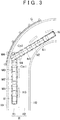
- FIG. 3 is a plan view useful for explaining determination of a collision between the own vehicle M that is going to enter a curve, and the oncoming vehicle N that is traveling on the curve.
- FIG. 3 shows own vehicle positions M1 - M4 as predicted positions of the own vehicle M to be reached at intervals of a preset time on the own vehicle course Cm1, and oncoming vehicle positions N1 - N4 as predicted positions of the oncoming vehicle N to be reached at intervals of a preset time on the oncoming vehicle course Cn1.
- the own vehicle position M1 and the oncoming vehicle position N1 are positions at which the own vehicle M and the oncoming vehicle N are expected to be located one second after they are located at the current positions, for example.
- the own vehicle position M2 and the oncoming vehicle position N2 are positions at which the own vehicle M and the oncoming vehicle N are expected to be located two seconds after they are located at the current positions, for example.
- the own vehicle position M3 and the oncoming vehicle position N3 are positions at which the own vehicle M and the oncoming vehicle N are expected to be located three seconds after they are located at the current positions, for example.
- the own vehicle position M4 and the oncoming vehicle position N4 are positions at which the own vehicle M and the oncoming vehicle N are expected to be located four seconds after they are located at the current positions, for example.
- the collision avoidance control system 1 determines that there is a point in time at which the own vehicle position M4 on the own vehicle course Cm1 overlaps the oncoming vehicle position N4 on the oncoming vehicle course Cn1.
- the collision avoidance control system 1 determines that there is a point in time at which the own vehicle position M4 on the own vehicle course Cm1 overlaps the oncoming vehicle position N4 on the oncoming vehicle course Cn1
- the system 1 performs avoidance control for avoiding a collision between the oncoming vehicle N and the own vehicle M.
- the oncoming vehicle N normally travels while going round the curve along the opposing traffic lane R2, and passes the own vehicle M traveling on the traffic lane R1 without colliding with the own vehicle M. Since there are a great number of scenes in which the own vehicle M and the oncoming vehicle N pass each other on a curve, the driver may feel strange or uncomfortable if the system performs avoidance control each time the oncoming vehicle N appears during traveling on a curve or in the vicinity of a curve.
- the collision avoidance control system 1 determines that the own vehicle M or the oncoming vehicle N is traveling on a curve
- the system 1 sets at least one of the first transfer prediction time and the second transfer prediction time to the shorter time, as compared with the case where neither of the own vehicle M and the oncoming vehicle N is traveling on a curve, so as to curb unnecessary avoidance control associated with the oncoming vehicle N.
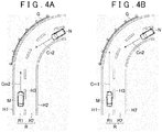
- FIG. 4A is a plan view showing the case where both of the first transfer prediction time of the own vehicle M and the second transfer prediction time of the oncoming vehicle N are set to the shorter time, in the situation shown in FIG. 2 .
- the system 1 may set both of the first transfer prediction time of the own vehicle M and the second transfer prediction time of the oncoming vehicle N to the shorter time.
- the collision avoidance control system 1 calculates the own vehicle course Cm2 and the oncoming vehicle course Cn2, using the first transfer prediction time and second transfer prediction time thus set to the shorter time.
- the own vehicle course Cm2 has a shorter length than the own vehicle course Cm1 shown in FIG. 2 .
- the oncoming vehicle course Cn2 has a shorter length than the oncoming vehicle course Cn1 shown in FIG. 2 .
- the collision avoidance control system 1 determines that there is no point in time at which one of the time-dependent own vehicle positions on the own vehicle course Cm2 overlaps a corresponding one of the time-dependent oncoming vehicle positions on the oncoming vehicle course Cn2, and does not perform avoidance control.
- FIG. 4B is a plan view showing the case where the second transfer prediction time of the oncoming vehicle N is set to the shorter time in the situation as shown in FIG. 2 .
- the system 1 may set the second transfer prediction time of the oncoming vehicle N to the shorter time.
- the first transfer prediction time of the own vehicle M is set to the normal time.
- the collision avoidance control system 1 calculates the own vehicle course Cm1, using the first transfer prediction time set to the normal time, and calculates the oncoming vehicle course Cn2, using the second transfer prediction time set to the shorter time.
- the collision avoidance control system 1 determines that there is no point in time at which one of the time-dependent own vehicle positions on the own vehicle course Cm1 overlaps a corresponding one of the time-dependent oncoming vehicle positions on the oncoming vehicle course Cn2, and does not perform avoidance control.
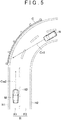
- FIG. 5 is a plan view showing the case where the first transfer prediction time of the own vehicle M is set to the shorter time in the situation as shown in FIG. 2 .
- the system 1 may set the first transfer prediction time of the own vehicle M to the shorter time.
- the second transfer prediction time of the oncoming vehicle N remains the normal time.
- the collision avoidance control system 1 calculates the own vehicle course Cm2, using the first transfer prediction time set to the shorter time, and calculates the oncoming vehicle course Cn1, using the second transfer prediction time set to the normal time.
- the collision avoidance control system 1 determines that there is no point in time at which one of the time-dependent own vehicle positions on the own vehicle course Cm2 overlaps a corresponding one of the time-dependent oncoming vehicle positions on the oncoming vehicle course Cn1, and does not perform avoidance control.
- FIG. 6A is a plan view showing a situation where both of the own vehicle and the oncoming vehicle are traveling on a curve.
- the collision avoidance control system 1 may set both of the first transfer prediction time of the own vehicle M and the second transfer prediction time of the oncoming vehicle N to the shorter time.
- the collision avoidance control system 1 may set only one of the first transfer prediction time of the own vehicle M and the second transfer prediction time of the oncoming vehicle N to the shorter time, even when both of the own vehicle M and the oncoming vehicle N are traveling on the curve,.
- FIG. 6B is a plan view showing a situation where the own vehicle is traveling on a curve, and the oncoming vehicle is going to enter the curve.
- the collision avoidance control system 1 may set both of the first transfer prediction time of the own vehicle M and the second transfer prediction time of the oncoming vehicle N to the shorter time.
- the collision avoidance control system 1 may set only one of the first transfer prediction time of the own vehicle M and the second transfer prediction time of the oncoming vehicle N to the shorter time.
- the collision avoidance control system 1 determines that there is no point in time at which corresponding ones of the time-dependent own vehicle positions and time-dependent oncoming vehicle positions on the respective courses overlap each other, and does not perform avoidance control. Accordingly, even when the own vehicle M or the oncoming vehicle N is traveling on a curve, the collision avoidance control system 1 is less likely or unlikely to perform unnecessary avoidance control associated with the oncoming vehicle N, as compared with the time when both of the first transfer prediction time of the own vehicle M and the second transfer prediction time of the oncoming vehicle N are set to the normal time (when the own vehicle course Cm1 and the oncoming vehicle course Cn1 are used).
- the collision avoidance control system 1 may calculate an own vehicle course Cm3 that is curved based on the steering angle of the own vehicle M. In this case, the collision avoidance control system 1 can reduce the possibility of erroneous determination regarding a collision between the own vehicle M and the oncoming vehicle N, as compared with the case where the own vehicle course Cm2 that is not curved based on the steering angle of the own vehicle M is employed.
- the collision avoidance control system 1 may set the transfer prediction time of one or both of the own vehicle M and the oncoming vehicle N which is/are determined as being traveling on a curve, to the shorter time. More specifically, when the collision avoidance control system 1 determines that only the own vehicle M is traveling on a curve, the system 1 sets the first transfer prediction time to the shorter time, and sets the second transfer prediction time to the normal time. When the collision avoidance control system 1 determines that only the oncoming vehicle N is traveling on a curve, the system 1 sets the first transfer prediction time to the normal time, and sets the second transfer prediction time to the shorter time. When the collision avoidance control system 1 determines that both of the own vehicle M and the oncoming vehicle N are traveling on a curve, the system 1 sets both of the first transfer prediction time and the second transfer prediction time to the shorter time.
- the collision avoidance control system 1 shown in FIG. 1 includes an ECU (Electronic Control Unit) 2, vehicle-mounted camera 3, laser radar 4, vehicle speed sensor 5, acceleration sensor 6, yaw rate sensor 7, steering sensor 8, communication unit 9, navigation system 10, and HMI (Human Machine Interface) 11.
- ECU Electronic Control Unit
- vehicle-mounted camera 3 laser radar 4, vehicle speed sensor 5, acceleration sensor 6, yaw rate sensor 7, steering sensor 8, communication unit 9, navigation system 10, and HMI (Human Machine Interface) 11.
- HMI Human Machine Interface
- the ECU 2 performs avoidance control for avoiding a collision between the own vehicle M and the oncoming vehicle N.
- the ECU 2 is an electronic control unit having CPU (Central Processing Unit), ROM (Read Only Memory), RAM (Random Access Memory), and so forth.
- the ECU 2 performs various controls, by loading programs stored in the ROM into the RAM, and causing the CPU to execute the programs.
- the ECU 2 may consist of two or more electronic control units.
- the vehicle-mounted camera 3 is provided on the rear side of a front windshield of the own vehicle M, for example, and captures an image of the front of the own vehicle M.
- the vehicle-mounted camera 3 transmits the captured image of the front of the own vehicle M to the ECU 2.
- the vehicle-mounted camera 3 may be a monocular camera, or a stereo camera.
- the stereo camera has two image pickup units that are located so as to reproduce a binocular disparity.
- the captured image (disparity image) of the stereo camera includes depth-direction information.
- the vehicle-mounted camera 3 may include two or more cameras that capture images of the surroundings of the own vehicle M.
- the laser radar 4 detects an obstacle outside the own vehicle M, using radio waves (such as millimeter waves).
- the laser radar 4 transmits radio waves to the surroundings of the own vehicle M, and receives the radio waves reflected by an obstacle, to thus detect the obstacle.
- the laser radar 4 transmits the detected obstacle information to the ECU 2.
- a millimeter-wave radar or a LIDAR may be used in place of the laser radar 4.
- the LIDAR detects an obstacle outside the own vehicle M, using light.
- the vehicle speed sensor 5 is a detector for detecting the speed of the own vehicle M.
- a wheel speed sensor may be used which is provided on a wheel of the own vehicle M or a driveshaft, or the like, that rotates as a unit with the wheel, for detecting the rotational speed of the wheel.
- the vehicle speed sensor 5 transmits the detected vehicle speed information (wheel speed information) to the ECU 2.
- the acceleration sensor 6 is a detector for detecting the acceleration of the own vehicle M.
- the acceleration sensor 6 includes a longitudinal acceleration sensor that detects the acceleration in the longitudinal direction of the own vehicle M, and a lateral acceleration sensor that detects the lateral acceleration of the own vehicle M, for example.
- the acceleration sensor 6 transmits the acceleration information of the own vehicle M to the ECU 2, for example.
- the yaw rate sensor 7 is a detector for detecting the yaw rate (rotation angular velocity) about the vertical axis passing the gravity center of the own vehicle M.
- a gyro sensor for example, may be used.
- the yaw rate sensor 7 transmits the detected yaw rate information of the own vehicle M to the ECU 2.
- the steering sensor 8 is provided on a steering shaft of the own vehicle, for example, and detects steering torque applied by the driver to the steering wheel and the steering angle.
- the steering sensor 8 transmits steering information concerning the detected steering torque and steering angle, to the ECU 2.
- the communication unit 9 is installed on the own vehicle M, and performs inter-vehicle communications with other vehicles around the own vehicle M. For example, the communication unit 9 obtains information of other vehicles (a preceding vehicle, an oncoming vehicle, etc.) around the own vehicle via inter-vehicle communications. The communication unit 9 may obtain information on a road on which the own vehicle travels, via road-vehicle communications with a road-side transmitter/ receiver (e.g., optical beacon) provided on the road.
- a road-side transmitter/ receiver e.g., optical beacon
- the navigation system 10 guides the driver of the own vehicle M to a preset destination.
- the navigation system 10 has a GPS receiving unit 10a for measuring the position of the own vehicle M, and a map database 10b in which map information is stored, for example.
- the GPS receiving unit 10a receives signals from three or more GPS satellites, for example, so as to measure the position of the own vehicle M (e.g., the longitude and latitude of the vehicle).
- the map information of the map database 10b includes, for example, location information of roads, road type information, road shape information (including a straight line and a curve that are discriminated from each other), location information of intersections or junctions, and so forth.
- the HMI 11 is an interface for transmitting and receiving information between the driver and the system.
- the HMI 11 includes, for example, a display panel on which image information is displayed for the driver, etc., and operational buttons, touch panel, or the like, with which the driver can perform input operation.
- the HMI 11 is connected to a loudspeaker of the own vehicle M.
- the HMI 11 displays image information according to a control signal from the ECU 2, on the display, and generates voice according to the control signal, from the loudspeaker.
- the collision avoidance control system 1 does not necessarily include the laser radar 4 if it has another sensor or camera with which the oncoming vehicle N can be detected. Also, the collision avoidance control system 1 does not necessarily include the vehicle speed sensor 5, acceleration sensor 6, yaw rate sensor 7, steering sensor 8, and the communication unit 9. Also, the collision avoidance control system 1 may include a GPS receiving unit 10a and a map database 10b, in place of the navigation system 10. The collision avoidance control system 1 does not necessarily include the navigation system 10, GPS receiving unit 10a, and the map database 10b.
- the collision avoidance control system 1 does not necessarily include the HMI 11, but may be configured to be able to generate a warning as avoidance control by means of a display or a loudspeaker provided in the own vehicle M. Also, the collision avoidance control system 1 may be configured to perform steering control or speed reduction control of the own vehicle M as avoidance control. In this case, the collision avoidance control system 1 may be configured to carry out only the avoidance control in the form of the steering control or the speed reduction control, without giving a warning.
- the ECU 2 includes an oncoming vehicle detecting unit 20, deceleration determining unit 21, own-vehicle curve traveling determining unit 22, oncoming-vehicle curve traveling determining unit 23, transfer prediction time setting unit 24, own vehicle course calculating unit 25, oncoming vehicle course calculating unit 26, determining unit 27, and an avoidance control unit 28.
- a part of the functions of the ECU 2 may be performed by a computer of a facility, such as an information management center, capable of communicating with the own vehicle M via the communication unit 9.
- the oncoming vehicle detecting unit 20 detects the oncoming vehicle N that travels in a direction opposite to that of the own vehicle M, based on an image captured by the vehicle-mounted camera 3 or obstacle information of the laser radar 4, for example.
- the oncoming vehicle detecting unit 20 detects an oncoming vehicle through known image processing, based on the image captured by the vehicle-mounted camera, for example.
- the oncoming vehicle detecting unit 20 may recognize white lines (such as a center line and a boundary of a vehicle traffic zone) that define the opposing traffic lane R2, based on the image captured by the vehicle-mounted camera for capturing the image around the own vehicle M, and detect another vehicle on the opposing traffic lane R2 as the oncoming vehicle N.
- the oncoming vehicle detecting unit 20 may detect another vehicle approaching the own vehicle M from around the own vehicle M as the oncoming vehicle N, based on the detection result of the laser radar.
- the oncoming vehicle detecting unit 20 may detect an oncoming vehicle, based on both of the image captured by the vehicle-mounted camera 3 and the obstacle information of the laser radar 4.
- the oncoming vehicle detecting unit 20 may detect an oncoming vehicle N, based on the position and traveling direction of another vehicle obtained by the communication unit 9 via inter-vehicle communications with the other vehicle.
- the oncoming vehicle detecting unit 20 may also detect an oncoming vehicle by known methods.
- the deceleration determining unit 21 determines whether the deceleration of the own vehicle M is equal to or larger than a first deceleration threshold value, based on acceleration information of the acceleration sensor 6, for example.
- the first deceleration threshold value is a threshold value used for determining whether the own vehicle M is being rapidly decelerated.
- the first deceleration threshold value may be a fixed value, or may vary according to the vehicle speed, for example.
- the deceleration determining unit 21 also determines whether the deceleration of the oncoming vehicle N is equal to or larger than a second deceleration threshold value, based on obstacle information of the laser radar 4, for example.
- the second deceleration threshold value is a threshold value used for determining whether the oncoming vehicle N is being rapidly decelerated.
- the second deceleration threshold value may be a fixed value, or may vary according to the vehicle speed, for example.
- the deceleration determining unit 21 may determine whether the deceleration of the oncoming vehicle N is equal to or larger than the second deceleration threshold value, based on the deceleration of the oncoming vehicle N obtained by the communication unit 9 via inter-vehicle communications with other vehicles.
- the collision avoidance control system 1 does not necessarily have the deceleration determining unit 21.
- the own-vehicle curve traveling determining unit 22 determines whether the own vehicle M is traveling on a curve, based on steering information of the steering sensor 8, for example.
- the own-vehicle curve traveling determining unit 22 determines that the own vehicle M is traveling on a curve, when the steering angle of the steering wheel operated by the driver of the own vehicle M becomes equal to or larger than a threshold value, based on the steering information of the steering sensor 8, for example.
- the own-vehicle curve traveling determining unit 22 may determine that the own vehicle M is traveling on a curve, using information concerning turn-signal lamps of the own vehicle M, as well as the steering information of the steering sensor 8, when the steering angle becomes equal to or larger than the threshold value in a condition where no turn-signal lamp is turned on.
- the own-vehicle curve traveling determining unit 22 may also determine whether the own vehicle M is traveling on a curve, through recognition of white lines around the own vehicle M, based on an image captured by the vehicle-mounted camera 3 (see FIG. 2 ).
- the own-vehicle curve traveling determining unit 22 can recognize a guardrail or a wall provided along the road on which the own vehicle M travels, based on the image captured by the vehicle-mounted camera 3 or obstacle information of the laser radar 4, it may determine whether the own vehicle is traveling on a curve, from the radius of curvature (when viewed from above) of the guardrail or wall.
- the collision avoidance control system 1 may determine whether the own vehicle is traveling on a curve, based on information on the position of the own vehicle and map information.
- the own-vehicle curve traveling determining unit 22 may also determine whether the own vehicle M is traveling on a curve by known methods.
- the oncoming-vehicle curve traveling determining unit 23 determines whether the oncoming vehicle N is traveling on a curve, based on the detection result of the oncoming vehicle detecting unit 20.
- the oncoming-vehicle curve traveling determining unit 23 determines whether the oncoming vehicle N detected by the oncoming vehicle detecting unit 20 is traveling on a curve, based on obstacle information of the laser radar 4, for example. More specifically, the oncoming-vehicle curve traveling determining unit 23 recognizes a velocity vector of the oncoming vehicle N from a change in the position of the oncoming vehicle N with time.
- the oncoming-vehicle curve traveling determining unit 23 After the oncoming-vehicle curve traveling determining unit 23 recognizes the velocity vector of the oncoming vehicle N a plurality of times, it determines whether the oncoming vehicle is traveling on a curve, based on the amount of change in the direction of the velocity vector (the amount of change in the traveling direction of the oncoming vehicle).
- the oncoming-vehicle curve traveling determining unit 23 may also determine that the oncoming vehicle N located in front of the own vehicle M is traveling on a curve, by recognizing the curve in front of the own vehicle M from the radius of curvature of the road R obtained through recognition of the white lines, based on the image captured by the vehicle-mounted camera 3. Similarly, when the oncoming-vehicle curve traveling determining unit 23 recognizes a guardrail G or a wall in front of the own vehicle M, based on the image captured by the vehicle-mounted camera 3, it may determine that the oncoming vehicle N is traveling on a curve, by recognizing the curve in front of the own vehicle M from the radius of curvature of the guardrail G or wall.
- the oncoming-vehicle curve traveling determining unit 23 may determine whether the oncoming vehicle N is traveling on a curve, based on both of the image captured by the vehicle-mounted camera 3 and obstacle information of the laser radar 4. In addition, the oncoming-vehicle curve traveling determining unit 23 may determine whether the oncoming vehicle N is traveling on a curve by known methods.
- the transfer prediction time setting unit 24 sets the first transfer prediction time of the own vehicle M and the second transfer prediction time of the oncoming vehicle N, based on the results of determination of the own-vehicle curve traveling determining unit 22 and the oncoming-vehicle curve traveling determining unit 23.
- the transfer prediction time setting unit 24 sets at least one of the first transfer prediction time of the own vehicle M and the second transfer prediction time of the oncoming vehicle N to a shorter length of time, as compared with the case where neither of the own vehicle M and the oncoming vehicle N is not traveling on a curve.
- the transfer prediction time setting unit may always set only the first transfer prediction time to the shorter time, or set only the second transfer prediction time to the shorter time.
- the transfer prediction time setting unit 24 may always set both of the first transfer prediction time and the second transfer prediction time to the shorter time.
- the first transfer prediction time and the second transfer prediction time may be the same length of time or different lengths of time.
- the transfer prediction time setting unit 24 may set the transfer prediction time corresponding to one of the own vehicle M and the oncoming vehicle N which is determined as being traveling on a curve, to the shorter time. Namely, when the own-vehicle curve traveling determining unit 22 determines that the own vehicle M is traveling on a curve, the transfer prediction time setting unit 24 sets the first transfer prediction time to the shorter time, and sets the second transfer prediction time to the normal time. When the oncoming-vehicle curve traveling determining unit 23 determines that the oncoming vehicle N is traveling on a curve, the transfer prediction time setting unit 24 sets the first transfer prediction time to the normal time, and sets the second transfer prediction time to the shorter time.
- the transfer prediction time setting unit 24 may basically set the first transfer prediction time of the own vehicle M and the second transfer prediction time of the oncoming vehicle N to the normal time, and may set at least one of the first transfer prediction time of the own vehicle M and the second transfer prediction time of the oncoming vehicle N to the shorter time, only when at least one of the own vehicle M and the oncoming vehicle N is traveling on a curve.
- the own vehicle course calculating unit 25 calculates the own vehicle course from the vehicle speed and traveling direction of the own vehicle M, based on vehicle speed information of the vehicle speed sensor 5, yaw rate information of the yaw rate sensor 7, and the first transfer prediction time set by the transfer prediction time setting unit 24, for example.
- the own vehicle course calculating unit 25 calculates the own vehicle course along which the own vehicle M is expected to proceed during the first transfer prediction time while keeping the current vehicle speed and traveling direction, for example.
- the own vehicle course calculating unit 25 may further calculate the own vehicle course in view of change of the traveling direction, based on steering information of the steering sensor 8 (see the own vehicle course Cm3 of FIG. 6B ). In another example, the own vehicle course calculating unit 25 may calculate the own vehicle course along which the own vehicle M is expected to proceed during the first transfer prediction time while keeping the current acceleration, based on acceleration information of the acceleration sensor 6, as well as the vehicle speed information of the vehicle speed sensor 5. In addition, the own vehicle course calculating unit 25 may calculate the own vehicle course by known methods.
- the own vehicle course calculating unit 25 also calculates time-dependent own vehicle positions on the own vehicle course, as well as the own vehicle course.
- the own vehicle course calculating unit 25 calculates own vehicle positions at which the own vehicle is expected to be located at intervals of a preset time on the own vehicle course, based on vehicle-speed information of the vehicle speed sensor 5, for example (see FIG. 3 ). For the own vehicle position, a range corresponding to the size of the own vehicle M is set, for example.
- the oncoming vehicle course calculating unit 26 calculates the oncoming vehicle course, based on obstacle information of the laser radar 4 and the second transfer prediction time set by the transfer prediction time setting unit 24, for example.
- the oncoming vehicle course calculating unit 26 calculates the oncoming vehicle course along which the oncoming vehicle N is expected to proceed during the second transfer prediction time while keeping the vehicle speed and traveling direction (direction of the velocity vector) of the oncoming vehicle N obtained from the obstacle information of the laser radar 4, for example.
- the oncoming vehicle course calculating unit 26 may calculate the oncoming vehicle course from the vehicle speed and traveling direction of the oncoming vehicle N obtained from the oncoming vehicle N via inter-vehicle communications of the communication unit 9.
- the oncoming vehicle course calculating unit 26 may calculate the own vehicle course by known methods.
- the oncoming vehicle course calculating unit 26 also calculates time-dependent oncoming vehicle positions on the oncoming vehicle course.
- the oncoming vehicle course calculating unit 26 calculates oncoming vehicle positions at which the oncoming vehicle is expected to be located at intervals of a preset time on the oncoming vehicle course, from the vehicle speed of the oncoming vehicle N, based on the obstacle information of the laser radar 4, for example (see FIG. 3 ).
- For the oncoming vehicle position a range corresponding to the estimated size of the oncoming vehicle N is set, based on the image captured by the vehicle-mounted camera 3 or the obstacle information of the laser radar 4, for example.
- the oncoming vehicle course calculating unit 26 estimates the size of the oncoming vehicle N, based on the image captured by the vehicle-mounted camera 3 or the obstacle information of the laser radar 4, by a known method, for example.
- the oncoming vehicle course calculating unit 26 does not necessarily estimate the size of the oncoming vehicle N, but may employ a preset range as the range of the oncoming vehicle position.
- the determining unit 27 determines whether there is any point in time at which one of the own vehicle positions on the own vehicle course calculated by the own vehicle course calculating unit 25 overlaps a corresponding one of the oncoming vehicle positions on the oncoming vehicle course calculated by the oncoming vehicle course calculating unit 26.
- the determining unit 27 determines that there is a point in time at which one of the own vehicle positions on the own vehicle course overlaps a corresponding one of the oncoming vehicle positions on the oncoming vehicle course.
- the avoidance control unit 28 When the determining unit 27 determines that there is a point in time at which one of the own vehicle positions on the own vehicle course overlaps a corresponding one of the oncoming vehicle positions on the oncoming vehicle course, the avoidance control unit 28 performs avoidance control for avoiding a collision between the oncoming vehicle N and the own vehicle M. As one example of the avoidance control, the avoidance control unit 28 transmits a control signal to the HMI 11. The HMI 11 gives a warning concerning the oncoming vehicle N to the driver via an image output or a voice output, based on the control signal from the avoidance control unit 28.
- the avoidance control unit 28 may transmit a control signal to an actuator (such as a throttle actuator, a brake actuator, and a steering actuator) for controlling traveling of the own vehicle M.
- the actuator performs steering control or speed reduction control on the own vehicle M, based on the control signal from the avoidance control unit 28.
- FIG. 7A and FIG 7B are a flowchart illustrating the collision avoidance control method of the collision avoidance control system 1 according to this embodiment.
- the ECU 2 of the collision avoidance control system 1 causes the oncoming vehicle detecting unit 20 to detect an oncoming vehicle N in step S101.
- the oncoming vehicle detecting unit 20 detects the oncoming vehicle N traveling in a direction opposite to that of the own vehicle M, based on obstacle information of the laser radar 4, for example. If no oncoming vehicle N is detected (S101: NO), the ECU 2 finishes the current cycle of the routine. Then, the ECU 2 executes step S101 again, after a lapse of a preset time (e.g., a period of time corresponding to the clock cycle of the ECU 2).
- a preset time e.g., a period of time corresponding to the clock cycle of the ECU 2.
- step S102 the ECU 2 causes the deceleration determining unit 21 to determine whether the deceleration of the own vehicle M is equal to or larger than the first deceleration threshold value, and determine whether the deceleration of the oncoming vehicle N is equal to or larger than the second deceleration threshold value. If the deceleration determining unit 21 determines that the deceleration of the own vehicle M is not equal to nor larger than the first deceleration threshold value, and determines that the deceleration of the oncoming vehicle N is not equal to nor larger than the second deceleration threshold value (S102: NO), the ECU 2 goes to step S103.
- the deceleration determining unit 21 determines that the deceleration of the own vehicle M is equal to or larger than the first deceleration threshold value, or determines that the deceleration of the oncoming vehicle N is equal to or larger than the second deceleration threshold value (S102: YES), the ECU 2 goes to step S104.
- Step S102 and step S103 may be changed in order. Also, step S102 is not necessarily executed, and step S102 may be eliminated.
- step S103 the ECU 2 causes the own-vehicle curve traveling determining unit 22 to determine whether the own vehicle M is traveling on a curve, and causes the oncoming-vehicle curve traveling determining unit 23 to determine whether the oncoming vehicle N is traveling on a curve.
- the own-vehicle curve traveling determining unit 22 determines whether the own vehicle M is traveling on a curve, based on steering information of the steering sensor 8, for example.
- the oncoming-vehicle curve traveling determining unit 23 determines whether the oncoming vehicle N is traveling on a curve, based on obstacle information of the laser radar 4, for example. If it is determined that neither of the own vehicle M and the oncoming vehicle N is traveling on a curve (S103: NO), the ECU 2 goes to step S104. If it is determined that the own vehicle M or the oncoming vehicle N is traveling on a curve (S103: YES), the ECU 2 goes to step S105.
- step S104 the ECU 2 causes the transfer prediction time setting unit 24 to set the first transfer prediction time and the second transfer prediction time to the normal time.
- the first transfer prediction time and the second transfer prediction time are set by default (initially set) to the normal time, there is no need to provide step S104.
- the ECU 2 proceeds to step S106.
- step S105 the ECU 2 causes the transfer prediction time setting unit 24 to set at least one of the first transfer prediction time and the second transfer prediction time to the shorter length of time than the normal time.
- the transfer prediction time setting unit 24 may shorten the transfer prediction time corresponding to one or both of the own vehicle M and the oncoming vehicle N which is/are determined as being traveling on a curve.
- the transfer prediction time setting unit 24 sets the first transfer prediction time of the own vehicle M to the shorter time, and sets the second transfer prediction time of the oncoming vehicle N to the normal time.
- the transfer prediction time setting unit 24 sets the first transfer prediction time of the own vehicle M to the normal time, and sets the second transfer prediction time of the oncoming vehicle N to the shorter time.
- the transfer prediction time setting unit 24 sets both of the first transfer prediction time of the own vehicle M and the second transfer prediction time of the oncoming vehicle N to the shorter time.
- the transfer prediction time setting unit 24 may also set only the first transfer prediction time of the own vehicle M to the shorter time, irrespective of the vehicle that is determined as being traveling on a curve.
- the transfer prediction time setting unit 24 may also set only the second transfer prediction time of the oncoming vehicle N to the shorter time, irrespective of the vehicle that is determined as being traveling on a curve.
- the transfer prediction time setting unit 24 may set both of the first transfer prediction time of the own vehicle M and the second transfer prediction time of the oncoming vehicle N to the shorter time, irrespective of the vehicle that is determined as being traveling on a curve.
- the transfer prediction time setting unit 24 sets the first transfer prediction time and the second transfer prediction time to the normal time by default, the unit 24 may set (change) only the transfer prediction time to be reduced.
- the ECU 2 goes to step S106 after setting the first transfer prediction time of the own vehicle M and the second transfer prediction time of the oncoming vehicle N.
- step S106 the ECU 2 causes the own vehicle course calculating unit 25 to calculate the own vehicle course, and cause the oncoming vehicle course calculating unit 26 to calculate the oncoming vehicle course.
- the own vehicle course calculating unit 25 calculates the own vehicle course along which the own vehicle M is expected to proceed during the first transfer prediction time, based on vehicle speed information of the vehicle speed sensor 5, yaw rate information of the yaw rate sensor 7, and the first transfer prediction time, for example.
- the own vehicle course calculating unit 25 calculates time-dependent own vehicle positions on the own vehicle course, as well as the own vehicle course.
- the oncoming vehicle course calculating unit 26 calculates the oncoming vehicle course along which the oncoming vehicle N is expected to proceed during the second transfer prediction time, based on obstacle information of the laser radar 4 and the second transfer prediction time, for example.
- the oncoming vehicle course calculating unit 26 calculates time-dependent oncoming vehicle positions on the oncoming vehicle course, as well as the oncoming vehicle course. After calculation of the own vehicle course and the oncoming vehicle course, the ECU 2 goes to step S107.
- step S107 the ECU 2 causes the determining unit 27 to determine whether there is any point in time at which one of the own vehicle positions on the own vehicle course overlaps a corresponding one of the oncoming vehicle positions on the oncoming vehicle course. If the determining unit 27 determines that there is no point in time at which one of the own vehicle positions on the own vehicle course overlaps a corresponding one of the oncoming vehicle positions on the oncoming vehicle course (S107: NO), the ECU 2 finishes the current cycle of the routine. Then, the ECU 2 executes step S101 again, after a lapse of a preset time.
- step S107 If the determining unit 27 determines that there is no point in time at which one of the own vehicle positions on the own vehicle course overlaps a corresponding one of the oncoming vehicle positions on the oncoming vehicle course, even if the own vehicle course and the oncoming vehicle course intersect with each other, the ECU 2 makes a negative decision (NO) in step S107. On the other hand, if the determining unit 27 determines that there is a point in time at which one of the own vehicle positions on the own vehicle course overlaps a corresponding one of the oncoming vehicle positions on the oncoming vehicle course (S107: YES), the ECU 2 goes to step S108.
- step S108 the ECU 2 causes the avoidance control unit 28 to perform avoidance control.
- the avoidance control unit 28 issues a warning concerning the oncoming vehicle N as avoidance control, by transmitting a control signal to the HMI 11, for example.
- the warning concerning the oncoming vehicle N is issued, for example, the ECU 2 finishes processing concerning the oncoming vehicle N.
- the collision avoidance control system 1 when it is determined that the own vehicle M or the oncoming vehicle N is traveling on a curve, at least one of the first transfer prediction time and the second transfer prediction time is set to the shorter time, as compared with the case where it is determined that neither of the own vehicle M and the oncoming vehicle N is traveling on a curve.
- the collision avoidance control system 1 when the own vehicle M or the oncoming vehicle N is traveling on a curve, at least one of the calculated own vehicle course and oncoming vehicle course is shortened.
- the transfer prediction time of one of the own vehicle M and the oncoming vehicle N which is traveling on a curve is set to the shorter time, so that unnecessary avoidance control in connection with curve traveling can be curbed while an appropriate collision determination can be made with respect to the vehicle that is not traveling on a curve.
- each of the first transfer prediction time and the second transfer prediction time is set to a preset normal time, so that appropriate chances of avoidance control can be ensured.
- the collision avoidance control system 1 may change the first transfer prediction time or the second transfer prediction time, according to a condition or conditions other than determination on curve traveling.
Landscapes
- Engineering & Computer Science (AREA)
- Automation & Control Theory (AREA)
- Transportation (AREA)
- Mechanical Engineering (AREA)
- Human Computer Interaction (AREA)
- Traffic Control Systems (AREA)
- Control Of Driving Devices And Active Controlling Of Vehicle (AREA)
Description
- The invention relates to a collision avoidance control system that performs avoidance control for avoiding a collision between an oncoming vehicle and an own vehicle.
- Japanese Patent Application Publication No.
2008-137396 JP 2008-137396 A -
US 2014/350785 discloses a collision mitigation apparatus which is installed in a vehicle and mitigates damage to the vehicle in occurrence of a collision. The apparatus is configured to detect an oncoming vehicle, to determine whether a curve is present in forward direction, to calculate an own vehicle course and time-dependent own vehicle positions, the own vehicle course being a course along which the own vehicle is expected to proceed, to calculate an oncoming vehicle course and time-depending oncoming vehicle positions, the oncoming vehicle course being a course along which the oncoming vehicle is expected to proceed, to calculate a time to collision, and to perform avoidance control for avoiding a collision with the oncoming vehicle. If a curve is detected in the forward direction, a threshold used for evaluating the time to collision is corrected to a smaller value, whereby the collision avoidance control is delayed. However, this document does not disclose at least setting a first transfer prediction time and a second transfer prediction time, such that at least one of the first transfer prediction time and the second transfer prediction time is set to a shorter time when it is determined that an own vehicle is traveling on a curve, or when it is determined that an oncoming vehicle is traveling on a curve, as compared with the time when neither of the own vehicle and the oncoming vehicle is traveling on a curve. -
US 2014/343749 discloses a collision mitigation apparatus including an object detecting section for detecting a collision object present in front of an own vehicle. - In the meantime, when at least one of the own vehicle and the oncoming vehicle is traveling on a curve, a situation where the traveling direction or course of the oncoming vehicle intersects with the course of the own vehicle takes place frequently. However, in the known system as described above, traveling conditions (such as straight traveling, and curve traveling) of the own vehicle and the oncoming vehicle are not taken into consideration when the collision possibility is predicted; therefore, avoidance control, such as warning, may be performed in unnecessary scenes.
- Thus, the present invention provides a collision avoidance control system that is able to curb unnecessary avoidance control involving an oncoming vehicle.
- According to one aspect of the invention, a collision avoidance control system includes an ECU. The ECU is configured to: detect an oncoming vehicle; perform avoidance control, the avoidance control being control for avoiding a collision between the oncoming vehicle and an own vehicle; determine whether the own vehicle is traveling on a curve; determine whether the oncoming vehicle is traveling on a curve, based on a result of the detection; setting a first transfer prediction time and a second transfer prediction time, such that at least one of the first transfer prediction time and the second transfer prediction time is set to a shorter time when it is determined that the own vehicle is traveling on a curve, or when it is determined that the oncoming vehicle is traveling on a curve, as compared with the time when neither of the own vehicle and the oncoming vehicle is traveling on a curve; calculate an own vehicle course and time-dependent own vehicle positions on the own vehicle course, based on a traveling direction of the own vehicle and a vehicle speed of the own vehicle, the own vehicle course being a course along which the own vehicle is expected to proceed during the first transfer prediction time; calculate an oncoming vehicle course and time-depending oncoming vehicle positions on the oncoming vehicle course, based on the result of the detection, the oncoming vehicle course being a course along which the oncoming vehicle is expected to proceed during the second transfer prediction time; determine whether there is a point in time at which one of the own vehicle positions on the own vehicle course overlaps a corresponding one of the oncoming vehicle positions on the oncoming vehicle course; and perform the avoidance control when it is determined that there is a point in time at which one of the own vehicle positions overlaps a corresponding one of the oncoming vehicle positions.
- When it is determined that the own vehicle or the oncoming vehicle is traveling on a curve, the collision avoidance system according to the above aspect of the invention sets at least one of the first transfer prediction time and the second transfer prediction time to the shorter time, as compared with the time when it is determined that neither of the own vehicle and the oncoming vehicle is traveling on a curve. Accordingly, with the collision avoidance control system, at least one of the calculated own vehicle course and oncoming vehicle course is shortened when the own vehicle or the oncoming vehicle is traveling on a curve; therefore, it is less likely to be determined that one of the own vehicle positions on the own vehicle course overlaps a corresponding one of the oncoming vehicle positions on the oncoming vehicle course, as compared with the time when the own vehicle course and the oncoming vehicle course are not shortened, and unnecessary avoidance control involving the oncoming vehicle can be curbed.
- In the collision avoidance control system according to the above aspect of the invention, when it is determined that the own vehicle is traveling on a curve, the ECU may set the first transfer prediction time to the shorter time, as compared with the time when it is determined that the own vehicle is not traveling on a curve. When it is determined that the oncoming vehicle is traveling on a curve, the ECU may set the second transfer prediction time to the shorter time, as compared with the time when it is determined that the oncoming vehicle is not traveling on a curve.
- With the above arrangement, the transfer prediction time of one of the own vehicle and the oncoming vehicle which is traveling on a curve is set to the shorter time, so that an appropriate collision determination can be made with respect to the vehicle that is not traveling on a curve, and unnecessary avoidance control concerning curve traveling can be curbed.
- In the collision avoidance control system according to above aspect of the invention, the ECU may determine whether a deceleration of the own vehicle is equal to or larger than a first deceleration threshold value, and determine whether a deceleration of the oncoming vehicle is equal to or larger than a second deceleration threshold value, based on a the result of the detection. When it is determined that the deceleration of the own vehicle is equal to or larger than the first deceleration threshold value, or when it is determined that the deceleration of the oncoming vehicle is equal to or larger than the second deceleration threshold value, each of the first transfer prediction time and the second transfer predicted time may be set to a preset time, irrespective of a result of determination as to whether the own vehicle is traveling on a curve, and a result of determination as to whether the oncoming vehicle is traveling on a curve.
- When the own vehicle or the oncoming vehicle is being rapidly decelerated, it is not desirable to reduce chances of avoidance control by setting the first transfer prediction time or the second transfer prediction time to the shorter time. Thus, each of the first transfer prediction time and the second transfer prediction time is set to a preset length of time, so that appropriate chances of avoidance control can be ensured.
- In the above aspect of the invention, the ECU may perform the avoidance control of the own vehicle.
- Another aspect of the invention is concerned with a control method of a collision avoidance control system. The collision avoidance control system includes an ECU. The control method includes: detecting an oncoming vehicle by the ECU; setting a first transfer prediction time and a second transfer prediction time, such that at least one of the first transfer prediction time and the second transfer prediction time is set to a shorter time when a first condition and a second condition are satisfied, as compared with the time when the first condition is not satisfied or the second condition is not satisfied, the first condition being that a deceleration of the own vehicle is smaller than a first deceleration threshold value, and a deceleration of the oncoming vehicle is smaller than a second deceleration threshold value, the second condition being that the own vehicle is traveling on a curve, or the oncoming vehicle is traveling on a curve; calculating an own vehicle course and an oncoming vehicle course by the ECU, the own vehicle course being a course along which the own vehicle is expected to proceed during the first transfer prediction time, the oncoming vehicle course being a course along which the oncoming vehicle is expected to proceed during the second transfer prediction time; and performing avoidance control of the own vehicle by the ECU when there is a point in time at which one of the own vehicle positions overlaps a corresponding one of the oncoming vehicle positions, the avoidance control being control for avoiding a collision between the oncoming vehicle and the own vehicle.
- According to the above aspect of the invention, the collision avoidance control system that can curb unnecessary avoidance control involving the oncoming vehicle is provided.
- Features, advantages, and technical and industrial significance of exemplary embodiments of the invention will be described below with reference to the accompanying drawings, in which like numerals denote like elements, and wherein:
-
FIG. 1 is a block diagram showing a collision avoidance control system according to one embodiment of the invention; -
FIG. 2 is a plan view showing an own vehicle course of an own vehicle that is going to enter a curve, and an oncoming vehicle course of an oncoming vehicle that is traveling on a curve; -
FIG. 3 is a plan view useful for explaining determination of a collision between the own vehicle that is going to enter the curve and the oncoming vehicle that is traveling on the curve; -
FIG. 4A is a plan view showing the case where both of a first transfer prediction time of the own vehicle and a second transfer prediction time of the oncoming vehicle are set to a shorter length of time, in the situation shown inFIG. 2 ; -
FIG. 4B is a plan view showing the case where the second transfer prediction time of the oncoming vehicle is set to the shorter time, in the situation shown inFIG. 2 ; -
FIG. 5 is a plan view showing a situation where the first transfer prediction time of the own vehicle is set to the shorter time, in the situation shown inFIG. 2 ; -
FIG. 6A is a plan view showing a situation where both of the own vehicle and the oncoming vehicle are traveling on a curve; -
FIG. 6B is a plan view showing a situation where the own vehicle is traveling on a curve and the oncoming vehicle is going to enter the curve; and -
FIG. 7A is a flowchart illustrating a collision avoidance control method of the collision avoidance control system according to the embodiment ofFIG. 1 . -
FIG. 7A is a flowchart illustrating a collision avoidance control method of the collision avoidance control system according to the embodiment ofFIG. 1 . - A preferred embodiment of the invention will be described in detail with reference to the drawings.
-
FIG. 1 is a block diagram showing a collision avoidance control system according to the embodiment. The collisionavoidance control system 1 shown inFIG. 1 performs avoidance control for avoiding a collision between an own vehicle and an oncoming vehicle. The collisionavoidance control system 1 is installed on a vehicle, such as a passenger car, for example. The vehicle may be an autonomous vehicle, or may be a vehicle that permits only manual driving. Here, the oncoming vehicle is another vehicle (including a two-wheel vehicle, as well as a four-wheel vehicle) that travels in a direction opposite to a traveling direction of the own vehicle, on a road on which the own vehicle travels. For example, the oncoming vehicle travels on an opposing traffic lane of the road. The avoidance control is control for avoiding a collision between the own vehicle and the oncoming vehicle. One example of the avoidance control is a warning given to the driver. Also, the avoidance control may be steering control or speed reduction control of the own vehicle for avoiding a collision with the oncoming vehicle. - The collision
avoidance control system 1 detects an oncoming vehicle, based on an image captured by a vehicle-mounted camera, or a detection result of a laser radar, for example. For example, the collisionavoidance control system 1 detects another vehicle approaching the own vehicle from the front thereof, as the oncoming vehicle, based on the image captured by the vehicle-mounted camera, or the detection result of the laser radar. - When the collision
avoidance control system 1 detects an oncoming vehicle, it determines whether the own vehicle is traveling on a curve, and also determines whether the oncoming vehicle is traveling on the curve. The curve means a section of a road which has a radius of curvature that is equal to or larger than a preset threshold value. The collisionavoidance control system 1 determines whether the own vehicle is traveling on a curve, based on driver's steering information of the own vehicle, for example. The collisionavoidance control system 1 may determine whether the own vehicle and the oncoming vehicle are traveling on a curve, from the radius of curvature of the road obtained through white-line recognition, based on an image captured by the vehicle-mounted camera. The collisionavoidance control system 1 may determine whether the oncoming vehicle is traveling on a curve, from changes in the direction of a velocity vector (vector that extends in the traveling direction of the oncoming vehicle) of the oncoming vehicle, based on the detection result of the laser radar. The manner of determining whether the own vehicle or the oncoming vehicle is traveling on a curve will be described in greater detail later. -
FIG. 2 is a plan view showing an own vehicle course of the own vehicle that is going to enter a curve, and an oncoming vehicle course of the oncoming vehicle that is traveling on the curve.FIG. 2 shows a road R having one lane on each side, traffic lane R1, opposing traffic lane R2, white line H1 (a boundary of a vehicle traffic zone on the traffic lane R1 side), white line H2 (a boundary of the vehicle traffic zone on the opposing traffic lane R2 side), white line H3 (center line), guardrail G, own vehicle M, oncoming vehicle N, own vehicle course Cm1, oncoming vehicle course Cn1, and a range D of an image captured by a vehicle-mounted camera. InFIG. 2 , the own vehicle M and the oncoming vehicle N travel at the same vehicle speed. - In a situation as shown in
FIG. 2 , the collisionavoidance control system 1 detects the oncoming vehicle N, based on the image captured by the vehicle-mounted camera, for example. Then, on the basis of the image captured by the vehicle-mounted camera, the collisionavoidance control system 1 determines that the own vehicle M is not traveling on the curve (i.e., is traveling on a straight line), from the radius of curvature of the road obtained by recognizing the white lines H1 - H3 included in the range D of the image captured by the vehicle-mounted camera. Meanwhile, the collisionavoidance control system 1 determines that the oncoming vehicle N is traveling on the curve, based on the detection result of the laser radar, for example. - The collision
avoidance control system 1 calculates the own vehicle course and the oncoming vehicle course used for collision determination, based on the result of determination as to whether the own vehicle M and the oncoming vehicle N are traveling on a curve. The own vehicle course is a course along which the own vehicle M is expected to travel during a first transfer prediction time. The oncoming vehicle course is a course along which the oncoming vehicle N is expected to travel during a second transfer prediction time. The collisionavoidance control system 1 sets the first transfer prediction time and the second transfer prediction time, prior to calculation of the own vehicle course and oncoming vehicle course used for collision determination. - The collision
avoidance control system 1 sets the first transfer prediction time and the second transfer prediction time, based on the result of determination as to whether the own vehicle M and the oncoming vehicle N are traveling on a curve. When the collisionavoidance control system 1 determines that the own vehicle M or the oncoming vehicle N is traveling on a curve, thesystem 1 sets at least one of the first transfer prediction time and the second transfer prediction time to a shorter length of time, as compared with the case where neither of the own vehicle M and the oncoming vehicle N is traveling on a curve. - More specifically, when the collision
avoidance control system 1 determines that neither of the own vehicle M and the oncoming vehicle N is not traveling on a curve, thesystem 1 sets the first transfer prediction time and the second transfer prediction time to a preset normal time. The normal time is a standard length of time that is appropriately selected in connection with calculation of a course used for collision determination. The normal time may be set to a length of time that is equal to or longer than 3.5 seconds and equal to or shorter than 5 seconds, for example. The normal time set for the first transfer prediction time may be different from the normal time set for the second transfer prediction time. - When the collision
avoidance control system 1 determines that the own vehicle M or the oncoming vehicle N is traveling on a curve, thesystem 1 sets at least one of the first transfer prediction time and the second transfer prediction time to the shorter time than the normal time. The shorter time may be set to a length of time that is equal to or longer than 1.5 seconds and equal to or shorter than 3 seconds, for example. The first transfer prediction time and the second transfer prediction time are not necessarily set to the same length of time, but may be different lengths of time - In
FIG. 2 andFIG. 3 that will be described later, both of the first transfer prediction time and the second transfer prediction time are set to the normal time, for the sake of explanation of the case where a collision is determined. - The collision
avoidance control system 1 calculates the own vehicle course Cm1 as a course along which the own vehicle M is expected to travel during the first transfer prediction time, based on the traveling direction of the own vehicle M and the vehicle speed of the own vehicle M. The length of the own vehicle course Cm1 is longer as the first transfer prediction time is longer, and the length of the own vehicle course Cm1 is shorter as the first transfer prediction time is shorter. The length of the own vehicle course Cm1 is longer as the vehicle speed of the own vehicle M is faster. - The collision
avoidance control system 1 also calculates time-dependent own vehicle positions on the own vehicle course Cm1, based on the vehicle speed of the own vehicle M. The time-dependent own vehicle positions on the own vehicle course Cm1 are predicted positions of the own vehicle M to be reached at intervals of a preset time (e.g., 1 second) on the own vehicle course Cm1, for example. - The collision
avoidance control system 1 calculates the oncoming vehicle course Cn1 as a course along which the oncoming vehicle N is expected to travel during the second transfer prediction time, based on the detection result of the laser radar, for example. The length of the oncoming vehicle course Cn1 is longer as the second transfer prediction time is longer, and the length of the oncoming vehicle course Cn1 is shorter as the second transfer prediction time is shorter. The length of the oncoming vehicle course Cn1 is longer as the vehicle speed of the oncoming vehicle N is faster. - The collision
avoidance control system 1 calculates the oncoming vehicle course Cn1 from the relative position and relative velocity of the oncoming vehicle N relative to the own vehicle M, based on the detection result of the laser radar, for example. The collisionavoidance control system 1 also calculates time-dependent oncoming vehicle positions on the oncoming vehicle course Cn1, based on the relative velocity of the oncoming vehicle N relative to the own vehicle M, for example. The time-dependent oncoming vehicle positions on the oncoming vehicle course Cn1 are predicted positions of the oncoming vehicle N to be reached at intervals of a preset time (e.g., 1 second) on the oncoming vehicle course Cn1, for example. - The collision
avoidance control system 1 determines whether there is any point in time at which one of the time-dependent own vehicle positions on the own vehicle course Cm1 overlaps a corresponding one of the time-dependent oncoming vehicle positions on the oncoming vehicle course Cn1, as a determination on a collision between the own vehicle M and the oncoming vehicle N. -
FIG. 3 is a plan view useful for explaining determination of a collision between the own vehicle M that is going to enter a curve, and the oncoming vehicle N that is traveling on the curve.FIG. 3 shows own vehicle positions M1 - M4 as predicted positions of the own vehicle M to be reached at intervals of a preset time on the own vehicle course Cm1, and oncoming vehicle positions N1 - N4 as predicted positions of the oncoming vehicle N to be reached at intervals of a preset time on the oncoming vehicle course Cn1. The own vehicle position M1 and the oncoming vehicle position N1 are positions at which the own vehicle M and the oncoming vehicle N are expected to be located one second after they are located at the current positions, for example. The own vehicle position M2 and the oncoming vehicle position N2 are positions at which the own vehicle M and the oncoming vehicle N are expected to be located two seconds after they are located at the current positions, for example. The own vehicle position M3 and the oncoming vehicle position N3 are positions at which the own vehicle M and the oncoming vehicle N are expected to be located three seconds after they are located at the current positions, for example. The own vehicle position M4 and the oncoming vehicle position N4 are positions at which the own vehicle M and the oncoming vehicle N are expected to be located four seconds after they are located at the current positions, for example. - As shown in
FIG. 3 , the own vehicle position M4 on the own vehicle course Cm1 overlaps the oncoming vehicle position N4 on the oncoming vehicle course Cn1. In this case, the collisionavoidance control system 1 determines that there is a point in time at which the own vehicle position M4 on the own vehicle course Cm1 overlaps the oncoming vehicle position N4 on the oncoming vehicle course Cn1. When the collisionavoidance control system 1 determines that there is a point in time at which the own vehicle position M4 on the own vehicle course Cm1 overlaps the oncoming vehicle position N4 on the oncoming vehicle course Cn1, thesystem 1 performs avoidance control for avoiding a collision between the oncoming vehicle N and the own vehicle M. - However, in the situation shown in
FIG. 3 , the oncoming vehicle N normally travels while going round the curve along the opposing traffic lane R2, and passes the own vehicle M traveling on the traffic lane R1 without colliding with the own vehicle M. Since there are a great number of scenes in which the own vehicle M and the oncoming vehicle N pass each other on a curve, the driver may feel strange or uncomfortable if the system performs avoidance control each time the oncoming vehicle N appears during traveling on a curve or in the vicinity of a curve. - Thus, when the collision
avoidance control system 1 according to this embodiment determines that the own vehicle M or the oncoming vehicle N is traveling on a curve, thesystem 1 sets at least one of the first transfer prediction time and the second transfer prediction time to the shorter time, as compared with the case where neither of the own vehicle M and the oncoming vehicle N is traveling on a curve, so as to curb unnecessary avoidance control associated with the oncoming vehicle N. In the following, some cases will be specifically described with reference to the drawings. -
FIG. 4A is a plan view showing the case where both of the first transfer prediction time of the own vehicle M and the second transfer prediction time of the oncoming vehicle N are set to the shorter time, in the situation shown inFIG. 2 . As shown inFIG. 4A , when the collisionavoidance control system 1 determines that the oncoming vehicle N is traveling on a curve, thesystem 1 may set both of the first transfer prediction time of the own vehicle M and the second transfer prediction time of the oncoming vehicle N to the shorter time. The collisionavoidance control system 1 calculates the own vehicle course Cm2 and the oncoming vehicle course Cn2, using the first transfer prediction time and second transfer prediction time thus set to the shorter time. The own vehicle course Cm2 has a shorter length than the own vehicle course Cm1 shown inFIG. 2 . The oncoming vehicle course Cn2 has a shorter length than the oncoming vehicle course Cn1 shown inFIG. 2 . In the situation shown inFIG. 4A , the collisionavoidance control system 1 determines that there is no point in time at which one of the time-dependent own vehicle positions on the own vehicle course Cm2 overlaps a corresponding one of the time-dependent oncoming vehicle positions on the oncoming vehicle course Cn2, and does not perform avoidance control. -
FIG. 4B is a plan view showing the case where the second transfer prediction time of the oncoming vehicle N is set to the shorter time in the situation as shown inFIG. 2 . As shown inFIG. 4B , when the collisionavoidance control system 1 determines that the oncoming vehicle N is traveling on a curve, thesystem 1 may set the second transfer prediction time of the oncoming vehicle N to the shorter time. In this case, the first transfer prediction time of the own vehicle M is set to the normal time. The collisionavoidance control system 1 calculates the own vehicle course Cm1, using the first transfer prediction time set to the normal time, and calculates the oncoming vehicle course Cn2, using the second transfer prediction time set to the shorter time. In the situation shown inFIG. 4B , the collisionavoidance control system 1 determines that there is no point in time at which one of the time-dependent own vehicle positions on the own vehicle course Cm1 overlaps a corresponding one of the time-dependent oncoming vehicle positions on the oncoming vehicle course Cn2, and does not perform avoidance control. -
FIG. 5 is a plan view showing the case where the first transfer prediction time of the own vehicle M is set to the shorter time in the situation as shown inFIG. 2 . As shown inFIG. 5 , when the collisionavoidance control system 1 determines that the oncoming vehicle N is traveling on a curve, thesystem 1 may set the first transfer prediction time of the own vehicle M to the shorter time. In this case, the second transfer prediction time of the oncoming vehicle N remains the normal time. The collisionavoidance control system 1 calculates the own vehicle course Cm2, using the first transfer prediction time set to the shorter time, and calculates the oncoming vehicle course Cn1, using the second transfer prediction time set to the normal time. In the situation shown inFIG. 5 , the collisionavoidance control system 1 determines that there is no point in time at which one of the time-dependent own vehicle positions on the own vehicle course Cm2 overlaps a corresponding one of the time-dependent oncoming vehicle positions on the oncoming vehicle course Cn1, and does not perform avoidance control. -
FIG. 6A is a plan view showing a situation where both of the own vehicle and the oncoming vehicle are traveling on a curve. When both of the own vehicle M and the oncoming vehicle N are traveling on the curve, as shown inFIG. 6A , the collisionavoidance control system 1 may set both of the first transfer prediction time of the own vehicle M and the second transfer prediction time of the oncoming vehicle N to the shorter time. The collisionavoidance control system 1 may set only one of the first transfer prediction time of the own vehicle M and the second transfer prediction time of the oncoming vehicle N to the shorter time, even when both of the own vehicle M and the oncoming vehicle N are traveling on the curve,. -
FIG. 6B is a plan view showing a situation where the own vehicle is traveling on a curve, and the oncoming vehicle is going to enter the curve. When the own vehicle M is traveling on a curve, and the oncoming vehicle N is not traveling on the curve (but traveling straight), as shown inFIG. 6B , the collisionavoidance control system 1 may set both of the first transfer prediction time of the own vehicle M and the second transfer prediction time of the oncoming vehicle N to the shorter time. Alternatively, when the own vehicle M is traveling on a curve, and the oncoming vehicle N is not traveling on the curve, the collisionavoidance control system 1 may set only one of the first transfer prediction time of the own vehicle M and the second transfer prediction time of the oncoming vehicle N to the shorter time. - In the situations shown in
FIG. 6A and FIG. 6B as described above, too, the collisionavoidance control system 1 determines that there is no point in time at which corresponding ones of the time-dependent own vehicle positions and time-dependent oncoming vehicle positions on the respective courses overlap each other, and does not perform avoidance control. Accordingly, even when the own vehicle M or the oncoming vehicle N is traveling on a curve, the collisionavoidance control system 1 is less likely or unlikely to perform unnecessary avoidance control associated with the oncoming vehicle N, as compared with the time when both of the first transfer prediction time of the own vehicle M and the second transfer prediction time of the oncoming vehicle N are set to the normal time (when the own vehicle course Cm1 and the oncoming vehicle course Cn1 are used). - Also, as shown in
FIG. 6B , the collisionavoidance control system 1 may calculate an own vehicle course Cm3 that is curved based on the steering angle of the own vehicle M. In this case, the collisionavoidance control system 1 can reduce the possibility of erroneous determination regarding a collision between the own vehicle M and the oncoming vehicle N, as compared with the case where the own vehicle course Cm2 that is not curved based on the steering angle of the own vehicle M is employed. - The collision
avoidance control system 1 may set the transfer prediction time of one or both of the own vehicle M and the oncoming vehicle N which is/are determined as being traveling on a curve, to the shorter time. More specifically, when the collisionavoidance control system 1 determines that only the own vehicle M is traveling on a curve, thesystem 1 sets the first transfer prediction time to the shorter time, and sets the second transfer prediction time to the normal time. When the collisionavoidance control system 1 determines that only the oncoming vehicle N is traveling on a curve, thesystem 1 sets the first transfer prediction time to the normal time, and sets the second transfer prediction time to the shorter time. When the collisionavoidance control system 1 determines that both of the own vehicle M and the oncoming vehicle N are traveling on a curve, thesystem 1 sets both of the first transfer prediction time and the second transfer prediction time to the shorter time. - In the following, the configuration of the collision
avoidance control system 1 according to this embodiment will be described. The collisionavoidance control system 1 shown inFIG. 1 includes an ECU (Electronic Control Unit) 2, vehicle-mountedcamera 3,laser radar 4,vehicle speed sensor 5,acceleration sensor 6,yaw rate sensor 7, steeringsensor 8,communication unit 9,navigation system 10, and HMI (Human Machine Interface) 11. - The
ECU 2 performs avoidance control for avoiding a collision between the own vehicle M and the oncoming vehicleN. The ECU 2 is an electronic control unit having CPU (Central Processing Unit), ROM (Read Only Memory), RAM (Random Access Memory), and so forth. TheECU 2 performs various controls, by loading programs stored in the ROM into the RAM, and causing the CPU to execute the programs. TheECU 2 may consist of two or more electronic control units. - The vehicle-mounted
camera 3 is provided on the rear side of a front windshield of the own vehicle M, for example, and captures an image of the front of the own vehicle M. The vehicle-mountedcamera 3 transmits the captured image of the front of the own vehicle M to theECU 2. The vehicle-mountedcamera 3 may be a monocular camera, or a stereo camera. The stereo camera has two image pickup units that are located so as to reproduce a binocular disparity. The captured image (disparity image) of the stereo camera includes depth-direction information. The vehicle-mountedcamera 3 may include two or more cameras that capture images of the surroundings of the own vehicle M. - The
laser radar 4 detects an obstacle outside the own vehicle M, using radio waves (such as millimeter waves). Thelaser radar 4 transmits radio waves to the surroundings of the own vehicle M, and receives the radio waves reflected by an obstacle, to thus detect the obstacle. Thelaser radar 4 transmits the detected obstacle information to theECU 2. A millimeter-wave radar or a LIDAR may be used in place of thelaser radar 4. The LIDAR detects an obstacle outside the own vehicle M, using light. - The
vehicle speed sensor 5 is a detector for detecting the speed of the own vehicle M. As thevehicle speed sensor 5, a wheel speed sensor may be used which is provided on a wheel of the own vehicle M or a driveshaft, or the like, that rotates as a unit with the wheel, for detecting the rotational speed of the wheel. Thevehicle speed sensor 5 transmits the detected vehicle speed information (wheel speed information) to theECU 2. - The
acceleration sensor 6 is a detector for detecting the acceleration of the own vehicle M. Theacceleration sensor 6 includes a longitudinal acceleration sensor that detects the acceleration in the longitudinal direction of the own vehicle M, and a lateral acceleration sensor that detects the lateral acceleration of the own vehicle M, for example. Theacceleration sensor 6 transmits the acceleration information of the own vehicle M to theECU 2, for example. - The
yaw rate sensor 7 is a detector for detecting the yaw rate (rotation angular velocity) about the vertical axis passing the gravity center of the own vehicle M. As theyaw rate sensor 7, a gyro sensor, for example, may be used. Theyaw rate sensor 7 transmits the detected yaw rate information of the own vehicle M to theECU 2. - The
steering sensor 8 is provided on a steering shaft of the own vehicle, for example, and detects steering torque applied by the driver to the steering wheel and the steering angle. Thesteering sensor 8 transmits steering information concerning the detected steering torque and steering angle, to theECU 2. - The
communication unit 9 is installed on the own vehicle M, and performs inter-vehicle communications with other vehicles around the own vehicle M. For example, thecommunication unit 9 obtains information of other vehicles (a preceding vehicle, an oncoming vehicle, etc.) around the own vehicle via inter-vehicle communications. Thecommunication unit 9 may obtain information on a road on which the own vehicle travels, via road-vehicle communications with a road-side transmitter/ receiver (e.g., optical beacon) provided on the road. - The
navigation system 10 guides the driver of the own vehicle M to a preset destination. Thenavigation system 10 has aGPS receiving unit 10a for measuring the position of the own vehicle M, and amap database 10b in which map information is stored, for example. TheGPS receiving unit 10a receives signals from three or more GPS satellites, for example, so as to measure the position of the own vehicle M (e.g., the longitude and latitude of the vehicle). The map information of themap database 10b includes, for example, location information of roads, road type information, road shape information (including a straight line and a curve that are discriminated from each other), location information of intersections or junctions, and so forth. - The
HMI 11 is an interface for transmitting and receiving information between the driver and the system. TheHMI 11 includes, for example, a display panel on which image information is displayed for the driver, etc., and operational buttons, touch panel, or the like, with which the driver can perform input operation. Also, theHMI 11 is connected to a loudspeaker of the own vehicleM. The HMI 11 displays image information according to a control signal from theECU 2, on the display, and generates voice according to the control signal, from the loudspeaker. - The collision
avoidance control system 1 does not necessarily include thelaser radar 4 if it has another sensor or camera with which the oncoming vehicle N can be detected. Also, the collisionavoidance control system 1 does not necessarily include thevehicle speed sensor 5,acceleration sensor 6,yaw rate sensor 7, steeringsensor 8, and thecommunication unit 9. Also, the collisionavoidance control system 1 may include aGPS receiving unit 10a and amap database 10b, in place of thenavigation system 10. The collisionavoidance control system 1 does not necessarily include thenavigation system 10,GPS receiving unit 10a, and themap database 10b. - Further, the collision
avoidance control system 1 does not necessarily include theHMI 11, but may be configured to be able to generate a warning as avoidance control by means of a display or a loudspeaker provided in the own vehicle M. Also, the collisionavoidance control system 1 may be configured to perform steering control or speed reduction control of the own vehicle M as avoidance control. In this case, the collisionavoidance control system 1 may be configured to carry out only the avoidance control in the form of the steering control or the speed reduction control, without giving a warning. - Next, the functional configuration of the
ECU 2 will be described. TheECU 2 includes an oncomingvehicle detecting unit 20,deceleration determining unit 21, own-vehicle curve traveling determiningunit 22, oncoming-vehicle curve traveling determiningunit 23, transfer predictiontime setting unit 24, own vehiclecourse calculating unit 25, oncoming vehiclecourse calculating unit 26, determiningunit 27, and anavoidance control unit 28. A part of the functions of theECU 2 may be performed by a computer of a facility, such as an information management center, capable of communicating with the own vehicle M via thecommunication unit 9. - The oncoming
vehicle detecting unit 20 detects the oncoming vehicle N that travels in a direction opposite to that of the own vehicle M, based on an image captured by the vehicle-mountedcamera 3 or obstacle information of thelaser radar 4, for example. The oncomingvehicle detecting unit 20 detects an oncoming vehicle through known image processing, based on the image captured by the vehicle-mounted camera, for example. The oncomingvehicle detecting unit 20 may recognize white lines (such as a center line and a boundary of a vehicle traffic zone) that define the opposing traffic lane R2, based on the image captured by the vehicle-mounted camera for capturing the image around the own vehicle M, and detect another vehicle on the opposing traffic lane R2 as the oncoming vehicle N. The oncomingvehicle detecting unit 20 may detect another vehicle approaching the own vehicle M from around the own vehicle M as the oncoming vehicle N, based on the detection result of the laser radar. The oncomingvehicle detecting unit 20 may detect an oncoming vehicle, based on both of the image captured by the vehicle-mountedcamera 3 and the obstacle information of thelaser radar 4. The oncomingvehicle detecting unit 20 may detect an oncoming vehicle N, based on the position and traveling direction of another vehicle obtained by thecommunication unit 9 via inter-vehicle communications with the other vehicle. The oncomingvehicle detecting unit 20 may also detect an oncoming vehicle by known methods. - The
deceleration determining unit 21 determines whether the deceleration of the own vehicle M is equal to or larger than a first deceleration threshold value, based on acceleration information of theacceleration sensor 6, for example. The first deceleration threshold value is a threshold value used for determining whether the own vehicle M is being rapidly decelerated. The first deceleration threshold value may be a fixed value, or may vary according to the vehicle speed, for example. - The
deceleration determining unit 21 also determines whether the deceleration of the oncoming vehicle N is equal to or larger than a second deceleration threshold value, based on obstacle information of thelaser radar 4, for example. The second deceleration threshold value is a threshold value used for determining whether the oncoming vehicle N is being rapidly decelerated. The second deceleration threshold value may be a fixed value, or may vary according to the vehicle speed, for example. Thedeceleration determining unit 21 may determine whether the deceleration of the oncoming vehicle N is equal to or larger than the second deceleration threshold value, based on the deceleration of the oncoming vehicle N obtained by thecommunication unit 9 via inter-vehicle communications with other vehicles. The collisionavoidance control system 1 does not necessarily have thedeceleration determining unit 21. - The own-vehicle curve traveling determining
unit 22 determines whether the own vehicle M is traveling on a curve, based on steering information of thesteering sensor 8, for example. The own-vehicle curve traveling determiningunit 22 determines that the own vehicle M is traveling on a curve, when the steering angle of the steering wheel operated by the driver of the own vehicle M becomes equal to or larger than a threshold value, based on the steering information of thesteering sensor 8, for example. The own-vehicle curve traveling determiningunit 22 may determine that the own vehicle M is traveling on a curve, using information concerning turn-signal lamps of the own vehicle M, as well as the steering information of thesteering sensor 8, when the steering angle becomes equal to or larger than the threshold value in a condition where no turn-signal lamp is turned on. - The own-vehicle curve traveling determining
unit 22 may also determine whether the own vehicle M is traveling on a curve, through recognition of white lines around the own vehicle M, based on an image captured by the vehicle-mounted camera 3 (seeFIG. 2 ). When the own-vehicle curve traveling determiningunit 22 can recognize a guardrail or a wall provided along the road on which the own vehicle M travels, based on the image captured by the vehicle-mountedcamera 3 or obstacle information of thelaser radar 4, it may determine whether the own vehicle is traveling on a curve, from the radius of curvature (when viewed from above) of the guardrail or wall. The collisionavoidance control system 1 may determine whether the own vehicle is traveling on a curve, based on information on the position of the own vehicle and map information. In addition, the own-vehicle curve traveling determiningunit 22 may also determine whether the own vehicle M is traveling on a curve by known methods. - The oncoming-vehicle curve traveling determining
unit 23 determines whether the oncoming vehicle N is traveling on a curve, based on the detection result of the oncomingvehicle detecting unit 20. The oncoming-vehicle curve traveling determiningunit 23 determines whether the oncoming vehicle N detected by the oncomingvehicle detecting unit 20 is traveling on a curve, based on obstacle information of thelaser radar 4, for example. More specifically, the oncoming-vehicle curve traveling determiningunit 23 recognizes a velocity vector of the oncoming vehicle N from a change in the position of the oncoming vehicle N with time. After the oncoming-vehicle curve traveling determiningunit 23 recognizes the velocity vector of the oncoming vehicle N a plurality of times, it determines whether the oncoming vehicle is traveling on a curve, based on the amount of change in the direction of the velocity vector (the amount of change in the traveling direction of the oncoming vehicle). - The oncoming-vehicle curve traveling determining
unit 23 may also determine that the oncoming vehicle N located in front of the own vehicle M is traveling on a curve, by recognizing the curve in front of the own vehicle M from the radius of curvature of the road R obtained through recognition of the white lines, based on the image captured by the vehicle-mountedcamera 3. Similarly, when the oncoming-vehicle curve traveling determiningunit 23 recognizes a guardrail G or a wall in front of the own vehicle M, based on the image captured by the vehicle-mountedcamera 3, it may determine that the oncoming vehicle N is traveling on a curve, by recognizing the curve in front of the own vehicle M from the radius of curvature of the guardrail G or wall. The oncoming-vehicle curve traveling determiningunit 23 may determine whether the oncoming vehicle N is traveling on a curve, based on both of the image captured by the vehicle-mountedcamera 3 and obstacle information of thelaser radar 4. In addition, the oncoming-vehicle curve traveling determiningunit 23 may determine whether the oncoming vehicle N is traveling on a curve by known methods. - The transfer prediction
time setting unit 24 sets the first transfer prediction time of the own vehicle M and the second transfer prediction time of the oncoming vehicle N, based on the results of determination of the own-vehicle curve traveling determiningunit 22 and the oncoming-vehicle curve traveling determiningunit 23. When the own-vehicle curve traveling determiningunit 22 determines that the own vehicle M is traveling on a curve, or the oncoming-vehicle curve traveling determiningunit 23 determines that the oncoming vehicle N is traveling on a curve, the transfer predictiontime setting unit 24 sets at least one of the first transfer prediction time of the own vehicle M and the second transfer prediction time of the oncoming vehicle N to a shorter length of time, as compared with the case where neither of the own vehicle M and the oncoming vehicle N is not traveling on a curve. When it is determined that the own vehicle M or the oncoming vehicle N is traveling on a curve, the transfer prediction time setting unit may always set only the first transfer prediction time to the shorter time, or set only the second transfer prediction time to the shorter time. In another example, when it is determined that the own vehicle M or the oncoming vehicle N is traveling on a curve, the transfer predictiontime setting unit 24 may always set both of the first transfer prediction time and the second transfer prediction time to the shorter time. The first transfer prediction time and the second transfer prediction time may be the same length of time or different lengths of time. - The transfer prediction
time setting unit 24 may set the transfer prediction time corresponding to one of the own vehicle M and the oncoming vehicle N which is determined as being traveling on a curve, to the shorter time. Namely, when the own-vehicle curve traveling determiningunit 22 determines that the own vehicle M is traveling on a curve, the transfer predictiontime setting unit 24 sets the first transfer prediction time to the shorter time, and sets the second transfer prediction time to the normal time. When the oncoming-vehicle curve traveling determiningunit 23 determines that the oncoming vehicle N is traveling on a curve, the transfer predictiontime setting unit 24 sets the first transfer prediction time to the normal time, and sets the second transfer prediction time to the shorter time. - The transfer prediction
time setting unit 24 may basically set the first transfer prediction time of the own vehicle M and the second transfer prediction time of the oncoming vehicle N to the normal time, and may set at least one of the first transfer prediction time of the own vehicle M and the second transfer prediction time of the oncoming vehicle N to the shorter time, only when at least one of the own vehicle M and the oncoming vehicle N is traveling on a curve. - The own vehicle
course calculating unit 25 calculates the own vehicle course from the vehicle speed and traveling direction of the own vehicle M, based on vehicle speed information of thevehicle speed sensor 5, yaw rate information of theyaw rate sensor 7, and the first transfer prediction time set by the transfer predictiontime setting unit 24, for example. The own vehiclecourse calculating unit 25 calculates the own vehicle course along which the own vehicle M is expected to proceed during the first transfer prediction time while keeping the current vehicle speed and traveling direction, for example. - The own vehicle
course calculating unit 25 may further calculate the own vehicle course in view of change of the traveling direction, based on steering information of the steering sensor 8 (see the own vehicle course Cm3 ofFIG. 6B ). In another example, the own vehiclecourse calculating unit 25 may calculate the own vehicle course along which the own vehicle M is expected to proceed during the first transfer prediction time while keeping the current acceleration, based on acceleration information of theacceleration sensor 6, as well as the vehicle speed information of thevehicle speed sensor 5. In addition, the own vehiclecourse calculating unit 25 may calculate the own vehicle course by known methods. - The own vehicle
course calculating unit 25 also calculates time-dependent own vehicle positions on the own vehicle course, as well as the own vehicle course. The own vehiclecourse calculating unit 25 calculates own vehicle positions at which the own vehicle is expected to be located at intervals of a preset time on the own vehicle course, based on vehicle-speed information of thevehicle speed sensor 5, for example (seeFIG. 3 ). For the own vehicle position, a range corresponding to the size of the own vehicle M is set, for example. - The oncoming vehicle
course calculating unit 26 calculates the oncoming vehicle course, based on obstacle information of thelaser radar 4 and the second transfer prediction time set by the transfer predictiontime setting unit 24, for example. The oncoming vehiclecourse calculating unit 26 calculates the oncoming vehicle course along which the oncoming vehicle N is expected to proceed during the second transfer prediction time while keeping the vehicle speed and traveling direction (direction of the velocity vector) of the oncoming vehicle N obtained from the obstacle information of thelaser radar 4, for example. The oncoming vehiclecourse calculating unit 26 may calculate the oncoming vehicle course from the vehicle speed and traveling direction of the oncoming vehicle N obtained from the oncoming vehicle N via inter-vehicle communications of thecommunication unit 9. In addition, the oncoming vehiclecourse calculating unit 26 may calculate the own vehicle course by known methods. - The oncoming vehicle
course calculating unit 26 also calculates time-dependent oncoming vehicle positions on the oncoming vehicle course. The oncoming vehiclecourse calculating unit 26 calculates oncoming vehicle positions at which the oncoming vehicle is expected to be located at intervals of a preset time on the oncoming vehicle course, from the vehicle speed of the oncoming vehicle N, based on the obstacle information of thelaser radar 4, for example (seeFIG. 3 ). For the oncoming vehicle position, a range corresponding to the estimated size of the oncoming vehicle N is set, based on the image captured by the vehicle-mountedcamera 3 or the obstacle information of thelaser radar 4, for example. The oncoming vehiclecourse calculating unit 26 estimates the size of the oncoming vehicle N, based on the image captured by the vehicle-mountedcamera 3 or the obstacle information of thelaser radar 4, by a known method, for example. The oncoming vehiclecourse calculating unit 26 does not necessarily estimate the size of the oncoming vehicle N, but may employ a preset range as the range of the oncoming vehicle position. - The determining
unit 27 determines whether there is any point in time at which one of the own vehicle positions on the own vehicle course calculated by the own vehiclecourse calculating unit 25 overlaps a corresponding one of the oncoming vehicle positions on the oncoming vehicle course calculated by the oncoming vehiclecourse calculating unit 26. When the range of the own vehicle position M4 at a certain point in time overlaps the range of the oncoming vehicle position N4 at the same point in time in a plan view, as shown inFIG. 3 , for example, the determiningunit 27 determines that there is a point in time at which one of the own vehicle positions on the own vehicle course overlaps a corresponding one of the oncoming vehicle positions on the oncoming vehicle course. - When the determining
unit 27 determines that there is a point in time at which one of the own vehicle positions on the own vehicle course overlaps a corresponding one of the oncoming vehicle positions on the oncoming vehicle course, theavoidance control unit 28 performs avoidance control for avoiding a collision between the oncoming vehicle N and the own vehicle M. As one example of the avoidance control, theavoidance control unit 28 transmits a control signal to theHMI 11. TheHMI 11 gives a warning concerning the oncoming vehicle N to the driver via an image output or a voice output, based on the control signal from theavoidance control unit 28. As another example of the avoidance control, theavoidance control unit 28 may transmit a control signal to an actuator (such as a throttle actuator, a brake actuator, and a steering actuator) for controlling traveling of the own vehicle M. In this case, the actuator performs steering control or speed reduction control on the own vehicle M, based on the control signal from theavoidance control unit 28. - Next, a collision avoidance control method of the collision
avoidance control system 1 according to this embodiment will be described with reference toFIG. 7A andFIG 7B .FIG. 7A andFIG 7B are a flowchart illustrating the collision avoidance control method of the collisionavoidance control system 1 according to this embodiment. - As shown in
FIG. 7A andFIG 7B , theECU 2 of the collisionavoidance control system 1 causes the oncomingvehicle detecting unit 20 to detect an oncoming vehicle N in step S101. The oncomingvehicle detecting unit 20 detects the oncoming vehicle N traveling in a direction opposite to that of the own vehicle M, based on obstacle information of thelaser radar 4, for example. If no oncoming vehicle N is detected (S101: NO), theECU 2 finishes the current cycle of the routine. Then, theECU 2 executes step S101 again, after a lapse of a preset time (e.g., a period of time corresponding to the clock cycle of the ECU 2). When the oncoming vehicle N is detected (S101: YES), theECU 2 goes to step S102. - In step S102, the
ECU 2 causes thedeceleration determining unit 21 to determine whether the deceleration of the own vehicle M is equal to or larger than the first deceleration threshold value, and determine whether the deceleration of the oncoming vehicle N is equal to or larger than the second deceleration threshold value. If thedeceleration determining unit 21 determines that the deceleration of the own vehicle M is not equal to nor larger than the first deceleration threshold value, and determines that the deceleration of the oncoming vehicle N is not equal to nor larger than the second deceleration threshold value (S102: NO), theECU 2 goes to step S103. When thedeceleration determining unit 21 determines that the deceleration of the own vehicle M is equal to or larger than the first deceleration threshold value, or determines that the deceleration of the oncoming vehicle N is equal to or larger than the second deceleration threshold value (S102: YES), theECU 2 goes to step S104. - Step S102 and step S103 may be changed in order. Also, step S102 is not necessarily executed, and step S102 may be eliminated.
- In step S103, the
ECU 2 causes the own-vehicle curve traveling determiningunit 22 to determine whether the own vehicle M is traveling on a curve, and causes the oncoming-vehicle curve traveling determiningunit 23 to determine whether the oncoming vehicle N is traveling on a curve. The own-vehicle curve traveling determiningunit 22 determines whether the own vehicle M is traveling on a curve, based on steering information of thesteering sensor 8, for example. The oncoming-vehicle curve traveling determiningunit 23 determines whether the oncoming vehicle N is traveling on a curve, based on obstacle information of thelaser radar 4, for example. If it is determined that neither of the own vehicle M and the oncoming vehicle N is traveling on a curve (S103: NO), theECU 2 goes to step S104. If it is determined that the own vehicle M or the oncoming vehicle N is traveling on a curve (S103: YES), theECU 2 goes to step S105. - In step S104, the
ECU 2 causes the transfer predictiontime setting unit 24 to set the first transfer prediction time and the second transfer prediction time to the normal time. When the first transfer prediction time and the second transfer prediction time are set by default (initially set) to the normal time, there is no need to provide step S104. After setting the first transfer prediction time and the second transfer prediction time, theECU 2 proceeds to step S106. - In step S105, the
ECU 2 causes the transfer predictiontime setting unit 24 to set at least one of the first transfer prediction time and the second transfer prediction time to the shorter length of time than the normal time. The transfer predictiontime setting unit 24 may shorten the transfer prediction time corresponding to one or both of the own vehicle M and the oncoming vehicle N which is/are determined as being traveling on a curve. - Namely, if it is determined that the own vehicle M is traveling on a curve, and it is determined that the oncoming vehicle N is not traveling on a curve, for example, the transfer prediction
time setting unit 24 sets the first transfer prediction time of the own vehicle M to the shorter time, and sets the second transfer prediction time of the oncoming vehicle N to the normal time. On the other hand, if it is determined that the own vehicle M is not traveling on a curve, and the oncoming vehicle N is traveling on a curve, for example, the transfer predictiontime setting unit 24 sets the first transfer prediction time of the own vehicle M to the normal time, and sets the second transfer prediction time of the oncoming vehicle N to the shorter time. Also, if it is determined that both of the own vehicle M and the oncoming vehicle N are traveling on a curve, the transfer predictiontime setting unit 24 sets both of the first transfer prediction time of the own vehicle M and the second transfer prediction time of the oncoming vehicle N to the shorter time. - The transfer prediction
time setting unit 24 may also set only the first transfer prediction time of the own vehicle M to the shorter time, irrespective of the vehicle that is determined as being traveling on a curve. The transfer predictiontime setting unit 24 may also set only the second transfer prediction time of the oncoming vehicle N to the shorter time, irrespective of the vehicle that is determined as being traveling on a curve. Also, the transfer predictiontime setting unit 24 may set both of the first transfer prediction time of the own vehicle M and the second transfer prediction time of the oncoming vehicle N to the shorter time, irrespective of the vehicle that is determined as being traveling on a curve. - When the transfer prediction
time setting unit 24 sets the first transfer prediction time and the second transfer prediction time to the normal time by default, theunit 24 may set (change) only the transfer prediction time to be reduced. TheECU 2 goes to step S106 after setting the first transfer prediction time of the own vehicle M and the second transfer prediction time of the oncoming vehicle N. - In step S106, the
ECU 2 causes the own vehiclecourse calculating unit 25 to calculate the own vehicle course, and cause the oncoming vehiclecourse calculating unit 26 to calculate the oncoming vehicle course. The own vehiclecourse calculating unit 25 calculates the own vehicle course along which the own vehicle M is expected to proceed during the first transfer prediction time, based on vehicle speed information of thevehicle speed sensor 5, yaw rate information of theyaw rate sensor 7, and the first transfer prediction time, for example. The own vehiclecourse calculating unit 25 calculates time-dependent own vehicle positions on the own vehicle course, as well as the own vehicle course. - Similarly, the oncoming vehicle
course calculating unit 26 calculates the oncoming vehicle course along which the oncoming vehicle N is expected to proceed during the second transfer prediction time, based on obstacle information of thelaser radar 4 and the second transfer prediction time, for example. The oncoming vehiclecourse calculating unit 26 calculates time-dependent oncoming vehicle positions on the oncoming vehicle course, as well as the oncoming vehicle course. After calculation of the own vehicle course and the oncoming vehicle course, theECU 2 goes to step S107. - In step S107, the
ECU 2 causes the determiningunit 27 to determine whether there is any point in time at which one of the own vehicle positions on the own vehicle course overlaps a corresponding one of the oncoming vehicle positions on the oncoming vehicle course. If the determiningunit 27 determines that there is no point in time at which one of the own vehicle positions on the own vehicle course overlaps a corresponding one of the oncoming vehicle positions on the oncoming vehicle course (S107: NO), theECU 2 finishes the current cycle of the routine. Then, theECU 2 executes step S101 again, after a lapse of a preset time. If the determiningunit 27 determines that there is no point in time at which one of the own vehicle positions on the own vehicle course overlaps a corresponding one of the oncoming vehicle positions on the oncoming vehicle course, even if the own vehicle course and the oncoming vehicle course intersect with each other, theECU 2 makes a negative decision (NO) in step S107. On the other hand, if the determiningunit 27 determines that there is a point in time at which one of the own vehicle positions on the own vehicle course overlaps a corresponding one of the oncoming vehicle positions on the oncoming vehicle course (S107: YES), theECU 2 goes to step S108. - In step S108, the
ECU 2 causes theavoidance control unit 28 to perform avoidance control. Theavoidance control unit 28 issues a warning concerning the oncoming vehicle N as avoidance control, by transmitting a control signal to theHMI 11, for example. When the warning concerning the oncoming vehicle N is issued, for example, theECU 2 finishes processing concerning the oncoming vehicle N. - In the collision
avoidance control system 1 according to this embodiment as described above, when it is determined that the own vehicle M or the oncoming vehicle N is traveling on a curve, at least one of the first transfer prediction time and the second transfer prediction time is set to the shorter time, as compared with the case where it is determined that neither of the own vehicle M and the oncoming vehicle N is traveling on a curve. Thus, according to the collisionavoidance control system 1, when the own vehicle M or the oncoming vehicle N is traveling on a curve, at least one of the calculated own vehicle course and oncoming vehicle course is shortened. Therefore, it is less likely to be determined that there is a point in time at which one of the own vehicle positions on the own vehicle course overlaps a corresponding one of the oncoming vehicle positions on the oncoming vehicle course, as compared with the case where the own vehicle course and the oncoming vehicle course are not shortened, and unnecessary avoidance control associated with the oncoming vehicle N is less likely or unlikely to be performed. - In the collision
avoidance control system 1, the transfer prediction time of one of the own vehicle M and the oncoming vehicle N which is traveling on a curve is set to the shorter time, so that unnecessary avoidance control in connection with curve traveling can be curbed while an appropriate collision determination can be made with respect to the vehicle that is not traveling on a curve. - Further, in the collision
avoidance control system 1, it is not desirable to reduce chances of avoidance control during rapid deceleration; therefore, when it is determined that the deceleration of the own vehicle is equal to or larger than the first deceleration threshold value, or the deceleration of the oncoming vehicle is equal to or larger than the second deceleration threshold value, each of the first transfer prediction time and the second transfer prediction time is set to a preset normal time, so that appropriate chances of avoidance control can be ensured. - While one embodiment of the invention has been described, the invention is not limited to the above-described embodiment. Starting with the above-described embodiment, this invention may be embodied in various forms with various changes and improvements, based on the knowledge of those skilled in the art, as defined by the appended claims. The collision
avoidance control system 1 may change the first transfer prediction time or the second transfer prediction time, according to a condition or conditions other than determination on curve traveling.
Claims (5)
- A collision avoidance control system comprising
an ECU (2) configured to:detect an oncoming vehicle (N) ;perform avoidance control, the avoidance control being control for avoiding a collision between the oncoming vehicle (N) and an own vehicle (M);determine whether the own vehicle (M) is traveling on a curve;determine whether the oncoming vehicle (N) is traveling on a curve, based on a result of the detection;setting a first transfer prediction time and a second transfer prediction time, such that at least one of the first transfer prediction time and the second transfer prediction time is set to a shorter time when it is determined that the own vehicle (M) is traveling on a curve, or when it is determined that the oncoming vehicle (N) is traveling on a curve, as compared with the time when neither of the own vehicle and the oncoming vehicle is traveling on a curve;calculate an own vehicle course (Cm1, Cm2) and time-dependent own vehicle positions (M1, ..., M4) on the own vehicle course, based on a traveling direction of the own vehicle (M) and a vehicle speed of the own vehicle (M), the own vehicle course being a course along which the own vehicle is expected to proceed during the first transfer prediction time;calculate an oncoming vehicle course (Cn1, Cn2) and time-depending oncoming vehicle positions (N1, ..., N4) on the oncoming vehicle course (Cn1, Cn2), based on the result of the detection, the oncoming vehicle course being a course along which the oncoming vehicle is expected to proceed during the second transfer prediction time;determine whether there is a point in time at which one of the own vehicle positions (M1, ..., M4) on the own vehicle course overlaps a corresponding one of the oncoming vehicle positions (N1, ..., N4) on the oncoming vehicle course; andperform the avoidance control when it is determined that there is a point in time at which one of the own vehicle positions (M1, ..., M4) overlaps a corresponding one of the oncoming vehicle positions (N1, ..., N4). - The collision avoidance control system according to claim 1, wherein:when it is determined that the own vehicle (M) is traveling on a curve, the ECU (2) sets the first transfer prediction time to the shorter time, as compared with the time when it is determined that the own vehicle is not traveling on a curve;when it is determined that the oncoming vehicle (N) is traveling on a curve, the ECU (2) sets the second transfer prediction time to the shorter time, as compared with the time when it is determined that the oncoming vehicle is not traveling on a curve.
- The collision avoidance control system according to claim 1 or 2, wherein:the ECU (2) determines whether a deceleration of the own vehicle (M) is equal to or larger than a first deceleration threshold value, and determines whether a deceleration of the oncoming vehicle (N) is equal to or larger than a second deceleration threshold value, based on a the result of the detection; andwhen it is determined that the deceleration of the own vehicle is equal to or larger than the first deceleration threshold value, or when it is determined that the deceleration of the oncoming vehicle is equal to or larger than the second deceleration threshold value, each of the first transfer prediction time and the second transfer predicted time is set to a preset time, irrespective of a result of determination as to whether the own vehicle is traveling on a curve, and a result of determination as to whether the oncoming vehicle is traveling on a curve.
- The collision avoidance control system according to any one of claims 1 - 3, wherein the ECU (2) performs the avoidance control of the own vehicle (M).
- A control method of a collision avoidance control system, the collision avoidance control system including an ECU (2), the control method comprising:detecting an oncoming vehicle (N) by the ECU (2);setting a first transfer prediction time and a second transfer prediction time, such that at least one of the first transfer prediction time and the second transfer prediction time is set to a shorter time when a first condition and a second condition are satisfied, as compared with the time when the first condition is not satisfied or the second condition is not satisfied, the first condition being that a deceleration of the own vehicle (M) is smaller than a first deceleration threshold value, and a deceleration of the oncoming vehicle (N) is smaller than a second deceleration threshold value, the second condition being that the own vehicle is traveling on a curve, or the oncoming vehicle is traveling on a curve;calculating an own vehicle course (Cm1, Cm2) and an oncoming vehicle course (Cn1, Cn2) by the ECU (2), the own vehicle course being a course along which the own vehicle is expected to proceed during the first transfer prediction time, the oncoming vehicle course being a course along which the oncoming vehicle is expected to proceed during the second transfer prediction time; andperforming avoidance control of the own vehicle (M) by the ECU (2) when there is a point in time at which one of own vehicle positions (M1, ..., M4) overlaps a corresponding one of the oncoming vehicle positions (N1, ..., N4), the avoidance control being control for avoiding a collision between the oncoming vehicle and the own vehicle.
Applications Claiming Priority (1)
| Application Number | Priority Date | Filing Date | Title |
|---|---|---|---|
| JP2015008705A JP5979259B2 (en) | 2015-01-20 | 2015-01-20 | Collision avoidance control device |
Publications (2)
| Publication Number | Publication Date |
|---|---|
| EP3048022A1 EP3048022A1 (en) | 2016-07-27 |
| EP3048022B1 true EP3048022B1 (en) | 2018-03-21 |
Family
ID=55177836
Family Applications (1)
| Application Number | Title | Priority Date | Filing Date |
|---|---|---|---|
| EP16151914.5A Active EP3048022B1 (en) | 2015-01-20 | 2016-01-19 | Collision avoidance control system and control method |
Country Status (4)
| Country | Link |
|---|---|
| US (1) | US9896094B2 (en) |
| EP (1) | EP3048022B1 (en) |
| JP (1) | JP5979259B2 (en) |
| CN (1) | CN105799700B (en) |
Families Citing this family (40)
| Publication number | Priority date | Publication date | Assignee | Title |
|---|---|---|---|---|
| KR101545478B1 (en) * | 2014-01-10 | 2015-08-19 | 현대모비스(주) | Sysyem and method for front detecting of vehicle |
| JP6451464B2 (en) * | 2015-04-02 | 2019-01-16 | 株式会社デンソー | Collision avoidance device and collision avoidance system |
| JP6269606B2 (en) * | 2015-07-21 | 2018-01-31 | トヨタ自動車株式会社 | Vehicle control device |
| US9618938B2 (en) * | 2015-07-31 | 2017-04-11 | Ford Global Technologies, Llc | Field-based torque steering control |
| CN105206113A (en) | 2015-10-22 | 2015-12-30 | 小米科技有限责任公司 | Method and device for early warning during meeting at curves |
| JP6504078B2 (en) * | 2016-02-24 | 2019-04-24 | 株式会社デンソー | Collision prediction device |
| CN106080610B (en) * | 2016-08-03 | 2019-12-17 | 北京新能源汽车股份有限公司 | Vehicle with a steering wheel |
| US20180090005A1 (en) * | 2016-09-27 | 2018-03-29 | GM Global Technology Operations LLC | Method And Apparatus For Vulnerable Road User Incidence Avoidance |
| JP6828429B2 (en) * | 2016-12-27 | 2021-02-10 | 株式会社デンソー | Vehicle collision avoidance support device and vehicle collision avoidance support method |
| EP3354525B1 (en) | 2017-01-26 | 2021-01-13 | Volvo Car Corporation | Arrangement and method for mitigating a forward collision between road vehicles |
| JP2018136240A (en) * | 2017-02-23 | 2018-08-30 | 三菱電機株式会社 | Estimation device, method for estimation, tracking device having estimation device, and method for tracking having method for estimation |
| JP6763327B2 (en) * | 2017-03-16 | 2020-09-30 | トヨタ自動車株式会社 | Collision avoidance device |
| KR102320253B1 (en) * | 2017-04-19 | 2021-11-02 | 현대자동차주식회사 | Vehicle and method for controlling thereof |
| EP3413082B1 (en) * | 2017-06-09 | 2020-01-01 | Veoneer Sweden AB | A vehicle system for detection of oncoming vehicles |
| EP3413083B1 (en) | 2017-06-09 | 2020-03-11 | Veoneer Sweden AB | A vehicle system for detection of oncoming vehicles |
| US10007269B1 (en) | 2017-06-23 | 2018-06-26 | Uber Technologies, Inc. | Collision-avoidance system for autonomous-capable vehicle |
| US10386856B2 (en) | 2017-06-29 | 2019-08-20 | Uber Technologies, Inc. | Autonomous vehicle collision mitigation systems and methods |
| US10065638B1 (en) | 2017-08-03 | 2018-09-04 | Uber Technologies, Inc. | Multi-model switching on a collision mitigation system |
| DE112018004835T5 (en) * | 2017-09-01 | 2020-07-16 | Murakami Corporation | Collision prediction device, collision prediction method and program |
| JP6796041B2 (en) * | 2017-09-07 | 2020-12-02 | 日立建機株式会社 | Safe driving support device |
| JP2019074943A (en) * | 2017-10-17 | 2019-05-16 | 矢崎総業株式会社 | Alarm system |
| CN108086204A (en) * | 2017-12-26 | 2018-05-29 | 佛山科学技术学院 | A kind of highway zig zag safety strengthens guardrail |
| CN108196546A (en) * | 2018-01-03 | 2018-06-22 | 驭势(上海)汽车科技有限公司 | The security monitor system and method for intelligent driving vehicle |
| FR3081139B1 (en) * | 2018-05-16 | 2020-04-24 | Psa Automobiles Sa | METHOD AND DEVICE FOR ASSISTING THE DRIVING OF A VEHICLE FOLLOWING A LONG OVERHEAD VEHICLE. |
| FR3081140B1 (en) * | 2018-05-16 | 2020-04-24 | Psa Automobiles Sa | METHOD AND DEVICE FOR ASSISTING THE DRIVING OF A VEHICLE HAVING A LONG VEHICLE BEFORE HAVING BEARING BEHIND TO PASS A TURN |
| JP7155645B2 (en) | 2018-06-19 | 2022-10-19 | トヨタ自動車株式会社 | Collision avoidance support device |
| JP2020050220A (en) * | 2018-09-28 | 2020-04-02 | ロベルト・ボッシュ・ゲゼルシャフト・ミト・ベシュレンクテル・ハフツングRobert Bosch Gmbh | Control device and control method |
| US11679760B2 (en) * | 2018-12-10 | 2023-06-20 | Mobileye Vision Technologies Ltd. | Navigation in vehicle crossing scenarios |
| WO2020213649A1 (en) * | 2019-04-17 | 2020-10-22 | 株式会社スマートドライブ | Information processing device, program, and information processing method |
| CN110239535B (en) * | 2019-07-03 | 2020-12-04 | 国唐汽车有限公司 | Curve active collision avoidance control method based on multi-sensor fusion |
| SE543781C2 (en) * | 2019-07-11 | 2021-07-20 | Scania Cv Ab | Method and control unit for predicting a collision between a vehicle and a mobile object |
| CN110834626B (en) * | 2019-08-09 | 2021-03-12 | 中国第一汽车股份有限公司 | Driving obstacle early warning method and device, vehicle and storage medium |
| CN110562222B (en) * | 2019-08-30 | 2021-08-24 | 驭势(上海)汽车科技有限公司 | Emergency braking control method for curve scene, vehicle-mounted device and storage medium |
| CN110667576B (en) * | 2019-10-18 | 2021-04-20 | 北京百度网讯科技有限公司 | Method, apparatus, device and medium for controlling passage of curve in automatically driven vehicle |
| US11493925B2 (en) * | 2020-03-05 | 2022-11-08 | Locus Robotics Corp. | Robot obstacle collision prediction and avoidance |
| JP7439911B2 (en) | 2020-04-15 | 2024-02-28 | 日産自動車株式会社 | Driving support method and driving support device |
| KR20210151318A (en) * | 2020-06-04 | 2021-12-14 | 현대모비스 주식회사 | System and method for driving controlling of vehicle |
| CN112541437A (en) * | 2020-12-15 | 2021-03-23 | 北京百度网讯科技有限公司 | Vehicle positioning method and device, electronic equipment and storage medium |
| CN113327458B (en) * | 2021-07-08 | 2023-01-06 | 潍柴动力股份有限公司 | Vehicle collision prediction method, vehicle collision prediction system, and electronic device |
| CN114290991B (en) * | 2021-12-28 | 2023-07-04 | 联通智网科技股份有限公司 | Blind area monitoring method and device, storage medium and edge cloud platform |
Family Cites Families (9)
| Publication number | Priority date | Publication date | Assignee | Title |
|---|---|---|---|---|
| JP3656301B2 (en) * | 1995-12-28 | 2005-06-08 | 株式会社デンソー | Obstacle warning device for vehicles |
| JP4055656B2 (en) * | 2003-05-30 | 2008-03-05 | トヨタ自動車株式会社 | Collision prediction device |
| JP2008137396A (en) | 2006-11-29 | 2008-06-19 | Mazda Motor Corp | Obstacle detection device of vehicle |
| US8483944B2 (en) * | 2008-12-24 | 2013-07-09 | Toyota Jidosha Kabushiki Kaisha | Collision determination device |
| FR2947231B1 (en) * | 2009-06-30 | 2013-03-29 | Valeo Vision | METHOD FOR PREDICTIVELY DETERMINING THE ROAD SITUATIONS OF A VEHICLE |
| JP5453048B2 (en) * | 2009-10-22 | 2014-03-26 | 富士重工業株式会社 | Vehicle driving support control device |
| JP5842863B2 (en) * | 2013-05-14 | 2016-01-13 | 株式会社デンソー | Collision mitigation device |
| JP5884771B2 (en) * | 2013-05-22 | 2016-03-15 | 株式会社デンソー | Collision mitigation device |
| JP6306455B2 (en) * | 2014-07-08 | 2018-04-04 | アルパイン株式会社 | Safe driving support device and safe driving support method |
-
2015
- 2015-01-20 JP JP2015008705A patent/JP5979259B2/en active Active
-
2016
- 2016-01-18 CN CN201610030939.1A patent/CN105799700B/en active Active
- 2016-01-19 US US15/000,802 patent/US9896094B2/en active Active
- 2016-01-19 EP EP16151914.5A patent/EP3048022B1/en active Active
Non-Patent Citations (1)
| Title |
|---|
| None * |
Also Published As
| Publication number | Publication date |
|---|---|
| EP3048022A1 (en) | 2016-07-27 |
| JP2016132374A (en) | 2016-07-25 |
| US20160207534A1 (en) | 2016-07-21 |
| JP5979259B2 (en) | 2016-08-24 |
| CN105799700A (en) | 2016-07-27 |
| CN105799700B (en) | 2018-09-25 |
| US9896094B2 (en) | 2018-02-20 |
Similar Documents
| Publication | Publication Date | Title |
|---|---|---|
| EP3048022B1 (en) | Collision avoidance control system and control method | |
| JP6323385B2 (en) | Vehicle travel control device | |
| EP3415389B1 (en) | Automatic driving system | |
| US10697790B2 (en) | Lane selecting device, vehicle control system and lane selecting method | |
| CN110114253B (en) | Vehicle control device, vehicle control method, and storage medium | |
| JP5453048B2 (en) | Vehicle driving support control device | |
| US10643474B2 (en) | Vehicle control device, vehicle control method, and recording medium | |
| JP5345350B2 (en) | Vehicle driving support device | |
| US20180046196A1 (en) | Autonomous driving system | |
| US10262629B2 (en) | Display device | |
| JP7205154B2 (en) | Display device | |
| CN109421799B (en) | Vehicle control device, vehicle control method, and storage medium | |
| JP4684960B2 (en) | Vehicle collision prevention support system | |
| US9896098B2 (en) | Vehicle travel control device | |
| CN109466542B (en) | Vehicle control device, vehicle control method, and storage medium | |
| JP2016517106A (en) | Automobile navigation system | |
| CN111752266A (en) | Vehicle control device, vehicle control method, and storage medium | |
| CN112714718B (en) | Vehicle control method and vehicle control device | |
| CN114194186A (en) | Vehicle travel control device | |
| JP7098996B2 (en) | Traveling position determining device | |
| JP2020129336A (en) | Inter-vehicle communication device and inter-vehicle communication method | |
| US11524681B2 (en) | Control apparatus for vehicle, control method for vehicle, and computer-read able recording medium | |
| JP2023111474A (en) | Vehicle control apparatus | |
| CN116890818A (en) | Advanced driver assistance system and vehicle having the same |
Legal Events
| Date | Code | Title | Description |
|---|---|---|---|
| PUAI | Public reference made under article 153(3) epc to a published international application that has entered the european phase |
Free format text: ORIGINAL CODE: 0009012 |
|
| 17P | Request for examination filed |
Effective date: 20160219 |
|
| AK | Designated contracting states |
Kind code of ref document: A1 Designated state(s): AL AT BE BG CH CY CZ DE DK EE ES FI FR GB GR HR HU IE IS IT LI LT LU LV MC MK MT NL NO PL PT RO RS SE SI SK SM TR |
|
| AX | Request for extension of the european patent |
Extension state: BA ME |
|
| RIC1 | Information provided on ipc code assigned before grant |
Ipc: B60W 50/14 20120101ALI20170731BHEP Ipc: B60W 30/18 20120101ALI20170731BHEP Ipc: B60W 30/095 20120101AFI20170731BHEP Ipc: B60W 30/09 20120101ALI20170731BHEP Ipc: B60W 50/00 20060101ALN20170731BHEP |
|
| GRAP | Despatch of communication of intention to grant a patent |
Free format text: ORIGINAL CODE: EPIDOSNIGR1 |
|
| STAA | Information on the status of an ep patent application or granted ep patent |
Free format text: STATUS: GRANT OF PATENT IS INTENDED |
|
| RIC1 | Information provided on ipc code assigned before grant |
Ipc: B60W 30/18 20120101ALI20170919BHEP Ipc: B60W 50/00 20060101ALN20170919BHEP Ipc: B60W 50/14 20120101ALI20170919BHEP Ipc: B60W 30/09 20120101ALI20170919BHEP Ipc: B60W 30/095 20120101AFI20170919BHEP |
|
| INTG | Intention to grant announced |
Effective date: 20171009 |
|
| GRAS | Grant fee paid |
Free format text: ORIGINAL CODE: EPIDOSNIGR3 |
|
| GRAA | (expected) grant |
Free format text: ORIGINAL CODE: 0009210 |
|
| STAA | Information on the status of an ep patent application or granted ep patent |
Free format text: STATUS: THE PATENT HAS BEEN GRANTED |
|
| AK | Designated contracting states |
Kind code of ref document: B1 Designated state(s): AL AT BE BG CH CY CZ DE DK EE ES FI FR GB GR HR HU IE IS IT LI LT LU LV MC MK MT NL NO PL PT RO RS SE SI SK SM TR |
|
| REG | Reference to a national code |
Ref country code: GB Ref legal event code: FG4D |
|
| REG | Reference to a national code |
Ref country code: CH Ref legal event code: EP |
|
| REG | Reference to a national code |
Ref country code: AT Ref legal event code: REF Ref document number: 980757 Country of ref document: AT Kind code of ref document: T Effective date: 20180415 |
|
| REG | Reference to a national code |
Ref country code: IE Ref legal event code: FG4D |
|
| REG | Reference to a national code |
Ref country code: DE Ref legal event code: R096 Ref document number: 602016002058 Country of ref document: DE |
|
| REG | Reference to a national code |
Ref country code: NL Ref legal event code: MP Effective date: 20180321 |
|
| PG25 | Lapsed in a contracting state [announced via postgrant information from national office to epo] |
Ref country code: LT Free format text: LAPSE BECAUSE OF FAILURE TO SUBMIT A TRANSLATION OF THE DESCRIPTION OR TO PAY THE FEE WITHIN THE PRESCRIBED TIME-LIMIT Effective date: 20180321 Ref country code: NO Free format text: LAPSE BECAUSE OF FAILURE TO SUBMIT A TRANSLATION OF THE DESCRIPTION OR TO PAY THE FEE WITHIN THE PRESCRIBED TIME-LIMIT Effective date: 20180621 Ref country code: HR Free format text: LAPSE BECAUSE OF FAILURE TO SUBMIT A TRANSLATION OF THE DESCRIPTION OR TO PAY THE FEE WITHIN THE PRESCRIBED TIME-LIMIT Effective date: 20180321 Ref country code: FI Free format text: LAPSE BECAUSE OF FAILURE TO SUBMIT A TRANSLATION OF THE DESCRIPTION OR TO PAY THE FEE WITHIN THE PRESCRIBED TIME-LIMIT Effective date: 20180321 Ref country code: CY Free format text: LAPSE BECAUSE OF FAILURE TO SUBMIT A TRANSLATION OF THE DESCRIPTION OR TO PAY THE FEE WITHIN THE PRESCRIBED TIME-LIMIT Effective date: 20180321 |
|
| REG | Reference to a national code |
Ref country code: LT Ref legal event code: MG4D |
|
| REG | Reference to a national code |
Ref country code: AT Ref legal event code: MK05 Ref document number: 980757 Country of ref document: AT Kind code of ref document: T Effective date: 20180321 |
|
| PG25 | Lapsed in a contracting state [announced via postgrant information from national office to epo] |
Ref country code: RS Free format text: LAPSE BECAUSE OF FAILURE TO SUBMIT A TRANSLATION OF THE DESCRIPTION OR TO PAY THE FEE WITHIN THE PRESCRIBED TIME-LIMIT Effective date: 20180321 Ref country code: LV Free format text: LAPSE BECAUSE OF FAILURE TO SUBMIT A TRANSLATION OF THE DESCRIPTION OR TO PAY THE FEE WITHIN THE PRESCRIBED TIME-LIMIT Effective date: 20180321 Ref country code: SE Free format text: LAPSE BECAUSE OF FAILURE TO SUBMIT A TRANSLATION OF THE DESCRIPTION OR TO PAY THE FEE WITHIN THE PRESCRIBED TIME-LIMIT Effective date: 20180321 Ref country code: BG Free format text: LAPSE BECAUSE OF FAILURE TO SUBMIT A TRANSLATION OF THE DESCRIPTION OR TO PAY THE FEE WITHIN THE PRESCRIBED TIME-LIMIT Effective date: 20180621 Ref country code: GR Free format text: LAPSE BECAUSE OF FAILURE TO SUBMIT A TRANSLATION OF THE DESCRIPTION OR TO PAY THE FEE WITHIN THE PRESCRIBED TIME-LIMIT Effective date: 20180622 |
|
| REG | Reference to a national code |
Ref country code: DE Ref legal event code: R084 Ref document number: 602016002058 Country of ref document: DE |
|
| REG | Reference to a national code |
Ref country code: GB Ref legal event code: 746 Effective date: 20180918 |
|
| PG25 | Lapsed in a contracting state [announced via postgrant information from national office to epo] |
Ref country code: AL Free format text: LAPSE BECAUSE OF FAILURE TO SUBMIT A TRANSLATION OF THE DESCRIPTION OR TO PAY THE FEE WITHIN THE PRESCRIBED TIME-LIMIT Effective date: 20180321 Ref country code: RO Free format text: LAPSE BECAUSE OF FAILURE TO SUBMIT A TRANSLATION OF THE DESCRIPTION OR TO PAY THE FEE WITHIN THE PRESCRIBED TIME-LIMIT Effective date: 20180321 Ref country code: PL Free format text: LAPSE BECAUSE OF FAILURE TO SUBMIT A TRANSLATION OF THE DESCRIPTION OR TO PAY THE FEE WITHIN THE PRESCRIBED TIME-LIMIT Effective date: 20180321 Ref country code: EE Free format text: LAPSE BECAUSE OF FAILURE TO SUBMIT A TRANSLATION OF THE DESCRIPTION OR TO PAY THE FEE WITHIN THE PRESCRIBED TIME-LIMIT Effective date: 20180321 Ref country code: NL Free format text: LAPSE BECAUSE OF FAILURE TO SUBMIT A TRANSLATION OF THE DESCRIPTION OR TO PAY THE FEE WITHIN THE PRESCRIBED TIME-LIMIT Effective date: 20180321 Ref country code: ES Free format text: LAPSE BECAUSE OF FAILURE TO SUBMIT A TRANSLATION OF THE DESCRIPTION OR TO PAY THE FEE WITHIN THE PRESCRIBED TIME-LIMIT Effective date: 20180321 |
|
| PG25 | Lapsed in a contracting state [announced via postgrant information from national office to epo] |
Ref country code: SM Free format text: LAPSE BECAUSE OF FAILURE TO SUBMIT A TRANSLATION OF THE DESCRIPTION OR TO PAY THE FEE WITHIN THE PRESCRIBED TIME-LIMIT Effective date: 20180321 Ref country code: SK Free format text: LAPSE BECAUSE OF FAILURE TO SUBMIT A TRANSLATION OF THE DESCRIPTION OR TO PAY THE FEE WITHIN THE PRESCRIBED TIME-LIMIT Effective date: 20180321 Ref country code: CZ Free format text: LAPSE BECAUSE OF FAILURE TO SUBMIT A TRANSLATION OF THE DESCRIPTION OR TO PAY THE FEE WITHIN THE PRESCRIBED TIME-LIMIT Effective date: 20180321 Ref country code: AT Free format text: LAPSE BECAUSE OF FAILURE TO SUBMIT A TRANSLATION OF THE DESCRIPTION OR TO PAY THE FEE WITHIN THE PRESCRIBED TIME-LIMIT Effective date: 20180321 |
|
| PG25 | Lapsed in a contracting state [announced via postgrant information from national office to epo] |
Ref country code: PT Free format text: LAPSE BECAUSE OF FAILURE TO SUBMIT A TRANSLATION OF THE DESCRIPTION OR TO PAY THE FEE WITHIN THE PRESCRIBED TIME-LIMIT Effective date: 20180723 |
|
| REG | Reference to a national code |
Ref country code: DE Ref legal event code: R097 Ref document number: 602016002058 Country of ref document: DE |
|
| PLBE | No opposition filed within time limit |
Free format text: ORIGINAL CODE: 0009261 |
|
| STAA | Information on the status of an ep patent application or granted ep patent |
Free format text: STATUS: NO OPPOSITION FILED WITHIN TIME LIMIT |
|
| PG25 | Lapsed in a contracting state [announced via postgrant information from national office to epo] |
Ref country code: DK Free format text: LAPSE BECAUSE OF FAILURE TO SUBMIT A TRANSLATION OF THE DESCRIPTION OR TO PAY THE FEE WITHIN THE PRESCRIBED TIME-LIMIT Effective date: 20180321 |
|
| 26N | No opposition filed |
Effective date: 20190102 |
|
| PG25 | Lapsed in a contracting state [announced via postgrant information from national office to epo] |
Ref country code: IT Free format text: LAPSE BECAUSE OF FAILURE TO SUBMIT A TRANSLATION OF THE DESCRIPTION OR TO PAY THE FEE WITHIN THE PRESCRIBED TIME-LIMIT Effective date: 20180321 |
|
| PG25 | Lapsed in a contracting state [announced via postgrant information from national office to epo] |
Ref country code: SI Free format text: LAPSE BECAUSE OF FAILURE TO SUBMIT A TRANSLATION OF THE DESCRIPTION OR TO PAY THE FEE WITHIN THE PRESCRIBED TIME-LIMIT Effective date: 20180321 |
|
| PG25 | Lapsed in a contracting state [announced via postgrant information from national office to epo] |
Ref country code: MC Free format text: LAPSE BECAUSE OF FAILURE TO SUBMIT A TRANSLATION OF THE DESCRIPTION OR TO PAY THE FEE WITHIN THE PRESCRIBED TIME-LIMIT Effective date: 20180321 |
|
| REG | Reference to a national code |
Ref country code: CH Ref legal event code: PL |
|
| PG25 | Lapsed in a contracting state [announced via postgrant information from national office to epo] |
Ref country code: LU Free format text: LAPSE BECAUSE OF NON-PAYMENT OF DUE FEES Effective date: 20190119 |
|
| REG | Reference to a national code |
Ref country code: BE Ref legal event code: MM Effective date: 20190131 |
|
| REG | Reference to a national code |
Ref country code: IE Ref legal event code: MM4A |
|
| PG25 | Lapsed in a contracting state [announced via postgrant information from national office to epo] |
Ref country code: BE Free format text: LAPSE BECAUSE OF NON-PAYMENT OF DUE FEES Effective date: 20190131 |
|
| PG25 | Lapsed in a contracting state [announced via postgrant information from national office to epo] |
Ref country code: LI Free format text: LAPSE BECAUSE OF NON-PAYMENT OF DUE FEES Effective date: 20190131 Ref country code: CH Free format text: LAPSE BECAUSE OF NON-PAYMENT OF DUE FEES Effective date: 20190131 |
|
| PG25 | Lapsed in a contracting state [announced via postgrant information from national office to epo] |
Ref country code: IE Free format text: LAPSE BECAUSE OF NON-PAYMENT OF DUE FEES Effective date: 20190119 |
|
| PG25 | Lapsed in a contracting state [announced via postgrant information from national office to epo] |
Ref country code: TR Free format text: LAPSE BECAUSE OF FAILURE TO SUBMIT A TRANSLATION OF THE DESCRIPTION OR TO PAY THE FEE WITHIN THE PRESCRIBED TIME-LIMIT Effective date: 20180321 |
|
| PG25 | Lapsed in a contracting state [announced via postgrant information from national office to epo] |
Ref country code: MT Free format text: LAPSE BECAUSE OF NON-PAYMENT OF DUE FEES Effective date: 20190119 |
|
| PG25 | Lapsed in a contracting state [announced via postgrant information from national office to epo] |
Ref country code: IS Free format text: LAPSE BECAUSE OF FAILURE TO SUBMIT A TRANSLATION OF THE DESCRIPTION OR TO PAY THE FEE WITHIN THE PRESCRIBED TIME-LIMIT Effective date: 20180721 |
|
| PG25 | Lapsed in a contracting state [announced via postgrant information from national office to epo] |
Ref country code: HU Free format text: LAPSE BECAUSE OF FAILURE TO SUBMIT A TRANSLATION OF THE DESCRIPTION OR TO PAY THE FEE WITHIN THE PRESCRIBED TIME-LIMIT; INVALID AB INITIO Effective date: 20160119 |
|
| PG25 | Lapsed in a contracting state [announced via postgrant information from national office to epo] |
Ref country code: MK Free format text: LAPSE BECAUSE OF FAILURE TO SUBMIT A TRANSLATION OF THE DESCRIPTION OR TO PAY THE FEE WITHIN THE PRESCRIBED TIME-LIMIT Effective date: 20180321 |
|
| P01 | Opt-out of the competence of the unified patent court (upc) registered |
Effective date: 20230427 |
|
| PGFP | Annual fee paid to national office [announced via postgrant information from national office to epo] |
Ref country code: GB Payment date: 20231130 Year of fee payment: 9 |
|
| PGFP | Annual fee paid to national office [announced via postgrant information from national office to epo] |
Ref country code: FR Payment date: 20231212 Year of fee payment: 9 |
|
| PGFP | Annual fee paid to national office [announced via postgrant information from national office to epo] |
Ref country code: DE Payment date: 20231128 Year of fee payment: 9 |