EP3045331B1 - Ev multi-mode thermal management system - Google Patents
Ev multi-mode thermal management system Download PDFInfo
- Publication number
- EP3045331B1 EP3045331B1 EP15182168.3A EP15182168A EP3045331B1 EP 3045331 B1 EP3045331 B1 EP 3045331B1 EP 15182168 A EP15182168 A EP 15182168A EP 3045331 B1 EP3045331 B1 EP 3045331B1
- Authority
- EP
- European Patent Office
- Prior art keywords
- control loop
- thermal control
- refrigerant
- valve
- mode
- Prior art date
- Legal status (The legal status is an assumption and is not a legal conclusion. Google has not performed a legal analysis and makes no representation as to the accuracy of the status listed.)
- Active
Links
- 239000003507 refrigerant Substances 0.000 claims description 174
- 239000013529 heat transfer fluid Substances 0.000 claims description 78
- 239000012530 fluid Substances 0.000 claims description 50
- 238000001816 cooling Methods 0.000 claims description 40
- 239000002826 coolant Substances 0.000 claims description 25
- 230000000153 supplemental effect Effects 0.000 claims description 25
- 230000008878 coupling Effects 0.000 claims description 3
- 238000010168 coupling process Methods 0.000 claims description 3
- 238000005859 coupling reaction Methods 0.000 claims description 3
- 239000003570 air Substances 0.000 description 46
- 238000005057 refrigeration Methods 0.000 description 21
- 238000010438 heat treatment Methods 0.000 description 14
- 238000012986 modification Methods 0.000 description 11
- 230000004048 modification Effects 0.000 description 11
- 230000001105 regulatory effect Effects 0.000 description 8
- 238000012546 transfer Methods 0.000 description 8
- XLYOFNOQVPJJNP-UHFFFAOYSA-N water Substances O XLYOFNOQVPJJNP-UHFFFAOYSA-N 0.000 description 7
- LYCAIKOWRPUZTN-UHFFFAOYSA-N Ethylene glycol Chemical compound OCCO LYCAIKOWRPUZTN-UHFFFAOYSA-N 0.000 description 6
- DNIAPMSPPWPWGF-UHFFFAOYSA-N Propylene glycol Chemical compound CC(O)CO DNIAPMSPPWPWGF-UHFFFAOYSA-N 0.000 description 6
- 238000004891 communication Methods 0.000 description 6
- 230000005540 biological transmission Effects 0.000 description 4
- 230000009977 dual effect Effects 0.000 description 4
- 239000007788 liquid Substances 0.000 description 4
- 239000000463 material Substances 0.000 description 4
- 239000000654 additive Substances 0.000 description 3
- 230000000996 additive effect Effects 0.000 description 3
- 238000013459 approach Methods 0.000 description 3
- 230000008901 benefit Effects 0.000 description 3
- 238000000034 method Methods 0.000 description 3
- HBBGRARXTFLTSG-UHFFFAOYSA-N Lithium ion Chemical compound [Li+] HBBGRARXTFLTSG-UHFFFAOYSA-N 0.000 description 2
- 241000156302 Porcine hemagglutinating encephalomyelitis virus Species 0.000 description 2
- 230000003213 activating effect Effects 0.000 description 2
- 230000001276 controlling effect Effects 0.000 description 2
- 238000010586 diagram Methods 0.000 description 2
- 229910001416 lithium ion Inorganic materials 0.000 description 2
- 239000000203 mixture Substances 0.000 description 2
- 229910052759 nickel Inorganic materials 0.000 description 2
- PXHVJJICTQNCMI-UHFFFAOYSA-N nickel Substances [Ni] PXHVJJICTQNCMI-UHFFFAOYSA-N 0.000 description 2
- -1 nickel metal hydride Chemical class 0.000 description 2
- 238000012545 processing Methods 0.000 description 2
- 239000000725 suspension Substances 0.000 description 2
- 238000004378 air conditioning Methods 0.000 description 1
- 239000012080 ambient air Substances 0.000 description 1
- OJIJEKBXJYRIBZ-UHFFFAOYSA-N cadmium nickel Chemical compound [Ni].[Cd] OJIJEKBXJYRIBZ-UHFFFAOYSA-N 0.000 description 1
- 238000002485 combustion reaction Methods 0.000 description 1
- 230000008030 elimination Effects 0.000 description 1
- 238000003379 elimination reaction Methods 0.000 description 1
- 238000004146 energy storage Methods 0.000 description 1
- 239000000446 fuel Substances 0.000 description 1
- 230000006870 function Effects 0.000 description 1
- 229910052739 hydrogen Inorganic materials 0.000 description 1
- 239000001257 hydrogen Substances 0.000 description 1
- 230000003116 impacting effect Effects 0.000 description 1
- 239000012212 insulator Substances 0.000 description 1
- 229910052987 metal hydride Inorganic materials 0.000 description 1
- QELJHCBNGDEXLD-UHFFFAOYSA-N nickel zinc Chemical compound [Ni].[Zn] QELJHCBNGDEXLD-UHFFFAOYSA-N 0.000 description 1
- 229920000642 polymer Polymers 0.000 description 1
- 230000001141 propulsive effect Effects 0.000 description 1
- 238000005086 pumping Methods 0.000 description 1
- 230000004044 response Effects 0.000 description 1
- BSWGGJHLVUUXTL-UHFFFAOYSA-N silver zinc Chemical compound [Zn].[Ag] BSWGGJHLVUUXTL-UHFFFAOYSA-N 0.000 description 1
- 239000007787 solid Substances 0.000 description 1
- 238000009423 ventilation Methods 0.000 description 1
- 238000010792 warming Methods 0.000 description 1
Images


Classifications
-
- B—PERFORMING OPERATIONS; TRANSPORTING
- B60—VEHICLES IN GENERAL
- B60L—PROPULSION OF ELECTRICALLY-PROPELLED VEHICLES; SUPPLYING ELECTRIC POWER FOR AUXILIARY EQUIPMENT OF ELECTRICALLY-PROPELLED VEHICLES; ELECTRODYNAMIC BRAKE SYSTEMS FOR VEHICLES IN GENERAL; MAGNETIC SUSPENSION OR LEVITATION FOR VEHICLES; MONITORING OPERATING VARIABLES OF ELECTRICALLY-PROPELLED VEHICLES; ELECTRIC SAFETY DEVICES FOR ELECTRICALLY-PROPELLED VEHICLES
- B60L58/00—Methods or circuit arrangements for monitoring or controlling batteries or fuel cells, specially adapted for electric vehicles
- B60L58/10—Methods or circuit arrangements for monitoring or controlling batteries or fuel cells, specially adapted for electric vehicles for monitoring or controlling batteries
- B60L58/24—Methods or circuit arrangements for monitoring or controlling batteries or fuel cells, specially adapted for electric vehicles for monitoring or controlling batteries for controlling the temperature of batteries
- B60L58/27—Methods or circuit arrangements for monitoring or controlling batteries or fuel cells, specially adapted for electric vehicles for monitoring or controlling batteries for controlling the temperature of batteries by heating
-
- B—PERFORMING OPERATIONS; TRANSPORTING
- B60—VEHICLES IN GENERAL
- B60H—ARRANGEMENTS OF HEATING, COOLING, VENTILATING OR OTHER AIR-TREATING DEVICES SPECIALLY ADAPTED FOR PASSENGER OR GOODS SPACES OF VEHICLES
- B60H1/00—Heating, cooling or ventilating [HVAC] devices
- B60H1/00642—Control systems or circuits; Control members or indication devices for heating, cooling or ventilating devices
-
- B—PERFORMING OPERATIONS; TRANSPORTING
- B60—VEHICLES IN GENERAL
- B60H—ARRANGEMENTS OF HEATING, COOLING, VENTILATING OR OTHER AIR-TREATING DEVICES SPECIALLY ADAPTED FOR PASSENGER OR GOODS SPACES OF VEHICLES
- B60H1/00—Heating, cooling or ventilating [HVAC] devices
- B60H1/00271—HVAC devices specially adapted for particular vehicle parts or components and being connected to the vehicle HVAC unit
- B60H1/00278—HVAC devices specially adapted for particular vehicle parts or components and being connected to the vehicle HVAC unit for the battery
-
- B—PERFORMING OPERATIONS; TRANSPORTING
- B60—VEHICLES IN GENERAL
- B60H—ARRANGEMENTS OF HEATING, COOLING, VENTILATING OR OTHER AIR-TREATING DEVICES SPECIALLY ADAPTED FOR PASSENGER OR GOODS SPACES OF VEHICLES
- B60H1/00—Heating, cooling or ventilating [HVAC] devices
- B60H1/00642—Control systems or circuits; Control members or indication devices for heating, cooling or ventilating devices
- B60H1/00814—Control systems or circuits characterised by their output, for controlling particular components of the heating, cooling or ventilating installation
- B60H1/00878—Control systems or circuits characterised by their output, for controlling particular components of the heating, cooling or ventilating installation the components being temperature regulating devices
- B60H1/00899—Controlling the flow of liquid in a heat pump system
- B60H1/00921—Controlling the flow of liquid in a heat pump system where the flow direction of the refrigerant does not change and there is an extra subcondenser, e.g. in an air duct
-
- B—PERFORMING OPERATIONS; TRANSPORTING
- B60—VEHICLES IN GENERAL
- B60H—ARRANGEMENTS OF HEATING, COOLING, VENTILATING OR OTHER AIR-TREATING DEVICES SPECIALLY ADAPTED FOR PASSENGER OR GOODS SPACES OF VEHICLES
- B60H1/00—Heating, cooling or ventilating [HVAC] devices
- B60H1/32—Cooling devices
- B60H1/3204—Cooling devices using compression
- B60H1/3228—Cooling devices using compression characterised by refrigerant circuit configurations
- B60H1/32284—Cooling devices using compression characterised by refrigerant circuit configurations comprising two or more secondary circuits, e.g. at evaporator and condenser side
-
- B—PERFORMING OPERATIONS; TRANSPORTING
- B60—VEHICLES IN GENERAL
- B60L—PROPULSION OF ELECTRICALLY-PROPELLED VEHICLES; SUPPLYING ELECTRIC POWER FOR AUXILIARY EQUIPMENT OF ELECTRICALLY-PROPELLED VEHICLES; ELECTRODYNAMIC BRAKE SYSTEMS FOR VEHICLES IN GENERAL; MAGNETIC SUSPENSION OR LEVITATION FOR VEHICLES; MONITORING OPERATING VARIABLES OF ELECTRICALLY-PROPELLED VEHICLES; ELECTRIC SAFETY DEVICES FOR ELECTRICALLY-PROPELLED VEHICLES
- B60L58/00—Methods or circuit arrangements for monitoring or controlling batteries or fuel cells, specially adapted for electric vehicles
- B60L58/10—Methods or circuit arrangements for monitoring or controlling batteries or fuel cells, specially adapted for electric vehicles for monitoring or controlling batteries
- B60L58/24—Methods or circuit arrangements for monitoring or controlling batteries or fuel cells, specially adapted for electric vehicles for monitoring or controlling batteries for controlling the temperature of batteries
- B60L58/26—Methods or circuit arrangements for monitoring or controlling batteries or fuel cells, specially adapted for electric vehicles for monitoring or controlling batteries for controlling the temperature of batteries by cooling
-
- B—PERFORMING OPERATIONS; TRANSPORTING
- B60—VEHICLES IN GENERAL
- B60L—PROPULSION OF ELECTRICALLY-PROPELLED VEHICLES; SUPPLYING ELECTRIC POWER FOR AUXILIARY EQUIPMENT OF ELECTRICALLY-PROPELLED VEHICLES; ELECTRODYNAMIC BRAKE SYSTEMS FOR VEHICLES IN GENERAL; MAGNETIC SUSPENSION OR LEVITATION FOR VEHICLES; MONITORING OPERATING VARIABLES OF ELECTRICALLY-PROPELLED VEHICLES; ELECTRIC SAFETY DEVICES FOR ELECTRICALLY-PROPELLED VEHICLES
- B60L58/00—Methods or circuit arrangements for monitoring or controlling batteries or fuel cells, specially adapted for electric vehicles
- B60L58/30—Methods or circuit arrangements for monitoring or controlling batteries or fuel cells, specially adapted for electric vehicles for monitoring or controlling fuel cells
- B60L58/32—Methods or circuit arrangements for monitoring or controlling batteries or fuel cells, specially adapted for electric vehicles for monitoring or controlling fuel cells for controlling the temperature of fuel cells, e.g. by controlling the electric load
- B60L58/33—Methods or circuit arrangements for monitoring or controlling batteries or fuel cells, specially adapted for electric vehicles for monitoring or controlling fuel cells for controlling the temperature of fuel cells, e.g. by controlling the electric load by cooling
-
- B—PERFORMING OPERATIONS; TRANSPORTING
- B60—VEHICLES IN GENERAL
- B60L—PROPULSION OF ELECTRICALLY-PROPELLED VEHICLES; SUPPLYING ELECTRIC POWER FOR AUXILIARY EQUIPMENT OF ELECTRICALLY-PROPELLED VEHICLES; ELECTRODYNAMIC BRAKE SYSTEMS FOR VEHICLES IN GENERAL; MAGNETIC SUSPENSION OR LEVITATION FOR VEHICLES; MONITORING OPERATING VARIABLES OF ELECTRICALLY-PROPELLED VEHICLES; ELECTRIC SAFETY DEVICES FOR ELECTRICALLY-PROPELLED VEHICLES
- B60L58/00—Methods or circuit arrangements for monitoring or controlling batteries or fuel cells, specially adapted for electric vehicles
- B60L58/30—Methods or circuit arrangements for monitoring or controlling batteries or fuel cells, specially adapted for electric vehicles for monitoring or controlling fuel cells
- B60L58/32—Methods or circuit arrangements for monitoring or controlling batteries or fuel cells, specially adapted for electric vehicles for monitoring or controlling fuel cells for controlling the temperature of fuel cells, e.g. by controlling the electric load
- B60L58/34—Methods or circuit arrangements for monitoring or controlling batteries or fuel cells, specially adapted for electric vehicles for monitoring or controlling fuel cells for controlling the temperature of fuel cells, e.g. by controlling the electric load by heating
-
- H—ELECTRICITY
- H01—ELECTRIC ELEMENTS
- H01M—PROCESSES OR MEANS, e.g. BATTERIES, FOR THE DIRECT CONVERSION OF CHEMICAL ENERGY INTO ELECTRICAL ENERGY
- H01M10/00—Secondary cells; Manufacture thereof
- H01M10/60—Heating or cooling; Temperature control
- H01M10/61—Types of temperature control
- H01M10/613—Cooling or keeping cold
-
- H—ELECTRICITY
- H01—ELECTRIC ELEMENTS
- H01M—PROCESSES OR MEANS, e.g. BATTERIES, FOR THE DIRECT CONVERSION OF CHEMICAL ENERGY INTO ELECTRICAL ENERGY
- H01M10/00—Secondary cells; Manufacture thereof
- H01M10/60—Heating or cooling; Temperature control
- H01M10/61—Types of temperature control
- H01M10/615—Heating or keeping warm
-
- H—ELECTRICITY
- H01—ELECTRIC ELEMENTS
- H01M—PROCESSES OR MEANS, e.g. BATTERIES, FOR THE DIRECT CONVERSION OF CHEMICAL ENERGY INTO ELECTRICAL ENERGY
- H01M10/00—Secondary cells; Manufacture thereof
- H01M10/60—Heating or cooling; Temperature control
- H01M10/62—Heating or cooling; Temperature control specially adapted for specific applications
- H01M10/625—Vehicles
-
- H—ELECTRICITY
- H01—ELECTRIC ELEMENTS
- H01M—PROCESSES OR MEANS, e.g. BATTERIES, FOR THE DIRECT CONVERSION OF CHEMICAL ENERGY INTO ELECTRICAL ENERGY
- H01M10/00—Secondary cells; Manufacture thereof
- H01M10/60—Heating or cooling; Temperature control
- H01M10/65—Means for temperature control structurally associated with the cells
- H01M10/656—Means for temperature control structurally associated with the cells characterised by the type of heat-exchange fluid
- H01M10/6561—Gases
- H01M10/6563—Gases with forced flow, e.g. by blowers
-
- H—ELECTRICITY
- H01—ELECTRIC ELEMENTS
- H01M—PROCESSES OR MEANS, e.g. BATTERIES, FOR THE DIRECT CONVERSION OF CHEMICAL ENERGY INTO ELECTRICAL ENERGY
- H01M10/00—Secondary cells; Manufacture thereof
- H01M10/60—Heating or cooling; Temperature control
- H01M10/65—Means for temperature control structurally associated with the cells
- H01M10/656—Means for temperature control structurally associated with the cells characterised by the type of heat-exchange fluid
- H01M10/6567—Liquids
- H01M10/6568—Liquids characterised by flow circuits, e.g. loops, located externally to the cells or cell casings
-
- H—ELECTRICITY
- H01—ELECTRIC ELEMENTS
- H01M—PROCESSES OR MEANS, e.g. BATTERIES, FOR THE DIRECT CONVERSION OF CHEMICAL ENERGY INTO ELECTRICAL ENERGY
- H01M10/00—Secondary cells; Manufacture thereof
- H01M10/60—Heating or cooling; Temperature control
- H01M10/66—Heat-exchange relationships between the cells and other systems, e.g. central heating systems or fuel cells
- H01M10/663—Heat-exchange relationships between the cells and other systems, e.g. central heating systems or fuel cells the system being an air-conditioner or an engine
-
- B—PERFORMING OPERATIONS; TRANSPORTING
- B60—VEHICLES IN GENERAL
- B60H—ARRANGEMENTS OF HEATING, COOLING, VENTILATING OR OTHER AIR-TREATING DEVICES SPECIALLY ADAPTED FOR PASSENGER OR GOODS SPACES OF VEHICLES
- B60H1/00—Heating, cooling or ventilating [HVAC] devices
- B60H1/00271—HVAC devices specially adapted for particular vehicle parts or components and being connected to the vehicle HVAC unit
- B60H2001/00307—Component temperature regulation using a liquid flow
-
- B—PERFORMING OPERATIONS; TRANSPORTING
- B60—VEHICLES IN GENERAL
- B60H—ARRANGEMENTS OF HEATING, COOLING, VENTILATING OR OTHER AIR-TREATING DEVICES SPECIALLY ADAPTED FOR PASSENGER OR GOODS SPACES OF VEHICLES
- B60H1/00—Heating, cooling or ventilating [HVAC] devices
- B60H1/00642—Control systems or circuits; Control members or indication devices for heating, cooling or ventilating devices
- B60H1/00814—Control systems or circuits characterised by their output, for controlling particular components of the heating, cooling or ventilating installation
- B60H1/00878—Control systems or circuits characterised by their output, for controlling particular components of the heating, cooling or ventilating installation the components being temperature regulating devices
- B60H2001/00928—Control systems or circuits characterised by their output, for controlling particular components of the heating, cooling or ventilating installation the components being temperature regulating devices comprising a secondary circuit
-
- B—PERFORMING OPERATIONS; TRANSPORTING
- B60—VEHICLES IN GENERAL
- B60H—ARRANGEMENTS OF HEATING, COOLING, VENTILATING OR OTHER AIR-TREATING DEVICES SPECIALLY ADAPTED FOR PASSENGER OR GOODS SPACES OF VEHICLES
- B60H1/00—Heating, cooling or ventilating [HVAC] devices
- B60H1/00642—Control systems or circuits; Control members or indication devices for heating, cooling or ventilating devices
- B60H1/00814—Control systems or circuits characterised by their output, for controlling particular components of the heating, cooling or ventilating installation
- B60H1/00878—Control systems or circuits characterised by their output, for controlling particular components of the heating, cooling or ventilating installation the components being temperature regulating devices
- B60H2001/00942—Control systems or circuits characterised by their output, for controlling particular components of the heating, cooling or ventilating installation the components being temperature regulating devices comprising a plurality of heat exchangers, e.g. for multi zone heating or cooling
-
- Y—GENERAL TAGGING OF NEW TECHNOLOGICAL DEVELOPMENTS; GENERAL TAGGING OF CROSS-SECTIONAL TECHNOLOGIES SPANNING OVER SEVERAL SECTIONS OF THE IPC; TECHNICAL SUBJECTS COVERED BY FORMER USPC CROSS-REFERENCE ART COLLECTIONS [XRACs] AND DIGESTS
- Y02—TECHNOLOGIES OR APPLICATIONS FOR MITIGATION OR ADAPTATION AGAINST CLIMATE CHANGE
- Y02E—REDUCTION OF GREENHOUSE GAS [GHG] EMISSIONS, RELATED TO ENERGY GENERATION, TRANSMISSION OR DISTRIBUTION
- Y02E60/00—Enabling technologies; Technologies with a potential or indirect contribution to GHG emissions mitigation
- Y02E60/10—Energy storage using batteries
-
- Y—GENERAL TAGGING OF NEW TECHNOLOGICAL DEVELOPMENTS; GENERAL TAGGING OF CROSS-SECTIONAL TECHNOLOGIES SPANNING OVER SEVERAL SECTIONS OF THE IPC; TECHNICAL SUBJECTS COVERED BY FORMER USPC CROSS-REFERENCE ART COLLECTIONS [XRACs] AND DIGESTS
- Y02—TECHNOLOGIES OR APPLICATIONS FOR MITIGATION OR ADAPTATION AGAINST CLIMATE CHANGE
- Y02T—CLIMATE CHANGE MITIGATION TECHNOLOGIES RELATED TO TRANSPORTATION
- Y02T10/00—Road transport of goods or passengers
- Y02T10/60—Other road transportation technologies with climate change mitigation effect
- Y02T10/70—Energy storage systems for electromobility, e.g. batteries
-
- Y—GENERAL TAGGING OF NEW TECHNOLOGICAL DEVELOPMENTS; GENERAL TAGGING OF CROSS-SECTIONAL TECHNOLOGIES SPANNING OVER SEVERAL SECTIONS OF THE IPC; TECHNICAL SUBJECTS COVERED BY FORMER USPC CROSS-REFERENCE ART COLLECTIONS [XRACs] AND DIGESTS
- Y02—TECHNOLOGIES OR APPLICATIONS FOR MITIGATION OR ADAPTATION AGAINST CLIMATE CHANGE
- Y02T—CLIMATE CHANGE MITIGATION TECHNOLOGIES RELATED TO TRANSPORTATION
- Y02T90/00—Enabling technologies or technologies with a potential or indirect contribution to GHG emissions mitigation
- Y02T90/10—Technologies relating to charging of electric vehicles
- Y02T90/16—Information or communication technologies improving the operation of electric vehicles
-
- Y—GENERAL TAGGING OF NEW TECHNOLOGICAL DEVELOPMENTS; GENERAL TAGGING OF CROSS-SECTIONAL TECHNOLOGIES SPANNING OVER SEVERAL SECTIONS OF THE IPC; TECHNICAL SUBJECTS COVERED BY FORMER USPC CROSS-REFERENCE ART COLLECTIONS [XRACs] AND DIGESTS
- Y02—TECHNOLOGIES OR APPLICATIONS FOR MITIGATION OR ADAPTATION AGAINST CLIMATE CHANGE
- Y02T—CLIMATE CHANGE MITIGATION TECHNOLOGIES RELATED TO TRANSPORTATION
- Y02T90/00—Enabling technologies or technologies with a potential or indirect contribution to GHG emissions mitigation
- Y02T90/40—Application of hydrogen technology to transportation, e.g. using fuel cells
Definitions
- the present invention relates generally to electric vehicles and, more particularly, to a thermally efficient and configurable thermal management system.
- Electric vehicles due to their reliance on rechargeable batteries, require a relatively sophisticated thermal management system to insure that the batteries remain within their desired operating temperature range. Furthermore, in addition to controlling battery temperature the thermal management system must also be capable of heating and cooling the passenger cabin while not unduly affecting the vehicle's overall operating efficiency.
- U.S. Patent No. 6,360,835 discloses a thermal management system for use with a fuel-cell-powered vehicle, the system utilizing both low and high temperature heat transfer circuits that share a common heat transfer medium, the dual circuits required to adequately cool the vehicle's exothermic components and heat the vehicle's endothermic components.
- U.S. Patent No. 7,789,176 discloses a thermal management system that utilizes multiple cooling loops and a single heat exchanger.
- one cooling loop is used to cool the energy storage system
- a second cooling loop corresponds to the HVAC subsystem
- a third cooling loop corresponds to the drive motor cooling system.
- the use of a heater coupled to the first cooling loop is also disclosed, the heater providing a means for insuring that the batteries are warm enough during initial vehicle operation or when exposed to very low ambient temperatures.
- U.S. Patent No. 8,336,319 discloses an EV dual mode thermal management system designed to optimize efficiency between two coolant loops, the first cooling loop in thermal communication with the vehicle's batteries and the second cooling loop in thermal communication with at least one drive train component such as an electric motor or an inverter.
- the disclosed system uses a dual mode valve system to configure the thermal management system between a first mode and a second mode of operation, where in the first mode the two cooling loops operate in parallel and in the second mode the two cooling loops operate in series.
- Document US 2014/0041826 A1 discloses a multi mode thermal management system. It does not show:
- the present invention provides such a thermal management system.
- the present invention provides a vehicle thermal management system according to claim 1.
- the system includes (i) a battery thermal control loop comprising a first circulation pump that circulates a heat transfer fluid within the battery thermal control loop, and where the battery thermal control loop is thermally coupled to a vehicle battery pack; (ii) a drive train control loop comprising a second circulation pump that circulates the heat transfer fluid within the drive train control loop, and where the drive train control loop is thermally coupled to at least one drive train component; (iii) a first valve assembly comprising a first valve assembly four way valve or a first valve assembly pair of three-way valves, where the battery thermal control loop operates in parallel with and independent of the drive train thermal control loop when the first valve assembly is configured in a first valve assembly first mode, and where the battery thermal control loop is serially coupled to the drive train thermal control loop when the valve assembly is configured in a first valve assembly second mode; (iv) a refrigerant-based thermal control loop comprised of a refrigerant, a compressor, and
- the thermal control loop may be comprised of the battery thermal control loop in which case the refrigerant-fluid heat exchanger is coupled to the battery thermal control loop.
- the system may further include a second refrigerant-fluid heat exchanger coupled to the refrigerant-based thermal control loop by a second expansion valve, where the second refrigerant-fluid heat exchanger is thermally coupled to the battery thermal control loop.
- the battery thermal control loop may include a supplemental electric heater configured to heat the heat transfer fluid of the battery thermal control loop when electrical power is connected to the supplemental electric heater.
- the system may further include a passenger cabin thermal control loop comprising a third circulation pump, where the third circulation pump circulates the heat transfer fluid within the passenger cabin thermal control loop, and where the passenger cabin thermal control loop provides temperature control of a vehicle passenger cabin.
- the thermal control loop may be comprised of the passenger cabin thermal control loop in which case the refrigerant-fluid heat exchanger is coupled to the passenger cabin thermal control loop.
- the system may further include a second refrigerant-fluid heat exchanger coupled to the refrigerant-based thermal control loop by a second expansion valve, where the second refrigerant-fluid heat exchanger is thermally coupled to the battery thermal control loop.
- the system may further include a second valve assembly, where the second valve assembly may be comprised of a second valve assembly four way valve or a second valve assembly pair of three-way valves, where the passenger cabin thermal control loop operates in parallel with and independent of the battery thermal control loop when the second valve assembly is configured in a second valve assembly first mode, and where the passenger cabin thermal control loop is serially coupled to the battery thermal control loop when the second valve assembly is configured in a second valve assembly second mode.
- the passenger cabin thermal control loop may further include a liquid-air heat exchanger, where the heat transfer fluid of the passenger cabin thermal control loop circulates through the liquid-air heat exchanger.
- the passenger cabin thermal control loop may further include an electric heater configured to heat the heat transfer fluid of the passenger cabin thermal control loop when electrical power is connected to the electric heater.
- the system may further include (i) a by-pass valve, and (ii) a third expansion valve interposed between the refrigerant-fluid heat exchanger and the condenser/evaporator, wherein when the refrigerant valve is in the first mode the by-pass valve is configured to allow the refrigerant in the refrigerant-based thermal control loop to by-pass the third expansion valve, and wherein when the refrigerant valve is in the second mode the by-pass valve is configured to allow the refrigerant in the refrigerant-based thermal control loop to flow through the third expansion valve.
- the by-pass valve and the third expansion valve may be combined in an electronic expansion valve.
- system may further include a second refrigerant by-pass valve, where the second refrigerant by-pass valve in a first mode of operation couples the refrigerant-fluid heat exchanger to the refrigerant-based thermal control loop, and where the second refrigerant by-pass valve in a second mode of operation decouples the refrigerant-fluid heat exchanger from the refrigerant-based thermal control loop.
- the system includes (i) a passenger cabin thermal control loop comprising a first circulation pump that circulates a heat transfer fluid within the passenger cabin thermal control loop, and where the passenger cabin thermal control loop provides temperature control of a vehicle passenger cabin; (ii) a battery thermal control loop comprising a second circulation pump that circulates the heat transfer fluid within the battery thermal control loop, and where the battery thermal control loop is thermally coupled to a vehicle battery pack; (iii) a drive train control loop comprising a third circulation pump that circulates the heat transfer fluid within the drive train control loop, and where the drive train control loop is thermally coupled to at least one drive train component; (iv) a first valve assembly, where the passenger cabin thermal control loop operates in parallel with and independent of the battery thermal control loop when the first valve assembly is configured in a first valve assembly first mode, and where the passenger cabin thermal control loop is serially coupled to the battery thermal control loop when the first valve assembly is configured in a first valve assembly second mode; and (v) a second valve assembly, where the battery thermal control loop operates in
- the passenger cabin thermal control loop may include a liquid-air heat exchanger, where the heat transfer fluid of the passenger cabin thermal control loop circulates through the liquid-air heat exchanger.
- the passenger cabin thermal control loop may also include an electric heater configured to heat the heat transfer fluid within the passenger cabin thermal control loop when electrical power is connected to the electric heater.
- the first valve assembly may be comprised of a four-way valve, where in a first mode the four-way valve couples a first portion of the passenger cabin thermal control loop to a second portion of the passenger cabin thermal control loop and couples a first portion of the battery thermal control loop to a second portion of the battery thermal control loop, and where in a second mode the four-way valve couples the first portion of the passenger cabin thermal control loop to the second portion of the battery thermal control loop and couples the first portion of the battery thermal control loop to the second portion of the passenger cabin thermal control loop.
- the first valve assembly may be comprised of a first three-way valve and a second three-way valve, where in a first mode the first three-way valve couples a first portion of the passenger cabin thermal control loop to a second portion of the passenger cabin thermal control loop, where in the second mode the first three-way valve couples a first portion of the battery thermal control loop to a second portion of the battery thermal control loop, where in a second mode the first three-way valve couples the first portion of the passenger cabin thermal control loop to the second portion of the battery thermal control loop, and where in the second mode the second three-way valve couples the first portion of the battery thermal control loop to the second portion of the passenger cabin thermal control loop.
- the second valve assembly may be comprised of a four-way valve, where in a first mode the four-way valve couples a first portion of the battery thermal control loop to a second portion of the battery thermal control loop and couples a first portion of the drive train thermal control loop to a second portion of the drive train thermal control loop, and where in a second mode the four-way valve couples the first portion of the battery thermal control loop to the second portion of the drive train thermal control loop and couples the first portion of the drive train thermal control loop to the second portion of the battery thermal control loop.
- the second valve assembly may be comprised of a first three-way valve and a second three-way valve, where in a first mode the first three-way valve couples a first portion of the battery thermal control loop to a second portion of the battery thermal control loop, where in the second mode the first three-way valve couples a first portion of the drive train thermal control loop to a second portion of the drive train thermal control loop, where in a second mode the first three-way valve couples the first portion of the battery thermal control loop to the second portion of the drive train thermal control loop, and where in the second mode the second three-way valve couples the first portion of the drive train thermal control loop to the second portion of the battery thermal control loop.
- the system may include (i) a refrigerant-based thermal control loop comprised of a refrigerant, a compressor, and a condenser/evaporator; and (ii) a refrigerant-air heat exchanger coupled to the refrigerant-based thermal control loop by a first expansion valve, where the refrigerant-air heat exchanger is thermally coupled to a vehicle HVAC system.
- the refrigerant-based thermal control loop may include a refrigerant-fluid heat exchanger coupled to the refrigerant-based thermal control loop by a second expansion valve, where the refrigerant-fluid heat exchanger is thermally coupled to the battery thermal control loop.
- the refrigerant-based thermal control loop may further include a (i) a refrigerant valve operable in at least two modes; and (ii) a refrigerant-fluid heat exchanger coupled to the passenger cabin thermal control loop, where the refrigerant valve in a first mode directs the refrigerant through the refrigerant-air heat exchanger and the first expansion valve, and where the refrigerant valve in a second mode directs the refrigerant through the refrigerant-fluid heat exchanger which, in turn, heats the heat transfer fluid within the passenger cabin thermal control loop.
- the refrigerant-based thermal control loop may further include a (i) a by-pass valve; and (ii) a second expansion valve interposed between the refrigerant-fluid heat exchanger and the condenser/evaporator, where when the refrigerant valve is in the first mode the by-pass valve is configured to allow the refrigerant in the refrigerant-based thermal control loop to by-pass the second expansion valve, and where when the refrigerant valve is in the second mode the by-pass valve is configured to allow the refrigerant in the refrigerant-based thermal control loop to flow through the second expansion valve.
- the by-pass valve and the second expansion valve may be combined into a single electronic expansion valve.
- the refrigerant-based thermal control loop may further include a secondary refrigerant by-pass valve, where the secondary refrigerant by-pass valve in a first operational mode couples the refrigerant-fluid heat exchanger to the refrigerant-based thermal control loop, and where the secondary refrigerant by-pass valve in a second operational mode decouples the refrigerant-fluid heat exchanger from the refrigerant-based thermal control loop.
- the passenger cabin thermal control loop further may further include a liquid-air heat exchanger, where the heat transfer fluid of the passenger cabin thermal control loop circulates through the liquid-air heat exchanger.
- a supplemental electric heater may be configured to heat the heat transfer fluid of the passenger cabin thermal control loop when electrical power is connected to the supplemental electric heater.
- the system includes (i) a passenger cabin thermal control loop comprising a first circulation pump and a liquid-air heat exchanger, where the first circulation pump circulates a first heat transfer fluid within the passenger cabin thermal control loop and through the liquid-air heat exchanger, and where the passenger cabin thermal control loop provides temperature control of a vehicle passenger cabin; (ii) a battery thermal control loop comprising a second circulation pump that circulates a second heat transfer fluid within the battery thermal control loop, where the battery thermal control loop is thermally coupled to a vehicle battery pack, and where the passenger cabin thermal control loop operates in parallel with and independent of the battery thermal control loop; (iii) a drive train control loop comprising a third circulation pump that circulates the second heat transfer fluid within the drive train control loop, where the drive train control loop is thermally coupled to at least one drive train component, and where the passenger cabin thermal control loop operates in parallel with and independent of the drive train thermal control loop; (iv) a valve assembly, where the battery thermal control loop operates in parallel with and independent of the drive train thermal control loop when
- the refrigerant-based thermal control loop may further include a second refrigerant-fluid heat exchanger coupled to the refrigerant-based thermal control loop by a second expansion valve, where the second refrigerant-fluid heat exchanger is thermally coupled to the battery thermal control loop.
- the system may include (i) a refrigerant by-pass valve; and (ii) a second expansion valve interposed between the refrigerant-fluid heat exchanger and the condenser/evaporator, where when the refrigerant valve is in the first mode the refrigerant by-pass valve is configured to allow the refrigerant in the refrigerant-based thermal control loop to by-pass the second expansion valve, and where when the refrigerant valve is in the second mode the refrigerant by-pass valve is configured to allow the refrigerant in the refrigerant-based thermal control loop to flow through the second expansion valve.
- the by-pass valve and the second expansion valve may be combined into a single electronic expansion valve.
- the refrigerant-based thermal control loop may further include a refrigerant by-pass valve, where the refrigerant by-pass valve in a first operational mode couples the refrigerant-fluid heat exchanger to the refrigerant-based thermal control loop, and where the secondary refrigerant by-pass valve in a second operational mode decouples the refrigerant-fluid heat exchanger from the refrigerant-based thermal control loop.
- the passenger cabin thermal control loop may further include a supplemental electric heater configured to heat the first heat transfer fluid within the passenger cabin thermal control loop when electrical power is connected to the supplemental electric heater.
- the battery thermal control loop may further include a supplemental electric heater configured to heat the second heat transfer fluid within the battery thermal control loop when electrical power is connected to the supplemental electric heater.
- the valve assembly may be comprised of a four-way valve, where in a first mode the four-way valve couples a first portion of the battery thermal control loop to a second portion of the battery thermal control loop and couples a first portion of the drive train thermal control loop to a second portion of the drive train thermal control loop, and where in a second mode the four-way valve couples the first portion of the battery thermal control loop to the second portion of the drive train thermal control loop and couples the first portion of the drive train thermal control loop to the second portion of the battery thermal control loop.
- the valve assembly may be comprised of a first three-way valve and a second three-way valve, where in a first mode the first three-way valve couples a first portion of the battery thermal control loop to a second portion of the battery thermal control loop, where in the second mode the first three-way valve couples a first portion of the drive train thermal control loop to a second portion of the drive train thermal control loop, where in a second mode the first three-way valve couples the first portion of the battery thermal control loop to the second portion of the drive train thermal control loop, and where in the second mode the second three-way valve couples the first portion of the drive train thermal control loop to the second portion of the battery thermal control loop.
- the system includes (i) a passenger cabin thermal control loop comprising a first circulation pump and a liquid-air heat exchanger, where the first circulation pump circulates a first heat transfer fluid within the passenger cabin thermal control loop and through the liquid-air heat exchanger, and where the passenger cabin thermal control loop provides temperature control of a vehicle passenger cabin; (ii) a battery thermal control loop comprising a second circulation pump that circulates a second heat transfer fluid within the battery thermal control loop, where the battery thermal control loop is thermally coupled to a vehicle battery pack, and where the passenger cabin thermal control loop operates in parallel with and independent of the battery thermal control loop; (iii) a drive train control loop comprising a third circulation pump that circulates the second heat transfer fluid within the drive train control loop, where the drive train control loop is thermally coupled to at least one drive train component, and where the passenger cabin thermal control loop operates in parallel with and independent of the drive train thermal control loop; (iv) a valve assembly, where the battery thermal control loop operates in parallel with and independent of the drive train thermal control loop when
- the refrigerant-based thermal control loop may further include a second refrigerant-fluid heat exchanger coupled to the refrigerant-based thermal control loop by a second expansion valve, where the second refrigerant-fluid heat exchanger is thermally coupled to the battery thermal control loop.
- the system may include (i) a refrigerant by-pass valve; and (ii) a second expansion valve interposed between the refrigerant-fluid heat exchanger and the condenser/evaporator, where when the refrigerant valve is in the first mode the refrigerant by-pass valve is configured to allow the refrigerant in the refrigerant-based thermal control loop to by-pass the second expansion valve, and where when the refrigerant valve is in the second mode the refrigerant by-pass valve is configured to allow the refrigerant in the refrigerant-based thermal control loop to flow through the second expansion valve.
- the by-pass valve and the second expansion valve may be combined into a single electronic expansion valve.
- the refrigerant-based thermal control loop may further include a refrigerant by-pass valve, where the refrigerant by-pass valve in a first operational mode couples the refrigerant-fluid heat exchanger to the refrigerant-based thermal control loop, and where the secondary refrigerant by-pass valve in a second operational mode decouples the refrigerant-fluid heat exchanger from the refrigerant-based thermal control loop.
- the passenger cabin thermal control loop may further include a supplemental electric heater configured to heat the first heat transfer fluid within the passenger cabin thermal control loop when electrical power is connected to the supplemental electric heater.
- the valve assembly may be comprised of a four-way valve, where in a first mode the four-way valve couples a first portion of the battery thermal control loop to a second portion of the battery thermal control loop and couples a first portion of the drive train thermal control loop to a second portion of the drive train thermal control loop, and where in a second mode the four-way valve couples the first portion of the battery thermal control loop to the second portion of the drive train thermal control loop and couples the first portion of the drive train thermal control loop to the second portion of the battery thermal control loop.
- the valve assembly may be comprised of a first three-way valve and a second three-way valve, where in a first mode the first three-way valve couples a first portion of the battery thermal control loop to a second portion of the battery thermal control loop, where in the second mode the first three-way valve couples a first portion of the drive train thermal control loop to a second portion of the drive train thermal control loop, where in a second mode the first three-way valve couples the first portion of the battery thermal control loop to the second portion of the drive train thermal control loop, and where in the second mode the second three-way valve couples the first portion of the drive train thermal control loop to the second portion of the battery thermal control loop.
- the system includes (i) a battery thermal control loop comprising a first circulation pump that circulates a heat transfer fluid within the battery thermal control loop, and where the battery thermal control loop is thermally coupled to a vehicle battery pack; (ii) a drive train control loop comprising a third circulation pump that circulates the heat transfer fluid within the drive train control loop, and where the drive train control loop is thermally coupled to at least one drive train component; (iii) a valve assembly, where the battery thermal control loop operates in parallel with and independent of the drive train thermal control loop when the valve assembly is configured in a first mode, and where the battery thermal control loop is serially coupled to the drive train thermal control loop when the valve assembly is configured in a second mode; (iv) a refrigerant-based thermal control loop comprised of a refrigerant, a compressor, and a condenser/evaporator; (v) a refrigerant-air heat exchanger coupled to the refrigerant-based thermal control loop by a first expansion valve, where the refrig
- the refrigerant-based thermal control loop may further include a second refrigerant-fluid heat exchanger coupled to the refrigerant-based thermal control loop by a second expansion valve, where the second refrigerant-fluid heat exchanger is thermally coupled to the battery thermal control loop.
- the system may include (i) a refrigerant by-pass valve; and (ii) a second expansion valve interposed between the refrigerant-fluid heat exchanger and the condenser/evaporator, where when the refrigerant valve is in the first mode the refrigerant by-pass valve is configured to allow the refrigerant in the refrigerant-based thermal control loop to by-pass the second expansion valve, and where when the refrigerant valve is in the second mode the refrigerant by-pass valve is configured to allow the refrigerant in the refrigerant-based thermal control loop to flow through the second expansion valve.
- the by-pass valve and the second expansion valve may be combined into a single electronic expansion valve.
- the refrigerant-based thermal control loop may further include a refrigerant by-pass valve, where the refrigerant by-pass valve in a first operational mode couples the refrigerant-fluid heat exchanger to the refrigerant-based thermal control loop, and where the secondary refrigerant by-pass valve in a second operational mode decouples the refrigerant-fluid heat exchanger from the refrigerant-based thermal control loop.
- the system may further include a supplemental electric heater thermally coupled to the vehicle's HVAC system.
- the valve assembly may be comprised of a four-way valve, where in a first mode the four-way valve couples a first portion of the battery thermal control loop to a second portion of the battery thermal control loop and couples a first portion of the drive train thermal control loop to a second portion of the drive train thermal control loop, and where in a second mode the four-way valve couples the first portion of the battery thermal control loop to the second portion of the drive train thermal control loop and couples the first portion of the drive train thermal control loop to the second portion of the battery thermal control loop.
- the valve assembly may be comprised of a first three-way valve and a second three-way valve, where in a first mode the first three-way valve couples a first portion of the battery thermal control loop to a second portion of the battery thermal control loop, where in the second mode the first three-way valve couples a first portion of the drive train thermal control loop to a second portion of the drive train thermal control loop, where in a second mode the first three-way valve couples the first portion of the battery thermal control loop to the second portion of the drive train thermal control loop, and where in the second mode the second three-way valve couples the first portion of the drive train thermal control loop to the second portion of the battery thermal control loop.
- the system may include a radiator coupled to the drive train thermal loop.
- the system may include a diverter valve, where the diverter valve in a first position couples the radiator to the drive train thermal loop and allows at least a portion of the heat transfer fluid to flow through the radiator, and where the diverter valve in a second position decouples the radiator from the drive train thermal loop and allows the heat transfer fluid within the drive train thermal loop to bypass the radiator.
- the diverter valve In the first position, the diverter valve may be configured to allow a second portion of the heat transfer fluid to bypass the radiator.
- the diverter valve may be configured to couple the radiator to the drive train thermal loop and allow the heat transfer fluid to flow through the radiator while preventing the second portion of the heat transfer fluid from bypassing the radiator.
- a fan may be included that is configured to force air through the radiator.
- the vehicle battery pack may include a plurality of batteries and a plurality of cooling conduits in thermal communication with the plurality of batteries, where the heat transfer fluid flows through the plurality of cooling conduits.
- the vehicle drive train component may be selected from the group consisting of a motor, a gearbox, and a power inverter.
- a DC/DC converter may be thermally coupled to the drive train control loop.
- the heat transfer fluid may be selected from the group of fluids consisting of water and water with an additive, where the additive may be selected from the group consisting of ethylene glycol and propylene glycol.
- the system may include a coolant reservoir, where the heat transfer fluid within the drive train thermal loop flows into and out of the coolant reservoir.
- battery may be used interchangeably and may refer to any of a variety of different battery configurations and chemistries. Typical battery chemistries include, but are not limited to, lithium ion, lithium ion polymer, nickel metal hydride, nickel cadmium, nickel hydrogen, nickel zinc, and silver zinc.
- battery pack refers to an assembly of one or more batteries electrically interconnected to achieve the desired voltage and capacity, where the battery assembly is typically contained within an enclosure.
- electric vehicle and “EV” may be used interchangeably and may refer to an all-electric vehicle, a plug-in hybrid vehicle, also referred to as a PHEV, or a hybrid vehicle, also referred to as a HEV, where a hybrid vehicle utilizes multiple sources of propulsion including an electric drive system.
- PHEV plug-in hybrid vehicle
- HEV hybrid vehicle
- thermal control circuit and “thermal control loop” may be used interchangeably.
- Fig. 1 provides a perspective view of a battery pack 101 configured to be mounted under vehicle chassis 103. It should be understood that the present invention is not limited to a specific battery pack mounting scheme, battery pack size, or battery pack configuration.
- Fig. 2 illustrates an exemplary battery thermal management system 200 in accordance with the prior art.
- the temperature of the batteries within battery pack 101 is controlled by pumping a thermal transfer medium, e.g., a liquid coolant, through a plurality of cooling conduits 201 integrated into battery pack 101.
- Conduits 201 which are fabricated from a material with a relatively high thermal conductivity, are positioned within pack 101 in order to optimize thermal communication between the individual batteries, not shown, and the conduits, thereby allowing the temperature of the batteries to be regulated by regulating the flow of coolant within conduits 201 and/or regulating the transfer of heat from the coolant to another temperature control system.
- the coolant within conduits 201 is pumped through a radiator 203 using a pump 205.
- a blower fan 207 may be used to force air through radiator 203, for example when the car is stationary or moving at low speeds, thus insuring that there is an adequate transfer of thermal energy from the coolant to the ambient environment.
- System 200 may also include a heater 209, e.g., a PTC heater, that may be used to heat the coolant within conduits 201, and thus heat the batteries within pack 101.
- a heater 209 e.g., a PTC heater
- Fig. 3 illustrates an alternate battery pack thermal management system 300.
- the coolant within conduits 201 is coupled to a secondary thermal management system 301 via a heat exchanger 303.
- thermal management system 301 is a refrigeration system and as such, includes a compressor 305 to compress the low temperature vapor in refrigerant line 307 into a high temperature vapor and a condenser 309 in which a portion of the captured heat is dissipated.
- the refrigerant After passing through condenser 309, the refrigerant changes phases from vapor to liquid, the liquid remaining at a temperature below the saturation temperature at the prevailing pressure.
- the refrigerant then passes through a dryer 311 that removes moisture from the condensed refrigerant.
- refrigerant line 307 is coupled to heat exchanger 303 via thermal expansion valve 313 which controls the flow rate of refrigerant into heat exchanger 303. Additionally, in the illustrated system a blower fan 315 is used in conjunction with condenser 309 to improve system efficiency.
- thermal management system 301 is also coupled to the vehicle's heating, ventilation and air conditioning (HVAC) system.
- HVAC heating, ventilation and air conditioning
- line 307 may also be coupled to the HVAC evaporator 317.
- a thermal expansion valve 319 is preferably used to control refrigerant flow rate into the evaporator.
- a heater for example a PTC heater 321 integrated into evaporator 317, may be used to provide warm air to the passenger cabin.
- one or more fans 323 are used to circulate air throughout the passenger cabin, where the circulating air may be ambient air, air cooled via evaporator 317, or air heated by heater 321.
- Fig. 4 illustrates such a conventional cooling system.
- the coolant passing through battery pack 101 via conduits 201 may be directed through either radiator 401 or heat exchanger 303.
- Valve 403 controls the flow of coolant through radiator 401.
- a blower fan 405 is included in system 400 as shown, thus providing means for forcing air through the radiator when necessary, for example when the car is stationary.
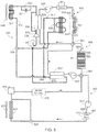
- Fig. 5 provides a schematic overview of the thermal management system of the invention, this figure illustrating thermal communications between refrigeration loop 501 and the system's three independent thermal control loops corresponding to the passenger cabin thermal control loop 503, the battery thermal control loop 505 and the drive train thermal control loop 507.
- the use of three independent thermal control circuits along with the refrigeration circuit allows the thermal management system to efficiently regulate the temperature within the passenger cabin, the battery pack and the drive train, specifically utilizing the heat generated within one subsystem to heat another subsystem.
- independent thermal control loops 503, 505 and 507 utilize the same non-gaseous, heat transfer fluid, thereby allowing the control loops to operate either independently or in series as described below.
- the heat transfer fluid is water-based, e.g., pure water or water that includes an additive such as ethylene glycol or propylene glycol, although a non-water-based, heat transfer fluid may also be used in control loops 503, 505 and 507.
- the passenger cabin includes a HVAC system, described in detail below, which provides the vehicle's occupants means for regulating cabin temperature.
- a battery pack 509 that includes at least one, and typically a plurality of batteries (e.g., tens, hundreds, or thousands of batteries), contained within a battery pack enclosure.
- the batteries are cylindrically-shaped, for example utilizing an 18650 form-factor, and are positioned within the battery pack so that the cylindrical axis of each battery is substantially perpendicular to the lower battery pack enclosure panel as well as the surface of the road.
- Cooling conduits 511 preferably deformable cooling conduits, which contain the heat transfer fluid (e.g., water), are in thermal communication with the batteries.
- the cooling conduits are aligned with the battery pack's lower panel, resulting in the coolant within the conduits flowing in a direction substantially perpendicular to the axes of the cylindrical batteries.
- the temperature of the batteries may be regulated so that they remain within their preferred operating range.
- a thermal insulator e.g., an air gap or one or more layers of a material with a low thermal conductivity
- Thermal control loop 507 is thermally coupled to drive train 513.
- Drive train 513 includes one or more motors, typically three phase alternating current (i.e., AC) motors, which are used to provide propulsive power to the vehicle.
- the portion of the drive train 513 that is thermally regulated may also include a transmission and/or a power inverter, for example as described in co-assigned U.S. Patent Application Serial No. 14/176,053, filed 8 February 2014 .
- the power inverter converts the direct current (i.e., DC) power from battery pack 509 to match the power requirements of the propulsion motor(s).
- the transmission may be a single speed, fixed gear transmission or a multi-speed transmission.
- a DC/DC converter 515 is also thermally coupled to control loop 507.
- the DC/DC converter 515 is used to convert the output of battery pack 509 to a voltage more suitable for use with the vehicle's various electrical accessories and auxiliary systems (e.g., exterior and interior lighting, audio system, navigation system, blower fans, etc.).
- thermal control loop 507 the heat transfer fluid is circulated using coolant pump 517.
- coolant pump 517 is capable of circulating the heat transfer fluid within the control loop at a flow rate of at least 15 liters per minute (lpm), both when control loop 507 is operated independently of the other thermal circuits and when control loop 507 is coupled to another control loop as described below.
- Thermal control loop 507 also includes a coolant reservoir 519.
- reservoir 519 is a high by-pass reservoir that not only deaerates the coolant within the control loop, but also provides a convenient means for adding coolant to the system.
- radiator 521 In order to passively cool the components that are thermally coupled to control circuit 507, components such as the motor, power inverter, gearbox and/or the DC/DC converter, the coolant is circulated through radiator 521. If there is insufficient air flow through radiator 521 to provide the desired level of passive cooling, for example when the vehicle is stopped or driving at slow speeds, a fan 523 may be used to force air through the radiator.
- the control loop also includes a valve 525, also referred to herein as a diverter valve, that allows radiator 521 to be decoupled, or partially decoupled, from loop 507.
- thermal control loops 503, 505 and 507 may be operated independently as illustrated in Fig. 5 , or operated in series as described and illustrated below. Accordingly, in addition to circulation pump 517 that is coupled to circuit 507, circulation pumps must also be incorporated into loops 503 and 505.
- Fig. 5 shows a single circulation pump 527 incorporated into loop 505 and a single circulation pump 529 incorporated into loop 503. It will be appreciated that more than one circulation pump may be incorporated into any of the thermal control loops.
- each circulation pump is capable of circulating the heat transfer fluid contained within the corresponding control loop at a flow rate of at least 15 liters per minute (lpm), both when operating alone and when the corresponding control loop is serially coupled to one or more other thermal control loops.
- a supplemental electric heater 533 is also thermally coupled to control loop 503, thereby providing an additional means for heating the heat transfer fluid within loop 503 and thus heating the passenger cabin to the desired level.
- refrigerant-based thermal control loop 501 serves multiple purposes and can be used in either a conventional cooling mode or in a non-conventional heat pump mode.
- loop 501 includes a compressor 535, used to compress the low temperature vapor in the refrigerant line into a high temperature vapor, and an accumulator 537 that insures that only vapor passes into compressor 535.
- Valve 539 determines the direction of flow of the refrigerant within loop 501, and thus to a degree determines whether the refrigeration system is being used in a heat pump mode or in a conventional cooling mode.
- the refrigerant passes through expansion valve 541 prior to flowing through evaporator 543, where evaporator 543 is integrated into the passenger cabin's HVAC system.
- the air that is cooled by the refrigeration system's evaporator 543 is circulated throughout the passenger cabin using fan 545.
- the refrigerant passes through heat exchanger 547, also referred to herein as a condenser/evaporator due to its dual functionality as described in detail below. It will be appreciated that in this operational mode, heat exchanger 547 is performing as an air cooled condenser.
- the system also includes a blower fan 549 that may be used to force air through heat exchanger 547 if the vehicle is traveling at a low speed, or altogether stopped, thus insuring adequate heat transfer from the refrigerant to the ambient environment.
- a blower fan 549 that may be used to force air through heat exchanger 547 if the vehicle is traveling at a low speed, or altogether stopped, thus insuring adequate heat transfer from the refrigerant to the ambient environment.
- by-pass valve 551 allows the refrigerant to by-pass expansion valve 553.
- the functionality of by-pass valve 551 and expansion valve 553 may be combined into a single electronic expansion valve.
- the refrigerant line is also coupled via expansion valve 555 to heat exchanger 557, where expansion valves 541 and 555 may be used to regulate the flow of refrigerant.
- Heat exchanger 557 which is a refrigerant/liquid exchanger, may also be referred to herein as a chiller. As shown, chiller 557 is coupled to battery thermal control loop 505, thus allowing battery pack 509 to be cooled by the heat transfer fluid within circuit 505.
- Expansion valve 555 determines, at least in part, the amount of cooling provided by the refrigeration system to battery thermal control loop 505.
- the refrigeration system may also operate in a heat pump mode by altering the flow of refrigerant using valve 539.
- the refrigerant passing through heat exchanger 559 is used to heat the heat transfer fluid within HVAC thermal control loop 503. Once heated, the heat transfer fluid is circulated through heat exchanger 531 which, in turn, heats the passenger cabin.
- Fan 545 or a different fan (not shown), is preferably used to circulate the heated air through the passenger cabin.
- the setting of by-pass valve 551 is changed so that the refrigerant can pass through expansion valve 553 prior to flowing through heat exchanger 547.
- heat exchanger 547 performs as an evaporator rather than as a condenser.
- the system also includes a by-pass valve 560 that provides an alternate refrigerant path around heat exchanger 559, thereby providing a simple means for limiting the amount of heat added to the heat transfer fluid by the heat exchanger. It will be appreciated that by using the refrigeration system as a heat pump and transferring heat from the refrigerant to the heat transfer fluid via heat exchanger 559, the cooling capacity of the AC system is increased.
- thermal management system of the invention may be configured in a variety of ways, thus allowing the thermal system to be optimized.
- thermal control loops 503, 505 and 507 are each operated independently.
- the temperature of the drive train components 513 and DC/DC converter 515 are passively cooled using radiator 521, where the amount of cooling is preferably controlled either by varying the flow rate using circulating pump 517 or varying coolant flow through radiator 521 using valve 525.
- the temperature of the coolant within battery pack thermal control circuit 505 is varied by controlling the amount of cooling provided via the refrigeration system and heat exchanger 557.
- the passenger thermal control loop 503 When the passenger thermal control loop 503 is operating in a fully independent mode, cooling is provided by the refrigeration system and evaporator 543. In this configuration, in order to heat the passenger cabin the heat transfer fluid within circuit 503 may either be heated using supplemental electric heater 533 or using the refrigeration system operating as a heat pump, where heat is transferred using heat exchanger 559.
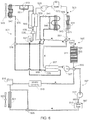
- Fig. 6 illustrates an alternate operational mode of the preferred thermal management system.
- four-way valve 561 is altered in order to combine passenger cabin thermal control loop 503 with battery pack thermal control loop 505.
- drive train thermal control loop 507 operates independently of the other two thermal control circuits.
- This operational mode provides several benefits. First, when the battery pack is running hot, this configuration allows excess battery pack heat to be transferred to the passenger cabin HVAC system, thus providing a means for heating the heat transfer fluid within circuit 503 and heat exchanger 531 without activating supplemental electric heater 533 or using the refrigeration system as a heat pump.
- thermal loop 503 when the battery pack is cold, heat from thermal loop 503 may be used to heat the batteries within pack 509 to their optimum operating range, where the heat in thermal loop 503 may be generated either by supplemental electric heater 533 or refrigeration system 501 operating as a heat pump. Note that if battery heating is provided by the refrigeration system 501 operating as a heat pump and dumping heat into the heat transfer fluid via heat exchanger 559, supplemental heater 533 becomes unnecessary. As a result, the batteries can be heated to reach their optimum operating temperature without impacting vehicle efficiency by activating the supplemental heater.
- a temperature blend door in the HVAC system may be used to prevent, or regulate, air circulated by HVAC fan 545 from flowing past heat exchanger 531 and through the passenger cabin.
- Fig. 7 illustrates another operational mode of the preferred thermal management system in which four-way valve 563 is altered in order to combine battery pack thermal control loop 505 with drive train thermal control loop 507.
- passenger cabin thermal control loop 503 operates independently of the other two thermal control circuits.
- two techniques may be used, alone or in combination, to cool battery pack 509.
- the heat transfer fluid within the thermal loop may be cooled using refrigeration system 501 and heat exchanger 557.
- the heat transfer fluid may be cooled by passing through radiator 521.
- Fig. 8 illustrates a third operational mode of the thermal management system in which both four way valves 561 and 563 are opened, thereby coupling passenger cabin control loop 503 to battery pack control loop 505 which, in turn, is coupled to drive train control loop 507.
- the battery pack may be cooled and heat transferred out of the battery pack using the refrigeration system 501, and/or heat exchanger 531, and/or radiator 521.
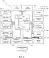
- Fig. 9 is a block diagram of an exemplary control system 900 for use with the thermal management system shown in Figs. 5-8 .
- Control system 900 includes a system controller 901.
- System controller 901 may be the same controller used to perform other vehicle functions, i.e., system controller 901 may be a vehicle system controller that may be used to control any of a variety of vehicle subsystems, e.g., navigation system, entertainment system, suspension (e.g., air suspension), battery charging, vehicle performance monitors, etc. Alternately, system controller 901 may be separate from the vehicle's system controller.
- System controller 901 includes a central processing unit (CPU) 903 and a memory 905.
- CPU central processing unit
- Memory 905 may be comprised of EPROM, EEPROM, flash memory, RAM, a solid state disk drive, a hard disk drive, or any other memory type or combination of memory types. Memory 905 may be used to store the preset operating temperature ranges for battery pack 509, drive train 513 and/or DC/DC converter 515. If the vehicle uses a touch-screen or similar display means 907 as the user interface, controller 901 may also include a graphical processing unit (GPU) 909. CPU 903 and GPU 909 may be separate or contained on a single chip set.
- GPU graphical processing unit
- Coupled to controller 901 are a plurality of temperature sensors that monitor the temperatures of various components and subsystems under the control of the thermal control system.
- battery pack 509 may include one or more temperature sensors 565 that monitor battery pack temperature.
- Other components and subsystems may also include temperature sensors, e.g., sensor 567 that monitors drive train 513.
- Temperature sensors may also be used to monitor the temperature of the heat transfer fluid within thermal control loops 503, 505 and 507, i.e., temperature sensors 569.
- Temperature/pressure sensors 570 are also preferably used to monitor the state of the refrigerant in thermal control loop 501.
- the temperature within the passenger cabin (sensor 911), the ambient temperature (sensor 913), and the sun load (sensor 915) may also be monitored.
- HVAC system interface 917 that allows the desired passenger cabin temperature to be set by the driver and/or passengers, where the desired temperature may be configured to either be set by zone or a single temperature for the entire cabin.
- the HVAC system interface 917 may be a HVAC dedicated interface, e.g., temperature control switches mounted within the passenger cabin, or may utilize a common user interface such as display interface 907.
- the thermal control system of the invention uses a variety of valves and other components to maintain each of the vehicle's subsystems (e.g., battery pack, drive train components, passenger cabin, etc.) within their desired temperature range while optimizing overall system efficiency.
- controller 901 coupled to and controlled by controller 901 are flow control valves 525, 539, 551, 560, 561 and 563; expansion valves 541, 553 and 555; compressor 535; HVAC temperature blend door 571; heat transfer fluid circulating pumps 517, 527 and 529; blower fans 523, 545 and 549; and heater 533.
- valves 1001-1004 may also be configured to provide the same operational modes as illustrated in Figs. 6 and 7 .
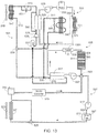
- Fig. 12 illustrates another modification of the embodiment shown in Figs. 5-8 in which four-way valve 563 is eliminated.
- drive train thermal control loop 507 always operates independently of passenger cabin thermal control loop 503 and battery pack thermal control loop 505.
- drive train thermal control loop 507 is also independent of refrigeration thermal control loop 501.
- the passenger cabin and battery pack thermal circuits may be operated independently of one another, i.e., parallel operation, or serially as shown in Fig. 6 .
- four-way valve 561 may be replaced with a pair of three-way valves as shown in Figs. 10 and 11 .
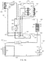
- Fig. 13 illustrates yet another modification of the embodiment shown in Figs. 5-8 in which four-way valve 561 is eliminated.
- passenger cabin thermal control loop 503 always operates independently of battery pack thermal control loop 505 and drive train thermal control loop 507.
- a supplemental heater 1301 is included in the battery thermal control loop 505, thus providing a means of actively heating the batteries within pack 509.
- the battery pack and drive train thermal circuits may be operated independently of one another, i.e., parallel operation, or serially as shown in Fig. 7 .
- four-way valve 563 may be replaced with a pair of three-way valves as shown in Figs. 10 and 11 .
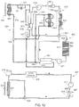
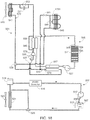
- Fig. 14 illustrates yet another modification of the embodiment shown in Figs. 5-8 in which four-way valves 561 and 563 are eliminated.
- the elimination of both four-way valves results in independent operation of the passenger cabin thermal control loop 503, the battery pack thermal control loop 505 and the drive train thermal control loop 507.
- a supplemental heater 1301 is included in the battery thermal control loop 505 in order to provide a means for actively heating the batteries as deemed necessary.
- a supplemental heater 1301 is incorporated into the battery thermal control loop 505.
- Figs. 15 and 16 illustrate an alternate approach of active battery heating, based on Figs. 13 and 14 , which utilizes heat exchanger 559 and the refrigeration loop 501 rather than supplemental heater 1301 to heat the heat transfer fluid within the battery loop.
- supplemental heater 1301 may also be added to the embodiments shown in Figs. 15 and 16 .
- passenger cabin heating can be provided using supplemental heater 533 as shown in Figs. 15 and 16 , preferably an electric air heater 1701, e.g., incorporated into evaporator assembly 543, is used for passenger cabin heating as shown in Figs. 17 and 18 .
Landscapes
- Engineering & Computer Science (AREA)
- Mechanical Engineering (AREA)
- Life Sciences & Earth Sciences (AREA)
- Thermal Sciences (AREA)
- Physics & Mathematics (AREA)
- Transportation (AREA)
- Power Engineering (AREA)
- Sustainable Energy (AREA)
- Sustainable Development (AREA)
- Manufacturing & Machinery (AREA)
- General Chemical & Material Sciences (AREA)
- Electrochemistry (AREA)
- Chemical Kinetics & Catalysis (AREA)
- Chemical & Material Sciences (AREA)
- Air-Conditioning For Vehicles (AREA)
- Electric Propulsion And Braking For Vehicles (AREA)
Description
- The present invention relates generally to electric vehicles and, more particularly, to a thermally efficient and configurable thermal management system.
- In response to the demands of consumers who are driven both by ever-escalating fuel prices and the dire consequences of global warming, the automobile industry is slowly starting to embrace the need for ultra-low emission, high efficiency cars. While some within the industry are attempting to achieve these goals by engineering more efficient internal combustion engines, others are incorporating hybrid or all-electric drive trains into their vehicle line-ups. To meet consumer expectations, however, the automobile industry must not only achieve a greener drive train, but must do so while maintaining reasonable levels of performance, range, reliability, and cost.
- Electric vehicles, due to their reliance on rechargeable batteries, require a relatively sophisticated thermal management system to insure that the batteries remain within their desired operating temperature range. Furthermore, in addition to controlling battery temperature the thermal management system must also be capable of heating and cooling the passenger cabin while not unduly affecting the vehicle's overall operating efficiency.
- A variety of approaches have been taken to try and meet these goals. For example,
U.S. Patent No. 6,360,835 discloses a thermal management system for use with a fuel-cell-powered vehicle, the system utilizing both low and high temperature heat transfer circuits that share a common heat transfer medium, the dual circuits required to adequately cool the vehicle's exothermic components and heat the vehicle's endothermic components. -
U.S. Patent No. 7,789,176 discloses a thermal management system that utilizes multiple cooling loops and a single heat exchanger. In an exemplary embodiment, one cooling loop is used to cool the energy storage system, a second cooling loop corresponds to the HVAC subsystem, and a third cooling loop corresponds to the drive motor cooling system. The use of a heater coupled to the first cooling loop is also disclosed, the heater providing a means for insuring that the batteries are warm enough during initial vehicle operation or when exposed to very low ambient temperatures. -
U.S. Patent No. 8,336,319 discloses an EV dual mode thermal management system designed to optimize efficiency between two coolant loops, the first cooling loop in thermal communication with the vehicle's batteries and the second cooling loop in thermal communication with at least one drive train component such as an electric motor or an inverter. The disclosed system uses a dual mode valve system to configure the thermal management system between a first mode and a second mode of operation, where in the first mode the two cooling loops operate in parallel and in the second mode the two cooling loops operate in series. DocumentUS 2014/0041826 A1 discloses a multi mode thermal management system. It does not show: - a first refrigerant-fluid heat exchanger (559) coupled to a passenger cabin thermal control loop (503), said passenger cabin thermal control loop containing said heat transfer fluid, wherein a third circulation pump (529) circulates said heat transfer fluid within said passenger cabin thermal control loop, and wherein said passenger cabin thermal control loop provides temperature control of a vehicle passenger cabin;
- a liquid-air heat exchanger (531), wherein said heat transfer fluid of said passenger cabin thermal control loop circulates through said liquid-air heat exchanger, wherein
- when said refrigerant-based thermal control loop (501) operates in said cooling mode said refrigerant valve (539) is configured in said first mode directing said refrigerant also through said third expansion valve (555) and through said second refrigerant-fluid heat exchanger (557), and
- a first valve assembly comprising a first valve assembly four way valve (563) or a first valve assembly pair of three-way valves (1003/1004), wherein said battery thermal control loop (505) operates in parallel with and independent of said drive train thermal control loop (507) when said first valve assembly is configured in a first valve assembly first mode, and wherein said battery thermal control loop (505) is serially coupled to said drive train thermal control loop (507) when said first valve assembly is configured in a first valve assembly second mode;
- Although the prior art discloses numerous techniques for maintaining the temperature of the battery pack and other vehicle subsystems, an improved thermal management system is needed that efficiently controls the temperature of each of the vehicle's thermal systems while optimizing overall vehicle operating efficiency. The present invention provides such a thermal management system.
- The present invention provides a vehicle thermal management system according to claim 1. In at least one embodiment, the system includes (i) a battery thermal control loop comprising a first circulation pump that circulates a heat transfer fluid within the battery thermal control loop, and where the battery thermal control loop is thermally coupled to a vehicle battery pack; (ii) a drive train control loop comprising a second circulation pump that circulates the heat transfer fluid within the drive train control loop, and where the drive train control loop is thermally coupled to at least one drive train component; (iii) a first valve assembly comprising a first valve assembly four way valve or a first valve assembly pair of three-way valves, where the battery thermal control loop operates in parallel with and independent of the drive train thermal control loop when the first valve assembly is configured in a first valve assembly first mode, and where the battery thermal control loop is serially coupled to the drive train thermal control loop when the valve assembly is configured in a first valve assembly second mode; (iv) a refrigerant-based thermal control loop comprised of a refrigerant, a compressor, and a condenser/evaporator; (v) a refrigerant-air heat exchanger coupled to the refrigerant-based thermal control loop by a first expansion valve, where the refrigerant-air heat exchanger is thermally coupled to a vehicle HVAC system; (vii) a refrigerant valve operable in at least two modes; and (vii) a refrigerant-fluid heat exchanger coupled to a thermal control loop, where the refrigerant valve in a first mode directs the refrigerant through the refrigerant-air heat exchanger and the first expansion valve, and where the refrigerant valve in a second mode directs the refrigerant through the refrigerant-fluid heat exchanger which, in turn, heats the heat transfer fluid within the thermal control loop. In one aspect, the thermal control loop may be comprised of the battery thermal control loop in which case the refrigerant-fluid heat exchanger is coupled to the battery thermal control loop. The system may further include a second refrigerant-fluid heat exchanger coupled to the refrigerant-based thermal control loop by a second expansion valve, where the second refrigerant-fluid heat exchanger is thermally coupled to the battery thermal control loop. In another aspect, the battery thermal control loop may include a supplemental electric heater configured to heat the heat transfer fluid of the battery thermal control loop when electrical power is connected to the supplemental electric heater. In another aspect, the system may further include a passenger cabin thermal control loop comprising a third circulation pump, where the third circulation pump circulates the heat transfer fluid within the passenger cabin thermal control loop, and where the passenger cabin thermal control loop provides temperature control of a vehicle passenger cabin. The thermal control loop may be comprised of the passenger cabin thermal control loop in which case the refrigerant-fluid heat exchanger is coupled to the passenger cabin thermal control loop. The system may further include a second refrigerant-fluid heat exchanger coupled to the refrigerant-based thermal control loop by a second expansion valve, where the second refrigerant-fluid heat exchanger is thermally coupled to the battery thermal control loop. The system may further include a second valve assembly, where the second valve assembly may be comprised of a second valve assembly four way valve or a second valve assembly pair of three-way valves, where the passenger cabin thermal control loop operates in parallel with and independent of the battery thermal control loop when the second valve assembly is configured in a second valve assembly first mode, and where the passenger cabin thermal control loop is serially coupled to the battery thermal control loop when the second valve assembly is configured in a second valve assembly second mode. The passenger cabin thermal control loop may further include a liquid-air heat exchanger, where the heat transfer fluid of the passenger cabin thermal control loop circulates through the liquid-air heat exchanger. The passenger cabin thermal control loop may further include an electric heater configured to heat the heat transfer fluid of the passenger cabin thermal control loop when electrical power is connected to the electric heater. In another aspect, the system may further include (i) a by-pass valve, and (ii) a third expansion valve interposed between the refrigerant-fluid heat exchanger and the condenser/evaporator, wherein when the refrigerant valve is in the first mode the by-pass valve is configured to allow the refrigerant in the refrigerant-based thermal control loop to by-pass the third expansion valve, and wherein when the refrigerant valve is in the second mode the by-pass valve is configured to allow the refrigerant in the refrigerant-based thermal control loop to flow through the third expansion valve. The by-pass valve and the third expansion valve may be combined in an electronic expansion valve. In another aspect, system may further include a second refrigerant by-pass valve, where the second refrigerant by-pass valve in a first mode of operation couples the refrigerant-fluid heat exchanger to the refrigerant-based thermal control loop, and where the second refrigerant by-pass valve in a second mode of operation decouples the refrigerant-fluid heat exchanger from the refrigerant-based thermal control loop.
- In another embodiment, the system includes (i) a passenger cabin thermal control loop comprising a first circulation pump that circulates a heat transfer fluid within the passenger cabin thermal control loop, and where the passenger cabin thermal control loop provides temperature control of a vehicle passenger cabin; (ii) a battery thermal control loop comprising a second circulation pump that circulates the heat transfer fluid within the battery thermal control loop, and where the battery thermal control loop is thermally coupled to a vehicle battery pack; (iii) a drive train control loop comprising a third circulation pump that circulates the heat transfer fluid within the drive train control loop, and where the drive train control loop is thermally coupled to at least one drive train component; (iv) a first valve assembly, where the passenger cabin thermal control loop operates in parallel with and independent of the battery thermal control loop when the first valve assembly is configured in a first valve assembly first mode, and where the passenger cabin thermal control loop is serially coupled to the battery thermal control loop when the first valve assembly is configured in a first valve assembly second mode; and (v) a second valve assembly, where the battery thermal control loop operates in parallel with and independent of the drive train thermal control loop when the second valve assembly is configured in a second valve assembly first mode, and where the battery thermal control loop is serially coupled to the drive train thermal control loop when the second valve assembly is configured in a second valve assembly second mode. The passenger cabin thermal control loop may include a liquid-air heat exchanger, where the heat transfer fluid of the passenger cabin thermal control loop circulates through the liquid-air heat exchanger. The passenger cabin thermal control loop may also include an electric heater configured to heat the heat transfer fluid within the passenger cabin thermal control loop when electrical power is connected to the electric heater. In another aspect, the first valve assembly may be comprised of a four-way valve, where in a first mode the four-way valve couples a first portion of the passenger cabin thermal control loop to a second portion of the passenger cabin thermal control loop and couples a first portion of the battery thermal control loop to a second portion of the battery thermal control loop, and where in a second mode the four-way valve couples the first portion of the passenger cabin thermal control loop to the second portion of the battery thermal control loop and couples the first portion of the battery thermal control loop to the second portion of the passenger cabin thermal control loop. In another aspect, the first valve assembly may be comprised of a first three-way valve and a second three-way valve, where in a first mode the first three-way valve couples a first portion of the passenger cabin thermal control loop to a second portion of the passenger cabin thermal control loop, where in the second mode the first three-way valve couples a first portion of the battery thermal control loop to a second portion of the battery thermal control loop, where in a second mode the first three-way valve couples the first portion of the passenger cabin thermal control loop to the second portion of the battery thermal control loop, and where in the second mode the second three-way valve couples the first portion of the battery thermal control loop to the second portion of the passenger cabin thermal control loop. In another aspect, the second valve assembly may be comprised of a four-way valve, where in a first mode the four-way valve couples a first portion of the battery thermal control loop to a second portion of the battery thermal control loop and couples a first portion of the drive train thermal control loop to a second portion of the drive train thermal control loop, and where in a second mode the four-way valve couples the first portion of the battery thermal control loop to the second portion of the drive train thermal control loop and couples the first portion of the drive train thermal control loop to the second portion of the battery thermal control loop. In another aspect, the second valve assembly may be comprised of a first three-way valve and a second three-way valve, where in a first mode the first three-way valve couples a first portion of the battery thermal control loop to a second portion of the battery thermal control loop, where in the second mode the first three-way valve couples a first portion of the drive train thermal control loop to a second portion of the drive train thermal control loop, where in a second mode the first three-way valve couples the first portion of the battery thermal control loop to the second portion of the drive train thermal control loop, and where in the second mode the second three-way valve couples the first portion of the drive train thermal control loop to the second portion of the battery thermal control loop. In another aspect, the system may include (i) a refrigerant-based thermal control loop comprised of a refrigerant, a compressor, and a condenser/evaporator; and (ii) a refrigerant-air heat exchanger coupled to the refrigerant-based thermal control loop by a first expansion valve, where the refrigerant-air heat exchanger is thermally coupled to a vehicle HVAC system. The refrigerant-based thermal control loop may include a refrigerant-fluid heat exchanger coupled to the refrigerant-based thermal control loop by a second expansion valve, where the refrigerant-fluid heat exchanger is thermally coupled to the battery thermal control loop. The refrigerant-based thermal control loop may further include a (i) a refrigerant valve operable in at least two modes; and (ii) a refrigerant-fluid heat exchanger coupled to the passenger cabin thermal control loop, where the refrigerant valve in a first mode directs the refrigerant through the refrigerant-air heat exchanger and the first expansion valve, and where the refrigerant valve in a second mode directs the refrigerant through the refrigerant-fluid heat exchanger which, in turn, heats the heat transfer fluid within the passenger cabin thermal control loop. The refrigerant-based thermal control loop may further include a (i) a by-pass valve; and (ii) a second expansion valve interposed between the refrigerant-fluid heat exchanger and the condenser/evaporator, where when the refrigerant valve is in the first mode the by-pass valve is configured to allow the refrigerant in the refrigerant-based thermal control loop to by-pass the second expansion valve, and where when the refrigerant valve is in the second mode the by-pass valve is configured to allow the refrigerant in the refrigerant-based thermal control loop to flow through the second expansion valve. The by-pass valve and the second expansion valve may be combined into a single electronic expansion valve. The refrigerant-based thermal control loop may further include a secondary refrigerant by-pass valve, where the secondary refrigerant by-pass valve in a first operational mode couples the refrigerant-fluid heat exchanger to the refrigerant-based thermal control loop, and where the secondary refrigerant by-pass valve in a second operational mode decouples the refrigerant-fluid heat exchanger from the refrigerant-based thermal control loop. The passenger cabin thermal control loop further may further include a liquid-air heat exchanger, where the heat transfer fluid of the passenger cabin thermal control loop circulates through the liquid-air heat exchanger. A supplemental electric heater may be configured to heat the heat transfer fluid of the passenger cabin thermal control loop when electrical power is connected to the supplemental electric heater.
- In another embodiment, the system includes (i) a passenger cabin thermal control loop comprising a first circulation pump and a liquid-air heat exchanger, where the first circulation pump circulates a first heat transfer fluid within the passenger cabin thermal control loop and through the liquid-air heat exchanger, and where the passenger cabin thermal control loop provides temperature control of a vehicle passenger cabin; (ii) a battery thermal control loop comprising a second circulation pump that circulates a second heat transfer fluid within the battery thermal control loop, where the battery thermal control loop is thermally coupled to a vehicle battery pack, and where the passenger cabin thermal control loop operates in parallel with and independent of the battery thermal control loop; (iii) a drive train control loop comprising a third circulation pump that circulates the second heat transfer fluid within the drive train control loop, where the drive train control loop is thermally coupled to at least one drive train component, and where the passenger cabin thermal control loop operates in parallel with and independent of the drive train thermal control loop; (iv) a valve assembly, where the battery thermal control loop operates in parallel with and independent of the drive train thermal control loop when the valve assembly is configured in a first mode, and where the battery thermal control loop is serially coupled to the drive train thermal control loop when the valve assembly is configured in a second mode; (v) a refrigerant-based thermal control loop comprised of a refrigerant, a compressor, and a condenser/evaporator; (vi) a refrigerant-air heat exchanger coupled to the refrigerant-based thermal control loop by a first expansion valve, where the refrigerant-air heat exchanger is thermally coupled to a vehicle HVAC system; (vii) a refrigerant valve operable in at least two modes; and (viii) a refrigerant-fluid heat exchanger coupled to the passenger cabin thermal control loop, where the refrigerant valve in a first mode directs the refrigerant through the refrigerant-air heat exchanger and the first expansion valve, and where the refrigerant valve in a second mode directs the refrigerant through the refrigerant-fluid heat exchanger which, in turn, heats the first heat transfer fluid within the passenger cabin thermal control loop. In another aspect, the refrigerant-based thermal control loop may further include a second refrigerant-fluid heat exchanger coupled to the refrigerant-based thermal control loop by a second expansion valve, where the second refrigerant-fluid heat exchanger is thermally coupled to the battery thermal control loop. In another aspect, the system may include (i) a refrigerant by-pass valve; and (ii) a second expansion valve interposed between the refrigerant-fluid heat exchanger and the condenser/evaporator, where when the refrigerant valve is in the first mode the refrigerant by-pass valve is configured to allow the refrigerant in the refrigerant-based thermal control loop to by-pass the second expansion valve, and where when the refrigerant valve is in the second mode the refrigerant by-pass valve is configured to allow the refrigerant in the refrigerant-based thermal control loop to flow through the second expansion valve. The by-pass valve and the second expansion valve may be combined into a single electronic expansion valve. In another aspect, the refrigerant-based thermal control loop may further include a refrigerant by-pass valve, where the refrigerant by-pass valve in a first operational mode couples the refrigerant-fluid heat exchanger to the refrigerant-based thermal control loop, and where the secondary refrigerant by-pass valve in a second operational mode decouples the refrigerant-fluid heat exchanger from the refrigerant-based thermal control loop. In another aspect, the passenger cabin thermal control loop may further include a supplemental electric heater configured to heat the first heat transfer fluid within the passenger cabin thermal control loop when electrical power is connected to the supplemental electric heater. In another aspect, the battery thermal control loop may further include a supplemental electric heater configured to heat the second heat transfer fluid within the battery thermal control loop when electrical power is connected to the supplemental electric heater. In another aspect, the valve assembly may be comprised of a four-way valve, where in a first mode the four-way valve couples a first portion of the battery thermal control loop to a second portion of the battery thermal control loop and couples a first portion of the drive train thermal control loop to a second portion of the drive train thermal control loop, and where in a second mode the four-way valve couples the first portion of the battery thermal control loop to the second portion of the drive train thermal control loop and couples the first portion of the drive train thermal control loop to the second portion of the battery thermal control loop. In another aspect, the valve assembly may be comprised of a first three-way valve and a second three-way valve, where in a first mode the first three-way valve couples a first portion of the battery thermal control loop to a second portion of the battery thermal control loop, where in the second mode the first three-way valve couples a first portion of the drive train thermal control loop to a second portion of the drive train thermal control loop, where in a second mode the first three-way valve couples the first portion of the battery thermal control loop to the second portion of the drive train thermal control loop, and where in the second mode the second three-way valve couples the first portion of the drive train thermal control loop to the second portion of the battery thermal control loop.
- In another embodiment, the system includes (i) a passenger cabin thermal control loop comprising a first circulation pump and a liquid-air heat exchanger, where the first circulation pump circulates a first heat transfer fluid within the passenger cabin thermal control loop and through the liquid-air heat exchanger, and where the passenger cabin thermal control loop provides temperature control of a vehicle passenger cabin; (ii) a battery thermal control loop comprising a second circulation pump that circulates a second heat transfer fluid within the battery thermal control loop, where the battery thermal control loop is thermally coupled to a vehicle battery pack, and where the passenger cabin thermal control loop operates in parallel with and independent of the battery thermal control loop; (iii) a drive train control loop comprising a third circulation pump that circulates the second heat transfer fluid within the drive train control loop, where the drive train control loop is thermally coupled to at least one drive train component, and where the passenger cabin thermal control loop operates in parallel with and independent of the drive train thermal control loop; (iv) a valve assembly, where the battery thermal control loop operates in parallel with and independent of the drive train thermal control loop when the valve assembly is configured in a first mode, and where the battery thermal control loop is serially coupled to the drive train thermal control loop when the valve assembly is configured in a second mode; (v) a refrigerant-based thermal control loop comprised of a refrigerant, a compressor, and a condenser/evaporator; (vi) a refrigerant-air heat exchanger coupled to the refrigerant-based thermal control loop by a first expansion valve, where the refrigerant-air heat exchanger is thermally coupled to a vehicle HVAC system; (vii) a refrigerant valve operable in at least two modes; and (viii) a refrigerant-fluid heat exchanger coupled to the battery thermal control loop, where the refrigerant valve in a first mode directs the refrigerant through the refrigerant-air heat exchanger and the first expansion valve, and where the refrigerant valve in a second mode directs the refrigerant through the refrigerant-fluid heat exchanger which, in turn, heats the second heat transfer fluid within the battery thermal control loop. In another aspect, the refrigerant-based thermal control loop may further include a second refrigerant-fluid heat exchanger coupled to the refrigerant-based thermal control loop by a second expansion valve, where the second refrigerant-fluid heat exchanger is thermally coupled to the battery thermal control loop. In another aspect, the system may include (i) a refrigerant by-pass valve; and (ii) a second expansion valve interposed between the refrigerant-fluid heat exchanger and the condenser/evaporator, where when the refrigerant valve is in the first mode the refrigerant by-pass valve is configured to allow the refrigerant in the refrigerant-based thermal control loop to by-pass the second expansion valve, and where when the refrigerant valve is in the second mode the refrigerant by-pass valve is configured to allow the refrigerant in the refrigerant-based thermal control loop to flow through the second expansion valve. The by-pass valve and the second expansion valve may be combined into a single electronic expansion valve. In another aspect, the refrigerant-based thermal control loop may further include a refrigerant by-pass valve, where the refrigerant by-pass valve in a first operational mode couples the refrigerant-fluid heat exchanger to the refrigerant-based thermal control loop, and where the secondary refrigerant by-pass valve in a second operational mode decouples the refrigerant-fluid heat exchanger from the refrigerant-based thermal control loop. In another aspect, the passenger cabin thermal control loop may further include a supplemental electric heater configured to heat the first heat transfer fluid within the passenger cabin thermal control loop when electrical power is connected to the supplemental electric heater. In another aspect, the valve assembly may be comprised of a four-way valve, where in a first mode the four-way valve couples a first portion of the battery thermal control loop to a second portion of the battery thermal control loop and couples a first portion of the drive train thermal control loop to a second portion of the drive train thermal control loop, and where in a second mode the four-way valve couples the first portion of the battery thermal control loop to the second portion of the drive train thermal control loop and couples the first portion of the drive train thermal control loop to the second portion of the battery thermal control loop. In another aspect, the valve assembly may be comprised of a first three-way valve and a second three-way valve, where in a first mode the first three-way valve couples a first portion of the battery thermal control loop to a second portion of the battery thermal control loop, where in the second mode the first three-way valve couples a first portion of the drive train thermal control loop to a second portion of the drive train thermal control loop, where in a second mode the first three-way valve couples the first portion of the battery thermal control loop to the second portion of the drive train thermal control loop, and where in the second mode the second three-way valve couples the first portion of the drive train thermal control loop to the second portion of the battery thermal control loop.
- In another embodiment, the system includes (i) a battery thermal control loop comprising a first circulation pump that circulates a heat transfer fluid within the battery thermal control loop, and where the battery thermal control loop is thermally coupled to a vehicle battery pack; (ii) a drive train control loop comprising a third circulation pump that circulates the heat transfer fluid within the drive train control loop, and where the drive train control loop is thermally coupled to at least one drive train component; (iii) a valve assembly, where the battery thermal control loop operates in parallel with and independent of the drive train thermal control loop when the valve assembly is configured in a first mode, and where the battery thermal control loop is serially coupled to the drive train thermal control loop when the valve assembly is configured in a second mode; (iv) a refrigerant-based thermal control loop comprised of a refrigerant, a compressor, and a condenser/evaporator; (v) a refrigerant-air heat exchanger coupled to the refrigerant-based thermal control loop by a first expansion valve, where the refrigerant-air heat exchanger is thermally coupled to a vehicle HVAC system; (vii) a refrigerant valve operable in at least two modes; and (vii) a refrigerant-fluid heat exchanger coupled to the battery thermal control loop, where the refrigerant valve in a first mode directs the refrigerant through the refrigerant-air heat exchanger and the first expansion valve, and where the refrigerant valve in a second mode directs the refrigerant through the refrigerant-fluid heat exchanger which, in turn, heats the heat transfer fluid within the battery thermal control loop. In another aspect, the refrigerant-based thermal control loop may further include a second refrigerant-fluid heat exchanger coupled to the refrigerant-based thermal control loop by a second expansion valve, where the second refrigerant-fluid heat exchanger is thermally coupled to the battery thermal control loop. In another aspect, the system may include (i) a refrigerant by-pass valve; and (ii) a second expansion valve interposed between the refrigerant-fluid heat exchanger and the condenser/evaporator, where when the refrigerant valve is in the first mode the refrigerant by-pass valve is configured to allow the refrigerant in the refrigerant-based thermal control loop to by-pass the second expansion valve, and where when the refrigerant valve is in the second mode the refrigerant by-pass valve is configured to allow the refrigerant in the refrigerant-based thermal control loop to flow through the second expansion valve. The by-pass valve and the second expansion valve may be combined into a single electronic expansion valve. In another aspect, the refrigerant-based thermal control loop may further include a refrigerant by-pass valve, where the refrigerant by-pass valve in a first operational mode couples the refrigerant-fluid heat exchanger to the refrigerant-based thermal control loop, and where the secondary refrigerant by-pass valve in a second operational mode decouples the refrigerant-fluid heat exchanger from the refrigerant-based thermal control loop. In another aspect, the system may further include a supplemental electric heater thermally coupled to the vehicle's HVAC system. In another aspect, the valve assembly may be comprised of a four-way valve, where in a first mode the four-way valve couples a first portion of the battery thermal control loop to a second portion of the battery thermal control loop and couples a first portion of the drive train thermal control loop to a second portion of the drive train thermal control loop, and where in a second mode the four-way valve couples the first portion of the battery thermal control loop to the second portion of the drive train thermal control loop and couples the first portion of the drive train thermal control loop to the second portion of the battery thermal control loop. In another aspect, the valve assembly may be comprised of a first three-way valve and a second three-way valve, where in a first mode the first three-way valve couples a first portion of the battery thermal control loop to a second portion of the battery thermal control loop, where in the second mode the first three-way valve couples a first portion of the drive train thermal control loop to a second portion of the drive train thermal control loop, where in a second mode the first three-way valve couples the first portion of the battery thermal control loop to the second portion of the drive train thermal control loop, and where in the second mode the second three-way valve couples the first portion of the drive train thermal control loop to the second portion of the battery thermal control loop.
- In any of the above embodiments, the system may include a radiator coupled to the drive train thermal loop. The system may include a diverter valve, where the diverter valve in a first position couples the radiator to the drive train thermal loop and allows at least a portion of the heat transfer fluid to flow through the radiator, and where the diverter valve in a second position decouples the radiator from the drive train thermal loop and allows the heat transfer fluid within the drive train thermal loop to bypass the radiator. In the first position, the diverter valve may be configured to allow a second portion of the heat transfer fluid to bypass the radiator. In a third position, the diverter valve may be configured to couple the radiator to the drive train thermal loop and allow the heat transfer fluid to flow through the radiator while preventing the second portion of the heat transfer fluid from bypassing the radiator. A fan may be included that is configured to force air through the radiator.
- In any of the above embodiments, the vehicle battery pack may include a plurality of batteries and a plurality of cooling conduits in thermal communication with the plurality of batteries, where the heat transfer fluid flows through the plurality of cooling conduits. The vehicle drive train component may be selected from the group consisting of a motor, a gearbox, and a power inverter. A DC/DC converter may be thermally coupled to the drive train control loop.
- In any of the above embodiments, the heat transfer fluid may be selected from the group of fluids consisting of water and water with an additive, where the additive may be selected from the group consisting of ethylene glycol and propylene glycol.
- In any of the above embodiments, the system may include a coolant reservoir, where the heat transfer fluid within the drive train thermal loop flows into and out of the coolant reservoir.
- A further understanding of the nature and advantages of the present invention may be realized by reference to the remaining portions of the specification and the drawings.
- It should be understood that the accompanying figures are only meant to illustrate, not limit, the scope of the invention and should not be considered to be to scale. Additionally, the same reference label on different figures should be understood to refer to the same component or a component of similar functionality.
-
Fig. 1 provides a perspective view of a battery pack and the vehicle chassis to which it is to be mounted; -
Fig. 2 illustrates an exemplary battery pack cooling system in accordance with the prior art; -
Fig. 3 illustrates an alternate battery pack cooling system in accordance with the prior art; -
Fig. 4 illustrates an alternate battery pack cooling system in accordance with the prior art, the illustrated system utilizing both a radiator and a heat exchanger as described relative toFigs. 2 and3 , respectively; -
Fig. 5 schematically illustrates a preferred embodiment of the thermal management system of the invention; -
Fig. 6 illustrates an alternate configuration of the preferred thermal management system shown inFig. 5 in which the passenger cabin thermal control loop is coupled to the battery pack thermal control loop; -
Fig. 7 illustrates an alternate configuration of the preferred thermal management system shown inFig. 5 in which the battery pack thermal control loop is coupled to the drive train thermal control loop; -
Fig. 8 illustrates an alternate configuration of the preferred thermal management system shown inFig. 5 in which the passenger cabin thermal control loop is coupled to the battery pack thermal control loop which, in turn, is coupled to the drive train thermal control loop; -
Fig. 9 provides a block diagram of an exemplary control system for use with the thermal management system shown inFigs. 5-8 ; -
Fig. 10 illustrates a modification of the preferred thermal management system shown inFig. 5 in which each four-way valves is replaced with a pair of three-way valves; -
Fig. 11 illustrates the thermal management system shown inFig. 10 , reconfigured to serially couple the passenger cabin thermal control loop to the battery pack thermal control loop which, in turn, is coupled to the drive train thermal control loop; -
Fig. 12 illustrates a modification of the preferred thermal management system shown inFigs. 5-8 in which one of the four-way valves is eliminated, thereby causing the drive train thermal control loop to operate independently of the passenger cabin thermal control loop and the battery pack thermal control loop; -
Fig. 13 illustrates a modification of the preferred thermal management system shown inFigs. 5-8 in which one of the four-way valves is eliminated, thereby causing the passenger cabin thermal control loop to operate independently of the battery pack thermal control loop and the drive train thermal control loop; -
Fig. 14 illustrates a modification of the preferred thermal management system shown inFigs. 5-8 in which both four-way valves are eliminated, thereby causing independent operation of the passenger cabin thermal control loop, the battery pack thermal control loop and the drive train thermal control loop; -
Fig. 15 illustrates a modification of the thermal management system shown inFig. 13 in which the refrigeration system is used as a heat pump to heat the battery pack thermally coupled to the battery thermal control loop; -
Fig. 16 illustrates a modification of the thermal management system shown inFig. 14 in which the refrigeration system is used as a heat pump to heat the battery pack thermally coupled to the battery thermal control loop; -
Fig. 17 illustrates a modification of the thermal management system shown inFig. 15 utilizing an alternate passenger cabin heating system; and -
Fig. 18 illustrates a modification of the thermal management system shown inFig. 16 utilizing an alternate passenger cabin heating system. - As used herein, the singular forms "a", "an" and "the" are intended to include the plural forms as well, unless the context clearly indicates otherwise. The terms "comprises", "comprising", "includes", and/or "including", as used herein, specify the presence of stated features, steps, operations, elements, and/or components, but do not preclude the presence or addition of one or more other features, steps, operations, elements, components, and/or groups thereof. As used herein, the term "and/or" and the symbol "/" are meant to include any and all combinations of one or more of the associated listed items. Additionally, while the terms first, second, etc. may be used herein to describe various steps or calculations, these steps or calculations should not be limited by these terms, rather these terms are only used to distinguish one step or calculation from another. For example, a first calculation could be termed a second calculation, and, similarly, a first step could be termed a second step, without departing from the scope of this disclosure.
- In the following text, the terms "battery", "cell", and "battery cell" may be used interchangeably and may refer to any of a variety of different battery configurations and chemistries. Typical battery chemistries include, but are not limited to, lithium ion, lithium ion polymer, nickel metal hydride, nickel cadmium, nickel hydrogen, nickel zinc, and silver zinc. The term "battery pack" as used herein refers to an assembly of one or more batteries electrically interconnected to achieve the desired voltage and capacity, where the battery assembly is typically contained within an enclosure. The terms "electric vehicle" and "EV" may be used interchangeably and may refer to an all-electric vehicle, a plug-in hybrid vehicle, also referred to as a PHEV, or a hybrid vehicle, also referred to as a HEV, where a hybrid vehicle utilizes multiple sources of propulsion including an electric drive system. The terms "thermal control circuit" and "thermal control loop" may be used interchangeably.
-
Fig. 1 provides a perspective view of abattery pack 101 configured to be mounted undervehicle chassis 103. It should be understood that the present invention is not limited to a specific battery pack mounting scheme, battery pack size, or battery pack configuration. -
Fig. 2 illustrates an exemplary batterythermal management system 200 in accordance with the prior art. Insystem 200, the temperature of the batteries withinbattery pack 101 is controlled by pumping a thermal transfer medium, e.g., a liquid coolant, through a plurality of coolingconduits 201 integrated intobattery pack 101.Conduits 201, which are fabricated from a material with a relatively high thermal conductivity, are positioned withinpack 101 in order to optimize thermal communication between the individual batteries, not shown, and the conduits, thereby allowing the temperature of the batteries to be regulated by regulating the flow of coolant withinconduits 201 and/or regulating the transfer of heat from the coolant to another temperature control system. In the illustrated embodiment, the coolant withinconduits 201 is pumped through aradiator 203 using apump 205. Ablower fan 207 may be used to force air throughradiator 203, for example when the car is stationary or moving at low speeds, thus insuring that there is an adequate transfer of thermal energy from the coolant to the ambient environment.System 200 may also include aheater 209, e.g., a PTC heater, that may be used to heat the coolant withinconduits 201, and thus heat the batteries withinpack 101. -
Fig. 3 illustrates an alternate battery packthermal management system 300. Insystem 300 the coolant withinconduits 201 is coupled to a secondarythermal management system 301 via aheat exchanger 303. Preferablythermal management system 301 is a refrigeration system and as such, includes acompressor 305 to compress the low temperature vapor inrefrigerant line 307 into a high temperature vapor and acondenser 309 in which a portion of the captured heat is dissipated. After passing throughcondenser 309, the refrigerant changes phases from vapor to liquid, the liquid remaining at a temperature below the saturation temperature at the prevailing pressure. The refrigerant then passes through adryer 311 that removes moisture from the condensed refrigerant. Afterdryer 311,refrigerant line 307 is coupled toheat exchanger 303 viathermal expansion valve 313 which controls the flow rate of refrigerant intoheat exchanger 303. Additionally, in the illustrated system ablower fan 315 is used in conjunction withcondenser 309 to improve system efficiency. - In a typical vehicle configuration,
thermal management system 301 is also coupled to the vehicle's heating, ventilation and air conditioning (HVAC) system. In such a system, in addition to couplingrefrigerant line 307 toheat exchanger 303,line 307 may also be coupled to theHVAC evaporator 317. Athermal expansion valve 319 is preferably used to control refrigerant flow rate into the evaporator. A heater, for example aPTC heater 321 integrated intoevaporator 317, may be used to provide warm air to the passenger cabin. In a conventional HVAC system, one ormore fans 323 are used to circulate air throughout the passenger cabin, where the circulating air may be ambient air, air cooled viaevaporator 317, or air heated byheater 321. - In some electric vehicles, battery pack cooling is accomplished using a combination of a radiator such as that shown in
Fig. 2 , and a heat exchanger such as that shown inFig. 3 .Fig. 4 illustrates such a conventional cooling system. Insystem 400, the coolant passing throughbattery pack 101 viaconduits 201 may be directed through eitherradiator 401 orheat exchanger 303.Valve 403 controls the flow of coolant throughradiator 401. Preferably ablower fan 405 is included insystem 400 as shown, thus providing means for forcing air through the radiator when necessary, for example when the car is stationary. -
Fig. 5 provides a schematic overview of the thermal management system of the invention, this figure illustrating thermal communications betweenrefrigeration loop 501 and the system's three independent thermal control loops corresponding to the passenger cabinthermal control loop 503, the batterythermal control loop 505 and the drive trainthermal control loop 507. The use of three independent thermal control circuits along with the refrigeration circuit allows the thermal management system to efficiently regulate the temperature within the passenger cabin, the battery pack and the drive train, specifically utilizing the heat generated within one subsystem to heat another subsystem. In the preferred embodiment shown inFig. 5 , independentthermal control loops control loops - The passenger cabin includes a HVAC system, described in detail below, which provides the vehicle's occupants means for regulating cabin temperature. Coupled to battery
thermal control loop 505 is abattery pack 509 that includes at least one, and typically a plurality of batteries (e.g., tens, hundreds, or thousands of batteries), contained within a battery pack enclosure. In at least one configuration the batteries are cylindrically-shaped, for example utilizing an 18650 form-factor, and are positioned within the battery pack so that the cylindrical axis of each battery is substantially perpendicular to the lower battery pack enclosure panel as well as the surface of the road. Coolingconduits 511, preferably deformable cooling conduits, which contain the heat transfer fluid (e.g., water), are in thermal communication with the batteries. In at least one preferred embodiment, the cooling conduits are aligned with the battery pack's lower panel, resulting in the coolant within the conduits flowing in a direction substantially perpendicular to the axes of the cylindrical batteries. By regulating the flow of the coolant (e.g., the heat transfer fluid) within the cooling conduits and/or regulating the transfer of heat from the coolant to another temperature control system, the temperature of the batteries may be regulated so that they remain within their preferred operating range. Preferably a thermal insulator (e.g., an air gap or one or more layers of a material with a low thermal conductivity) is used to limit the unintended transfer of thermal energy from the batteries and the battery cooling conduits to the battery pack enclosure. An example of a suitable battery pack cooling system is described in co-assignedU.S. Patent Application Serial No. 14/148,933, filed 7 January 2014 thermal control loop 505. -
Thermal control loop 507 is thermally coupled to drivetrain 513. Drivetrain 513 includes one or more motors, typically three phase alternating current (i.e., AC) motors, which are used to provide propulsive power to the vehicle. The portion of thedrive train 513 that is thermally regulated may also include a transmission and/or a power inverter, for example as described in co-assignedU.S. Patent Application Serial No. 14/176,053, filed 8 February 2014 battery pack 509 to match the power requirements of the propulsion motor(s). The transmission may be a single speed, fixed gear transmission or a multi-speed transmission. - In the illustrated configuration, a DC/
DC converter 515 is also thermally coupled to controlloop 507. The DC/DC converter 515 is used to convert the output ofbattery pack 509 to a voltage more suitable for use with the vehicle's various electrical accessories and auxiliary systems (e.g., exterior and interior lighting, audio system, navigation system, blower fans, etc.). - Within drive train
thermal control loop 507 the heat transfer fluid is circulated usingcoolant pump 517. Preferablycoolant pump 517 is capable of circulating the heat transfer fluid within the control loop at a flow rate of at least 15 liters per minute (lpm), both whencontrol loop 507 is operated independently of the other thermal circuits and whencontrol loop 507 is coupled to another control loop as described below.Thermal control loop 507 also includes acoolant reservoir 519. Preferablyreservoir 519 is a high by-pass reservoir that not only deaerates the coolant within the control loop, but also provides a convenient means for adding coolant to the system. - In order to passively cool the components that are thermally coupled to control
circuit 507, components such as the motor, power inverter, gearbox and/or the DC/DC converter, the coolant is circulated throughradiator 521. If there is insufficient air flow throughradiator 521 to provide the desired level of passive cooling, for example when the vehicle is stopped or driving at slow speeds, afan 523 may be used to force air through the radiator. Preferably the control loop also includes avalve 525, also referred to herein as a diverter valve, that allowsradiator 521 to be decoupled, or partially decoupled, fromloop 507. - As noted above,
thermal control loops Fig. 5 , or operated in series as described and illustrated below. Accordingly, in addition tocirculation pump 517 that is coupled tocircuit 507, circulation pumps must also be incorporated intoloops Fig. 5 shows asingle circulation pump 527 incorporated intoloop 505 and asingle circulation pump 529 incorporated intoloop 503. It will be appreciated that more than one circulation pump may be incorporated into any of the thermal control loops. Preferably, and as described above, each circulation pump is capable of circulating the heat transfer fluid contained within the corresponding control loop at a flow rate of at least 15 liters per minute (lpm), both when operating alone and when the corresponding control loop is serially coupled to one or more other thermal control loops. - The heat transfer fluid within the passenger cabin
thermal control loop 503, which is circulated usingpump 529, flows through a liquid-air heat exchanger 531. Preferably a supplementalelectric heater 533 is also thermally coupled to controlloop 503, thereby providing an additional means for heating the heat transfer fluid withinloop 503 and thus heating the passenger cabin to the desired level. - In the preferred embodiment of the present invention, refrigerant-based
thermal control loop 501 serves multiple purposes and can be used in either a conventional cooling mode or in a non-conventional heat pump mode. Included inloop 501 is acompressor 535, used to compress the low temperature vapor in the refrigerant line into a high temperature vapor, and anaccumulator 537 that insures that only vapor passes intocompressor 535.Valve 539 determines the direction of flow of the refrigerant withinloop 501, and thus to a degree determines whether the refrigeration system is being used in a heat pump mode or in a conventional cooling mode. - Operating in a conventional mode, the refrigerant passes through
expansion valve 541 prior to flowing throughevaporator 543, whereevaporator 543 is integrated into the passenger cabin's HVAC system. The air that is cooled by the refrigeration system'sevaporator 543 is circulated throughout the passengercabin using fan 545. After flowing throughevaporator 543,accumulator 537 andcompressor 535, the refrigerant passes throughheat exchanger 547, also referred to herein as a condenser/evaporator due to its dual functionality as described in detail below. It will be appreciated that in this operational mode,heat exchanger 547 is performing as an air cooled condenser. Preferably the system also includes ablower fan 549 that may be used to force air throughheat exchanger 547 if the vehicle is traveling at a low speed, or altogether stopped, thus insuring adequate heat transfer from the refrigerant to the ambient environment. Note that in this mode, by-pass valve 551 allows the refrigerant to by-pass expansion valve 553. If desired, the functionality of by-pass valve 551 andexpansion valve 553 may be combined into a single electronic expansion valve. - When operating in the conventional mode, the refrigerant line is also coupled via
expansion valve 555 toheat exchanger 557, whereexpansion valves Heat exchanger 557, which is a refrigerant/liquid exchanger, may also be referred to herein as a chiller. As shown,chiller 557 is coupled to batterythermal control loop 505, thus allowingbattery pack 509 to be cooled by the heat transfer fluid withincircuit 505.Expansion valve 555 determines, at least in part, the amount of cooling provided by the refrigeration system to batterythermal control loop 505. - As noted above and illustrated in
Fig. 5 , the refrigeration system may also operate in a heat pump mode by altering the flow ofrefrigerant using valve 539. In this mode, the refrigerant passing throughheat exchanger 559 is used to heat the heat transfer fluid within HVACthermal control loop 503. Once heated, the heat transfer fluid is circulated throughheat exchanger 531 which, in turn, heats the passenger cabin.Fan 545, or a different fan (not shown), is preferably used to circulate the heated air through the passenger cabin. When operating in this mode, the setting of by-pass valve 551 is changed so that the refrigerant can pass throughexpansion valve 553 prior to flowing throughheat exchanger 547. Note that in this mode,heat exchanger 547 performs as an evaporator rather than as a condenser. Preferably the system also includes a by-pass valve 560 that provides an alternate refrigerant path aroundheat exchanger 559, thereby providing a simple means for limiting the amount of heat added to the heat transfer fluid by the heat exchanger. It will be appreciated that by using the refrigeration system as a heat pump and transferring heat from the refrigerant to the heat transfer fluid viaheat exchanger 559, the cooling capacity of the AC system is increased. - In addition to using
refrigeration control loop 501 to coolbattery pack 509, as necessary, and either heat or cool the passenger cabin, the preferred thermal management system of the invention may be configured in a variety of ways, thus allowing the thermal system to be optimized. In the configuration shown inFig. 5 ,thermal control loops drive train components 513 and DC/DC converter 515 are passively cooled usingradiator 521, where the amount of cooling is preferably controlled either by varying the flow rate using circulatingpump 517 or varying coolant flow throughradiator 521 usingvalve 525. When operating in a fully independent mode, the temperature of the coolant within battery packthermal control circuit 505 is varied by controlling the amount of cooling provided via the refrigeration system andheat exchanger 557. - When the passenger
thermal control loop 503 is operating in a fully independent mode, cooling is provided by the refrigeration system andevaporator 543. In this configuration, in order to heat the passenger cabin the heat transfer fluid withincircuit 503 may either be heated using supplementalelectric heater 533 or using the refrigeration system operating as a heat pump, where heat is transferred usingheat exchanger 559. -
Fig. 6 illustrates an alternate operational mode of the preferred thermal management system. In this configuration four-way valve 561 is altered in order to combine passenger cabinthermal control loop 503 with battery packthermal control loop 505. In this configuration drive trainthermal control loop 507 operates independently of the other two thermal control circuits. This operational mode provides several benefits. First, when the battery pack is running hot, this configuration allows excess battery pack heat to be transferred to the passenger cabin HVAC system, thus providing a means for heating the heat transfer fluid withincircuit 503 andheat exchanger 531 without activating supplementalelectric heater 533 or using the refrigeration system as a heat pump. Second, when the battery pack is cold, heat fromthermal loop 503 may be used to heat the batteries withinpack 509 to their optimum operating range, where the heat inthermal loop 503 may be generated either by supplementalelectric heater 533 orrefrigeration system 501 operating as a heat pump. Note that if battery heating is provided by therefrigeration system 501 operating as a heat pump and dumping heat into the heat transfer fluid viaheat exchanger 559,supplemental heater 533 becomes unnecessary. As a result, the batteries can be heated to reach their optimum operating temperature without impacting vehicle efficiency by activating the supplemental heater. It will be appreciated that if the battery pack requires heat, but adding heat to the passenger cabin is undesirable, a temperature blend door in the HVAC system, represented as dashedline 571 in the figures, may be used to prevent, or regulate, air circulated byHVAC fan 545 from flowingpast heat exchanger 531 and through the passenger cabin. -
Fig. 7 illustrates another operational mode of the preferred thermal management system in which four-way valve 563 is altered in order to combine battery packthermal control loop 505 with drive trainthermal control loop 507. In this operational mode passenger cabinthermal control loop 503 operates independently of the other two thermal control circuits. As a result of this operational mode two techniques may be used, alone or in combination, to coolbattery pack 509. First, the heat transfer fluid within the thermal loop may be cooled usingrefrigeration system 501 andheat exchanger 557. Second, the heat transfer fluid may be cooled by passing throughradiator 521. -
Fig. 8 illustrates a third operational mode of the thermal management system in which both fourway valves cabin control loop 503 to batterypack control loop 505 which, in turn, is coupled to drivetrain control loop 507. As a result, the battery pack may be cooled and heat transferred out of the battery pack using therefrigeration system 501, and/orheat exchanger 531, and/orradiator 521. -
Fig. 9 is a block diagram of anexemplary control system 900 for use with the thermal management system shown inFigs. 5-8 .Control system 900 includes asystem controller 901.System controller 901 may be the same controller used to perform other vehicle functions, i.e.,system controller 901 may be a vehicle system controller that may be used to control any of a variety of vehicle subsystems, e.g., navigation system, entertainment system, suspension (e.g., air suspension), battery charging, vehicle performance monitors, etc. Alternately,system controller 901 may be separate from the vehicle's system controller.System controller 901 includes a central processing unit (CPU) 903 and amemory 905.Memory 905 may be comprised of EPROM, EEPROM, flash memory, RAM, a solid state disk drive, a hard disk drive, or any other memory type or combination of memory types.Memory 905 may be used to store the preset operating temperature ranges forbattery pack 509,drive train 513 and/or DC/DC converter 515. If the vehicle uses a touch-screen or similar display means 907 as the user interface,controller 901 may also include a graphical processing unit (GPU) 909.CPU 903 andGPU 909 may be separate or contained on a single chip set. - Coupled to
controller 901 are a plurality of temperature sensors that monitor the temperatures of various components and subsystems under the control of the thermal control system. For example,battery pack 509 may include one ormore temperature sensors 565 that monitor battery pack temperature. Other components and subsystems may also include temperature sensors, e.g.,sensor 567 that monitorsdrive train 513. Temperature sensors may also be used to monitor the temperature of the heat transfer fluid withinthermal control loops temperature sensors 569. Temperature/pressure sensors 570 are also preferably used to monitor the state of the refrigerant inthermal control loop 501. Lastly, the temperature within the passenger cabin (sensor 911), the ambient temperature (sensor 913), and the sun load (sensor 915) may also be monitored. Also coupled tocontroller 901 is aHVAC system interface 917 that allows the desired passenger cabin temperature to be set by the driver and/or passengers, where the desired temperature may be configured to either be set by zone or a single temperature for the entire cabin. TheHVAC system interface 917 may be a HVAC dedicated interface, e.g., temperature control switches mounted within the passenger cabin, or may utilize a common user interface such asdisplay interface 907. - As described above, the thermal control system of the invention uses a variety of valves and other components to maintain each of the vehicle's subsystems (e.g., battery pack, drive train components, passenger cabin, etc.) within their desired temperature range while optimizing overall system efficiency. Accordingly, coupled to and controlled by
controller 901 areflow control valves expansion valves compressor 535; HVACtemperature blend door 571; heat transferfluid circulating pumps blower fans heater 533. - In will be appreciated that the embodiment described above may be modified while still retaining many of the benefits of the preferred approach. For example, four-
way valve 561 may be replaced with a pair of three-way valves. Similarly, four-way valve 563 may be replaced with a pair of three-way valves.Figs. 10 and11 illustrate an embodiment in which both four-way valves are replaced.Fig. 10 illustrates a configuration similar to that shown inFig. 5 in whichthermal control circuits Fig. 11 illustrates an operational mode similar to that shown inFig. 8 in whichthermal control circuits Figs. 6 and7 . -
Fig. 12 illustrates another modification of the embodiment shown inFigs. 5-8 in which four-way valve 563 is eliminated. As a result of eliminatingvalve 563, drive trainthermal control loop 507 always operates independently of passenger cabinthermal control loop 503 and battery packthermal control loop 505. In this configuration drive trainthermal control loop 507 is also independent of refrigerationthermal control loop 501. Note that due to the inclusion of four-way valve 561, the passenger cabin and battery pack thermal circuits may be operated independently of one another, i.e., parallel operation, or serially as shown inFig. 6 . It will be appreciated that four-way valve 561 may be replaced with a pair of three-way valves as shown inFigs. 10 and11 . -
Fig. 13 illustrates yet another modification of the embodiment shown inFigs. 5-8 in which four-way valve 561 is eliminated. As a result of eliminatingvalve 561, passenger cabinthermal control loop 503 always operates independently of battery packthermal control loop 505 and drive trainthermal control loop 507. Preferably in this embodiment asupplemental heater 1301 is included in the batterythermal control loop 505, thus providing a means of actively heating the batteries withinpack 509. Note that due to the inclusion of four-way valve 563, the battery pack and drive train thermal circuits may be operated independently of one another, i.e., parallel operation, or serially as shown inFig. 7 . It will be appreciated that four-way valve 563 may be replaced with a pair of three-way valves as shown inFigs. 10 and11 . -
Fig. 14 illustrates yet another modification of the embodiment shown inFigs. 5-8 in which four-way valves thermal control loop 503, the battery packthermal control loop 505 and the drive trainthermal control loop 507. As in the embodiment shown inFig. 13 , preferably asupplemental heater 1301 is included in the batterythermal control loop 505 in order to provide a means for actively heating the batteries as deemed necessary. - As noted above, in order to provide active battery heating for the embodiments shown in
Figs. 13 and14 , asupplemental heater 1301 is incorporated into the batterythermal control loop 505.Figs. 15 and16 illustrate an alternate approach of active battery heating, based onFigs. 13 and14 , which utilizesheat exchanger 559 and therefrigeration loop 501 rather thansupplemental heater 1301 to heat the heat transfer fluid within the battery loop. Note that if desired,supplemental heater 1301 may also be added to the embodiments shown inFigs. 15 and16 . Furthermore, while passenger cabin heating can be provided usingsupplemental heater 533 as shown inFigs. 15 and16 , preferably anelectric air heater 1701, e.g., incorporated intoevaporator assembly 543, is used for passenger cabin heating as shown inFigs. 17 and18 . - Systems and methods have been described in general terms as an aid to understanding details of the invention. In some instances, well-known structures, materials, and/or operations have not been specifically shown or described in detail to avoid obscuring aspects of the invention. In other instances, specific details have been given in order to provide a thorough understanding of the invention. One skilled in the relevant art will recognize that the invention may be embodied in other specific forms, for example to adapt to a particular system or apparatus or situation or material or component. Therefore the disclosures and descriptions herein are intended to be illustrative, but not limiting, of the scope of the invention.
Claims (11)
- A multi-mode vehicle thermal management system, comprising:a battery thermal control loop (505) comprising a first circulation pump (527), wherein said first circulation pump (527) circulates a heat transfer fluid within said battery thermal control loop (505), and wherein said battery thermal control loop (505) is thermally coupled to a vehicle battery pack (509);a drive train thermal control loop (507) comprising a second circulation pump (517), wherein said second circulation pump (517) circulates said heat transfer fluid within said drive train thermal control loop (507), wherein said drive train thermal control loop is thermally coupled to at least one drive train component (513);a first valve assembly comprising a first valve assembly four way valve (563) or a first valve assembly pair of three-way valves (1003/1004), wherein said battery thermal control loop (505) operates in parallel with and independent of said drive train thermal control loop (507) when said first valve assembly is configured in a first valve assembly first mode, and wherein said battery thermal control loop (505) is serially coupled to said drive train thermal control loop (507) when said first valve assembly is configured in a first valve assembly second mode;a refrigerant-based thermal control loop (501), wherein said refrigerant-based thermal control loop is comprised of a refrigerant, a compressor (535), a condenser/evaporator (547), a first expansion valve (553) coupling said condenser/evaporator (547) to said refrigerant-based thermal control loop (501), and a by-pass valve (551), wherein said by-pass valve (551) is configurable in a first setting and a second setting, wherein said by-pass valve (551) in said first setting allows said refrigerant to by-pass said first expansion valve (553) and wherein said by-pass valve (551) in said second setting allows said refrigerant to flow through said expansion valve (553);a refrigerant-air heat exchanger (543) coupled to said refrigerant-based thermal control loop (501) by a second expansion valve (541), wherein said refrigerant-air heat exchanger (543) is thermally coupled to a vehicle HVAC system;a refrigerant valve (539) configurable in a first mode and a second mode, wherein said refrigerant valve (539) determines refrigerant flow direction in said refrigerant-based thermal control loop (501);a first refrigerant-fluid heat exchanger (559) coupled to a passenger cabin thermal control loop (503), said passenger cabin thermal control loop (503) containing said heat transfer fluid, wherein a third circulation pump (529) circulates said heat transfer fluid within said passenger cabin thermal control loop, and wherein said passenger cabin thermal control loop provides temperature control of a vehicle passenger cabin,a liquid-air heat exchanger (531), wherein said heat transfer fluid of said passenger cabin thermal control loop (503) circulates through said liquid-air heat exchanger (531); anda second refrigerant-fluid heat exchanger (557) coupled to said refrigerant-based thermal control loop (501) by a third expansion valve (555), wherein said second refrigerant-fluid heat exchanger (557) is thermally coupled to said battery thermal control loop (505), wherein said refrigerant-based thermal control loop (501) is operable in either a cooling mode or a heat pump mode, wherein when said refrigerant-based thermal control loop (501) operates in said cooling mode said refrigerant valve (539) is configured in said first mode directing said refrigerant through said first expansion valve (541) and through said refrigerant-air heat exchanger (543) and through said condenser/evaporator (547), wherein when said refrigerant-based thermal control loop (501) operates in said cooling mode said refrigerant valve (539) is configured in said first mode directing said refrigerant also through said third expansion valve (555) and through said second refrigerant-fluid heat exchanger (557), wherein when said refrigerant-based thermal control loop (501) operates in said cooling mode said by-pass valve (551) is configured in said first setting, wherein when said refrigerant-based thermal control loop (501) operates in said heat pump mode said refrigerant valve (539) is configured in said second mode directing said refrigerant through said first refrigerant-fluid heat exchanger (559) and through said condenser/evaporator (547), wherein when said refrigerant-based thermal control loop (501) operates in said heat pump mode said by-pass valve (551) is configured in said second setting, and wherein said heat transfer fluid within said passenger cabin thermal control loop (503) is heated when said refrigerant is directed through said refrigerant-fluid heat exchanger (559).
- The multi-mode vehicle thermal management system of claim 1, said battery thermal control loop (505) further comprising a supplemental electric heater (1301) configured to heat said heat transfer fluid of said battery thermal control loop (505) when electrical power is connected to said supplemental electric heater (1301).
- The multi-mode vehicle thermal management system of claims 1 or 2, further comprising a second valve assembly, said second valve assembly comprising a second valve assembly four way valve (561) or a second valve assembly pair of three-way valves (1001/1002), wherein said passenger cabin thermal control loop (503) operates in parallel with and independent of said battery thermal control loop (505) when said second valve assembly is configured in a second valve assembly first mode, and wherein said passenger cabin thermal control loop (503) is serially coupled to said battery thermal control loop (505) when said second valve assembly is configured in a second valve assembly second mode.
- The multi-mode vehicle thermal management system of any one of claims 1-3, said passenger cabin thermal control loop (503) further comprising an electric heater (533) configured to heat said heat transfer fluid of said passenger cabin thermal control loop (503) when electrical power is connected to said electric heater (533).
- The multi-mode vehicle thermal management system of any one of claims 1-4, wherein said by-pass valve (551) and said first expansion valve (553) are combined in an electronic expansion valve.
- The multi-mode vehicle thermal management system of any one of claims 1-5, further comprising a second by-pass valve (560), wherein said second by-pass valve in a first mode of operation couples said first refrigerant-fluid heat exchanger (559) to said refrigerant-based thermal control loop (501), and wherein said second by-pass valve (560) in a second mode of operation decouples said first refrigerant-fluid heat exchanger (559) from said refrigerant-based thermal control loop (501).
- The multi-mode vehicle thermal management system of any one of claims 1-6, further comprising a radiator (521) coupled to said drive train thermal control loop (507).
- The multi-mode vehicle thermal management system of claim 7, further comprising a diverter valve (525), wherein said diverter valve (525) in a first position couples said radiator (521) to said drive train thermal control loop (507) and allows at least a portion of said heat transfer fluid to flow through said radiator (521), and wherein said diverter valve (525) in a second position decouples said radiator (521) from said drive train thermal control loop (507) and allows said heat transfer fluid within said drive train thermal control loop (507) to by-pass said radiator (521).
- The multi-mode vehicle thermal management system of claim 8, wherein said diverter valve (525) in said first position allows a second portion of said heat transfer fluid to by-pass said radiator (521), and wherein said diverter valve (525) in a third position couples said radiator (521) to said drive train thermal control loop (507) and allows said heat transfer fluid to flow through said radiator (521) while preventing said second portion of said heat transfer fluid from by-passing said radiator (521).
- The multi-mode vehicle thermal management system of any one of claims 1-9, said vehicle battery pack (509) comprising a plurality of cooling conduits (511), wherein said heat transfer fluid within said battery thermal control loop (506) flows through said plurality of cooling conduits (511).
- The multi-mode vehicle thermal management system of any one of claims 1-10, further comprising a coolant reservoir (519), wherein said heat transfer fluid within said drive train thermal control loop (507) flows into and out of said coolant reservoir (519).
Applications Claiming Priority (8)
| Application Number | Priority Date | Filing Date | Title |
|---|---|---|---|
| US14/519,345 US9511645B2 (en) | 2014-10-21 | 2014-10-21 | EV multi-mode thermal management system |
| US14/519,943 US9758011B2 (en) | 2014-10-21 | 2014-10-21 | EV multi-mode thermal management system |
| US14/519,182 US9533544B2 (en) | 2014-10-21 | 2014-10-21 | EV multi-mode thermal management system |
| US14/520,171 US9731578B2 (en) | 2014-10-21 | 2014-10-21 | EV multi-mode thermal management system |
| US14/519,708 US9758010B2 (en) | 2014-10-21 | 2014-10-21 | EV multi mode thermal management system |
| US14/519,256 US9731576B2 (en) | 2014-10-21 | 2014-10-21 | EV multi-mode thermal management system |
| US14/519,448 US9731577B2 (en) | 2014-10-21 | 2014-10-21 | EV multi-mode thermal management system |
| US14/520,046 US9758012B2 (en) | 2014-10-21 | 2014-10-21 | EV multi-mode thermal management system |
Publications (3)
| Publication Number | Publication Date |
|---|---|
| EP3045331A2 EP3045331A2 (en) | 2016-07-20 |
| EP3045331A3 EP3045331A3 (en) | 2016-08-17 |
| EP3045331B1 true EP3045331B1 (en) | 2017-11-15 |
Family
ID=53871983
Family Applications (2)
| Application Number | Title | Priority Date | Filing Date |
|---|---|---|---|
| EP15181357.3A Active EP3012133B1 (en) | 2014-10-21 | 2015-08-18 | Ev multi-mode thermal management system |
| EP15182168.3A Active EP3045331B1 (en) | 2014-10-21 | 2015-08-24 | Ev multi-mode thermal management system |
Family Applications Before (1)
| Application Number | Title | Priority Date | Filing Date |
|---|---|---|---|
| EP15181357.3A Active EP3012133B1 (en) | 2014-10-21 | 2015-08-18 | Ev multi-mode thermal management system |
Country Status (2)
| Country | Link |
|---|---|
| EP (2) | EP3012133B1 (en) |
| CN (4) | CN205273101U (en) |
Families Citing this family (57)
| Publication number | Priority date | Publication date | Assignee | Title |
|---|---|---|---|---|
| EP3012133B1 (en) * | 2014-10-21 | 2017-10-25 | Atieva, Inc. | Ev multi-mode thermal management system |
| US10293658B2 (en) * | 2016-04-29 | 2019-05-21 | Ford Global Technologies, Llc | Traction battery cooling system for an electrified vehicle |
| SE542204C2 (en) * | 2016-06-09 | 2020-03-10 | Scania Cv Ab | A cooling system for an electric power unit in a vehicle |
| EP3472537B1 (en) * | 2016-06-17 | 2023-03-29 | Carrier Corporation | Hot gas bypass for battery pack cold start |
| SE540089C2 (en) * | 2016-07-07 | 2018-03-20 | Scania Cv Ab | A cooling system in a hybrid vehicle |
| CN106129534A (en) * | 2016-07-21 | 2016-11-16 | 厦门金龙旅行车有限公司 | A kind of heating system for electric vehicle and control method thereof |
| DE102016214119A1 (en) | 2016-08-01 | 2018-02-01 | Volkswagen Aktiengesellschaft | Air conditioning device for a motor vehicle and method for its operation |
| CN107719136A (en) * | 2016-08-10 | 2018-02-23 | 蔚来汽车有限公司 | Pure electric automobile cooling system and automobile |
| SE541753C2 (en) * | 2016-08-23 | 2019-12-10 | Scania Cv Ab | A cooling system for an electric power unit in a vehicle |
| GB2555475B (en) * | 2016-10-31 | 2019-12-18 | Williams Advanced Engineering Ltd | A heating and cooling system for an electric vehicle |
| KR20180062639A (en) * | 2016-12-01 | 2018-06-11 | 현대자동차주식회사 | Cooling-heating system by water cooled type for vehicle |
| CN106953045A (en) * | 2017-04-21 | 2017-07-14 | 阿尔特汽车技术股份有限公司 | PHEV battery bag cooling structures |
| KR102470421B1 (en) * | 2017-11-07 | 2022-11-25 | 한온시스템 주식회사 | thermal management system |
| KR102463192B1 (en) * | 2017-11-30 | 2022-11-03 | 현대자동차 주식회사 | Thermal management system for battery |
| FR3075109B1 (en) * | 2017-12-18 | 2019-11-29 | Renault S.A.S | METHOD FOR OPERATING A THERMAL CONTROL SYSTEM OF A MOTOR VEHICLE WITH ELECTRIC OR HYBRID PROPULSION |
| CN108448198B (en) * | 2018-01-19 | 2020-05-05 | 浙江南都电源动力股份有限公司 | Split type battery thermal management system, method of using the same, and rapid charging system |
| FR3077373B1 (en) * | 2018-01-29 | 2019-12-20 | Valeo Systemes Thermiques | THERMAL MANAGEMENT CIRCUIT OF A HYBRID VEHICLE |
| FR3078390B1 (en) * | 2018-02-23 | 2020-01-24 | Psa Automobiles Sa | HEAT EXCHANGE SYSTEM FOR AN ELECTRIC MOTOR VEHICLE, GENERATING SYNERGY BETWEEN A COLD LOOP AND A HOT LOOP. |
| FR3078389A1 (en) * | 2018-02-23 | 2019-08-30 | Psa Automobiles Sa | THERMAL INSTALLATION FOR HEAT AND ELECTRIC MOTORS WITH AUTOMATIC ELECTRICAL TRANSMISSION AND FLUID / FLUID CONDENSER |
| EP3549799B1 (en) * | 2018-04-04 | 2020-08-19 | Ningbo Geely Automobile Research & Development Co., Ltd. | A vehicle thermal management system |
| CN108482065A (en) * | 2018-04-19 | 2018-09-04 | 上海加冷松芝汽车空调股份有限公司 | Integral new-energy passenger compartment and battery concentrate heat management system |
| DE102019109796A1 (en) * | 2018-05-31 | 2019-12-05 | Hanon Systems | A heat flow management device and method of operating a heat flow management device |
| CN108725249A (en) * | 2018-06-14 | 2018-11-02 | 上海牛仁汽车有限公司 | New-energy automobile heat management system |
| CN108944504B (en) * | 2018-06-28 | 2023-10-31 | 赵磊 | Whole electric automobile thermal management system based on heat pump principle |
| CN109080406B (en) * | 2018-08-16 | 2020-10-30 | 江西新电汽车空调系统有限公司 | Heat pump vehicle air conditioning system combined with heat management and control method thereof |
| CN110949087A (en) * | 2018-09-26 | 2020-04-03 | 宝沃汽车(中国)有限公司 | Vehicle and heat pump system and method of vehicle |
| KR102353367B1 (en) | 2018-09-28 | 2022-01-18 | 주식회사 엘지에너지솔루션 | Battery cell assembly, battery module comprising the baatery cell assembly, battery pack comprising the battery module and vehicle comprising the battery pack |
| CN109455059B (en) * | 2018-11-16 | 2020-07-03 | 江西新电汽车空调系统有限公司 | Heat pump air conditioner and heat management system integrating water-cooled condenser and water-cooled evaporator |
| KR20200075925A (en) * | 2018-12-11 | 2020-06-29 | 현대자동차주식회사 | A thermal management system for electronic vehicle |
| CN109461992B (en) * | 2018-12-18 | 2024-02-27 | 云南兆讯科技有限责任公司 | Battery temperature control system and control method for substation inspection robot |
| DE102020100428A1 (en) * | 2019-02-06 | 2020-08-06 | Hanon Systems | Air conditioning and battery cooling arrangement with high cooling capacity and passive battery cooling and method for operating an air conditioning and battery cooling arrangement |
| KR20210009488A (en) * | 2019-07-16 | 2021-01-27 | 현대자동차주식회사 | Thermal management system and integrated thermal management module for vehicle |
| EP3770010B1 (en) * | 2019-07-22 | 2021-08-11 | FCA Italy S.p.A. | Thermal regulation system provided with peltier cell for electric drive vehicles |
| US11506306B2 (en) * | 2019-09-17 | 2022-11-22 | Ford Global Technologies, Llc | Thermal management system for electrified vehicle |
| CA3155162A1 (en) * | 2019-09-18 | 2021-03-25 | Canoo Technologies Inc. | Thermal management systems for electric vehicle platforms |
| WO2021052445A1 (en) * | 2019-09-19 | 2021-03-25 | 杭州三花研究院有限公司 | Thermal management system |
| CN112537180A (en) * | 2019-09-23 | 2021-03-23 | 北京新能源汽车股份有限公司 | Thermal management system, control method and device and automobile |
| FR3101281B1 (en) * | 2019-09-26 | 2022-06-24 | Valeo Systemes Thermiques | HEAT TREATMENT SYSTEM FOR A MOTOR VEHICLE |
| CN110949182A (en) * | 2019-12-09 | 2020-04-03 | 中国第一汽车股份有限公司 | Electric automobile thermal management system and electric automobile |
| US11456497B2 (en) | 2019-12-16 | 2022-09-27 | Ford Global Technologies, Llc | Electrified vehicle thermal management systems with combinable battery pack and electric drive component cooling circuits |
| CN111009704B (en) * | 2019-12-25 | 2024-02-02 | 奇瑞汽车股份有限公司 | Battery temperature control system, method, device, vehicle and storage medium |
| US11390137B2 (en) | 2020-01-15 | 2022-07-19 | Ford Global Technologies, Llc | Thermal management for electrified vehicle |
| EP3862219A1 (en) * | 2020-02-07 | 2021-08-11 | Volvo Car Corporation | Temperature management system for an energy system of a motor vehicle |
| FR3107210B1 (en) * | 2020-02-18 | 2023-05-19 | Psa Automobiles Sa | DEVICE FOR THE THERMAL CONDITIONING OF THE POWERTRAIN AND THE CABIN OF ELECTRIC OR HYBRID VEHICLES AND METHOD FOR IMPLEMENTING THE SAID DEVICE |
| SE544542C2 (en) * | 2020-02-27 | 2022-07-12 | Scania Cv Ab | Thermal management system, Powertrain, Vehicle, and Method of Heating a battery in a vehicle |
| US11555640B2 (en) * | 2020-03-26 | 2023-01-17 | Baidu Usa Llc | Control and switch design for multiple phase change loops |
| CN111409415B (en) * | 2020-03-31 | 2021-12-21 | 潍柴动力股份有限公司 | Fuel cell stack thermal management apparatus, method and system |
| US11792955B2 (en) * | 2020-04-15 | 2023-10-17 | Baidu Usa Llc | Thermal transfer system and control in multiple operating conditions |
| CN112373355B (en) * | 2020-11-16 | 2022-08-19 | 武汉格罗夫氢能汽车有限公司 | Thermal management system and control method of hydrogen energy fuel cell automobile |
| US20220305876A1 (en) * | 2021-03-24 | 2022-09-29 | Ford Global Technologies, Llc | Methods and systems for instant cabin heat for a vehicle |
| WO2022256921A1 (en) * | 2021-06-07 | 2022-12-15 | Litens Automotive Partnership | Improvements to thermal management system, and valve and valve module therefor |
| CN113451674B (en) * | 2021-06-29 | 2023-03-24 | 徐州徐工矿业机械有限公司 | Engineering vehicle battery heat management system and method |
| CN113335025B (en) * | 2021-07-15 | 2023-01-10 | 中国第一汽车股份有限公司 | Vehicle heat pump air conditioning system and electric automobile |
| CN113659232A (en) * | 2021-08-04 | 2021-11-16 | 恒大新能源汽车投资控股集团有限公司 | Power battery, electric automobile, and battery thermal control method and system |
| DE102021213217A1 (en) * | 2021-11-24 | 2023-05-25 | Robert Bosch Gesellschaft mit beschränkter Haftung | Motor vehicle refrigerant circuit and method for conditioning a partially or fully electrically driven motor vehicle |
| WO2023159309A1 (en) * | 2022-02-25 | 2023-08-31 | Tugliq Energy Co. | Systems and methods for operating electric vehicles in cold climates |
| CN116230992B (en) * | 2023-05-10 | 2023-07-21 | 北京重理能源科技有限公司 | Multi-mode thermal management control system and control method for fuel cell |
Family Cites Families (10)
| Publication number | Priority date | Publication date | Assignee | Title |
|---|---|---|---|---|
| DE19960960C1 (en) * | 1999-12-17 | 2001-04-26 | Bosch Gmbh Robert | Heat exchanger system for hybrid vehicle passenger compartment heating utilizes waste heat generated by power semiconductors that control electric drive motor of hybrid drive |
| US6394207B1 (en) | 2000-02-16 | 2002-05-28 | General Motors Corporation | Thermal management of fuel cell powered vehicles |
| US7789176B2 (en) * | 2007-04-11 | 2010-09-07 | Tesla Motors, Inc. | Electric vehicle thermal management system |
| US8336319B2 (en) * | 2010-06-04 | 2012-12-25 | Tesla Motors, Inc. | Thermal management system with dual mode coolant loops |
| JP5861495B2 (en) * | 2011-04-18 | 2016-02-16 | 株式会社デンソー | VEHICLE TEMPERATURE CONTROL DEVICE AND IN-VEHICLE HEAT SYSTEM |
| KR20130064382A (en) * | 2011-12-08 | 2013-06-18 | 현대자동차주식회사 | Heat pump system for electric vehicle and control method thereof |
| CN103158487B (en) * | 2011-12-19 | 2016-05-04 | 杭州三花研究院有限公司 | A kind of automotive air-conditioning system |
| US8620506B2 (en) * | 2011-12-21 | 2013-12-31 | Ford Global Technologies, Llc | Method and system for thermal management of a high voltage battery for a vehicle |
| FR2993642B1 (en) * | 2012-07-20 | 2014-08-15 | Valeo Systemes Thermiques | METHOD FOR CONTROLLING A THERMAL CONDITIONING SYSTEM FOR A MOTOR VEHICLE AND CORRESPONDING SYSTEM |
| EP3012133B1 (en) * | 2014-10-21 | 2017-10-25 | Atieva, Inc. | Ev multi-mode thermal management system |
-
2015
- 2015-08-18 EP EP15181357.3A patent/EP3012133B1/en active Active
- 2015-08-24 EP EP15182168.3A patent/EP3045331B1/en active Active
- 2015-10-21 CN CN201520818201.2U patent/CN205273101U/en active Active
- 2015-10-21 CN CN201520817687.8U patent/CN205273100U/en active Active
- 2015-10-21 CN CN201510686224.7A patent/CN105522888B/en active Active
- 2015-10-21 CN CN201510686483.XA patent/CN105522931B/en active Active
Non-Patent Citations (1)
| Title |
|---|
| None * |
Also Published As
| Publication number | Publication date |
|---|---|
| EP3045331A2 (en) | 2016-07-20 |
| EP3045331A3 (en) | 2016-08-17 |
| EP3012133B1 (en) | 2017-10-25 |
| CN105522888A (en) | 2016-04-27 |
| CN105522931B (en) | 2018-08-28 |
| CN205273101U (en) | 2016-06-01 |
| EP3012133A3 (en) | 2016-08-17 |
| EP3012133A2 (en) | 2016-04-27 |
| CN205273100U (en) | 2016-06-01 |
| CN105522888B (en) | 2018-09-25 |
| CN105522931A (en) | 2016-04-27 |
Similar Documents
| Publication | Publication Date | Title |
|---|---|---|
| EP3045331B1 (en) | Ev multi-mode thermal management system | |
| US9758010B2 (en) | EV multi mode thermal management system | |
| US9533544B2 (en) | EV multi-mode thermal management system | |
| US9731578B2 (en) | EV multi-mode thermal management system | |
| US9758011B2 (en) | EV multi-mode thermal management system | |
| US9511645B2 (en) | EV multi-mode thermal management system | |
| US9758012B2 (en) | EV multi-mode thermal management system | |
| US9731577B2 (en) | EV multi-mode thermal management system | |
| US9731576B2 (en) | EV multi-mode thermal management system | |
| EP3088230B1 (en) | Electric vehicle multi-mode thermal control system | |
| US9844995B2 (en) | EV muti-mode thermal control system | |
| EP2977254A1 (en) | Ev integrated temperature control system | |
| US20160318409A1 (en) | EV Muti-Mode Thermal Control System | |
| EP2392486B2 (en) | Thermal management system with dual mode coolant loops | |
| EP2349753B1 (en) | Multi-mode hvac system with thermoelectric device | |
| US20160318410A1 (en) | EV Muti-Mode Thermal Control System | |
| US20140311704A1 (en) | Cooling Apparatus | |
| WO2013151903A1 (en) | Temperature control systems with thermoelectric devices |
Legal Events
| Date | Code | Title | Description |
|---|---|---|---|
| PUAI | Public reference made under article 153(3) epc to a published international application that has entered the european phase |
Free format text: ORIGINAL CODE: 0009012 |
|
| PUAL | Search report despatched |
Free format text: ORIGINAL CODE: 0009013 |
|
| 17P | Request for examination filed |
Effective date: 20150824 |
|
| AK | Designated contracting states |
Kind code of ref document: A2 Designated state(s): AL AT BE BG CH CY CZ DE DK EE ES FI FR GB GR HR HU IE IS IT LI LT LU LV MC MK MT NL NO PL PT RO RS SE SI SK SM TR |
|
| AX | Request for extension of the european patent |
Extension state: BA ME |
|
| AK | Designated contracting states |
Kind code of ref document: A3 Designated state(s): AL AT BE BG CH CY CZ DE DK EE ES FI FR GB GR HR HU IE IS IT LI LT LU LV MC MK MT NL NO PL PT RO RS SE SI SK SM TR |
|
| AX | Request for extension of the european patent |
Extension state: BA ME |
|
| RIC1 | Information provided on ipc code assigned before grant |
Ipc: H01M 10/613 20140101ALI20160712BHEP Ipc: H01M 10/615 20140101ALI20160712BHEP Ipc: H01M 10/6568 20140101ALI20160712BHEP Ipc: B60L 11/18 20060101ALI20160712BHEP Ipc: H01M 10/663 20140101ALI20160712BHEP Ipc: B60H 1/00 20060101AFI20160712BHEP Ipc: H01M 10/625 20140101ALI20160712BHEP |
|
| RBV | Designated contracting states (corrected) |
Designated state(s): AL AT BE BG CH CY CZ DE DK EE ES FI FR GB GR HR HU IE IS IT LI LT LU LV MC MK MT NL NO PL PT RO RS SE SI SK SM TR |
|
| RIC1 | Information provided on ipc code assigned before grant |
Ipc: H01M 10/615 20140101ALI20170420BHEP Ipc: H01M 10/625 20140101ALI20170420BHEP Ipc: B60H 1/00 20060101AFI20170420BHEP Ipc: H01M 10/613 20140101ALI20170420BHEP Ipc: B60L 11/18 20060101ALI20170420BHEP Ipc: H01M 10/6568 20140101ALI20170420BHEP Ipc: H01M 10/663 20140101ALI20170420BHEP Ipc: H01M 10/6563 20140101ALI20170420BHEP |
|
| GRAP | Despatch of communication of intention to grant a patent |
Free format text: ORIGINAL CODE: EPIDOSNIGR1 |
|
| INTG | Intention to grant announced |
Effective date: 20170602 |
|
| GRAS | Grant fee paid |
Free format text: ORIGINAL CODE: EPIDOSNIGR3 |
|
| GRAA | (expected) grant |
Free format text: ORIGINAL CODE: 0009210 |
|
| AK | Designated contracting states |
Kind code of ref document: B1 Designated state(s): AL AT BE BG CH CY CZ DE DK EE ES FI FR GB GR HR HU IE IS IT LI LT LU LV MC MK MT NL NO PL PT RO RS SE SI SK SM TR |
|
| REG | Reference to a national code |
Ref country code: CH Ref legal event code: EP Ref country code: GB Ref legal event code: FG4D Ref country code: AT Ref legal event code: REF Ref document number: 945886 Country of ref document: AT Kind code of ref document: T Effective date: 20171115 |
|
| REG | Reference to a national code |
Ref country code: IE Ref legal event code: FG4D |
|
| REG | Reference to a national code |
Ref country code: DE Ref legal event code: R096 Ref document number: 602015005982 Country of ref document: DE |
|
| REG | Reference to a national code |
Ref country code: NL Ref legal event code: MP Effective date: 20171115 |
|
| REG | Reference to a national code |
Ref country code: LT Ref legal event code: MG4D |
|
| REG | Reference to a national code |
Ref country code: AT Ref legal event code: MK05 Ref document number: 945886 Country of ref document: AT Kind code of ref document: T Effective date: 20171115 |
|
| PG25 | Lapsed in a contracting state [announced via postgrant information from national office to epo] |
Ref country code: LT Free format text: LAPSE BECAUSE OF FAILURE TO SUBMIT A TRANSLATION OF THE DESCRIPTION OR TO PAY THE FEE WITHIN THE PRESCRIBED TIME-LIMIT Effective date: 20171115 Ref country code: NO Free format text: LAPSE BECAUSE OF FAILURE TO SUBMIT A TRANSLATION OF THE DESCRIPTION OR TO PAY THE FEE WITHIN THE PRESCRIBED TIME-LIMIT Effective date: 20180215 Ref country code: SE Free format text: LAPSE BECAUSE OF FAILURE TO SUBMIT A TRANSLATION OF THE DESCRIPTION OR TO PAY THE FEE WITHIN THE PRESCRIBED TIME-LIMIT Effective date: 20171115 Ref country code: FI Free format text: LAPSE BECAUSE OF FAILURE TO SUBMIT A TRANSLATION OF THE DESCRIPTION OR TO PAY THE FEE WITHIN THE PRESCRIBED TIME-LIMIT Effective date: 20171115 Ref country code: ES Free format text: LAPSE BECAUSE OF FAILURE TO SUBMIT A TRANSLATION OF THE DESCRIPTION OR TO PAY THE FEE WITHIN THE PRESCRIBED TIME-LIMIT Effective date: 20171115 Ref country code: NL Free format text: LAPSE BECAUSE OF FAILURE TO SUBMIT A TRANSLATION OF THE DESCRIPTION OR TO PAY THE FEE WITHIN THE PRESCRIBED TIME-LIMIT Effective date: 20171115 |
|
| PG25 | Lapsed in a contracting state [announced via postgrant information from national office to epo] |
Ref country code: AT Free format text: LAPSE BECAUSE OF FAILURE TO SUBMIT A TRANSLATION OF THE DESCRIPTION OR TO PAY THE FEE WITHIN THE PRESCRIBED TIME-LIMIT Effective date: 20171115 Ref country code: BG Free format text: LAPSE BECAUSE OF FAILURE TO SUBMIT A TRANSLATION OF THE DESCRIPTION OR TO PAY THE FEE WITHIN THE PRESCRIBED TIME-LIMIT Effective date: 20180215 Ref country code: HR Free format text: LAPSE BECAUSE OF FAILURE TO SUBMIT A TRANSLATION OF THE DESCRIPTION OR TO PAY THE FEE WITHIN THE PRESCRIBED TIME-LIMIT Effective date: 20171115 Ref country code: GR Free format text: LAPSE BECAUSE OF FAILURE TO SUBMIT A TRANSLATION OF THE DESCRIPTION OR TO PAY THE FEE WITHIN THE PRESCRIBED TIME-LIMIT Effective date: 20180216 Ref country code: LV Free format text: LAPSE BECAUSE OF FAILURE TO SUBMIT A TRANSLATION OF THE DESCRIPTION OR TO PAY THE FEE WITHIN THE PRESCRIBED TIME-LIMIT Effective date: 20171115 Ref country code: RS Free format text: LAPSE BECAUSE OF FAILURE TO SUBMIT A TRANSLATION OF THE DESCRIPTION OR TO PAY THE FEE WITHIN THE PRESCRIBED TIME-LIMIT Effective date: 20171115 |
|
| REG | Reference to a national code |
Ref country code: FR Ref legal event code: PLFP Year of fee payment: 4 |
|
| PG25 | Lapsed in a contracting state [announced via postgrant information from national office to epo] |
Ref country code: CZ Free format text: LAPSE BECAUSE OF FAILURE TO SUBMIT A TRANSLATION OF THE DESCRIPTION OR TO PAY THE FEE WITHIN THE PRESCRIBED TIME-LIMIT Effective date: 20171115 Ref country code: DK Free format text: LAPSE BECAUSE OF FAILURE TO SUBMIT A TRANSLATION OF THE DESCRIPTION OR TO PAY THE FEE WITHIN THE PRESCRIBED TIME-LIMIT Effective date: 20171115 Ref country code: CY Free format text: LAPSE BECAUSE OF FAILURE TO SUBMIT A TRANSLATION OF THE DESCRIPTION OR TO PAY THE FEE WITHIN THE PRESCRIBED TIME-LIMIT Effective date: 20171115 Ref country code: EE Free format text: LAPSE BECAUSE OF FAILURE TO SUBMIT A TRANSLATION OF THE DESCRIPTION OR TO PAY THE FEE WITHIN THE PRESCRIBED TIME-LIMIT Effective date: 20171115 Ref country code: SK Free format text: LAPSE BECAUSE OF FAILURE TO SUBMIT A TRANSLATION OF THE DESCRIPTION OR TO PAY THE FEE WITHIN THE PRESCRIBED TIME-LIMIT Effective date: 20171115 |
|
| REG | Reference to a national code |
Ref country code: DE Ref legal event code: R097 Ref document number: 602015005982 Country of ref document: DE |
|
| PG25 | Lapsed in a contracting state [announced via postgrant information from national office to epo] |
Ref country code: IT Free format text: LAPSE BECAUSE OF FAILURE TO SUBMIT A TRANSLATION OF THE DESCRIPTION OR TO PAY THE FEE WITHIN THE PRESCRIBED TIME-LIMIT Effective date: 20171115 Ref country code: RO Free format text: LAPSE BECAUSE OF FAILURE TO SUBMIT A TRANSLATION OF THE DESCRIPTION OR TO PAY THE FEE WITHIN THE PRESCRIBED TIME-LIMIT Effective date: 20171115 Ref country code: SM Free format text: LAPSE BECAUSE OF FAILURE TO SUBMIT A TRANSLATION OF THE DESCRIPTION OR TO PAY THE FEE WITHIN THE PRESCRIBED TIME-LIMIT Effective date: 20171115 Ref country code: PL Free format text: LAPSE BECAUSE OF FAILURE TO SUBMIT A TRANSLATION OF THE DESCRIPTION OR TO PAY THE FEE WITHIN THE PRESCRIBED TIME-LIMIT Effective date: 20171115 |
|
| PLBE | No opposition filed within time limit |
Free format text: ORIGINAL CODE: 0009261 |
|
| STAA | Information on the status of an ep patent application or granted ep patent |
Free format text: STATUS: NO OPPOSITION FILED WITHIN TIME LIMIT |
|
| 26N | No opposition filed |
Effective date: 20180817 |
|
| PG25 | Lapsed in a contracting state [announced via postgrant information from national office to epo] |
Ref country code: SI Free format text: LAPSE BECAUSE OF FAILURE TO SUBMIT A TRANSLATION OF THE DESCRIPTION OR TO PAY THE FEE WITHIN THE PRESCRIBED TIME-LIMIT Effective date: 20171115 |
|
| PG25 | Lapsed in a contracting state [announced via postgrant information from national office to epo] |
Ref country code: MC Free format text: LAPSE BECAUSE OF FAILURE TO SUBMIT A TRANSLATION OF THE DESCRIPTION OR TO PAY THE FEE WITHIN THE PRESCRIBED TIME-LIMIT Effective date: 20171115 |
|
| REG | Reference to a national code |
Ref country code: CH Ref legal event code: PL |
|
| PG25 | Lapsed in a contracting state [announced via postgrant information from national office to epo] |
Ref country code: LU Free format text: LAPSE BECAUSE OF NON-PAYMENT OF DUE FEES Effective date: 20180824 Ref country code: LI Free format text: LAPSE BECAUSE OF NON-PAYMENT OF DUE FEES Effective date: 20180831 Ref country code: CH Free format text: LAPSE BECAUSE OF NON-PAYMENT OF DUE FEES Effective date: 20180831 |
|
| REG | Reference to a national code |
Ref country code: BE Ref legal event code: MM Effective date: 20180831 |
|
| PG25 | Lapsed in a contracting state [announced via postgrant information from national office to epo] |
Ref country code: BE Free format text: LAPSE BECAUSE OF NON-PAYMENT OF DUE FEES Effective date: 20180831 |
|
| PG25 | Lapsed in a contracting state [announced via postgrant information from national office to epo] |
Ref country code: MT Free format text: LAPSE BECAUSE OF NON-PAYMENT OF DUE FEES Effective date: 20180824 |
|
| PG25 | Lapsed in a contracting state [announced via postgrant information from national office to epo] |
Ref country code: TR Free format text: LAPSE BECAUSE OF FAILURE TO SUBMIT A TRANSLATION OF THE DESCRIPTION OR TO PAY THE FEE WITHIN THE PRESCRIBED TIME-LIMIT Effective date: 20171115 |
|
| PG25 | Lapsed in a contracting state [announced via postgrant information from national office to epo] |
Ref country code: PT Free format text: LAPSE BECAUSE OF FAILURE TO SUBMIT A TRANSLATION OF THE DESCRIPTION OR TO PAY THE FEE WITHIN THE PRESCRIBED TIME-LIMIT Effective date: 20171115 |
|
| PG25 | Lapsed in a contracting state [announced via postgrant information from national office to epo] |
Ref country code: MK Free format text: LAPSE BECAUSE OF NON-PAYMENT OF DUE FEES Effective date: 20171115 Ref country code: IE Free format text: LAPSE BECAUSE OF NON-PAYMENT OF DUE FEES Effective date: 20180824 Ref country code: HU Free format text: LAPSE BECAUSE OF FAILURE TO SUBMIT A TRANSLATION OF THE DESCRIPTION OR TO PAY THE FEE WITHIN THE PRESCRIBED TIME-LIMIT; INVALID AB INITIO Effective date: 20150824 |
|
| PG25 | Lapsed in a contracting state [announced via postgrant information from national office to epo] |
Ref country code: AL Free format text: LAPSE BECAUSE OF FAILURE TO SUBMIT A TRANSLATION OF THE DESCRIPTION OR TO PAY THE FEE WITHIN THE PRESCRIBED TIME-LIMIT Effective date: 20171115 Ref country code: IS Free format text: LAPSE BECAUSE OF FAILURE TO SUBMIT A TRANSLATION OF THE DESCRIPTION OR TO PAY THE FEE WITHIN THE PRESCRIBED TIME-LIMIT Effective date: 20180315 |
|
| P01 | Opt-out of the competence of the unified patent court (upc) registered |
Effective date: 20230707 |
|
| PGFP | Annual fee paid to national office [announced via postgrant information from national office to epo] |
Ref country code: GB Payment date: 20230802 Year of fee payment: 9 |
|
| PGFP | Annual fee paid to national office [announced via postgrant information from national office to epo] |
Ref country code: FR Payment date: 20230830 Year of fee payment: 9 Ref country code: DE Payment date: 20230803 Year of fee payment: 9 |