EP3044734B1 - Isotropic feature matching - Google Patents
Isotropic feature matching Download PDFInfo
- Publication number
- EP3044734B1 EP3044734B1 EP14828587.7A EP14828587A EP3044734B1 EP 3044734 B1 EP3044734 B1 EP 3044734B1 EP 14828587 A EP14828587 A EP 14828587A EP 3044734 B1 EP3044734 B1 EP 3044734B1
- Authority
- EP
- European Patent Office
- Prior art keywords
- image
- edge
- interest
- sectioned structure
- sectioned
- Prior art date
- Legal status (The legal status is an assumption and is not a legal conclusion. Google has not performed a legal analysis and makes no representation as to the accuracy of the status listed.)
- Active
Links
- 238000000034 method Methods 0.000 claims description 70
- 230000004044 response Effects 0.000 claims description 4
- 238000001514 detection method Methods 0.000 description 21
- 238000003708 edge detection Methods 0.000 description 21
- 238000003384 imaging method Methods 0.000 description 19
- 238000004891 communication Methods 0.000 description 12
- 238000010586 diagram Methods 0.000 description 7
- 230000006870 function Effects 0.000 description 6
- 230000002085 persistent effect Effects 0.000 description 6
- 238000004422 calculation algorithm Methods 0.000 description 4
- 230000003287 optical effect Effects 0.000 description 4
- 238000004458 analytical method Methods 0.000 description 2
- 230000009286 beneficial effect Effects 0.000 description 2
- 238000004590 computer program Methods 0.000 description 2
- 238000003909 pattern recognition Methods 0.000 description 2
- 230000003213 activating effect Effects 0.000 description 1
- 238000004364 calculation method Methods 0.000 description 1
- 238000013500 data storage Methods 0.000 description 1
- 238000003331 infrared imaging Methods 0.000 description 1
- 238000005259 measurement Methods 0.000 description 1
- 238000012634 optical imaging Methods 0.000 description 1
- 230000000644 propagated effect Effects 0.000 description 1
- 230000002787 reinforcement Effects 0.000 description 1
- 230000000007 visual effect Effects 0.000 description 1
Images


Classifications
-
- G—PHYSICS
- G06—COMPUTING; CALCULATING OR COUNTING
- G06V—IMAGE OR VIDEO RECOGNITION OR UNDERSTANDING
- G06V10/00—Arrangements for image or video recognition or understanding
- G06V10/70—Arrangements for image or video recognition or understanding using pattern recognition or machine learning
- G06V10/74—Image or video pattern matching; Proximity measures in feature spaces
- G06V10/75—Organisation of the matching processes, e.g. simultaneous or sequential comparisons of image or video features; Coarse-fine approaches, e.g. multi-scale approaches; using context analysis; Selection of dictionaries
- G06V10/757—Matching configurations of points or features
Definitions
- the present disclosure relates generally to identifying objects in images and, in particular, to identifying objects in images by detecting features representing the objects in the images. Still more particularly, the present disclosure relates to a method and apparatus for performing isotropic feature detection using sectioned structures to identify objects of interest in images.
- Object detection is the detection of objects of interest in images and/or video.
- An object of interest may be, for example, a building, a landscape element, a terrain element, an aerial vehicle, a ground vehicle, a missile, a spacecraft, or some other type of object.
- an object of interest may be a natural or manmade object of interest.
- Object detection is a fundamental part of performing many different types of operations. For example, object detection may be used when performing surveillance operations, target tracking operations, target acquisition operations, target identification operations, and/or other types of operations.
- Object detection oftentimes includes performing feature detection.
- Feature detection is the detection of features of interest within an image.
- a “feature” may be some type of discernible element or structure within an image.
- a feature may be a point, an edge, or a shape in an image that represents an object or some portion of an object.
- an optical tracking system may be used to generate images of a target object.
- Feature detection may be used to identify the target object in the generated images based on the detection of features that represent the target object in the generated images.
- the ability to process images and detect features of interest quickly and efficiently may be crucial. Consequently, a method for feature detection that is not computationally intensive or time-consuming may be desired.
- Edge detection is the detection of features in the form of edges.
- an image such as a camera image, is converted into a binary image in which pixels having one value represent a background and pixels having a another value represent edges. These binary images are also referred to as edge images. Pattern matching is then used to match the characteristics of the edges in an edge image with known patterns of edges for certain objects of interest.
- edge imagery may be beneficial because edge imagery may be relatively insensitive to changes in lighting. For example, the edges of an object may appear the same in an edge image whether the object of interest is brighter or darker than the background in the scene as long as the object of interest has distinctive edges.
- edge detection and pattern matching may take more time than desired for real-time applications.
- a pixel-by-pixel search may need to be made for locations in the image corresponding to a best-fit for an object of interest.
- the fit may be made by matching a template of an edge pattern that represents the object of interest to a portion of the edges in an edge image.
- This template may be referred to as an edge pattern template or in some cases, a wireframe template.
- rotational adjustments may need to be made to take into account the different possible orientations of a scene relative to the imaging system generating the images of the scene.
- the range of a scene with respect to an imaging system may affect the positions, shapes, and/or sizes of edges that are detected. For example, the edges detected for images of terrain taken at higher elevations may be fewer than the edges detected for images taken at lower elevations.
- Creating an edge pattern template that accounts for different ranges may be more difficult than desired.
- Using a single edge pattern template for edge images corresponding to different ranges may reduce the overall accuracy with which objects of interest are detected and located. Therefore, it would be desirable to have a method and apparatus that take into account at least some of the issues discussed above, as well as other possible issues.
- Shape Matching and Object Recognition Using Shape Contexts Belongie et al., IEEE Transactions on Pattern Analysis and Machine Intelligence, Vol. 24, No. 24, April 2002 , there is described shape matching and object recognition using shape contexts. The measurement of similarity is preceded by 1) solving for correspondences between points on the two shapes, 2) using the correspondences to estimate an aligning transform.
- SIFT scale-invariant feature transform
- HOG histograms of oriented gradients for human detection.
- Local object appearance and shape can be characterised by the distribution of local intensity gradients or edge directions, even without precise knowledge of the corresponding gradient or edge positions. In practice this is implemented by dividing the image window into small spatial regions ("cells"), for each cell accumulating a local 1-D histogram of gradient directions or edge orientations over the pixels of the cell. The combined histogram entries form the representation.
- the disclosed "EC-HOG" descriptor employs in particular binary edge voting and a single orientation bin.
- US 2012/070035 A1 discloses generating HOG descriptors based on high order statistics (HOS) information and employing them to perform template matching.
- a computer-implemented method for detecting an object of interest comprising: generating an edge image from an image of a scene; generating a sectioned structure comprising a plurality of sections for use in analyzing the edge image; and analyzing the edge image using the sectioned structure to detect a presence of the object of interest in the edge image wherein analyzing the edge image using the sectioned structure to detect the presence of the object of interest in the edge image further comprises: identifying a plurality of variances for a plurality of pixel locations using the sectioned structure and a reference image; detecting the presence of the object of interest in the edge image in response to a determination that at least one pixel location in the plurality of pixel locations has a variance in the plurality of variances that is below a selected threshold; and identifying a location of the object of interest in the edge image as a pixel location having a minimum variance in the plurality of variances that is below the selected threshold, characterised in that identifying the plurality of variances for
- a system comprising: a feature detector configured to generate an edge image from an image of a scene; and a feature analyzer configured to generate a sectioned structure comprising a plurality of sections and to analyze the edge image using the sectioned structure to detect a presence of an object of interest in the edge image, characterised in that the feature analyzer is configured to: identify a plurality of variances for a plurality of pixel locations using the sectioned structure and a reference image; detect the presence of the object of interest in the edge image in response to a determination that at least one pixel location in the plurality of pixel locations has a variance in the plurality of variances that is below a selected threshold; and identify a location of the object of interest in the edge image as a pixel location having a minimum variance in the plurality of variances that is below the selected threshold, characterised in that identifying the plurality of variances for the plurality of pixel locations using the sectioned structure and the reference image comprises: identifying a plurality of densities for
- the illustrative embodiments recognize and take into account different considerations. For example, the illustrative embodiments recognize and take into account that using edge imagery to detect and locate features of interest in images may become increasingly limited as the number of pixels in the images increases.
- an edge pattern template may be 100 pixels by 100 pixels.
- the edge image to be analyzed using the edge pattern template may be 640 pixels by 480 pixels.
- no rotational adjustments are made, about 2 billion pixel-by-pixel comparisons may need to be processed.
- the number of comparisons needed may increase to over 730 billion comparisons for one degree of accuracy.
- the different illustrative examples recognize and take into account that it may be desirable to have a method and apparatus for detecting objects of interest that do not need to perform additional rotational adjustments. In other words, it may be desirable to have a method and apparatus for isotropically detecting objects of interest.
- the image processing environment 100 may include a sensor system 102 and an image processor 104.
- the sensor system 102 may be used to generate imaging data 106 for a scene 108.
- the imaging data 106 may include, for example, without limitation, an image 107 of the scene 108, an electronic data file associated with an image 107 of the scene 108, data that may be used to form an image 107 of the scene 108, and/or other types of data.
- the imaging data 106 may include an image 107 of the scene 108. Although only one image 107 is described as being generated, the sensor system 102 may be used to generate any number of images. For example, the sensor system 102 may be used to generate a sequence of images in the form of a video. A sequence of images may include two or more images ordered with respect to time.
- the scene 108 captured in the image 107 may include a set of objects 110.
- a "set of” items may include one or more items.
- the set of objects 110 may include one or more objects.
- an "object” may be any type of natural or manmade object.
- an object in the set of objects 110 may take the form of a building, an aircraft, a ground vehicle, a terrain feature, a landscape feature, a mountain ridge, a group of mountain ridges, a crater, or some other type of object or combination thereof.
- the sensor system 102 takes the form of an imaging system 112.
- the imaging system 112 may be implemented using, for example, without limitation, a camera, an electro-optical imaging system, a radar imaging system, an infrared imaging system, a laser imaging system, or some other type of imaging system configured for generating imaging data 106.
- the image processor 104 is configured to receive and process the imaging data 106 generated by the sensor system 102.
- the image processor 104 is used to detect the presence of an object of interest 105 in the set of objects 110 in the scene 108 based on the imaging data 106 generated for the scene 108.
- the image processor 104 may be implemented using hardware, software, firmware, or a combination thereof.
- the operations performed by the image processor 104 may be implemented using program code configured to run on a processor unit.
- the program code may be stored in a non-transitory computer readable storage medium.
- firmware the operations performed by the image processor 104 may be implemented using, for example, without limitation, program code and data stored in persistent memory configured to run on a processor unit.
- the hardware may include one or more circuits that operate to perform the operations performed by the image processor 104.
- the hardware may take the form of a circuit system, a microchip, an integrated circuit, an application specific integrated circuit (ASIC), a programmable logic device, or some other suitable type of hardware device configured to perform any number of operations.
- the operations performed by the image processor 104 may be implemented using a processor unit.
- the operations performed by the image processor 104 may be performed by a group of processor units.
- the image processor 104 may be implemented using a computer system 114 comprised of one or more computers. When more than one computer is present in the computer system 114, these computers may be in communication with each other. When more than one computer is present in the computer system 114, the different operations performed by the image processor 104 may be distributed across these computers.
- the image processor 104 may process the imaging data 106 to form the image 107 of the scene 108.
- the image 107 of the scene 108 may then be used to detect the presence of the object of interest 105 in the scene 108.
- the image processor 104 may include a feature detector 116 and a feature analyzer 118.
- the image processor 104 may take the form of, for example, without limitation, a processor or microprocessor having encoded instructions therein that are executable to function as a feature detector 116, and further instructions that are executable to function as a feature analyzer 118.
- the feature detector 116 is used to detect features within the image 107.
- the feature analyzer 118 is used to analyze the features detected within the image 107.
- the feature detector 116 may be used to detect features such as, for example, without limitation, points, edges, and/or objects in the image 107.
- the feature detector 116 may be used to detect edges within the image 107.
- the feature detector 116 may be referred to as an edge detector that performs edge detection.
- Edge detection may be the detection of features in the form of edges in an image.
- an image such as the image 107 of the scene 108, is converted into an edge image.
- An edge image may be a binary image in which pixels having one value represent a background and pixels having another contrasting or differing value represent edges.
- edge imagery may be beneficial because edge imagery may be relatively insensitive to changes in lighting. For example, the edges of an object may appear the same in an edge image whether the object is brighter or darker than the background in the scene as long as the object in the edge image has distinctive edges.
- the feature detector 116 may process the image 107 to form an edge image 120 having edges 121.
- the edge image 120 may be formed in a number of different ways using any number of edge detection algorithms and/or image processing techniques.
- the feature detector 116 first forms a grayscale image 122 from the image 107.
- each pixel in the grayscale image 122 is compared against a selected threshold 124 for determining which pixels contrast in brightness relative to other adjacent pixels, e.g., where brightness changes sharply, to form the edge image 120.
- each pixel in the grayscale image 122 having a pixel value equal to or greater than a selected threshold 124 may be set to a first pixel value.
- the first pixel value may be, for example, a white value.
- each pixel in the grayscale image 122 having a pixel value lower than the selected threshold 124 may be set to a second pixel value.
- the second pixel value may be, for example, a black value.
- the grayscale image 122 may be thresholded to form a binary image 126 in which each pixel in the binary image 126 has only one of two possible pixel values.
- the binary image 126 may be further processed using one or more edge detection techniques and/or filters to form the edge image 120.
- the grayscale image 122 may be processed using an edge detection algorithm prior to being thresholded.
- the binary image 126 formed may be the edge image 120.
- the edge image 120 may include a plurality of pixels 128.
- a first portion of the pixels 128 in the edge image 120 may be background pixels 130.
- a second portion of the pixels 128 in the edge image 120 may be edge pixels 132.
- Each of the background pixels 130 may have a first pixel value and each of the edge pixels 132 may have a second pixel value that is different from the first pixel value.
- the edge pixels 132 form the edges 121 in the edge image 120.
- the edge image 120 is then sent to the feature analyzer 118 for processing.
- the feature analyzer 118 identifies the selected range 140 corresponding to the image 107.
- the selected range 140 is the distance between the scene 108 and the sensor system 102 at the time that the sensor system 102 generated the imaging data 106 for the scene 108.
- the feature analyzer 118 may then use pattern matching to match the characteristics of the edges 121 in the edge image 120 with a known pattern of edges for the objects of interest 105.
- a pixel-by-pixel search is made for locations in the edge image 120 corresponding to a best-fit for the object of interest 105.
- the fit is preferably made by matching a known edge pattern that represents the object of interest 105 to a portion of the edges 121 in the edge image 120. In some cases, this known edge pattern may be referred to as an edge pattern template or a wireframe template.
- Creating an edge pattern template that accounts for different ranges may be more difficult than desired.
- Using a single edge pattern template for edge images corresponding to different ranges relative to the ground may reduce the overall accuracy with which objects of interest are detected and located in the edge image. Consequently, the feature analyzer 118 may need to match the characteristics of the edges 121 in the edge image 120 with an edge pattern 138 for the object of interest 105 that corresponds to the selected range 140.
- the edge pattern 138 corresponding to the selected range 140 may be a pattern of edges that represent the object of interest 105 at the selected range 140 corresponding to the image 107 from which the edge image 120 was created. Matching the edge pattern 138 to the characteristics of the edges 121 in the edge image 120 may be referred to as detecting the presence of the edge pattern 138 in the edge image 120.
- the feature analyzer 118 may use a set of reference images 134 stored in a library 135 to detect the presence of the edge pattern 138 corresponding to the selected range 140 in the edge image 120.
- the library 135 may be implemented using, for example, without limitation, a database, a data structure, or some other type of data storage configured to store the set of reference images 134.
- Each reference image in the set of reference images 134 may contain an edge pattern representing the object of interest 105 at a particular range.
- a particular reference image 136 may contain the edge pattern 138 that represents the object of interest 105 at the selected range 140.
- the reference image 136 may be an edge image generated from an image of the object of interest 105 taken by a sensor system at the selected range 140 relative to the object of interest 105.
- This sensor system may or may not be the same as the sensor system 102 used to generate the original image 107, but may be of the same type.
- Each of the set of reference images 134 may be a reference edge image corresponding to a particular range.
- the feature analyzer 118 then generates a sectioned structure 142 for use in analyzing the edge image 120.
- the sectioned structure 142 may be scaled in size based on the selected range 140.
- the sectioned structure 142 may be comprised of a plurality of sections 144.
- the sectioned structure 142 is a series of concentric circles, or rings.
- the sections 144 may include the bands and the center area formed by this series of concentric rings.
- the sectioned structure 142 may be a concentric structure in which the plurality of sections 144 are concentric sections that share a same center axis.
- the feature analyzer 118 may position the sectioned structure 142 over the edge image 120 to analyze the edge image 120.
- the feature analyzer 118 may center the sectioned structure 142 over each of a plurality of pixel locations 146 in the edge image 120.
- These pixel locations 146 may include at least a portion of the possible pixel locations in the edge image 120.
- Each of the pixel locations 146 may be selected such that the sectioned structure 142 fully overlaps the edge image 120.
- the pixel locations 146 may be selected such that the sectioned structure 142 is fully contained within the boundaries of the edge image 120 at each of the pixel locations 146.
- the feature analyzer 118 identifies a plurality of densities 150. In particular, at each pixel location 148, the feature analyzer 118 counts the number of the edge pixels 132 within each of the sections 144 and divides this number by the total number of pixels within that section to generate a density.
- the densities 150 identified for the sections 144 may be normalized to form a plurality of normalized densities.
- the densities 150 identified for the sections 144 at a particular pixel location 148 may be normalized to one.
- the sectioned structure 142 is generated such that the orientation of the sensor system 102 relative to the scene 108 within some selected range of possible orientations does not need to be taken into account.
- the densities 150 identified at a particular pixel location 148 may represent a density of edges for that pixel location 148 that is independent of the angle of rotation of the sensor system 102 relative to the scene 108. In this manner, the calculation of the densities 150 for the pixel location 148 may be performed isotropically.
- the densities 150 identified are then compared to a plurality of reference densities 152 for the reference image 136 containing the edge pattern 138 corresponding to the selected range 140.
- the reference densities 152 may have been identified by analyzing the reference image 136 using a sectioned structure, similar to the sectioned structure 142 used by the feature analyzer 118 for analyzing the edge image 120.
- the feature analyzer 118 compares the densities 150 to the reference densities 152 to identify an overall variance 154 for the pixel location 148.
- the overall variance 154 may be an indicator of how closely the densities 150 match the reference densities 152. The lower the variance, the more closely that the densities 150 match the reference densities 152.
- the process described above may be repeated for each of the pixel locations 146 in order to generate a plurality of variances for the pixel locations 146.
- the feature analyzer 118 may identify the pixel location in the edge image 120 having the minimum variance that is also below a selected threshold as the location 156 of the edge pattern 138 in the edge image 120. If no pixel locations have a variance that is below the selected threshold, then the edge pattern 138 is considered not detected, or present, within the edge image 120.
- the edge pattern 138 may be detected and located using the sectioned structure 142.
- the sectioned structure 142 may be used without requiring any further adjustments to take into account different possible orientations of the sensor system 102 relative to the scene 108. In other words, the sectioned structure 142 may be used to perform isotropic edge detection.
- the location 156 of the edge pattern 138 is the location at which the edges 121 in the edge image 120 best-fit the edge pattern 138 representing the object of interest 105.
- the location 156 identified is also the same pixel location for the object of interest 105 in the image 107 of the scene 108 identified from the imaging data 106 generated by the sensor system 102.
- the edge pattern 138 is not detected in the edge image 120, the object of interest 105 is considered not detected.
- a determination as to whether the object of interest 105 is represented by a portion of the edges 121 in the edge image 120 may be made by analyzing the edge image 120 using the reference image 136 corresponding to the selected range 140 and the sectioned structure 142. Detecting a representation of the object of interest 105 within the edge image 120 based on identifying the edge pattern 138 contained in the reference image 136 as being present within the edge image 120 may be equivalent to a detection of the object of interest 105 in the image 107 of the scene 108.
- This type of processing may be used to detect and track objects of interest in images quickly and efficiently for real-time and/or near real-time applications.
- the image processor 104 allows features to be detected and analyzed in images without having to make rotational adjustments to account for variations in the orientation of a sensor system relative to a scene. In this manner, the amount of time needed to process a single image may be significantly reduced.
- processing resources may include, for example, without limitation, the time, processing power, memory, and/or other types of resources needed to process images to detect the presence of objects of interest within these images.
- FIG. 1 The illustration of the image processing environment 100 in Figure 1 is not meant to imply physical or architectural limitations to the manner in which an illustrative embodiment may be implemented. Other components in addition to or in place of the ones illustrated may be used. Some components may be optional. Also, the blocks are presented to illustrate some functional components. One or more of these blocks may be combined, divided, or combined and divided into different blocks when implemented in an illustrative embodiment.
- the set of reference images 134 may not include a reference image 136 containing the edge pattern 138 corresponding to the selected range 140.
- the feature analyzer 118 may be configured to select a first reference image from the set of reference images 134 corresponding to a range just below the selected range 140 and a second reference image from the set of reference images 134 corresponding to a range just above the selected range 140.
- the feature analyzer 118 may use an estimation technique to identify the reference densities 152 with which the densities 150 will be compared. For example, without limitation, the feature analyzer 118 may use the first reference image selected, the second reference image selected, and at least one of a polynomial curve fitting technique, an interpolation technique, or some other type of technique to identify the reference densities 152.
- the feature analyzer 118 may be able to evaluate edge images for various ranges, including those for which reference images are not included in the set of reference images 134. In other words, the feature analyzer 118 may be able to evaluate edge images over a continuum of ranges and not just a discrete set of ranges.
- the feature detector 116 has been described as generating edge images to detect edges, the feature detector 116 may be configured to detect other types of features. Further, the feature analyzer 118 may be configured to analyze these other types of features.
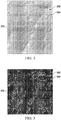
- the image 200 is an example of one implementation for the image 107 in Figure 1 .
- the image 200 may have been generated by, for example, a radar imaging system.
- the scene captured by the image 200 is of a portion of the terrain on the planet Mars.
- the image 200 may include a background 202 of Mars and terrain elements 204 located on Mars.
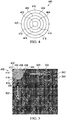
- the edge image 300 is an example of one implementation for the edge image 120 in Figure 1 .
- the edge image 300 is formed based on the image 200 in Figure 2 .
- the edge image 300 includes background pixels 302 and edge pixels 304.
- the edge pixels 304 represent the edges of the terrain elements 204 depicted in Figure 2 . These edges may be detected using any number of edge detection methods and/or techniques.
- generating the edge image 300 may include using an edge detection algorithm.
- the edge detection algorithm used may include at least one of, for example, without limitation, the Sobel edge detection filter, the Boie-Cox feature detector, the Canny edge detection method, or some other type of edge detection method.
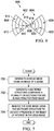
- the sectioned structure 400 in Figure 4 is an example of one implementation for the sectioned structure 142 in Figure 1 .
- the sectioned structure 400 may be used to analyze the edge image 300 in Figure 3 to determine whether an object of interest is present within the edge image 300 and to locate the object of interest in the edge image 300.
- the sectioned structure 400 is a series of concentric circles.
- the sectioned structure 400 may comprise circles 402, 404, 406, 408, and 410 that are concentric with respect to each other. These circles form sections 412, 414, 416, 418, and 420.
- Section 412 may be the center portion of the sectioned structure 400. Because the sectioned structure 400 is a series of concentric circles, processing of the edge image 300 may take into account all 360 degrees of possible orientations of the sensor system that generated the image 200 in Figure 2 relative to the scene captured in the image 200.
- the size of the circles 402, 404, 406, 408, and 410, and therefore the size of the sectioned structure 400, may be scaled based on the edge image 300 from Figure 3 and the range at which the image 200 from Figure 2 was generated. This range may be the altitude at which the image 200 in Figure 2 was generated.
- FIG. 5 an illustration of a sectioned structure being used to analyze an edge image is depicted in accordance with an illustrative embodiment.
- the sectioned structure 400 from Figure 4 is used to analyze the edge image 300 from Figure 3 .
- the sectioned structure 400 is used to determine whether an object of interest is present in the edge image 300 and to locate that object of interest if it is present.
- the sectioned structure 400 may be moved to various pixel locations over the edge image 300.
- the sectioned structure 400 may be moved over the edge image 300 in a manner similar to a raster pattern.
- the sectioned structure 400 may be moved over the edge image 300 in the direction of arrow 500 and in the direction of arrow 502.
- the number of pixels having a white value are divided by the number of pixels having a black value for each section in the sectioned structure 400 to form a density for each section.
- This density may be normalized to one in some cases to form a normalized density.
- the normalized densities for the different sections of the sectioned structure 400 may be compared against reference densities identified for a reference image containing an edge pattern that represents the object of interest to generate a variance for the pixel location. This process may be repeated for each pixel location in the edge image 300 over which the sectioned structure 400 is centered. All of the generated variances are compared.
- the pixel location having the minimum variance that is also below a selected threshold is identified as the location of the best-fit for the edge pattern and thereby, the location of the object of interest.
- the image processor may be configured to provide an output indicating that the object of interest has been detected.
- the output may take the form of, for example, without limitation, a visual alert, an audible alert, a message, a flashing graphical indicator, a print out, or some other type of output.
- This output may be used to communicate the detection of an object of interest for use in performing various operations including, but not limited to, activating an alarm, acquiring the location of a weapons target, tracking the weapons target, performing surveillance, and/or other types of operations.
- the sectioned structure 600 may be another example of an implementation for the sectioned structure 142 in Figure 1 .
- the sectioned structure 600 may have a plurality of sections that are split into a first portion 602 and a second portion 604.
- the first portion 602 and the second portion 604 may be a first sectioned wedge and a second sectioned wedge, respectively.
- the sectioned structure 600 may be a multi-wedge structure.
- the first portion 602 of the sectioned structure 600 includes sections 606, 608, 610, 612, and 614, which may be a first portion of the plurality of sections of the sectioned structure 600.
- the second portion 604 of the sectioned structure 600 includes sections 616, 618, 620, 622, and 624, which may be a second portion of the plurality of sections of the sectioned structure 600.
- the sections of the first portion 602 and the sections of the second portion 604 of the sectioned structure 600 may all be concentric in that they share the same center axis. In this manner, a sectioned structure that takes the form of a multi-wedge structure may still be a concentric structure.
- Using sectioned wedges, as compared to a series of concentric circles, may reduce processing time. In particular, using sectioned wedges may reduce the areas within which densities are to be calculated and thus, may speed up processing time.
- FIG. 7 an illustration of a process for detecting an object of interest in an image in the form of a flowchart is depicted in accordance with an illustrative embodiment.
- the process illustrated in Figure 7 may be implemented using the image processor 104 described in Figure 1 .
- the process begins by generating an edge image from an image of a scene (operation 700 ). Next, a sectioned structure comprising a plurality of sections is generated for use in analyzing the edge image (operation 702 ). Thereafter, the edge image is analyzed using the sectioned structure to detect a presence of an object of interest in the edge image (operation 704 ), with the process terminating thereafter.
- FIG. 8 an illustration of a process for detecting and locating an object of interest in an image in the form of a flowchart is depicted in accordance with an illustrative embodiment.
- the process illustrated in Figure 8 may be implemented using the image processor 104 described in Figure 1 .
- the process begins by receiving an image of a scene from a sensor system (operation 800 ). Next, an edge image is generated from the image received (operation 802 ). A sectioned structure comprising a plurality of sections is generated based on a selected range at which the image of the scene was generated (operation 804 ).
- a plurality of pixel locations in the edge image may be selected for processing (operation 806 ).
- a pixel location in the plurality of pixel locations is selected (operation 808 ).
- Each pixel location in the plurality of pixel locations selected may be a pixel location at which the sectioned structure will fully overlap the edge image when centered at the pixel location.
- the sectioned structure is moved over the edge image to the pixel location selected (operation 810 ).
- a plurality of densities are identified for the plurality of sections (operation 812 ).
- a density for a section of the sectioned structure is identified by dividing the number of edge pixels overlapped by the section by the total number of pixels overlapped by the section.
- the plurality of densities may be normalized densities that have normalized to, for example, one.
- the plurality of densities identified for the sectioned structure at the pixel location selected are compared to a plurality of reference densities for a reference image of an edge pattern that represents the object of interest to generate a variance for the pixel location (operation 814 ).
- a determination is then made as to whether any unprocessed pixel locations are present in the plurality of pixel locations selected (operation 816 ).
- the process returns to operation 808 as described above. Otherwise, the process determines whether the variance for any of the pixel locations is below a selected threshold (operation 818 ). If no variance for a pixel location is below the selected threshold, the process terminates because the object of interest has not been detected.
- the pixel location having the variance with the minimum value below the selected threshold is identified as the location of the best-fit for the edge pattern and thereby, the object of interest (operation 820 ).
- the object of interest is both detected and located in the edge image.
- the process described in Figure 8 may be used to detect and locate objects of interest in images quickly and efficiently.
- the object detection and location method described in Figure 8 may be applied to real-time applications. For example, images generated by an imaging system may be processed in substantially real-time such that an object of interest may be detected, located, and tracked in the images in substantially real-time.
- FIG. 9 an illustration of a process for generating a set of reference images for an object of interest is depicted in the form of a flowchart in accordance with an illustrative embodiment.
- the process illustrated in Figure 9 may be implemented using the image processor 104 in Figure 1 or some other computer, processor unit, or data processing system.
- the process begins by selecting an object of interest in a scene and a center of the object of interest (operation 900 ).
- an image of the object of interest is generated at each of a number of ranges using a sensor system (operation 902 ).
- an image of the object of interest may be generated with the sensor system located at different distances relative to the object of interest.
- an edge image is generated for each image of the object of interest generated for the number of ranges to form a set of reference images (operation 904 ).
- the edges in an edge image generated for a particular range may form an edge pattern that represents the object of interest at that range.
- a sectioned structure comprising a plurality of sections is generated for use in analyzing the set of reference images (operation 906 ).
- a reference image in the set of reference images is selected for processing (operation 908 ).
- the sectioned structure is scaled based on a range corresponding to the reference image selected (operation 910 ).
- the sectioned structure is then centered at a pixel location in the reference image corresponding to the center of the object of interest (operation 912 ).
- a plurality of densities are identified for the plurality of sections to form a plurality of reference densities for the reference image (operation 914 ).
- a determination is made as to whether any unprocessed reference images are present in the set of reference images (operation 916 ). If any unprocessed reference images are present in the set of reference images, the process returns to operation 908 as described above. Otherwise, the process terminates now that a plurality of reference densities have been identified for each of the set of reference images.
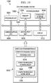
- FIG. 10 an illustration of a data processing system in the form of a block diagram is depicted.
- the data processing system 1000 performs one or more of the operations of the computer system 114.
- the data processing system 1000 includes a communications framework 1002, which provides communications between a processor unit 1004, storage devices 1006, a communications unit 1008, an input/output unit 1010, and a display 1012.
- the communications framework 1002 may be implemented as a bus system.
- the processor unit 1004 is configured to execute instructions for software to perform a number of operations.
- the processor unit 1004 may comprise a number of processors, a multi-processor core, and/or some other type of processor, depending on the implementation.
- the processor unit 1004 may take the form of a hardware unit, such as a circuit system, an application specific integrated circuit (ASIC), a programmable logic device, or some other suitable type of hardware unit.
- ASIC application specific integrated circuit
- the processor unit 1004 may be used to perform one or more of the operations performed by the image processor 104.
- the processor unit 1004 may be used to perform the operations of both the feature detector 116 and the feature analyzer 118 of the image processor 104.
- the processor unit 1004 may perform only the operations of the feature detector 116, while another processor unit in another computer may perform the operations of the feature analyzer 118. In this manner, the operations performed by the image processor 104 may be distributed over multiple processor units in multiple computers.
- Instructions for the operating system, applications, and/or programs run by the processor unit 1004 may be located in the storage devices 1006.
- the storage devices 1006 may be in communication with the processor unit 1004 through the communications framework 1002.
- a storage device which may also be referred to as a computer readable storage device, may include any piece of hardware capable of storing information on a temporary and/or permanent basis. This information may include, but is not limited to, data, program code, and/or other information.
- the memory 1014 and a persistent storage 1016 are examples of the storage devices 1006.
- the memory 1014 may take the form of, for example, a random access memory or some type of volatile or non-volatile storage device.
- the persistent storage 1016 may comprise any number of components or devices.
- the persistent storage 1016 may comprise a hard drive, a flash memory, a rewritable optical disk, a rewritable magnetic tape, or some combination of the above.
- the media used by the persistent storage 1016 may or may not be removable.
- the communications unit 1008 allows the data processing system 1000 to communicate with other data processing systems and/or devices.
- the communications unit 1008 may provide communications using physical and/or wireless communications links.
- the input/output unit 1010 allows input to be received from and output to be sent to other devices connected to the data processing system 1000.
- the input/output unit 1010 may allow user input to be received through a keyboard, a mouse, and/or some other type of input device.
- the input/output unit 1010 may allow output to be sent to a printer connected to the data processing system 1000.
- the input/output unit 1010 may be used to allow user input identifying the selected threshold 124 to be used by the feature detector 116. In some cases, the input/output unit 1010 may be used to output the location 156 of the object of interest 105, as identified by the feature analyzer 118, to a printer, the display 1012 of the data processing system 1000, or some other type of output device.
- the display 1012 is configured to display information to a user.
- the display 1012 may comprise, for example, without limitation, a monitor, a touch screen, a laser display, a holographic display, a virtual display device, and/or some other type of display device.
- the processes of the different illustrative embodiments may be performed by the processor unit 1004 using computer-implemented instructions. These instructions may be referred to as program code, computer usable program code, or computer readable program code and may be read and executed by one or more processors in the processor unit 1004.
- a program code 1018 is located in a functional form on a computer readable media 1020, which is selectively removable, and may be loaded onto or transferred to the data processing system 1000 for execution by the processor unit 1004.
- the program code 1018 may contain the instructions needed to perform at least one of the operations performed by the image processor 104.
- the program code 1018 and the computer readable media 1020 together form a computer program product 1022.
- the computer program product 1022 may be operable to be loaded on the data processing system 1000.
- the computer readable media 1020 may be a computer readable storage media 1024 or a computer readable signal media 1026.
- the computer readable storage media 1024 is a physical or tangible storage device used to store the program code 1018 rather than a medium that propagates or transmits the program code 1018.
- the computer readable storage media 1024 may include a non-transitory computer readable storage medium.
- the computer readable storage media 1024 may be, for example, without limitation, an optical or magnetic disk or a persistent storage device that is connected to the data processing system 1000.
- the program code 1018 may be transferred to the data processing system 1000 using the computer readable signal media 1026.
- the computer readable signal media 1026 may be, for example, a propagated data signal containing the program code 1018.
- This data signal may be an electromagnetic signal, an optical signal, and/or some other type of signal that can be transmitted over physical and/or wireless communications links.
- the illustration of the data processing system 1000 in Figure 10 is not meant to provide architectural limitations to the manner in which the illustrative embodiments may be implemented.
- the different illustrative embodiments may be implemented in a data processing system that includes components in addition to or in place of those illustrated for the data processing system 1000. Further, components shown in Figure 10 may be varied from the illustrative examples shown.
- each block in the flowcharts or block diagrams may represent a module, a segment, a function, and/or a portion of an operation or step.
- the function or functions noted in the blocks may occur out of the order noted in the figures.
- two blocks shown in succession may be executed substantially concurrently, or the blocks may sometimes be performed in the reverse order, depending upon the functionality involved.
- other blocks may be added in addition to the illustrated blocks in a flowchart or block diagram.
- the illustrative examples described in the figures above provide a method and apparatus for performing isotropic edge detection to identify and locate objects of interest.
- the illustrative examples are described with respect to identifying an object of interest, such as the object of interest 105 described in Figure 1 , in a single image, such as the image 107 described in Figure 1 , the isotropic edge detection may be used to identify an object of interest in each of a sequence of images.
- the isotropic edge detection may be used to identify an object of interest in each frame in a video such that the object of interest may be tracked through the video.
- the isotropic edge detection and edge analysis methods described by the different illustrative examples processing time and resources needed for this process may be reduced. As a result, this process may be useful for real-time applications that involve tracking an object of interest.
Landscapes
- Engineering & Computer Science (AREA)
- Computer Vision & Pattern Recognition (AREA)
- Theoretical Computer Science (AREA)
- Evolutionary Computation (AREA)
- Computing Systems (AREA)
- Databases & Information Systems (AREA)
- Artificial Intelligence (AREA)
- General Health & Medical Sciences (AREA)
- Medical Informatics (AREA)
- Software Systems (AREA)
- Health & Medical Sciences (AREA)
- Physics & Mathematics (AREA)
- General Physics & Mathematics (AREA)
- Multimedia (AREA)
- Image Analysis (AREA)
Description
- The present disclosure relates generally to identifying objects in images and, in particular, to identifying objects in images by detecting features representing the objects in the images. Still more particularly, the present disclosure relates to a method and apparatus for performing isotropic feature detection using sectioned structures to identify objects of interest in images.
- Object detection is the detection of objects of interest in images and/or video. An object of interest may be, for example, a building, a landscape element, a terrain element, an aerial vehicle, a ground vehicle, a missile, a spacecraft, or some other type of object. In this manner, an object of interest may be a natural or manmade object of interest.
- Object detection is a fundamental part of performing many different types of operations. For example, object detection may be used when performing surveillance operations, target tracking operations, target acquisition operations, target identification operations, and/or other types of operations.
- Object detection oftentimes includes performing feature detection. Feature detection is the detection of features of interest within an image. As used herein, a "feature," may be some type of discernible element or structure within an image. For example, a feature may be a point, an edge, or a shape in an image that represents an object or some portion of an object.
- In one illustrative example, an optical tracking system may be used to generate images of a target object. Feature detection may be used to identify the target object in the generated images based on the detection of features that represent the target object in the generated images. In this example, the ability to process images and detect features of interest quickly and efficiently may be crucial. Consequently, a method for feature detection that is not computationally intensive or time-consuming may be desired.
- Feature detection oftentimes includes edge detection. Edge detection is the detection of features in the form of edges. Oftentimes, with edge detection, an image, such as a camera image, is converted into a binary image in which pixels having one value represent a background and pixels having a another value represent edges. These binary images are also referred to as edge images. Pattern matching is then used to match the characteristics of the edges in an edge image with known patterns of edges for certain objects of interest.
- Using edge imagery may be beneficial because edge imagery may be relatively insensitive to changes in lighting. For example, the edges of an object may appear the same in an edge image whether the object of interest is brighter or darker than the background in the scene as long as the object of interest has distinctive edges.
- However, with some currently available methods of edge detection and pattern matching, analyzing images of a scene may take more time than desired for real-time applications. When using edge images, a pixel-by-pixel search may need to be made for locations in the image corresponding to a best-fit for an object of interest. The fit may be made by matching a template of an edge pattern that represents the object of interest to a portion of the edges in an edge image. This template may be referred to as an edge pattern template or in some cases, a wireframe template.
- Further, rotational adjustments may need to be made to take into account the different possible orientations of a scene relative to the imaging system generating the images of the scene. Still further, the range of a scene with respect to an imaging system may affect the positions, shapes, and/or sizes of edges that are detected. For example, the edges detected for images of terrain taken at higher elevations may be fewer than the edges detected for images taken at lower elevations.
- Creating an edge pattern template that accounts for different ranges may be more difficult than desired. Using a single edge pattern template for edge images corresponding to different ranges may reduce the overall accuracy with which objects of interest are detected and located. Therefore, it would be desirable to have a method and apparatus that take into account at least some of the issues discussed above, as well as other possible issues.
- "Shape Matching and Object Recognition Using Shape Contexts", Belongie et al., IEEE Transactions on Pattern Analysis and Machine Intelligence, Vol. 24, No. 24, April 2002, there is described shape matching and object recognition using shape contexts. The measurement of similarity is preceded by 1) solving for correspondences between points on the two shapes, 2) using the correspondences to estimate an aligning transform. A combination of region context structures and scale-invariant feature transform (SIFT) descriptors is disclosed in "Reinforcement Matching Using Region Context", Hongli Deng et al., Computer Vision and Pattern Recognition Workshop, 17 June 2006, while
CN 102 200 999 A also discloses employing shape contexts. - In "Histograms of oriented gradients for human detection", Dalal et al., Proceedings of the 2005 IEEE Computer Society Conference on Computer Vision and Pattern Recognition, there are described histograms of oriented gradients (HOG) for human detection. Local object appearance and shape can be characterised by the distribution of local intensity gradients or edge directions, even without precise knowledge of the corresponding gradient or edge positions. In practice this is implemented by dividing the image window into small spatial regions ("cells"), for each cell accumulating a local 1-D histogram of gradient directions or edge orientations over the pixels of the cell. The combined histogram entries form the representation. The disclosed "EC-HOG" descriptor employs in particular binary edge voting and a single orientation bin. In addition,
US 2012/070035 A1 discloses generating HOG descriptors based on high order statistics (HOS) information and employing them to perform template matching. - There is described herein a computer-implemented method for detecting an object of interest, the method comprising: generating an edge image from an image of a scene; generating a sectioned structure comprising a plurality of sections for use in analyzing the edge image; and analyzing the edge image using the sectioned structure to detect a presence of the object of interest in the edge image wherein analyzing the edge image using the sectioned structure to detect the presence of the object of interest in the edge image further comprises: identifying a plurality of variances for a plurality of pixel locations using the sectioned structure and a reference image; detecting the presence of the object of interest in the edge image in response to a determination that at least one pixel location in the plurality of pixel locations has a variance in the plurality of variances that is below a selected threshold; and identifying a location of the object of interest in the edge image as a pixel location having a minimum variance in the plurality of variances that is below the selected threshold, characterised in that identifying the plurality of variances for the plurality of pixel locations using the sectioned structure and the reference image comprises: identifying a plurality of densities for the plurality of sections of the sectioned structure at each of the plurality of pixel locations; and comparing the plurality of densities identified to a plurality of reference densities for the reference image to generate the plurality of variances for the plurality of pixel locations, wherein generating the sectioned structure comprises: identifying a selected range at which the image of the scene is generated, wherein the selected range is the distance between the scene and a sensor system at the time that the sensor system generated the image of the scene, said range being the altitude at which the image of the scene is generated; generating the sectioned structure comprising the plurality of sections; and scaling the sectioned structure based on the selected range; wherein analyzing the edge image using the sectioned structure to detect the presence of the object of interest in the edge image further comprises: selecting the reference image corresponding to a selected range at which the image is generated from a set of reference images in which the reference image contains an edge pattern representing the object of interest at the selected range, wherein selecting the reference image comprises selecting a first reference image from the set of reference images corresponding to a range just below the selected range and a second reference image from the set of reference images corresponding to a range just above the selected range, wherein the plurality of reference densities for the reference image are identified by an estimation technique using the first reference image selected, the second reference image selected, and at least one of a polynomial curve fitting technique, an interpolation technique, or some other type of technique to identify the reference densities.
- There is also described herein a system comprising: a feature detector configured to generate an edge image from an image of a scene; and a feature analyzer configured to generate a sectioned structure comprising a plurality of sections and to analyze the edge image using the sectioned structure to detect a presence of an object of interest in the edge image, characterised in that the feature analyzer is configured to: identify a plurality of variances for a plurality of pixel locations using the sectioned structure and a reference image; detect the presence of the object of interest in the edge image in response to a determination that at least one pixel location in the plurality of pixel locations has a variance in the plurality of variances that is below a selected threshold; and identify a location of the object of interest in the edge image as a pixel location having a minimum variance in the plurality of variances that is below the selected threshold, characterised in that identifying the plurality of variances for the plurality of pixel locations using the sectioned structure and the reference image comprises: identifying a plurality of densities for the plurality of sections of the sectioned structure at each of the plurality of pixel locations; and comparing the plurality of densities identified to a plurality of reference densities for the reference image to generate the plurality of variances for the plurality of pixel locations, wherein generating the sectioned structure comprises: identifying a selected range at which the image of the scene is generated, wherein the selected range is the distance between the scene and a sensor system at the time that the sensor system generated the image of the scene, said range being the altitude at which the image of the scene is generated; generating the sectioned structure comprising the plurality of sections; and scaling the sectioned structure based on the selected range; the system further comprising a library storing a set of reference images for a set of ranges, wherein the feature analyzer is further configured to select the reference image from the set of reference images and wherein the reference image contains an edge pattern representing the object of interest at the selected range, wherein the feature analyzer is configured to select the reference image, comprising selecting a first reference image from the set of reference images corresponding to a range just below the selected range and a second reference image from the set of reference images corresponding to a range just above the selected range, wherein the feature analyzer is further configured to use an estimation technique to identify the plurality of reference densities for the reference image using the first reference image selected, the second reference image selected, and at least one of a polynomial curve fitting technique, an interpolation technique, or some other type of technique to identify the reference densities.
- The features and functions can be achieved independently in various embodiments of the present disclosure in which further details can be seen with reference to the following description and drawings.
- The novel features believed characteristic of the illustrative embodiments are set forth in the appended claims. The illustrative embodiments, however, as well as a preferred mode of use, further objectives and features thereof, will best be understood by reference to the following detailed description of an illustrative embodiment of the present disclosure when read in conjunction with the accompanying drawings, wherein:
-
Figure 1 is an illustration of an image processing environment in the form of a block diagram in accordance with an illustrative embodiment; -
Figure 2 is an illustration of an image in accordance with an illustrative embodiment; -
Figure 3 is an illustration of an edge image in accordance with an illustrative embodiment; -
Figure 4 is an illustration of a sectioned structure in accordance with an illustrative embodiment; -
Figure 5 is an illustration of a sectioned structure being used to analyze an edge image in accordance with an illustrative embodiment; -
Figure 6 is an illustration of another sectioned structure in accordance with an illustrative embodiment; -
Figure 7 is an illustration of a process for detecting an object of interest in an image in the form of a flowchart in accordance with an illustrative embodiment; -
Figure 8 is an illustration of a process for detecting and locating an object of interest in an image in the form of a flowchart in accordance with an illustrative embodiment; -
Figure 9 is an illustration of a process for generating a set of reference images for an object of interest in the form of a flowchart in accordance with an illustrative embodiment; and -
Figure 10 is an illustration of a data processing environment in the form of a block diagram in accordance with an illustrative embodiment. - The illustrative embodiments recognize and take into account different considerations. For example, the illustrative embodiments recognize and take into account that using edge imagery to detect and locate features of interest in images may become increasingly limited as the number of pixels in the images increases. For example, an edge pattern template may be 100 pixels by 100 pixels. However, the edge image to be analyzed using the edge pattern template may be 640 pixels by 480 pixels. When no rotational adjustments are made, about 2 billion pixel-by-pixel comparisons may need to be processed. When rotational adjustments do need to be made, the number of comparisons needed may increase to over 730 billion comparisons for one degree of accuracy.
- Consequently, the different illustrative examples recognize and take into account that it may be desirable to have a method and apparatus for detecting objects of interest that do not need to perform additional rotational adjustments. In other words, it may be desirable to have a method and apparatus for isotropically detecting objects of interest.
- Referring now to the figures and, in particular, with reference to
Figure 1 , an illustration of an image processing environment is depicted in the form of a block diagram in accordance with an illustrative embodiment. In this illustrative example, theimage processing environment 100 may include asensor system 102 and animage processor 104. - The
sensor system 102 may be used to generateimaging data 106 for ascene 108. Depending on the implementation, theimaging data 106 may include, for example, without limitation, animage 107 of thescene 108, an electronic data file associated with animage 107 of thescene 108, data that may be used to form animage 107 of thescene 108, and/or other types of data. - In this illustrative example, the
imaging data 106 may include animage 107 of thescene 108. Although only oneimage 107 is described as being generated, thesensor system 102 may be used to generate any number of images. For example, thesensor system 102 may be used to generate a sequence of images in the form of a video. A sequence of images may include two or more images ordered with respect to time. - The
scene 108 captured in theimage 107 may include a set ofobjects 110. As used herein, a "set of" items may include one or more items. In this manner, the set ofobjects 110 may include one or more objects. As used herein, an "object" may be any type of natural or manmade object. For example, an object in the set ofobjects 110 may take the form of a building, an aircraft, a ground vehicle, a terrain feature, a landscape feature, a mountain ridge, a group of mountain ridges, a crater, or some other type of object or combination thereof. - In one illustrative example, the
sensor system 102 takes the form of animaging system 112. Theimaging system 112 may be implemented using, for example, without limitation, a camera, an electro-optical imaging system, a radar imaging system, an infrared imaging system, a laser imaging system, or some other type of imaging system configured for generatingimaging data 106. - In this illustrative example, the
image processor 104 is configured to receive and process theimaging data 106 generated by thesensor system 102. In particular, theimage processor 104 is used to detect the presence of an object ofinterest 105 in the set ofobjects 110 in thescene 108 based on theimaging data 106 generated for thescene 108. - The
image processor 104 may be implemented using hardware, software, firmware, or a combination thereof. When software is used, the operations performed by theimage processor 104 may be implemented using program code configured to run on a processor unit. The program code may be stored in a non-transitory computer readable storage medium. When firmware is used, the operations performed by theimage processor 104 may be implemented using, for example, without limitation, program code and data stored in persistent memory configured to run on a processor unit. - When hardware is employed, the hardware may include one or more circuits that operate to perform the operations performed by the
image processor 104. Depending on the implementation, the hardware may take the form of a circuit system, a microchip, an integrated circuit, an application specific integrated circuit (ASIC), a programmable logic device, or some other suitable type of hardware device configured to perform any number of operations. In some cases, the operations performed by theimage processor 104 may be implemented using a processor unit. Depending on the implementations, the operations performed by theimage processor 104 may be performed by a group of processor units. - In one illustrative example, the
image processor 104 may be implemented using acomputer system 114 comprised of one or more computers. When more than one computer is present in thecomputer system 114, these computers may be in communication with each other. When more than one computer is present in thecomputer system 114, the different operations performed by theimage processor 104 may be distributed across these computers. - When the
imaging data 106 includes an electronic data file associated with theimage 107 of thescene 108 or other data that may be used to generate theimage 107 of thescene 108, theimage processor 104 may process theimaging data 106 to form theimage 107 of thescene 108. Theimage 107 of thescene 108 may then be used to detect the presence of the object ofinterest 105 in thescene 108. - As depicted, the
image processor 104 may include afeature detector 116 and afeature analyzer 118. In one illustrative example, theimage processor 104 may take the form of, for example, without limitation, a processor or microprocessor having encoded instructions therein that are executable to function as afeature detector 116, and further instructions that are executable to function as afeature analyzer 118. - The
feature detector 116 is used to detect features within theimage 107. Thefeature analyzer 118 is used to analyze the features detected within theimage 107. Thefeature detector 116 may be used to detect features such as, for example, without limitation, points, edges, and/or objects in theimage 107. - In this illustrative example, the
feature detector 116 may be used to detect edges within theimage 107. In this manner, thefeature detector 116 may be referred to as an edge detector that performs edge detection. Edge detection may be the detection of features in the form of edges in an image. In edge detection, an image, such as theimage 107 of thescene 108, is converted into an edge image. An edge image may be a binary image in which pixels having one value represent a background and pixels having another contrasting or differing value represent edges. - Using edge imagery may be beneficial because edge imagery may be relatively insensitive to changes in lighting. For example, the edges of an object may appear the same in an edge image whether the object is brighter or darker than the background in the scene as long as the object in the edge image has distinctive edges.
- In this illustrative example, the
feature detector 116 may process theimage 107 to form anedge image 120 havingedges 121. Theedge image 120 may be formed in a number of different ways using any number of edge detection algorithms and/or image processing techniques. - In one illustrative example, the
feature detector 116 first forms agrayscale image 122 from theimage 107. Next, each pixel in thegrayscale image 122 is compared against a selectedthreshold 124 for determining which pixels contrast in brightness relative to other adjacent pixels, e.g., where brightness changes sharply, to form theedge image 120. In particular, each pixel in thegrayscale image 122 having a pixel value equal to or greater than a selectedthreshold 124 may be set to a first pixel value. The first pixel value may be, for example, a white value. Further, each pixel in thegrayscale image 122 having a pixel value lower than the selectedthreshold 124 may be set to a second pixel value. The second pixel value may be, for example, a black value. In this manner, thegrayscale image 122 may be thresholded to form abinary image 126 in which each pixel in thebinary image 126 has only one of two possible pixel values. - Depending on the implementation, the
binary image 126 may be further processed using one or more edge detection techniques and/or filters to form theedge image 120. In other illustrative examples, thegrayscale image 122 may be processed using an edge detection algorithm prior to being thresholded. In these examples, thebinary image 126 formed may be theedge image 120. - The
edge image 120 may include a plurality ofpixels 128. A first portion of thepixels 128 in theedge image 120 may bebackground pixels 130. A second portion of thepixels 128 in theedge image 120 may beedge pixels 132. Each of thebackground pixels 130 may have a first pixel value and each of theedge pixels 132 may have a second pixel value that is different from the first pixel value. Theedge pixels 132 form theedges 121 in theedge image 120. - In this illustrative example, the
edge image 120 is then sent to thefeature analyzer 118 for processing. Thefeature analyzer 118 identifies the selectedrange 140 corresponding to theimage 107. The selectedrange 140 is the distance between thescene 108 and thesensor system 102 at the time that thesensor system 102 generated theimaging data 106 for thescene 108. - The
feature analyzer 118 may then use pattern matching to match the characteristics of theedges 121 in theedge image 120 with a known pattern of edges for the objects ofinterest 105. A pixel-by-pixel search is made for locations in theedge image 120 corresponding to a best-fit for the object ofinterest 105. The fit is preferably made by matching a known edge pattern that represents the object ofinterest 105 to a portion of theedges 121 in theedge image 120. In some cases, this known edge pattern may be referred to as an edge pattern template or a wireframe template. - Creating an edge pattern template that accounts for different ranges may be more difficult than desired. Using a single edge pattern template for edge images corresponding to different ranges relative to the ground may reduce the overall accuracy with which objects of interest are detected and located in the edge image. Consequently, the
feature analyzer 118 may need to match the characteristics of theedges 121 in theedge image 120 with anedge pattern 138 for the object ofinterest 105 that corresponds to the selectedrange 140. Theedge pattern 138 corresponding to the selectedrange 140 may be a pattern of edges that represent the object ofinterest 105 at the selectedrange 140 corresponding to theimage 107 from which theedge image 120 was created. Matching theedge pattern 138 to the characteristics of theedges 121 in theedge image 120 may be referred to as detecting the presence of theedge pattern 138 in theedge image 120. - In this illustrative example, the
feature analyzer 118 may use a set ofreference images 134 stored in alibrary 135 to detect the presence of theedge pattern 138 corresponding to the selectedrange 140 in theedge image 120. Thelibrary 135 may be implemented using, for example, without limitation, a database, a data structure, or some other type of data storage configured to store the set ofreference images 134. Each reference image in the set ofreference images 134 may contain an edge pattern representing the object ofinterest 105 at a particular range. In this illustrative example, aparticular reference image 136 may contain theedge pattern 138 that represents the object ofinterest 105 at the selectedrange 140. - In particular, the
reference image 136 may be an edge image generated from an image of the object ofinterest 105 taken by a sensor system at the selectedrange 140 relative to the object ofinterest 105. This sensor system may or may not be the same as thesensor system 102 used to generate theoriginal image 107, but may be of the same type. Each of the set ofreference images 134 may be a reference edge image corresponding to a particular range. - The
feature analyzer 118 then generates a sectionedstructure 142 for use in analyzing theedge image 120. The sectionedstructure 142 may be scaled in size based on the selectedrange 140. As depicted, the sectionedstructure 142 may be comprised of a plurality ofsections 144. In one illustrative example, the sectionedstructure 142 is a series of concentric circles, or rings. Thesections 144 may include the bands and the center area formed by this series of concentric rings. In this manner, the sectionedstructure 142 may be a concentric structure in which the plurality ofsections 144 are concentric sections that share a same center axis. - The
feature analyzer 118 may position the sectionedstructure 142 over theedge image 120 to analyze theedge image 120. In particular, thefeature analyzer 118 may center the sectionedstructure 142 over each of a plurality ofpixel locations 146 in theedge image 120. Thesepixel locations 146 may include at least a portion of the possible pixel locations in theedge image 120. Each of thepixel locations 146 may be selected such that the sectionedstructure 142 fully overlaps theedge image 120. In other words, thepixel locations 146 may be selected such that the sectionedstructure 142 is fully contained within the boundaries of theedge image 120 at each of thepixel locations 146. - At each
pixel location 148, thefeature analyzer 118 identifies a plurality ofdensities 150. In particular, at eachpixel location 148, thefeature analyzer 118 counts the number of theedge pixels 132 within each of thesections 144 and divides this number by the total number of pixels within that section to generate a density. - In some cases, the
densities 150 identified for thesections 144 may be normalized to form a plurality of normalized densities. For example, thedensities 150 identified for thesections 144 at aparticular pixel location 148 may be normalized to one. - The sectioned
structure 142 is generated such that the orientation of thesensor system 102 relative to thescene 108 within some selected range of possible orientations does not need to be taken into account. In other words, thedensities 150 identified at aparticular pixel location 148 may represent a density of edges for thatpixel location 148 that is independent of the angle of rotation of thesensor system 102 relative to thescene 108. In this manner, the calculation of thedensities 150 for thepixel location 148 may be performed isotropically. - The
densities 150 identified are then compared to a plurality ofreference densities 152 for thereference image 136 containing theedge pattern 138 corresponding to the selectedrange 140. Thereference densities 152 may have been identified by analyzing thereference image 136 using a sectioned structure, similar to the sectionedstructure 142 used by thefeature analyzer 118 for analyzing theedge image 120. - The
feature analyzer 118 compares thedensities 150 to thereference densities 152 to identify anoverall variance 154 for thepixel location 148. Theoverall variance 154 may be an indicator of how closely thedensities 150 match thereference densities 152. The lower the variance, the more closely that thedensities 150 match thereference densities 152. - The process described above may be repeated for each of the
pixel locations 146 in order to generate a plurality of variances for thepixel locations 146. Thefeature analyzer 118 may identify the pixel location in theedge image 120 having the minimum variance that is also below a selected threshold as thelocation 156 of theedge pattern 138 in theedge image 120. If no pixel locations have a variance that is below the selected threshold, then theedge pattern 138 is considered not detected, or present, within theedge image 120. - In this manner, the
edge pattern 138 may be detected and located using the sectionedstructure 142. The sectionedstructure 142 may be used without requiring any further adjustments to take into account different possible orientations of thesensor system 102 relative to thescene 108. In other words, the sectionedstructure 142 may be used to perform isotropic edge detection. - The
location 156 of theedge pattern 138 is the location at which theedges 121 in theedge image 120 best-fit theedge pattern 138 representing the object ofinterest 105. Thelocation 156 identified is also the same pixel location for the object ofinterest 105 in theimage 107 of thescene 108 identified from theimaging data 106 generated by thesensor system 102. When theedge pattern 138 is not detected in theedge image 120, the object ofinterest 105 is considered not detected. - In this manner, a determination as to whether the object of
interest 105 is represented by a portion of theedges 121 in theedge image 120 may be made by analyzing theedge image 120 using thereference image 136 corresponding to the selectedrange 140 and the sectionedstructure 142. Detecting a representation of the object ofinterest 105 within theedge image 120 based on identifying theedge pattern 138 contained in thereference image 136 as being present within theedge image 120 may be equivalent to a detection of the object ofinterest 105 in theimage 107 of thescene 108. - This type of processing may be used to detect and track objects of interest in images quickly and efficiently for real-time and/or near real-time applications. The
image processor 104 allows features to be detected and analyzed in images without having to make rotational adjustments to account for variations in the orientation of a sensor system relative to a scene. In this manner, the amount of time needed to process a single image may be significantly reduced. - In particular, using the sectioned
structure 142 may reduce the amount of processing resources used by theimage processor 104 when detecting the object ofinterest 105. These processing resources may include, for example, without limitation, the time, processing power, memory, and/or other types of resources needed to process images to detect the presence of objects of interest within these images. - The illustration of the
image processing environment 100 inFigure 1 is not meant to imply physical or architectural limitations to the manner in which an illustrative embodiment may be implemented. Other components in addition to or in place of the ones illustrated may be used. Some components may be optional. Also, the blocks are presented to illustrate some functional components. One or more of these blocks may be combined, divided, or combined and divided into different blocks when implemented in an illustrative embodiment. - In some illustrative examples, the set of
reference images 134 may not include areference image 136 containing theedge pattern 138 corresponding to the selectedrange 140. In these cases, thefeature analyzer 118 may be configured to select a first reference image from the set ofreference images 134 corresponding to a range just below the selectedrange 140 and a second reference image from the set ofreference images 134 corresponding to a range just above the selectedrange 140. - The
feature analyzer 118 may use an estimation technique to identify thereference densities 152 with which thedensities 150 will be compared. For example, without limitation, thefeature analyzer 118 may use the first reference image selected, the second reference image selected, and at least one of a polynomial curve fitting technique, an interpolation technique, or some other type of technique to identify thereference densities 152. - In this manner, the
feature analyzer 118 may be able to evaluate edge images for various ranges, including those for which reference images are not included in the set ofreference images 134. In other words, thefeature analyzer 118 may be able to evaluate edge images over a continuum of ranges and not just a discrete set of ranges. - Further, although the
feature detector 116 has been described as generating edge images to detect edges, thefeature detector 116 may be configured to detect other types of features. Further, thefeature analyzer 118 may be configured to analyze these other types of features. - With reference now to
Figure 2 , an illustration of an image is depicted in accordance with an illustrative embodiment. In this illustrative example, theimage 200 is an example of one implementation for theimage 107 inFigure 1 . Theimage 200 may have been generated by, for example, a radar imaging system. - In this illustrative example, the scene captured by the
image 200 is of a portion of the terrain on the planet Mars. As depicted, theimage 200 may include abackground 202 of Mars andterrain elements 204 located on Mars. - Turning now to
Figure 3 , an illustration of an edge image is depicted in accordance with an illustrative embodiment. In this illustrative example, theedge image 300 is an example of one implementation for theedge image 120 inFigure 1 . Theedge image 300 is formed based on theimage 200 inFigure 2 . - As depicted, the
edge image 300 includesbackground pixels 302 and edgepixels 304. Theedge pixels 304 represent the edges of theterrain elements 204 depicted inFigure 2 . These edges may be detected using any number of edge detection methods and/or techniques. - For example, generating the
edge image 300 may include using an edge detection algorithm. The edge detection algorithm used may include at least one of, for example, without limitation, the Sobel edge detection filter, the Boie-Cox feature detector, the Canny edge detection method, or some other type of edge detection method. - With reference now to
Figure 4 , an illustration of a sectioned structure is depicted in accordance with an illustrative embodiment. The sectionedstructure 400 inFigure 4 is an example of one implementation for the sectionedstructure 142 inFigure 1 . The sectionedstructure 400 may be used to analyze theedge image 300 inFigure 3 to determine whether an object of interest is present within theedge image 300 and to locate the object of interest in theedge image 300. - As depicted, the sectioned
structure 400 is a series of concentric circles. In particular, the sectionedstructure 400 may comprisecircles sections Section 412 may be the center portion of the sectionedstructure 400. Because the sectionedstructure 400 is a series of concentric circles, processing of theedge image 300 may take into account all 360 degrees of possible orientations of the sensor system that generated theimage 200 inFigure 2 relative to the scene captured in theimage 200. - The size of the
circles structure 400, may be scaled based on theedge image 300 fromFigure 3 and the range at which theimage 200 fromFigure 2 was generated. This range may be the altitude at which theimage 200 inFigure 2 was generated. - With reference now to
Figure 5 , an illustration of a sectioned structure being used to analyze an edge image is depicted in accordance with an illustrative embodiment. In this illustrative example, the sectionedstructure 400 fromFigure 4 is used to analyze theedge image 300 fromFigure 3 . In particular, the sectionedstructure 400 is used to determine whether an object of interest is present in theedge image 300 and to locate that object of interest if it is present. - As depicted, the sectioned
structure 400 may be moved to various pixel locations over theedge image 300. In one illustrative example, the sectionedstructure 400 may be moved over theedge image 300 in a manner similar to a raster pattern. For example, the sectionedstructure 400 may be moved over theedge image 300 in the direction ofarrow 500 and in the direction ofarrow 502. - At each pixel location in the
edge image 300 over which the sectionedstructure 400 is centered, the number of pixels having a white value are divided by the number of pixels having a black value for each section in the sectionedstructure 400 to form a density for each section. This density may be normalized to one in some cases to form a normalized density. The normalized densities for the different sections of the sectionedstructure 400 may be compared against reference densities identified for a reference image containing an edge pattern that represents the object of interest to generate a variance for the pixel location. This process may be repeated for each pixel location in theedge image 300 over which the sectionedstructure 400 is centered. All of the generated variances are compared. The pixel location having the minimum variance that is also below a selected threshold is identified as the location of the best-fit for the edge pattern and thereby, the location of the object of interest. - In some illustrative examples, once the location of the best-fit for the edge pattern and thereby, the object of interest, has been identified, the image processor may be configured to provide an output indicating that the object of interest has been detected. The output may take the form of, for example, without limitation, a visual alert, an audible alert, a message, a flashing graphical indicator, a print out, or some other type of output. This output may be used to communicate the detection of an object of interest for use in performing various operations including, but not limited to, activating an alarm, acquiring the location of a weapons target, tracking the weapons target, performing surveillance, and/or other types of operations.
- With reference now to
Figure 6 , an illustration of another sectioned structure is depicted in accordance with an illustrative embodiment. The sectionedstructure 600 may be another example of an implementation for the sectionedstructure 142 inFigure 1 . The sectionedstructure 600 may have a plurality of sections that are split into afirst portion 602 and asecond portion 604. As depicted, thefirst portion 602 and thesecond portion 604 may be a first sectioned wedge and a second sectioned wedge, respectively. In this manner, the sectionedstructure 600 may be a multi-wedge structure. - As depicted, the
first portion 602 of the sectionedstructure 600 includessections structure 600. Thesecond portion 604 of the sectionedstructure 600 includessections structure 600. - The sections of the
first portion 602 and the sections of thesecond portion 604 of the sectionedstructure 600 may all be concentric in that they share the same center axis. In this manner, a sectioned structure that takes the form of a multi-wedge structure may still be a concentric structure. Using sectioned wedges, as compared to a series of concentric circles, may reduce processing time. In particular, using sectioned wedges may reduce the areas within which densities are to be calculated and thus, may speed up processing time. - With reference now to
Figure 7 , an illustration of a process for detecting an object of interest in an image in the form of a flowchart is depicted in accordance with an illustrative embodiment. The process illustrated inFigure 7 may be implemented using theimage processor 104 described inFigure 1 . - The process begins by generating an edge image from an image of a scene (operation 700). Next, a sectioned structure comprising a plurality of sections is generated for use in analyzing the edge image (operation 702). Thereafter, the edge image is analyzed using the sectioned structure to detect a presence of an object of interest in the edge image (operation 704), with the process terminating thereafter.
- With reference now to
Figure 8 , an illustration of a process for detecting and locating an object of interest in an image in the form of a flowchart is depicted in accordance with an illustrative embodiment. The process illustrated inFigure 8 may be implemented using theimage processor 104 described inFigure 1 . - The process begins by receiving an image of a scene from a sensor system (operation 800). Next, an edge image is generated from the image received (operation 802). A sectioned structure comprising a plurality of sections is generated based on a selected range at which the image of the scene was generated (operation 804).
- Thereafter, a plurality of pixel locations in the edge image may be selected for processing (operation 806). A pixel location in the plurality of pixel locations is selected (operation 808). Each pixel location in the plurality of pixel locations selected may be a pixel location at which the sectioned structure will fully overlap the edge image when centered at the pixel location.
- Next, the sectioned structure is moved over the edge image to the pixel location selected (operation 810). A plurality of densities are identified for the plurality of sections (operation 812). In
operation 812, a density for a section of the sectioned structure is identified by dividing the number of edge pixels overlapped by the section by the total number of pixels overlapped by the section. In some cases, the plurality of densities may be normalized densities that have normalized to, for example, one. - Thereafter, the plurality of densities identified for the sectioned structure at the pixel location selected are compared to a plurality of reference densities for a reference image of an edge pattern that represents the object of interest to generate a variance for the pixel location (operation 814). A determination is then made as to whether any unprocessed pixel locations are present in the plurality of pixel locations selected (operation 816).
- If any unprocessed pixel locations are present, the process returns to
operation 808 as described above. Otherwise, the process determines whether the variance for any of the pixel locations is below a selected threshold (operation 818). If no variance for a pixel location is below the selected threshold, the process terminates because the object of interest has not been detected. - Otherwise, if the variance for any of the pixel locations is below the selected threshold, the pixel location having the variance with the minimum value below the selected threshold is identified as the location of the best-fit for the edge pattern and thereby, the object of interest (operation 820). In other words, in
operation 820, the object of interest is both detected and located in the edge image. - The process described in
Figure 8 may be used to detect and locate objects of interest in images quickly and efficiently. The object detection and location method described inFigure 8 may be applied to real-time applications. For example, images generated by an imaging system may be processed in substantially real-time such that an object of interest may be detected, located, and tracked in the images in substantially real-time. - With reference now to
Figure 9 , an illustration of a process for generating a set of reference images for an object of interest is depicted in the form of a flowchart in accordance with an illustrative embodiment. The process illustrated inFigure 9 may be implemented using theimage processor 104 inFigure 1 or some other computer, processor unit, or data processing system. - The process begins by selecting an object of interest in a scene and a center of the object of interest (operation 900). Next, an image of the object of interest is generated at each of a number of ranges using a sensor system (operation 902). In other words, in
operation 902, an image of the object of interest may be generated with the sensor system located at different distances relative to the object of interest. - Then, an edge image is generated for each image of the object of interest generated for the number of ranges to form a set of reference images (operation 904). The edges in an edge image generated for a particular range may form an edge pattern that represents the object of interest at that range.
- Thereafter, a sectioned structure comprising a plurality of sections is generated for use in analyzing the set of reference images (operation 906). A reference image in the set of reference images is selected for processing (operation 908). The sectioned structure is scaled based on a range corresponding to the reference image selected (operation 910).
- The sectioned structure is then centered at a pixel location in the reference image corresponding to the center of the object of interest (operation 912). A plurality of densities are identified for the plurality of sections to form a plurality of reference densities for the reference image (operation 914). Next, a determination is made as to whether any unprocessed reference images are present in the set of reference images (operation 916). If any unprocessed reference images are present in the set of reference images, the process returns to
operation 908 as described above. Otherwise, the process terminates now that a plurality of reference densities have been identified for each of the set of reference images. - Turning now to
Figure 10 , an illustration of a data processing system in the form of a block diagram is depicted. In one illustrative embodiment, thedata processing system 1000 performs one or more of the operations of thecomputer system 114. - As depicted, the
data processing system 1000 includes acommunications framework 1002, which provides communications between aprocessor unit 1004,storage devices 1006, acommunications unit 1008, an input/output unit 1010, and adisplay 1012. In some cases, thecommunications framework 1002 may be implemented as a bus system. - The
processor unit 1004 is configured to execute instructions for software to perform a number of operations. Theprocessor unit 1004 may comprise a number of processors, a multi-processor core, and/or some other type of processor, depending on the implementation. In some cases, theprocessor unit 1004 may take the form of a hardware unit, such as a circuit system, an application specific integrated circuit (ASIC), a programmable logic device, or some other suitable type of hardware unit. - In one illustrative example, the
processor unit 1004 may be used to perform one or more of the operations performed by theimage processor 104. For example, theprocessor unit 1004 may be used to perform the operations of both thefeature detector 116 and thefeature analyzer 118 of theimage processor 104. In other examples, theprocessor unit 1004 may perform only the operations of thefeature detector 116, while another processor unit in another computer may perform the operations of thefeature analyzer 118. In this manner, the operations performed by theimage processor 104 may be distributed over multiple processor units in multiple computers. - Instructions for the operating system, applications, and/or programs run by the
processor unit 1004 may be located in thestorage devices 1006. Thestorage devices 1006 may be in communication with theprocessor unit 1004 through thecommunications framework 1002. A storage device, which may also be referred to as a computer readable storage device, may include any piece of hardware capable of storing information on a temporary and/or permanent basis. This information may include, but is not limited to, data, program code, and/or other information. - The
memory 1014 and apersistent storage 1016 are examples of thestorage devices 1006. Thememory 1014 may take the form of, for example, a random access memory or some type of volatile or non-volatile storage device. Thepersistent storage 1016 may comprise any number of components or devices. For example, thepersistent storage 1016 may comprise a hard drive, a flash memory, a rewritable optical disk, a rewritable magnetic tape, or some combination of the above. The media used by thepersistent storage 1016 may or may not be removable. - The
communications unit 1008 allows thedata processing system 1000 to communicate with other data processing systems and/or devices. Thecommunications unit 1008 may provide communications using physical and/or wireless communications links. - The input/
output unit 1010 allows input to be received from and output to be sent to other devices connected to thedata processing system 1000. For example, the input/output unit 1010 may allow user input to be received through a keyboard, a mouse, and/or some other type of input device. As another example, the input/output unit 1010 may allow output to be sent to a printer connected to thedata processing system 1000. - In one illustrative example, the input/
output unit 1010 may be used to allow user input identifying the selectedthreshold 124 to be used by thefeature detector 116. In some cases, the input/output unit 1010 may be used to output thelocation 156 of the object ofinterest 105, as identified by thefeature analyzer 118, to a printer, thedisplay 1012 of thedata processing system 1000, or some other type of output device. - The
display 1012 is configured to display information to a user. Thedisplay 1012 may comprise, for example, without limitation, a monitor, a touch screen, a laser display, a holographic display, a virtual display device, and/or some other type of display device. - In this illustrative example, the processes of the different illustrative embodiments may be performed by the
processor unit 1004 using computer-implemented instructions. These instructions may be referred to as program code, computer usable program code, or computer readable program code and may be read and executed by one or more processors in theprocessor unit 1004. - In these examples, a
program code 1018 is located in a functional form on a computerreadable media 1020, which is selectively removable, and may be loaded onto or transferred to thedata processing system 1000 for execution by theprocessor unit 1004. In one illustrative example, theprogram code 1018 may contain the instructions needed to perform at least one of the operations performed by theimage processor 104. - The
program code 1018 and the computerreadable media 1020 together form acomputer program product 1022. Thecomputer program product 1022 may be operable to be loaded on thedata processing system 1000. - In this illustrative example, the computer
readable media 1020 may be a computerreadable storage media 1024 or a computerreadable signal media 1026. The computerreadable storage media 1024 is a physical or tangible storage device used to store theprogram code 1018 rather than a medium that propagates or transmits theprogram code 1018. In one illustrative example, the computerreadable storage media 1024 may include a non-transitory computer readable storage medium. The computerreadable storage media 1024 may be, for example, without limitation, an optical or magnetic disk or a persistent storage device that is connected to thedata processing system 1000. - Alternatively, the
program code 1018 may be transferred to thedata processing system 1000 using the computerreadable signal media 1026. The computerreadable signal media 1026 may be, for example, a propagated data signal containing theprogram code 1018. This data signal may be an electromagnetic signal, an optical signal, and/or some other type of signal that can be transmitted over physical and/or wireless communications links. - The illustration of the
data processing system 1000 inFigure 10 is not meant to provide architectural limitations to the manner in which the illustrative embodiments may be implemented. The different illustrative embodiments may be implemented in a data processing system that includes components in addition to or in place of those illustrated for thedata processing system 1000. Further, components shown inFigure 10 may be varied from the illustrative examples shown. - The flowcharts and block diagrams in the different depicted embodiments illustrate the architecture, functionality, and operation of some possible implementations of apparatuses and methods in an illustrative embodiment. In this regard, each block in the flowcharts or block diagrams may represent a module, a segment, a function, and/or a portion of an operation or step.
- In some alternative implementations of an illustrative embodiment, the function or functions noted in the blocks may occur out of the order noted in the figures. For example, in some cases, two blocks shown in succession may be executed substantially concurrently, or the blocks may sometimes be performed in the reverse order, depending upon the functionality involved. Also, other blocks may be added in addition to the illustrated blocks in a flowchart or block diagram.
- Thus, the illustrative examples described in the figures above provide a method and apparatus for performing isotropic edge detection to identify and locate objects of interest. Although the illustrative examples are described with respect to identifying an object of interest, such as the object of
interest 105 described inFigure 1 , in a single image, such as theimage 107 described inFigure 1 , the isotropic edge detection may be used to identify an object of interest in each of a sequence of images. - For example, the isotropic edge detection may be used to identify an object of interest in each frame in a video such that the object of interest may be tracked through the video. By using the isotropic edge detection and edge analysis methods described by the different illustrative examples, processing time and resources needed for this process may be reduced. As a result, this process may be useful for real-time applications that involve tracking an object of interest.
Claims (7)
- A computer-implemented method for detecting an object of interest (105), the method comprising:generating an edge image (120) from an image of a scene (108);generating a sectioned structure (142) comprising a plurality of sections (144) for use in analyzing the edge image (120); andanalyzing the edge image (120) using the sectioned structure (142) to detect a presence of the object of interest (105) in the edge image (120),wherein analyzing the edge image (120) using the sectioned structure (142) to detect the presence of the object of interest (105) in the edge image (120) further comprises:identifying a plurality of variances for a plurality of pixel locations (146) using the sectioned structure (142) and a reference image (136);detecting the presence of the object of interest (105) in the edge image (120) in response to a determination that at least one pixel location (148) in the plurality of pixel locations (146) has a variance (154) in the plurality of variances that is below a selected threshold (124); andidentifying a location (156) of the object of interest (105) in the edge image (120) as a pixel location (148) having a minimum variance (154) in the plurality of variances that is below the selected threshold (124), characterised in that identifying the plurality of variances for the plurality of pixel locations (146) using the sectioned structure (142) and the reference image (136) comprises:identifying a plurality of densities (150) for the plurality of sections (144) of the sectioned structure (142) at each of the plurality of pixel locations (146); andcomparing the plurality of densities (150) identified to a plurality of reference densities (152) for the reference image (136) to generate the plurality of variances for the plurality of pixel locations (146),wherein generating the sectioned structure (142) comprises:identifying a selected range (140) at which the image (107) of the scene (108) is generated, wherein the selected range (140) is the distance between the scene (108) and a sensor system (102) at the time that the sensor system (102) generated the image (107) of the scene (108), said range being the altitude at which the image (107) of the scene (108) is generated;generating the sectioned structure (142) comprising the plurality of sections (144); andscaling the sectioned structure (142) based on the selected range (140);wherein analyzing the edge image (120) using the sectioned structure (142) to detect the presence of the object of interest (105) in the edge image (120) further comprises:selecting the reference image (136) corresponding to a selected range (140) at which the image (107) is generated from a set of reference images (134) in which the reference image (136) contains an edge pattern (138) representing the object of interest (105) at the selected range (140),wherein selecting the reference image (136) comprises selecting a first reference image from the set of reference images (134) corresponding to a range just below the selected range (140) and a second reference image from the set of reference images (134) corresponding to a range just above the selected range (140), wherein the plurality of reference densities (152) for the reference image (136) are identified by an estimation technique using the first reference image selected, the second reference image selected, and at least one of a polynomial curve fitting technique, an interpolation technique, or some other type of technique to identify the reference densities (152).
- The computer-implemented method (105) of claim 1, wherein the sectioned structure (142) is a concentric structure.
- The computer-implemented method (105) of claim 1, wherein analyzing the edge image (120) using the sectioned structure (142) to detect the presence of the object of interest (105) in the edge image (120) comprises:
moving the sectioned structure (142) to a plurality of pixel locations (146) over the edge image (120). - A system of detecting an object of interest (105), the system comprising:a feature detector (116) configured to generate an edge image (120) from an image (107) of a scene (108); anda feature analyzer (118) configured to generate a sectioned structure (142) comprising a plurality of sections (144) and to analyze the edge image (120) using the sectioned structure (142) to detect a presence of an object of interest (105) in the edge image (120), characterised in that the feature analyzer (118) is configured to:identify a plurality of variances for a plurality of pixel locations (146) using the sectioned structure (142) and a reference image (136);detect the presence of the object of interest (105) in the edge image (120) in response to a determination that at least one pixel location (148) in the plurality of pixel locations (146) has a variance (154) in the plurality of variances that is below a selected threshold (124); andidentify a location (156) of the object of interest (105) in the edge image (120) as a pixel location (148) having a minimum variance (154) in the plurality of variances that is below the selected threshold (124), characterised in that identifying the plurality of variances for the plurality of pixel locations (146) using the sectioned structure (142) and the reference image (136) comprises:identifying a plurality of densities (150) for the plurality of sections (144) of the sectioned structure (142) at each of the plurality of pixel locations (146); andcomparing the plurality of densities (150) identified to a plurality of reference densities (152) for the reference image (136) to generate the plurality of variances for the plurality of pixel locations (146),wherein generating the sectioned structure (142) comprises:identifying a selected range (140) at which the image (107) of the scene (108) is generated, wherein the selected range (140) is the distance between the scene (108) and a sensor system (102) at the time that the sensor system (102) generated the image (107) of the scene (108), said range being the altitude at which the image (107) of the scene (108) is generated;generating the sectioned structure (142) comprising the plurality of sections (144); and
scaling the sectioned structure (142) based on the selected range (140);the system further comprising a library (135) storing a set of reference images (134) for a set of ranges, wherein the feature analyzer (118) is further configured to select the reference image (136) from the set of reference images (134) and wherein the reference image (136) contains an edge pattern (138) representing the object of interest (105) at the selected range (140),wherein the feature analyzer (118) is configured to select the reference image (136), comprising selecting a first reference image from the set of reference images (134) corresponding to a range just below the selected range (140) and a second reference image from the set of reference images (134) corresponding to a range just above the selected range (140), wherein the feature analyzer (118) is further configured to use an estimation technique to identify the plurality of reference densities (152) for the reference image (136) using the first reference image selected, the second reference image selected, and at least one of a polynomial curve fitting technique, an interpolation technique, or some other type of technique to identify the reference densities (152). - The system of claim 4, wherein the feature analyzer (118) is configured to move the sectioned structure (142) to a plurality of pixel locations (146) over the edge image (120) to analyze the edge image (120) and to identify a plurality of densities (150) for the plurality of sections (144) of the sectioned structure (142) at each pixel location (148) in the plurality of pixel locations (146).
- The system of claim 4 or 5, wherein the sectioned structure (142) is a series of concentric circles that form the plurality of sections (144).
- The system of any of claims 4 to 6, wherein the sectioned structure (142) includes a first sectioned wedge having a first portion (602) of the plurality of sections (144) and a second sectioned wedge having a second portion (604) of the plurality of sections (144).
Applications Claiming Priority (2)
| Application Number | Priority Date | Filing Date | Title |
|---|---|---|---|
| US14/025,266 US9305233B2 (en) | 2013-09-12 | 2013-09-12 | Isotropic feature matching |
| PCT/US2014/042875 WO2015047479A2 (en) | 2013-09-12 | 2014-06-18 | Isotropic feature matching |
Publications (2)
| Publication Number | Publication Date |
|---|---|
| EP3044734A2 EP3044734A2 (en) | 2016-07-20 |
| EP3044734B1 true EP3044734B1 (en) | 2021-03-17 |
Family
ID=52394320
Family Applications (1)
| Application Number | Title | Priority Date | Filing Date |
|---|---|---|---|
| EP14828587.7A Active EP3044734B1 (en) | 2013-09-12 | 2014-06-18 | Isotropic feature matching |
Country Status (3)
| Country | Link |
|---|---|
| US (1) | US9305233B2 (en) |
| EP (1) | EP3044734B1 (en) |
| WO (1) | WO2015047479A2 (en) |
Families Citing this family (4)
| Publication number | Priority date | Publication date | Assignee | Title |
|---|---|---|---|---|
| US10049434B2 (en) | 2015-10-15 | 2018-08-14 | The Boeing Company | Systems and methods for object detection |
| US9959468B2 (en) | 2015-11-06 | 2018-05-01 | The Boeing Company | Systems and methods for object tracking and classification |
| CN105426881B (en) * | 2015-12-24 | 2017-04-12 | 华中科技大学 | Mountain background thermal field model constrained underground heat source daytime remote sensing detection locating method |
| CN108182696A (en) * | 2018-01-23 | 2018-06-19 | 四川精工伟达智能技术股份有限公司 | Image processing method, device and Multi-target position tracking system |
Citations (1)
| Publication number | Priority date | Publication date | Assignee | Title |
|---|---|---|---|---|
| US20120070035A1 (en) * | 2010-09-17 | 2012-03-22 | Hyung-Joon Koo | Method and interface of recognizing user's dynamic organ gesture and elec tric-using apparatus using the interface |
Family Cites Families (3)
| Publication number | Priority date | Publication date | Assignee | Title |
|---|---|---|---|---|
| US6807286B1 (en) * | 2000-04-13 | 2004-10-19 | Microsoft Corporation | Object recognition using binary image quantization and hough kernels |
| US8385657B2 (en) | 2007-08-01 | 2013-02-26 | Yeda Research And Development Co. Ltd. | Multiscale edge detection and fiber enhancement using differences of oriented means |
| CN102200999B (en) | 2011-04-27 | 2012-10-10 | 华中科技大学 | Method for retrieving similarity shape |
-
2013
- 2013-09-12 US US14/025,266 patent/US9305233B2/en active Active
-
2014
- 2014-06-18 EP EP14828587.7A patent/EP3044734B1/en active Active
- 2014-06-18 WO PCT/US2014/042875 patent/WO2015047479A2/en active Application Filing
Patent Citations (1)
| Publication number | Priority date | Publication date | Assignee | Title |
|---|---|---|---|---|
| US20120070035A1 (en) * | 2010-09-17 | 2012-03-22 | Hyung-Joon Koo | Method and interface of recognizing user's dynamic organ gesture and elec tric-using apparatus using the interface |
Non-Patent Citations (2)
| Title |
|---|
| "FEATURE EXTRACTION AND IMAGE PROCESSING.", 1 January 2002, NIXON M, AGUADO A, Oxford [u.a.] : Newnes, ISBN: 978-0-7506-5078-6, article M NIXON ET AL: "Object description", pages: 247, XP055669822 * |
| DALAL N ET AL: "Histograms of oriented gradients for human detection", PROCEEDINGS / 2005 IEEE COMPUTER SOCIETY CONFERENCE ON COMPUTER VISION AND PATTERN RECOGNITION, CVPR 2005 : [20 - 25 JUNE 2005, SAN DIEGO, CA], IEEE, PISCATAWAY, NJ, USA, 25 June 2005 (2005-06-25), pages 886 - 893vol.1, XP031330347, ISBN: 978-0-7695-2372-9 * |
Also Published As
| Publication number | Publication date |
|---|---|
| EP3044734A2 (en) | 2016-07-20 |
| US9305233B2 (en) | 2016-04-05 |
| WO2015047479A3 (en) | 2015-06-04 |
| US20150071489A1 (en) | 2015-03-12 |
| WO2015047479A2 (en) | 2015-04-02 |
Similar Documents
| Publication | Publication Date | Title |
|---|---|---|
| Wu et al. | Lane-mark extraction for automobiles under complex conditions | |
| Bradski et al. | Learning-based computer vision with intel's open source computer vision library. | |
| RU2484531C2 (en) | Apparatus for processing video information of security alarm system | |
| US9317776B1 (en) | Robust static and moving object detection system via attentional mechanisms | |
| US9147255B1 (en) | Rapid object detection by combining structural information from image segmentation with bio-inspired attentional mechanisms | |
| EP2713308B1 (en) | Method and system for using fingerprints to track moving objects in video | |
| US9008366B1 (en) | Bio-inspired method of ground object cueing in airborne motion imagery | |
| US9373174B2 (en) | Cloud based video detection and tracking system | |
| US20140270362A1 (en) | Fast edge-based object relocalization and detection using contextual filtering | |
| CN104978709A (en) | Descriptor generation method and apparatus | |
| Ding et al. | Fast lane detection based on bird’s eye view and improved random sample consensus algorithm | |
| KR20170056860A (en) | Method of generating image and apparatus thereof | |
| EP3044734B1 (en) | Isotropic feature matching | |
| CN112435223B (en) | Target detection method, device and storage medium | |
| CN108875500B (en) | Pedestrian re-identification method, device and system and storage medium | |
| Shostko et al. | Optical-electronic system of automatic detection and higt-precise tracking of aerial objects in real-time. | |
| KR101690050B1 (en) | Intelligent video security system | |
| KR101733288B1 (en) | Object Detecter Generation Method Using Direction Information, Object Detection Method and Apparatus using the same | |
| Lu et al. | Particle filter vehicle tracking based on surf feature matching | |
| Cai et al. | 3D vehicle detection based on LiDAR and camera fusion | |
| CN112651351B (en) | Data processing method and device | |
| Chen et al. | Integrated vehicle and lane detection with distance estimation | |
| CN111079797B (en) | Image classification method and device and storage medium | |
| Kaimkhani et al. | UAV with Vision to Recognise Vehicle Number Plates | |
| Duncan et al. | Relational entropy-based saliency detection in images and videos |
Legal Events
| Date | Code | Title | Description |
|---|---|---|---|
| PUAI | Public reference made under article 153(3) epc to a published international application that has entered the european phase |
Free format text: ORIGINAL CODE: 0009012 |
|
| 17P | Request for examination filed |
Effective date: 20160122 |
|
| AK | Designated contracting states |
Kind code of ref document: A2 Designated state(s): AL AT BE BG CH CY CZ DE DK EE ES FI FR GB GR HR HU IE IS IT LI LT LU LV MC MK MT NL NO PL PT RO RS SE SI SK SM TR |
|
| AX | Request for extension of the european patent |
Extension state: BA ME |
|
| DAX | Request for extension of the european patent (deleted) | ||
| STAA | Information on the status of an ep patent application or granted ep patent |
Free format text: STATUS: EXAMINATION IS IN PROGRESS |
|
| 17Q | First examination report despatched |
Effective date: 20170530 |
|
| GRAP | Despatch of communication of intention to grant a patent |
Free format text: ORIGINAL CODE: EPIDOSNIGR1 |
|
| STAA | Information on the status of an ep patent application or granted ep patent |
Free format text: STATUS: GRANT OF PATENT IS INTENDED |
|
| INTG | Intention to grant announced |
Effective date: 20201008 |
|
| GRAS | Grant fee paid |
Free format text: ORIGINAL CODE: EPIDOSNIGR3 |
|
| GRAA | (expected) grant |
Free format text: ORIGINAL CODE: 0009210 |
|
| STAA | Information on the status of an ep patent application or granted ep patent |
Free format text: STATUS: THE PATENT HAS BEEN GRANTED |
|
| AK | Designated contracting states |
Kind code of ref document: B1 Designated state(s): AL AT BE BG CH CY CZ DE DK EE ES FI FR GB GR HR HU IE IS IT LI LT LU LV MC MK MT NL NO PL PT RO RS SE SI SK SM TR |
|
| REG | Reference to a national code |
Ref country code: GB Ref legal event code: FG4D |
|
| REG | Reference to a national code |
Ref country code: CH Ref legal event code: EP |
|
| REG | Reference to a national code |
Ref country code: DE Ref legal event code: R096 Ref document number: 602014075811 Country of ref document: DE |
|
| REG | Reference to a national code |
Ref country code: IE Ref legal event code: FG4D |
|
| REG | Reference to a national code |
Ref country code: AT Ref legal event code: REF Ref document number: 1372924 Country of ref document: AT Kind code of ref document: T Effective date: 20210415 |
|
| REG | Reference to a national code |
Ref country code: LT Ref legal event code: MG9D |
|
| PG25 | Lapsed in a contracting state [announced via postgrant information from national office to epo] |
Ref country code: FI Free format text: LAPSE BECAUSE OF FAILURE TO SUBMIT A TRANSLATION OF THE DESCRIPTION OR TO PAY THE FEE WITHIN THE PRESCRIBED TIME-LIMIT Effective date: 20210317 Ref country code: GR Free format text: LAPSE BECAUSE OF FAILURE TO SUBMIT A TRANSLATION OF THE DESCRIPTION OR TO PAY THE FEE WITHIN THE PRESCRIBED TIME-LIMIT Effective date: 20210618 Ref country code: HR Free format text: LAPSE BECAUSE OF FAILURE TO SUBMIT A TRANSLATION OF THE DESCRIPTION OR TO PAY THE FEE WITHIN THE PRESCRIBED TIME-LIMIT Effective date: 20210317 Ref country code: BG Free format text: LAPSE BECAUSE OF FAILURE TO SUBMIT A TRANSLATION OF THE DESCRIPTION OR TO PAY THE FEE WITHIN THE PRESCRIBED TIME-LIMIT Effective date: 20210617 Ref country code: NO Free format text: LAPSE BECAUSE OF FAILURE TO SUBMIT A TRANSLATION OF THE DESCRIPTION OR TO PAY THE FEE WITHIN THE PRESCRIBED TIME-LIMIT Effective date: 20210617 |
|
| REG | Reference to a national code |
Ref country code: AT Ref legal event code: MK05 Ref document number: 1372924 Country of ref document: AT Kind code of ref document: T Effective date: 20210317 |
|
| REG | Reference to a national code |
Ref country code: NL Ref legal event code: MP Effective date: 20210317 |
|
| PG25 | Lapsed in a contracting state [announced via postgrant information from national office to epo] |
Ref country code: LV Free format text: LAPSE BECAUSE OF FAILURE TO SUBMIT A TRANSLATION OF THE DESCRIPTION OR TO PAY THE FEE WITHIN THE PRESCRIBED TIME-LIMIT Effective date: 20210317 Ref country code: RS Free format text: LAPSE BECAUSE OF FAILURE TO SUBMIT A TRANSLATION OF THE DESCRIPTION OR TO PAY THE FEE WITHIN THE PRESCRIBED TIME-LIMIT Effective date: 20210317 Ref country code: SE Free format text: LAPSE BECAUSE OF FAILURE TO SUBMIT A TRANSLATION OF THE DESCRIPTION OR TO PAY THE FEE WITHIN THE PRESCRIBED TIME-LIMIT Effective date: 20210317 |
|
| PG25 | Lapsed in a contracting state [announced via postgrant information from national office to epo] |
Ref country code: NL Free format text: LAPSE BECAUSE OF FAILURE TO SUBMIT A TRANSLATION OF THE DESCRIPTION OR TO PAY THE FEE WITHIN THE PRESCRIBED TIME-LIMIT Effective date: 20210317 |
|
| PG25 | Lapsed in a contracting state [announced via postgrant information from national office to epo] |
Ref country code: AT Free format text: LAPSE BECAUSE OF FAILURE TO SUBMIT A TRANSLATION OF THE DESCRIPTION OR TO PAY THE FEE WITHIN THE PRESCRIBED TIME-LIMIT Effective date: 20210317 Ref country code: LT Free format text: LAPSE BECAUSE OF FAILURE TO SUBMIT A TRANSLATION OF THE DESCRIPTION OR TO PAY THE FEE WITHIN THE PRESCRIBED TIME-LIMIT Effective date: 20210317 Ref country code: CZ Free format text: LAPSE BECAUSE OF FAILURE TO SUBMIT A TRANSLATION OF THE DESCRIPTION OR TO PAY THE FEE WITHIN THE PRESCRIBED TIME-LIMIT Effective date: 20210317 Ref country code: EE Free format text: LAPSE BECAUSE OF FAILURE TO SUBMIT A TRANSLATION OF THE DESCRIPTION OR TO PAY THE FEE WITHIN THE PRESCRIBED TIME-LIMIT Effective date: 20210317 Ref country code: SM Free format text: LAPSE BECAUSE OF FAILURE TO SUBMIT A TRANSLATION OF THE DESCRIPTION OR TO PAY THE FEE WITHIN THE PRESCRIBED TIME-LIMIT Effective date: 20210317 |
|
| REG | Reference to a national code |
Ref country code: DE Ref legal event code: R079 Ref document number: 602014075811 Country of ref document: DE Free format text: PREVIOUS MAIN CLASS: G06K0009620000 Ipc: G06V0030190000 |
|
| PG25 | Lapsed in a contracting state [announced via postgrant information from national office to epo] |
Ref country code: IS Free format text: LAPSE BECAUSE OF FAILURE TO SUBMIT A TRANSLATION OF THE DESCRIPTION OR TO PAY THE FEE WITHIN THE PRESCRIBED TIME-LIMIT Effective date: 20210717 Ref country code: SK Free format text: LAPSE BECAUSE OF FAILURE TO SUBMIT A TRANSLATION OF THE DESCRIPTION OR TO PAY THE FEE WITHIN THE PRESCRIBED TIME-LIMIT Effective date: 20210317 Ref country code: RO Free format text: LAPSE BECAUSE OF FAILURE TO SUBMIT A TRANSLATION OF THE DESCRIPTION OR TO PAY THE FEE WITHIN THE PRESCRIBED TIME-LIMIT Effective date: 20210317 Ref country code: PT Free format text: LAPSE BECAUSE OF FAILURE TO SUBMIT A TRANSLATION OF THE DESCRIPTION OR TO PAY THE FEE WITHIN THE PRESCRIBED TIME-LIMIT Effective date: 20210719 Ref country code: PL Free format text: LAPSE BECAUSE OF FAILURE TO SUBMIT A TRANSLATION OF THE DESCRIPTION OR TO PAY THE FEE WITHIN THE PRESCRIBED TIME-LIMIT Effective date: 20210317 Ref country code: ES Free format text: LAPSE BECAUSE OF FAILURE TO SUBMIT A TRANSLATION OF THE DESCRIPTION OR TO PAY THE FEE WITHIN THE PRESCRIBED TIME-LIMIT Effective date: 20210317 |
|
| REG | Reference to a national code |
Ref country code: DE Ref legal event code: R097 Ref document number: 602014075811 Country of ref document: DE |
|
| PLBE | No opposition filed within time limit |
Free format text: ORIGINAL CODE: 0009261 |
|
| STAA | Information on the status of an ep patent application or granted ep patent |
Free format text: STATUS: NO OPPOSITION FILED WITHIN TIME LIMIT |
|
| PG25 | Lapsed in a contracting state [announced via postgrant information from national office to epo] |
Ref country code: DK Free format text: LAPSE BECAUSE OF FAILURE TO SUBMIT A TRANSLATION OF THE DESCRIPTION OR TO PAY THE FEE WITHIN THE PRESCRIBED TIME-LIMIT Effective date: 20210317 Ref country code: MC Free format text: LAPSE BECAUSE OF FAILURE TO SUBMIT A TRANSLATION OF THE DESCRIPTION OR TO PAY THE FEE WITHIN THE PRESCRIBED TIME-LIMIT Effective date: 20210317 Ref country code: AL Free format text: LAPSE BECAUSE OF FAILURE TO SUBMIT A TRANSLATION OF THE DESCRIPTION OR TO PAY THE FEE WITHIN THE PRESCRIBED TIME-LIMIT Effective date: 20210317 |
|
| REG | Reference to a national code |
Ref country code: CH Ref legal event code: PL |
|
| 26N | No opposition filed |
Effective date: 20211220 |
|
| PG25 | Lapsed in a contracting state [announced via postgrant information from national office to epo] |
Ref country code: SI Free format text: LAPSE BECAUSE OF FAILURE TO SUBMIT A TRANSLATION OF THE DESCRIPTION OR TO PAY THE FEE WITHIN THE PRESCRIBED TIME-LIMIT Effective date: 20210317 |
|
| REG | Reference to a national code |
Ref country code: BE Ref legal event code: MM Effective date: 20210630 |
|
| PG25 | Lapsed in a contracting state [announced via postgrant information from national office to epo] |
Ref country code: LU Free format text: LAPSE BECAUSE OF NON-PAYMENT OF DUE FEES Effective date: 20210618 |
|
| PG25 | Lapsed in a contracting state [announced via postgrant information from national office to epo] |
Ref country code: LI Free format text: LAPSE BECAUSE OF NON-PAYMENT OF DUE FEES Effective date: 20210630 Ref country code: IT Free format text: LAPSE BECAUSE OF FAILURE TO SUBMIT A TRANSLATION OF THE DESCRIPTION OR TO PAY THE FEE WITHIN THE PRESCRIBED TIME-LIMIT Effective date: 20210317 Ref country code: IE Free format text: LAPSE BECAUSE OF NON-PAYMENT OF DUE FEES Effective date: 20210618 Ref country code: CH Free format text: LAPSE BECAUSE OF NON-PAYMENT OF DUE FEES Effective date: 20210630 |
|
| PG25 | Lapsed in a contracting state [announced via postgrant information from national office to epo] |
Ref country code: IS Free format text: LAPSE BECAUSE OF FAILURE TO SUBMIT A TRANSLATION OF THE DESCRIPTION OR TO PAY THE FEE WITHIN THE PRESCRIBED TIME-LIMIT Effective date: 20210717 |
|
| PG25 | Lapsed in a contracting state [announced via postgrant information from national office to epo] |
Ref country code: BE Free format text: LAPSE BECAUSE OF NON-PAYMENT OF DUE FEES Effective date: 20210630 |
|
| PG25 | Lapsed in a contracting state [announced via postgrant information from national office to epo] |
Ref country code: HU Free format text: LAPSE BECAUSE OF FAILURE TO SUBMIT A TRANSLATION OF THE DESCRIPTION OR TO PAY THE FEE WITHIN THE PRESCRIBED TIME-LIMIT; INVALID AB INITIO Effective date: 20140618 |
|
| P01 | Opt-out of the competence of the unified patent court (upc) registered |
Effective date: 20230516 |
|
| PG25 | Lapsed in a contracting state [announced via postgrant information from national office to epo] |
Ref country code: CY Free format text: LAPSE BECAUSE OF FAILURE TO SUBMIT A TRANSLATION OF THE DESCRIPTION OR TO PAY THE FEE WITHIN THE PRESCRIBED TIME-LIMIT Effective date: 20210317 |
|
| PGFP | Annual fee paid to national office [announced via postgrant information from national office to epo] |
Ref country code: FR Payment date: 20230626 Year of fee payment: 10 Ref country code: DE Payment date: 20230626 Year of fee payment: 10 |
|
| PGFP | Annual fee paid to national office [announced via postgrant information from national office to epo] |
Ref country code: GB Payment date: 20230627 Year of fee payment: 10 |
|
| PG25 | Lapsed in a contracting state [announced via postgrant information from national office to epo] |
Ref country code: MK Free format text: LAPSE BECAUSE OF FAILURE TO SUBMIT A TRANSLATION OF THE DESCRIPTION OR TO PAY THE FEE WITHIN THE PRESCRIBED TIME-LIMIT Effective date: 20210317 |