EP3043562B1 - Video encoding/decoding system and diagnosis method thereof - Google Patents
Video encoding/decoding system and diagnosis method thereof Download PDFInfo
- Publication number
- EP3043562B1 EP3043562B1 EP15201855.2A EP15201855A EP3043562B1 EP 3043562 B1 EP3043562 B1 EP 3043562B1 EP 15201855 A EP15201855 A EP 15201855A EP 3043562 B1 EP3043562 B1 EP 3043562B1
- Authority
- EP
- European Patent Office
- Prior art keywords
- failure detection
- image
- detection operation
- check signal
- decoding
- Prior art date
- Legal status (The legal status is an assumption and is not a legal conclusion. Google has not performed a legal analysis and makes no representation as to the accuracy of the status listed.)
- Active
Links
- 238000003745 diagnosis Methods 0.000 title claims description 18
- 238000000034 method Methods 0.000 title claims description 9
- 238000001514 detection method Methods 0.000 claims description 163
- 230000007274 generation of a signal involved in cell-cell signaling Effects 0.000 claims description 35
- 238000010586 diagram Methods 0.000 description 37
- 230000005540 biological transmission Effects 0.000 description 20
- 230000033001 locomotion Effects 0.000 description 13
- 230000006870 function Effects 0.000 description 11
- 238000012544 monitoring process Methods 0.000 description 10
- 238000012360 testing method Methods 0.000 description 8
- 230000006835 compression Effects 0.000 description 6
- 238000007906 compression Methods 0.000 description 6
- 239000004065 semiconductor Substances 0.000 description 5
- 238000003384 imaging method Methods 0.000 description 4
- 238000004891 communication Methods 0.000 description 3
- 230000000694 effects Effects 0.000 description 3
- 238000004092 self-diagnosis Methods 0.000 description 3
- 239000000758 substrate Substances 0.000 description 3
- 238000004364 calculation method Methods 0.000 description 2
- 230000005856 abnormality Effects 0.000 description 1
- 238000012937 correction Methods 0.000 description 1
- 125000004122 cyclic group Chemical group 0.000 description 1
- 238000005516 engineering process Methods 0.000 description 1
- 238000010191 image analysis Methods 0.000 description 1
- 238000012545 processing Methods 0.000 description 1
Images


Classifications
-
- H—ELECTRICITY
- H04—ELECTRIC COMMUNICATION TECHNIQUE
- H04N—PICTORIAL COMMUNICATION, e.g. TELEVISION
- H04N17/00—Diagnosis, testing or measuring for television systems or their details
-
- H—ELECTRICITY
- H04—ELECTRIC COMMUNICATION TECHNIQUE
- H04N—PICTORIAL COMMUNICATION, e.g. TELEVISION
- H04N19/00—Methods or arrangements for coding, decoding, compressing or decompressing digital video signals
- H04N19/46—Embedding additional information in the video signal during the compression process
-
- H—ELECTRICITY
- H04—ELECTRIC COMMUNICATION TECHNIQUE
- H04N—PICTORIAL COMMUNICATION, e.g. TELEVISION
- H04N17/00—Diagnosis, testing or measuring for television systems or their details
- H04N17/004—Diagnosis, testing or measuring for television systems or their details for digital television systems
-
- H—ELECTRICITY
- H04—ELECTRIC COMMUNICATION TECHNIQUE
- H04N—PICTORIAL COMMUNICATION, e.g. TELEVISION
- H04N19/00—Methods or arrangements for coding, decoding, compressing or decompressing digital video signals
- H04N19/44—Decoders specially adapted therefor, e.g. video decoders which are asymmetric with respect to the encoder
-
- H—ELECTRICITY
- H04—ELECTRIC COMMUNICATION TECHNIQUE
- H04N—PICTORIAL COMMUNICATION, e.g. TELEVISION
- H04N19/00—Methods or arrangements for coding, decoding, compressing or decompressing digital video signals
- H04N19/65—Methods or arrangements for coding, decoding, compressing or decompressing digital video signals using error resilience
-
- H—ELECTRICITY
- H04—ELECTRIC COMMUNICATION TECHNIQUE
- H04N—PICTORIAL COMMUNICATION, e.g. TELEVISION
- H04N19/00—Methods or arrangements for coding, decoding, compressing or decompressing digital video signals
- H04N19/85—Methods or arrangements for coding, decoding, compressing or decompressing digital video signals using pre-processing or post-processing specially adapted for video compression
- H04N19/89—Methods or arrangements for coding, decoding, compressing or decompressing digital video signals using pre-processing or post-processing specially adapted for video compression involving methods or arrangements for detection of transmission errors at the decoder
Landscapes
- Engineering & Computer Science (AREA)
- Multimedia (AREA)
- Signal Processing (AREA)
- Health & Medical Sciences (AREA)
- Biomedical Technology (AREA)
- General Health & Medical Sciences (AREA)
- Compression Or Coding Systems Of Tv Signals (AREA)
- Two-Way Televisions, Distribution Of Moving Picture Or The Like (AREA)
- Compression, Expansion, Code Conversion, And Decoders (AREA)
- Testing, Inspecting, Measuring Of Stereoscopic Televisions And Televisions (AREA)
Description
- The present invention relates to a video encoding/decoding system, and is applicable, for example, to a video encoding/decoding system with failure detection function.
- Driver support function and automated driving function for vehicles have been put into practice in recent years. In a system including an in-vehicle camera and an image analysis device for the purpose of detecting obstacles or other purposes, the resolution of the images to be handled has been increased to achieve a high precision. Because of this, digital video transmission using image compression techniques has been widely used. A high level of safety is required for the driver support function and automated driving function. Thus, it is necessary to use a method that can detect failure in the video encoding device, the transmission path of the compressed image, and the video decoding device. There have been proposed failure detection techniques, for example, as disclosed in Japanese Unexamined Patent Application Publication Nos.
2006-148430 2008-546338 US Patent No. 8457199 (Patent Document 3). -
Patent Document 1 describes the following: "The technique is an image recording device for compressing a digitally converted video signal in animage compression part 6, extending data recoded in a harddisk recording part 11, and outputting the extended data. The image recording device includes an ROM 9 for recoding a reference data as well as a testdata generation part 3, in which the data of the testdata generation part 3 is compressed and stored in theimage compression part 6. The compressed test data is compared with the reference data. The data of the testdata generation part 3 is stored in anRAM 10 to compress and store in theimage compression part 6. Then, the reference data of the ROM 9 and the test data compressed in theRAM 10 are compared with each other to determine whether the data is normal or not, in order to perform self-diagnosis to check the fact that abnormality occurred in either the harddisk recording part 11 or theimage compression part 6." -
Patent Document 2 describes the following technique: "In a transmitter, a video signal is encoded by generating a differential signal (in 2), showing the difference between the transmission image and the predicted image based on the image that is stored and partially decoded. The differential signal is decoded to generate a new partially decoded image. The transmitter also generates a check signal, such as CRC, which is used as a function of the partially decoded image. A receiver decodes the differential signal and generates a decoded image. Then, the receiver compares the decoded image with the check signal. If the two do not match, the receiver generates an error signal.' - Document
US 7 082 557 B2 discloses a high speed, two-way serial interface with a scrambler and de-scrambler which may be tested by sending a single word repeatedly through the scrambler to create a pseudo-random sequence. The pseudo-random sequence is then passed through the transmitter and looped back through the receiver of the serial interface. The pseudo-random sequence is then descrambled and compared to the input word. Since the input sequence is only a single word rather than a series of words, the comparison is very simple and capable of being performed within the serial interface itself without the need for external test equipment. - The self-diagnosis described in
Patent Document 1 can detect failure in the image compression part but may not detect failure in the image extension part. Further, the reference data is a bit stream with a large size, so that a large capacity ROM is required and the cost is high. In addition, the test data/expected value can be huge in order to obtain sufficient coverage. As a result, it is difficult to detect soft errors. - In the error detection system described in
Patent Document - An object of the present invention is to provide a technology that can detect failure in all the paths from the image input part of the video encoding device to the image output part of the video decoding device.
- Other objects, advantages and novel features of the invention will become more apparent from the following detailed description of the invention when taken in conjunction with the accompanying drawings.
- A typical one of the aspects of the present invention will be briefly described below.
- In other words, in a video encoding/decoding system, an image that is decoded by a video encoding device is decoded by a video decoding device in order to detect failure based on a check signal generated from the decoded image and on a check signal stored in advance.
- According to the video encoding/decoding system, it is possible to detect failure in all the paths from the image input part of the video encoding device to the image output part of the video decoding device The scope of the invention covered by the appended claims is detailed in the second failure detection operation embodiment as illustrated in
figures 3 and8 . The other embodiments detailed in the descriptions are provided as examples which fall outside the scope of the claimed invention. -
-
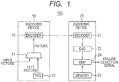
Fig. 1 is a block diagram showing a video encoding/decoding system according to an embodiment; -
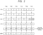
Fig. 2 is a schematic diagram showing a first failure detection operation of the video encoding/decoding system according to the embodiment; -
Fig. 3 is a schematic diagram showing a second failure detection operation of the video encoding/decoding system according to the embodiment; -
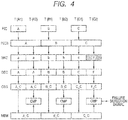
Fig. 4 is a schematic diagram showing a third failure detection operation of the video encoding/decoding system according to the embodiment; -
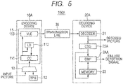
Fig. 5 is a block diagram showing the video encoding/decoding system according to an example; -
Fig. 6 is a block diagram showing a video encoding device according to an example; -
Fig. 7 is a block diagram showing a video decoding device according to the example; -
Fig. 8 is a timing diagram showing the second failure detection operation of the video encoding/decoding system according to the example; -
Fig. 9 is a timing diagram showing the effect of the second failure detection operation of the video encoding/decoding system according to the example; -
Fig. 10 is a timing diagram showing the effect of the second failure detection operation of the video encoding/decoding system according to the example; -
Fig. 11 is a timing diagram showing the third failure detection operation of the video encoding/decoding system according to the example; -
Fig. 12 is a timing diagram showing the third failure detection operation of the video encoding/decoding system according to the example; -
Fig. 13 is a timing diagram showing the operation that combines the first and second failure detection operations of the video encoding/decoding system according to an example; -
Fig. 14 is a timing diagram showing the operation with a combination of the first failure detection operation of the video encoding/decoding system according to the example; -
Fig. 15 is a timing diagram showing the operation with a combination of the first and third failure detection operations of the video encoding/decoding system according to an example; -
Fig. 16 is a block diagram showing a video encoding/decoding system according to Application Example 1; -
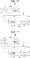
Fig. 17 is a block diagram showing a video encoding/decoding system according to Application Example 2; -
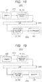
Fig. 18 is a block diagram showing a video encoding/decoding system according to Application Example 3; and -
Fig. 19 is a block diagram showing a video encoding/decoding system according to Application Example 4. - Hereinafter, the preferred embodiment, example, and applications will be described with reference to the accompanying drawings. Note, however, that in the following description the same components are denoted by the same reference numerals and the redundant description thereof may be omitted.
- First, a video encoding/decoding system according to an embodiment will be described with reference to
Figs. 1 to 4 .Fig. 1 is a block diagram showing the configuration of a video encoding/decoding system according to the embodiment.Fig. 2 is a schematic diagram showing an example of a first failure detection operation of the video encoding/decoding system according to the embodiment.Fig. 3 is a schematic diagram showing an example of a second failure detection operation of the video encoding/decoding system according to the embodiment.Fig. 4 is a schematic diagram showing an example of a third failure detection operation of the video encoding/decoding system according to the embodiment. - As shown in
Fig. 1 , a video encoding/decoding system 100 according to the embodiment includes avideo encoding device 10 and avideo decoding device 20. Thevideo encoding device 10 includes anencoding part 11 for ending an image. Thevideo decoding device 20 includes: a decodingpart 21 for decoding the encoded image; a check signal generation part (CSG) 22 for generating a check signal from the decoded image; astorage part 23 for storing the check signal; and a comparison part (CMP) 24 for comparing the check signal generated by the checksignal generation part 22 with the check signal stored in thestorage part 23. - It is preferable that the
video encoding device 10 further includes a diagnosticimage generation part 12 for generating a diagnostic image (TEST PICTURE), as well as a switchingcircuit 13 for switching between the input image (INPUT PICTURE) and the diagnostic image. - The video encoding/
decoding system 100 performs a failure detection operation (diagnosis) by one or a combination of the followings. - The
encoding part 11 encodes (compresses) a diagnostic image output from the diagnosticimage generation part 12 in a predetermined order, and transmits to thevideo decoding device 20. Thedecoding part 21 decodes (extends) the encoded image received from thevideo encoding device 10, and generates a check signal of the decoded image. Thecomparison part 24 compares the check signal generated by the checksignal generation part 22 with the expected value (check signal of the diagnostic image) which is stored in advance in thestorage part 23. If the comparison result is a mismatch, thecomparison part 24 determines that a failure has occurred, and outputs (or activates) the failure detection signal. - An example of the first failure detection operation will be described with reference to
Fig. 2 . It is assumed that failure detection operations from A image, B image, C image, D image, E image, and F image for diagnosis are T(A), T(B), T(C), T(D), T(E), and T(F). In T(A), the diagnostic image generation part (TPG) 12 outputs an A image for diagnosis. Then, the encoding part (ENC) 11 generates an a image by encoding the A image. The decoding part (DEC) 21 generates the A image by decoding the a image. Then, the check signal generation part (CSG) 22 generates a check signal (A_C) of the A image. The comparing part (CMP) 24 compares the check signal (A_C) of the A image, which is the expected value stored in the storage part (MEM) 23, with the check signal (A_C) of the A image that is generated by the checksignal generation part 22. In this case, the check signals (A_C) match, so that thecomparison part 24 does not output (or inactivates) the failure detection signal. Similarly, the check signals match in the operations from T (B) to T (E), so that thecomparison part 24 does not output (or inactivates) the failure detection signal. - In T(F), the diagnostic image generation part (TPG) 12 generates an F image for diagnosis. Then, the encoding part (ENC) 11 generates an f image by encoding the F image. Due to a failure in the decoding part (DEC) 21, the decoding part (DEC) 21 generates an R image by decoding the f image. Then, the check signal generation part (CSG) 22 generates a check signal (R_C) of the R image. The comparison part (CMP) 24 compares the check signal (F_C) of the F image, which is the expected value stored in the storage part (MEM) 23, with the check signal (R_C) of the R image that is generated by the check
signal generation part 22. In this case, the check signals do not match, so that thecomparison part 24 outputs (or activates) the failure detection signal. - The diagnostic
image generation part 12 randomly generates a diagnostic image. Theencoding part 11 encodes the output diagnostic image, and transmits the encoded image to thevideo decoding device 20. Thedecoding part 21 decodes the encoded image received from thevideo encoding device 10. Then, the checksignal generation part 22 generates a check signal of the decoded image. After the encoding-decoding operation is performed twice on the same diagnostic image, thecomparison part 24 detects a failure by checking a match between the first check signal of the decoded image stored in thestorage part 23, and the second check signal of the decoded image stored in thestorage part 23. If the comparison result is a mismatch, thecomparison part 24 determines that a failure has occurred and outputs (or activates) the failure detection signal. - An example of the second failure detection operation will be described with reference to
Fig. 3 . It is assumed that the first and second failure detection operations from the A image, B image, and C image for diagnosis are T(A1), T(A2), T(B1), T(B2), T(C1), and T(C2). In T(A1), the diagnostic image generation part (TPG) 12 generates an A image for diagnosis, and the encoding part (ENC) 11 generates an a image by encoding the A image. The decoding part (DEC) 21 generates the A image by decoding the a image. Then, the check signal generation part (CSG) 22 generates a check signal (A_C) of the A image and stores in the storage part (MEM) 23. In T(A2), the diagnostic image generation part (TPG) 12 outputs the A image for diagnosis, which is the same image as in T(A1). Then, the encoding part (ENC) 11 generates an a image by encoding the A image. The decoding part (DEC) 21 generates the A image by decoding the a image. Then, the check signal generation part (CSG) 22 generates the check signal (A_C) of the A image. The comparison part (CMP) 24 compares the first check signal of the A image that is stored in the storage part (MEM) 23 with the second check signal (A_C) of the A image that is generated by the checksignal generation part 22. In this case, the check signals (A_C) match, so that thecomparison part 24 does not output (or inactivates) the failure detection signal. Similarly, the check signals match in T(B2), so that thecomparison part 24 does not output (or inactivates) the failure detection signal. - In T(C1), the diagnostic image generation part (TPG) 12 generates a C image for diagnosis. Then, the encoding part (ENC) 11 generates a c image by encoding the C image. The decoding part (DEC) 21 generates the C image by decoding the c image. Then, the check signal generation part (CSG) 22 generates a check signal of the C image and stores in the storage part (MEM) 23. In T(C2), the diagnostic image generation part (TPG) 12 outputs the C image for diagnosis, which is the same image as in T(C1) . Then, due to a failure in the encoding part (ENC) 11, the encoding part (ENC) 11 generates an f image by encoding the C image. The decoding part (DEC) 21 generates the F image by decoding the f image. Then, the check signal generation part (CSG) 22 generates a check signal (F_C) of the F image. The comparison part (CMP) 24 compares the first check signal (C_C) of the C image that is stored in the storage part (MEM) 23 with the second check signal (F_C) of the F image that is generated by the check
signal generation part 22. In this case, the check signals do not match, so that thecomparison part 24 outputs (or activates) the failure detection signal. - Different from the first and second failure detection operations, the third failure detection operation performs failure detection by a normal video encoding/decoding operation (normal operation). In other words, in the normal operation, part or whole of the input image as well as encoding parameters are stored in the
encoding part 11, and a check signal of a decoded image is generated and stored in thestorage part 23. The same operation is performed again to obtain a check signal of the decoded image. Then, the obtained two check signals are compared by thecomparison part 24. If the comparison result is a mismatch, thecomparison part 24 determines that a failure has occurred. - An example of the third failure detection operation will be described with reference to
Fig. 4 . It is assumed that the first and second failure detection operations from the normal A image, B image and C image are T (A1), T(A2), T(B1), T(B2), T(C1), and T(C2). In T(A1), the encoding part (ENC) 11 generates an a image by encoding the input A image. Here, the image data or other information necessary for the second encoding is stored in an image storage part (PICB) not shown. The decoding part (DEC) 21 generates the A image by decoding the a image. Then, the check signal generating part (CSG) 22 generates a check signal (A_C) of the A image and stores in the storage part (MEM) 23. In T (A2), the encoding part (ENC) 11 generates an a image by encoding the A image stored in PICB. The decoding part (DEC) 21 generates the A image by decoding the a image. Then, the check signal generation part (CSG) 22 generates a check signal (A_C) of the A image. The comparison part (CMP) 24 compares the first check signal (A_C) of the A image that is stored in the storage part (MEM) 23, with the check signal (A_C) of the A image that is generated by the checksignal generation part 22. In this case, the check signals (A_C) match, so that thecomparison part 24 does not output (or inactivates) the failure detection signal. Similarly, the check signals match in T(B2), thecomparison part 24 does not output (or inactivates) the failure detection signal. - In T(C1), the encoding part (ENC) 11 generates a c image by encoding the input C image. Here, the image data or other information necessary for the second encoding is stored in PICB. The decoding part (DEC) 21 generates the C image by decoding the c image. Then, the check signal generation part (CSG) 22 generates a check signal (C_C) of the C image and stores in the storage part (MEM) 23. In T (C2), the encoding part (ENC) 11 generates an f image by encoding the C image stored in PICB due to a failure. The decoding part (DEC) 21 generates the F image by decoding the f image. Then, the check signal generation part (CSG) 22 generates a check signal (F_C) of the F image. The comparison part (CMP) 24 compares the first check signal (C_C) of the C image that is stored in the storage part (MEM) 23 with the second check signal (F_C) of the F image that is generated by the check
signal generation part 22. In this case, the check signals do not match, so that thecomparison part 24 outputs (or activates) the failure detection signal. - In the video encoding/
decoding system 100, it is possible to detect failure in all the paths from the image input part of theencoding part 11 of thevideo encoding device 10 to the image output part of thedecoding part 21 of thevideo decoding device 20. In addition, any additional information such as a check signal is not transmitted from thevideo encoding device 10, so that the extra bandwidth of the communication path (transmission path) is not consumed. - In the first failure detection operation, the expected value is the check signal whose size is smaller than the bit stream, so that the storage cost is low.
- In the second failure detection operation, the coverage of the failure detection is increased by the use of numerous diagnostic images. At the same time, there is no need to use expected values and the storage capacity of the
storage part 23 can be reduced. As a result, the cost of storing expected values is lower than that in the first failure detection operation. - In the third failure detection operation, as compared to the first and second failure detection operations, the operation exclusive for failure detection is not required, so that the power consumption is reduced. Further, different from the first and second failure detection operations, the failure detection is performed during the normal operation, making it possible to detect soft errors.
- Next, the configuration of a video encoding/decoding system according to an example will be described with reference to
Figs. 5 to 7 .Fig. 5 is a block diagram showing the configuration of a video encoding/decoding system according to an example.Fig. 6 is a block diagram showing the configuration of a video encoding device according to the example.Fig. 7 is a block diagram showing the configuration of a video decoding device according to the example. - As shown in
Fig. 5 , a video encoding/decoding system 100A according to an example includes: a video encoding device (ENCODING DEVICE) 10A; a transmission path (TRANSMISSION LINE) 30 on which the encoded image, which is the output of thevideo encoding device 10A, is transmitted; and a video decoding device (DECPDING DEVICE) 20A coupled to the transmission destination. Thevideo encoding device 10A includes anencoding part 11 for encoding an image, a diagnosticimage generation part 12 for generating a diagnostic image, and aswitching circuit 13 for switching between the input image and the diagnostic image generated by the diagnosticimage generation part 12. Theencoding part 11 includes a coefficient calculation unit (CC) 111, a local decoding image generation unit (LD) 112, and a variable length encoding unit (VLE) 113. Thevideo decoding device 20A includes adecoding part 21 for decoding the encoded image, a checksignal generation part 22A for generating a check sum, astorage part 23 for storing the check sum of the diagnostic image as well as the check sum generated by the checksignal generation part 22A, and acomparison part 24A for comparing the check sum generated by the checksignal generation part 22A with the check sum stored in thestorage part 23. Thedecoding part 21 outputs the decoded image (DECODED PICTURE) . Thetransmission path 30 can be a wired communication path or a wireless one. However, the wired communication path is preferable in terms of security. - As shown in
Fig. 6 , theencoding part 11 of thevideo encoding device 10A includes: thecoefficient calculation unit 111 including asubtractor 2, anencoder 4, amotion estimation unit 7, and a motion compensation unit (MC) 8; the local decodingimage generation unit 112 including a frame store (FS) 3, anadder 5, and apartial decoder 6; and the variablelength encoding unit 113. - The normal image and the diagnostic image are received by an
input node 1. Thesubtractor 2 generates the difference between the signal of theinput node 1 and the prediction signal from themotion compensation unit 8. Then, the difference is encoded by theencoder 4. The input to theframe store 3 is the sum of the prediction signal, which is generated by theadder 5, and the encoded differential signal decoded by thepartial decoder 6. - The prediction is achieved by delaying one frame, which is simply done by the
frame store 3. Themotion estimation unit 7 compares the frame of the image that is currently encoded with the previous frame in theframe store 3. Then, the area in which the target block is the most similar in the previous frame is identified with respect to each of the blocks obtained by dividing the current frame. The vector difference in the position between the identified area and the target block is called motion vector (MV) because it shows the movement of the object in the scene shown by the displayed image. The vector difference is supplied to themotion compensation unit 8. Themotion compensation unit 8 contributes to better prediction by shifting the identified area of the previous frame to the position of the related block in the current frame. As a result, the difference formed by thesubtractor 2 is smaller in average, allowing theencoder 4 to encode the image by using a lower rate than the case of larger difference. The variablelength encoding unit 113 generates a bit stream based on the output of theencoder 4 and on the motion vector (MV) and outputs to thetransmission path 30. - As shown in
Fig. 7 , thedecoding part 21 includes a decoder 6', a motion compensation unit 8', a frame store 3', and an adder 5'. First, the operation opposite to every encoding operation performed in theencoder 4, is performed in the decoder 6' to generate an inter-frame differential signal. The decoder 6' is similar to thedecoder 6. The inter-frame differential signal is then added to the prediction from the frame store 3' passing through the motion compensation in the motion compensation unit 8' that receives the motion vector (MV) from thevideo encoding device 10A. The output of the adder 5' forms an output of the decoding part and is supplied to the input of the frame store 3' . - Although not shown, it is also possible to provide a buffer in the output of the
video encoding device 10A and in the input of thevideo decoding device 20A, in order to transmit data over a fixed bit rate channel. - For example, the
video encoding device 10A and thevideo decoding device 20A are semiconductor devices each formed on a single semiconductor substrate. Both thevideo encoding device 10A and thevideo decoding device 20A may be formed on a single semiconductor substrate. In this case, the transmission side and the reception side use the same semiconductor device, in which the transmission side uses only the function of thevideo encoding device 10A and the reception side uses only the function of thevideo decoding device 20A. Note that each of thevideo encoding device 10A and thevideo decoding device 20A may not be formed on a single semiconductor substrate. Further, the encoding and decoding may be realized by software on the CPU. - Next, the failure detection operation of the video encoding/decoding system according to the example will be described with reference to
Figs. 8 to 12 .Fig. 8 is a timing diagram showing the second failure detection operation of the video encoding/decoding system according to the example.Figs. 9 and10 are timing diagrams for illustrating the effect of the second failure detection operation of the video encoding/decoding system according to the example.Fig. 11 is a timing diagram showing the third failure detection operation (an example using a part of the input image) of the video encoding/decoding system according to the example.Fig. 12 is a timing diagram showing the third failure detection operation (an example using a part of the input image by changing the position) of the video encoding/decoding system according to the example. - The video encoding/
decoding system 100A according to the example performs the same operation as the first, second, and third failure detection operations of the video encoding/decoding system according to the embodiment. The configuration or operation will be described more in detail below. - The
encoding part 11 encodes the diagnostic image output from the diagnosticimage generation part 12 and transmits to thevideo decoding device 20A. Thedecoding part 21 decodes the encoded image received from thevideo encoding device 10A. Then, the checksignal generation part 22A generates a check sum of the decoded image. Thecomparison part 24A detects a failure by comparing the check sum generated by the checksignal generation part 22A with the expected value (check sum) stored in thestorage part 23 in advance. If the comparison result is a mismatch, thecomparison part 24A determines that a failure has occurred and outputs (or activates) the failure detection signal. - The diagnostic image may be the data stored in a nonvolatile memory such as ROM or flash memory, or the data written in a nonvolatile memory, such as RAM, or a flash memory from the outside before operation, or the data that the diagnostic
image generation part 12 generates by a predetermined arithmetic operation. - The data for comparison is not limited to the check sum, and check signals such as hash values, such as MD5 (Message Digest 5) and SHA-1 (Secure Hash Algorithm 1), as well as a cyclic redundancy check (CRC) code may also be used. The check sum can also be generated from the image before de-blocking filter in H.264 (MPEG-4 AVC). It is also possible that both the expected value for generating a check sum from the decoded image, and the expected value for generating a check sum from the image before de-blocking filter are stored in the
storage unit 23. In this case, whether the check sum is generated from the decoded image or whether it is generated from the image before de-blocking filter may be switched according to the setting from the outside, or based on the signal and data transmitted from thevideo encoding device 10A. Note that the bit stream required for the failure detection operation has a data amount of at least about 1K bits, but the check sum has a data amount of about 100 bits. As a result, the storage cost can be reduced. - The diagnostic
image generation part 12 randomly generates a diagnostic image. Then, theencoding part 11 encodes the output diagnostic image and transmits to thevideo decoding device 20A. Thedecoding part 21 decodes the encoded image received from thevideo encoding device 10A. Then, the checksignal generation part 22A generates a check sum of the decoded image. The encoding-decoding operation is performed twice on the same diagnostic image. Then, thecomparison part 24A checks if there is a match between the first and second check sums stored in thestorage part 23 in order to perform a diagnosis. If the comparison result is a mismatch, thecomparison part 24A determines that a failure has occurred and outputs (or activates) the failure detection signal. - As shown in
Fig. 8 , it is assumed that the first encoding-decoding operation (failure detection operation) from the A image, which is the diagnostic image, is T(A1) and its second encoding-decoding operation (failure detection operation) is T(A2) . Further, it is assumed that the first encoding-decoding operation from the B image, which is the next diagnostic image, is T(B1) and its second encoding-decoding operation is T(B2). In this case, T(A1), T(B1), T(A2), and T(B2) are performed in this order. Note that the diagnostic video encoding/decoding operation is performed during the pause period of normal video encoding/decoding operation (normal operations such as PIC(N), P·IC(N+1), and so on). When the period in which the failure can be detected by the failure detection operation from the A image is P(A) and when the period in which failure can be detected by the failure detection operation from the B image is P(B), there is an overlap between P(A) and P(B). - On the other hand, as shown in
Figs. 9 and10 , when T(A1), T(A2), T(B1), and T(B2) are performed in this order, there is no overlap in each of the periods of P(A) and P (B) . As a result, a period (P(ND)) occurs in which failure may not be detected. By performing the failure detection operation in the order of this example, it is possible to eliminate the period (P(ND)) of not being able to detect failures. - The random generation method/algorithm can be arbitrary such as a linear feedback shift register (LFSR). Further, a plurality of predetermined data can be output periodically.
- The encoding-decoding may be performed multiple (three or more) times on the same diagnostic image. At this time, the operations can be performed in any order as long as there is an overlap in the periods in which failure can be detected by the failure detection operations from the respective images.
- In the second failure detection operation, failure detection is performed by the normal video encoding/decoding operation (normal operation) . A part or whole of the input image is used as the diagnostic image in place of using the output of the diagnostic
image generation part 12. In other words, in the normal video encoding/decoding operation, a part or whole of the input image as well as the encoding parameters are stored in the storage part (PICB), and the decoding result (the check sum generated from the decoded image) is stored in the storage part 34. Then, the same operation is performed again to obtain the decoding result (check sum). Thecomparison part 24A compares the obtained two check sums. If the comparison result is a mismatch, thecomparison part 24A determines that a failure has occurred. - As shown in
Fig. 11 , PIC (N) and T (N1), PIC (N+1) and T((N+1)1), T(N2), PIC (N+2) and T((N+2)1), T((N+1)2) are performed in this order. Here, the normal operation with respect to the N frame is PIC(N), its first failure detection operation is T(N1), its second failure detection operation is T(N2). Then, the normal operation with respect to the next N+1 frame is PIC(N+1), its first failure detection operation is T((N+1)1), and its second failure detection operation is T((N+1)2). Further, the normal operation with respect to the N+2 frame is PIC(N+2), its first failure detection operation is T((N+2)1), and its second failure detection operation is T((N+2)2). T(N1), T((N+1)1), and ((N+1)2) are performed by using a part of PIC(N), PIC N+1), and PIC (N+2), respectively. When the periods in which failure can be detected by T(N1) and T(N2) are P (N) and T((N+1)1)and when the period in which failure can be detected by T((N+1)2) is P (N+1), there is an overlap between P(N) and P (N+1) similarly to the case of the second failure detection operation. Thus, it is possible to eliminate the period in which failure may not be detected. - As shown in
Fig. 12 , when a part of the input image is used, the failure detection operation may be performed over several frames by changing positions. T (Nall) is the first failure detection operation of PIC(N), and uses the whole of the input image. However, the second failure detection operation is performed separately, for example, three times. T(N12) of the second failure detection operation with respect to T(N11), which is a part of the first failure detection operation, is performed between PIC(N+1) and PIC(N+2). T(N22) of the second failure detection operation with respect to T(N21), which is a part of the first failure detection operation, is performed after PIC(N+2). T(N32) of the second failure detection operation with respect to T(N31), which is a part of the first failure detection operation, is performed after the normal operation on the N+3 frame. In this way, the failure detection operation of the whole input image of the Nth frame is completed. - When only the third failure detection operation is performed, the output of the diagnostic
image generation part 12 is not used, so that the video encoding/decoding system 1 may not include the diagnosticimage generation part 12. - The self-diagnosis function of the video encoding/
decoding system 100A performs failure detection operation by one or a combination of the failure detection operations (1) to (3). Several examples will be described with reference toFigs. 13 to 15. Fig. 13 is a timing diagram showing the operation with a combination of the first and second failure detection operations of the video encoding/decoding system according to the example.Fig. 14 is a timing diagram showing the operation with a combination of the first failure detection operation of the video encoding/decoding system according to the example.Fig. 15 is a timing diagram showing the operation with a combination of the first and third failure detection operations of the video encoding/decoding system according to the example. - As shown in
Fig. 13 , the first failure detection operation (1st FAILURE DETCTION) is performed before the start of the video transmission. After the start of the video transmission, the second failure detection operation (2nd FAILURE DETECTION) is performed during the pause period of the encoding-decoding operation. The memory capacity of the diagnosticimage generation part 12 or the hardware capacity of the computing unit, or the like, must be increased in order to obtain sufficient coverage by only the first failure detection operation. In addition, the memory capacity of thestorage part 23 in which the corresponding expected value is stored is large. On the other hand, if a failure occurs before the period in which the first failure can be detected (for example, before power on or other event), the failure may not be detected by only the second failure detection operation. By performing the second failure detection operation after the first failure detection operation, it is possible to reduce the period of not being able to detect failures and to reduce the diagnosticimage generation part 12 as well as thestorage part 23. Further, the second failure detection operation can increase the coverage, so that the number of times of the first failure detection operation, namely, the diagnosis time before video transmission can be reduced. - The first failure detection operation may be performed only once just after power on. It is also possible to perform, as shown in
Fig. 14 , the first failure detection operation with an arbitrary interval, in place of the second failure detection operation, during the pause period of the encoding-decoding operation after the start of the video transmission. This makes it possible to reduce the diagnosis time before the video transmission. - As shown in
Fig. 15 , the respective failure detection operations can be performed as follows: The first failure detection operation is performed before the start of the video transmission. The first operation of the third failure detection operation (3rd FAILURE DETECTION) is performed during the normal video encoding/decoding operation. Then, the second encoding-decoding operation of the third failure detection operation is performed during the pause period of the encoding-decoding operation. Similarly to the case of performing only the second failure detection operation, if a failure occurs before the period in which the first failure can be detected (for example, before power on or other event), the failure may not be detected by only the third failure detection operation. By performing the third failure detection operation after the first failure detection operation, it is possible to reduce the period of not being able to detect failures and to reduce the diagnosticimage generation part 12 as well as thestorage part 23. Further, the third failure detection operation can increase the coverage, so that the number of times of the first failure detection operation, the diagnosis time before video transmission can be reduced. - Further, the pause period of the encoding-decoding operation can be an arbitrary timing as long as it is not the period of performing the normal video encoding/decoding operation, such as the vertical blanking period between frames, the horizontal blanking period between lines, or the period that is set by forcibly stopping the encoding-decoding operation.
- The first and second failure detection operations can be performed not only during the pause period of the encoding-decoding operation, but also during the normal video encoding-decoding operation period (normal operation period) . In the input of the encoding process in the
video encoding device 10A, the switching between the input image for the normal operation and the diagnostic image for the failure detection operation is performed in a predetermined unit of image area. For example, an image obtained by a fisheye lens that covers a wide range is typically subject to the distortion correction process to cut out the four corners, and is not used for display and image processing. When such an image is the input image, it is necessary to input it by switching a predetermined image area, such as 20x20 pixels on the left top corner, of the unwanted image areas, to the diagnostic image. - Compared to performing the failure detection operation during the pause period of the encoding-decoding operation, there is no need to perform the operation dedicated to failure detection and the power consumption is reduced.
- The preferred embodiment and example can be applied to the video encoding/decoding device, the device having the video encoding decoding function, and the system using the same. For example, the preferred embodiment and example can be applied to in-vehicle cameras, in-vehicle periphery monitoring systems, in-vehicle driver support systems, in-vehicle automated driving systems, in-vehicle navigation systems, drive recorders, display audio systems, monitoring camera systems, network cameras, smartphones, tablets, digital cameras, camcorders, set top boxes (STB), Blu-ray Disc (BD) recorders, and the like.
- The first to fourth applications (Application Examples 1 to 4) of the preferred embodiment and example will be described with reference to
Figs. 16 to 19 .Fig. 16 is a block diagram showing the configuration of a video encoding/decoding system according to Application Example 1.Fig. 17 is a block diagram showing the configuration of a video encoding/decoding system according to Application Example 2.Fig. 18 is a block diagram showing the configuration of a video encoding/decoding system according to Application Example 3.Fig. 19 is a block diagram showing the configuration of a video encoding/decoding system according to Application Example 4. - As shown in
Fig. 16 , a video encoding/decoding system 200A according to Application Example 1 includes an in-vehicle camera 210A and acontrol unit 220A, which is a system in which the in-vehicle camera 210A and thecontrol unit 220A are coupled to an in-vehicle local area network (LAN) 230A such as Ethernet Audio Video Bridging (AVB) . The in-vehicle camera 210A includes an imaging device (CAMERA) 40A and a video encoding device (ENCODING DEVICE) 10, 10A. Thecontrol unit 220A includes a video decoding device (DECODING DEVICE) 20, 20A and a control unit (CONTROLLER) 50A for controlling driver support and automated driving or other functions, based on the decoded image. The video encoding/decoding system 200A may further include a display device for displaying the decoded image. - As shown in
Fig. 17 , a video encoding/decoding system 200B according to Application Example 2 includes an in-vehicle camera 210B and adisplay unit 220B, which is a system in which the in-vehicle camera 210B and thedisplay unit 220B are coupled by an in-vehicle LAN 230B such as Ethernet AVB. The in-vehicle camera 210B includes animaging device 40B and avideo encoding device display unit 220B includes avideo decoding device - As shown in
Fig. 18 , a video encoding/decoding system 200C according to Application Example 3 includes amonitoring camera module 210C and acontrol unit 220C, which is a monitoring camera system in which themonitoring camera module 210C and thecontrol unit 220C are coupled byLAN 230C such as Ethernet. Themonitoring camera module 210C includes animaging device 40C and a video encoding/decoding device control unit 220C includes acontrol device 50C and avideo decoding device decoding system 220C may further include a display device for display the decoded image. - As shown in
Fig. 19 , a video encoding/decoding system 200D according to Application Example 4 includes amonitoring camera module 210D and arecorder 220D, which is a monitoring camera system in which the monitoring camera module 201A and therecorder 220D are coupled byLAN 230D such as Ethernet. Themonitoring camera module 210D includes animaging device 40D and avideo encoding device recorder 220D includes avideo decoding device decoding system 220D may further include a display device for displaying the decoded image. - In the video encoding/decoding systems according to Application Examples 1 to 4, it is possible to detect failure in all the paths from the image input part of the video encoding device to the image output part of the video decoding device. As a result, it is possible to improve safety and reliability.
- The invention made by the present inventors has been concretely described based on the preferred embodiment, example, and applications.
Claims (3)
- A video encoding/decoding system (100, 100A) comprising:a video encoding device (10, 10A); anda video decoding device (20, 20A),wherein the video encoding device includes:a diagnostic image generation part (12) for generating a first diagnostic image (A) and a second diagnostic image (B), and outputting the first diagnostic image (A) in a first failure detection operation T(A1), the second diagnostic image in a second failure detection operation T(B1), the first diagnostic image (A) in a third failure detection operation T(A2), the second diagnostic image in a fourth failure detection operation T(B2), the failure detection operations T(A1), T(B1), T(A2) and T(B2) being performed in this order;a switching part (13) for outputting either a diagnostic image, being the first diagnostic image or the second diagnostic image, from the diagnostic image generation part (12), or an input image; andan encoding part (11) for encoding an image from the switching part (13), wherein the video decoding device includes:a decoding part (21) for decoding the image encoded in the encoding part (11);a check signal generation part (22, 22A) for generating a check signal of the decoded first diagnostic image (A) in the first failure detection operation T(A1), a check signal of the decoded second diagnostic image (B) in the second failure detection operation T(B1), a check signal of the decoded first diagnostic image (A) in the third failure detection operation T(A2), and a check signal of the decoded second diagnostic image (B) in the fourth failure detection operation T(B2);a storage part (23) for storing the check signal generated by the check signal generation part (22, 22A) in the first failure detection operation T(A1) and the check signal generated by the check signal generation part (22, 22A) in the second failure detection operation T(B1); anda comparison part (24, 24A) for comparing the check signal stored in the storage part (23) in the first failure detection operation T(A1) with the check signal generated by the check signal generation part (22, 22A) in the third failure detection operation T(A2), and comparing the check signal stored in the storage part (23) in the second failure detection operation T(B1) with the check signal generated by the check signal generation part (22, 22A) in the fourth failure detection operation T(B2),wherein an encoding and decoding operation of an input image or part of an input image takes place between the first failure detection operation T(A1) and the second failure detection operation T(B1), between the second failure detection operation T(B1) and the third failure detection operation T(A2), and between the third failure detection operation T(A2) and the fourth failure detection operation T(B2).
- A video encoding/decoding system according to Claim 1,
wherein the check signal is a check sum. - A diagnosis method of a video encoding/decoding system, comprising:a diagnostic image generation step of generating a first diagnostic image (A) and a second diagnostic image (B), and outputting the first diagnostic image (A) in a first failure detection operation T(A1), the second diagnostic image in a second failure detection operation T(B1), the first diagnostic image (A) in a third failure detection operation T(A2), the second diagnostic image in a fourth failure detection operation T(B2), the failure detection operations T(A1), T(B1), T(A2) and T(B2) being performed in this order;a switching step of outputting either a diagnostic image, being the first diagnostic image or the second diagnostic image, generated at the diagnostic image generation step, or an input image;an encoding step of encoding an image outputted at the switching step;a decoding step of decoding the image encoded at the encoding step;a check signal generation step of generating a check signal of the decoded first diagnostic image (A) in the first failure detection operation T(A1), a check signal of the decoded second diagnostic image (B) in the second failure detection operation T(B1), a check signal of the decoded first diagnostic image (A) in the third failure detection operation T(A2), and a check signal of the decoded second diagnostic image (B) in the fourth failure detection operation T(B2);a storing step of storing the check signal generated at the check signal generation step in the first failure detection operation T(A1) and storing the check signal generated at the check signal generation step in the second failure detection operation T(B1); anda comparison step of comparing the check signal stored at the storing step in the first failure detection operation T(A1) with the check signal generated at the check signal generation step in the third failure detection operation T(A2), and comparing the check signal stored at the storing step in the second failure detection operation T(B1) with the check signal generated at the check signal generation step in the fourth failure detection operation T(B2),wherein an encoding and decoding operation of an input image or part of an input image takes place between the first failure detection operation T(A1) and the second failure detection operation T(B1), between the second failure detection operation T(B1) and the third failure detection operation T(A2), and between the third failure detection operation T(A2) and the fourth failure detection operation T(B2).
Applications Claiming Priority (1)
| Application Number | Priority Date | Filing Date | Title |
|---|---|---|---|
| JP2015001530A JP6468846B2 (en) | 2015-01-07 | 2015-01-07 | Image encoding / decoding system and diagnostic method thereof |
Publications (2)
| Publication Number | Publication Date |
|---|---|
| EP3043562A1 EP3043562A1 (en) | 2016-07-13 |
| EP3043562B1 true EP3043562B1 (en) | 2021-05-19 |
Family
ID=55070740
Family Applications (1)
| Application Number | Title | Priority Date | Filing Date |
|---|---|---|---|
| EP15201855.2A Active EP3043562B1 (en) | 2015-01-07 | 2015-12-22 | Video encoding/decoding system and diagnosis method thereof |
Country Status (4)
| Country | Link |
|---|---|
| US (2) | US10051280B2 (en) |
| EP (1) | EP3043562B1 (en) |
| JP (1) | JP6468846B2 (en) |
| CN (1) | CN105763872B (en) |
Families Citing this family (8)
| Publication number | Priority date | Publication date | Assignee | Title |
|---|---|---|---|---|
| WO2018037525A1 (en) * | 2016-08-25 | 2018-03-01 | Necディスプレイソリューションズ株式会社 | Self-diagnostic imaging method, self-diagnostic imaging program, display device, and self-diagnostic imaging system |
| CN106534948B (en) * | 2016-11-23 | 2019-07-09 | 杭州当虹科技股份有限公司 | Audio frequency and video compiles transcoding issues fast-check method and system |
| JP2018107588A (en) * | 2016-12-26 | 2018-07-05 | ルネサスエレクトロニクス株式会社 | Image processing device and semiconductor device |
| GB2568037B (en) * | 2017-10-27 | 2022-08-03 | Displaylink Uk Ltd | Compensating for interruptions in a wireless connection |
| CN109413417B (en) * | 2018-12-17 | 2020-12-04 | 南京普物科技有限公司 | System and method for detecting interactive television service quality |
| CN111614952A (en) * | 2019-02-25 | 2020-09-01 | 北京地平线机器人技术研发有限公司 | Method and device for detecting reliability of image transmission channel |
| CN112655200B (en) * | 2020-08-24 | 2022-09-16 | 华为技术有限公司 | Signal sending method and device |
| CN113422949A (en) * | 2021-06-18 | 2021-09-21 | 展讯通信(天津)有限公司 | Method and device for positioning image processing problem |
Citations (2)
| Publication number | Priority date | Publication date | Assignee | Title |
|---|---|---|---|---|
| US20020091966A1 (en) * | 1999-07-19 | 2002-07-11 | Barton James M. | Self-test electronic assembly and test system |
| US7082557B2 (en) * | 2003-06-09 | 2006-07-25 | Lsi Logic Corporation | High speed serial interface test |
Family Cites Families (19)
| Publication number | Priority date | Publication date | Assignee | Title |
|---|---|---|---|---|
| US4718065A (en) * | 1986-03-31 | 1988-01-05 | Tandem Computers Incorporated | In-line scan control apparatus for data processor testing |
| JPH01243796A (en) * | 1988-03-25 | 1989-09-28 | Mitsubishi Electric Corp | Picture encoding and transmitting device |
| JPH08275161A (en) * | 1995-03-30 | 1996-10-18 | Oki Electric Ind Co Ltd | Image converter |
| JPH096943A (en) * | 1995-06-19 | 1997-01-10 | Hitachi Denshi Ltd | Fault diagnosing method for image processor |
| US5778008A (en) * | 1995-05-10 | 1998-07-07 | Hitachi Denshi Kabushiki Kaisha | Fault diagnosis method of television camera apparatus |
| US6281929B1 (en) * | 1997-09-23 | 2001-08-28 | Zenith Electronics Corporation | Testing arrangement for decoders |
| JP2000209304A (en) * | 1999-01-13 | 2000-07-28 | Mitsubishi Electric Corp | Self-monitoring coding device and its self-monitoring method |
| KR20050040448A (en) * | 2003-10-28 | 2005-05-03 | 삼성전자주식회사 | Method for video decording with error detection, and apparatus for the same |
| US7231587B2 (en) * | 2004-03-29 | 2007-06-12 | Lsi Corporation | Embedded picture PSNR/CRC data in compressed video bitstream |
| JP2006128905A (en) * | 2004-10-27 | 2006-05-18 | Matsushita Electric Ind Co Ltd | Digital video data inspection device, inspection system, and semiconductor device |
| JP4485921B2 (en) | 2004-11-18 | 2010-06-23 | 池上通信機株式会社 | Image recording device |
| CN101107864A (en) * | 2005-01-24 | 2008-01-16 | 汤姆森许可贸易公司 | Video error detection technique using a CRC parity code |
| JP4773731B2 (en) * | 2005-03-08 | 2011-09-14 | 富士通セミコンダクター株式会社 | Codec software test apparatus and codec software test method |
| EP1732331A1 (en) * | 2005-06-08 | 2006-12-13 | BRITISH TELECOMMUNICATIONS public limited company | Video coding |
| US7752511B2 (en) * | 2006-08-08 | 2010-07-06 | Siemens Industry, Inc. | Devices, systems, and methods regarding a PLC system fault |
| JP2008118297A (en) * | 2006-11-01 | 2008-05-22 | Matsushita Electric Ind Co Ltd | Digital video data test system and semiconductor device |
| EP2509332B1 (en) * | 2011-04-04 | 2015-12-30 | AGUSTAWESTLAND S.p.A. | Automatic test system for digital display systems |
| US8671333B2 (en) * | 2011-06-29 | 2014-03-11 | Lsi Corporation | Adaptive encoding and decoding for error protected packet-based frames |
| US8730330B2 (en) * | 2011-07-25 | 2014-05-20 | Aptina Imaging Corporation | Image sensors with dark pixels for real-time verification of imaging systems |
-
2015
- 2015-01-07 JP JP2015001530A patent/JP6468846B2/en active Active
- 2015-10-30 US US14/928,735 patent/US10051280B2/en active Active
- 2015-12-03 CN CN201510875698.6A patent/CN105763872B/en active Active
- 2015-12-22 EP EP15201855.2A patent/EP3043562B1/en active Active
-
2018
- 2018-08-02 US US16/053,244 patent/US10638148B2/en active Active
Patent Citations (2)
| Publication number | Priority date | Publication date | Assignee | Title |
|---|---|---|---|---|
| US20020091966A1 (en) * | 1999-07-19 | 2002-07-11 | Barton James M. | Self-test electronic assembly and test system |
| US7082557B2 (en) * | 2003-06-09 | 2006-07-25 | Lsi Logic Corporation | High speed serial interface test |
Also Published As
| Publication number | Publication date |
|---|---|
| EP3043562A1 (en) | 2016-07-13 |
| US20160198174A1 (en) | 2016-07-07 |
| CN105763872A (en) | 2016-07-13 |
| JP6468846B2 (en) | 2019-02-13 |
| US10638148B2 (en) | 2020-04-28 |
| CN105763872B (en) | 2019-06-14 |
| US20180343461A1 (en) | 2018-11-29 |
| US10051280B2 (en) | 2018-08-14 |
| JP2016127520A (en) | 2016-07-11 |
Similar Documents
| Publication | Publication Date | Title |
|---|---|---|
| EP3043562B1 (en) | Video encoding/decoding system and diagnosis method thereof | |
| US10771818B2 (en) | Method and apparatus for determining the severity of corruption in a picture | |
| US20100150230A1 (en) | Video coding system using sub-channels and constrained prediction references to protect against data transmission errors | |
| JP5598335B2 (en) | Data receiving apparatus, data transmitting apparatus, data receiving method, and data transmitting method | |
| JP2008546338A (en) | Video coding | |
| JP4860958B2 (en) | Video transmission device having active and standby systems | |
| US20160165171A1 (en) | Method and device for inserting a graphical overlay in a video stream | |
| JP2014011572A5 (en) | Moving picture predictive decoding apparatus, method and program | |
| JP7346518B2 (en) | Image processing devices, cameras, and methods for encoding sequences of video images | |
| US9723314B2 (en) | Flicker reduction circuit and method for compressed video transmission | |
| US20040105019A1 (en) | Camera equipment | |
| US8270497B2 (en) | Complementing bitstream error and decoding | |
| US20060182182A1 (en) | Image decoding apparatus and memory management unit | |
| US10645419B2 (en) | System encoder and decoder for verification of image sequence | |
| KR101850930B1 (en) | Collective camera video monitoring device | |
| KR100551366B1 (en) | Watch dog apparatus and method in digital video recorder | |
| US11968383B2 (en) | Quality-sparing code burn-in for video | |
| CN114531583A (en) | Method and device for checking the completeness of display content during the transmission of vehicle display information | |
| JPH0472985A (en) | Frame interpolation system | |
| JP2007053429A (en) | Video signal switching apparatus | |
| JP4555186B2 (en) | Digital video decoding apparatus and digital video decoding method | |
| JP2503556B2 (en) | Image coding transmission device operation test method | |
| WO2017203555A1 (en) | Encoding device, photographing device, and program | |
| JP2001078198A (en) | Error concealment control method, coder and image signal transmission system | |
| KR100555877B1 (en) | Method for changing data rate of security image data according to motion detecting between dvr system and remote pc |
Legal Events
| Date | Code | Title | Description |
|---|---|---|---|
| PUAI | Public reference made under article 153(3) epc to a published international application that has entered the european phase |
Free format text: ORIGINAL CODE: 0009012 |
|
| AK | Designated contracting states |
Kind code of ref document: A1 Designated state(s): AL AT BE BG CH CY CZ DE DK EE ES FI FR GB GR HR HU IE IS IT LI LT LU LV MC MK MT NL NO PL PT RO RS SE SI SK SM TR |
|
| AX | Request for extension of the european patent |
Extension state: BA ME |
|
| STAA | Information on the status of an ep patent application or granted ep patent |
Free format text: STATUS: REQUEST FOR EXAMINATION WAS MADE |
|
| 17P | Request for examination filed |
Effective date: 20170113 |
|
| RBV | Designated contracting states (corrected) |
Designated state(s): AL AT BE BG CH CY CZ DE DK EE ES FI FR GB GR HR HU IE IS IT LI LT LU LV MC MK MT NL NO PL PT RO RS SE SI SK SM TR |
|
| STAA | Information on the status of an ep patent application or granted ep patent |
Free format text: STATUS: EXAMINATION IS IN PROGRESS |
|
| 17Q | First examination report despatched |
Effective date: 20200214 |
|
| GRAP | Despatch of communication of intention to grant a patent |
Free format text: ORIGINAL CODE: EPIDOSNIGR1 |
|
| STAA | Information on the status of an ep patent application or granted ep patent |
Free format text: STATUS: GRANT OF PATENT IS INTENDED |
|
| RIC1 | Information provided on ipc code assigned before grant |
Ipc: H04N 19/46 20140101ALI20201113BHEP Ipc: H04N 19/65 20140101AFI20201113BHEP Ipc: H04N 19/89 20140101ALI20201113BHEP Ipc: H04N 17/00 20060101ALI20201113BHEP Ipc: H04N 19/44 20140101ALI20201113BHEP |
|
| INTG | Intention to grant announced |
Effective date: 20201217 |
|
| GRAS | Grant fee paid |
Free format text: ORIGINAL CODE: EPIDOSNIGR3 |
|
| GRAA | (expected) grant |
Free format text: ORIGINAL CODE: 0009210 |
|
| STAA | Information on the status of an ep patent application or granted ep patent |
Free format text: STATUS: THE PATENT HAS BEEN GRANTED |
|
| AK | Designated contracting states |
Kind code of ref document: B1 Designated state(s): AL AT BE BG CH CY CZ DE DK EE ES FI FR GB GR HR HU IE IS IT LI LT LU LV MC MK MT NL NO PL PT RO RS SE SI SK SM TR |
|
| REG | Reference to a national code |
Ref country code: GB Ref legal event code: FG4D |
|
| REG | Reference to a national code |
Ref country code: CH Ref legal event code: EP |
|
| REG | Reference to a national code |
Ref country code: DE Ref legal event code: R096 Ref document number: 602015069384 Country of ref document: DE |
|
| REG | Reference to a national code |
Ref country code: AT Ref legal event code: REF Ref document number: 1395142 Country of ref document: AT Kind code of ref document: T Effective date: 20210615 |
|
| REG | Reference to a national code |
Ref country code: IE Ref legal event code: FG4D |
|
| REG | Reference to a national code |
Ref country code: LT Ref legal event code: MG9D |
|
| REG | Reference to a national code |
Ref country code: AT Ref legal event code: MK05 Ref document number: 1395142 Country of ref document: AT Kind code of ref document: T Effective date: 20210519 |
|
| REG | Reference to a national code |
Ref country code: NL Ref legal event code: MP Effective date: 20210519 |
|
| PG25 | Lapsed in a contracting state [announced via postgrant information from national office to epo] |
Ref country code: FI Free format text: LAPSE BECAUSE OF FAILURE TO SUBMIT A TRANSLATION OF THE DESCRIPTION OR TO PAY THE FEE WITHIN THE PRESCRIBED TIME-LIMIT Effective date: 20210519 Ref country code: LT Free format text: LAPSE BECAUSE OF FAILURE TO SUBMIT A TRANSLATION OF THE DESCRIPTION OR TO PAY THE FEE WITHIN THE PRESCRIBED TIME-LIMIT Effective date: 20210519 Ref country code: BG Free format text: LAPSE BECAUSE OF FAILURE TO SUBMIT A TRANSLATION OF THE DESCRIPTION OR TO PAY THE FEE WITHIN THE PRESCRIBED TIME-LIMIT Effective date: 20210819 Ref country code: AT Free format text: LAPSE BECAUSE OF FAILURE TO SUBMIT A TRANSLATION OF THE DESCRIPTION OR TO PAY THE FEE WITHIN THE PRESCRIBED TIME-LIMIT Effective date: 20210519 Ref country code: HR Free format text: LAPSE BECAUSE OF FAILURE TO SUBMIT A TRANSLATION OF THE DESCRIPTION OR TO PAY THE FEE WITHIN THE PRESCRIBED TIME-LIMIT Effective date: 20210519 |
|
| PG25 | Lapsed in a contracting state [announced via postgrant information from national office to epo] |
Ref country code: IS Free format text: LAPSE BECAUSE OF FAILURE TO SUBMIT A TRANSLATION OF THE DESCRIPTION OR TO PAY THE FEE WITHIN THE PRESCRIBED TIME-LIMIT Effective date: 20210919 Ref country code: LV Free format text: LAPSE BECAUSE OF FAILURE TO SUBMIT A TRANSLATION OF THE DESCRIPTION OR TO PAY THE FEE WITHIN THE PRESCRIBED TIME-LIMIT Effective date: 20210519 Ref country code: GR Free format text: LAPSE BECAUSE OF FAILURE TO SUBMIT A TRANSLATION OF THE DESCRIPTION OR TO PAY THE FEE WITHIN THE PRESCRIBED TIME-LIMIT Effective date: 20210820 Ref country code: SE Free format text: LAPSE BECAUSE OF FAILURE TO SUBMIT A TRANSLATION OF THE DESCRIPTION OR TO PAY THE FEE WITHIN THE PRESCRIBED TIME-LIMIT Effective date: 20210519 Ref country code: RS Free format text: LAPSE BECAUSE OF FAILURE TO SUBMIT A TRANSLATION OF THE DESCRIPTION OR TO PAY THE FEE WITHIN THE PRESCRIBED TIME-LIMIT Effective date: 20210519 Ref country code: PT Free format text: LAPSE BECAUSE OF FAILURE TO SUBMIT A TRANSLATION OF THE DESCRIPTION OR TO PAY THE FEE WITHIN THE PRESCRIBED TIME-LIMIT Effective date: 20210920 Ref country code: NO Free format text: LAPSE BECAUSE OF FAILURE TO SUBMIT A TRANSLATION OF THE DESCRIPTION OR TO PAY THE FEE WITHIN THE PRESCRIBED TIME-LIMIT Effective date: 20210819 Ref country code: PL Free format text: LAPSE BECAUSE OF FAILURE TO SUBMIT A TRANSLATION OF THE DESCRIPTION OR TO PAY THE FEE WITHIN THE PRESCRIBED TIME-LIMIT Effective date: 20210519 Ref country code: ES Free format text: LAPSE BECAUSE OF FAILURE TO SUBMIT A TRANSLATION OF THE DESCRIPTION OR TO PAY THE FEE WITHIN THE PRESCRIBED TIME-LIMIT Effective date: 20210519 |
|
| PG25 | Lapsed in a contracting state [announced via postgrant information from national office to epo] |
Ref country code: NL Free format text: LAPSE BECAUSE OF FAILURE TO SUBMIT A TRANSLATION OF THE DESCRIPTION OR TO PAY THE FEE WITHIN THE PRESCRIBED TIME-LIMIT Effective date: 20210519 |
|
| PG25 | Lapsed in a contracting state [announced via postgrant information from national office to epo] |
Ref country code: SK Free format text: LAPSE BECAUSE OF FAILURE TO SUBMIT A TRANSLATION OF THE DESCRIPTION OR TO PAY THE FEE WITHIN THE PRESCRIBED TIME-LIMIT Effective date: 20210519 Ref country code: SM Free format text: LAPSE BECAUSE OF FAILURE TO SUBMIT A TRANSLATION OF THE DESCRIPTION OR TO PAY THE FEE WITHIN THE PRESCRIBED TIME-LIMIT Effective date: 20210519 Ref country code: DK Free format text: LAPSE BECAUSE OF FAILURE TO SUBMIT A TRANSLATION OF THE DESCRIPTION OR TO PAY THE FEE WITHIN THE PRESCRIBED TIME-LIMIT Effective date: 20210519 Ref country code: CZ Free format text: LAPSE BECAUSE OF FAILURE TO SUBMIT A TRANSLATION OF THE DESCRIPTION OR TO PAY THE FEE WITHIN THE PRESCRIBED TIME-LIMIT Effective date: 20210519 Ref country code: EE Free format text: LAPSE BECAUSE OF FAILURE TO SUBMIT A TRANSLATION OF THE DESCRIPTION OR TO PAY THE FEE WITHIN THE PRESCRIBED TIME-LIMIT Effective date: 20210519 Ref country code: RO Free format text: LAPSE BECAUSE OF FAILURE TO SUBMIT A TRANSLATION OF THE DESCRIPTION OR TO PAY THE FEE WITHIN THE PRESCRIBED TIME-LIMIT Effective date: 20210519 |
|
| REG | Reference to a national code |
Ref country code: DE Ref legal event code: R097 Ref document number: 602015069384 Country of ref document: DE |
|
| PLBE | No opposition filed within time limit |
Free format text: ORIGINAL CODE: 0009261 |
|
| STAA | Information on the status of an ep patent application or granted ep patent |
Free format text: STATUS: NO OPPOSITION FILED WITHIN TIME LIMIT |
|
| 26N | No opposition filed |
Effective date: 20220222 |
|
| PG25 | Lapsed in a contracting state [announced via postgrant information from national office to epo] |
Ref country code: IS Free format text: LAPSE BECAUSE OF FAILURE TO SUBMIT A TRANSLATION OF THE DESCRIPTION OR TO PAY THE FEE WITHIN THE PRESCRIBED TIME-LIMIT Effective date: 20210919 Ref country code: AL Free format text: LAPSE BECAUSE OF FAILURE TO SUBMIT A TRANSLATION OF THE DESCRIPTION OR TO PAY THE FEE WITHIN THE PRESCRIBED TIME-LIMIT Effective date: 20210519 |
|
| PG25 | Lapsed in a contracting state [announced via postgrant information from national office to epo] |
Ref country code: MC Free format text: LAPSE BECAUSE OF FAILURE TO SUBMIT A TRANSLATION OF THE DESCRIPTION OR TO PAY THE FEE WITHIN THE PRESCRIBED TIME-LIMIT Effective date: 20210519 Ref country code: IT Free format text: LAPSE BECAUSE OF FAILURE TO SUBMIT A TRANSLATION OF THE DESCRIPTION OR TO PAY THE FEE WITHIN THE PRESCRIBED TIME-LIMIT Effective date: 20210519 |
|
| REG | Reference to a national code |
Ref country code: CH Ref legal event code: PL |
|
| GBPC | Gb: european patent ceased through non-payment of renewal fee |
Effective date: 20211222 |
|
| REG | Reference to a national code |
Ref country code: BE Ref legal event code: MM Effective date: 20211231 |
|
| PG25 | Lapsed in a contracting state [announced via postgrant information from national office to epo] |
Ref country code: LU Free format text: LAPSE BECAUSE OF NON-PAYMENT OF DUE FEES Effective date: 20211222 Ref country code: IE Free format text: LAPSE BECAUSE OF NON-PAYMENT OF DUE FEES Effective date: 20211222 Ref country code: GB Free format text: LAPSE BECAUSE OF NON-PAYMENT OF DUE FEES Effective date: 20211222 |
|
| PG25 | Lapsed in a contracting state [announced via postgrant information from national office to epo] |
Ref country code: FR Free format text: LAPSE BECAUSE OF NON-PAYMENT OF DUE FEES Effective date: 20211231 Ref country code: BE Free format text: LAPSE BECAUSE OF NON-PAYMENT OF DUE FEES Effective date: 20211231 |
|
| PG25 | Lapsed in a contracting state [announced via postgrant information from national office to epo] |
Ref country code: LI Free format text: LAPSE BECAUSE OF NON-PAYMENT OF DUE FEES Effective date: 20211231 Ref country code: CH Free format text: LAPSE BECAUSE OF NON-PAYMENT OF DUE FEES Effective date: 20211231 |
|
| PG25 | Lapsed in a contracting state [announced via postgrant information from national office to epo] |
Ref country code: HU Free format text: LAPSE BECAUSE OF FAILURE TO SUBMIT A TRANSLATION OF THE DESCRIPTION OR TO PAY THE FEE WITHIN THE PRESCRIBED TIME-LIMIT; INVALID AB INITIO Effective date: 20151222 |
|
| PG25 | Lapsed in a contracting state [announced via postgrant information from national office to epo] |
Ref country code: CY Free format text: LAPSE BECAUSE OF FAILURE TO SUBMIT A TRANSLATION OF THE DESCRIPTION OR TO PAY THE FEE WITHIN THE PRESCRIBED TIME-LIMIT Effective date: 20210519 |
|
| PG25 | Lapsed in a contracting state [announced via postgrant information from national office to epo] |
Ref country code: MK Free format text: LAPSE BECAUSE OF FAILURE TO SUBMIT A TRANSLATION OF THE DESCRIPTION OR TO PAY THE FEE WITHIN THE PRESCRIBED TIME-LIMIT Effective date: 20210519 |
|
| PGFP | Annual fee paid to national office [announced via postgrant information from national office to epo] |
Ref country code: DE Payment date: 20231227 Year of fee payment: 9 |