EP3042763B1 - Hybrid sandwich ceramic matrix composite - Google Patents
Hybrid sandwich ceramic matrix composite Download PDFInfo
- Publication number
- EP3042763B1 EP3042763B1 EP15196462.4A EP15196462A EP3042763B1 EP 3042763 B1 EP3042763 B1 EP 3042763B1 EP 15196462 A EP15196462 A EP 15196462A EP 3042763 B1 EP3042763 B1 EP 3042763B1
- Authority
- EP
- European Patent Office
- Prior art keywords
- facesheet
- filaments
- cmc
- ceramic matrix
- hybrid sandwich
- Prior art date
- Legal status (The legal status is an assumption and is not a legal conclusion. Google has not performed a legal analysis and makes no representation as to the accuracy of the status listed.)
- Active
Links
- 239000011153 ceramic matrix composite Substances 0.000 title claims description 106
- 239000000919 ceramic Substances 0.000 claims description 46
- 239000011159 matrix material Substances 0.000 claims description 46
- 239000000203 mixture Substances 0.000 claims description 14
- 239000000126 substance Substances 0.000 claims description 11
- 238000000034 method Methods 0.000 claims description 8
- 238000005245 sintering Methods 0.000 claims description 5
- 239000000463 material Substances 0.000 description 13
- 239000000835 fiber Substances 0.000 description 8
- PNEYBMLMFCGWSK-UHFFFAOYSA-N aluminium oxide Inorganic materials [O-2].[O-2].[O-2].[Al+3].[Al+3] PNEYBMLMFCGWSK-UHFFFAOYSA-N 0.000 description 4
- 238000005516 engineering process Methods 0.000 description 4
- 239000004744 fabric Substances 0.000 description 4
- 239000002243 precursor Substances 0.000 description 4
- 239000002002 slurry Substances 0.000 description 4
- 238000000576 coating method Methods 0.000 description 3
- 238000001816 cooling Methods 0.000 description 3
- 239000007789 gas Substances 0.000 description 3
- PXHVJJICTQNCMI-UHFFFAOYSA-N Nickel Chemical compound [Ni] PXHVJJICTQNCMI-UHFFFAOYSA-N 0.000 description 2
- 238000013459 approach Methods 0.000 description 2
- 230000009286 beneficial effect Effects 0.000 description 2
- 239000002131 composite material Substances 0.000 description 2
- 229910052593 corundum Inorganic materials 0.000 description 2
- 238000007598 dipping method Methods 0.000 description 2
- 239000006260 foam Substances 0.000 description 2
- CPLXHLVBOLITMK-UHFFFAOYSA-N magnesium oxide Inorganic materials [Mg]=O CPLXHLVBOLITMK-UHFFFAOYSA-N 0.000 description 2
- 239000000395 magnesium oxide Substances 0.000 description 2
- AXZKOIWUVFPNLO-UHFFFAOYSA-N magnesium;oxygen(2-) Chemical compound [O-2].[Mg+2] AXZKOIWUVFPNLO-UHFFFAOYSA-N 0.000 description 2
- 238000004519 manufacturing process Methods 0.000 description 2
- 229910052751 metal Inorganic materials 0.000 description 2
- 239000002184 metal Substances 0.000 description 2
- 239000012779 reinforcing material Substances 0.000 description 2
- 229910001845 yogo sapphire Inorganic materials 0.000 description 2
- PZNSFCLAULLKQX-UHFFFAOYSA-N Boron nitride Chemical compound N#B PZNSFCLAULLKQX-UHFFFAOYSA-N 0.000 description 1
- OKTJSMMVPCPJKN-UHFFFAOYSA-N Carbon Chemical compound [C] OKTJSMMVPCPJKN-UHFFFAOYSA-N 0.000 description 1
- 229920000049 Carbon (fiber) Polymers 0.000 description 1
- 229920000914 Metallic fiber Polymers 0.000 description 1
- XOJVVFBFDXDTEG-UHFFFAOYSA-N Norphytane Natural products CC(C)CCCC(C)CCCC(C)CCCC(C)C XOJVVFBFDXDTEG-UHFFFAOYSA-N 0.000 description 1
- RTAQQCXQSZGOHL-UHFFFAOYSA-N Titanium Chemical compound [Ti] RTAQQCXQSZGOHL-UHFFFAOYSA-N 0.000 description 1
- 230000001133 acceleration Effects 0.000 description 1
- 239000000654 additive Substances 0.000 description 1
- 239000000956 alloy Substances 0.000 description 1
- 229910045601 alloy Inorganic materials 0.000 description 1
- 229910052799 carbon Inorganic materials 0.000 description 1
- 239000004917 carbon fiber Substances 0.000 description 1
- 239000011248 coating agent Substances 0.000 description 1
- 239000000567 combustion gas Substances 0.000 description 1
- 150000001875 compounds Chemical class 0.000 description 1
- 230000006835 compression Effects 0.000 description 1
- 238000007906 compression Methods 0.000 description 1
- 238000010276 construction Methods 0.000 description 1
- 230000008602 contraction Effects 0.000 description 1
- 230000007547 defect Effects 0.000 description 1
- 229910052759 nickel Inorganic materials 0.000 description 1
- 229910052575 non-oxide ceramic Inorganic materials 0.000 description 1
- 239000011225 non-oxide ceramic Substances 0.000 description 1
- 239000011224 oxide ceramic Substances 0.000 description 1
- 229910052574 oxide ceramic Inorganic materials 0.000 description 1
- 230000000704 physical effect Effects 0.000 description 1
- 230000002787 reinforcement Effects 0.000 description 1
- 150000004760 silicates Chemical class 0.000 description 1
- HBMJWWWQQXIZIP-UHFFFAOYSA-N silicon carbide Chemical compound [Si+]#[C-] HBMJWWWQQXIZIP-UHFFFAOYSA-N 0.000 description 1
- 230000007847 structural defect Effects 0.000 description 1
- 239000010936 titanium Substances 0.000 description 1
- 229910052719 titanium Inorganic materials 0.000 description 1
- 239000002759 woven fabric Substances 0.000 description 1
Images


Classifications
-
- C—CHEMISTRY; METALLURGY
- C04—CEMENTS; CONCRETE; ARTIFICIAL STONE; CERAMICS; REFRACTORIES
- C04B—LIME, MAGNESIA; SLAG; CEMENTS; COMPOSITIONS THEREOF, e.g. MORTARS, CONCRETE OR LIKE BUILDING MATERIALS; ARTIFICIAL STONE; CERAMICS; REFRACTORIES; TREATMENT OF NATURAL STONE
- C04B35/00—Shaped ceramic products characterised by their composition; Ceramics compositions; Processing powders of inorganic compounds preparatory to the manufacturing of ceramic products
- C04B35/71—Ceramic products containing macroscopic reinforcing agents
- C04B35/74—Ceramic products containing macroscopic reinforcing agents containing shaped metallic materials
- C04B35/76—Fibres, filaments, whiskers, platelets, or the like
-
- B—PERFORMING OPERATIONS; TRANSPORTING
- B32—LAYERED PRODUCTS
- B32B—LAYERED PRODUCTS, i.e. PRODUCTS BUILT-UP OF STRATA OF FLAT OR NON-FLAT, e.g. CELLULAR OR HONEYCOMB, FORM
- B32B9/00—Layered products comprising a layer of a particular substance not covered by groups B32B11/00 - B32B29/00
- B32B9/005—Layered products comprising a layer of a particular substance not covered by groups B32B11/00 - B32B29/00 comprising one layer of ceramic material, e.g. porcelain, ceramic tile
-
- B—PERFORMING OPERATIONS; TRANSPORTING
- B32—LAYERED PRODUCTS
- B32B—LAYERED PRODUCTS, i.e. PRODUCTS BUILT-UP OF STRATA OF FLAT OR NON-FLAT, e.g. CELLULAR OR HONEYCOMB, FORM
- B32B18/00—Layered products essentially comprising ceramics, e.g. refractory products
-
- B—PERFORMING OPERATIONS; TRANSPORTING
- B32—LAYERED PRODUCTS
- B32B—LAYERED PRODUCTS, i.e. PRODUCTS BUILT-UP OF STRATA OF FLAT OR NON-FLAT, e.g. CELLULAR OR HONEYCOMB, FORM
- B32B1/00—Layered products having a non-planar shape
- B32B1/08—Tubular products
-
- B—PERFORMING OPERATIONS; TRANSPORTING
- B32—LAYERED PRODUCTS
- B32B—LAYERED PRODUCTS, i.e. PRODUCTS BUILT-UP OF STRATA OF FLAT OR NON-FLAT, e.g. CELLULAR OR HONEYCOMB, FORM
- B32B3/00—Layered products comprising a layer with external or internal discontinuities or unevennesses, or a layer of non-planar shape; Layered products comprising a layer having particular features of form
- B32B3/26—Layered products comprising a layer with external or internal discontinuities or unevennesses, or a layer of non-planar shape; Layered products comprising a layer having particular features of form characterised by a particular shape of the outline of the cross-section of a continuous layer; characterised by a layer with cavities or internal voids ; characterised by an apertured layer
- B32B3/266—Layered products comprising a layer with external or internal discontinuities or unevennesses, or a layer of non-planar shape; Layered products comprising a layer having particular features of form characterised by a particular shape of the outline of the cross-section of a continuous layer; characterised by a layer with cavities or internal voids ; characterised by an apertured layer characterised by an apertured layer, the apertures going through the whole thickness of the layer, e.g. expanded metal, perforated layer, slit layer regular cells B32B3/12
-
- B—PERFORMING OPERATIONS; TRANSPORTING
- B32—LAYERED PRODUCTS
- B32B—LAYERED PRODUCTS, i.e. PRODUCTS BUILT-UP OF STRATA OF FLAT OR NON-FLAT, e.g. CELLULAR OR HONEYCOMB, FORM
- B32B33/00—Layered products characterised by particular properties or particular surface features, e.g. particular surface coatings; Layered products designed for particular purposes not covered by another single class
-
- B—PERFORMING OPERATIONS; TRANSPORTING
- B32—LAYERED PRODUCTS
- B32B—LAYERED PRODUCTS, i.e. PRODUCTS BUILT-UP OF STRATA OF FLAT OR NON-FLAT, e.g. CELLULAR OR HONEYCOMB, FORM
- B32B37/00—Methods or apparatus for laminating, e.g. by curing or by ultrasonic bonding
- B32B37/02—Methods or apparatus for laminating, e.g. by curing or by ultrasonic bonding characterised by a sequence of laminating steps, e.g. by adding new layers at consecutive laminating stations
-
- B—PERFORMING OPERATIONS; TRANSPORTING
- B32—LAYERED PRODUCTS
- B32B—LAYERED PRODUCTS, i.e. PRODUCTS BUILT-UP OF STRATA OF FLAT OR NON-FLAT, e.g. CELLULAR OR HONEYCOMB, FORM
- B32B5/00—Layered products characterised by the non- homogeneity or physical structure, i.e. comprising a fibrous, filamentary, particulate or foam layer; Layered products characterised by having a layer differing constitutionally or physically in different parts
- B32B5/02—Layered products characterised by the non- homogeneity or physical structure, i.e. comprising a fibrous, filamentary, particulate or foam layer; Layered products characterised by having a layer differing constitutionally or physically in different parts characterised by structural features of a fibrous or filamentary layer
-
- B—PERFORMING OPERATIONS; TRANSPORTING
- B32—LAYERED PRODUCTS
- B32B—LAYERED PRODUCTS, i.e. PRODUCTS BUILT-UP OF STRATA OF FLAT OR NON-FLAT, e.g. CELLULAR OR HONEYCOMB, FORM
- B32B9/00—Layered products comprising a layer of a particular substance not covered by groups B32B11/00 - B32B29/00
- B32B9/04—Layered products comprising a layer of a particular substance not covered by groups B32B11/00 - B32B29/00 comprising such particular substance as the main or only constituent of a layer, which is next to another layer of the same or of a different material
-
- B—PERFORMING OPERATIONS; TRANSPORTING
- B64—AIRCRAFT; AVIATION; COSMONAUTICS
- B64C—AEROPLANES; HELICOPTERS
- B64C1/00—Fuselages; Constructional features common to fuselages, wings, stabilising surfaces or the like
-
- C—CHEMISTRY; METALLURGY
- C04—CEMENTS; CONCRETE; ARTIFICIAL STONE; CERAMICS; REFRACTORIES
- C04B—LIME, MAGNESIA; SLAG; CEMENTS; COMPOSITIONS THEREOF, e.g. MORTARS, CONCRETE OR LIKE BUILDING MATERIALS; ARTIFICIAL STONE; CERAMICS; REFRACTORIES; TREATMENT OF NATURAL STONE
- C04B37/00—Joining burned ceramic articles with other burned ceramic articles or other articles by heating
- C04B37/003—Joining burned ceramic articles with other burned ceramic articles or other articles by heating by means of an interlayer consisting of a combination of materials selected from glass, or ceramic material with metals, metal oxides or metal salts
- C04B37/005—Joining burned ceramic articles with other burned ceramic articles or other articles by heating by means of an interlayer consisting of a combination of materials selected from glass, or ceramic material with metals, metal oxides or metal salts consisting of glass or ceramic material
-
- B—PERFORMING OPERATIONS; TRANSPORTING
- B32—LAYERED PRODUCTS
- B32B—LAYERED PRODUCTS, i.e. PRODUCTS BUILT-UP OF STRATA OF FLAT OR NON-FLAT, e.g. CELLULAR OR HONEYCOMB, FORM
- B32B2250/00—Layers arrangement
- B32B2250/40—Symmetrical or sandwich layers, e.g. ABA, ABCBA, ABCCBA
-
- B—PERFORMING OPERATIONS; TRANSPORTING
- B32—LAYERED PRODUCTS
- B32B—LAYERED PRODUCTS, i.e. PRODUCTS BUILT-UP OF STRATA OF FLAT OR NON-FLAT, e.g. CELLULAR OR HONEYCOMB, FORM
- B32B2307/00—Properties of the layers or laminate
- B32B2307/30—Properties of the layers or laminate having particular thermal properties
-
- B—PERFORMING OPERATIONS; TRANSPORTING
- B32—LAYERED PRODUCTS
- B32B—LAYERED PRODUCTS, i.e. PRODUCTS BUILT-UP OF STRATA OF FLAT OR NON-FLAT, e.g. CELLULAR OR HONEYCOMB, FORM
- B32B2307/00—Properties of the layers or laminate
- B32B2307/50—Properties of the layers or laminate having particular mechanical properties
- B32B2307/51—Elastic
-
- B—PERFORMING OPERATIONS; TRANSPORTING
- B32—LAYERED PRODUCTS
- B32B—LAYERED PRODUCTS, i.e. PRODUCTS BUILT-UP OF STRATA OF FLAT OR NON-FLAT, e.g. CELLULAR OR HONEYCOMB, FORM
- B32B2605/00—Vehicles
- B32B2605/18—Aircraft
-
- C—CHEMISTRY; METALLURGY
- C04—CEMENTS; CONCRETE; ARTIFICIAL STONE; CERAMICS; REFRACTORIES
- C04B—LIME, MAGNESIA; SLAG; CEMENTS; COMPOSITIONS THEREOF, e.g. MORTARS, CONCRETE OR LIKE BUILDING MATERIALS; ARTIFICIAL STONE; CERAMICS; REFRACTORIES; TREATMENT OF NATURAL STONE
- C04B2235/00—Aspects relating to ceramic starting mixtures or sintered ceramic products
- C04B2235/02—Composition of constituents of the starting material or of secondary phases of the final product
- C04B2235/50—Constituents or additives of the starting mixture chosen for their shape or used because of their shape or their physical appearance
- C04B2235/52—Constituents or additives characterised by their shapes
- C04B2235/5208—Fibers
- C04B2235/5216—Inorganic
- C04B2235/522—Oxidic
- C04B2235/5224—Alumina or aluminates
-
- C—CHEMISTRY; METALLURGY
- C04—CEMENTS; CONCRETE; ARTIFICIAL STONE; CERAMICS; REFRACTORIES
- C04B—LIME, MAGNESIA; SLAG; CEMENTS; COMPOSITIONS THEREOF, e.g. MORTARS, CONCRETE OR LIKE BUILDING MATERIALS; ARTIFICIAL STONE; CERAMICS; REFRACTORIES; TREATMENT OF NATURAL STONE
- C04B2235/00—Aspects relating to ceramic starting mixtures or sintered ceramic products
- C04B2235/02—Composition of constituents of the starting material or of secondary phases of the final product
- C04B2235/50—Constituents or additives of the starting mixture chosen for their shape or used because of their shape or their physical appearance
- C04B2235/52—Constituents or additives characterised by their shapes
- C04B2235/5208—Fibers
- C04B2235/5216—Inorganic
- C04B2235/522—Oxidic
- C04B2235/5228—Silica and alumina, including aluminosilicates, e.g. mullite
-
- C—CHEMISTRY; METALLURGY
- C04—CEMENTS; CONCRETE; ARTIFICIAL STONE; CERAMICS; REFRACTORIES
- C04B—LIME, MAGNESIA; SLAG; CEMENTS; COMPOSITIONS THEREOF, e.g. MORTARS, CONCRETE OR LIKE BUILDING MATERIALS; ARTIFICIAL STONE; CERAMICS; REFRACTORIES; TREATMENT OF NATURAL STONE
- C04B2235/00—Aspects relating to ceramic starting mixtures or sintered ceramic products
- C04B2235/70—Aspects relating to sintered or melt-casted ceramic products
- C04B2235/96—Properties of ceramic products, e.g. mechanical properties such as strength, toughness, wear resistance
- C04B2235/9607—Thermal properties, e.g. thermal expansion coefficient
-
- C—CHEMISTRY; METALLURGY
- C04—CEMENTS; CONCRETE; ARTIFICIAL STONE; CERAMICS; REFRACTORIES
- C04B—LIME, MAGNESIA; SLAG; CEMENTS; COMPOSITIONS THEREOF, e.g. MORTARS, CONCRETE OR LIKE BUILDING MATERIALS; ARTIFICIAL STONE; CERAMICS; REFRACTORIES; TREATMENT OF NATURAL STONE
- C04B2237/00—Aspects relating to ceramic laminates or to joining of ceramic articles with other articles by heating
- C04B2237/30—Composition of layers of ceramic laminates or of ceramic or metallic articles to be joined by heating, e.g. Si substrates
- C04B2237/32—Ceramic
- C04B2237/34—Oxidic
- C04B2237/343—Alumina or aluminates
-
- C—CHEMISTRY; METALLURGY
- C04—CEMENTS; CONCRETE; ARTIFICIAL STONE; CERAMICS; REFRACTORIES
- C04B—LIME, MAGNESIA; SLAG; CEMENTS; COMPOSITIONS THEREOF, e.g. MORTARS, CONCRETE OR LIKE BUILDING MATERIALS; ARTIFICIAL STONE; CERAMICS; REFRACTORIES; TREATMENT OF NATURAL STONE
- C04B2237/00—Aspects relating to ceramic laminates or to joining of ceramic articles with other articles by heating
- C04B2237/30—Composition of layers of ceramic laminates or of ceramic or metallic articles to be joined by heating, e.g. Si substrates
- C04B2237/32—Ceramic
- C04B2237/36—Non-oxidic
- C04B2237/361—Boron nitride
-
- C—CHEMISTRY; METALLURGY
- C04—CEMENTS; CONCRETE; ARTIFICIAL STONE; CERAMICS; REFRACTORIES
- C04B—LIME, MAGNESIA; SLAG; CEMENTS; COMPOSITIONS THEREOF, e.g. MORTARS, CONCRETE OR LIKE BUILDING MATERIALS; ARTIFICIAL STONE; CERAMICS; REFRACTORIES; TREATMENT OF NATURAL STONE
- C04B2237/00—Aspects relating to ceramic laminates or to joining of ceramic articles with other articles by heating
- C04B2237/30—Composition of layers of ceramic laminates or of ceramic or metallic articles to be joined by heating, e.g. Si substrates
- C04B2237/32—Ceramic
- C04B2237/36—Non-oxidic
- C04B2237/365—Silicon carbide
-
- C—CHEMISTRY; METALLURGY
- C04—CEMENTS; CONCRETE; ARTIFICIAL STONE; CERAMICS; REFRACTORIES
- C04B—LIME, MAGNESIA; SLAG; CEMENTS; COMPOSITIONS THEREOF, e.g. MORTARS, CONCRETE OR LIKE BUILDING MATERIALS; ARTIFICIAL STONE; CERAMICS; REFRACTORIES; TREATMENT OF NATURAL STONE
- C04B2237/00—Aspects relating to ceramic laminates or to joining of ceramic articles with other articles by heating
- C04B2237/30—Composition of layers of ceramic laminates or of ceramic or metallic articles to be joined by heating, e.g. Si substrates
- C04B2237/32—Ceramic
- C04B2237/38—Fiber or whisker reinforced
- C04B2237/385—Carbon or carbon composite
-
- C—CHEMISTRY; METALLURGY
- C04—CEMENTS; CONCRETE; ARTIFICIAL STONE; CERAMICS; REFRACTORIES
- C04B—LIME, MAGNESIA; SLAG; CEMENTS; COMPOSITIONS THEREOF, e.g. MORTARS, CONCRETE OR LIKE BUILDING MATERIALS; ARTIFICIAL STONE; CERAMICS; REFRACTORIES; TREATMENT OF NATURAL STONE
- C04B2237/00—Aspects relating to ceramic laminates or to joining of ceramic articles with other articles by heating
- C04B2237/50—Processing aspects relating to ceramic laminates or to the joining of ceramic articles with other articles by heating
- C04B2237/76—Forming laminates or joined articles comprising at least one member in the form other than a sheet or disc, e.g. two tubes or a tube and a sheet or disc
-
- C—CHEMISTRY; METALLURGY
- C04—CEMENTS; CONCRETE; ARTIFICIAL STONE; CERAMICS; REFRACTORIES
- C04B—LIME, MAGNESIA; SLAG; CEMENTS; COMPOSITIONS THEREOF, e.g. MORTARS, CONCRETE OR LIKE BUILDING MATERIALS; ARTIFICIAL STONE; CERAMICS; REFRACTORIES; TREATMENT OF NATURAL STONE
- C04B2237/00—Aspects relating to ceramic laminates or to joining of ceramic articles with other articles by heating
- C04B2237/50—Processing aspects relating to ceramic laminates or to the joining of ceramic articles with other articles by heating
- C04B2237/84—Joining of a first substrate with a second substrate at least partially inside the first substrate, where the bonding area is at the inside of the first substrate, e.g. one tube inside another tube
Definitions
- the present disclosure generally relates to ceramic matrix composites, and more specifically, relates to hybrid sandwich ceramic matrix composite structures that are exposed to thermal gradients.
- Ceramic matrix composites are composite materials consisting of a ceramic matrix having reinforcement materials (e.g., particulates, whiskers, non-woven fibers, woven fibers) embedded therein.
- CMCs are attractive materials for use in aerospace applications because they are relatively lightweight and are able to sustain high operating temperatures.
- CMCs may be beneficial for the construction of exhaust system components because they are lighter in weight and are able to sustain longer exposures to exhaust temperatures than some metal-based structures (e.g., titanium and nickel-based alloys) used currently.
- CMC sandwich structures which include a load-transferring core bonded to and between two identical facesheets, have been explored as exhaust components for aircraft applications (see U.S. Patent Application Publication Number 2009/0004425 ). While effective, CMC sandwich components may be subjected to stresses when a high thermal gradient exists across the sandwich structure, particularly when the facesheets are constrained, such as in a cylindrical sandwich structure. Specifically, the facesheet that is exposed to a higher temperature environment (the 'hotter facesheet') expands or tries to expand, but is resisted by the opposing facesheet that is exposed a cooler environment (the 'cooler facesheet').
- the hotter facesheet may be subjected to compression stress due to the expansion resistance of the cooler facesheet, while the cooler facesheet may be subjected to tension stress caused by the contraction resistance of the hotter facesheet. Under some extreme conditions, such competing forces may push the CMC sandwich component to its structural limits, and structural damage may occur.
- US2009/0252907A1 relates to a hybrid ceramic structure with internal cooling arrangements.
- the present invention provides a hybrid sandwich ceramic matrix composite (CMC) according to claim 1.
- CMC hybrid sandwich ceramic matrix composite
- CMC hybrid sandwich ceramic matrix composite
- hybrid sandwich ceramic matrix composite 10 is shown.
- CMC refers to a material consisting of one or more reinforcing materials embedded in a ceramic matrix.
- hybrid sandwich CMC refers to a CMC material having a core between two CMC facesheets, wherein the two facesheets differ in at least one physical property.
- the hybrid sandwich CMC 10 may be a component of an exhaust system of an aircraft engine, as will be described in further detail below.
- the hybrid sandwich CMC 10 may include a core 12 bonded to and between a first facesheet 14 and a second facesheet 16.
- Both of the first facesheet 14 and the second facesheet 16 may be formed from a CMC material.
- the first facesheet 14, the second facesheet 16, and the core 12 may each form a cylindrical structure such that the overall shape of the hybrid sandwich CMC 10 is cylindrical with an open center 18, as shown.
- the hybrid sandwich CMC 10 may have another type of closed configuration, or may be otherwise constrained such that flexure of the facesheets 14 and 16 cannot fully relieve stresses on the two facesheets 14 and 16.
- the hybrid sandwich CMC 10 may have other three-dimensional shapes such as, but not limited to, cubical, spherical, or cone shapes.
- the hybrid sandwich CMC 10 may be exposed to a high thermal gradient such that the first facesheet 14 (the "hotter” facesheet) is exposed to a higher temperature environment (e.g., hot exhaust gases) than the second facesheet 16 (the “cooler” facesheet).
- a “high thermal gradient” refers to a condition in which the temperature difference between the first facesheet 14 and the second facesheet 16 is at least 93°C (200°F) or more.
- the hybrid sandwich CMC 10 may be acoustically treated to reduce or absorb sound.
- the facesheet configured for exposure to the higher temperature environment may have perforations 20 formed therethrough to allow sound to enter into and dampen inside of the core 12.
- the first facesheet 14 is depicted as the inner facesheet in FIG. 2 , it is noted that in some applications the facesheet exposed to the higher temperature environment may be the outer facesheet.
- the hotter facesheet 14 may try to expand more than the cooler facesheet 16 in the axial, radial, and circumferential directions. These expansion tendencies may cause the build-up of compressive stresses in the first (hotter) facesheet 14 and tensile stresses in the second (cooler) facesheet 16.
- the CMC material of the first facesheet 14 may be tailored such that the first facesheet 14 exhibits a higher compressive strength than its tensile strength. As a non-limiting possibility, the compressive strength of the first (hotter) facesheet 14 may exceed its tensile strength by about 1.5 times or more.
- Such tailoring may enable the facesheet 14 to achieve a greater compressive strength than could be possible if the material was constructed with the aim of achieving nearly equivalent tensile and compressive strengths.
- the CMC material of the second (cooler) facesheet 16 is constructed such that the second facesheet exhibits a greater tensile strength than its compressive strength.
- the tensile strength of the second facesheet 16 may exceed its compressive strength by about 1.5 times or more.
- Such tailoring may enable a greater tensile strength to be achieved in the second facesheet 16 than could be possible if the material was constructed with the aim of achieving equivalent tensile and compressive strengths.
- the term “compressive strength” refers to the ability of the facesheet to sustain forces when compressed primarily in the circumferential and axial directions
- the term “tensile strength” refers to the ability of the facesheet to sustain forces when pulled in expansion primarily in the circumferential and axial directions. These strengths may be for material in its pristine state or when the material has holes or damage present.
- the first facesheet 14 may have a compressive strength greater than about 172 MPa (25 kilopounds per square inch (ksi)) and a tensile strength greater than about 34 MPa (5 ksi), while the second facesheet 16 may have a tensile strength greater than about 172 MPa (25 ksi) and a compressive strength of greater than about 34 MPa (5 ksi).
- the hybrid sandwich CMC 10 may exhibit improved robustness and structural strength under high thermal gradient conditions compared to non-hybrid sandwich CMCs of the prior art that use two facesheets with nearly identical tensile and compressive strengths.
- the first facesheet 14 and the second facesheet 16 may each consist of filaments 22 embedded in a ceramic matrix 24. Moreover, the first facesheet 14 and the second facesheet 16 may each be formed from one or more cured pre-preg layers 26 of the filaments 22 pre-impregnated with the ceramic matrix 24 (see FIGs. 5-6 and further details below).
- the filaments 22 may be continuous fibers having a fiber length to diameter ratio of 200 or more, and the continuous fibers may be in the form of unidirectional non-woven tape or woven fabrics.
- the continuous fibers may be ceramic fibers, although metallic fibers and/or carbon fibers coated with a non-oxidizable coating may also be used in some cases.
- the filaments 22 may also be other types of reinforcing materials such as, but not limited to, short/discontinuous fibers, whiskers, or particulates.
- the ceramic matrix 24 may include oxide ceramics such as alumina (Al 2 O 3 ), magnesium oxide (MgO), and mulite (3Al 2 O 3 •2SiO 2 ), and non-oxide ceramics such as silicon carbide (SiC), boron nitride (BN), and carbon (C), although many other types of ceramic matrices may also be used.
- the first facesheet 14 and the second facesheet 16 may both be formed from a CMC material having matching or at least closely matching coefficients of thermal expansion (CTEs) so that the hybrid sandwich CMC 10 is able to withstand high temperature sintering steps used during its fabrication.
- CTEs coefficients of thermal expansion
- closely matching CTEs refers to CTEs that are within about 0.9 x 10 -6 micrometer/meter/°C (0.5x10 -6 micrometer/meter/°F) of each other. In some cases, such small variations in the CTEs (on the order of 0.9 x 10 -6 micrometer/meter/°C (0.5x10 -6 micrometer/meter/°F)) may be acceptable and even beneficial.
- the facesheet 14 exposed to higher temperatures during operation has a slightly lower CTE than the facesheet 16
- cooling down from the sintering temperature during fabrication may create residual tensile stresses in the first facesheet 14 and residual compressive stresses in facesheet 16. These residual stresses may partially offset the opposite stresses induced during operation upon exposure to a thermal gradient, thereby enabling the hybrid CMC 10 to better sustain high thermal gradients in operation.
- the first facesheet 14 and the second facesheet 16 may have the same or similar chemical compositions (i.e., the same filament composition and the same ceramic matrix composition) and may have the same or similar volume fraction of the filaments 22 in the matrix 24. It is also noted that the facesheets 14 and 16 may differ in the chemical composition of the filaments 22 and/or the ceramic matrix 24 in some cases, provided that the CTEs of the two facesheets 14 and 16 are at least closely matching. As explained in further detail below, the first facesheet 14 and the second facesheet 16 may differ in at least one of a diameter of the filaments 22, a chemistry of the filaments 22, a degree of orthotropy, and an interface strength between the filaments 22 and the matrix 24.
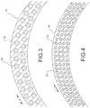
- the filaments 22 of the first facesheet 14 have a diameter ( d ) that is greater than a diameter ( d ) of the filaments 22 of the second facesheet 16 (see FIGs. 3-4 ).
- the diameter of the filaments 22 in the first facesheet 14 may be at least about two to about ten times greater than the diameter of the filaments 22 in the second facesheet 16, although it may extend beyond this range in some cases.
- the larger diameter filaments 22 in the first facesheet 14 may improve the resistance of these filaments to microbuckling and/or the resistance of these filaments to failure due to local peak stresses when the first facesheet 14 is subjected to compressive strain, thus increasing its compressive strength.
- the smaller diameter filaments 22 in the second facesheet 16 may improve its tensile strength.
- the chemical composition of the filaments 22 may be varied to adjust the respective compressive and tensile strengths of the first facesheet 14 and the second facesheet 16.
- alumina (Al 2 O 3 ) filaments may be used with varying percentages of silicates (or other molecules or elements) to tune the respective compressive and tensile strengths of the facesheets 14 and 16, although the chemical composition of the filaments 22 may be varied in numerous other ways as well.
- variation of the chemical composition of the filaments 22 in the facesheets 14 and 16 may also be used to tune the relative CTEs of the facesheets 14 and 16, such as to provide a slightly lower CTE in the first facesheet 14.
- the filaments 22 of the first facesheet 14 and the second facesheet 16 may have different interface strengths with the surrounding ceramic matrix 24.
- the interface strength between the filaments 22 and the ceramic matrix 24 of the first facesheet 14 may be higher than the interface strength between the filaments 22 and the ceramic matrix 24 of the second facesheet 16.
- the higher interface strength in the first facesheet 14 may increase its compressive properties relative to the second facesheet 16, while the weaker interface strength in the second facesheet 16 may increase its tensile properties relative to the first facesheet 14.
- Several strategies may be used to tune the interface strengths between the filaments 22 and the ceramic matrix 24 in the first facesheet 14 and the second facesheet 16.
- coatings on the filaments 22 and/or additives in the ceramic matrix 24 may be used to increase the chemical compatibility between the filaments 22 and the ceramic matrix 24 in the first facesheet 14, thereby increasing its compressive strength.
- a low density (or more porous) ceramic matrix 24, or incompatible coatings may be used in the second facesheet 16 to reduce the interface strength between the filaments 22 and the ceramic matrix 24.
- Strategies such as these for adjusting composite interface strengths, as well as other strategies, are well understood by those skilled in the art.
- such approaches may be used alone or in combination to tune the interface strengths of the facesheets 14 and 16, and their relative compressive and tensile strengths, as desired.
- the first facesheet 14 and the second facesheet 16 may also be varied in their relative degrees of orthotropy.
- the term "orthotropic" means that the properties of the facesheet vary in different directions in the plane of the facesheet
- the term "quasi-isotropic” means that the properties of the facesheet are the same in all directions in the plane of the facesheet.
- the first facesheet 14 may be made more highly orthotropic than the second facesheet 16, while the second facesheet 16 may be made quasi-isotropic.
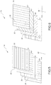
- the pre-preg layers 26 used to form the first facesheet 14 may have a more highly orthotropic layup (than the second facesheet 16) in which more of the filaments 22 are oriented in the 0° and/or 90° directions than in the other directions (e.g., 45°, -45°, 60°, - 60°, etc.) (see FIG. 5 ).
- the pre-preg layers 26 used to form the second facesheet 16 may have a quasi-isotropic layup in which equivalent amounts of the filaments 22 are oriented in each of the 0°, 45°, -45°, and 90° directions (see FIG. 6 ).
- first facesheet 14 may have both larger diameter filaments and a higher interface strength than the second facesheet 16.
- first facesheet 14 may have larger diameter filaments, a higher interface strength, and a more highly orthotropic layup than the second facesheet 16.
- the core 12 may have a honeycomb structure 28 ( FIG. 7 ), a foam structure 30 ( FIG. 8 ), or a truss structure 32 in which the core 12 includes diagonal members connecting the facesheets 14 and 16 ( FIG. 9 ), although many other types of core structures apparent to those skilled in the art may be used.
- the core 12 may have a CTE that matches or at least closely matches (i.e., within 0.9 x 10 -6 micrometer/meter/°C (0.5x10 -6 micrometer/meter/°F)) the CTEs of the first facesheet 14 and the second facesheet 16).
- the core 12 may be formed from a CMC having the same or similar chemical composition (i.e., the same filament and matrix composition) as the first facesheet 14 and the second facesheet 16.
- the core 12 may be formed from other high temperature capable materials having CTEs that match or at least closely match the CTEs of the first facesheet 14 and the second facesheet 16.
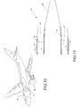
- FIGs. 10-11 A non-limiting application of the hybrid sandwich CMC 10 is shown in FIGs. 10-11 .
- the hybrid sandwich CMC 10 may be incorporated into an exhaust system 34 of an aircraft engine 36.
- the exhaust system 34 may include an exhaust nozzle 38 and a center body 40 radially inside of the exhaust nozzle 38 to define a flowpath 42 for exhaust gases therebetween.
- the hybrid sandwich CMC 10 may form at least a part of either or both of the exhaust nozzle 38 and the center body 40, with the first facesheet 14 tailored for high compressive strength facing the hot combustion gases of the flowpath 42, and the second facesheet 16 tailored for high tensile strength facing away from the flowpath 42, as shown.
- the hybrid sandwich CMC may be exposed to a high thermal gradient.
- the tailored compressive and tensile strengths of the first facesheet 14 and the second facesheet 16 may improve the ability of the hybrid sandwich CMC 10 to sustain stresses caused by the greater thermal expansion of the first facesheet 14 compared with non-hybrid sandwich CMCs of the prior art.
- the pre-preg layers 26 of the first facesheet 14 may be laid up in a stack to provide the first facesheet 14. If desired, an orthotropic layup may be established in the first facesheet 14, as described in detail above (see FIG. 5 ).
- the pre-preg layers 26 may be obtained as filament cloth pre-impregnated with a slurry precursor to the ceramic matrix 24, or they may be produced by dipping a filament cloth in the slurry precursor to the ceramic matrix 24.
- the first facesheet 14 may then be laid up on a cylindrical tool (or other suitable tool capable of creating a hybrid sandwich CMC 10 in a desired shape), according to a next block 54, as shown.
- the core 12 may then be laid up on the first facesheet 14, and the second facesheet 16 may be laid up on the core 12 to provide a layup stack on the tool according to the next blocks 56 and 58.
- the pre-preg layers 26 of the second facesheet 16 may be laid up to establish a quasi-isotropic arrangement as described above (see FIG. 6 ).
- the pre-preg layers 26 of the second facesheet 16 may be obtained as filament cloth pre-impregnated with a slurry precursor to the ceramic matrix 24, or they may be produced by dipping a filament cloth in the slurry precursor to the ceramic matrix 24
- the layup stack on the tool may then be compacted and cured at a first temperature to allow compounds in the ceramic matrix 24 to weakly bind the facesheets 14 and 16 and the core 12 together as a single structure that can be handled and may support its own weight.
- the block 60 may be carried out using techniques and equipment apparent to those skilled in the art such as heated presses, vacuum bagging, and autoclaving.
- the cured structure may then be removed from the tool, placed in a furnace, and sintered at a higher second temperature to more strongly bind the facesheets 14 and 16 and the core 12 together and provide the hybrid sandwich CMC 10 (block 62).
- the matching CTEs (or the at least closely matching CTEs) of the first facesheet 14, the second facesheet 16, and the core 12 may enable the hybrid sandwich CMC 10 to withstand cooling from the sintering temperatures, which may be on the order of several thousands of degrees Fahrenheit in some cases.
- the technology disclosed herein has industrial applicability in a variety of settings including, but not limited to, industrial applications using CMC sandwich components exposed to high thermal gradients.
- the technology disclosed herein provides a hybrid sandwich CMC in which the compressive and tensile strengths of the two opposing facesheets are tailored so that the hybrid sandwich CMC component is structurally robust enough to sustain a high thermal gradient.
- the facesheet exposed to the higher temperature environment is tailored for enhanced compressive properties
- the opposing facesheet exposed to a cooler environment is tailored for enhanced tensile properties.
- hybrid sandwich CMC may better sustain stresses caused by the greater thermal expansion of the higher temperature facesheet compared with sandwich CMCs of the prior art that use facesheets with the same compressive/tensile properties on both sides.
- This technology may be particularly useful for sandwich CMCs structures in which the two facesheets are rigidly tied together and constrained so that it cannot flex easily to reduce the stresses induced by thermal gradients, such as in some cylindrical structures.
- the hybrid sandwich CMC structures disclosed herein may provide improved aircraft exhaust system components compared with the metal-based structures used currently, as they are lighter in weight and are able to sustain longer exposures to exhaust temperatures. It is expected that the technology disclosed herein may find wide industrial applicability in a wide range of areas such as, but not limited to, aircraft exhaust system applications.
Landscapes
- Engineering & Computer Science (AREA)
- Chemical & Material Sciences (AREA)
- Ceramic Engineering (AREA)
- Mechanical Engineering (AREA)
- Materials Engineering (AREA)
- Structural Engineering (AREA)
- Organic Chemistry (AREA)
- Chemical Kinetics & Catalysis (AREA)
- Manufacturing & Machinery (AREA)
- Aviation & Aerospace Engineering (AREA)
- Laminated Bodies (AREA)
Description
- The present disclosure generally relates to ceramic matrix composites, and more specifically, relates to hybrid sandwich ceramic matrix composite structures that are exposed to thermal gradients.
- Ceramic matrix composites (CMCs) are composite materials consisting of a ceramic matrix having reinforcement materials (e.g., particulates, whiskers, non-woven fibers, woven fibers) embedded therein. CMCs are attractive materials for use in aerospace applications because they are relatively lightweight and are able to sustain high operating temperatures. For example, CMCs may be beneficial for the construction of exhaust system components because they are lighter in weight and are able to sustain longer exposures to exhaust temperatures than some metal-based structures (e.g., titanium and nickel-based alloys) used currently.
- CMC sandwich structures, which include a load-transferring core bonded to and between two identical facesheets, have been explored as exhaust components for aircraft applications (see
U.S. Patent Application Publication Number 2009/0004425 ). While effective, CMC sandwich components may be subjected to stresses when a high thermal gradient exists across the sandwich structure, particularly when the facesheets are constrained, such as in a cylindrical sandwich structure. Specifically, the facesheet that is exposed to a higher temperature environment (the 'hotter facesheet') expands or tries to expand, but is resisted by the opposing facesheet that is exposed a cooler environment (the 'cooler facesheet'). As a result, the hotter facesheet may be subjected to compression stress due to the expansion resistance of the cooler facesheet, while the cooler facesheet may be subjected to tension stress caused by the contraction resistance of the hotter facesheet. Under some extreme conditions, such competing forces may push the CMC sandwich component to its structural limits, and structural damage may occur. - Thus, there are challenges and limitations of existing art that are to be overcome. In particular, there is a need for more robust CMC sandwich structure designs with improved resilience under thermal gradient conditions.
-
US2009/0252907A1 relates to a hybrid ceramic structure with internal cooling arrangements. - The present invention provides a hybrid sandwich ceramic matrix composite (CMC) according to claim 1.
- In accordance with another aspect of the present disclosure, a method for fabricating a hybrid sandwich ceramic matrix composite (CMC) is disclosed according to claim 8.
- The features, functions, and advantages that have been discussed can be achieved independently in various embodiments or may be combined in yet other embodiments further details of which can be seen with reference to the following description and drawings.
-
-
FIG. 1 is a perspective view of a hybrid sandwich ceramic matrix composite (CMC), constructed in accordance with the present disclosure. -
FIG. 2 is a cross-sectional view through the section 2-2 ofFIG. 1 , constructed in accordance with the present disclosure. -
FIG. 3 is an expanded view of detail 3 ofFIG. 2 , illustrating a first facesheet of the hybrid sandwich CMC, constructed in accordance with one aspect of the present disclosure. -
FIG. 4 is an expanded view ofdetail 4 ofFIG. 2 , illustrating a second facesheet of the hybrid sandwich CMC, constructed in accordance with one aspect of the present disclosure. -
FIG. 5 is a perspective view, schematically illustrating an orthotropic layup of pre-preg filament layers to provide the first facesheet, in accordance with a method the present disclosure. -
FIG. 6 is a perspective view, schematically illustrating a quasi-isotropic layup of pre-preg filament layers to provide the second facesheet, in accordance with a method of the present disclosure. -
FIG. 7 is an expanded view ofdetail 7 ofFIG. 2 , illustrating a honeycomb core structure of the hybrid sandwich CMC, constructed in accordance with one aspect of the present disclosure. -
FIG. 8 is an expanded view similar toFIG. 7 , but showing a foam core structure, constructed in accordance with another aspect of the present disclosure. -
FIG. 9 is an expanded view similar toFIG. 7 , but showing a truss core structure, constructed in accordance with another aspect of the present disclosure. -
FIG. 10 is a perspective view of an aircraft having an exhaust system that may have components formed from the hybrid sandwich CMC of the present disclosure. -
FIG. 11 is a cross-sectional view through the section 11-11 ofFIG. 10 , depicting a center body and an exhaust nozzle formed from the hybrid sandwich CMC of the present disclosure. -
FIG. 12 is a flowchart depicting a series of steps that may be used to fabricate the hybrid sandwich CMC, in accordance with a method of the present disclosure. - It should be understood that the drawings are not necessarily drawn to scale and that the disclosed embodiments are sometimes illustrated schematically. It is to be further appreciated that the following detailed description is merely exemplary in nature and is not intended to limit the invention or the application and uses thereof. Hence, although the present disclosure is, for convenience of explanation, depicted and described as certain illustrative embodiments, it will be appreciated that it can be implemented in various other types of embodiments and in various other systems and environments.
- Referring now to the drawings, and with specific reference to
FIGs. 1-2 , a hybrid sandwich ceramic matrix composite (CMC) 10 is shown. As used herein, the term "CMC" refers to a material consisting of one or more reinforcing materials embedded in a ceramic matrix. In addition, the term "hybrid sandwich CMC" refers to a CMC material having a core between two CMC facesheets, wherein the two facesheets differ in at least one physical property. As a non-limiting example, thehybrid sandwich CMC 10 may be a component of an exhaust system of an aircraft engine, as will be described in further detail below. The hybrid sandwich CMC 10 may include acore 12 bonded to and between afirst facesheet 14 and asecond facesheet 16. Both of thefirst facesheet 14 and thesecond facesheet 16 may be formed from a CMC material. In one aspect of the present disclosure, thefirst facesheet 14, thesecond facesheet 16, and thecore 12 may each form a cylindrical structure such that the overall shape of thehybrid sandwich CMC 10 is cylindrical with anopen center 18, as shown. Alternatively, thehybrid sandwich CMC 10 may have another type of closed configuration, or may be otherwise constrained such that flexure of thefacesheets facesheets hybrid sandwich CMC 10 may have other three-dimensional shapes such as, but not limited to, cubical, spherical, or cone shapes. - Under some operating conditions, the
hybrid sandwich CMC 10 may be exposed to a high thermal gradient such that the first facesheet 14 (the "hotter" facesheet) is exposed to a higher temperature environment (e.g., hot exhaust gases) than the second facesheet 16 (the "cooler" facesheet). As used herein, a "high thermal gradient" refers to a condition in which the temperature difference between thefirst facesheet 14 and thesecond facesheet 16 is at least 93°C (200°F) or more. Furthermore, depending on its application, thehybrid sandwich CMC 10 may be acoustically treated to reduce or absorb sound. For example, the facesheet configured for exposure to the higher temperature environment (e.g., the first facesheet 14) may haveperforations 20 formed therethrough to allow sound to enter into and dampen inside of thecore 12. Although thefirst facesheet 14 is depicted as the inner facesheet inFIG. 2 , it is noted that in some applications the facesheet exposed to the higher temperature environment may be the outer facesheet. - Under high thermal gradient conditions, the
hotter facesheet 14 may try to expand more than thecooler facesheet 16 in the axial, radial, and circumferential directions. These expansion tendencies may cause the build-up of compressive stresses in the first (hotter)facesheet 14 and tensile stresses in the second (cooler)facesheet 16. In order to sustain the stresses on thehybrid sandwich CMC 10 under such conditions, the CMC material of thefirst facesheet 14 may be tailored such that thefirst facesheet 14 exhibits a higher compressive strength than its tensile strength. As a non-limiting possibility, the compressive strength of the first (hotter)facesheet 14 may exceed its tensile strength by about 1.5 times or more. Such tailoring may enable thefacesheet 14 to achieve a greater compressive strength than could be possible if the material was constructed with the aim of achieving nearly equivalent tensile and compressive strengths. Likewise, the CMC material of the second (cooler)facesheet 16 is constructed such that the second facesheet exhibits a greater tensile strength than its compressive strength. As a non-limiting possibility, the tensile strength of thesecond facesheet 16 may exceed its compressive strength by about 1.5 times or more. Such tailoring may enable a greater tensile strength to be achieved in thesecond facesheet 16 than could be possible if the material was constructed with the aim of achieving equivalent tensile and compressive strengths. As used herein, the term "compressive strength" refers to the ability of the facesheet to sustain forces when compressed primarily in the circumferential and axial directions, and the term "tensile strength" refers to the ability of the facesheet to sustain forces when pulled in expansion primarily in the circumferential and axial directions. These strengths may be for material in its pristine state or when the material has holes or damage present. As a non-limiting example, thefirst facesheet 14 may have a compressive strength greater than about 172 MPa (25 kilopounds per square inch (ksi)) and a tensile strength greater than about 34 MPa (5 ksi), while thesecond facesheet 16 may have a tensile strength greater than about 172 MPa (25 ksi) and a compressive strength of greater than about 34 MPa (5 ksi).
As a result of such a design, thehybrid sandwich CMC 10 may exhibit improved robustness and structural strength under high thermal gradient conditions compared to non-hybrid sandwich CMCs of the prior art that use two facesheets with nearly identical tensile and compressive strengths. - Turning now to
FIGs. 3-4 , the composition of thefirst facesheet 14 and thesecond facesheet 16 is shown in more detail. Thefirst facesheet 14 and thesecond facesheet 16 may each consist offilaments 22 embedded in aceramic matrix 24. Moreover, thefirst facesheet 14 and thesecond facesheet 16 may each be formed from one or more cured pre-preglayers 26 of thefilaments 22 pre-impregnated with the ceramic matrix 24 (seeFIGs. 5-6 and further details below). Thefilaments 22 may be continuous fibers having a fiber length to diameter ratio of 200 or more, and the continuous fibers may be in the form of unidirectional non-woven tape or woven fabrics. The continuous fibers may be ceramic fibers, although metallic fibers and/or carbon fibers coated with a non-oxidizable coating may also be used in some cases. However, thefilaments 22 may also be other types of reinforcing materials such as, but not limited to, short/discontinuous fibers, whiskers, or particulates. In addition, theceramic matrix 24 may include oxide ceramics such as alumina (Al2O3), magnesium oxide (MgO), and mulite (3Al2O3•2SiO2), and non-oxide ceramics such as silicon carbide (SiC), boron nitride (BN), and carbon (C), although many other types of ceramic matrices may also be used. - The
first facesheet 14 and thesecond facesheet 16 may both be formed from a CMC material having matching or at least closely matching coefficients of thermal expansion (CTEs) so that thehybrid sandwich CMC 10 is able to withstand high temperature sintering steps used during its fabrication. As used herein, "closely matching CTEs" refers to CTEs that are within about 0.9 x 10⁻⁶ micrometer/meter/°C (0.5x10⁻⁶ micrometer/meter/°F) of each other. In some cases, such small variations in the CTEs (on the order of 0.9 x 10⁻⁶ micrometer/meter/°C (0.5x10⁻⁶ micrometer/meter/°F)) may be acceptable and even beneficial. For example, if thefacesheet 14 exposed to higher temperatures during operation has a slightly lower CTE than thefacesheet 16, then cooling down from the sintering temperature during fabrication may create residual tensile stresses in thefirst facesheet 14 and residual compressive stresses infacesheet 16. These residual stresses may partially offset the opposite stresses induced during operation upon exposure to a thermal gradient, thereby enabling thehybrid CMC 10 to better sustain high thermal gradients in operation. - In order to provide matching or closely matching CTEs, the
first facesheet 14 and thesecond facesheet 16 may have the same or similar chemical compositions (i.e., the same filament composition and the same ceramic matrix composition) and may have the same or similar volume fraction of thefilaments 22 in thematrix 24. It is also noted that the facesheets 14 and 16 may differ in the chemical composition of thefilaments 22 and/or theceramic matrix 24 in some cases, provided that the CTEs of the two facesheets 14 and 16 are at least closely matching. As explained in further detail below, thefirst facesheet 14 and thesecond facesheet 16 may differ in at least one of a diameter of thefilaments 22, a chemistry of thefilaments 22, a degree of orthotropy, and an interface strength between thefilaments 22 and thematrix 24. It is these differences which may give rise to the higher compressive strength in thefirst facesheet 14 and the higher tensile strength in thesecond facesheet 16. In the present invention, thefilaments 22 of thefirst facesheet 14 have a diameter (d) that is greater than a diameter (d) of thefilaments 22 of the second facesheet 16 (seeFIGs. 3-4 ). For example, the diameter of thefilaments 22 in thefirst facesheet 14 may be at least about two to about ten times greater than the diameter of thefilaments 22 in thesecond facesheet 16, although it may extend beyond this range in some cases. In such an arrangement, thelarger diameter filaments 22 in thefirst facesheet 14 may improve the resistance of these filaments to microbuckling and/or the resistance of these filaments to failure due to local peak stresses when thefirst facesheet 14 is subjected to compressive strain, thus increasing its compressive strength. Moreover, since smaller diameter filaments may be manufactured with fewer structural defects, thesmaller diameter filaments 22 in thesecond facesheet 16 may improve its tensile strength. - Alternatively, the chemical composition of the
filaments 22 may be varied to adjust the respective compressive and tensile strengths of thefirst facesheet 14 and thesecond facesheet 16. For example, alumina (Al2O3) filaments may be used with varying percentages of silicates (or other molecules or elements) to tune the respective compressive and tensile strengths of thefacesheets filaments 22 may be varied in numerous other ways as well. It is also noted that such variation of the chemical composition of thefilaments 22 in thefacesheets facesheets first facesheet 14. - As another possibility, the
filaments 22 of thefirst facesheet 14 and thesecond facesheet 16 may have different interface strengths with the surroundingceramic matrix 24. Specifically, the interface strength between thefilaments 22 and theceramic matrix 24 of thefirst facesheet 14 may be higher than the interface strength between thefilaments 22 and theceramic matrix 24 of thesecond facesheet 16. The higher interface strength in thefirst facesheet 14 may increase its compressive properties relative to thesecond facesheet 16, while the weaker interface strength in thesecond facesheet 16 may increase its tensile properties relative to thefirst facesheet 14. - Several strategies may be used to tune the interface strengths between the
filaments 22 and theceramic matrix 24 in thefirst facesheet 14 and thesecond facesheet 16. For example, coatings on thefilaments 22 and/or additives in theceramic matrix 24 may be used to increase the chemical compatibility between thefilaments 22 and theceramic matrix 24 in thefirst facesheet 14, thereby increasing its compressive strength. Alternatively, a low density (or more porous)ceramic matrix 24, or incompatible coatings, may be used in thesecond facesheet 16 to reduce the interface strength between thefilaments 22 and theceramic matrix 24. Strategies such as these for adjusting composite interface strengths, as well as other strategies, are well understood by those skilled in the art. In addition, such approaches may be used alone or in combination to tune the interface strengths of thefacesheets - As yet another approach to tailor the respective compressive and tensile strengths of the
first facesheet 14 and thesecond facesheet 16, thefirst facesheet 14 and thesecond facesheet 16 may also be varied in their relative degrees of orthotropy. As used herein, the term "orthotropic" means that the properties of the facesheet vary in different directions in the plane of the facesheet, and the term "quasi-isotropic" means that the properties of the facesheet are the same in all directions in the plane of the facesheet. In particular, thefirst facesheet 14 may be made more highly orthotropic than thesecond facesheet 16, while thesecond facesheet 16 may be made quasi-isotropic. Specifically, thepre-preg layers 26 used to form thefirst facesheet 14 may have a more highly orthotropic layup (than the second facesheet 16) in which more of thefilaments 22 are oriented in the 0° and/or 90° directions than in the other directions (e.g., 45°, -45°, 60°, - 60°, etc.) (seeFIG. 5 ). Furthermore, thepre-preg layers 26 used to form thesecond facesheet 16 may have a quasi-isotropic layup in which equivalent amounts of thefilaments 22 are oriented in each of the 0°, 45°, -45°, and 90° directions (seeFIG. 6 ). Those skilled in the art will understand that alternative quasi-isotropic layups may have equivalent amounts of thefilaments 22 oriented in other directions as well, such as the 0°, 60°, and -60° directions. As a result of these layup arrangements, the more highly orthotropicfirst facesheet 14 may have improved compressive performance, while the quasi-isotropicsecond facesheet 16 may have improved tensile performance as the -45° and the 45° oriented filaments (and/or the -60° and the 60° oriented filaments, etc.) may provide viable load paths to transfer tensile load around holes, defects, or other damage. It is further noted that althoughFIGs. 4-5 depictpre-preg layers 26 with uni-directional filaments, similar layup concepts may be applied for pre-preg layers with woven filaments as well. - The concepts for tailoring the respective compressive and tensile strengths of the
facesheets first facesheet 14 may have both larger diameter filaments and a higher interface strength than thesecond facesheet 16. As another example, thefirst facesheet 14 may have larger diameter filaments, a higher interface strength, and a more highly orthotropic layup than thesecond facesheet 16. - Referring now to
FIGs. 7-9 , possible structures for the core 12 are shown. The core 12 may have a honeycomb structure 28 (FIG. 7 ), a foam structure 30 (FIG. 8 ), or atruss structure 32 in which thecore 12 includes diagonal members connecting thefacesheets 14 and 16 (FIG. 9 ), although many other types of core structures apparent to those skilled in the art may be used. The core 12 may have a CTE that matches or at least closely matches (i.e., within 0.9 x 10⁻⁶ micrometer/meter/°C (0.5x10⁻⁶ micrometer/meter/°F)) the CTEs of thefirst facesheet 14 and the second facesheet 16). In this regard, thecore 12 may be formed from a CMC having the same or similar chemical composition (i.e., the same filament and matrix composition) as thefirst facesheet 14 and thesecond facesheet 16. Alternatively, thecore 12 may be formed from other high temperature capable materials having CTEs that match or at least closely match the CTEs of thefirst facesheet 14 and thesecond facesheet 16. - A non-limiting application of the
hybrid sandwich CMC 10 is shown inFIGs. 10-11 . In particular, thehybrid sandwich CMC 10 may be incorporated into anexhaust system 34 of anaircraft engine 36. Theexhaust system 34 may include anexhaust nozzle 38 and acenter body 40 radially inside of theexhaust nozzle 38 to define aflowpath 42 for exhaust gases therebetween. Thehybrid sandwich CMC 10 may form at least a part of either or both of theexhaust nozzle 38 and thecenter body 40, with thefirst facesheet 14 tailored for high compressive strength facing the hot combustion gases of theflowpath 42, and thesecond facesheet 16 tailored for high tensile strength facing away from theflowpath 42, as shown. During periods of rapid temperature changes in theexhaust system 34, such as during the start of theengine 36 or during acceleration of theengine 36 from idle to full power, the hybrid sandwich CMC may be exposed to a high thermal gradient. The tailored compressive and tensile strengths of thefirst facesheet 14 and thesecond facesheet 16 may improve the ability of thehybrid sandwich CMC 10 to sustain stresses caused by the greater thermal expansion of thefirst facesheet 14 compared with non-hybrid sandwich CMCs of the prior art. - Turning now to
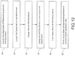
FIG. 12 , a method for fabricating thehybrid sandwich CMC 10 of the present disclosure is depicted. Beginning with theblock 50, thepre-preg layers 26 of thefirst facesheet 14 may be laid up in a stack to provide thefirst facesheet 14. If desired, an orthotropic layup may be established in thefirst facesheet 14, as described in detail above (seeFIG. 5 ). The pre-preg layers 26 may be obtained as filament cloth pre-impregnated with a slurry precursor to theceramic matrix 24, or they may be produced by dipping a filament cloth in the slurry precursor to theceramic matrix 24. - The
first facesheet 14 may then be laid up on a cylindrical tool (or other suitable tool capable of creating ahybrid sandwich CMC 10 in a desired shape), according to anext block 54, as shown. The core 12 may then be laid up on thefirst facesheet 14, and thesecond facesheet 16 may be laid up on the core 12 to provide a layup stack on the tool according to thenext blocks pre-preg layers 26 of thesecond facesheet 16 may be laid up to establish a quasi-isotropic arrangement as described above (seeFIG. 6 ). As with thefirst facesheet 14, thepre-preg layers 26 of thesecond facesheet 16 may be obtained as filament cloth pre-impregnated with a slurry precursor to theceramic matrix 24, or they may be produced by dipping a filament cloth in the slurry precursor to theceramic matrix 24 - According to a
next block 60, the layup stack on the tool may then be compacted and cured at a first temperature to allow compounds in theceramic matrix 24 to weakly bind thefacesheets block 60 may be carried out using techniques and equipment apparent to those skilled in the art such as heated presses, vacuum bagging, and autoclaving. The cured structure may then be removed from the tool, placed in a furnace, and sintered at a higher second temperature to more strongly bind thefacesheets first facesheet 14, thesecond facesheet 16, and the core 12 may enable thehybrid sandwich CMC 10 to withstand cooling from the sintering temperatures, which may be on the order of several thousands of degrees Fahrenheit in some cases. - Illustrative, non-exclusive examples of inventive subject matter according to Reference Examples are described in the the clauses A1-C20, below:
- A1. A hybrid sandwich ceramic matrix composite (CMC) 10, comprising:
- a
first facesheet 14 includingfilaments 22 in aceramic matrix 24; - a
second facesheet 16 includingfilaments 22 in aceramic matrix 24; and - a core 12 between and bonded to both of the first facesheet and the second facesheet, the hybrid sandwich CMC being configured for exposure to a thermal gradient in which the first facesheet is exposed to a higher temperature environment than the second facesheet, the first facesheet and the second facesheet having at least closely matching coefficients of thermal expansion, and the first facesheet having a higher compressive strength than the second facesheet.
- a
- A2. The
hybrid sandwich CMC 10 of clause 1, wherein thesecond facesheet 16 has a higher tensile strength than thefirst facesheet 14. - A3. The
hybrid sandwich CMC 10 of any ofclauses 1 and 2, wherein thefirst facesheet 14 has a compressive strength that is about 1.5 times higher than a tensile strength of the first facesheet, and wherein thesecond facesheet 16 has a tensile strength that is about 1.5 times higher than a compressive strength of the second facesheet. - A4. The
hybrid sandwich CMC 10 of any of clauses 1-3, wherein thefilaments 22 of thefirst facesheet 14 and thefilaments 22 of thesecond facesheet 16 have a same chemical composition, wherein theceramic matrix 24 of the first facesheet and the ceramic matrix of the second facesheet have a same chemical composition, and wherein a volume fraction of the filaments in the first facesheet is equal to a volume fraction of the filaments in the second facesheet. - A5. The
hybrid sandwich CMC 10 of any of clauses 1-4, wherein the hybrid sandwich CMC is cylindrical. - A6. The
hybrid sandwich CMC 10 of any of clauses 1-5, wherein a diameter of thefilaments 22 in thefirst facesheet 14 is greater than a diameter of the filaments in thesecond facesheet 16. - A7. The
hybrid sandwich CMC 10 of any of clauses 1-6, wherein thefirst facesheet 14 is more highly orthotropic than thesecond facesheet 16. - A8. The
hybrid sandwich CMC 10 of any of clauses 1-7, wherein an interface strength between thefilaments 22 and theceramic matrix 24 of thefirst facesheet 14 is stronger than an interface strength between thefilaments 22 and theceramic matrix 24 of thesecond facesheet 16. - A9. The
hybrid sandwich CMC 10 of any of clauses 1-8, wherein a coefficient of thermal expansion of thefirst facesheet 14 is lower than a coefficient of thermal expansion of thesecond facesheet 16. - A10. The
hybrid sandwich CMC 10 of any of clauses 1-9, wherein the hybrid sandwich CMC is part of a component of anaircraft exhaust system 34, and wherein thefirst facesheet 14 faces anexhaust gas flowpath 42 of the aircraft exhaust system. - B11. A hybrid sandwich ceramic matrix composite (CMC) 10, comprising:
- a
first facesheet 14 includingfilaments 22 in aceramic matrix 24; - a
second facesheet 16 includingfilaments 22 in aceramic matrix 24; and - a core 12 between and bonded to both of the first facesheet and the second facesheet, the first facesheet and the second facesheet having at least closely matching coefficients of thermal expansion but differing in at least one of a diameter of the filaments, a chemistry of the filaments, a degree of orthotropy, and an interface strength between the filaments and the ceramic matrix.
- a
- B12. The
hybrid sandwich CMC 10 ofclause 11, wherein the hybrid sandwich CMC is configured for exposure to a thermal gradient in which thefirst facesheet 14 is exposed to a higher temperature environment than thesecond facesheet 16. - B13. The
hybrid sandwich CMC 10 of any of clauses 11-12, wherein thefirst facesheet 14 has a higher compressive strength than thesecond facesheet 16. - B14. The
hybrid sandwich CMC 10 of any of clauses 11-13, wherein thesecond facesheet 16 has a higher tensile strength than thefirst facesheet 14. - B15. The
hybrid sandwich CMC 10 of any of clauses 11-14, wherein a diameter of thefilaments 22 of thefirst facesheet 14 is greater than a diameter of thefilaments 22 of thesecond facesheet 16. - B16. The
hybrid sandwich CMC 10 of any of clauses 11-15, wherein thefirst facesheet 14 is more highly orthotropic than thesecond facesheet 16. - B17. The
hybrid sandwich CMC 10 of any of clauses 11-16, wherein an interface strength between thefilaments 22 and theceramic matrix 24 of thefirst facesheet 14 is stronger than an interface strength between thefilaments 22 and theceramic matrix 24 of thesecond facesheet 16. - B18. The
hybrid sandwich CMC 10 of any of clauses 11-17, wherein a coefficient of thermal expansion of thefirst facesheet 14 is lower than a coefficient of thermal expansion of thesecond facesheet 16. - B19. The
hybrid sandwich CMC 10 of any of clauses 11-18, wherein the hybrid sandwich CMC is cylindrical. - C20. A method for fabricating a hybrid sandwich ceramic matrix composite (CMC) 10, comprising:
- laying up 54 a
first facesheet 14 on a tool, the first facesheet including pre-preg layers offilaments 22 in aceramic matrix 24; - laying up 56 a
core 12 on the first facesheet; - laying up 58 a
second facesheet 16 on the core to provide a layup stack, the second facesheet including pre-preg layers offilaments 22 in aceramic matrix 24, the first facesheet and the second facesheet differing in at least one of a diameter of the filaments, a chemistry of the filaments, a degree of orthotropy, and an interface strength between the filaments and the ceramic matrix; - curing 60 the layup stack at a first temperature; and
- sintering 62 the layup stack at a second temperature to provide the hybrid sandwich CMC.
- laying up 54 a
- In general, it can therefore be seen that the technology disclosed herein has industrial applicability in a variety of settings including, but not limited to, industrial applications using CMC sandwich components exposed to high thermal gradients. The technology disclosed herein provides a hybrid sandwich CMC in which the compressive and tensile strengths of the two opposing facesheets are tailored so that the hybrid sandwich CMC component is structurally robust enough to sustain a high thermal gradient. Specifically, the facesheet exposed to the higher temperature environment is tailored for enhanced compressive properties, while the opposing facesheet exposed to a cooler environment is tailored for enhanced tensile properties. These properties allow hybrid sandwich CMC to better sustain stresses caused by the greater thermal expansion of the higher temperature facesheet compared with sandwich CMCs of the prior art that use facesheets with the same compressive/tensile properties on both sides. This technology may be particularly useful for sandwich CMCs structures in which the two facesheets are rigidly tied together and constrained so that it cannot flex easily to reduce the stresses induced by thermal gradients, such as in some cylindrical structures. Moreover, the hybrid sandwich CMC structures disclosed herein may provide improved aircraft exhaust system components compared with the metal-based structures used currently, as they are lighter in weight and are able to sustain longer exposures to exhaust temperatures. It is expected that the technology disclosed herein may find wide industrial applicability in a wide range of areas such as, but not limited to, aircraft exhaust system applications.
Claims (8)
- A hybrid sandwich ceramic matrix composite (CMC) (10), comprising:a first facesheet (14) including filaments (22) in a ceramic matrix (24);a second facesheet (16) including filaments (22) in a ceramic matrix (24); anda core (12) between and bonded to both of the first facesheet and the second facesheet, the hybrid sandwich CMC being configured for exposure to a thermal gradient in which the first facesheet is exposed to a higher temperature environment than the second facesheet, the first facesheet and the second facesheet having at least closely matching coefficients of thermal expansion, the coefficients of thermal expansion being within 0.9 x 10⁻⁶ micrometer/meter/°C (0.5 x 10⁻⁶ micrometer/meter/°F) of each other, the second facesheet (16) having a higher tensile strength than the first facesheet (14), and the first facesheet having a higher compressive strength than the second facesheet,characterised in that a diameter of the filaments (22) in the first facesheet (14) is greater than a diameter of the filaments in the second facesheet (16).
- The hybrid sandwich CMC (10) of any of claim 1, wherein the first facesheet 14) has a compressive strength that is 1.5 times higher than a tensile strength of the first facesheet, and wherein the second facesheet (16) has a tensile strength that is 1.5 times higher than a compressive strength of the second facesheet.
- The hybrid sandwich CMC (10) ofclaim 1 or claim 2, wherein the filaments (22) of the first facesheet (14) and the filaments (22) of the second facesheet (16) have a same chemical composition, wherein the ceramic matrix (24) of the first facesheet and the ceramic matrix of the second facesheet have a same chemical composition, and wherein a volume fraction of the filaments in the first facesheet is equal to a volume fraction of the filaments in the second facesheet.
- The hybrid sandwich CMC (10) of any of claims 1-3, wherein the hybrid sandwich CMC is cylindrical.
- The hybrid sandwich CMC (10) of any of claims 1-4, wherein the first facesheet (14) is more highly orthotropic than the second facesheet (16).
- The hybrid sandwich CMC (10) of any of claims 1-5, wherein an interface strength between the filaments (22) and the ceramic matrix (24) of the first facesheet (14) is stronger than an interface strength between the filaments (22) and the ceramic matrix (24) of the second facesheet (16).
- The hybrid sandwich CMC (10) of any of claims 1-6, wherein the hybrid sandwich CMC is part of a component of an aircraft exhaust system (34), and wherein the first facesheet (14) faces an exhaust gas flowpath (42)of the aircraft exhaust system.
- A method for fabricating the hybrid sandwich ceramic matrix composite (CMC) (10) according to claim 1, comprising:laying up (54) a first facesheet (14) on a tool, the first facesheet including pre-preg layers of filaments (22) in a ceramic matrix (24);laying up (56) a core (12) on the first facesheet;laying up (58) a second facesheet (16) on the core to provide a layup stack, the second facesheet including pre-preg layers of filaments (22) in a ceramic matrix (24), the first facesheet and the second facesheet differing in at least one of a diameter of the filaments, a chemistry of the filaments, a degree of orthotropy, and an interface strength between the filaments and the ceramic matrix;curing (60) the layup stack at a first temperature; andsintering (62) the layup stack at a second temperature to provide the hybrid sandwich CMC.
Applications Claiming Priority (1)
| Application Number | Priority Date | Filing Date | Title |
|---|---|---|---|
| US14/593,682 US9850173B2 (en) | 2015-01-09 | 2015-01-09 | Hybrid sandwich ceramic matrix composite |
Publications (2)
| Publication Number | Publication Date |
|---|---|
| EP3042763A1 EP3042763A1 (en) | 2016-07-13 |
| EP3042763B1 true EP3042763B1 (en) | 2018-01-10 |
Family
ID=54770832
Family Applications (1)
| Application Number | Title | Priority Date | Filing Date |
|---|---|---|---|
| EP15196462.4A Active EP3042763B1 (en) | 2015-01-09 | 2015-11-26 | Hybrid sandwich ceramic matrix composite |
Country Status (7)
| Country | Link |
|---|---|
| US (1) | US9850173B2 (en) |
| EP (1) | EP3042763B1 (en) |
| JP (1) | JP6719210B2 (en) |
| KR (1) | KR102380711B1 (en) |
| CN (1) | CN105774094B (en) |
| ES (1) | ES2665244T3 (en) |
| RU (1) | RU2698695C2 (en) |
Families Citing this family (2)
| Publication number | Priority date | Publication date | Assignee | Title |
|---|---|---|---|---|
| US9896954B2 (en) * | 2014-10-14 | 2018-02-20 | Rolls-Royce Corporation | Dual-walled ceramic matrix composite (CMC) component with integral cooling and method of making a CMC component with integral cooling |
| CN110092645B (en) * | 2019-05-24 | 2021-07-13 | 广东工业大学 | Composite ceramic substrate and preparation method thereof |
Citations (1)
| Publication number | Priority date | Publication date | Assignee | Title |
|---|---|---|---|---|
| EP2386739A1 (en) * | 2010-05-11 | 2011-11-16 | Ibiden Co., Ltd. | Mat, method for producing the mat, and exhaust gas purifying apparatus with the mat |
Family Cites Families (14)
| Publication number | Priority date | Publication date | Assignee | Title |
|---|---|---|---|---|
| US5376598A (en) | 1987-10-08 | 1994-12-27 | The Boeing Company | Fiber reinforced ceramic matrix laminate |
| US5223064A (en) * | 1989-10-26 | 1993-06-29 | Corning Incorporated | Method of making laminated hybrid ceramic matrix composites |
| US5153152A (en) * | 1991-10-04 | 1992-10-06 | Corning Incorporated | Multicomponent ceramic matrix composites |
| US6025048A (en) * | 1995-06-29 | 2000-02-15 | The Regents Of The University Of California | Hybrid ceramic matrix composite laminates |
| US6251815B1 (en) * | 2000-01-18 | 2001-06-26 | The United States Of America As Represented By The Secretary Of The Air Force | Thermal gradient resistant ceramic composite |
| FR2882356B1 (en) * | 2005-02-23 | 2008-08-15 | Snecma Propulsion Solide Sa | METHOD FOR MANUFACTURING PIECE OF COMPOSITE MATERIAL WITH CERAMIC MATRIX AND PART THUS OBTAINED |
| US7708851B2 (en) * | 2005-10-25 | 2010-05-04 | General Electric Company | Process of producing a ceramic matrix composite article and article formed thereby |
| US8869673B2 (en) * | 2006-01-31 | 2014-10-28 | Sikorsky Aircraft Corporation | Structural panel with ballistic protection |
| US20090004425A1 (en) | 2007-06-28 | 2009-01-01 | The Boeing Company | Ceramic Matrix Composite Structure having Fluted Core and Method for Making the Same |
| US8715439B2 (en) | 2008-03-07 | 2014-05-06 | The Boeing Company | Method for making hybrid metal-ceramic matrix composite structures and structures made thereby |
| US8202588B2 (en) | 2008-04-08 | 2012-06-19 | Siemens Energy, Inc. | Hybrid ceramic structure with internal cooling arrangements |
| US20100233424A1 (en) | 2009-03-10 | 2010-09-16 | The Boeing Company | Composite structures employing quasi-isotropic laminates |
| WO2012118516A1 (en) | 2010-05-17 | 2012-09-07 | General Electronic Company | Ceramic matrix composite structures, components formed therewith, and methods of producing |
| US9726025B2 (en) * | 2013-03-15 | 2017-08-08 | Rolls-Royce Corporation | Ceramic matrix composite |
-
2015
- 2015-01-09 US US14/593,682 patent/US9850173B2/en active Active
- 2015-09-22 RU RU2015140275A patent/RU2698695C2/en active
- 2015-11-26 EP EP15196462.4A patent/EP3042763B1/en active Active
- 2015-11-26 ES ES15196462.4T patent/ES2665244T3/en active Active
- 2015-12-30 CN CN201511016856.9A patent/CN105774094B/en active Active
-
2016
- 2016-01-07 JP JP2016001541A patent/JP6719210B2/en active Active
- 2016-01-07 KR KR1020160002157A patent/KR102380711B1/en active IP Right Grant
Patent Citations (1)
| Publication number | Priority date | Publication date | Assignee | Title |
|---|---|---|---|---|
| EP2386739A1 (en) * | 2010-05-11 | 2011-11-16 | Ibiden Co., Ltd. | Mat, method for producing the mat, and exhaust gas purifying apparatus with the mat |
Also Published As
| Publication number | Publication date |
|---|---|
| ES2665244T3 (en) | 2018-04-25 |
| KR20160086428A (en) | 2016-07-19 |
| JP2016196181A (en) | 2016-11-24 |
| CN105774094B (en) | 2019-12-13 |
| RU2015140275A3 (en) | 2019-03-06 |
| US20160264476A1 (en) | 2016-09-15 |
| RU2698695C2 (en) | 2019-08-28 |
| CN105774094A (en) | 2016-07-20 |
| EP3042763A1 (en) | 2016-07-13 |
| KR102380711B1 (en) | 2022-03-29 |
| JP6719210B2 (en) | 2020-07-08 |
| US9850173B2 (en) | 2017-12-26 |
| RU2015140275A (en) | 2017-03-30 |
Similar Documents
| Publication | Publication Date | Title |
|---|---|---|
| US9261008B2 (en) | Exhaust with an acoustic attenuation system | |
| US10954168B2 (en) | Ceramic matrix composite articles and methods for forming same | |
| US10066581B2 (en) | Structure for fastening after-body parts of an aeroengine | |
| JPH0365571A (en) | Compacted member and its manufacture method and preform | |
| US10612186B2 (en) | Method for producing a curved honeycomb structure made from composite material | |
| JP2013543072A (en) | Ceramic matrix composite structure, components formed using the same, and manufacturing method | |
| Ortona et al. | An integrated assembly method of sandwich structured ceramic matrix composites | |
| Luo et al. | High-performance 3D SiC/PyC/SiC composites fabricated by an optimized PIP process with a new precursor and a thermal molding method | |
| WO2014137478A1 (en) | Methods for reducing the process-induced shrinkage in a laminated ceramic matrix composite, and articles made therefrom | |
| EP3042763B1 (en) | Hybrid sandwich ceramic matrix composite | |
| JP2018155477A (en) | Rigidized hybrid insulating non-oxide thermal protection system and method of producing non-oxide ceramic composite for making the same | |
| Fitriani et al. | Fabrication of tubular SiCf/SiC using different preform architectures by electrophoretic deposition and hot pressing | |
| US6935594B1 (en) | Composite components with integral protective casings | |
| CN108137418B (en) | Composite material part | |
| CA2920513A1 (en) | Ceramic matrix composite articles and methods for forming same | |
| US20230382810A1 (en) | Composites and methods of forming composites having an increased volume of oxidation resistant ceramic particles | |
| Goodman | HoneySiC: a new optomechanical material for low-areal cost and density | |
| Alberto Ortona et al. | SILICON CARBIDE BASED SANDWICH STRUCTURES: PROCESSING AND PROPERTIES |
Legal Events
| Date | Code | Title | Description |
|---|---|---|---|
| PUAI | Public reference made under article 153(3) epc to a published international application that has entered the european phase |
Free format text: ORIGINAL CODE: 0009012 |
|
| 17P | Request for examination filed |
Effective date: 20151126 |
|
| AK | Designated contracting states |
Kind code of ref document: A1 Designated state(s): AL AT BE BG CH CY CZ DE DK EE ES FI FR GB GR HR HU IE IS IT LI LT LU LV MC MK MT NL NO PL PT RO RS SE SI SK SM TR |
|
| AX | Request for extension of the european patent |
Extension state: BA ME |
|
| 17Q | First examination report despatched |
Effective date: 20170403 |
|
| GRAP | Despatch of communication of intention to grant a patent |
Free format text: ORIGINAL CODE: EPIDOSNIGR1 |
|
| INTG | Intention to grant announced |
Effective date: 20170619 |
|
| GRAS | Grant fee paid |
Free format text: ORIGINAL CODE: EPIDOSNIGR3 |
|
| GRAA | (expected) grant |
Free format text: ORIGINAL CODE: 0009210 |
|
| AK | Designated contracting states |
Kind code of ref document: B1 Designated state(s): AL AT BE BG CH CY CZ DE DK EE ES FI FR GB GR HR HU IE IS IT LI LT LU LV MC MK MT NL NO PL PT RO RS SE SI SK SM TR |
|
| REG | Reference to a national code |
Ref country code: CH Ref legal event code: EP Ref country code: AT Ref legal event code: REF Ref document number: 961921 Country of ref document: AT Kind code of ref document: T Effective date: 20180115 |
|
| REG | Reference to a national code |
Ref country code: IE Ref legal event code: FG4D |
|
| REG | Reference to a national code |
Ref country code: DE Ref legal event code: R096 Ref document number: 602015007334 Country of ref document: DE |
|
| REG | Reference to a national code |
Ref country code: ES Ref legal event code: FG2A Ref document number: 2665244 Country of ref document: ES Kind code of ref document: T3 Effective date: 20180425 |
|
| REG | Reference to a national code |
Ref country code: NL Ref legal event code: MP Effective date: 20180110 |
|
| REG | Reference to a national code |
Ref country code: AT Ref legal event code: MK05 Ref document number: 961921 Country of ref document: AT Kind code of ref document: T Effective date: 20180110 |
|
| PG25 | Lapsed in a contracting state [announced via postgrant information from national office to epo] |
Ref country code: NL Free format text: LAPSE BECAUSE OF FAILURE TO SUBMIT A TRANSLATION OF THE DESCRIPTION OR TO PAY THE FEE WITHIN THE PRESCRIBED TIME-LIMIT Effective date: 20180110 |
|
| PG25 | Lapsed in a contracting state [announced via postgrant information from national office to epo] |
Ref country code: CY Free format text: LAPSE BECAUSE OF FAILURE TO SUBMIT A TRANSLATION OF THE DESCRIPTION OR TO PAY THE FEE WITHIN THE PRESCRIBED TIME-LIMIT Effective date: 20180110 Ref country code: LT Free format text: LAPSE BECAUSE OF FAILURE TO SUBMIT A TRANSLATION OF THE DESCRIPTION OR TO PAY THE FEE WITHIN THE PRESCRIBED TIME-LIMIT Effective date: 20180110 Ref country code: HR Free format text: LAPSE BECAUSE OF FAILURE TO SUBMIT A TRANSLATION OF THE DESCRIPTION OR TO PAY THE FEE WITHIN THE PRESCRIBED TIME-LIMIT Effective date: 20180110 Ref country code: FI Free format text: LAPSE BECAUSE OF FAILURE TO SUBMIT A TRANSLATION OF THE DESCRIPTION OR TO PAY THE FEE WITHIN THE PRESCRIBED TIME-LIMIT Effective date: 20180110 Ref country code: NO Free format text: LAPSE BECAUSE OF FAILURE TO SUBMIT A TRANSLATION OF THE DESCRIPTION OR TO PAY THE FEE WITHIN THE PRESCRIBED TIME-LIMIT Effective date: 20180410 |
|
| PG25 | Lapsed in a contracting state [announced via postgrant information from national office to epo] |
Ref country code: PL Free format text: LAPSE BECAUSE OF FAILURE TO SUBMIT A TRANSLATION OF THE DESCRIPTION OR TO PAY THE FEE WITHIN THE PRESCRIBED TIME-LIMIT Effective date: 20180110 Ref country code: RS Free format text: LAPSE BECAUSE OF FAILURE TO SUBMIT A TRANSLATION OF THE DESCRIPTION OR TO PAY THE FEE WITHIN THE PRESCRIBED TIME-LIMIT Effective date: 20180110 Ref country code: AT Free format text: LAPSE BECAUSE OF FAILURE TO SUBMIT A TRANSLATION OF THE DESCRIPTION OR TO PAY THE FEE WITHIN THE PRESCRIBED TIME-LIMIT Effective date: 20180110 Ref country code: BG Free format text: LAPSE BECAUSE OF FAILURE TO SUBMIT A TRANSLATION OF THE DESCRIPTION OR TO PAY THE FEE WITHIN THE PRESCRIBED TIME-LIMIT Effective date: 20180410 Ref country code: GR Free format text: LAPSE BECAUSE OF FAILURE TO SUBMIT A TRANSLATION OF THE DESCRIPTION OR TO PAY THE FEE WITHIN THE PRESCRIBED TIME-LIMIT Effective date: 20180411 Ref country code: IS Free format text: LAPSE BECAUSE OF FAILURE TO SUBMIT A TRANSLATION OF THE DESCRIPTION OR TO PAY THE FEE WITHIN THE PRESCRIBED TIME-LIMIT Effective date: 20180510 Ref country code: SE Free format text: LAPSE BECAUSE OF FAILURE TO SUBMIT A TRANSLATION OF THE DESCRIPTION OR TO PAY THE FEE WITHIN THE PRESCRIBED TIME-LIMIT Effective date: 20180110 Ref country code: LV Free format text: LAPSE BECAUSE OF FAILURE TO SUBMIT A TRANSLATION OF THE DESCRIPTION OR TO PAY THE FEE WITHIN THE PRESCRIBED TIME-LIMIT Effective date: 20180110 |
|
| REG | Reference to a national code |
Ref country code: DE Ref legal event code: R097 Ref document number: 602015007334 Country of ref document: DE |
|
| PG25 | Lapsed in a contracting state [announced via postgrant information from national office to epo] |
Ref country code: AL Free format text: LAPSE BECAUSE OF FAILURE TO SUBMIT A TRANSLATION OF THE DESCRIPTION OR TO PAY THE FEE WITHIN THE PRESCRIBED TIME-LIMIT Effective date: 20180110 Ref country code: EE Free format text: LAPSE BECAUSE OF FAILURE TO SUBMIT A TRANSLATION OF THE DESCRIPTION OR TO PAY THE FEE WITHIN THE PRESCRIBED TIME-LIMIT Effective date: 20180110 Ref country code: IT Free format text: LAPSE BECAUSE OF FAILURE TO SUBMIT A TRANSLATION OF THE DESCRIPTION OR TO PAY THE FEE WITHIN THE PRESCRIBED TIME-LIMIT Effective date: 20180110 Ref country code: RO Free format text: LAPSE BECAUSE OF FAILURE TO SUBMIT A TRANSLATION OF THE DESCRIPTION OR TO PAY THE FEE WITHIN THE PRESCRIBED TIME-LIMIT Effective date: 20180110 |
|
| PLBE | No opposition filed within time limit |
Free format text: ORIGINAL CODE: 0009261 |
|
| STAA | Information on the status of an ep patent application or granted ep patent |
Free format text: STATUS: NO OPPOSITION FILED WITHIN TIME LIMIT |
|
| PG25 | Lapsed in a contracting state [announced via postgrant information from national office to epo] |
Ref country code: SK Free format text: LAPSE BECAUSE OF FAILURE TO SUBMIT A TRANSLATION OF THE DESCRIPTION OR TO PAY THE FEE WITHIN THE PRESCRIBED TIME-LIMIT Effective date: 20180110 Ref country code: CZ Free format text: LAPSE BECAUSE OF FAILURE TO SUBMIT A TRANSLATION OF THE DESCRIPTION OR TO PAY THE FEE WITHIN THE PRESCRIBED TIME-LIMIT Effective date: 20180110 Ref country code: DK Free format text: LAPSE BECAUSE OF FAILURE TO SUBMIT A TRANSLATION OF THE DESCRIPTION OR TO PAY THE FEE WITHIN THE PRESCRIBED TIME-LIMIT Effective date: 20180110 Ref country code: SM Free format text: LAPSE BECAUSE OF FAILURE TO SUBMIT A TRANSLATION OF THE DESCRIPTION OR TO PAY THE FEE WITHIN THE PRESCRIBED TIME-LIMIT Effective date: 20180110 |
|
| 26N | No opposition filed |
Effective date: 20181011 |
|
| PG25 | Lapsed in a contracting state [announced via postgrant information from national office to epo] |
Ref country code: SI Free format text: LAPSE BECAUSE OF FAILURE TO SUBMIT A TRANSLATION OF THE DESCRIPTION OR TO PAY THE FEE WITHIN THE PRESCRIBED TIME-LIMIT Effective date: 20180110 |
|
| REG | Reference to a national code |
Ref country code: CH Ref legal event code: PL |
|
| PG25 | Lapsed in a contracting state [announced via postgrant information from national office to epo] |
Ref country code: LU Free format text: LAPSE BECAUSE OF NON-PAYMENT OF DUE FEES Effective date: 20181126 Ref country code: MC Free format text: LAPSE BECAUSE OF FAILURE TO SUBMIT A TRANSLATION OF THE DESCRIPTION OR TO PAY THE FEE WITHIN THE PRESCRIBED TIME-LIMIT Effective date: 20180110 |
|
| REG | Reference to a national code |
Ref country code: BE Ref legal event code: MM Effective date: 20181130 |
|
| REG | Reference to a national code |
Ref country code: IE Ref legal event code: MM4A |
|
| PG25 | Lapsed in a contracting state [announced via postgrant information from national office to epo] |
Ref country code: LI Free format text: LAPSE BECAUSE OF NON-PAYMENT OF DUE FEES Effective date: 20181130 Ref country code: CH Free format text: LAPSE BECAUSE OF NON-PAYMENT OF DUE FEES Effective date: 20181130 |
|
| PG25 | Lapsed in a contracting state [announced via postgrant information from national office to epo] |
Ref country code: IE Free format text: LAPSE BECAUSE OF NON-PAYMENT OF DUE FEES Effective date: 20181126 |
|
| PG25 | Lapsed in a contracting state [announced via postgrant information from national office to epo] |
Ref country code: BE Free format text: LAPSE BECAUSE OF NON-PAYMENT OF DUE FEES Effective date: 20181130 |
|
| REG | Reference to a national code |
Ref country code: DE Ref legal event code: R082 Ref document number: 602015007334 Country of ref document: DE Representative=s name: MAIER, LL.M., MICHAEL C., DE Ref country code: DE Ref legal event code: R082 Ref document number: 602015007334 Country of ref document: DE Representative=s name: BOULT WADE TENNANT LLP, DE |
|
| PG25 | Lapsed in a contracting state [announced via postgrant information from national office to epo] |
Ref country code: MT Free format text: LAPSE BECAUSE OF NON-PAYMENT OF DUE FEES Effective date: 20181126 |
|
| REG | Reference to a national code |
Ref country code: DE Ref legal event code: R082 Ref document number: 602015007334 Country of ref document: DE Representative=s name: BOULT WADE TENNANT LLP, DE |
|
| PG25 | Lapsed in a contracting state [announced via postgrant information from national office to epo] |
Ref country code: TR Free format text: LAPSE BECAUSE OF FAILURE TO SUBMIT A TRANSLATION OF THE DESCRIPTION OR TO PAY THE FEE WITHIN THE PRESCRIBED TIME-LIMIT Effective date: 20180110 |
|
| PG25 | Lapsed in a contracting state [announced via postgrant information from national office to epo] |
Ref country code: PT Free format text: LAPSE BECAUSE OF FAILURE TO SUBMIT A TRANSLATION OF THE DESCRIPTION OR TO PAY THE FEE WITHIN THE PRESCRIBED TIME-LIMIT Effective date: 20180110 |
|
| PG25 | Lapsed in a contracting state [announced via postgrant information from national office to epo] |
Ref country code: HU Free format text: LAPSE BECAUSE OF FAILURE TO SUBMIT A TRANSLATION OF THE DESCRIPTION OR TO PAY THE FEE WITHIN THE PRESCRIBED TIME-LIMIT; INVALID AB INITIO Effective date: 20151126 Ref country code: MK Free format text: LAPSE BECAUSE OF NON-PAYMENT OF DUE FEES Effective date: 20180110 |
|
| P01 | Opt-out of the competence of the unified patent court (upc) registered |
Effective date: 20230516 |
|
| PGFP | Annual fee paid to national office [announced via postgrant information from national office to epo] |
Ref country code: GB Payment date: 20231127 Year of fee payment: 9 |
|
| PGFP | Annual fee paid to national office [announced via postgrant information from national office to epo] |
Ref country code: ES Payment date: 20231201 Year of fee payment: 9 |
|
| PGFP | Annual fee paid to national office [announced via postgrant information from national office to epo] |
Ref country code: FR Payment date: 20231127 Year of fee payment: 9 Ref country code: DE Payment date: 20231129 Year of fee payment: 9 |