EP3041233A1 - High frame rate-low frame rate transmission technique - Google Patents
High frame rate-low frame rate transmission technique Download PDFInfo
- Publication number
- EP3041233A1 EP3041233A1 EP14307218.9A EP14307218A EP3041233A1 EP 3041233 A1 EP3041233 A1 EP 3041233A1 EP 14307218 A EP14307218 A EP 14307218A EP 3041233 A1 EP3041233 A1 EP 3041233A1
- Authority
- EP
- European Patent Office
- Prior art keywords
- video content
- encoding mode
- lfr
- mode designation
- content segment
- Prior art date
- Legal status (The legal status is an assumption and is not a legal conclusion. Google has not performed a legal analysis and makes no representation as to the accuracy of the status listed.)
- Withdrawn
Links
Images


Classifications
-
- H—ELECTRICITY
- H04—ELECTRIC COMMUNICATION TECHNIQUE
- H04N—PICTORIAL COMMUNICATION, e.g. TELEVISION
- H04N21/00—Selective content distribution, e.g. interactive television or video on demand [VOD]
-
- H—ELECTRICITY
- H04—ELECTRIC COMMUNICATION TECHNIQUE
- H04N—PICTORIAL COMMUNICATION, e.g. TELEVISION
- H04N19/00—Methods or arrangements for coding, decoding, compressing or decompressing digital video signals
- H04N19/10—Methods or arrangements for coding, decoding, compressing or decompressing digital video signals using adaptive coding
- H04N19/102—Methods or arrangements for coding, decoding, compressing or decompressing digital video signals using adaptive coding characterised by the element, parameter or selection affected or controlled by the adaptive coding
- H04N19/115—Selection of the code volume for a coding unit prior to coding
-
- H—ELECTRICITY
- H04—ELECTRIC COMMUNICATION TECHNIQUE
- H04N—PICTORIAL COMMUNICATION, e.g. TELEVISION
- H04N19/00—Methods or arrangements for coding, decoding, compressing or decompressing digital video signals
- H04N19/10—Methods or arrangements for coding, decoding, compressing or decompressing digital video signals using adaptive coding
- H04N19/102—Methods or arrangements for coding, decoding, compressing or decompressing digital video signals using adaptive coding characterised by the element, parameter or selection affected or controlled by the adaptive coding
- H04N19/103—Selection of coding mode or of prediction mode
-
- H—ELECTRICITY
- H04—ELECTRIC COMMUNICATION TECHNIQUE
- H04N—PICTORIAL COMMUNICATION, e.g. TELEVISION
- H04N19/00—Methods or arrangements for coding, decoding, compressing or decompressing digital video signals
- H04N19/10—Methods or arrangements for coding, decoding, compressing or decompressing digital video signals using adaptive coding
- H04N19/134—Methods or arrangements for coding, decoding, compressing or decompressing digital video signals using adaptive coding characterised by the element, parameter or criterion affecting or controlling the adaptive coding
- H04N19/136—Incoming video signal characteristics or properties
- H04N19/14—Coding unit complexity, e.g. amount of activity or edge presence estimation
-
- H—ELECTRICITY
- H04—ELECTRIC COMMUNICATION TECHNIQUE
- H04N—PICTORIAL COMMUNICATION, e.g. TELEVISION
- H04N19/00—Methods or arrangements for coding, decoding, compressing or decompressing digital video signals
- H04N19/10—Methods or arrangements for coding, decoding, compressing or decompressing digital video signals using adaptive coding
- H04N19/169—Methods or arrangements for coding, decoding, compressing or decompressing digital video signals using adaptive coding characterised by the coding unit, i.e. the structural portion or semantic portion of the video signal being the object or the subject of the adaptive coding
- H04N19/177—Methods or arrangements for coding, decoding, compressing or decompressing digital video signals using adaptive coding characterised by the coding unit, i.e. the structural portion or semantic portion of the video signal being the object or the subject of the adaptive coding the unit being a group of pictures [GOP]
-
- H—ELECTRICITY
- H04—ELECTRIC COMMUNICATION TECHNIQUE
- H04N—PICTORIAL COMMUNICATION, e.g. TELEVISION
- H04N19/00—Methods or arrangements for coding, decoding, compressing or decompressing digital video signals
- H04N19/10—Methods or arrangements for coding, decoding, compressing or decompressing digital video signals using adaptive coding
- H04N19/169—Methods or arrangements for coding, decoding, compressing or decompressing digital video signals using adaptive coding characterised by the coding unit, i.e. the structural portion or semantic portion of the video signal being the object or the subject of the adaptive coding
- H04N19/179—Methods or arrangements for coding, decoding, compressing or decompressing digital video signals using adaptive coding characterised by the coding unit, i.e. the structural portion or semantic portion of the video signal being the object or the subject of the adaptive coding the unit being a scene or a shot
-
- H—ELECTRICITY
- H04—ELECTRIC COMMUNICATION TECHNIQUE
- H04N—PICTORIAL COMMUNICATION, e.g. TELEVISION
- H04N19/00—Methods or arrangements for coding, decoding, compressing or decompressing digital video signals
- H04N19/46—Embedding additional information in the video signal during the compression process
-
- H—ELECTRICITY
- H04—ELECTRIC COMMUNICATION TECHNIQUE
- H04N—PICTORIAL COMMUNICATION, e.g. TELEVISION
- H04N21/00—Selective content distribution, e.g. interactive television or video on demand [VOD]
- H04N21/20—Servers specifically adapted for the distribution of content, e.g. VOD servers; Operations thereof
- H04N21/23—Processing of content or additional data; Elementary server operations; Server middleware
- H04N21/234—Processing of video elementary streams, e.g. splicing of video streams, manipulating MPEG-4 scene graphs
-
- H—ELECTRICITY
- H04—ELECTRIC COMMUNICATION TECHNIQUE
- H04N—PICTORIAL COMMUNICATION, e.g. TELEVISION
- H04N21/00—Selective content distribution, e.g. interactive television or video on demand [VOD]
- H04N21/20—Servers specifically adapted for the distribution of content, e.g. VOD servers; Operations thereof
- H04N21/23—Processing of content or additional data; Elementary server operations; Server middleware
- H04N21/236—Assembling of a multiplex stream, e.g. transport stream, by combining a video stream with other content or additional data, e.g. inserting a URL [Uniform Resource Locator] into a video stream, multiplexing software data into a video stream; Remultiplexing of multiplex streams; Insertion of stuffing bits into the multiplex stream, e.g. to obtain a constant bit-rate; Assembling of a packetised elementary stream
-
- H—ELECTRICITY
- H04—ELECTRIC COMMUNICATION TECHNIQUE
- H04N—PICTORIAL COMMUNICATION, e.g. TELEVISION
- H04N21/00—Selective content distribution, e.g. interactive television or video on demand [VOD]
- H04N21/40—Client devices specifically adapted for the reception of or interaction with content, e.g. set-top-box [STB]; Operations thereof
- H04N21/43—Processing of content or additional data, e.g. demultiplexing additional data from a digital video stream; Elementary client operations, e.g. monitoring of home network or synchronising decoder's clock; Client middleware
- H04N21/44—Processing of video elementary streams, e.g. splicing a video clip retrieved from local storage with an incoming video stream, rendering scenes according to MPEG-4 scene graphs
Landscapes
- Engineering & Computer Science (AREA)
- Multimedia (AREA)
- Signal Processing (AREA)
- Compression Or Coding Systems Of Tv Signals (AREA)
- Two-Way Televisions, Distribution Of Moving Picture Or The Like (AREA)
Abstract
A method for transmitting video content segments includes providing Low Frame Rate LFR and High Frame Rate HFR encoding mode designations for video content segments having static scenes and scenes with motion, respectively. Each video content segment is encoded accordance with its encoding mode designation and then transmitted with its encoding mode designation to enable retrieval and decoding by a decoder. Encoded video content appears as LFR content for processing as LFR content by equipment unaware of the present encoding.
Description
- This invention relates to a technique for transmitting high-resolution content while maintaining image detail.
- Previously, television broadcasters converted standard definition content to high definition (HD) and now many convert HD content to Ultra High Definition (UHD) content with resolution as high as 4K and as much as 2160 p lines of picture. UHD content with its higher resolution provides a higher level of detail on static scenes, but as soon as motion is present either in the scene itself or because of motion of the camera, motion blur occurs, drastically reducing the perception of detail of moving objects. Under such circumstances, the content no longer retains its 4K characteristics from a detail-rendering standpoint. Decreasing the amount of time the shutter is open to compensate for such motion blur does not offer a viable solution as the induced judder becomes uncomfortable to watch. Currently, the only viable solution requires increasing the sampling frequency of the scene, while keeping a reasonable shutter angle (180° or larger). However, shooting and transmitting an event at a high resolution and a high frame rate, (e.g., 4K/120 fps) becomes difficult if not impossible since many current transmission devices do not support such formats. Even with devices capable of supporting such formats, transmitting content at such formats becomes very costly in terms of bandwidth. For this reason, broadcasters and cable operators prefer to allocate the fixed bandwidth as multiple (e.g., four) 4K/30 fps channels rather than providing only one 4K/120 fps channel that consumes the same bandwidth.
- Thus, a need exists for a technique for transmitting high quality content (4K) while preserving detail rendering even for moving objects.
- It is an object of the present principles to provide a technique for transmitting high quality video while preserving image detail, especially for moving images.
- It is another object of the present to provide a technique for interchangeably transmitting low and high frame rate video content.
- Briefly, in accordance with an aspect of the present principles, a method and apparatus and system for transmitting video content designates whether the content includes static scenes with high resolution or scenes with motion. The video content undergoes encoding in accordance with the designation so that video content with static scenes is encoded in a Low Frame Rate (LFR) mode, whereas video content with motion is encoded in a High Frame Rate (HFR) mode. Thereafter, the encoded video content is transmitted, along with the content designation, to enable retrieval and decoding by a decoder.
-
-
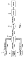
FIGURE 1 depicts a block schematic diagram of a system, in accordance with an aspect of the present principles for encoding, transmitting and decoding video content in accordance with the present principles; -
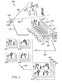
FIGURE 2 illustrates a graphical depiction of a portion of video content with motion in encoded in the High Frame Rate (HFR) mode by the system ofFIG. 1 ; -
FIGURE 3 illustrates a graphical depiction of sequences of a portion of video content with static scenes encoded in the Low Frame Rate (LFR) mode by the system ofFIG. 1 ; -
FIGURE 4 depicts a stream of alternating sequences of video content encoded in HFR and LFR modes, respectively, with each video content sequence having a designation indicating the encoding mode; and -
FIGURE 5 depicts the stream of alternating sequences of video content encoded in HFR and LFR modes ofFIG. 4 following decoding in accordance with the designation associated with each sequence indicating the encoding mode. - In accordance with an aspect of the present principles, a hybrid content transmission technique transmits static scenes of video with high resolution in a Low Frame Rate (LFR) mode (i.e. 4K/30 fps). Conversely, in accordance with the technique of the present principles, scenes with motion in the video content undergo transmission in a High Frame rate (HFR) mode (i.e. HD/120 fps), with such scenes encapsulated in a LFR image block (i.e. 4K/30 fps).
FIGURE 1 illustrates a system 10 for practicing the hybrid transmission technique of the present principles. The system 10 includes anencoder 12 that receives video from a plurality of video sources, including a pair oftelevision cameras FIG. 1 depicts twocameras - In the illustrative example of
FIG. 1 , each of thecameras camera 14, for example, typically provides only relatively static scenes, e.g., scenes of a crowd. Another camera, e.g.,camera 16, typically provide video content with motion, for example the camera provides a video output signal of players engaged in a game, e.g., soccer, baseball, football or the like. - As depicted in
FIG. 1 , the designation provided by each of thecameras - The
encoder 12 receives the video output signal from each of thecameras encoder 12 encodes the video output signal of each of thecameras camera 14, theencoder 12 will encode that video signal in a Low Frame Rate (LFR) mode (e.g., 4K/ 30 fps) if the designation accompanying that video signal indicates that the video has static scenes. Conversely, upon receipt of the video output signal from of thecamera 16, theencoder 12 will encode that video signal in a High Frame Rate (HFR) mode (e.g., 4K, 120 fps); if the designation associated with that camera's video signal indicates that the scenes have motion. Theencoder 12 encodes the video signal from thecamera 16 by encapsulating scenes of the video signal into LFR images block. - In addition to, or in place the video output signals from the
cameras encoder 12 can also receive and encode video signals from one or more off-line content sources, as exemplified by off-line content source 18 which could comprise a storage device or a piece of television studio broadcast equipment. In addition to providing a video output signal to theencoder 12, each off-line content source 18 also provides a designation indicating whether the output video signal from the off-line content source comprises static scenes or scenes with motion. As with each of thecameras line content source 18 could include information designating whether the output signal comprises static scenes or scenes with motion, thereby obviating the need for a separate designation. - As discussed above, the
cameras line content source 18 can provide either kind of video output signal. Indeed, depending on the nature of video being output by the on-line content source 18, an operator could manually adjust the designation set based on the operator's assessment of the video output signal of the off-line source. Alternatively, the off-line content source 18 could generate its designation automatically, based on its analysis of the video content using motion analysis algorithms for example. - The
encoder 12 encodes the video signals received from thecameras line content source 18 to generate an encoded output signal, and an accompanying designation indicating nature of the encoder's video output signal as discussed above. Anetwork 20 transmits the video output signal of theencoder 12 along with the designation of that signal, to adecoder 22 for decoding to yield a decoded video output signal for presentation on adisplay device 24. In practice, thedecoder 22 can comprise part of a set-top box or the like for selecting content for display on thedisplay device 24. In some instances, thedecoder 22 could comprise part of thedisplay device 24. - As discussed above in connection with the
cameras line content source 18, theencoder 12 can include information in its video output signal indicating whether the encoder has encoded that signal in a Low Frame Rate (LFR) or High Frame Rate (HFR) mode. Including information within the encoder video output signal whether the signal is encoded in either a LFR or HFR mode thus will obviate the need to generate a separate designation. - The
decoder 22 decodes video signal received from the encoder in accordance with the accompanying designation indicating whether the incoming signal is LFR or HFR encoded. As discussed above, the incoming video signal received by thedecoder 22 ofFIG. 1 could itself include information the type of encoding (LFR or HFR), thus obviating the need for a separate designation indicating the encoding mode. Using the encoding designation, or in the absence of that designation, the encoding information from the incoming video signal itself, thedecoder 22 can correctly decode the incoming video signal based on whether the incoming signal is LFR or HFR encoded. In the case of an LFR-encoded video signal, each high resolution frame is contained in its own LFR image block and each is delivered at the low frame rate to displaydevice 24. In the case of an HFR-encoded video signal, multiple frames are encapsulated into each LFR image block, as described inUS Provisional Patent Application 62/005,397 decoder 22 will successively extract each one of the multiple frames at the high frame rate for delivery to thedisplay device 24 at the high frame rate. In practice, thedisplay 24 has a digital interface with theencoder 22, for example a High Definition Multimedia Interface (HDMI), to enable the display device to receive separate LFR-mode and HFR-mode video signals. Thedisplay 24 has the capability of switching in real time between the LFR and HFR modes to properly display video signals in each mode. In some embodiments, all of the video signal, both high resolution LFR frames and LFR image blocks containing multiple HFR-encoded frames, is transferred with an interface such as HDMI to a monitor comprising bothdecoder 22 anddisplay 24. - Note that all output from
encoder 12 appears as a higher resolution LFR stream, whether originally provided as LFR images natively at the higher resolution, or HFR images encoded into the higher resolution LFR blocks. The advantage is that intermediate components, e.g.,network 20 which may comprise communication links and video or stream switching elements (not shown), can operate without needing to be aware of the nature of the stream fromencoder 12, particularly if the HFR/LFR mode designation is embedded in the stream. Not until received bydecoder 22 is any element required to process the stream as anything other than an ordinary higher resolution LFR stream. -
FIG. 2 depicts an exemplary framerate compression process 200 in accordance with an aspect of the present principles. As depicted inFIG. 2 , a High Frame Rate (HFR)camera 205, similar to the highframe rate camera 16 ofFIG. 1 , has a field ofview 206 subtending a subject 207. In operation, thecamera 205 will output avideo output signal 201 comprising a stream of HFR images of the subject. Aportion 210 of the HFR image stream generated by thecamera 205 appears inFIG. 2 and consists of individual, sequential frames 211-226. - In the example depicted in
FIG. 2 , the subject 207 comprises a man riding a horse. Images 211-226 of the subject 207 appear inFIG. 2 with an exaggerated timescale so that the individual images exhibit clearly discernable differences. The images depicted come from the work "Jumping a hurdle, black horse" by Eadweard Muybridge, 1887 and were chosen because of they are familiar to many and present a recognizable sequence, which is helpful to the understanding of the present principles. - The images 211-226 of the
portion 210 of the HFR image stream undergo capture duringstep 202, at which time the images accumulate in acapture buffer 230, typically located in thecamera 205 although depicted separately from the camera inFIG. 2 . For ease of processing, the images 211-226 are grouped into sub-sequences 231-234. The sub-sequences of images undergo encoding by theencoder 12 ofFIG. 1 during anencoding process 203 depicted inFIG. 2 . In accordance with an aspect of the present principles, theencoding process 203 packs High Frame Rate (HFR) images into lower-frame rate (LFR) images blocks as described in US Provisional Patent Application 62/005,397 filed May 30, 3014 incorporated by reference herein. For example, the first image from each of the sub-sequences 231-234 is consolidated into the singleLFR image block 241. Likewise, the second image from each sub-sequence is consolidated intoLFR image block 242, and the third image and fourth image from each sub-sequence are packed into LFR image blocks 243 and 244, respectively. In addition to generating the LFR image blocks, thecamera 205 ofFIG. 2 will also generate a designation, as discussed above, which indicated that the camera output signal is encoded in the HFR mode. - In an embodiment that uses image compression, the LFR image blocks 241-244 may be compressed (e.g., "coded") individually, for example using the well-known JPEG or JPEG-2000 compression schemes. If a motion-based compression scheme is chosen, e.g., MPEG-2 or H.264/MPEG-4, then LFR image blocks 241-244 would form an encoded "group of pictures" (GOP) 240. Three kinds of frame encoding are in common use in motion-coded video: I-frames, P-frames, and B-frames. I-frames are "intra coded", that is, the frames are encoded without any reference to other frames, and therefore can stand alone. P-frames or "predicted frames" are encoded relative to a previous reference frame or frames and exploit the redundancies between them for efficient representation (generally a smaller representation as compared to an I-frame). B-frames, or "bidirectional predicted" frames are encoded by exploiting similarities between both prior and later reference frames. A significant portion of the encoding process for P- and B-frames is to identify regions in the reference frame(s) that are also present in the frame being compressed and to estimate the motion of such common regions and encode them as a motion vector. In some embodiments, encoders are allowed to use not just I-frames as references, but other P- or B-frames as well. When suitable, the motion vector representation for a region of the current frame is usually more compact than a more explicit representation for the region's pixels.
- Note that the tiling of the HFR images 211-226 into LFR image blocks 241-244 shown in
FIG. 2 retains the temporal ordering and sequential nature of the sub-sequences 231-234, which provides the advantage that the differences between consecutive HFR frames, for example insub-sequence 232, are maintained after composition in to LFR frames 241-244. Accordingly, since the HFR is higher than the LFR, the expected motion vectors between consecutive HFR frames will generally be smaller than those for a traditionally captured sequence (not shown) at the lower frame rate. Likewise, the corresponding similar regions between consecutively captured frames will generally exhibit more similarity than if the capture frame rate were slower, since less time has passed between consecutive images of the subject at the HFR. Accordingly, the expectation is that compression schemes that exploit motion in the composite images of the encoded GOP 240 will be particularly effective, since within each quadrant of those composite images, the apparent temporal increment between consecutive LFR image blocks 241-244 corresponds to the HFR, even though the image blocks 241-244 of the GOP 240 will be delivered at the LFR. There is, however, a temporal discontinuity in each quadrant between thelast LFR frame 244 of the current encoded GOP 240 and the first LFR frame (not shown) of the next GOP (not shown). The magnitude of this temporal discontinuity in the example ofFIG. 2 is 3x the LFR interval, or 22x the HFR interval. Because of this temporal discontinuity, compression schemes that attempt to exploit similarity between the end of one GOP and the start of the next (i.e., using B-frames), will not fair particularly well and, accordingly, traditional motion encoding techniques in this embodiment is preferably limited to I-frames and P-frames. -
FIG. 3 depicts anexemplary encoding process 300 in accordance with another aspect of the present principles. As depicted inFIG. 2 , a Low Frame Rate (LFR)camera 305, similar to theLFR camera 14 ofFIG. 1 captures a generally static image, illustratively depicted as acrowd 307. In operation, thecamera 305 will output avideo output signal 301 comprising a stream of LFR images of thecrowd 307. Aportion 310 of the LFR image stream generated by thecamera 305 consists of a sequence of LFR frames 310-316. In accordance the teachings of the present principles, theencoding process 300 generates higher resolution LFR images in the form of whole frames at the low frame rate, whereas multiple lower resolution HFR images are encapsulated into each LFR image block 241-244 as described inUS Provisional Patent Application 62/005,397 camera 305 ofFIG. 3 will generate a designation, as discussed above, which indicates that the camera output signal is encoded in the LFR mode. - An encoder, such as
encoder 12 ofFIG. 1 , that receives video signals encoded in both LFR and HFR modes will output a multi-frame output stream, as depicted inFIG. 4 comprised of separate sequences of LFR images, illustratively depicted by LFR sequences 4021 and 4022 and LFR image blocks which encapsulate HFR image sequences, illustratively depicted by LFR image blocks 4041 an 4042. Collectively, the LFR images and the LFR image blocks comprise video content segments. The LFR frame sequences and LFR image blocks (i.e., the video content segments) each have associated designations, represented by theflags FIG. 4 shows an HFR image block and LFR image sequence in alternating fashion, an encoder could output an arbitrarily long succession of LFR image sequences followed by an arbitrary number of HFR image blocks or vice versa. WhileFIG. 4 depicts the LFR image sequences and HFR image blocks as having separate designations, represented by theflags -
FIG. 5 depicts the decoding of the LFR image sequences 4021 and 4022 and LFR image blocks 4041 and 4042 previously discussed in connection withFIG. 4 . A decoder, such as thedecoder 22 ofFIG. 1 , will decode each incoming LFR image sequence and LFR image block in accordance with its accompanying designation (or in the absence of such designation, by examining each image sequence or image block for encoding information incorporated therein). Following decoding, each of the LFR image sequences 4021 and 4022 undergoes display in screens 5021 (only one higher-resolution frame of four shown) and 5022 (only one higher-resolution frame of four shown) inFIG. 5 . Each of the LFR image blocks 4041 and 4042 undergoes decoding to successively strip off the individual lower-resolution HFR images encapsulated within each LFR image block to display the HFR image at the high frame rate as depicted in display screens 5041 (only one lower-resolution frame of sixteen shown) and 5042 (only one lower-resolution frame of sixteen shown), respectively. - The foregoing describes a technique for interchangeably transmitting low and high frame rate video content to maintain high quality video while preserving image detail especially for moving images.
Claims (20)
- A method for transmitting video content segments, comprising:providing a Low Frame Rate LFR and a High Frame Rate HFR encoding mode designations for video content segments having static scenes and scenes with motion, respectively;encoding each video content segment in accordance with its encoding mode designation; andtransmitting the encoded video content with its encoding mode designations to enable retrieval and decoding by a decoder.
- The method according to claim 1 wherein a video content segment having a HFR encoding mode designation is encoded by encapsulating a plurality of HFR images into a LFR image block.
- The method according to claim 1 wherein a video content segment having a LFR encoding mode designation is encoded to yield a sequence of at least one LFR images.
- The method according to claim 1 wherein encoding mode designation includes generating an encoding mode designation separate from the video content segment.
- The method according to claim 1 wherein the encoding mode comprises including an encoding mode designation within the video content segment.
- A method for processing received video content segments, comprising:determining for each received video content segment one of a Low Frame Rate LFR and a High Frame Rate HFR encoding mode designation for that received video content segment indicating whether that segment includes static scenes or scenes with motion, respectively;decoding each video content segment in accordance with its encoding mode designation; andproviding each decoded video content segment to a display device.
- The method according to claim 6 wherein a video content segment having a HFR encoding mode designation is decoded by stripping a plurality of HFR images from encapsulation in a LFR image block.
- The method according to claim 6 wherein a video content segment having a LFR encoding mode designation is decoded to yield a sequence of at least one LFR images.
- The method according to claim 6 wherein the encoding mode designation includes receiving an encoding mode designation separate from the video content segment.
- The method according to claim 6 wherein the encoding mode designation includes examining the video content segment for an incorporated encoding mode designation.
- Apparatus, comprising:an encoder configured to:- receive Low Frame Rate LFR and High Frame Rate HFR encoding mode designations for received video content segments having static scenes and scenes with motion, respectively; and:- encode each video content segment in accordance with its encoding mode.
- The apparatus according to claim 11 wherein the encoder encodes a video content segment having a HFR encoding mode designation by encapsulating a plurality of HFR images into a LFR image block.
- The apparatus according to claim 11 wherein the encoder encodes a video content segment having a LFR encoding mode designation to yield a sequence of at least one LFR images.
- The apparatus according to claim 11 wherein the encoder receives the encoding mode designation separate from the video content segment.
- The apparatus according to claim 11 wherein encoder receives the encoding mode designation as part of the received video content segment.
- Apparatus comprising,
a decoder configured to:- establish for each received encoded video content segment one of a Low Frame Rate (LFR) and a High Frame Rate (HFR) encoding mode designation depending on whether that received encoded video segment includes static scenes or scenes with motion, respectively, and:- decode each received encoded video content segment in accordance with its encoding mode designation. - The apparatus according to claim 16 wherein the decoder decodes a video content segment having a HFR encoding mode designation by stripping a plurality of HFR images from encapsulation in a LFR image block.
- The apparatus according to claim 16 wherein the decoder decodes a video content segment having a LFR encoding mode designation to yield a sequence of at least one LFR images.
- The apparatus according to claim 16 wherein the decoder receives an encoding mode designation separate from the video content segment.
- The apparatus according to claim 16 wherein the decoder can detect an incorporated encoding mode designation within a received video content segment.
Priority Applications (8)
| Application Number | Priority Date | Filing Date | Title |
|---|---|---|---|
| EP14307218.9A EP3041233A1 (en) | 2014-12-31 | 2014-12-31 | High frame rate-low frame rate transmission technique |
| PCT/US2015/066045 WO2016109201A1 (en) | 2014-12-31 | 2015-12-16 | High frame rate-low frame rate transmission technique |
| EP15822935.1A EP3241353A1 (en) | 2014-12-31 | 2015-12-22 | High frame rate-low frame rate transmission technique |
| KR1020177018188A KR20170101227A (en) | 2014-12-31 | 2015-12-22 | High frame rate-low frame rate transmission technique |
| PCT/EP2015/080993 WO2016107792A1 (en) | 2014-12-31 | 2015-12-22 | High frame rate-low frame rate transmission technique |
| CN201580071665.4A CN107113447A (en) | 2014-12-31 | 2015-12-22 | High frame rate low frame rate rate transmission technology |
| US15/541,150 US20180007355A1 (en) | 2014-12-31 | 2015-12-22 | High frame rate-low frame rate transmission technique |
| JP2017533410A JP6573673B2 (en) | 2014-12-31 | 2015-12-22 | High frame rate-low frame rate transmission technology |
Applications Claiming Priority (1)
| Application Number | Priority Date | Filing Date | Title |
|---|---|---|---|
| EP14307218.9A EP3041233A1 (en) | 2014-12-31 | 2014-12-31 | High frame rate-low frame rate transmission technique |
Publications (1)
| Publication Number | Publication Date |
|---|---|
| EP3041233A1 true EP3041233A1 (en) | 2016-07-06 |
Family
ID=52444077
Family Applications (2)
| Application Number | Title | Priority Date | Filing Date |
|---|---|---|---|
| EP14307218.9A Withdrawn EP3041233A1 (en) | 2014-12-31 | 2014-12-31 | High frame rate-low frame rate transmission technique |
| EP15822935.1A Withdrawn EP3241353A1 (en) | 2014-12-31 | 2015-12-22 | High frame rate-low frame rate transmission technique |
Family Applications After (1)
| Application Number | Title | Priority Date | Filing Date |
|---|---|---|---|
| EP15822935.1A Withdrawn EP3241353A1 (en) | 2014-12-31 | 2015-12-22 | High frame rate-low frame rate transmission technique |
Country Status (6)
| Country | Link |
|---|---|
| US (1) | US20180007355A1 (en) |
| EP (2) | EP3041233A1 (en) |
| JP (1) | JP6573673B2 (en) |
| KR (1) | KR20170101227A (en) |
| CN (1) | CN107113447A (en) |
| WO (2) | WO2016109201A1 (en) |
Cited By (1)
| Publication number | Priority date | Publication date | Assignee | Title |
|---|---|---|---|---|
| FR3084552A1 (en) | 2018-07-30 | 2020-01-31 | B<>Com | METHOD FOR FORMING A SEQUENCE OF OUTPUT IMAGES FROM A SEQUENCE OF INPUT IMAGES, METHOD FOR RECONSTRUCTING A SEQUENCE OF INPUT IMAGES FROM A SEQUENCE OF OUTPUT IMAGES, DEVICES, SERVER EQUIPMENT, CUSTOMER EQUIPMENT AND RELATED COMPUTER PROGRAMS |
Families Citing this family (9)
| Publication number | Priority date | Publication date | Assignee | Title |
|---|---|---|---|---|
| WO2016192079A1 (en) * | 2015-06-04 | 2016-12-08 | Intel Corporation | Adaptive batch encoding for slow motion video recording |
| US10846142B2 (en) | 2016-02-23 | 2020-11-24 | Intel Corporation | Graphics processor workload acceleration using a command template for batch usage scenarios |
| US10742708B2 (en) | 2017-02-23 | 2020-08-11 | Netflix, Inc. | Iterative techniques for generating multiple encoded versions of a media title |
| US11153585B2 (en) | 2017-02-23 | 2021-10-19 | Netflix, Inc. | Optimizing encoding operations when generating encoded versions of a media title |
| US10897618B2 (en) | 2017-02-23 | 2021-01-19 | Netflix, Inc. | Techniques for positioning key frames within encoded video sequences |
| US11166034B2 (en) | 2017-02-23 | 2021-11-02 | Netflix, Inc. | Comparing video encoders/decoders using shot-based encoding and a perceptual visual quality metric |
| US10666992B2 (en) | 2017-07-18 | 2020-05-26 | Netflix, Inc. | Encoding techniques for optimizing distortion and bitrate |
| CN108377400A (en) * | 2018-03-07 | 2018-08-07 | 广州图普网络科技有限公司 | A kind of image transmitting optimization method, system and its apparatus |
| US11190826B1 (en) * | 2020-06-25 | 2021-11-30 | Disney Enterprises, Inc. | Segment quality-guided adaptive stream creation |
Citations (3)
| Publication number | Priority date | Publication date | Assignee | Title |
|---|---|---|---|---|
| US20130308697A1 (en) * | 2012-05-18 | 2013-11-21 | Sony Corporation | Image processing apparatus, image processing method, and program |
| DE102014207607A1 (en) * | 2013-04-25 | 2014-10-30 | Broadcom Corporation | System and method for processing video data |
| US20140320740A1 (en) * | 2013-04-25 | 2014-10-30 | Broadcom Corporation | System and method for processing video data |
Family Cites Families (17)
| Publication number | Priority date | Publication date | Assignee | Title |
|---|---|---|---|---|
| ATE454016T1 (en) * | 2001-09-12 | 2010-01-15 | Panasonic Corp | IMAGE CODING AND DECODING METHODS |
| JP4196726B2 (en) * | 2003-05-14 | 2008-12-17 | ソニー株式会社 | Image processing apparatus, image processing method, recording medium, and program |
| US20050201469A1 (en) * | 2004-03-11 | 2005-09-15 | John Sievers | Method and apparatus for improving the average image refresh rate in a compressed video bitstream |
| KR100896279B1 (en) * | 2005-04-15 | 2009-05-07 | 엘지전자 주식회사 | Method for scalably encoding and decoding video signal |
| JP4542107B2 (en) * | 2005-07-22 | 2010-09-08 | 三菱電機株式会社 | Image decoding apparatus and image decoding method |
| US20090034857A1 (en) * | 2005-07-22 | 2009-02-05 | Mitsubishi Electric Corporation | Image encoder and image decoder, image encoding method and image decoding method, image encoding program and image decoding program, and computer readable recording medium recorded with image encoding program and computer readable recording medium recorded with image decoding program |
| US8463061B2 (en) * | 2006-07-13 | 2013-06-11 | Nec Corporation | Encoding and decoding two-dimensional signal using a wavelet transform |
| US8582663B2 (en) * | 2006-08-08 | 2013-11-12 | Core Wireless Licensing S.A.R.L. | Method, device, and system for multiplexing of video streams |
| US8345083B2 (en) * | 2007-07-31 | 2013-01-01 | Cisco Technology, Inc. | Dynamic management of picture quality in a video conference with diversified constraints |
| US20110280311A1 (en) * | 2010-05-13 | 2011-11-17 | Qualcomm Incorporated | One-stream coding for asymmetric stereo video |
| CN104641638B (en) * | 2012-06-28 | 2018-08-03 | 阿克西斯股份公司 | The system and method that video content is encoded using virtual intra frame |
| AU2013321333B2 (en) * | 2012-09-28 | 2017-07-27 | Sony Corporation | Image processing device and method |
| CN109068136B (en) * | 2012-12-18 | 2022-07-19 | 索尼公司 | Image processing apparatus, image processing method, and computer-readable storage medium |
| JP6331103B2 (en) * | 2013-03-21 | 2018-05-30 | ソニー株式会社 | Image decoding apparatus and method |
| US10085034B2 (en) * | 2013-07-12 | 2018-09-25 | Sony Corporation | Image coding apparatus and method |
| US20150163486A1 (en) * | 2013-12-09 | 2015-06-11 | Vixs Systems Inc. | Variable bitrate encoding |
| JP6463041B2 (en) * | 2014-08-28 | 2019-01-30 | キヤノン株式会社 | Image processing apparatus, image processing method, and program |
-
2014
- 2014-12-31 EP EP14307218.9A patent/EP3041233A1/en not_active Withdrawn
-
2015
- 2015-12-16 WO PCT/US2015/066045 patent/WO2016109201A1/en active Application Filing
- 2015-12-22 EP EP15822935.1A patent/EP3241353A1/en not_active Withdrawn
- 2015-12-22 WO PCT/EP2015/080993 patent/WO2016107792A1/en active Application Filing
- 2015-12-22 US US15/541,150 patent/US20180007355A1/en not_active Abandoned
- 2015-12-22 KR KR1020177018188A patent/KR20170101227A/en unknown
- 2015-12-22 JP JP2017533410A patent/JP6573673B2/en not_active Expired - Fee Related
- 2015-12-22 CN CN201580071665.4A patent/CN107113447A/en active Pending
Patent Citations (3)
| Publication number | Priority date | Publication date | Assignee | Title |
|---|---|---|---|---|
| US20130308697A1 (en) * | 2012-05-18 | 2013-11-21 | Sony Corporation | Image processing apparatus, image processing method, and program |
| DE102014207607A1 (en) * | 2013-04-25 | 2014-10-30 | Broadcom Corporation | System and method for processing video data |
| US20140320740A1 (en) * | 2013-04-25 | 2014-10-30 | Broadcom Corporation | System and method for processing video data |
Cited By (3)
| Publication number | Priority date | Publication date | Assignee | Title |
|---|---|---|---|---|
| FR3084552A1 (en) | 2018-07-30 | 2020-01-31 | B<>Com | METHOD FOR FORMING A SEQUENCE OF OUTPUT IMAGES FROM A SEQUENCE OF INPUT IMAGES, METHOD FOR RECONSTRUCTING A SEQUENCE OF INPUT IMAGES FROM A SEQUENCE OF OUTPUT IMAGES, DEVICES, SERVER EQUIPMENT, CUSTOMER EQUIPMENT AND RELATED COMPUTER PROGRAMS |
| WO2020025510A1 (en) | 2018-07-30 | 2020-02-06 | Fondation B-Com | Method for forming an output image sequence from an input image sequence, method for reconstructing an input image sequence from an output image sequence, associated devices, server equipment, client equipment and computer programs |
| US11601617B2 (en) | 2018-07-30 | 2023-03-07 | Fondation B-Com | Method for forming an output image sequence from an input image sequence, method for reconstructing an input image sequence from an output image sequence, associated devices, server equipment, client equipment and computer programs |
Also Published As
| Publication number | Publication date |
|---|---|
| CN107113447A (en) | 2017-08-29 |
| WO2016107792A1 (en) | 2016-07-07 |
| WO2016109201A1 (en) | 2016-07-07 |
| JP6573673B2 (en) | 2019-09-11 |
| JP2018510524A (en) | 2018-04-12 |
| US20180007355A1 (en) | 2018-01-04 |
| EP3241353A1 (en) | 2017-11-08 |
| KR20170101227A (en) | 2017-09-05 |
Similar Documents
| Publication | Publication Date | Title |
|---|---|---|
| EP3041233A1 (en) | High frame rate-low frame rate transmission technique | |
| US20180255272A1 (en) | Transmission device, transmission method, reception device, and reception method | |
| KR102558495B1 (en) | A video encoding/decoding method for signaling HLS, a computer readable recording medium storing an apparatus and a bitstream | |
| US11695934B2 (en) | Mixed NAL unit type based-video encoding/decoding method and apparatus, and method for transmitting bitstream | |
| US11902556B2 (en) | Mixed NAL unit type-based image encoding/decoding method and device, and method for transmitting bitstream | |
| AU2016309262B2 (en) | Transmission device, transmission method, reception device, and reception method | |
| US20170105019A1 (en) | High frame rate tiling compression technique | |
| US20190327465A1 (en) | Image processing device and method | |
| Kunić et al. | Beyond HDTV technology | |
| US11818380B2 (en) | Image encoding/decoding method and device based on hybrid NAL unit type, and recording medium for storing bitstream | |
| CN113545060A (en) | Empty tile coding in video coding | |
| RU2806784C1 (en) | Method and device for image encoding/decoding based on mixed type nal unit and method for transmitting bit stream | |
| RU2812029C2 (en) | Method and device for image encoding/decoding based on mixed type nal unit and method for transmitting bit stream | |
| RU2787713C2 (en) | Method and device for chromaticity block prediction | |
| JP2008244667A (en) | Image transmission device | |
| KR20220160043A (en) | Video encoding/decoding method, apparatus and recording medium for storing a bitstream based on a hybrid NAL unit type | |
| JP2024063177A (en) | Image encoding/decoding method and apparatus based on hybrid NAL unit type and method for transmitting bitstream | |
| KR101609798B1 (en) | moving picture replay device |
Legal Events
| Date | Code | Title | Description |
|---|---|---|---|
| PUAI | Public reference made under article 153(3) epc to a published international application that has entered the european phase |
Free format text: ORIGINAL CODE: 0009012 |
|
| AK | Designated contracting states |
Kind code of ref document: A1 Designated state(s): AL AT BE BG CH CY CZ DE DK EE ES FI FR GB GR HR HU IE IS IT LI LT LU LV MC MK MT NL NO PL PT RO RS SE SI SK SM TR |
|
| AX | Request for extension of the european patent |
Extension state: BA ME |
|
| STAA | Information on the status of an ep patent application or granted ep patent |
Free format text: STATUS: THE APPLICATION IS DEEMED TO BE WITHDRAWN |
|
| 18D | Application deemed to be withdrawn |
Effective date: 20170110 |