EP3040237A1 - Transport machine - Google Patents
Transport machine Download PDFInfo
- Publication number
- EP3040237A1 EP3040237A1 EP14848515.4A EP14848515A EP3040237A1 EP 3040237 A1 EP3040237 A1 EP 3040237A1 EP 14848515 A EP14848515 A EP 14848515A EP 3040237 A1 EP3040237 A1 EP 3040237A1
- Authority
- EP
- European Patent Office
- Prior art keywords
- vessel
- transport machine
- load
- detection
- vehicle body
- Prior art date
- Legal status (The legal status is an assumption and is not a legal conclusion. Google has not performed a legal analysis and makes no representation as to the accuracy of the status listed.)
- Granted
Links
- 238000001514 detection method Methods 0.000 claims abstract description 180
- 238000010586 diagram Methods 0.000 description 34
- 238000003384 imaging method Methods 0.000 description 33
- 238000004891 communication Methods 0.000 description 28
- 238000005065 mining Methods 0.000 description 27
- 230000006870 function Effects 0.000 description 19
- 230000001133 acceleration Effects 0.000 description 8
- 238000000034 method Methods 0.000 description 7
- 238000000605 extraction Methods 0.000 description 6
- 239000000470 constituent Substances 0.000 description 5
- 230000003287 optical effect Effects 0.000 description 4
- 230000005540 biological transmission Effects 0.000 description 3
- 210000003462 vein Anatomy 0.000 description 3
- 239000000446 fuel Substances 0.000 description 2
- 230000000149 penetrating effect Effects 0.000 description 2
- 230000000630 rising effect Effects 0.000 description 2
- 238000004590 computer program Methods 0.000 description 1
- 230000003247 decreasing effect Effects 0.000 description 1
- 238000007599 discharging Methods 0.000 description 1
- 230000000694 effects Effects 0.000 description 1
- 239000004973 liquid crystal related substance Substances 0.000 description 1
- 239000011435 rock Substances 0.000 description 1
- 239000007787 solid Substances 0.000 description 1
- 239000000126 substance Substances 0.000 description 1
Images


Classifications
-
- B—PERFORMING OPERATIONS; TRANSPORTING
- B60—VEHICLES IN GENERAL
- B60P—VEHICLES ADAPTED FOR LOAD TRANSPORTATION OR TO TRANSPORT, TO CARRY, OR TO COMPRISE SPECIAL LOADS OR OBJECTS
- B60P1/00—Vehicles predominantly for transporting loads and modified to facilitate loading, consolidating the load, or unloading
- B60P1/04—Vehicles predominantly for transporting loads and modified to facilitate loading, consolidating the load, or unloading with a tipping movement of load-transporting element
- B60P1/30—Vehicles predominantly for transporting loads and modified to facilitate loading, consolidating the load, or unloading with a tipping movement of load-transporting element in combination with another movement of the element
- B60P1/32—Vehicles predominantly for transporting loads and modified to facilitate loading, consolidating the load, or unloading with a tipping movement of load-transporting element in combination with another movement of the element the other movement being lateral displacement
-
- B—PERFORMING OPERATIONS; TRANSPORTING
- B65—CONVEYING; PACKING; STORING; HANDLING THIN OR FILAMENTARY MATERIAL
- B65G—TRANSPORT OR STORAGE DEVICES, e.g. CONVEYORS FOR LOADING OR TIPPING, SHOP CONVEYOR SYSTEMS OR PNEUMATIC TUBE CONVEYORS
- B65G67/00—Loading or unloading vehicles
- B65G67/02—Loading or unloading land vehicles
- B65G67/04—Loading land vehicles
-
- B—PERFORMING OPERATIONS; TRANSPORTING
- B65—CONVEYING; PACKING; STORING; HANDLING THIN OR FILAMENTARY MATERIAL
- B65G—TRANSPORT OR STORAGE DEVICES, e.g. CONVEYORS FOR LOADING OR TIPPING, SHOP CONVEYOR SYSTEMS OR PNEUMATIC TUBE CONVEYORS
- B65G67/00—Loading or unloading vehicles
- B65G67/02—Loading or unloading land vehicles
- B65G67/24—Unloading land vehicles
-
- E—FIXED CONSTRUCTIONS
- E02—HYDRAULIC ENGINEERING; FOUNDATIONS; SOIL SHIFTING
- E02F—DREDGING; SOIL-SHIFTING
- E02F3/00—Dredgers; Soil-shifting machines
- E02F3/04—Dredgers; Soil-shifting machines mechanically-driven
- E02F3/18—Dredgers; Soil-shifting machines mechanically-driven with digging wheels turning round an axis, e.g. bucket-type wheels
- E02F3/20—Dredgers; Soil-shifting machines mechanically-driven with digging wheels turning round an axis, e.g. bucket-type wheels with tools that only loosen the material, i.e. mill-type wheels
-
- E—FIXED CONSTRUCTIONS
- E02—HYDRAULIC ENGINEERING; FOUNDATIONS; SOIL SHIFTING
- E02F—DREDGING; SOIL-SHIFTING
- E02F7/00—Equipment for conveying or separating excavated material
- E02F7/02—Conveying equipment mounted on a dredger
- E02F7/026—Conveying equipment mounted on a dredger mounted on machines equipped with dipper- or bucket-arms
-
- E—FIXED CONSTRUCTIONS
- E02—HYDRAULIC ENGINEERING; FOUNDATIONS; SOIL SHIFTING
- E02F—DREDGING; SOIL-SHIFTING
- E02F9/00—Component parts of dredgers or soil-shifting machines, not restricted to one of the kinds covered by groups E02F3/00 - E02F7/00
- E02F9/20—Drives; Control devices
- E02F9/2025—Particular purposes of control systems not otherwise provided for
- E02F9/205—Remotely operated machines, e.g. unmanned vehicles
-
- E—FIXED CONSTRUCTIONS
- E21—EARTH OR ROCK DRILLING; MINING
- E21C—MINING OR QUARRYING
- E21C41/00—Methods of underground or surface mining; Layouts therefor
- E21C41/16—Methods of underground mining; Layouts therefor
-
- E—FIXED CONSTRUCTIONS
- E21—EARTH OR ROCK DRILLING; MINING
- E21F—SAFETY DEVICES, TRANSPORT, FILLING-UP, RESCUE, VENTILATION, OR DRAINING IN OR OF MINES OR TUNNELS
- E21F13/00—Transport specially adapted to underground conditions
- E21F13/02—Transport of mined mineral in galleries
- E21F13/025—Shuttle cars
-
- B—PERFORMING OPERATIONS; TRANSPORTING
- B60—VEHICLES IN GENERAL
- B60P—VEHICLES ADAPTED FOR LOAD TRANSPORTATION OR TO TRANSPORT, TO CARRY, OR TO COMPRISE SPECIAL LOADS OR OBJECTS
- B60P1/00—Vehicles predominantly for transporting loads and modified to facilitate loading, consolidating the load, or unloading
- B60P1/04—Vehicles predominantly for transporting loads and modified to facilitate loading, consolidating the load, or unloading with a tipping movement of load-transporting element
- B60P1/28—Tipping body constructions
Definitions
- the load detection device can be configured to detect a form of a load of the vessel, and based on a result of detection by the load detection device, the vessel can be configured to move in the lateral direction by the slide mechanism such that a position of the vessel is adjusted with respect to a loading machine that loads a load onto the vessel.
- the load detection device can be configured to detect a weight of the load of the vessel, and based on a result of detection by the load detection device, the vessel can be configured to move in the lateral direction by the slide mechanism such that a position of the vessel is adjusted with respect to a loading machine that loads a load onto the vessel.
- a road surface of the tunnel R along which the transport machine 1 travels and an X 0 Y 0 plane (horizontal surface) are substantially parallel.
- the road surface of tunnel R has, in many cases, irregularities, uphill slopes, and downhill slopes.
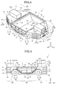
- FIG. 4 is a perspective view of an exemplary transport machine 1.
- FIG. 5 is a side view of an exemplary transport machine 1.
- FIG. 6 is a top view of an exemplary transport machine 1.
- FIG. 7 is a front view of an exemplary transport machine 1.
- the transport machine 1 includes a traveling device 5, a vehicle body 6, and a vessel 7. At least a portion of the vehicle body 6 is arranged above the traveling device 5. The vessel 7 is supported by the vehicle body 6.
- the front section 6A includes a holding section 13 that removably holds a device 12.
- the rear section 6B includes a holding section 14 that removably holds the device 12.
- the device 12 includes a battery.
- Each of the holding section 13 and the holding section 14 has a connector through which power is supplied from a battery 12.
- An electronic device and an electric motor included in the transport machine 1 are operated by power supplied from the battery 12.
- a portion of the vessel 7, arranged in front of the center AX of the vehicle body 6, and a portion of the vessel 7, arranged in rear of the center AX of the vehicle body 6, with respect to the Y-axis direction, are arranged symmetrically.
- being symmetric means that, with respect to a virtual plane (symmetrical plane) that passes through the center AX and is parallel with the XZ plane, a portion arranged in one side (+Y side, front side) and another side (-Y side, rear side) are mirror-symmetrical.
- a portion of the vessel 7, which is arranged in the right direction from the center AX of the vehicle body 6, and a portion of the vessel 7, which is arranged in the left direction from the center AX of the vehicle body 6, are arranged symmetrically with respect to the X-axis direction.
- being symmetric means that, with respect to a virtual surface (symmetrical surface) that passes through the center AX and is parallel with the YZ plane, a portion arranged in one side (+X side, right side) and another side (-X side, left side) are mirror-symmetrical.
- the upper surface 34A and the upper surface 34B are equally formed.
- the recess 37 and the holding section 13 are arranged at a central portion of the front section 6A with respect to the X-axis direction. As described above, the vehicle body 6 is left/right symmetrical.
- the front wheel driving device 10 includes an electric motor (in-wheel motor) 16 at least a portion of which is arranged in a hub of the front wheel 8.
- the electric motor 16 operates on power supplied from the battery 12. Power is supplied to the electric motor 16 of the front wheel driving device 10 from the battery 12 held by the holding section 13 of the front section 6A.
- the electric motor 16 for driving the front wheel 8 operates on the power supplied from the battery 12 held by the holding section 13 of the front section 6A.
- the electric motor 16 is provided for each of two front wheels 8.
- the slide mechanism 18 can move the vessel 7 such that at least a portion of the vessel 7 is arranged on each of one or another side of the vehicle body 6 with respect to the X-axis direction.
- the slide mechanism 18 can move the vessel 7 in the +X direction, by using the hydraulic cylinder 22, such that one side surface 7C on the vessel 7 is arranged outside one side surface 32 and one side surface 42 of the vehicle body 6.
- the slide mechanism 18 can move the vessel 7 in the -X direction, by using the hydraulic cylinder 22, such that the other side surface 7D on the vessel 7 is arranged outside the other side surface 33 and the other side surface 43 of the vehicle body 6. In this manner, the slide mechanism 18 slides the vessel 7 to both sides with respect to the X-axis direction.
- the transport machine 1 includes a processing device 51, a storage device 52, a communication device 53, and the detection system 60.
- the detection system 60 includes a range sensor 61, a non-contact sensor 62, a weight sensor 63, an imaging device 64, a reading device 65, a speed sensor 66, an acceleration sensor 67, and a steering sensor 68.
- the range sensor 61 outputs physical shape data of a space.
- the non-contact sensor 62 detects an obstacle.
- the weight sensor 63 detect the weight of the vessel 7.
- the imaging device 64 can obtain an optical image of an object and detect the form of the object.
- the reading device 65 detects a mark M (refer to FIG. 14 ) provided on the drift DR.
- the speed sensor 66 detects a traveling speed of the transport machine 1.
- the acceleration sensor 67 detects acceleration or an angular speed of the transport machine 1.
- the steering sensor 68 detects at least one of steering angles of the front wheel 8 and the rear wheel 9.
- the storage device 52 includes at least one of random access memory (RAM), read only memory (ROM), flash memory, and a hard disk drive, and is connected with the processing device 51.
- the storage device 52 stores various types of information required for autonomous traveling.
- the information regarding the position of the mark M (absolute position) in the drift DR is known information measured beforehand.
- Information regarding the absolute position of the mark M is stored in the storage device 52.
- the processing device 51 can obtain the absolute position of the transport machine 1 in the drift DR based on the result of detection on the mark M detected by the reading device 65 provided on the transport machine 1, namely, identification information or specific information on the mark M and based on stored information in the storage device 52. That is, the reading device 65 can also function as a position detection device that detects the position of the transport machine 1 that travels along the drift DR (tunnel R). The reading device 65 also functions as the second detection device to detect the mark M provided on the drift DR (tunnel R).
- the imaging device 64 may be arranged at a predetermine position on the vehicle body 6, where an optical image of the loading machine 2 is obtainable.
- the imaging device 64 may be arranged at a predetermined position on the vehicle body 6, where an optical image of the wall surface of the drift DR (three-dimensional form data) is obtainable.
- the imaging device 64 functions as at least one of a loading machine detection device (first detection device) that detects the loading machine 2 and a second loading machine that detects the drift DR (tunnel R).
- a range sensor (second detection device, position detection device, loading machine detection device, and first detection device) 61 that can detect at least one of shape data of the loading machine 2, shape data of a wall surface of the drift DR, the relative position with respect to the loading machine 2, and the relative position with respect to the wall surface of the drift DR is arranged at a predetermined position of the vehicle body 6.
- the range sensor 61 is arranged on a side surface of the vehicle body 6 such that at least one of the shape data of the wall surface of the drift DR, and the relative position with respect to the wall surface of the drift DR is detectable.
- the range sensor 61 may be arranged at least on a portion of the top surface, the side surface, the front surface, and the rear surface, of the vehicle body 6, such that at least one of the shape data of the loading machine 2, and the relative position of the loading machine 2 is detectable.
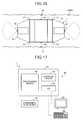
- FIG. 17 is a block diagram illustrating an exemplary management device 80 according to the present embodiment.
- the management device 80 includes a computer system 81, a display device 85, an input device 86, and a communication device 87.
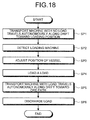
- FIG. 18 is a flowchart illustrating exemplary operation of the transport machine 1 according to the present embodiment.
- the transport machine 1 with no load travels along the drift DR toward the loading position LP in order to pick the load (step SP1).
- the center of the vessel 7 and the center of the vehicle body 6 overlap with each other with respect to the X-axis direction. Accordingly, the vessel 7 is not lifted up.
- Information regarding the route CS is transmitted from the management device 80 to the transport machine 1 via the communication system 4.
- the transmitted information is stored in the storage device 52 of the transport machine 1.
- the route CS is a route based on the absolute position.
- the transport machine 1 may contact the wall surface of the drift DR.
- the transport machine 1 may travel while contacting the wall surface of the drift DR.
- a guide member e.g. guide rail
- a guided portion e.g. roller
- the processing device 51 By obtaining the form data of the loading machine 2 and detecting the relative position with respect to the loading machine 2, it is possible for the processing device 51 to arrange the vessel 7 to a position suitable for loading operation.
- the processing device 51 based on the result of detection by the range sensor 61, arranges the vessel 7 at the loading position LP so as to prevent the transport machine 1 including the vessel 7 and the loading machine 2 from coming in contact with each other.
- the processing device 51 controls the slide mechanism 18 such that the vessel 7 is arranged below the supply unit of the feeder device 91 arranged on the +X side.
- the processing device 51 controls the slide mechanism 18 based on the result of detection by the range sensor 61 so as to move the vessel 7 in the +X direction and adjust the position of the vessel 7 with respect to the loading machine 2.
- the processing device 51 in a state where the position of the vehicle body 6 is fixed, moves the vessel 7 by using the slide mechanism 18 so as to arrange the vessel 7 at the loading position LP.
- the processing device 51 may determine whether to reciprocate the vessel 7 or may determine one or both of amplitude and speed of reciprocation based on the result of detection by the imaging device 64 that detects the form of the load of the vessel 7 and based on the result of detection by the weight sensor 63 that detects the weight of the vessel 7. For example, in a case where it is determined that the vessel 7 is full of load based on the result of detection by the imaging device 64 and at the same time, it is determined that the vessel 7 is not yet full of load based on the result of detection by the weight sensor 63, it is estimated that there are numerous gaps between the ores loaded on the vessel 7.
- the processing device 51 derives the absolute position of the transport machine 1 at the drift DR based on the result of detection by at least one of the range sensor 61 and the reading device 65, and based on the information stored in the storage device 52. The processing device 51, then, controls the traveling device 5 such that the transport machine 1 travels along the drift DR according to the route CS toward the ore path OP. The processing device 51, based on at least one of the result of detection by the range sensor 61 and the result of detection by the reading device 65, controls the traveling device 5 at the drift DR toward the ore path OP such that the vessel 7 is arranged at the ore path OP.
- FIG. 22 is a diagram illustrating an exemplary state in which a load is being discharged from the vessel 7 at the ore path OP.
- the processing device 51 lifts up the vessel 7 by operating the side dump mechanism 19. With this operation, as illustrated in FIG. 22 , the side gate 25 pivots along with rising operation of the vessel 7, so as to form the opening 7K between the vessel main body 24 and the side gate 25.
- the load on the vessel 7 is discharged from the vessel 7 via the opening 7K (step SP6).
- the vessel 7 is lifted up such that the load is discharged onto the -X side of the vehicle body 6.
- the processing device 51 may detect relative positions of the transport machine 1 and the loading machine 2, which is arranged on the -X side with respect to the transport machine 1 by using the range sensor 61 such that the vessel 7 is arranged at the loading position LP arranged on the -X side with respect to the transport machine 1 traveling along the drift DR in the +Y 0 direction. Based on the result of detection, the processing device 51 may adjust the position of the vessel 7 with respect to the loading machine 2 by controlling the slide mechanism 18 to move the vessel 7 in the -X direction such that the vessel 7 is arranged below the supply unit of the feeder device 91 of the loading machine 2.
- the processing device 51 may control the traveling device 5 to prevent the transport machine 1 and the obstacle from coming in contact with each other. Specifically, the processing device 51 may cause the transport machine 1 to stop traveling, to move reversely, or to travel while avoiding the obstacle.
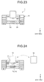
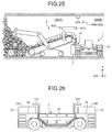
- FIG. 25 is a diagram illustrating an exemplary range sensor 612 of the detection system 602 mounted on the loading machine 2, and an exemplary range sensor 61D of the detection system 60D arranged in the tunnel R.
- the range sensor 61 arranged on the transport machine 1.
- the relative positions of the transport machine 1 and the loading machine 2 may be detected by the range sensor (position detection device) 612 provided on the loading machine 2.
- a result of detection on the relative positions may be transmitted from the loading machine 2 to the transport machine 1, or may be transmitted from the loading machine 2 to the transport machine 1 via the management device 80.
- the processing device 51 of the transport machine 1 may adjust the position of the vessel 7 such that the vessel 7 is arranged at the loading position LP of the loading machine 2, based on a result of detection by of the range sensor 612.
- the processing device 51 may adjust the position of the vessel 7 by using the slide mechanism 18, or by using the traveling device 5.
- the management device 80 based on the result of detection by the range sensor 612, may transmit a command signal to the support device 17 and the traveling device 5 such that the vessel 7 is arranged at the loading position LP.
- the management device 80 may remotely operate the transport machine 1.
- the relative positions of the transport machine 1 and the wall surface of the drift DR, or the absolute position of the transport machine 1 are detected by the detection system 60 including the range sensor 61 and the reading device 65, arranged on the transport machine 1.
- the drift DR may be provided with a plurality of reading devices that can read identifiers arranged on the transport machine 1.
- the absolute position of the transport machine 1 may be obtained based on a result of detection by the reading device.
- the reading device functions as a position detection device that detects the position of the transport machine 1 traveling on the drift DR (tunnel R).
- a plurality of range sensors 61D capable of detecting the relative position with respect to the transport machine 1.
- the traveling device 5 of the transport machine 1 may be controlled on the drift DR toward a target position (loading position LP, ore path OP, or the like) such that the vessel 7 of the transport machine 1 is arranged at the target position, based on a result of detection by the detection system 60D provided on the drift DR.
- the traveling device 5 may be controlled by the management device 80. Specifically, based on the result of detection by the detection system 60D arranged on the drift DR, the management device 80 may transmit a command signal for moving the transport machine 1 to the target position, and the traveling device 5 may travel based on the command signal. In short, the management device 80 may remotely operate the transport machine 1.
- the configuration may be such that both the holding section 13 and the holding section 14 removably hold the device 12; or any one of the holding section 13 and the holding section 14 removably holds the device 12 and the other one unremovably holds the device 12.
- the imaging device 64 that detects the form of the load (appearance of load) of the vessel 7. Accordingly, based on the result of detection by the imaging device 64, it is possible to adjust the position of the vessel 7 with respect to the supply unit of the feeder device 91 and to reciprocate the vessel 7 so as to obtain a form of load in a desired shape. With this configuration, it is possible to suppress load collapse or load dropping and to transport the load in a state with the full-capacity rate of the load on the vessel 7 being high.
Landscapes
- Engineering & Computer Science (AREA)
- Mining & Mineral Resources (AREA)
- Mechanical Engineering (AREA)
- Civil Engineering (AREA)
- Structural Engineering (AREA)
- General Engineering & Computer Science (AREA)
- Life Sciences & Earth Sciences (AREA)
- Aviation & Aerospace Engineering (AREA)
- Geology (AREA)
- Geochemistry & Mineralogy (AREA)
- General Life Sciences & Earth Sciences (AREA)
- Remote Sensing (AREA)
- Transportation (AREA)
- Arrangement Or Mounting Of Propulsion Units For Vehicles (AREA)
- Control Of Position, Course, Altitude, Or Attitude Of Moving Bodies (AREA)
Abstract
Description
- The present invention relates to a transport machine.
- As a mining method in a mine, a surface mining and an underground mining are known. In the surface mining, mining is performed from a surface of the earth. In the underground mining, mining is performed from underground. In recent years, there are many cases where underground mining is employed, in view of its reduced burden on the environment, and increasing depth of locations of ore deposits.
Patent Literature 1 discloses an exemplary technique regarding a transport machine operating inside an underground mine. - Patent Literature 1:
US 7,899,599 - The transport machine used for underground mining operates in an environment different from an environment of surface mining. For example, the transport machine is required to travel in a tunnel. Therefore, the transport machine used for underground mining needs to have a form suitable for the environment of underground mining.
- The present invention is intended to provide a transport machine capable of performing operation smoothly even on a site of underground mining
- According to the present invention, a transport machine comprises: a traveling device; a vehicle body arranged above the traveling device; a vessel provided on the vehicle body; a support device including a slide mechanism configured to move the vessel in a lateral direction with respect to the vehicle body, the lateral direction intersecting with a traveling direction of the traveling device when the transport machine travels straight; and a load detection device configure to detect a state of a load on the vessel, wherein the slide mechanism is controlled based on a result of detection by the load detection device.
- In the present invention, in one or both of cases where the load is loaded onto the vessel and the load is discharged from the vessel, the slide mechanism can be configured to move the vessel such that at least a portion of the vessel is arranged outside the vehicle body.
- In the present invention, the slide mechanism can be capable of moving the vessel such that at least a portion of the vessel is arranged on each of one and other sides of the vehicle body with respect to the lateral direction.
- In the present invention, the load detection device can be configured to detect a form of a load of the vessel, and based on a result of detection by the load detection device, the vessel can be configured to move in the lateral direction by the slide mechanism such that a position of the vessel is adjusted with respect to a loading machine that loads a load onto the vessel.
- In the present invention, wherein the load detection device can be configured to detect a weight of the load of the vessel, and based on a result of detection by the load detection device, the vessel can be configured to move in the lateral direction by the slide mechanism such that a position of the vessel is adjusted with respect to a loading machine that loads a load onto the vessel.
- In the present invention, the transport machine can comprise: a loading machine detection device configured to detect a loading machine that loads a load onto the vessel, wherein, based on a result of detection by the loading machine detection device, the vessel can be configured to move in the lateral direction by the slide mechanism such that a position of the vessel is adjusted with respect to the loading machine.
- In the present invention, the slide mechanism can be configured to reciprocate the vessel with respect to the lateral direction.
- In the present invention, the slide mechanism can be configured to reciprocate the vessel in one or both of a loading operation period in which a load is loaded on the vessel and a period after the loading operation period.
- In the present invention, the transport machine can comprise: the load detection device configured to detect a state of a load of the vessel, and wherein an amplitude of reciprocation of the vessel can be determined based on a result of detection by the load detection device.
- In the present invention, the transport machine can comprise: a form detection device configured to detect a form of a load of the vessel; and a weight detection device configured to detect a weight of the vessel, wherein whether to reciprocate the vessel can be determined based on a result of detection by the form detection device and a result of detection by the weight detection device.
- In the present invention, the support device can include a side dump mechanism configured to discharge a load of the vessel to the lateral direction intersecting with the traveling direction.
- In the present invention, the traveling device can include a front wheel and a rear wheel, the vehicle body can include a recess arranged between the front wheel and the rear wheel, and at least a portion of the vessel can be arranged at the recess.
- In the present invention, the vehicle body can include a front section, at least a portion of the front section being arranged above the front wheel, the vehicle body can include a rear section, at least a portion of the rear section being arranged above the rear wheel, the recess can be arranged between the front section and the rear section, and an upper surface of the vessel can be arranged below an upper surface of the front section and an upper surface of the rear section.
- According to the present invention, it is possible to provide a transport machine capable of performing operation smoothly even on a site of underground mining.
-
-
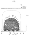
FIG. 1 is a schematic diagram illustrating an exemplary mining site according to the present embodiment. -
FIG. 2 is a schematic diagram illustrating an exemplary tunnel according to the present embodiment. -
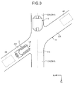
FIG. 3 is a partially enlarged diagram ofFIG. 2 . -
FIG. 4 is a perspective view of an exemplary transport machine according to the present embodiment. -
FIG. 5 is a side view of an exemplary transport machine according to the present embodiment. -
FIG. 6 is a top view of an exemplary transport machine according to the present embodiment. -
FIG. 7 is a front view of an exemplary transport machine according to the present embodiment. -
FIG. 8 is a schematic diagram illustrating an exemplary traveling device according to the present embodiment. -
FIG. 9 is a schematic diagram illustrating an exemplary traveling device according to the present embodiment. -
FIG. 10 is a schematic diagram illustrating an exemplary support device according to the present embodiment. -
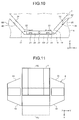
FIG. 11 is a schematic diagram illustrating exemplary operation of a vessel according to the present embodiment. -
FIG. 12 is a schematic diagram illustrating exemplary operation of the vessel according to the present embodiment. -
FIG. 13 is a schematic diagram illustrating exemplary operation of the vessel according to the present embodiment. -
FIG. 14 is a block diagram illustrating an exemplary processing device and detection system according to the present embodiment. -
FIG. 15 is a schematic diagram illustrating an exemplary detection system according to the present embodiment. -
FIG. 16 is a schematic diagram illustrating an exemplary detection system according to the present embodiment. -
FIG. 17 is a block diagram illustrating an exemplary management device according to the present embodiment. -
FIG. 18 is a flowchart illustrating exemplary operation of the transport machine according to the present embodiment. -
FIG. 19 is a perspective view of an exemplary state in which a load is being loaded onto a transport machine from a loading machine according to the present embodiment. -
FIG. 20 is a side view of an exemplary state in which a load is being loaded onto a transport machine from the loading machine according to the present embodiment. -
FIG. 21 is a schematic diagram illustrating an exemplary state in which a load is being loaded onto a vessel from the loading machine according to the present embodiment. -
FIG. 22 is a diagram illustrating an exemplary state in which a load is being discharged from the transport machine according to the present embodiment. -
FIG. 23 is a front view of an exemplary transport machine according to the present embodiment. -
FIG. 24 is a schematic diagram illustrating exemplary operation of replacing a device according to the present embodiment. -
FIG. 25 is a schematic diagram illustrating exemplary processing on the detection system according to the present embodiment. -
FIG. 26 is a schematic diagram illustrating an exemplary protection member according to the present embodiment. - Hereinafter, embodiments according to the present invention will be described with reference to the drawings, although the present invention is not limited to the embodiments. In the following, positional relationships between individual portions will be described based on an assumption that a predetermined direction on a horizontal surface is defined as an X0-axis direction, a direction orthogonal to an X-axis direction on the horizontal surface is defined as a Y0-axis direction, a direction orthogonal to each of the X0-axis direction and the Y0-axis direction is defined as a Z0-axis direction.
-
FIG. 1 is a schematic diagram illustrating an exemplary site on which atransport machine 1 and aloading machine 2 according to the present embodiment operate. Thetransport machine 1 and theloading machine 2 are used in underground mining, namely, the mining of an ore from underground. Thetransport machine 1 is a type of mining machine for transporting a load in a tunnel R. Theloading machine 2 is a type of mining machine for loading the load onto thetransport machine 1. In the present embodiment, mining is performed with a block caving method. The block caving method is a method of mining in which there are provided, at a lower portion of an ore body (vein), an ore extraction portion DP and the tunnel R for transporting the extracted ore. An upper portion of the extraction portion DP is undercut and then blasted so as to cause the ore to naturally collapse, and accordingly, the ore can be mined from the extraction portion DP. By extracting the ore from the lower portion of the vein allows the collapse to be transmitted to the upper portion, making it possible to extract the ore of the vein efficiently. - In the present embodiment, a
management facility 3 equipped with amanagement device 80 is arranged above the ground or inside an underground mine. A mining site is managed by amanagement system 100 that includes themanagement facility 3. Themanagement facility 3 can communicate with a mining machine inside the underground mine including thetransport machine 1 and theloading machine 2 via a communication system 4. In the present embodiment, the communication system 4 includes wireless communication such as Wi-Fi. The communication system 4 is connected with themanagement facility 3 by a wired connection and has arepeater 4A arranged inside the underground mine. One or both of thetransport machine 1 and theloading machine 2 communicate themanagement facility 3 via therepeater 4A. -
FIG. 2 is a schematic diagram illustrating an exemplary underground mine.FIG. 3 is a partially enlarged view ofFIG. 2 . In the present embodiment, the tunnel R includes a first tunnel DR and a second tunnel CR. Thetransport machine 1 travels inside the first tunnel DR. The second tunnel CR is connected with the extraction portion DP. Theloading machine 2 that performs loading operation is arranged inside the second tunnel CR. In the present embodiment, thetransport machine 1 is an unmanned vehicle and travels autonomously in the tunnel R according to a predetermined route CS. Loading operation onto thetransport machine 1 is performed by theloading machine 2 at a loading position LP, which has been determined to be inside or in the vicinity of the second tunnel CR. Inside the underground mine, there is provided a dumping position (OP) from which the load transported by thetransport machine 1 is discharged. - The extraction portion DP is also called as a drawpoint or a drawbell. Hereinafter, the extraction point DP is referred to as a drawpoint DP. Hereinafter, the first tunnel DR is referred to as a drift DR, the second tunnel CR is referred to as a crosscut CR, and the dumping position OP is referred to as an ore path OP. An area including the drawpoint DP and the loading position LP may be referred to as a loading location. An area including the ore path OP may be referred to as a dumping location. A load is loaded onto the
transport machine 1 at the loading position LP in the vicinity of the drawpoint DP by theloading machine 2. Thereafter, thetransport machine 1 travels along the drift DR to reach the ore path OP and discharges the load at the ore path OP. - Hereinafter, for convenience of description, a road surface of the tunnel R along which the
transport machine 1 travels and an X0Y0 plane (horizontal surface) are substantially parallel. In practice, the road surface of tunnel R has, in many cases, irregularities, uphill slopes, and downhill slopes. - In
FIG. 2 , the plurality of drifts DR is provided within the X0Y0 plane. The plurality of drifts DR is arranged in the XX0 -axis direction, each of which includes a first drift DR1 that is elongated and extending in the Y0-axis direction and a second drift DR2 that connects ends of the first drifts DR1. The ore path OP is provided at the second drift DR2. - As illustrated in
FIG. 3 , the crosscut CR is arranged on both sides of the single first drift DR1. A load is loaded onto thetransport machine 1 by theloading machine 2, arranged on at least one of the crosscuts CR arranged on both sides of the drift DR1. - Next, the
transport machine 1 will be described.FIG. 4 is a perspective view of anexemplary transport machine 1.FIG. 5 is a side view of anexemplary transport machine 1.FIG. 6 is a top view of anexemplary transport machine 1.FIG. 7 is a front view of anexemplary transport machine 1. - Hereinafter, for convenience of description, a vehicle-width direction of the
transport machine 1 is determined as the X-axis direction. Hereinafter, for convenience of description, it is assumed that a traveling direction (moving direction) of thetransport machine 1 when it travels straight and the Y-axis direction are parallel, and that thetransport machine 1 travels forward in a +Y direction. When thetransport machine 1 is traveling straight, a rotation shaft of wheels (front wheel 8 and rear wheel 9) is parallel to the X-axis direction, and the rotation shaft of the wheels is orthogonal to the Y-axis. Directions indicated by the arrows in the diagrams represent +X, +Y, and +Z directions, respectively; the opposite directions represent -X, -Y, and -Z directions, respectively. - The
transport machine 1 includes a travelingdevice 5, avehicle body 6, and avessel 7. At least a portion of thevehicle body 6 is arranged above the travelingdevice 5. Thevessel 7 is supported by thevehicle body 6. - The traveling
device 5 includes afront wheel 8, arear wheel 9, a frontwheel driving device 10 that drives thefront wheel 8, and a rearwheel driving device 11 that drives therear wheel 9. Hereinafter, a portion of the travelingdevice 5 including thefront wheel 8 and the frontwheel driving device 10 will be appropriately referred to as afront traveling device 5A, and a portion of the travelingdevice 5 including therear wheel 9 and the rearwheel driving device 11 will be appropriately referred to as arear traveling device 5B. - The
vehicle body 6 includes afront section 6A, arear section 6B, anintermediate section 6D, and arecess 6C. At least a portion of thefront section 6A is arranged above thefront wheel 8. At least a portion of therear section 6B is arranged above therear wheel 9. Theintermediate section 6D is provided between thefront section 6A and therear section 6B. Therecess 6C is arranged between thefront section 6A and therear section 6B. Theintermediate section 6D is arranged so as to connect a lower portion of thefront section 6A and a lower portion of therear section 6B. Therecess 6C is defined by thefront section 6A, therear section 6B, and theintermediate section 6D. Therecess 6C is arranged between thefront wheel 8 and therear wheel 9 with respect to the Y-axis direction. - The
vessel 7 is a member into which a load is loaded by theloading machine 2. At least a portion of thevessel 7 is arranged at therecess 6C. At least a portion of thevessel 7 is arranged between thefront traveling device 5A and therear traveling device 5B with respect to the Y-axis direction. - The
front section 6A includes a holdingsection 13 that removably holds adevice 12. Therear section 6B includes a holdingsection 14 that removably holds thedevice 12. In the present embodiment, thedevice 12 includes a battery. Each of the holdingsection 13 and the holdingsection 14 has a connector through which power is supplied from abattery 12. An electronic device and an electric motor included in thetransport machine 1 are operated by power supplied from thebattery 12. - In the present embodiment, a portion of (front half of) the
vehicle body 6, arranged in front of a center AX of thevehicle body 6, and a portion of (rear half of) thevehicle body 6, arranged in rear of the center AX of thevehicle body 6, with respect to the Y-axis direction, namely, the traveling direction of the travelingdevice 5, are arranged (front/rear) symmetrically. In addition, a portion of the travelingdevice 5, arranged in front of the center AX of thevehicle body 6, and a portion of the travelingdevice 5, arranged in rear of the center AX of thevehicle body 6, with respect to the Y-axis direction, are arranged symmetrically. In addition, a portion of thevessel 7, arranged in front of the center AX of thevehicle body 6, and a portion of thevessel 7, arranged in rear of the center AX of thevehicle body 6, with respect to the Y-axis direction, are arranged symmetrically. - In the present embodiment, being symmetric (front/rear symmetric) means that, with respect to a virtual plane (symmetrical plane) that passes through the center AX and is parallel with the XZ plane, a portion arranged in one side (+Y side, front side) and another side (-Y side, rear side) are mirror-symmetrical.
- In addition, in the present embodiment, with respect to the X-axis direction intersecting with the traveling direction of the traveling
device 5, a portion of thevehicle body 6 arranged in the right direction from the center AX of the vehicle body 6 (right half portion) and a portion of thevehicle body 6 arranged in the left direction from the center AX of the vehicle body 6 (left half portion) are arranged symmetrically (left/right symmetric). In addition, a portion of the travelingdevice 5, which is arranged in the right direction of the center AX of thevehicle body 6, and a portion of the travelingdevice 5, which is arranged in the left direction of the center AX of thevehicle body 6, are arranged symmetrically with respect to the X-axis direction. In addition, a portion of thevessel 7, which is arranged in the right direction from the center AX of thevehicle body 6, and a portion of thevessel 7, which is arranged in the left direction from the center AX of thevehicle body 6, are arranged symmetrically with respect to the X-axis direction. - In the present embodiment, being symmetric (left/right symmetric) means that, with respect to a virtual surface (symmetrical surface) that passes through the center AX and is parallel with the YZ plane, a portion arranged in one side (+X side, right side) and another side (-X side, left side) are mirror-symmetrical.
- In the present embodiment, being symmetric includes at least one of a case where forms are symmetric and a case where structures are symmetric. That is, being symmetric includes one or both of having a symmetric form and having a symmetric structure. Note that being symmetric includes at least one of a case where the portions are perfectly symmetric and a case where the portions are substantially symmetric.
- A front half portion from the center AX of the
vehicle body 6 with respect to the Y-axis direction includes thefront section 6A and a front half of theintermediate section 6D, which is connected with thefront section 6A and arranged in front of the center AX. A rear half portion from the center AX of thevehicle body 6 with respect to the Y-axis direction includes therear section 6B and a rear half of theintermediate section 6D arranged in rear of the center AX. The form and structure of thefront section 6A are substantially equal to the form and structure of therear section 6B. The form and structure of the front half portion of theintermediate section 6D are substantially equal to the form and structure of the rear half portion of theintermediate section 6D. - The
front section 6A includes afront surface 31, aside surface 32, aside surface 33, anupper surface 34, alower surface 35, and aback surface 36. Theside surface 32 is arranged on a +X side that is one side of thefront surface 31. Theside surface 33 is arranged at a -X side that is another side of thefront surface 31. Theback surface 36 is arranged in an opposite direction from thefront surface 31 and faces thevessel 7. Thefront surface 31 is substantially parallel to the XZ plane. Each of theside surface 32 and theside surface 33 is substantially orthogonal to the XY plane and tilted with respect to the YZ plane. Theside surface 32 and theside surface 33 are tilted such that a distance between theside surface 32 and theside surface 33 is gradually reduced from the center AX in the +Y direction, namely, the moving direction of thetransport machine 1. Thelower surface 35 may be substantially parallel to the XY plane, or at least a portion of thelower surface 35 may be tilted upwardly from the center AX in the +Y direction. The form and area of thefront surface 31 are smaller than the form and area of theback surface 36. The form and area of theside surface 32 are equal to the form and area of theside surface 33. - The
front section 6A includes arecess 37 in which thebattery 12 is arranged. Therecess 37 is provided on an upper portion of thefront section 6A. On therecess 37, the holdingsection 13 is provided. Theupper surface 34 is arranged at least on a portion of a circumference of an upper-end opening of therecess 37. In the present embodiment, therecess 37 is formed so as to connect thefront surface 31 and theback surface 36. Theupper surface 34 is arranged on both sides of therecess 37 with respect to the X-axis direction that intersects with the traveling direction of the travelingdevice 5. Hereinafter, theupper surface 34 that includes a +X side end of thefront section 6A and is arranged on the +X side of therecess 37 will be appropriately referred to as anupper surface 34A. Theupper surface 34 that includes a -X side end of thefront section 6A and is arranged on the -X side of therecess 37 will be appropriately referred to as anupper surface 34B. The +X side end of thefront section 6A includes an upper end of theside surface 32. The -X side end of thefront section 6A includes an upper end of theside surface 33. - Each of the
upper surface 34A and theupper surface 34B is substantially parallel to the XY plane. Theupper surface 34A and theupper surface 34B are equally positioned with respect to the Z-axis direction. The position with respect to the Z-axis direction means a height. Theupper surface 34A and theupper surface 34B are arranged within a same plane (flush with each other). - Note that a height of the
upper surface 34A and a height of theupper surface 34B may differ. Also note that a device may be mounted on at least one of theupper surface 34A and theupper surface 34B. - The
upper surface 34A and theupper surface 34B are equally formed. In the present embodiment, therecess 37 and the holdingsection 13 are arranged at a central portion of thefront section 6A with respect to the X-axis direction. As described above, thevehicle body 6 is left/right symmetrical. - In the present embodiment, the
battery 12 has a rectangular form. Thebattery 12 includes afront surface 12A, aside surface 12B, aside surface 12C, anupper surface 12D, alower surface 12E, and aback surface 12F. Therecess 37 has a shape that corresponds to the form of thebattery 12. An inner surface of therecess 37 includes abottom surface 37E, a firstinner surface 37B and a secondinner surface 37C. Thebottom surface 37E faces thelower surface 12E of thebattery 12. The firstinner surface 37B faces theside surface 12B of thebattery 12. The secondinner surface 37C faces theside surface 12C of thebattery 12. Thebottom surface 37E of therecess 37 and the firstinner surface 37B of therecess 37 are substantially orthogonal to each other. Thebottom surface 37E of therecess 37 and the secondinner surface 37C of therecess 37 are substantially orthogonal to each other. - While the
battery 12 is held by the holdingsection 13 of therecess 37, theupper surface 12D of thebattery 12 is arranged between a firstupper surface 34A and a secondupper surface 34B, with respect to the X-axis direction. In the present embodiment, the depth of therecess 37 is smaller than the height of thebattery 12. The depth of therecess 37 corresponds to the dimension of the firstinner surface 37B and the dimension of the secondinner surface 37C with respect to the Z-axis direction. The height of thebattery 12 corresponds to the dimension of thebattery 12 with respect to the Z-axis direction. While thebattery 12 is held by the holdingsection 13 of therecess 37, theupper surface 12D of thebattery 12 is arranged above (+Z direction) theupper surface 34A and theupper surface 34B. In other words, the upper surface 34 (upper surface 34A andupper surface 34B) of thefront section 6A is arranged below (-Z direction) theupper surface 12D of thebattery 12 held by the holdingsection 13. - The dimension of the
battery 12 may be equal to or smaller than the dimension of theupper surface 34 with respect to the Y-axis direction. While thebattery 12 is held by the holdingsection 13, the position of a +Y-side end of theupper surface 34 and the position of a +Y-side end of thebattery 12 may overlap with each other but need not overlap with each other; the position of a -Y-side end of theupper surface 34 and the position of a -Y-side end of thebattery 12 may overlap with each other but need not overlap with each other. The configuration may be such that, with respect to the Y-axis direction, thebattery 12 is not arranged outside the upper surface 34 (not protruding), and thefront surface 12A of thebattery 12 and thefront surface 31 of thefront section 6A are arranged on a same plane. - The
rear section 6B includes arear surface 41, aside surface 42, aside surface 43, anupper surface 44, alower surface 45, and aback surface 46. On an upper portion of therear section 6B, arecess 47 is provided. The holdingsection 14 is arranged in therecess 47. On both sides of therecess 47, anupper surface 44A and anupper surface 44B are provided. As described above, therear section 6B is formed symmetrically with thefront section 6A. That is, with respect to the X-axis direction, therecess 47 and the holdingsection 14 are arranged at a center of therear section 6B. Therecess 47 and the holdingsection 14 are arranged between theupper surface 44A and theupper surface 44B. The upper surface 44 (upper surface 44A andupper surface 44B) of therear section 6B is arranged below theupper surface 12D of thebattery 12 held by the holdingsection 14. Theupper surface 44A and theupper surface 44B are arranged within a same plane. In the present embodiment, theupper surface 34A, theupper surface 34B, theupper surface 44A, and theupper surface 44B are arranged within a same plane. - Note that the height of the
upper surface 44A may differ from the height of theupper surface 44B. In addition, a device may be mounted on at least one of theupper surface 44A and theupper surface 44B. - In the present embodiment, the form and structure of the
battery 12 held by the holdingsection 13 are substantially equal to the form and structure of thebattery 12 held by the holdingsection 14. Therefore, even in a state where thebattery 12 is held by the holdingsection 13 and thebattery 12 is held by the holdingsection 14, thetransport machine 1 is front/rear symmetrical and left/right symmetrical. - In the present embodiment, power supplied from the
battery 12 held by the holdingsection 13 and power supplied from thebattery 12 held by the holdingsection 14 are added together, and then, the added power is distributed to an electronic device and an electric motor arranged at a front half portion of thetransport machine 1 and to an electronic device and an electric motor arranged at a rear half portion of thetransport machine 1. The electronic device and the electric motor arranged at the front half portion of thetransport machine 1 may be operated by the power supplied from thebattery 12 held by the holdingsection 13. The electronic device and the electric motor arranged at the rear half portion of thetransport machine 1 may be operated by the power supplied from thebattery 12 held by the holdingsection 14. - The
vessel 7 includes arecess 70, anupper surface 7A, alower surface 7B, aside surface 7C, aside surface 7D, a facingsurface 7E and a facingsurface 7F. Therecess 70 houses a load. Theupper surfaces recess 70. The side surface 7C faces the +X -side. Theside surface 7D faces the -X-side. The facingsurface 7E faces theback surface 36 of thefront section 6A. The facingsurface 7F faces theback surface 46 of therear section 6B. The facingsurface 7E is tilted upwardly from the center AX in the +Y direction. The facingsurface 7F is tilted upwardly from the center AX in the -Y direction. The form and structure of the front half of thevessel 7, including the facingsurface 7E, arranged in front of the center AX are substantially equal to the form and structure of the rear half of thevessel 7, including the facingsurface 7F, arranged in rear of the center AX. - The
recess 6C has a shape that corresponds to the form of thevessel 7. An inner surface of therecess 6C includes abottom surface 50 capable of facing at least a portion of thelower surface 7B, theback surface 36 and theback surface 46. Thebottom surface 50 of thevehicle body 6 is substantially parallel to the XY plane. Theback surface 36 of thevehicle body 6 is tilted upwardly from the center AX in the +Y direction. Theback surface 46 of thevehicle body 6 is tilted upwardly from the center AX in the -Y direction. - With respect to the X-axis direction, the
vehicle body 6 and thevessel 7 have substantially same dimensions. In a case where thevessel 7 and thevehicle body 6 have been positioned such that the center of thevehicle body 6 and the center of thevessel 7 overlap with each other with respect to the X-axis direction, the position of theside surface 7C, the position of a +X-side end of theback surface 36, and the position of a +X-side end of theback surface 46 overlap with each other, and the position of theside surface 7D, the position of a -X-side end of theback surface 36, and the position of a -X-side end of theback surface 46 overlap with each other, with respect to the X-axis direction. In other words, with respect to the X-axis direction, theside surface 7C is not arranged outside theside surface 32 nor outside theside surface 42; theside surface 7D is not arranged outside theside surface 33 nor outside theside surface 43. Note that in a state where thevessel 7 and thevehicle body 6 are positioned such that the center of thevehicle body 6 and the center of thevessel 7 overlap with each other with respect to the X-axis direction, theside surface 7C may protrude outer than theside surface 32 and theside surface 42; theside surface 7D may protrude outer than theside surface 33 and theside surface 43. - The
upper surface 7A of thevessel 7 is arranged below theupper surface 12D of thebattery 12 held by at least one of the holdingsection 13 and the holdingsection 14. Theupper surface 7A of thevessel 7 is arranged below theupper surface 34 of thefront section 6A and theupper surface 44 of therear section 6B. Theupper surface 7A may be arranged below theupper surface 12D, above theupper surface 34 and theupper surface 44, or to be at a height that is same as the height of theupper surface 34 and the upper surface 44 (may be within a same plane). - The
front traveling device 5A is arranged on the +Y side in front of the center AX. Therear traveling device 5B is arranged on the -Y side in rear of the center AX. The form and structure of thefront traveling device 5A are substantially equal to the form and structure of therear traveling device 5B. -
FIG. 8 is a diagram illustrating a portion of thefront traveling device 5A. Thefront traveling device 5A includes thefront wheel 8 and the frontwheel driving device 10 that drives thefront wheel 8. Thefront wheel 8 supports atire 15. In the present embodiment, thefront wheel 8 is arranged on both sides of the center AX of thevehicle body 6 with respect to the X-axis direction. Thefront wheel 8 may include onetire 15 or two tires. As illustrated inFIG. 8 , in the present embodiment, onefront wheel 8 includes twotires 15. That is, in the present embodiment, thefront traveling device 5A has a double-tire form. - The
tire 15 is a solid tire. No gas is filled inside thetire 15. This reduces the diameter of thetire 15, suppressing an increase in the height of thetransport machine 1. Alternatively, thetire 15 may be a pneumatic tire (tire filled with air). - The front
wheel driving device 10 includes an electric motor (in-wheel motor) 16 at least a portion of which is arranged in a hub of thefront wheel 8. Theelectric motor 16 operates on power supplied from thebattery 12. Power is supplied to theelectric motor 16 of the frontwheel driving device 10 from thebattery 12 held by the holdingsection 13 of thefront section 6A. Theelectric motor 16 for driving thefront wheel 8 operates on the power supplied from thebattery 12 held by the holdingsection 13 of thefront section 6A. Theelectric motor 16 is provided for each of twofront wheels 8. - The configuration of the
rear traveling device 5B (not illustrated) is similar to the configuration of thefront traveling device 5A. Therear wheel 9 of therear traveling device 5B is arranged on both sides of the center AX of thevehicle body 6 with respect to the X-axis direction. Therear traveling device 5B has a double-tire system. The form and structure of thetire 15 supported by thefront wheel 8 and the form and structure of thetire 15 supported by therear wheel 9 are substantially equal. The rearwheel driving device 11 includes theelectric motor 16 connected to each of the tworear wheels 9. Power is supplied to theelectric motor 16 of the rearwheel driving device 11 from thebattery 12 held by the holdingsection 14 of therear section 6B. Theelectric motor 16 to drive therear wheel 9 operates on the power supplied from thebattery 12 held by the holdingsection 14 of therear section 6B. - In this manner, in the present embodiment, the
front wheel 8 is driven by the frontwheel driving device 10, and therear wheel 9 is driven by the rearwheel driving device 11. In short, the travelingdevice 5 operates on a whole-wheel-drive system, in which all four wheels are driven by a driving device. Note that the frontwheel driving device 10 drives thefront wheel 8 and does not drive therear wheel 9. The rearwheel driving device 11 drives therear wheel 9 and does not drive thefront wheel 8. -
FIG. 9 is a schematic diagram illustrating anexemplary traveling device 5. Thefront traveling device 5A of the travelingdevice 5 includes thefront wheel 8 and a frontwheel driving device 10B that drives thefront wheel 8. The frontwheel driving device 10B includes anelectric motor 160 and apower transmission device 161 that transmits the power generated by theelectric motor 160 to each of left/right front wheels 8. Thepower transmission device 161 includes a transaxle that combines a transmission and a differential gear. A rearwheel driving device 11B that drives therear wheel 9 has a structure equivalent to the structure of the frontwheel driving device 10B. Thetransport machine 1 may travel by the travelingdevice 5 illustrated inFIG. 9 . - In the present embodiment, the
transport machine 1 can move in each of +Y and -Y directions. Accordingly, in the above-described example, when thetransport machine 1 travels in the -Y direction, therear section 6B functions as a front section, therear wheel 9 functions as a front wheel, thefront section 6A functions as a rear section, and thefront wheel 8 functions as a rear wheel. - In the present embodiment, each of the
front wheel 8 and therear wheel 9 functions as a steered wheel. For example, when thetransport machine 1 moves in the +Y direction, thefront wheel 8 functions as a steered wheel; when thetransport machine 1 moves in the -Y direction, therear wheel 9 functions as a steered wheel. Alternatively, when thetransport machine 1 moves at least in one of the +Y and -Y directions, both thefront wheel 8 and therear wheel 9 may function as steered wheels. -
FIG. 10 is a schematic diagram illustrating anexemplary support device 17 that supports thevessel 7. Thesupport device 17 supports thevessel 7 movably. At least a portion of thesupport device 17 is arranged between thevehicle body 6 and thevessel 7. Thesupport device 17 supports thevessel 7 movably with respect to thevehicle body 6. - The
support device 17 includes aslide mechanism 18 and aside dump mechanism 19. Theslide mechanism 18 moves thevessel 7 in the X-axis direction with respect to thevehicle body 6. Theside dump mechanism 19 discharges a load of thevessel 7 in the X-axis direction. Theside dump mechanism 19 discharges the load from thevessel 7 by tilting thevessel 7 around an axis parallel to the Y-axis direction. - The
slide mechanism 18 is arranged between the vehicle body 6 (bottom surface 50 of therecess 6C) and thelower surface 7B of thevessel 7. Theslide mechanism 18 includes a slide table 20, aguide mechanism 21, and ahydraulic cylinder 22. The slide table 20 is movable in the X-axis direction. Theguide mechanism 21 is arranged on thevehicle body 6 and guides the slide table 20 that moves in the X-axis direction. Thehydraulic cylinder 22 moves the slide table 20 in the X-axis direction. Thehydraulic cylinder 22 is connected to at least a portion of the slide table 20. With operation of thehydraulic cylinder 22, the slide table 20 moves in the X-axis direction. - The
vessel 7 is supported by the slide table 20. Accordingly, when the slide table 20 moves in the X-axis direction, thevessel 7 moves in the X-axis direction together with the slide table 20. Thevessel 7 is movable in each of one direction (+X direction) and another direction (-X direction), with respect to the X-axis direction. - The
side dump mechanism 19 includes a hoistcylinder 23 arranged between the slide table 20 and thevessel 7. As illustrated inFIG. 10 , there may be provided two hoistcylinders 23. With operation of the hoistcylinder 23, thevessel 7 is lifted up. -
FIG. 11 is a schematic diagram illustrating an exemplary state in which thevessel 7 moves by theslide mechanism 18. In the present embodiment, thevehicle body 6 and thevessel 7 have substantially the same dimensions with respect to the X-axis direction. When thevessel 7 and thevehicle body 6 are positioned such that the center of thevehicle body 6 and the center of thevessel 7 overlap with each other with respect to the X-axis direction, thevessel 7 does not protrude outer than thevehicle body 6. - As illustrated in
FIG. 11 , theslide mechanism 18 can move thevessel 7 such that at least a portion of thevessel 7 is arranged on each of one or another side of thevehicle body 6 with respect to the X-axis direction. In other words, theslide mechanism 18 can move thevessel 7 in the +X direction, by using thehydraulic cylinder 22, such that oneside surface 7C on thevessel 7 is arranged outside oneside surface 32 and oneside surface 42 of thevehicle body 6. In addition, theslide mechanism 18 can move thevessel 7 in the -X direction, by using thehydraulic cylinder 22, such that theother side surface 7D on thevessel 7 is arranged outside theother side surface 33 and the other side surface 43 of thevehicle body 6. In this manner, theslide mechanism 18 slides thevessel 7 to both sides with respect to the X-axis direction. -
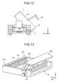
FIG. 12 is a schematic diagram illustrating an exemplary state in which thevessel 7 is lifted up by theside dump mechanism 19. As illustrated inFIG. 11 , theside dump mechanism 19 tilts thevessel 7 around a shaft J parallel to the Y-axis. In short, in the present embodiment, thetransport machine 1 discharges the load from thevessel 7 using a side-dump system. In the present embodiment, thevessel 7 includes a vesselmain body 24, and aside gate 25, which is pivotable with respect to the vesselmain body 24. Theside gate 25 pivots in synchronization with tilting (rising) movement of the vesselmain body 24. With this operation, anopening 7K is formed between the vesselmain body 24 and theside gate 25. The load of thevessel 7 is discharged to a side of thetransport machine 1 through theopening 7K. Note that the state that the rotation shaft of thevessel 7, namely, the shaft J, and the Y-axis are parallel includes at least one of a state where the Y-axis and the shaft J are perfectly parallel, and a state where the Y-axis and the shaft J are substantially parallel. Alternatively, the shaft J may be non-parallel to the Y-axis. For example, an angle formed by the shaft J and the Y-axis may be one or more degrees and 45 or less degrees. - In the present embodiment, in a state where the
vessel 7 is not lifted up, thesupport device 17 is arranged below an upper end of thefront wheel 8 and an upper end of therear wheel 9. In other words, in a state where thetransport machine 1 is traveling along the drift DR, thesupport device 17 is arranged below the upper end of thefront wheel 8 and below the upper end of therear wheel 9. -
FIG. 13 is a schematic diagram illustrating an exemplaryside dump mechanism 19B. Theside dump mechanism 19B illustrated inFIG. 13 uses a side ejector system to discharge the load from thevessel 7B in the X-axis direction. InFIG. 13 , thevessel 7B includes a vesselmain body 24B, and aside gate 25B that is pivotable with respect to the vesselmain body 24B. Theside gate 25B is pivotably moved by the power of acylinder mechanism 251. Theside dump mechanism 19B includes aplate 191, and adriving device 192. Theplate 191 is arranged on the vesselmain body 24B. Thedriving device 192 moves theplate 191 in the X-axis direction. Thedriving device 192 includes a multi-stage cylinder mechanism arranged between the vesselmain body 24B and theplate 191. When the load of thevessel 7 is discharged, theside gate 25B is raised by thecylinder mechanism 251. With this operation, anopening 7K is formed between the vesselmain body 24B and theside gate 25B. In a state where theopening 7K is formed, the drivingdevice 192 moves theplate 191 in the X-axis direction (-X direction in the example ofFIG. 13 ). The load of thevessel 7B is discharged to a side of thetransport machine 1 through theopening 7K. - Next, traveling of the
transport machine 1 will be described. In the present embodiment, thetransport machine 1 is an unmanned vehicle, which is an autonomous traveling vehicle capable of traveling autonomously.FIG. 14 is a functional block diagram including adetection system 60 of thetransport machine 1. - As illustrated in
FIG. 14 , thetransport machine 1 includes aprocessing device 51, astorage device 52, acommunication device 53, and thedetection system 60. Thedetection system 60 includes arange sensor 61, anon-contact sensor 62, a weight sensor 63, animaging device 64, areading device 65, aspeed sensor 66, anacceleration sensor 67, and asteering sensor 68. Therange sensor 61 outputs physical shape data of a space. Thenon-contact sensor 62 detects an obstacle. The weight sensor 63 detect the weight of thevessel 7. Theimaging device 64 can obtain an optical image of an object and detect the form of the object. Thereading device 65 detects a mark M (refer toFIG. 14 ) provided on the drift DR. Thespeed sensor 66 detects a traveling speed of thetransport machine 1. Theacceleration sensor 67 detects acceleration or an angular speed of thetransport machine 1. Thesteering sensor 68 detects at least one of steering angles of thefront wheel 8 and therear wheel 9. - The
processing device 51 includes a central processing unit (CPU). Theprocessing device 51, based on a result of detection by thedetection system 60, controls the travelingdevice 5 such that thetransport machine 1 moves to a predetermined target position. Theprocessing device 51 controls the travelingdevice 5 to travel along a predetermined route (target route) CS at a predetermined speed and acceleration by controlling the electric motor 16 (driving device) and a braking system of the travelingdevice 5, as well as controlling the steering angle of at least one of thefront wheel 8 and therear wheel 9. - The
storage device 52 includes at least one of random access memory (RAM), read only memory (ROM), flash memory, and a hard disk drive, and is connected with theprocessing device 51. Thestorage device 52 stores various types of information required for autonomous traveling. - The
communication device 53 is connected with theprocessing device 51 and performs data communication with one or both of theloading machine 2 and themanagement facility 3. Themanagement facility 3 communicates with thecommunication device 53 of thetransport machine 1 via the communication system 4. Thecommunication device 53 wirelessly communicates with themanagement facility 3 via therepeater 4A arranged inside the underground mine. Thecommunication device 53 can perform data communication with a communication device provided on theloading machine 2. Thecommunication device 53 can receive information (including a command signal) transmitted from at least one of themanagement facility 3 and theloading machine 2. Thecommunication device 53 can transmit information detected at thedetection system 60 to at least one of themanagement facility 3 and theloading machine 2. - The
range sensor 61 includes a scanning electro-optical distance measuring instrument capable of outputting physical shape data of a space. Therange sensor 61 includes at least one of a laser scanner and a three-dimensional distance sensor, and is capable of obtaining three-dimensional spatial data. Therange sensor 61 detects at least one of theloading machine 2 and a wall surface of the drift DR. In the present embodiment, therange sensor 61 can obtain at least one of shape data of theloading machine 2, shape data of a wall surface of the drift DR, and shape data of the load on thevessel 7. Therange sensor 61 can detect at least one of a relative position with respect to the loading machine 2 (relative distance and orientation) and a relative position with respect to the wall surface of the drift DR. In other words, therange sensor 61 can function as at least one of a load detection device (form detection device), a loading machine detection device (first detection device), and a second detection device. The load detection device detects a state of load (form of load) on thevessel 7. The loading machine detection device detects theloading machine 2. The second detection device detects the drift DR (tunnel R). Therange sensor 61 is connected with theprocessing device 51 and outputs a result of detection to theprocessing device 51. Therange sensor 61 may include radar. - In the present embodiment, information regarding the wall surface of the drift DR has been predetermined and stored in the
storage device 52. That is, the information regarding the wall surface of the drift DR is known information measured beforehand. The information regarding the wall surface of the drift DR includes information regarding each shape of a plurality of portions of the wall surface and information regarding an absolute position of each portions of the wall surface. Thestorage device 52 stores shape of a plurality of portions of the wall surface and a relationship between the shape and the absolute position of the portions of the wall surface having that shape. Theprocessing device 51 can obtain the absolute position and orientation of thetransport machine 1 in the drift DR based on a result of detection on the wall surface of the drift DR (shape data of wall surface) detected by therange sensor 61 provided on thetransport machine 1 and based on information stored in thestorage device 52. In this manner, therange sensor 61 can also function as a position detection device that detects a position of thetransport machine 1 that travels along the drift CR (tunnel R). - The
processing device 51 can control the travelingdevice 5 in the drift DR such that thetransport machine 1 can travel according to the predetermined route CS based on a current position (absolute position) of thetransport machine 1 measured by therange sensor 61. - The
non-contact sensor 62 detect an obstacle in front of thetransport machine 1. Thenon-contact sensor 62 includes radar. By emitting at least one of radio waves and ultrasonic waves, and receiving the radio waves reflected on the obstacle, thenon-contact sensor 62 can detect a distance and orientation relative to the obstacle. Thenon-contact sensor 62 may include at least one of a laser scanner and a three-dimensional distance sensor. Thenon-contact sensor 62 is connected with theprocessing device 51 and outputs a result of detection to theprocessing device 51. - The weight sensor 63 detects a weight of the
vessel 7. The weight sensor 63 can detect the weight of thevessel 7 and a weight of a load loaded onto thevessel 7. That is, the weight sensor 63 can function as a load detection device (weight detection device) that detects a state of the load on the vessel 7 (weight of the vessel 7). The weight sensor 63 is connected with theprocessing device 51 and outputs a result of detection to theprocessing device 51. Theprocessing device 51, based on the result of detection by the weight sensor 63, obtains information regarding the weight of the load loaded onto thevessel 7, and presence/absence of load on thevessel 7. The weight sensor 63 may include a strain gage based load cell provided, for example, between the slide table 20 and thevessel 7, and may include a pressure sensor that detects hydraulic pressure of the hoistcylinder 23. - The
imaging device 64 includes an imaging element such as a CCD, and can obtain an optical image of an object and detect a form of the object. In the present embodiment, theimaging device 64 includes a stereo camera and can obtain three-dimensional form data of the object. Theimaging device 64 can detect a form (appearance of load) of the load of thevessel 7. That is, theimaging device 64 can function as a load detection device (form detection device) to detect a state of the load of the vessel 7 (form of load). Theimaging device 64 is connected with theprocessing device 51 and outputs a result of detection to theprocessing device 51. Theprocessing device 51, based on a result of detection by theimaging device 64, obtains information regarding a state of the load on thevessel 7. The form of the load on thevessel 7 may be detected by using at least one of a laser scanner and a three-dimensional distance sensor. - The
reading device 65 detects the mark M provided on the drift DR. The mark M is arranged in plurality along with the drift DR. The mark M may be an identifier (code) such as a bar code and a two-dimensional code, or may be an identifier (tag) such as an IC tag and an RFID. Thereading device 65 detects identification information or specific information of the mark M. Thereading device 65 is connected with theprocessing device 51 and outputs a result of detection to theprocessing device 51. - In the present embodiment, the information regarding the position of the mark M (absolute position) in the drift DR is known information measured beforehand. Information regarding the absolute position of the mark M is stored in the
storage device 52. Theprocessing device 51 can obtain the absolute position of thetransport machine 1 in the drift DR based on the result of detection on the mark M detected by thereading device 65 provided on thetransport machine 1, namely, identification information or specific information on the mark M and based on stored information in thestorage device 52. That is, thereading device 65 can also function as a position detection device that detects the position of thetransport machine 1 that travels along the drift DR (tunnel R). Thereading device 65 also functions as the second detection device to detect the mark M provided on the drift DR (tunnel R). - The
processing device 51 can control the travelingdevice 5 in the drift DR such that thetransport machine 1 can travel according to the predetermined route CS based on a current position (absolute position) of thetransport machine 1 obtained by thereading device 65. - The mark M may be a structure such as a landmark. In a case where the mark M is a landmark, the
reading device 65 may include radar. Thereading device 65 emits radio waves from radar and receives at least a portion of the emitted radio waves reflected on the landmark, thereby making it possible to detect a relative distance and orientation with respect to the landmark. In a case where a position (absolute position) at which the landmark is arranged is known and information regarding the absolute position of the landmark has been stored in thestorage device 52, theprocessing device 51 can obtain the absolute position of thetransport machine 1 in the drift DR based on the detected value on thereading device 65 provided on thetransport machine 1 and based on the information stored in thestorage device 52. - Each of the
speed sensor 66, theacceleration sensor 67, and thesteering sensor 68 is connected with theprocessing device 51. Thespeed sensor 66 outputs a detection value of the traveling speed of thetransport machine 1 onto theprocessing device 51. Theacceleration sensor 67 outputs the detection value of the acceleration of thetransport machine 1 onto theprocessing device 51. Thesteering sensor 68 outputs a detection value of the steering angle of at least one of thefront wheel 8 and therear wheel 9 onto theprocessing device 51. - In the present embodiment, the
processing device 51, based on, for example, the detection values of thespeed sensor 66 and thesteering sensor 68, allows the travelingdevice 5 to travel according to dead reckoning navigation. In other words, theprocessing device 51 estimates a current position of thetransport machine 1 using dead reckoning navigation, and controls the travelingdevice 5 in the drift DR such that thetransport machine 1 travels according to the predetermined route CS. - Dead reckoning navigation is a navigation system of estimating a current position of an object (transport machine 1) based on orientation (orientation variation) and a moving distance from a reference position (origin) for which the absolute position is known. Orientation of the
transport machine 1 is detected with thesteering sensor 68 arranged on thetransport machine 1. The moving distance of thetransport machine 1 is detected by using thespeed sensor 66 arranged on thetransport machine 1. A detection value of thesteering sensor 68 and a detection value of thespeed sensor 66 are output onto theprocessing device 51 of thetransport machine 1. Theprocessing device 51 can obtain orientation of thetransport machine 1 from a known reference position bases on the detection value of thesteering sensor 68. Theprocessing device 51 can obtain a moving distance of thetransport machine 1 from the known reference position based on the detection value of thespeed sensor 66. In this manner, thedetection system 60 including thesteering sensor 68 and thespeed sensor 66 can detect the relative position of thetransport machine 1 with respect to the reference position based on dead reckoning navigation. In other words, in the present embodiment, thespeed sensor 66 and thesteering sensor 68 function as relative position detection devices to detect the relative position with respect to the reference position based on dead reckoning navigation. Theprocessing device 51, based on the detection value of thesteering sensor 68 and the detection value of thespeed sensor 66, controls the travelingdevice 5 such that thetransport machine 1 travels according to the predetermined route CS. Alternatively, orientation (orientation variation) of thetransport machine 1 may be detected by a gyro sensor arranged on thetransport machine 1. - After the relative position of the
transport machine 1 with respect to the reference position has been detected with dead reckoning navigation, theprocessing device 51 may correct the result of detection based on information regarding the absolute position of thetransport machine 1 in the drift DR obtained by using one or both of the result of detection by therange sensor 61 and the result of detection by thereading device 65. Specifically, in a case where the traveling distance of thetransport machine 1 is increased, detection errors of one or both of thesteering sensor 68 and thespeed sensor 66 have been accumulated. Accordingly, an error might occur between the position that has been estimated (estimated position) and the actual position. This might cause thetransport machine 1 to deviate from the route CS during traveling. In the present embodiment, the configuration may be such that theprocessing device 51 controls the travelingdevice 5 while correcting the position of thetransport machine 1 that has been derived (estimated) with dead reckoning navigation, by using information regarding the absolute position of thetransport machine 1 obtained from the results of detection by at least one of therange sensor 61 and thereading device 65. Theprocessing device 51, based on a detection value of thesteering sensor 68, a detection value of thespeed sensor 66, and information regarding the absolute position of thetransport machine 1, calculates a control amount regarding traveling of thetransport machine 1, including a correction amount of the position of thetransport machine 1, such that thetransport machine 1 travels according to the route CS. Theprocessing device 51, based on the calculated correction amount and control amount, controls the travelingdevice 5 such that thetransport machine 1 travels according to the route CS. -
FIG. 15 is a schematic diagram illustrating anexemplary detection system 60 mounted on thetransport machine 1. As illustrated inFIG. 15 , the imaging device (load detection device, form detection device) 64 is supported by thevehicle body 6 via asupport device 69. Theimaging device 64 is arranged at a position where the form of the load on thevessel 7 is detectable. Note that as described above, in place of theimaging device 64, or together with theimaging device 64, therange sensor 61 including at least one of a laser scanner and a three-dimensional distance sensor can be used to detect the form of the load on thevessel 7. That is, therange sensor 61 may be supported by thesupport device 69. - The
imaging device 64 may be arranged at a predetermine position on thevehicle body 6, where an optical image of theloading machine 2 is obtainable. Alternatively, theimaging device 64 may be arranged at a predetermined position on thevehicle body 6, where an optical image of the wall surface of the drift DR (three-dimensional form data) is obtainable. In this case, theimaging device 64 functions as at least one of a loading machine detection device (first detection device) that detects theloading machine 2 and a second loading machine that detects the drift DR (tunnel R). -
FIG. 16 is a schematic diagram illustrating anexemplary detection system 60 mounted on thetransport machine 1. As illustrated inFIG. 16 , thenon-contact sensor 62 to detect an obstacle may be arranged at one or both of thefront surface 31 and therear surface 41, of thevehicle body 6. - A range sensor (second detection device, position detection device, loading machine detection device, and first detection device) 61 that can detect at least one of shape data of the
loading machine 2, shape data of a wall surface of the drift DR, the relative position with respect to theloading machine 2, and the relative position with respect to the wall surface of the drift DR is arranged at a predetermined position of thevehicle body 6. As an example illustrated inFIG. 16 , therange sensor 61 is arranged on a side surface of thevehicle body 6 such that at least one of the shape data of the wall surface of the drift DR, and the relative position with respect to the wall surface of the drift DR is detectable. Therange sensor 61 may be arranged at least on a portion of the top surface, the side surface, the front surface, and the rear surface, of thevehicle body 6, such that at least one of the shape data of theloading machine 2, and the relative position of theloading machine 2 is detectable. - The reading device (position detection device, second detection device) 65 is arranged at a predetermined position of the
vehicle body 6, such as a side surface of thevehicle body 6, such that the mark M arranged on the wall surface of the drift DR is detectable. - Next, a
management device 80 arranged in themanagement facility 3 will be described.FIG. 17 is a block diagram illustrating anexemplary management device 80 according to the present embodiment. As illustrated inFIG. 17 , themanagement device 80 includes acomputer system 81, adisplay device 85, aninput device 86, and acommunication device 87. - The
computer system 81 includes aprocessing device 82, astorage device 83, and an input/output unit 84. Each of thedisplay device 85, theinput device 86, and thecommunication device 87 is connected with thecomputer system 81 via the input/output unit 84. The input/output unit 84 is served for input/output (interface) of information with at least one of theprocessing device 82, thedisplay device 85, theinput device 86, and thecommunication device 87. - The
processing device 82 includes a central processing unit (CPU) and executes various types of processing regarding control of mining machines including thetransport machine 1 and theloading machine 2. Theprocessing device 82 processes information regarding the position of thetransport machine 1 obtained via the communication system 4. Theprocessing device 82 generates the route CS on which thetransport machine 1 travels. The route CS is generated on an absolute position coordinate system. Thetransport machine 1 travels at least on a portion of the tunnel R according to the route CS generated by theprocessing device 82. - The
storage device 83 includes at least one of random access memory (RAM), read only memory (ROM), flash memory, and a hard disk drive, and stores various types of information regarding control of mining machines. Thedisplay device 85 includes, for example, a flat panel display such as a liquid crystal display and can display information regarding a position of the mining machine. Theinput device 86 includes at least one of a keyboard, a touch panel, a mouse, and an operation switch. When operated, theinput device 86 generates an operation signal and inputs it to theprocessing device 82. - The communication system 4 includes the
communication device 87 arranged in themanagement facility 3. Thecommunication device 87 is connected with therepeater 4A by a wired connection. Theprocessing device 82 can transmit various types of information such as information regarding the route CS from thecommunication device 87 to thetransport machine 1. At least one of positional information of thetransport machine 1 and information regarding the state of the load detected by thedetection system 60 is received via thecommunication device 87 and stored in thestorage device 83. - Next, exemplary operation of the
transport machine 1 will be described with reference toFIG. 18. FIG. 18 is a flowchart illustrating exemplary operation of thetransport machine 1 according to the present embodiment. Thetransport machine 1 with no load (empty load state) travels along the drift DR toward the loading position LP in order to pick the load (step SP1). During traveling along the drift DR, the center of thevessel 7 and the center of thevehicle body 6 overlap with each other with respect to the X-axis direction. Accordingly, thevessel 7 is not lifted up. Information regarding the route CS is transmitted from themanagement device 80 to thetransport machine 1 via the communication system 4. The transmitted information is stored in thestorage device 52 of thetransport machine 1. The route CS is a route based on the absolute position. Theprocessing device 51 of thetransport machine 1 controls the travelingdevice 5 such that thetransport machine 1 travels along the drift DR according to the route CS generated by themanagement device 80. Thetransport machine 1 autonomously travels along the drift DR toward the loading position LP such that thevessel 7 is arranged at the loading position LP, namely, the target position. - As described above, the
processing device 51 can derive an absolute position of thetransport machine 1 on the drift DR based on at least one of the result of detection by therange sensor 61 and the result of detection by thereading device 65, and based on the storage information of thestorage device 52 Theprocessing device 51 controls the travelingdevice 5 such that thetransport machine 1 travels along the drift DR according to the route CS toward the loading position LP. Theprocessing device 51 controls the travelingdevice 5 in the drift DR toward the loading position LP such that thevessel 7 is arranged at the loading position LP based on at least one of the result of detection by therange sensor 61 and the result of detection by thereading device 65. - The
range sensor 61 can detect the relative position with respect to the wall surface of the drift DR. Theprocessing device 51, based on the result of detection by therange sensor 61, controls the travelingdevice 5 such that thetransport machine 1 travels along the wall surface of the drift DR. Theprocessing device 51 controls the travelingdevice 5, for example, to prevent thetransport machine 1 from contacting the wall surface of the drift DR during traveling on the drift DR. - Note that, in the drift DR, the
transport machine 1 may contact the wall surface of the drift DR. For example, in a case where the width of the drift DR (road width) is small, or thetransport machine 1 turns a corner of the drift DR, thetransport machine 1 may travel while contacting the wall surface of the drift DR. Alternatively, a guide member (e.g. guide rail) may be provided at a corner of the drift DR and a guided portion (e.g. roller) to be guided by the guide member may be provided on thetransport machine 1. With this configuration, it is possible to allow thetransport machine 1 to turn the corner of the drift DR while allowing the guided portion to contact the guide member. - In the present embodiment, the
transport machine 1 moves along the drift DR in the +Y0 direction to enter the loading position LP. After thetransport machine 1 reaches the vicinity of the loading position LP, theprocessing device 51 controls the travelingdevice 5 to stop thetransport machine 1. After thetransport machine 1 reaches the vicinity of the loading position LP, theprocessing device 51 detects theloading machine 2 by using the range sensor 61 (step SP2). Theprocessing device 51 obtains form data of theloading machine 2 by using therange sensor 61, and at the same time, detects the relative positions of thetransport machine 1 and theloading machine 2. Theprocessing device 51, based on the result of detection by therange sensor 61, controls the position of thevessel 7 such that thevessel 7 is arranged at the loading position LP of theloading machine 2. - By obtaining the form data of the
loading machine 2 and detecting the relative position with respect to theloading machine 2, it is possible for theprocessing device 51 to arrange thevessel 7 to a position suitable for loading operation. Theprocessing device 51, based on the result of detection by therange sensor 61, arranges thevessel 7 at the loading position LP so as to prevent thetransport machine 1 including thevessel 7 and theloading machine 2 from coming in contact with each other. -
FIG. 19 is a perspective view of an exemplary state in which a load is being loaded onto thevessel 7 by theloading machine 2.FIG. 20 is a side view. InFIGS. 19 and 20 , theloading machine 2 includes anundercarriage 90, afeeder device 91, a draw-indevice 92, and a penetratingmember 93. Theundercarriage 90 includes a crawler. Thefeeder device 91 is supported by theundercarriage 90 and can supply a load, namely, ore, to thevessel 7. The draw-indevice 92 draws the load into thefeeder device 91. The penetratingmember 93 penetrates into a mine. - The
feeder device 91 includes a tilted conveyer. Thefeeder device 91 moves the load from a front section to a rear section of thefeeder device 91. In the present embodiment, the front section of thefeeder device 91 is arranged below the rear section of thefeeder device 91. The load drawn into the front section (lower portion) of thefeeder device 91 is raised by thefeeder device 91 and supplied to thevessel 7 from the rear section (supply unit, upper portion) of thefeeder device 91. In the present embodiment, the loading position LP includes a position below the supply unit of thefeeder device 91. - In the present embodiment, based on the result of detection by the
range sensor 61, the travelingdevice 5 is controlled to prevent thetransport machine 1 and theloading machine 2 from coming in contact with each other, and at the same time, at least a portion of thetransport machine 1 enters below the supply unit of thefeeder device 91. In the present embodiment, when thevessel 7 enters the loading position LP, theupper surface 34A and theupper surface 44A, which are arranged near thefeeder device 91, are arranged in a low position. Accordingly, it is possible to suppress contact of thefeeder device 91 and thevehicle body 6. - As illustrated in
FIGS. 19 and 20 , theprocessing device 51 adjusts the position of thevessel 7 such that thevessel 7 is arranged below the supply unit of the feeder device 91 (step SP3). In the present embodiment, thevessel 7 is moved by theslide mechanism 18 such that, when the load is loaded onto thevessel 7, at least a portion of thevessel 7 is arranged outside thevehicle body 6. In the present embodiment, with respect to thetransport machine 1 that moves along the drift DR in the +Y0 direction, theloading machine 2 is arranged on the +X side. Theprocessing device 51 detects relative positions of thetransport machine 1 and theloading machine 2 by using therange sensor 61. Based on the result of detection, theprocessing device 51 controls theslide mechanism 18 such that thevessel 7 is arranged below the supply unit of thefeeder device 91 arranged on the +X side. Theprocessing device 51 controls theslide mechanism 18 based on the result of detection by therange sensor 61 so as to move thevessel 7 in the +X direction and adjust the position of thevessel 7 with respect to theloading machine 2. In the present embodiment, theprocessing device 51, in a state where the position of thevehicle body 6 is fixed, moves thevessel 7 by using theslide mechanism 18 so as to arrange thevessel 7 at the loading position LP. - Note that in a case where the
processing device 51 adjusts the position of thevessel 7 such that thevessel 7 is arranged at the loading position LP, theprocessing device 51 may adjust the position of thevessel 7 by controlling the travelingdevice 5 to move thevehicle body 6. Alternatively, in order to arrange thevessel 7 at an optimum position, theprocessing device 51 may control both the travelingdevice 5 and theslide mechanism 18 to move thevehicle body 6 with respect to the road surface, and at the same time, may move thevessel 7 with respect to thevehicle body 6. - In a state where the
vessel 7 is arranged at an optimum position with respect to thefeeder device 91, a load is supplied from thefeeder device 91 to thevessel 7. With this operation, the load is loaded from theloading machine 2 to the vessel 7 (step SP4). The position of thevessel 7 is adjusted, and thus, it is possible to suppress the load leakage (load dropping). -
FIG. 21 is a schematic diagram illustrating an exemplary state where the load is loaded from thefeeder device 91 onto thevessel 7. As illustrated inFIG. 21 , it might be possible that the ore supplied from thefeeder device 91 is piled on a portion of thevessel 7, causing an uneven load on thevessel 7. As described with reference toFIGS. 14 and 15 , in the present embodiment, thetransport machine 1 includes theimaging device 64 capable of detecting a state of the load of thevessel 7. In the present embodiment, based on the result of detection by theimaging device 64, theprocessing device 51 can control theslide mechanism 18 to adjust the position of thevessel 7. Theimaging device 64 can detect the form of the load on thevessel 7. When theprocessing device 51 determines that the load is going to be piled unevenly on thevessel 7 based on the result of detection by theimaging device 64, theprocessing device 51 adjusts the position of thevessel 7 with respect to thefeeder device 91 of theloading machine 2 by moving thevessel 7 in the X-axis direction so as to reduce the degree of unevenness. As in an example illustrated inFIG. 21 , the load is piled unevenly on an - X-side end of thevessel 7. Theprocessing device 51 moves thevessel 7 in the -X direction so as to improve the uneven load. With this configuration, the load is supplied from thefeeder device 91 to a +X-side end of thevessel 7, making it possible to suppress the uneven load on thevessel 7. - Based on the result of detection by the weight sensor 63 capable of detecting the weight of the
vessel 7, the position of thevessel 7 with respect to theloading machine 2 may be adjusted by moving thevessel 7 in the X-axis direction with theslide mechanism 19. For example, thevessel 7 may be moved by a predetermined distance in the X-axis direction each time the weight sensor 63 detects an increase in the predetermined weight. When the relationship between the weight of thevessel 7 and the form of the load (appearance of load) that corresponds to the weight is known, theprocessing device 51 may move thevessel 7, based on the result of detection by the weight sensor 63, so as to adjust the appearance of the load to be an appropriate shape. - Note that, for example, in a case where the weight sensor 63 capable of detecting the weight of the
vessel 7 can detect the state of the load of thevessel 7, thevessel 7 may be moved in the X-axis direction by theslide mechanism 18 based on the result of detection by the weight sensor 63. For example, in a case where the weight sensor 63 can detect uneven loading on thevessel 7 due to an uneven load, theprocessing device 51 may move thevessel 7 in the X-axis direction so as to improve the unevenness. - The
processing device 51 may control theslide mechanism 18 so as to reciprocate (rock) thevessel 7 with respect to the X-axis direction. In a case, for example, where the load is piled unevenly on thevessel 7, or piled up too high on thevessel 7, it is possible to level the load by reciprocating thevessel 7. By leveling the load, it is possible to achieve a higher full-capacity rate of the load on thevessel 7. - The
processing device 51 may determine amplitude of reciprocation of thevessel 7 based on the result of detection by theimaging device 64. For example, in a case where it is determined that the load is piled up too high, based on the result of detection by theimage device 64, theprocessing device 51 may reciprocate thevessel 7 with greater amplitude. In a case where it is determined that the load is piled up in a plurality of locations, based on the result of detection by theimage device 64, theprocessing device 51 may reciprocate thevessel 7 with smaller amplitude. When increasing the amplitude, theprocessing device 51 may decrease the movement speed of thevessel 7. When decreasing the amplitude, theprocessing device 51 may increase the movement speed of thevessel 7. With this operation, it is possible to level the load efficiently. - The
processing device 51 may determine whether to reciprocate thevessel 7 or may determine one or both of amplitude and speed of reciprocation based on the result of detection by theimaging device 64 that detects the form of the load of thevessel 7 and based on the result of detection by the weight sensor 63 that detects the weight of thevessel 7. For example, in a case where it is determined that thevessel 7 is full of load based on the result of detection by theimaging device 64 and at the same time, it is determined that thevessel 7 is not yet full of load based on the result of detection by the weight sensor 63, it is estimated that there are numerous gaps between the ores loaded on thevessel 7. When theprocessing device 51 determines, based on the result of detection by theimaging device 64 and the result of detection by the weight sensor 63, that there are numerous gaps between the ores, theprocessing device 51 reciprocates thevessel 7 by controlling theslide mechanism 18. With this configuration, it is possible to reduce the gaps by leveling the load and increase the full-capacity rate. - Operation of reciprocating the
vessel 7 may be executed in parallel with at least part of operation of supplying the load from thefeeder device 91 to thevessel 7. In other words, theslide mechanism 18 may reciprocate thevessel 7 during a loading operation period in which the load is loaded onto thevessel 7. Note that the operation of reciprocating thevessel 7 may be executed after the load has been supplied from thefeeder device 91 to thevessel 7. In short, theslide mechanism 18 may reciprocate thevessel 7 during a period after completion of loading operation for thevessel 7. - After completion of the loading operation, the
transport machine 1 with load (in a loaded state) travels along the drift DR toward the ore path OP so as to discharge the load (step SP5). Thetransport machine 1 that has started from the loading position LP moves along the drift DR in the +Y0 direction. During traveling along the drift DR, the center of thevessel 7 and the center of thevehicle body 6 overlap with each other with respect to the X-axis direction. Accordingly, thevessel 7 is not lifted up. Theprocessing device 51 controls the travelingdevice 5 such that thetransport machine 1 travels along the drift DR according to the route CS generated by themanagement device 80. Thetransport machine 1 autonomously travels along the drift DR toward the ore path OP such that thevessel 7 is arranged at the ore path OP, namely, the target position. - In a period of moving toward the ore path OP, the
processing device 51 derives the absolute position of thetransport machine 1 at the drift DR based on the result of detection by at least one of therange sensor 61 and thereading device 65, and based on the information stored in thestorage device 52. Theprocessing device 51, then, controls the travelingdevice 5 such that thetransport machine 1 travels along the drift DR according to the route CS toward the ore path OP. Theprocessing device 51, based on at least one of the result of detection by therange sensor 61 and the result of detection by thereading device 65, controls the travelingdevice 5 at the drift DR toward the ore path OP such that thevessel 7 is arranged at the ore path OP. Theprocessing device 51, based on the result of detection by therange sensor 61, controls the travelingdevice 5 such that thetransport machine 1 travels along the drift DR. Theprocessing device 51 controls the travelingdevice 5, for example, to prevent thetransport machine 1 from contacting the wall surface of the drift DR during traveling along the drift DR. -
FIG. 22 is a diagram illustrating an exemplary state in which a load is being discharged from thevessel 7 at the ore path OP. After thetransport machine 1 reaches the ore path OP, theprocessing device 51 lifts up thevessel 7 by operating theside dump mechanism 19. With this operation, as illustrated inFIG. 22 , theside gate 25 pivots along with rising operation of thevessel 7, so as to form theopening 7K between the vesselmain body 24 and theside gate 25. The load on thevessel 7 is discharged from thevessel 7 via theopening 7K (step SP6). In an example illustrated inFIG. 22 , thevessel 7 is lifted up such that the load is discharged onto the -X side of thevehicle body 6. - When the load is discharged from the
vessel 7, theprocessing device 51 may operate theslide mechanism 18 so as to move thevessel 6 such that at least a portion of thevessel 7 is arranged outside thevehicle body 6. For example, theprocessing device 51 may move thevessel 7 in the -X direction by operating theslide mechanism 18, and thereafter, may lift up thevessel 7 by operating theside dump mechanism 19. Theprocessing device 51 may lift up thevessel 7 while moving thevessel 7 in the -X direction. - After completion of discharging operation of the load, the
transport machine 1 with no load starts traveling toward the loading position LP for loading operation. Thetransport machine 1 repeats the processing described hereinabove. - In the examples illustrated in
FIGS. 19 and 20 , the load is loaded from theloading machine 2 arranged at the crosscut CR on the +X side onto thetransport machine 1 that travels along the drift DR in the +Y0 direction. As described with reference toFIG. 3 , or the like, the load may be loaded onto thetransport machine 1 from theloading machine 2 arranged at the crosscut CR on the -X side with respect to thetransport machine 1. For example, theprocessing device 51 may detect relative positions of thetransport machine 1 and theloading machine 2, which is arranged on the -X side with respect to thetransport machine 1 by using therange sensor 61 such that thevessel 7 is arranged at the loading position LP arranged on the -X side with respect to thetransport machine 1 traveling along the drift DR in the +Y0 direction. Based on the result of detection, theprocessing device 51 may adjust the position of thevessel 7 with respect to theloading machine 2 by controlling theslide mechanism 18 to move thevessel 7 in the -X direction such that thevessel 7 is arranged below the supply unit of thefeeder device 91 of theloading machine 2. Also in this case, theupper surface 34B and theupper surface 44B, to be arranged near thefeeder device 91 when thevessel 7 enters the loading position LP, are arranged at low positions. Accordingly, it is possible to suppress a state where thefeeder device 91 and thevehicle body 6 come in contact with each other. In the present embodiment, thetransport machine 1 is left/right symmetrical. Accordingly, each of loading operation from the +X side and loading operation from the - X side is performed smoothly onto thetransport machine 1,. With this configuration, when the loading position LP is determined on any one side of the two, with respect to the moving direction of thetransport machine 1, loading operation is executed from the one determined side smoothly. - In the present embodiment, an example has been described in which the
transport machine 1 traveling along the drift DR in the +Y direction enters the loading position LP while moving in the +Y0 direction, thereafter, loading operation is performed onto thetransport machine 1, thereafter, thetransport machine 1 moves from the loading position LP in the +Y0 direction. Needless to say, thetransport machine 1 moving along the drift DR in the - Y0 direction may enter the loading position LP while moving in the -Y0 direction, thereafter, loading operation may be performed onto thetransport machine 1, thereafter, thetransport machine 1 may move from the loading position LP in the -Y0 direction. In a case where thetransport machine 1 moves in the -Y0 direction, therear section 6B may function as a front section and therear traveling device 5B may function as a front traveling device. In addition, the loading position LP at that time may be determined to be on the +X side or on the -X side of thetransport machine 1. In a case where the loading position LP is determined to be on the +X side, thevessel 7 may slide to the +X side. In a case where the loading position LP is determined to be on the -X side, thevessel 7 may slide to the -X side. Alternatively, thetransport machine 1 moving along the drift DR in the +Y0 (or -Y0) direction may enter the loading position LP while moving in the +Y0 (or -Y0) -Y0 direction, thereafter, loading operation may be performed onto thetransport machine 1, thereafter, thetransport machine 1 may move from the loading position LP in the - Y0 (or +Y1) direction. In short, the moving direction of thetransport machine 1 may be switched between a case of entering the loading position LP to execute loading operation and a case of starting from the loading position LP after executing the loading operation. In the present embodiment, thetransport machine 1 is front/rear symmetrical, and thus, can travel in any of +Y0 and -Y0 directions smoothly even when the moving direction is switched. - As described above, in the present embodiment, the
transport machine 1 includes thenon-contact sensor 62 that detects an obstacle. In a case where thenon-contact sensor 62 detects an obstacle existing on the drift DR when thetransport machine 1 is traveling along the drift DR, theprocessing device 51 outputs a result of detection by thenon-contact sensor 62 to themanagement device 80 of themanagement facility 3 via the communication system 4. Themanagement device 80 may create, for example, the route CS so as to avoid the obstacle. - In a case where the
non-contact sensor 62 detects an obstacle in front of thetransport machine 1, theprocessing device 51 may control the travelingdevice 5 to prevent thetransport machine 1 and the obstacle from coming in contact with each other. Specifically, theprocessing device 51 may cause thetransport machine 1 to stop traveling, to move reversely, or to travel while avoiding the obstacle. -
FIG. 23 is another example of thetransport machine 1. InFIG. 23 , thetransport machine 1 includes abumper 150 that clears an obstacle or a foreign substance on the road. In a case where thenon-contact sensor 62 detects an obstacle in front of thetransport machine 1, thetransport machine 1 may continue traveling while driving away the obstacle by using thebumper 150. - As described above, at least a portion of the
transport machine 1 operates on power supplied from thebattery 12.FIG. 24 illustrates an example in which thebattery 12 is released from the holdingsection 13 and the holdingsection 14. As illustrated inFIG. 24 , thebattery 12 is replaceable. On a portion of the drift DR, there is provided a replacement station EX (refer toFIG. 2 ) at which thebattery 12 is replaced. The holdingsection 13 and the holdingsection 14 removably hold thebattery 12. When a remaining capacity of thebattery 12 is lowered, thetransport machine 1 can move to the replacement station EX and replace thebattery 12. In the present embodiment, thebattery 12 is replaceable by sliding thebattery 12 in a front/rear direction with respect to therecess 37. A similar method is applicable to therecess 47. - In the present embodiment, the
device 12 that is removably held by the holdingsection 13 and the holdingsection 14 is a battery. Thedevice 12 is not limited to a battery. For example, an electronic device storing a program regarding traveling may be removably held by the holdingsection 13 and the holdingsection 14. In the present embodiment, the travelingdevice 5 operates on electric power. However, in a case where the travelingdevice 5 travels on a fuel, a container in which the fuel is contained may be removably held by the holdingsection 13 and the holdingsection 14. Thedevice 12, in any form as above, is replaceable at the replacement station EX. - In the above-described embodiment, an example has been described in which the
transport machine 1 autonomously travels by using thedetection system 60 including therange sensor 61 mounted on thetransport machine 1. For example, thetransport machine 1 may be controlled by using amanagement system 100 including adetection system 602 and adetection system 60D. Thedetection system 602 is arranged on theloading machine 2. Thedetection system 60D is arranged at the drift DR. -
FIG. 25 is a diagram illustrating anexemplary range sensor 612 of thedetection system 602 mounted on theloading machine 2, and anexemplary range sensor 61D of thedetection system 60D arranged in the tunnel R. For example, in the above-described embodiment, relative positions of thetransport machine 1 and theloading machine 2 are detected by therange sensor 61 arranged on thetransport machine 1. The relative positions of thetransport machine 1 and theloading machine 2 may be detected by the range sensor (position detection device) 612 provided on theloading machine 2. A result of detection on the relative positions may be transmitted from theloading machine 2 to thetransport machine 1, or may be transmitted from theloading machine 2 to thetransport machine 1 via themanagement device 80. Theprocessing device 51 of thetransport machine 1 may adjust the position of thevessel 7 such that thevessel 7 is arranged at the loading position LP of theloading machine 2, based on a result of detection by of therange sensor 612. Theprocessing device 51 may adjust the position of thevessel 7 by using theslide mechanism 18, or by using the travelingdevice 5. Alternatively, themanagement device 80, based on the result of detection by therange sensor 612, may transmit a command signal to thesupport device 17 and the travelingdevice 5 such that thevessel 7 is arranged at the loading position LP. In short, themanagement device 80 may remotely operate thetransport machine 1. - Meanwhile, the
range sensor 61D may be arranged at a predetermined position of one or both of the drift DR and the crosscut CR. When therange sensor 61D is arranged at a position where thetransport machine 1 and theloading machine 2 to be arranged at the loading position LP are detectable, it is possible to detect the relative positions of thetransport machine 1 and theloading machine 2. A result of detection by therange sensor 61D may be transmitted to thetransport machine 1 via themanagement device 80. - In the above-described embodiment, the relative positions of the
transport machine 1 and the wall surface of the drift DR, or the absolute position of thetransport machine 1, are detected by thedetection system 60 including therange sensor 61 and thereading device 65, arranged on thetransport machine 1. For example, the drift DR may be provided with a plurality of reading devices that can read identifiers arranged on thetransport machine 1. The absolute position of thetransport machine 1 may be obtained based on a result of detection by the reading device. In this case, the reading device functions as a position detection device that detects the position of thetransport machine 1 traveling on the drift DR (tunnel R). Moreover, there may be provided, on the drift DR, a plurality ofrange sensors 61D capable of detecting the relative position with respect to thetransport machine 1. The travelingdevice 5 of thetransport machine 1 may be controlled on the drift DR toward a target position (loading position LP, ore path OP, or the like) such that thevessel 7 of thetransport machine 1 is arranged at the target position, based on a result of detection by thedetection system 60D provided on the drift DR. The travelingdevice 5 may be controlled by themanagement device 80. Specifically, based on the result of detection by thedetection system 60D arranged on the drift DR, themanagement device 80 may transmit a command signal for moving thetransport machine 1 to the target position, and the travelingdevice 5 may travel based on the command signal. In short, themanagement device 80 may remotely operate thetransport machine 1. - Moreover, the imaging device (load detection device, form detection device) capable of detecting a state of the load on the
vessel 7 may be mounted on theloading machine 2 or arranged at a predetermined position on the drift DR. Based on a result of detection by the imaging device, the position of thevessel 7 may be adjusted, a slide movement amount of thevessel 7 may be adjusted, and thevessel 7 may be reciprocated in the X-axis direction. Meanwhile, loading conditions for theloading machine 2 may be controlled based on a state of load on thevessel 7, detected by using at least one of the imaging device arranged in thetransport machine 1, the imaging device arranged on theloading machine 2, and the imaging device arranged at a predetermined position of the drift DR. The loading conditions for theloading machine 2 include the amount of supply of load per a unit of time by the feeder device 91 (feeder speed), and the position of theloading machine 2 with respect to thevessel 7. - Alternatively, loading conditions for the
loading machine 2 may be controlled based on at least one of the result of detection by the imaging device, capable of detecting a state of the load of thevessel 7, arranged on at least one of thetransport machine 1, theloading machine 2, and the drift DR, and the result of detection by the weight sensor capable of detecting the weight of thevessel 7. In this case, loading conditions for theloading machine 2 include at least one of the feeder speed of thefeeder device 91 and a loading amount (total weight) of the load loaded onto thevessel 7 by theloading machine 2. - As described above, according to the present embodiment, the
transport machine 1 has a form and structure that are substantially front/rear symmetrical. Accordingly, thetransport machine 1 can smoothly travel in any of the directions of the +Y direction, namely, a forward direction of thefront section 6A, and the -Y direction, namely, a forward direction of therear section 6B. In a case where the transport machine is not front/rear symmetrical, for example, there is a possibility that, while the machine can travel in forward direction of the front section, the machine cannot travel smoothly in the forward direction of the rear section. If such a transport machine that is not front/rear symmetrical is going to change the moving direction during traveling in the +Y0 direction, for example, the transport machine might attempt, in the tunnel R, switchback operation (steering wheel operation to change direction) so as to change the moving direction of the front section to the -Y0 direction. Unfortunately, in many cases, however, there is a limitation in a size (width) of the tunnel R. Accordingly, such a switchback operation might be difficult. In the present embodiment, thetransport machine 1 is front/rear symmetrical. Therefore, it is possible to move smoothly in any direction without performing such switchback operation. - In the present embodiment, the
transport machine 1 is left/right symmetrical. With this configuration, even in a case where the loading position LP and a drawpoint DP are determined to be located on both sides (+X0 side and - X0 side) of the drift DR, loading operation is executable smoothly from both sides. - Meanwhile, in the present embodiment, the
vessel 7 is arranged between thefront traveling device 5A and therear traveling device 5B. Accordingly, it is possible to suppress an increase in the height of thetransport machine 1. In many cases, the size (height) of the tunnel R has limitation. In the present embodiment, the vehicle-height of thetransport machine 1 is suppressed. Accordingly, thetransport machine 1 can travel smoothly in a narrow tunnel R. - Meanwhile, in the present embodiment, the
front wheel 8 is driven by the frontwheel driving device 10, and therear wheel 9 is driven by the rearwheel driving device 11, that is, a whole-wheel-drive system is employed. Accordingly, the travelingdevice 5 can move smoothly in the tunnel R. In addition, the frontwheel driving device 10 and the rearwheel driving device 11, both of which including theelectric motor 16, are arranged at a front and rear of thetransport machine 1, respectively. This configuration makes it possible to suppress an increase in the vehicle-height of thetransport machine 1 and to arrange a high-power electric motor 16 (160). - In the present embodiment, the
support device 17 that supports thevessel 7 is arranged below the upper end of thefront wheel 8, and below the upper end of therear wheel 9. This configuration suppresses an increase in the height of thetransport machine 1. - Meanwhile, in the present embodiment, the
vessel 7 moves in the X-axis direction by theslide mechanism 18. With this configuration, it is possible, in the narrow tunnel R, to allow thevessel 7 to smoothly enter below thefeeder device 91, leading to smooth loading operation. In the tunnel R, which has a height limitation, it is probably difficult to arrange a portion of thevehicle body 6 together with thevessel 7 below thefeeder device 91. In the present embodiment, it is possible to slide thevessel 7, and arrange thevessel 7 alone below thefeeder device 91. With this configuration, it is possible to allow thefeeder device 91 to execute loading operation smoothly even in the narrow tunnel R. In the present embodiment, thevessel 7 is slidable to both the +X side and the -X side. Accordingly, it is possible to position thevessel 7 smoothly with respect to theloading machine 2 to be arranged on each of the +X side and -X side with respect to thetransport machine 1. - Meanwhile, in the present embodiment, the
support device 17 includes theside dump mechanism 19. Thetransport machine 1 discharges the load on thevessel 7 using a side-dump system. With this configuration, it is possible to suppress an increase in the height of thetransport machine 1. - In the present embodiment, regarding the X-axis direction, an upper surface (first upper surface) 34A and an upper surface (first upper surface) 34B of the
front section 6A are arranged below an upper surface (third upper surface) 12D of thebattery 12 being at a level between theupper surface 34A and theupper surface 34B. In addition, an upper surface (fourth upper surface) 44A and an upper surface (fifth upper surface) 44B of therear section 6B are arranged below anupper surface 12D of thebattery 12 being at a level between theupper surface 44A and theupper surface 44B. Therefore, for example, when thevessel 7 is arranged below thefeeder device 91, at least a portion of thevehicle body 6 is allowed to enter below the supply unit of thefeeder device 91 in a state where at least one of theupper surface 34A, theupper surface 34B, theupper surface 44A, and theupper surface 44B are arranged below the supply unit of thefeeder device 91. With this configuration, it is possible to arrange thevessel 7 below thefeeder device 91 while suppressing contact between thefeeder device 91 and thevehicle body 6. In the present embodiment, theupper surface 7A of thevessel 7 is arranged at a same level of theupper surface 34 and theupper surface 44 or below theupper surface 34 and theupper surface 44. With this configuration, it is possible arrange thevessel 7 below thefeeder device 91 while suppressing the contact between thefeeder device 91 and thevehicle body 6. - Moreover, by positioning the
upper surface 34 and theupper surface 44 at a low level, thedevice 12 that has not been arranged in thefront section 6A and therear section 6B due to capacity shortage can be arranged at a central portion with respect to the X-axis direction. As a result, thetransport machine 1 can travel while carrying thenecessary device 12. - In the present embodiment, the
device 12 is removably held by each of the holdingsection 13 and the holdingsection 14. With this configuration, thedevice 12 is smoothly replaceable. In a case where thedevice 12 is one of consumables such as a battery, or a renewable device such as a computer program or an electronic device, a configuration in which thedevice 12 is replaceable allows thetransport machine 1 to travel smoothly. - In the present embodiment, the configuration may be such that both the holding
section 13 and the holdingsection 14 removably hold thedevice 12; or any one of the holdingsection 13 and the holdingsection 14 removably holds thedevice 12 and the other one unremovably holds thedevice 12. - In the present embodiment, a protection member (battery cover) to protect the
battery 12 may be arranged so as to cover theupper surface 34A, theupper surface 12D of thebattery 12, and theupper surface 34B. In addition, a bracket for attaching various types of sensors for thedetection system 60 may be arranged. In this case, the protection member or the bracket may have a first upper surface of thefront section 6A that includes an end of thefront section 6A regarding the X-axis direction, a second upper surface of thefront section 6B that includes the other end of thefront section 6A, and a third upper surface arranged between the first upper surface and the second upper surface, above the first upper surface and the second upper surface. In other words, the first surface and the second upper surfaces may be arranged on a member that is separate from thevehicle body 6. Alternatively, a member including the first upper surface and the second upper surface may be regarded as a portion of the vehicle body 6 (front section 6A). A similar arrangement is applicable to therear section 6B. - In the present embodiment, a structure that is different from the
vessel 7 may be attached on thevessel 7.FIG. 26 illustrates an example in which, as a member that is different from thevessel 7, a protection member (battery guard) 170 that protects thebattery 12 is attached on thevessel 7. Theprotection member 170 is a member, for example, that prevents the load (ore) from hitting thebattery 12 in loading operation of the load onto thevessel 7. As illustrated inFIG. 26 , theprotection member 170 is arranged above theupper surface 7A of thevessel 7, theupper surface 34 of thefront section 6A, theupper surface 44 of therear section 6B, and theupper surface 12D of thebattery 12. InFIG. 26 , theupper surface 7A of thevessel 7 may be arranged below or above theupper surface 34 and theupper surface 44, or within a same plane as theupper surface 34 and theupper surface 44. In an example illustrated inFIG. 26 , theprotection member 170 is a structure different from thevessel 7, but may be regarded as a portion of thevessel 7. In this case, the upper surface of thevessel 7 is arranged above theupper surface 34, theupper surface 44, and theupper surface 12D. - In the present embodiment, the upper surface 34 (
upper surface 34A andupper surface 34B) is arranged on the vehicle body 6 (front section 6A), and theupper surface 12D arranged between theupper surface 34A and theupper surface 34B is arranged on thedevice 12, separate from thevehicle body 6. Thevehicle body 6 and thedevice 12 may be integrated with each other. That is, theupper surface 34 and theupper surface 12D may be an upper surface with a single member. A similar configuration is applicable to the upper surface 44 (upper surface 44A andupper surface 44B) and theupper surface 12D. - In the present embodiment, there is provided the
imaging device 64 that detects the form of the load (appearance of load) of thevessel 7. Accordingly, based on the result of detection by theimaging device 64, it is possible to adjust the position of thevessel 7 with respect to the supply unit of thefeeder device 91 and to reciprocate thevessel 7 so as to obtain a form of load in a desired shape. With this configuration, it is possible to suppress load collapse or load dropping and to transport the load in a state with the full-capacity rate of the load on thevessel 7 being high. - In the present embodiment, the
processing device 51 can travel autonomously based on the result of detection by thedetection system 60. Theprocessing device 51 can obtain the relative positions of thetransport machine 1 and theloading machine 2 based on the result of detection by the detection system 60 (range sensor 61, or the like). Accordingly, it is possible to arrange thevessel 7 at an optimum position with respect to theloading machine 2. Theprocessing device 51 can obtain the relative positions of thetransport machine 1 and the wall surface of the drift DR based on the result of detection by the detection system 60 (range sensor 61, or the like). Accordingly, it is possible to allow the travelingdevice 5 to travel while suppressing the contact with the drift DR. Theprocessing device 51 can obtain the absolute position of thetransport machine 1 based on the result of detection by the detection system 60 (reading device 65, or the like). Accordingly, it is possible to allow thetransport machine 1 to smoothly travel autonomously. - In the above-described embodiment, the
vessel 7 is provided separate from thevehicle body 6 and is movably supported by thevehicle body 6. Thevessel 7 and thevehicle body 6 may be integrally provided. - In the above-described embodiment, an operator may ride on the
transport machine 1. Thetransport machine 1 may be a manned vehicle that travels according to operation by the operator. - The constituents described in the embodiments include constituents that could be easily conceived by a person skilled in the art and constituents that are substantially identical or equivalent in scope. Moreover, it is possible to appropriately combine the constituents described in the embodiments. In some cases, a portion of the constituents is not utilized.
-
- 1
- TRANSPORT MACHINE
- 2
- LOADING MACHINE
- 3
- MANAGEMENT FACILITY
- 4
- COMMUNICATION SYSTEM
- 5
- TRAVELING DEVICE
- 5A
- FRONT TRAVELING DEVICE
- 5B
- REAR TRAVELING DEVICE
- 6
- VEHICLE BODY
- 6A
- FRONT SECTION
- 6B
- REAR SECTION
- 6C
- RECESS
- 6D
- INTERMEDIATE SECTION
- 7
- VESSEL
- 8
- FRONT WHEEL
- 9
- REAR WHEEL
- 10
- FRONT WHEEL DRIVING DEVICE
- 11
- REAR WHEEL DRIVING DEVICE
- 12
- DEVICE (BATTERY)
- 12D
- UPPER SURFACE
- 13
- HOLDING SECTION
- 14
- HOLDING SECTION
- 17
- SUPPORT DEVICE
- 18
- SLIDE MECHANISM
- 19
- SIDE DUMP MECHANISM
- 34
- UPPER SURFACE
- 34A
- UPPER SURFACE
- 34B
- UPPER SURFACE
- 44
- UPPER SURFACE
- 44A
- UPPER SURFACE
- 44B
- UPPER SURFACE
- 51
- PROCESSING DEVICE
- 52
- STORAGE DEVICE
- 53
- COMMUNICATION DEVICE
- 60
- DETECTION SYSTEM
- 61
- RANGE SENSOR
- 62
- NON-CONTACT SENSOR
- 63
- WEIGHT SENSOR
- 64
- IMAGING DEVICE
- 65
- READING DEVICE
- 66
- SPEED SENSOR
- 67
- ACCELERATION SENSOR
- 68
- STEERING SENSOR
- 80
- MANAGEMENT DEVICE
- 82
- PROCESSING DEVICE
- 100
- MANAGEMENT SYSTEM
- 602
- DETECTION SYSTEM
- 60D
- DETECTION SYSTEM
- AX
- CENTER
- CR
- CROSSCUT (SECOND TUNNEL)
- DP
- DRAWPOINT
- DR
- DRIFT (FIRST TUNNEL)
- LP
- LOADING POSITION
- M
- MARK
- OP
- ORE PATH (DUMPING POSITION)
- R
- TUNNEL
Claims (13)
- A transport machine comprising:a traveling device;a vehicle body arranged above the traveling device;a vessel provided on the vehicle body;a support device including a slide mechanism configured to move the vessel in a lateral direction with respect to the vehicle body, the lateral direction intersecting with a traveling direction of the traveling device when the transport machine travels straight; anda load detection device configure to detect a state of a load on the vessel,wherein the slide mechanism is controlled based on a result of detection by the load detection device.
- The transport machine according to claim 1,
wherein, in one or both of cases where the load is loaded onto the vessel and the load is discharged from the vessel, the slide mechanism is configured to move the vessel such that at least a portion of the vessel is arranged outside the vehicle body. - The transport machine according to claim 1 or 2,
wherein the slide mechanism is capable of moving the vessel such that at least a portion of the vessel is arranged on each of one and other sides of the vehicle body with respect to the lateral direction. - The transport machine according to any one of claims 1 to 3,
wherein the load detection device is configured to detect a form of a load of the vessel, and
based on a result of detection by the load detection device, the vessel is configured to move in the lateral direction by the slide mechanism such that a position of the vessel is adjusted with respect to a loading machine that loads a load onto the vessel. - The transport machine according to any one of claims 1 to 3,
wherein the load detection device is configured to detect a weight of the load of the vessel, and
based on a result of detection by the load detection device, the vessel is configured to move in the lateral direction by the slide mechanism such that a position of the vessel is adjusted with respect to a loading machine that loads a load onto the vessel. - The transport machine according to any one of claims 1 to 5, comprising:a loading machine detection device configured to detect a loading machine that loads a load onto the vessel,wherein, based on a result of detection by the loading machine detection device, the vessel is configured to move in the lateral direction by the slide mechanism such that a position of the vessel is adjusted with respect to the loading machine.
- The transport machine according to any one of claims 1 to 6,
wherein the slide mechanism is configured to reciprocate the vessel with respect to the lateral direction. - The transport machine according to claim 7,
wherein the slide mechanism is configured to reciprocate the vessel in one or both of a loading operation period in which a load is loaded on the vessel and a period after the loading operation period. - The transport machine according to claim 8, comprising:the load detection device configured to detect a state of a load of the vessel, andwherein an amplitude of reciprocation of the vessel is determined based on a result of detection by the load detection device.
- The transport machine according to claim 8, comprising:a form detection device configured to detect a form of a load of the vessel; anda weight detection device configured to detect a weight of the vessel,wherein whether to reciprocate the vessel is determined based on a result of detection by the form detection device and a result of detection by the weight detection device.
- The transport machine according to any one of claims 1 to 10, wherein the support device includes a side dump mechanism configured to discharge a load of the vessel to the lateral direction intersecting with the traveling direction.
- The transport machine according to any one of claims 1 to 9,
wherein the traveling device includes a front wheel and a rear wheel,
the vehicle body includes a recess arranged between the front wheel and the rear wheel, and
at least a portion of the vessel is arranged at the recess. - The transport machine according to claim 12,
wherein the vehicle body includes a front section, at least a portion of the front section being arranged above the front wheel,
the vehicle body includes a rear section, at least a portion of the rear section being arranged above the rear wheel,
the recess is arranged between the front section and the rear section, and
an upper surface of the vessel is arranged below an upper surface of the front section and an upper surface of the rear section.
Applications Claiming Priority (2)
| Application Number | Priority Date | Filing Date | Title |
|---|---|---|---|
| JP2013205913A JP6193075B2 (en) | 2013-09-30 | 2013-09-30 | Transport machine |
| PCT/JP2014/076209 WO2015046609A1 (en) | 2013-09-30 | 2014-09-30 | Transport machine |
Publications (3)
| Publication Number | Publication Date |
|---|---|
| EP3040237A1 true EP3040237A1 (en) | 2016-07-06 |
| EP3040237A4 EP3040237A4 (en) | 2017-07-12 |
| EP3040237B1 EP3040237B1 (en) | 2018-08-15 |
Family
ID=52743730
Family Applications (1)
| Application Number | Title | Priority Date | Filing Date |
|---|---|---|---|
| EP14848515.4A Not-in-force EP3040237B1 (en) | 2013-09-30 | 2014-09-30 | Underground transport machine |
Country Status (5)
| Country | Link |
|---|---|
| US (1) | US9873365B2 (en) |
| EP (1) | EP3040237B1 (en) |
| JP (1) | JP6193075B2 (en) |
| AU (1) | AU2014329319B2 (en) |
| WO (1) | WO2015046609A1 (en) |
Cited By (3)
| Publication number | Priority date | Publication date | Assignee | Title |
|---|---|---|---|---|
| KR20190123724A (en) * | 2017-03-10 | 2019-11-01 | 스미토모 겐키 가부시키가이샤 | Shovel |
| WO2022112166A1 (en) * | 2020-11-30 | 2022-06-02 | Autostore Technology AS | A remotely operated vehicle for handling a storage container on a rail system of an automated storage and retrieval system |
| EP4023822A4 (en) * | 2019-09-26 | 2022-11-23 | Kobelco Construction Machinery Co., Ltd. | Container measurement system |
Families Citing this family (10)
| Publication number | Priority date | Publication date | Assignee | Title |
|---|---|---|---|---|
| AU2017239926B2 (en) * | 2017-03-31 | 2018-11-15 | Komatsu Ltd. | Control system of transporter vehicle, transporter vehicle, and control method of transporter vehicle |
| CA3052235C (en) * | 2017-07-21 | 2021-10-26 | Komatsu Ltd. | Conveyance system, control apparatus, and conveyance method |
| JP7006322B2 (en) * | 2018-01-31 | 2022-01-24 | トヨタ自動車株式会社 | vehicle |
| US10831213B2 (en) | 2018-03-30 | 2020-11-10 | Deere & Company | Targeted loading assistance system |
| CN112740009A (en) * | 2018-09-21 | 2021-04-30 | 本田技研工业株式会社 | Vehicle inspection system |
| JP7165565B2 (en) | 2018-11-14 | 2022-11-04 | 株式会社小松製作所 | mining system |
| CH716412A2 (en) * | 2019-07-16 | 2021-01-29 | Rinspeed Ag | Vehicle configurator. |
| US11491904B1 (en) | 2019-12-23 | 2022-11-08 | Amity Technology, Llc | Material collection and transfer cart |
| JP7338561B2 (en) * | 2020-05-27 | 2023-09-05 | トヨタ車体株式会社 | Cabin mounting structure in a vehicle with upper and lower split structure |
| DE102021207174A1 (en) * | 2021-07-07 | 2023-01-12 | Hyundai Motor Company | Loading system and method for side loading and unloading of an upper body structure onto and from a vehicle platform of a motor vehicle |
Family Cites Families (23)
| Publication number | Priority date | Publication date | Assignee | Title |
|---|---|---|---|---|
| GB191016009A (en) | 1910-07-05 | 1911-03-09 | John Hood | New or Improved Double Traverse Side Tipping Wagon. |
| DE587100C (en) * | 1931-08-18 | 1933-11-02 | Tech Lab Tankred | Loading device for container traffic |
| US2477066A (en) * | 1947-04-28 | 1949-07-26 | Kuert | Hopper construction |
| US3054160A (en) * | 1961-03-17 | 1962-09-18 | Robert G Letourneau | Shuttle cars |
| FR2151147A5 (en) | 1971-08-20 | 1973-04-13 | Frangeco A N F | |
| US3809262A (en) * | 1971-10-15 | 1974-05-07 | A Galis | Self-propelled haulage vehicle |
| US3826387A (en) * | 1971-10-15 | 1974-07-30 | A Galis | Improved self-loading and self-propelled haulage vehicle |
| JPS5171509U (en) * | 1974-12-03 | 1976-06-05 | ||
| SE403092B (en) * | 1976-12-13 | 1978-07-31 | Lovgren Sten | DEVICES FOR CARRYING OUT OF LOAD UNITS TO AND FROM A FIRST CARRIER, INCLUDING A TRANSMISSION DEVICE FITNED TO ANOTHER CARRIER |
| DE2753720C2 (en) * | 1977-12-02 | 1984-10-18 | Lindemann Maschinenfabrik GmbH, 4000 Düsseldorf | Method and device for loading bales ejected from a horizontal baler |
| CH629446A5 (en) * | 1978-06-02 | 1982-04-30 | Sten Loevgren | Device for transferring transported goods |
| US4465155A (en) * | 1981-06-17 | 1984-08-14 | Collins Marshall S | Automated operatorless vehicles |
| US4537554A (en) * | 1983-01-14 | 1985-08-27 | The United States Of America As Represented By The Administrator Of The National Aeronautics And Space Administration | Shuttle car loading system |
| US4576107A (en) * | 1984-05-17 | 1986-03-18 | Atlantic Richfield Company | Apparatus for detecting the level of particulate solids in a shuttle car |
| JP2604641Y2 (en) * | 1992-05-29 | 2000-05-22 | ヤンマー農機株式会社 | Crop carrier |
| JPH07144570A (en) * | 1993-11-24 | 1995-06-06 | Furukawa Co Ltd | Pallet moving device for truck |
| FI115414B (en) | 2003-07-03 | 2005-04-29 | Sandvik Tamrock Oy | Arrangement for monitoring the location of a mine vehicle in a mine |
| US7438515B2 (en) * | 2003-09-16 | 2008-10-21 | Barry Leonard D | Container dump truck and oblique transfer system |
| US8100623B2 (en) * | 2009-08-07 | 2012-01-24 | Rogers Ralph R | Recycle container transfer vehicle |
| AU2011208154A1 (en) * | 2010-01-22 | 2012-07-19 | Hitachi Construction Machinery Co., Ltd. | Loading guide system |
| JP2013001362A (en) * | 2011-06-21 | 2013-01-07 | Komatsu Ltd | Truck |
| JP5852667B2 (en) * | 2011-10-17 | 2016-02-03 | 日立建機株式会社 | Dump truck stop position direction indication system and transport system |
| US10104824B2 (en) * | 2013-10-14 | 2018-10-23 | Kinze Manufacturing, Inc. | Autonomous systems, methods, and apparatus for AG based operations |
-
2013
- 2013-09-30 JP JP2013205913A patent/JP6193075B2/en active Active
-
2014
- 2014-09-30 AU AU2014329319A patent/AU2014329319B2/en not_active Ceased
- 2014-09-30 US US15/024,190 patent/US9873365B2/en not_active Expired - Fee Related
- 2014-09-30 WO PCT/JP2014/076209 patent/WO2015046609A1/en active Application Filing
- 2014-09-30 EP EP14848515.4A patent/EP3040237B1/en not_active Not-in-force
Cited By (6)
| Publication number | Priority date | Publication date | Assignee | Title |
|---|---|---|---|---|
| KR20190123724A (en) * | 2017-03-10 | 2019-11-01 | 스미토모 겐키 가부시키가이샤 | Shovel |
| EP3594414A4 (en) * | 2017-03-10 | 2020-04-15 | Sumitomo (S.H.I.) Construction Machinery Co., Ltd. | Shovel |
| KR102456137B1 (en) | 2017-03-10 | 2022-10-17 | 스미토모 겐키 가부시키가이샤 | shovel |
| US11619030B2 (en) | 2017-03-10 | 2023-04-04 | Sumitomo(S.H.I.) Construction Machinery Co., Ltd. | Shovel having boom raising assisting function using attachment information |
| EP4023822A4 (en) * | 2019-09-26 | 2022-11-23 | Kobelco Construction Machinery Co., Ltd. | Container measurement system |
| WO2022112166A1 (en) * | 2020-11-30 | 2022-06-02 | Autostore Technology AS | A remotely operated vehicle for handling a storage container on a rail system of an automated storage and retrieval system |
Also Published As
| Publication number | Publication date |
|---|---|
| EP3040237A4 (en) | 2017-07-12 |
| EP3040237B1 (en) | 2018-08-15 |
| US20160229326A1 (en) | 2016-08-11 |
| JP2015067242A (en) | 2015-04-13 |
| US9873365B2 (en) | 2018-01-23 |
| WO2015046609A1 (en) | 2015-04-02 |
| JP6193075B2 (en) | 2017-09-06 |
| AU2014329319B2 (en) | 2017-12-14 |
| AU2014329319A1 (en) | 2016-04-21 |
Similar Documents
| Publication | Publication Date | Title |
|---|---|---|
| EP3040237B1 (en) | Underground transport machine | |
| EP3040236B1 (en) | Transport machine and management system | |
| CN203700926U (en) | Motor-driven milling machine | |
| JP6416882B2 (en) | Mine management system | |
| US10800406B2 (en) | Mining machine, management system of mining machine, and management method of mining machine | |
| CN105467991B (en) | Stop position calculation device for transport vehicle and transport vehicle having the same | |
| CN107450554A (en) | A kind of submarine AGV and runtime | |
| CN112384661B (en) | Transport vehicle, system comprising a work machine for loading a transport vehicle with a raw material, method and work machine | |
| WO2015046610A1 (en) | Transporting machine | |
| WO2015046601A1 (en) | Ore extraction system | |
| WO2015046598A1 (en) | Transportation machine | |
| CN112469867A (en) | System and method for controlling a work machine for loading a transport vehicle with a raw material | |
| WO2015046608A1 (en) | Mine management system | |
| WO2015046599A1 (en) | Mine management system | |
| WO2015046611A1 (en) | Transporting machine | |
| WO2015151734A1 (en) | Mine management system | |
| JP2015068142A (en) | Loader | |
| WO2015046612A1 (en) | Loading machine | |
| JP2022156698A (en) | Cargo handling vehicle, cargo handling system, and control program of cargo handling vehicle | |
| WO2015046590A1 (en) | Loading machine | |
| WO2015046597A1 (en) | Loading machine |
Legal Events
| Date | Code | Title | Description |
|---|---|---|---|
| PUAI | Public reference made under article 153(3) epc to a published international application that has entered the european phase |
Free format text: ORIGINAL CODE: 0009012 |
|
| 17P | Request for examination filed |
Effective date: 20160330 |
|
| AK | Designated contracting states |
Kind code of ref document: A1 Designated state(s): AL AT BE BG CH CY CZ DE DK EE ES FI FR GB GR HR HU IE IS IT LI LT LU LV MC MK MT NL NO PL PT RO RS SE SI SK SM TR |
|
| AX | Request for extension of the european patent |
Extension state: BA ME |
|
| DAX | Request for extension of the european patent (deleted) | ||
| A4 | Supplementary search report drawn up and despatched |
Effective date: 20170609 |
|
| RIC1 | Information provided on ipc code assigned before grant |
Ipc: B65G 67/04 20060101ALI20170602BHEP Ipc: B60P 1/32 20060101AFI20170602BHEP Ipc: E21F 13/02 20060101ALI20170602BHEP Ipc: E02F 9/20 20060101ALI20170602BHEP Ipc: B60P 3/00 20060101ALI20170602BHEP Ipc: B60P 1/00 20060101ALI20170602BHEP |
|
| GRAP | Despatch of communication of intention to grant a patent |
Free format text: ORIGINAL CODE: EPIDOSNIGR1 |
|
| INTG | Intention to grant announced |
Effective date: 20180412 |
|
| GRAS | Grant fee paid |
Free format text: ORIGINAL CODE: EPIDOSNIGR3 |
|
| GRAA | (expected) grant |
Free format text: ORIGINAL CODE: 0009210 |
|
| AK | Designated contracting states |
Kind code of ref document: B1 Designated state(s): AL AT BE BG CH CY CZ DE DK EE ES FI FR GB GR HR HU IE IS IT LI LT LU LV MC MK MT NL NO PL PT RO RS SE SI SK SM TR |
|
| REG | Reference to a national code |
Ref country code: CH Ref legal event code: EP Ref country code: GB Ref legal event code: FG4D Ref country code: AT Ref legal event code: REF Ref document number: 1029352 Country of ref document: AT Kind code of ref document: T Effective date: 20180815 |
|
| REG | Reference to a national code |
Ref country code: IE Ref legal event code: FG4D |
|
| REG | Reference to a national code |
Ref country code: DE Ref legal event code: R096 Ref document number: 602014030624 Country of ref document: DE |
|
| REG | Reference to a national code |
Ref country code: SE Ref legal event code: TRGR |
|
| REG | Reference to a national code |
Ref country code: NL Ref legal event code: MP Effective date: 20180815 |
|
| REG | Reference to a national code |
Ref country code: LT Ref legal event code: MG4D |
|
| REG | Reference to a national code |
Ref country code: AT Ref legal event code: MK05 Ref document number: 1029352 Country of ref document: AT Kind code of ref document: T Effective date: 20180815 |
|
| PG25 | Lapsed in a contracting state [announced via postgrant information from national office to epo] |
Ref country code: NL Free format text: LAPSE BECAUSE OF FAILURE TO SUBMIT A TRANSLATION OF THE DESCRIPTION OR TO PAY THE FEE WITHIN THE PRESCRIBED TIME-LIMIT Effective date: 20180815 Ref country code: IS Free format text: LAPSE BECAUSE OF FAILURE TO SUBMIT A TRANSLATION OF THE DESCRIPTION OR TO PAY THE FEE WITHIN THE PRESCRIBED TIME-LIMIT Effective date: 20181215 Ref country code: AT Free format text: LAPSE BECAUSE OF FAILURE TO SUBMIT A TRANSLATION OF THE DESCRIPTION OR TO PAY THE FEE WITHIN THE PRESCRIBED TIME-LIMIT Effective date: 20180815 Ref country code: BG Free format text: LAPSE BECAUSE OF FAILURE TO SUBMIT A TRANSLATION OF THE DESCRIPTION OR TO PAY THE FEE WITHIN THE PRESCRIBED TIME-LIMIT Effective date: 20181115 Ref country code: NO Free format text: LAPSE BECAUSE OF FAILURE TO SUBMIT A TRANSLATION OF THE DESCRIPTION OR TO PAY THE FEE WITHIN THE PRESCRIBED TIME-LIMIT Effective date: 20181115 Ref country code: RS Free format text: LAPSE BECAUSE OF FAILURE TO SUBMIT A TRANSLATION OF THE DESCRIPTION OR TO PAY THE FEE WITHIN THE PRESCRIBED TIME-LIMIT Effective date: 20180815 Ref country code: GR Free format text: LAPSE BECAUSE OF FAILURE TO SUBMIT A TRANSLATION OF THE DESCRIPTION OR TO PAY THE FEE WITHIN THE PRESCRIBED TIME-LIMIT Effective date: 20181116 Ref country code: LT Free format text: LAPSE BECAUSE OF FAILURE TO SUBMIT A TRANSLATION OF THE DESCRIPTION OR TO PAY THE FEE WITHIN THE PRESCRIBED TIME-LIMIT Effective date: 20180815 |
|
| PG25 | Lapsed in a contracting state [announced via postgrant information from national office to epo] |
Ref country code: LV Free format text: LAPSE BECAUSE OF FAILURE TO SUBMIT A TRANSLATION OF THE DESCRIPTION OR TO PAY THE FEE WITHIN THE PRESCRIBED TIME-LIMIT Effective date: 20180815 Ref country code: HR Free format text: LAPSE BECAUSE OF FAILURE TO SUBMIT A TRANSLATION OF THE DESCRIPTION OR TO PAY THE FEE WITHIN THE PRESCRIBED TIME-LIMIT Effective date: 20180815 Ref country code: AL Free format text: LAPSE BECAUSE OF FAILURE TO SUBMIT A TRANSLATION OF THE DESCRIPTION OR TO PAY THE FEE WITHIN THE PRESCRIBED TIME-LIMIT Effective date: 20180815 |
|
| REG | Reference to a national code |
Ref country code: DE Ref legal event code: R119 Ref document number: 602014030624 Country of ref document: DE |
|
| PG25 | Lapsed in a contracting state [announced via postgrant information from national office to epo] |
Ref country code: CZ Free format text: LAPSE BECAUSE OF FAILURE TO SUBMIT A TRANSLATION OF THE DESCRIPTION OR TO PAY THE FEE WITHIN THE PRESCRIBED TIME-LIMIT Effective date: 20180815 Ref country code: RO Free format text: LAPSE BECAUSE OF FAILURE TO SUBMIT A TRANSLATION OF THE DESCRIPTION OR TO PAY THE FEE WITHIN THE PRESCRIBED TIME-LIMIT Effective date: 20180815 Ref country code: PL Free format text: LAPSE BECAUSE OF FAILURE TO SUBMIT A TRANSLATION OF THE DESCRIPTION OR TO PAY THE FEE WITHIN THE PRESCRIBED TIME-LIMIT Effective date: 20180815 Ref country code: ES Free format text: LAPSE BECAUSE OF FAILURE TO SUBMIT A TRANSLATION OF THE DESCRIPTION OR TO PAY THE FEE WITHIN THE PRESCRIBED TIME-LIMIT Effective date: 20180815 Ref country code: EE Free format text: LAPSE BECAUSE OF FAILURE TO SUBMIT A TRANSLATION OF THE DESCRIPTION OR TO PAY THE FEE WITHIN THE PRESCRIBED TIME-LIMIT Effective date: 20180815 Ref country code: IT Free format text: LAPSE BECAUSE OF FAILURE TO SUBMIT A TRANSLATION OF THE DESCRIPTION OR TO PAY THE FEE WITHIN THE PRESCRIBED TIME-LIMIT Effective date: 20180815 |
|
| REG | Reference to a national code |
Ref country code: CH Ref legal event code: PL |
|
| PG25 | Lapsed in a contracting state [announced via postgrant information from national office to epo] |
Ref country code: DK Free format text: LAPSE BECAUSE OF FAILURE TO SUBMIT A TRANSLATION OF THE DESCRIPTION OR TO PAY THE FEE WITHIN THE PRESCRIBED TIME-LIMIT Effective date: 20180815 Ref country code: SM Free format text: LAPSE BECAUSE OF FAILURE TO SUBMIT A TRANSLATION OF THE DESCRIPTION OR TO PAY THE FEE WITHIN THE PRESCRIBED TIME-LIMIT Effective date: 20180815 Ref country code: SK Free format text: LAPSE BECAUSE OF FAILURE TO SUBMIT A TRANSLATION OF THE DESCRIPTION OR TO PAY THE FEE WITHIN THE PRESCRIBED TIME-LIMIT Effective date: 20180815 |
|
| REG | Reference to a national code |
Ref country code: BE Ref legal event code: MM Effective date: 20180930 |
|
| PLBE | No opposition filed within time limit |
Free format text: ORIGINAL CODE: 0009261 |
|
| STAA | Information on the status of an ep patent application or granted ep patent |
Free format text: STATUS: NO OPPOSITION FILED WITHIN TIME LIMIT |
|
| REG | Reference to a national code |
Ref country code: IE Ref legal event code: MM4A |
|
| PG25 | Lapsed in a contracting state [announced via postgrant information from national office to epo] |
Ref country code: LU Free format text: LAPSE BECAUSE OF NON-PAYMENT OF DUE FEES Effective date: 20180930 Ref country code: MC Free format text: LAPSE BECAUSE OF FAILURE TO SUBMIT A TRANSLATION OF THE DESCRIPTION OR TO PAY THE FEE WITHIN THE PRESCRIBED TIME-LIMIT Effective date: 20180815 |
|
| 26N | No opposition filed |
Effective date: 20190516 |
|
| GBPC | Gb: european patent ceased through non-payment of renewal fee |
Effective date: 20181115 |
|
| PG25 | Lapsed in a contracting state [announced via postgrant information from national office to epo] |
Ref country code: IE Free format text: LAPSE BECAUSE OF NON-PAYMENT OF DUE FEES Effective date: 20180930 Ref country code: DE Free format text: LAPSE BECAUSE OF NON-PAYMENT OF DUE FEES Effective date: 20190402 |
|
| PG25 | Lapsed in a contracting state [announced via postgrant information from national office to epo] |
Ref country code: CH Free format text: LAPSE BECAUSE OF NON-PAYMENT OF DUE FEES Effective date: 20180930 Ref country code: LI Free format text: LAPSE BECAUSE OF NON-PAYMENT OF DUE FEES Effective date: 20180930 Ref country code: SI Free format text: LAPSE BECAUSE OF FAILURE TO SUBMIT A TRANSLATION OF THE DESCRIPTION OR TO PAY THE FEE WITHIN THE PRESCRIBED TIME-LIMIT Effective date: 20180815 Ref country code: BE Free format text: LAPSE BECAUSE OF NON-PAYMENT OF DUE FEES Effective date: 20180930 Ref country code: FR Free format text: LAPSE BECAUSE OF NON-PAYMENT OF DUE FEES Effective date: 20181015 |
|
| PG25 | Lapsed in a contracting state [announced via postgrant information from national office to epo] |
Ref country code: GB Free format text: LAPSE BECAUSE OF NON-PAYMENT OF DUE FEES Effective date: 20181115 |
|
| PG25 | Lapsed in a contracting state [announced via postgrant information from national office to epo] |
Ref country code: MT Free format text: LAPSE BECAUSE OF NON-PAYMENT OF DUE FEES Effective date: 20180930 |
|
| PG25 | Lapsed in a contracting state [announced via postgrant information from national office to epo] |
Ref country code: TR Free format text: LAPSE BECAUSE OF FAILURE TO SUBMIT A TRANSLATION OF THE DESCRIPTION OR TO PAY THE FEE WITHIN THE PRESCRIBED TIME-LIMIT Effective date: 20180815 |
|
| PG25 | Lapsed in a contracting state [announced via postgrant information from national office to epo] |
Ref country code: PT Free format text: LAPSE BECAUSE OF FAILURE TO SUBMIT A TRANSLATION OF THE DESCRIPTION OR TO PAY THE FEE WITHIN THE PRESCRIBED TIME-LIMIT Effective date: 20180815 |
|
| PG25 | Lapsed in a contracting state [announced via postgrant information from national office to epo] |
Ref country code: MK Free format text: LAPSE BECAUSE OF NON-PAYMENT OF DUE FEES Effective date: 20180815 Ref country code: CY Free format text: LAPSE BECAUSE OF FAILURE TO SUBMIT A TRANSLATION OF THE DESCRIPTION OR TO PAY THE FEE WITHIN THE PRESCRIBED TIME-LIMIT Effective date: 20180815 Ref country code: HU Free format text: LAPSE BECAUSE OF FAILURE TO SUBMIT A TRANSLATION OF THE DESCRIPTION OR TO PAY THE FEE WITHIN THE PRESCRIBED TIME-LIMIT; INVALID AB INITIO Effective date: 20140930 |
|
| PGFP | Annual fee paid to national office [announced via postgrant information from national office to epo] |
Ref country code: FI Payment date: 20200909 Year of fee payment: 7 |
|
| PGFP | Annual fee paid to national office [announced via postgrant information from national office to epo] |
Ref country code: SE Payment date: 20200910 Year of fee payment: 7 |
|
| REG | Reference to a national code |
Ref country code: FI Ref legal event code: MAE |
|
| PG25 | Lapsed in a contracting state [announced via postgrant information from national office to epo] |
Ref country code: FI Free format text: LAPSE BECAUSE OF NON-PAYMENT OF DUE FEES Effective date: 20210930 |
|
| REG | Reference to a national code |
Ref country code: SE Ref legal event code: EUG |
|
| PG25 | Lapsed in a contracting state [announced via postgrant information from national office to epo] |
Ref country code: SE Free format text: LAPSE BECAUSE OF NON-PAYMENT OF DUE FEES Effective date: 20211001 |