EP3038523B1 - Kontaktlose elektrokardiographie - Google Patents
Kontaktlose elektrokardiographie Download PDFInfo
- Publication number
- EP3038523B1 EP3038523B1 EP15794450.5A EP15794450A EP3038523B1 EP 3038523 B1 EP3038523 B1 EP 3038523B1 EP 15794450 A EP15794450 A EP 15794450A EP 3038523 B1 EP3038523 B1 EP 3038523B1
- Authority
- EP
- European Patent Office
- Prior art keywords
- ecg
- contactless
- contactless ecg
- human body
- sensor
- Prior art date
- Legal status (The legal status is an assumption and is not a legal conclusion. Google has not performed a legal analysis and makes no representation as to the accuracy of the status listed.)
- Active
Links
- 238000002565 electrocardiography Methods 0.000 title description 5
- 238000000034 method Methods 0.000 claims description 29
- 238000012544 monitoring process Methods 0.000 claims description 13
- 230000033001 locomotion Effects 0.000 claims description 12
- 238000012545 processing Methods 0.000 claims description 11
- 230000008569 process Effects 0.000 claims description 10
- 230000005520 electrodynamics Effects 0.000 claims description 9
- 230000000694 effects Effects 0.000 claims description 8
- 239000000463 material Substances 0.000 claims description 7
- 230000007246 mechanism Effects 0.000 claims description 7
- 230000000747 cardiac effect Effects 0.000 claims description 5
- 239000004744 fabric Substances 0.000 claims description 5
- 229920001296 polysiloxane Polymers 0.000 claims description 2
- 238000013461 design Methods 0.000 description 10
- 238000010586 diagram Methods 0.000 description 10
- 230000008859 change Effects 0.000 description 9
- 239000011159 matrix material Substances 0.000 description 9
- 230000007774 longterm Effects 0.000 description 6
- 230000033764 rhythmic process Effects 0.000 description 5
- 230000008878 coupling Effects 0.000 description 4
- 238000010168 coupling process Methods 0.000 description 4
- 238000005859 coupling reaction Methods 0.000 description 4
- 238000012360 testing method Methods 0.000 description 4
- 230000002159 abnormal effect Effects 0.000 description 3
- 230000001154 acute effect Effects 0.000 description 3
- 238000004891 communication Methods 0.000 description 3
- 210000004247 hand Anatomy 0.000 description 3
- 208000019622 heart disease Diseases 0.000 description 3
- 230000000474 nursing effect Effects 0.000 description 3
- 208000020446 Cardiac disease Diseases 0.000 description 2
- 238000006243 chemical reaction Methods 0.000 description 2
- 230000007423 decrease Effects 0.000 description 2
- 238000001514 detection method Methods 0.000 description 2
- 238000003745 diagnosis Methods 0.000 description 2
- 230000006870 function Effects 0.000 description 2
- 239000000499 gel Substances 0.000 description 2
- 238000005259 measurement Methods 0.000 description 2
- 239000004821 Contact adhesive Substances 0.000 description 1
- 206010011409 Cross infection Diseases 0.000 description 1
- 206010029803 Nosocomial infection Diseases 0.000 description 1
- 206010040914 Skin reaction Diseases 0.000 description 1
- 241000510009 Varanus griseus Species 0.000 description 1
- 230000005856 abnormality Effects 0.000 description 1
- 230000003044 adaptive effect Effects 0.000 description 1
- 239000000853 adhesive Substances 0.000 description 1
- 230000001070 adhesive effect Effects 0.000 description 1
- 238000004458 analytical method Methods 0.000 description 1
- 206010003119 arrhythmia Diseases 0.000 description 1
- 230000006793 arrhythmia Effects 0.000 description 1
- 230000002763 arrhythmic effect Effects 0.000 description 1
- 230000003139 buffering effect Effects 0.000 description 1
- 244000309466 calf Species 0.000 description 1
- 230000001684 chronic effect Effects 0.000 description 1
- 239000000470 constituent Substances 0.000 description 1
- 238000012937 correction Methods 0.000 description 1
- 239000003814 drug Substances 0.000 description 1
- 230000005684 electric field Effects 0.000 description 1
- 238000010292 electrical insulation Methods 0.000 description 1
- 238000002847 impedance measurement Methods 0.000 description 1
- 238000007373 indentation Methods 0.000 description 1
- 230000003601 intercostal effect Effects 0.000 description 1
- 238000011835 investigation Methods 0.000 description 1
- 230000000302 ischemic effect Effects 0.000 description 1
- 238000013507 mapping Methods 0.000 description 1
- 230000028161 membrane depolarization Effects 0.000 description 1
- 239000002184 metal Substances 0.000 description 1
- 238000012986 modification Methods 0.000 description 1
- 230000004048 modification Effects 0.000 description 1
- 210000003205 muscle Anatomy 0.000 description 1
- 230000003387 muscular Effects 0.000 description 1
- 230000003071 parasitic effect Effects 0.000 description 1
- 230000001575 pathological effect Effects 0.000 description 1
- 230000035479 physiological effects, processes and functions Effects 0.000 description 1
- 238000000718 qrs complex Methods 0.000 description 1
- 230000000284 resting effect Effects 0.000 description 1
- 238000012216 screening Methods 0.000 description 1
- 231100000430 skin reaction Toxicity 0.000 description 1
- 230000035483 skin reaction Effects 0.000 description 1
- 238000001228 spectrum Methods 0.000 description 1
- 210000001562 sternum Anatomy 0.000 description 1
- 238000009662 stress testing Methods 0.000 description 1
- 239000000758 substrate Substances 0.000 description 1
- 210000004243 sweat Anatomy 0.000 description 1
- 208000024891 symptom Diseases 0.000 description 1
- 210000003813 thumb Anatomy 0.000 description 1
- 238000004148 unit process Methods 0.000 description 1
- 239000011240 wet gel Substances 0.000 description 1
Images


Classifications
-
- A—HUMAN NECESSITIES
- A61—MEDICAL OR VETERINARY SCIENCE; HYGIENE
- A61B—DIAGNOSIS; SURGERY; IDENTIFICATION
- A61B5/00—Measuring for diagnostic purposes; Identification of persons
- A61B5/05—Detecting, measuring or recording for diagnosis by means of electric currents or magnetic fields; Measuring using microwaves or radio waves
- A61B5/053—Measuring electrical impedance or conductance of a portion of the body
- A61B5/0537—Measuring body composition by impedance, e.g. tissue hydration or fat content
-
- A—HUMAN NECESSITIES
- A61—MEDICAL OR VETERINARY SCIENCE; HYGIENE
- A61B—DIAGNOSIS; SURGERY; IDENTIFICATION
- A61B5/00—Measuring for diagnostic purposes; Identification of persons
- A61B5/24—Detecting, measuring or recording bioelectric or biomagnetic signals of the body or parts thereof
- A61B5/25—Bioelectric electrodes therefor
- A61B5/279—Bioelectric electrodes therefor specially adapted for particular uses
- A61B5/28—Bioelectric electrodes therefor specially adapted for particular uses for electrocardiography [ECG]
- A61B5/282—Holders for multiple electrodes
-
- A—HUMAN NECESSITIES
- A61—MEDICAL OR VETERINARY SCIENCE; HYGIENE
- A61B—DIAGNOSIS; SURGERY; IDENTIFICATION
- A61B5/00—Measuring for diagnostic purposes; Identification of persons
- A61B5/02—Detecting, measuring or recording pulse, heart rate, blood pressure or blood flow; Combined pulse/heart-rate/blood pressure determination; Evaluating a cardiovascular condition not otherwise provided for, e.g. using combinations of techniques provided for in this group with electrocardiography or electroauscultation; Heart catheters for measuring blood pressure
- A61B5/02028—Determining haemodynamic parameters not otherwise provided for, e.g. cardiac contractility or left ventricular ejection fraction
-
- A—HUMAN NECESSITIES
- A61—MEDICAL OR VETERINARY SCIENCE; HYGIENE
- A61B—DIAGNOSIS; SURGERY; IDENTIFICATION
- A61B5/00—Measuring for diagnostic purposes; Identification of persons
- A61B5/103—Detecting, measuring or recording devices for testing the shape, pattern, colour, size or movement of the body or parts thereof, for diagnostic purposes
- A61B5/11—Measuring movement of the entire body or parts thereof, e.g. head or hand tremor, mobility of a limb
- A61B5/1113—Local tracking of patients, e.g. in a hospital or private home
- A61B5/1114—Tracking parts of the body
-
- A—HUMAN NECESSITIES
- A61—MEDICAL OR VETERINARY SCIENCE; HYGIENE
- A61B—DIAGNOSIS; SURGERY; IDENTIFICATION
- A61B5/00—Measuring for diagnostic purposes; Identification of persons
- A61B5/24—Detecting, measuring or recording bioelectric or biomagnetic signals of the body or parts thereof
- A61B5/25—Bioelectric electrodes therefor
- A61B5/276—Protection against electrode failure
-
- A—HUMAN NECESSITIES
- A61—MEDICAL OR VETERINARY SCIENCE; HYGIENE
- A61B—DIAGNOSIS; SURGERY; IDENTIFICATION
- A61B5/00—Measuring for diagnostic purposes; Identification of persons
- A61B5/24—Detecting, measuring or recording bioelectric or biomagnetic signals of the body or parts thereof
- A61B5/25—Bioelectric electrodes therefor
- A61B5/277—Capacitive electrodes
-
- A—HUMAN NECESSITIES
- A61—MEDICAL OR VETERINARY SCIENCE; HYGIENE
- A61B—DIAGNOSIS; SURGERY; IDENTIFICATION
- A61B5/00—Measuring for diagnostic purposes; Identification of persons
- A61B5/24—Detecting, measuring or recording bioelectric or biomagnetic signals of the body or parts thereof
- A61B5/30—Input circuits therefor
- A61B5/302—Input circuits therefor for capacitive or ionised electrodes, e.g. metal-oxide-semiconductor field-effect transistors [MOSFET]
-
- A—HUMAN NECESSITIES
- A61—MEDICAL OR VETERINARY SCIENCE; HYGIENE
- A61B—DIAGNOSIS; SURGERY; IDENTIFICATION
- A61B5/00—Measuring for diagnostic purposes; Identification of persons
- A61B5/24—Detecting, measuring or recording bioelectric or biomagnetic signals of the body or parts thereof
- A61B5/30—Input circuits therefor
- A61B5/307—Input circuits therefor specially adapted for particular uses
- A61B5/308—Input circuits therefor specially adapted for particular uses for electrocardiography [ECG]
-
- A—HUMAN NECESSITIES
- A61—MEDICAL OR VETERINARY SCIENCE; HYGIENE
- A61B—DIAGNOSIS; SURGERY; IDENTIFICATION
- A61B5/00—Measuring for diagnostic purposes; Identification of persons
- A61B5/24—Detecting, measuring or recording bioelectric or biomagnetic signals of the body or parts thereof
- A61B5/316—Modalities, i.e. specific diagnostic methods
- A61B5/318—Heart-related electrical modalities, e.g. electrocardiography [ECG]
- A61B5/327—Generation of artificial ECG signals based on measured signals, e.g. to compensate for missing leads
-
- A—HUMAN NECESSITIES
- A61—MEDICAL OR VETERINARY SCIENCE; HYGIENE
- A61B—DIAGNOSIS; SURGERY; IDENTIFICATION
- A61B5/00—Measuring for diagnostic purposes; Identification of persons
- A61B5/24—Detecting, measuring or recording bioelectric or biomagnetic signals of the body or parts thereof
- A61B5/316—Modalities, i.e. specific diagnostic methods
- A61B5/318—Heart-related electrical modalities, e.g. electrocardiography [ECG]
- A61B5/339—Displays specially adapted therefor
-
- A—HUMAN NECESSITIES
- A61—MEDICAL OR VETERINARY SCIENCE; HYGIENE
- A61B—DIAGNOSIS; SURGERY; IDENTIFICATION
- A61B5/00—Measuring for diagnostic purposes; Identification of persons
- A61B5/68—Arrangements of detecting, measuring or recording means, e.g. sensors, in relation to patient
- A61B5/6801—Arrangements of detecting, measuring or recording means, e.g. sensors, in relation to patient specially adapted to be attached to or worn on the body surface
- A61B5/6844—Monitoring or controlling distance between sensor and tissue
-
- A—HUMAN NECESSITIES
- A61—MEDICAL OR VETERINARY SCIENCE; HYGIENE
- A61B—DIAGNOSIS; SURGERY; IDENTIFICATION
- A61B5/00—Measuring for diagnostic purposes; Identification of persons
- A61B5/72—Signal processing specially adapted for physiological signals or for diagnostic purposes
- A61B5/7221—Determining signal validity, reliability or quality
-
- A—HUMAN NECESSITIES
- A61—MEDICAL OR VETERINARY SCIENCE; HYGIENE
- A61B—DIAGNOSIS; SURGERY; IDENTIFICATION
- A61B5/00—Measuring for diagnostic purposes; Identification of persons
- A61B5/72—Signal processing specially adapted for physiological signals or for diagnostic purposes
- A61B5/7225—Details of analog processing, e.g. isolation amplifier, gain or sensitivity adjustment, filtering, baseline or drift compensation
-
- A—HUMAN NECESSITIES
- A61—MEDICAL OR VETERINARY SCIENCE; HYGIENE
- A61B—DIAGNOSIS; SURGERY; IDENTIFICATION
- A61B5/00—Measuring for diagnostic purposes; Identification of persons
- A61B5/74—Details of notification to user or communication with user or patient ; user input means
-
- A—HUMAN NECESSITIES
- A61—MEDICAL OR VETERINARY SCIENCE; HYGIENE
- A61B—DIAGNOSIS; SURGERY; IDENTIFICATION
- A61B2562/00—Details of sensors; Constructional details of sensor housings or probes; Accessories for sensors
- A61B2562/02—Details of sensors specially adapted for in-vivo measurements
- A61B2562/0209—Special features of electrodes classified in A61B5/24, A61B5/25, A61B5/283, A61B5/291, A61B5/296, A61B5/053
- A61B2562/0214—Capacitive electrodes
-
- A—HUMAN NECESSITIES
- A61—MEDICAL OR VETERINARY SCIENCE; HYGIENE
- A61B—DIAGNOSIS; SURGERY; IDENTIFICATION
- A61B2562/00—Details of sensors; Constructional details of sensor housings or probes; Accessories for sensors
- A61B2562/04—Arrangements of multiple sensors of the same type
- A61B2562/046—Arrangements of multiple sensors of the same type in a matrix array
-
- A—HUMAN NECESSITIES
- A61—MEDICAL OR VETERINARY SCIENCE; HYGIENE
- A61B—DIAGNOSIS; SURGERY; IDENTIFICATION
- A61B2562/00—Details of sensors; Constructional details of sensor housings or probes; Accessories for sensors
- A61B2562/16—Details of sensor housings or probes; Details of structural supports for sensors
- A61B2562/164—Details of sensor housings or probes; Details of structural supports for sensors the sensor is mounted in or on a conformable substrate or carrier
-
- A—HUMAN NECESSITIES
- A61—MEDICAL OR VETERINARY SCIENCE; HYGIENE
- A61B—DIAGNOSIS; SURGERY; IDENTIFICATION
- A61B5/00—Measuring for diagnostic purposes; Identification of persons
- A61B5/0002—Remote monitoring of patients using telemetry, e.g. transmission of vital signals via a communication network
- A61B5/0004—Remote monitoring of patients using telemetry, e.g. transmission of vital signals via a communication network characterised by the type of physiological signal transmitted
- A61B5/0006—ECG or EEG signals
-
- A—HUMAN NECESSITIES
- A61—MEDICAL OR VETERINARY SCIENCE; HYGIENE
- A61B—DIAGNOSIS; SURGERY; IDENTIFICATION
- A61B5/00—Measuring for diagnostic purposes; Identification of persons
- A61B5/24—Detecting, measuring or recording bioelectric or biomagnetic signals of the body or parts thereof
- A61B5/316—Modalities, i.e. specific diagnostic methods
Definitions
- the subject matter generally relates to electro-cardiogram systems.
- ECG's Electrocardiograms
- the ECG is one of the basic diagnostic and follow up screening tools used in medicine for a large number of cardiac and non-cardiac diseases. While the standard 12-lead electrocardiogram holds a wealth of information, it only captures data for 10 seconds. Long term monitoring with multiple leads provides even more information and leads to better access to changes in the electrocardiogram.
- Electrodes which form a galvanic connection with the patient's body
- Traditional contact electrodes require placement by a trained healthcare provider on a clean, prepared skin surface to ensure accurate location (and therefore morphology) and signal quality.
- Limitations of standard wet gel contact electrode placement include placing them on the body correctly and removing them within their time limit to avoid skin reactions.
- ECGs should be performed on all patients as part of the routine medical visit, especially if the patient has symptoms that necessitate medical attention.
- the availability of the test is limited. Their availability is limited due to the cost of the ECG equipment and the un-availability of the technicians needed to perform the test on patients to put the leads on the patient correctly.
- ECG costs most physicians do not invest in having the test on site. Even in hospitals, telemetry units are limited to about 6 to 10 units located outside of the intensive care units for the entire patients in a large hospital.
- a further disadvantage is that the electrocardiogram obtained with standard electrodes is labor and material intensive. Even a telemetry unit can take, in certain cases, upwards of 2-3 hours per day per patient of nursing time to install and re-install standard electrodes.
- ECGs are a source of nosocomial infection spread in hospitals because of wires and their contact with nursing and hospital staff, and frequent nursing attention to the electrodes.
- WO 2009/074955 A1 discloses a method of determining body position which uses ECG sensors at fixed positions, not fixed to the patient.
- the ECG signals recorded from the sensors are used to detect body position, using the variation of ECG potential over the surface of the body.
- the results may be processed by measuring artefacts related to the angle between the sensors and the heart, in particular the polarity of the QRS complex.
- the sensors may be fixed on the upper surface of a bed and used to measure sleep position.
- GB 2 489 704 A discloses an electrocardiographic (ECG) device for sensing cardiac activity in a user which comprises a set of electric potential (EP) sensors provided within an insulating mat and a set of indicia on the surface of the mat indicating an optimal location and orientation of a user's hands.
- the hands of the user are placed so that the sensors lie under the ball of the thumb of each hand.
- the indicia may be an outline of a pair of hands or indentations in the surface of the mat.
- the mat may include further EP sensors and indicia indicating the position of a user s feet.
- a control unit processes the data from the sensors and may determine whether the user is optionally engaged with the device and indicate how to improve the engagement.
- the disclosure describes an ECG system which allows for frequent, inexpensive and accessible recording of ECG data from any patient or person easily, unobtrusively and quickly by eliminating the need to manually identify and prepare areas on the patient's body for contact sensors and to place sensors on those areas.
- the described system circumvents issues associated with contact electrodes by being contactless and by allowing multi-hour, multiple lead monitoring on a daily basis and for life.
- DPM a medical apparatus
- a medical apparatus for providing electrocardiogram (ECG) signals for a human body using contactless ECG sensors
- the medical apparatus comprising: an input adapted to receive contactless ECG signals from an array of contactless ECG sensors; a processor adapted to perform a selection process including: detecting body parts located in proximity of the array of contactless ECG sensors; associating a group of contactless ECG sensors with each detected body part; selecting from each group a contactless ECG sensor having a highest signal quality; the processor being adapted to produce a standard ECG signal based on the received contactless ECG signal of each selected contactless ECG sensor; and an output for sending the standard ECG signal.
- the Medical apparatus may be a lightweight portable device that weighs less than 2lbs.
- a method is performed using a processor which is adapted to perform a selection process including the steps of: obtaining a body outline of the human body using the contactless ECG signals associated with the contactless ECG sensors located in proximity of the human body; determining a position of the human body on the array of contactless ECG sensors; dividing the contactless ECG sensors into groups and associating each group to a body part using the body outline and the position of the human body; and from each group, selecting the contactless ECG sensor providing the contactless ECG signal having the highest quality.
- the processor may identify the contactless ECG sensors that are located in close proximity to the human body by measuring an impedance between each contactless ECG sensor and the human body.
- the medical apparatus may be adapted to select another contactless ECG sensor for a given body part following a movement of the human body with respect to the array of contactless ECG sensors.
- the processor may be adapted to re-run the selection process continuously to perform the selection of the other contactless ECG sensor.
- the processor may also be adapted to continuously monitor a signal quality of the selected contactless ECG sensor associated with each body part to re-run the selection process when the signal quality drops beyond a given threshold.
- the medical apparatus may comprise different operation modes comprising: a contactless mode which outputs a first standard ECG signal resulting from the contactless ECG signals; a hybrid mode which outputs a second standard ECG signal resulting from the contactless ECG signals and conventional ECG signals received from conventional contact electrodes; and a bypass mode which outputs a third standard ECG signal resulting from conventional ECG signals received from conventional contact electrodes.
- the medical apparatus may further comprise an automatic gain control mechanism adapted to control relative impedance differences between different contactless ECG sensors and absolute impedance of each contactless ECG sensor to the human body due to a difference in distance or clothing materials between each contactless ECG sensor and the human body.
- a wired/wireless data port may be provided for transmitting the standard ECG signal to a remote device over a data network.
- a system for providing electrocardiogram (ECG) signals for a human body for storage and/or viewing on a remote/local device is provided.
- ECG electrocardiogram
- That embodiment further comprises a system for providing electrocardiogram (ECG) signals for a human body using contactless ECG sensors, the system comprising: a senor pad comprising an array of contactless ECG sensors; a processor operatively connected to the sensor pad and adapted to receive contactless ECG signals from the contactless ECG sensors and perform a selection process including: detecting body parts located in proximity of the array of contactless ECG sensors; associating a group of contactless ECG sensors with each detected body part; selecting from each group a contactless ECG sensor having a highest signal quality; the processor being adapted to produce a standard ECG signal based on the contactless ECG signal of each selected contactless ECG sensor; and an output for sending the standard ECG signal.
- ECG electrocardiogram
- the sensor pad comprises a grounding pad for placing in proximity of and at distance from the human body, the grounding pad being adapted to provide a capacitively coupled ground reference to the human body for reducing interference.
- the grounding pad may be driven with a feedback signal derived from the contactless ECG signals.
- the system may further comprise a drive signal generator configured to feed the grounding pad with a high frequency signal that is outside of an ECG frequency band for determining the capacitively coupled ground reference for each contactless ECG sensor.
- the contactless ECG sensor may comprise: a capacitive electrode adapted to be capacitively coupled to the human body for outputting an electrical charge which is representative of an electrical cardiac activity; an electrodynamic sensor configured to detect and amplify the electrical charge produced by the capacitive electrode; and an electrode shield physically provided in proximity of the electrode for reducing a stray interference at an input of the electrodynamic sensor.
- the contactless ECG sensor may me made of a flexible material.
- the sensor pad may be provided in a fabric with which the human body comes in contact.
- a method for providing electrocardiogram (ECG) signals for a human body using contactless ECG sensors comprising: receiving contactless ECG signals from an array of contactless ECG sensors; detecting body parts located in proximity of the array of contactless ECG sensors; associating a group of contactless ECG sensors with each detected body part; selecting from each group a contactless ECG sensor having a highest signal quality; and producing a standard ECG signal based on the contactless ECG signal of each selected contactless ECG sensor.
- the method further comprises obtaining a body outline of the human body using the contactless ECG signals associated with the contactless ECG sensors located in proximity of the human body.
- the method may further comprise determining a position of the human body on the array of contactless ECG sensor; dividing the contactless ECG sensors into groups and associate each group to a body part using the body outline and the position of the human body; and from each group, selecting the contactless ECG sensor providing the contactless ECG signal having the highest quality.
- the method further comprises identifying the contactless ECG sensors that are located in close proximity to the human body by measuring an impedance between each contactless ECG sensor and the human body.
- the method may further repeat the steps of detecting to selecting continuously for selecting another contactless ECG sensor for a given body part following a movement of the human body with respect to the array of contactless ECG sensors.
- lead is intended to mean a difference in measured voltage between two locations on the human body that provide and show PQRSTU waveforms.
- ECG lead is intended to mean a medically defined ECG signal based on a difference in measured voltage between two medically defined locations on the human body.
- Standard ECG signal is an ECG signal that interfaces with existing medical equipment and conforms to ECG standards.
- a standard ECG signal may include a single rhythm strip or any number of standard medically defined ECG leads.
- a rhythm strip is any lead that shows the rhythm between the PQRSTU waveforms.
- the rhythm strip does not require that the ECG signal be taken from the medically defined ECG locations.
- the system comprises a digital processing module (DPM) adapted to connect to an array of contactless ECG sensors provided in a fabric or the like.
- a selection mechanism is embedded into the DPM which allows the DPM to identify body parts using the ECG signals of the different ECG sensors and select for each body part the best sensor lead.
- the DPM may then produce the standard ECG signal using the selected ECG signals for the different body parts detected.
- the system is adapted to continuously re-examine the selection to ensure that the best leads are selected for a given body part following a movement of the body part, thereby, allowing for continuous and un-interrupted ECG monitoring of the patient.
- Fig.1 is a block diagram of an exemplary ECG system 200.
- the system 200 comprises an array of contactless sensors provided in a sensor pad 7 (in a non-limiting example of implementation), and a digital processing module (DPM) 2 which is operatively connected to the array of sensors using a cable 9 for obtaining sensor readings from the sensors provided in the pad 7.
- the DPM 2 may be configured to simultaneously record the electrophysiological activity of the heart (body surface potential map) as well as identify the best electrodes/sensors to output a standards ECG signal (+ posterior precordials) into existing medical equipment (6).
- the DPM may be connected to a mobile device (3) or the cloud (4) via the internet or a data network to make the data readily available for doctors and in real-time so that doctors can quickly diagnose arrhythmic and ischemic changes detected by the DPM 2.
- the DPM 2 may be provided as a lightweight portable medical device which weighs about 2lbs or less and may be carried around for performing the continuous ECG monitoring.
- the DPM 2 may be configured to produce an output signal which conforms to existing medical standards so that the output signal is identical to those that are acquired by a standard contact ECG system and may be viewed/read using existing medical equipment 6 in a plug and play manner (whereby no changes are to be made to the existing medical equipment to read and output the standard ECG signal received from the DPM).
- the DPM 2 may include a data output plug adapted to receive a standard cable (8) to output a signal that be simultaneously read using an existing medical equipment 6.
- the DPM 2 may also be able to simultaneously record contact ECG information if a standard trunk cable 5 is attached.
- the DPM 2 may also have its own display device embedded in it or associated with it and may be adapted to send/stream the standard ECG signal via a communications/data network to make the standard ECG signal available on a local/remote personal computer or portable device.
- Fig.1 illustrates a non-limiting example of implementation. Changes to the system 200 are possible without departing from the scope of the invention as defined in the claims.
- Fig.1 illustrates cables for communicating the data between different modules, it is also contemplated that wireless connections may be used including but not limited to: Wi-Fi, Bluetooth etc.
- the sensor array may be in a variety of other objects including: clothing, beds, and vehicle devices/components.
- the sensor array may be provided in a plurality of devices including but not limited to: furniture (e.g. chair, bed/mattress/cover, sofa, seat, mattress), in-vehicle devices (e.g. seat, headrest, steering wheel etc.), or in a wearable device (e.g. jacket, shirt, t-shirt, sweater, bra etc.).
- Electrodes locations that are based on physiology of the patient whereby traditional contact electrodes are adhered to these locations, maintaining relative body position regardless of the patient's movement.
- the V1 electrode should be placed on the 4 th intercostal space to the right of the sternum
- the RA electrode should be placed on the right arm
- the LA electrode on the same location as the RA electrode but on the left arm
- the RL electrode should be placed on the right leg, lateral calf muscle and so on.... as exemplified in Fig.11 .
- Electrodes and their locations lie in the fact that the difference in voltage between two specific locations represents a medically defined ECG lead (as discussed with respect to Fig.11 and 12 ), and the lead in electrocardiography represents a vector along which the heart's depolarization is measured and recorded to produce the electrocardiogram.
- Fig.2 illustrates a non-limiting example of a sensor matrix 202 in accordance with an embodiment.
- the matrix 202 comprises n columns and m rows of sensors 10 arranged in a matrix configuration such that no matter how the patient is placed on the matrix 202, there would always be at least one sensor at a location on the patient's body that corresponds to the physical placement of a conventional ECG electrode.
- the matrix 202 may be used for obtaining a continuous ECG reading by selecting a given sensor 10 form the matrix 202 which corresponds to a defined ECG location on the patient's body.
- Fig.3 is a flowchart illustrating the main steps performed by a selection algorithm 204.
- the algorithm detects which sensors 10 are in close proximity to the patient's body, by measuring the impedance between each sensor 10 and the patient. This allows for detecting the sensors 10 that can be used to obtain data from. ECG signals output by these sensors 10 (the ones determined to be in close proximity of the body) are then analyzed to obtain a body outline of the patient.
- the embodiments may use different types of information to obtain the body outline.
- the first type is the coupling impedance which represents the distance between the body and the sensor. When the coupling impedance is too high, the sensor is too far from the body and cannot be used.
- the second type is the signal itself e.g. morphology of the signal and how the signal looks like to see whether the signal has the usual ECG pattern or not (PQRSTU waveforms).
- the third type of information relates to the geometrical locations of the ECG sensors providing good ECG signals. These sensors and their location provide an indication on the geometrical shape of the human body as exemplified in Figs.13a and 13b .
- the DPM 2 may obtain an outline 252 of the patient's body from which the DPM may determine the shape, width and other dimensions of the patient's body as exemplified in Figure 13b . Using this information and a set of rules embedded in the DPM 2, the DPM 2 may then detect/determine locations of body parts and associate one or more sensors 10 with each body part/body location for ECG purposes as discussed below.
- the algorithm analyses the ECG signal received from the sensors and combines it with the body outline already detected to find the position of the patient's body on the pad.
- the algorithms performs a mapping of where on the body each sensor 10 is located using the information obtained from steps 210 and 212. Once groups of sensors are found to be near each major body part for ECG purposes (Right Arm, Left Arm, etc.), the signals from those adjacent sensors are compared and filtered at step 216 to select a single sensor with the best ECG signal to receive and record therefrom ECG data for that respective body part.
- the DPM 2 may be adapted to run the selection algorithm 204 continuously and dynamically in order to re-examine the readings obtained from the sensors 10 in real time to re-verify the selection of the sensor 10 having the best ECG reading to constantly take into consideration the patient's movement whereby a new sensor 10 may be selected which provides a better reading than the one previously selected before the movement.
- the system may detect when a patient moves and determines when it is necessary to run the algorithm again to recalculate whether or not a new selection needs to be made. For example, the system may monitor the signal's strength/quality and determine to re-run the selection algorithm 204 when the signal quality drops below a given threshold.
- the system may be configured to record cardiac electrophysiological activity and ECG.
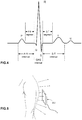
- the system may be designed to acquire the full PQRSTU spectrum constituent ECG waveforms as exemplified in Fig.4 which illustrates an example of a full PQRSTU waveform obtained for a patient using a system in accordance with an embodiment.
- the PQRSTU waveforms illustrated in Fig.4 are generated by the heart and captured by the system to be viewed by doctors for diagnosis.
- the system captures the ECG readings and processes them to produce ECG signals that may be read and viewed using existing medical equipment and produces waveforms that are identical to those produced by standard contact ECG systems, and as such can be used in place of standard ECG systems for all applications.
- the contactless sensors 10 do not produce an output that is compatible with existing medical equipment's (e.g. monitors and the like) and therefore cannot interface with these equipment, hence the need for further processing.
- the DPM converts the acquired signal into a format that complies with the international standards for existing medical equipment. This allows for a seamless replacement of conventional contact ECG systems without the need to replace existing diagnostic medical devices or retrain doctors and medical professionals. Such conversion may be performed in the DPM 2 using a combination of digital signal processing and analog output circuitry in the Digital to Analog Converter stage (19).
- the embodiments obtain ECG readings of the patient using contactless ECG sensors 10.
- the sensors 10 are specifically designed to capture high quality ECG from a patient without requiring direct electrical contact with the patient's skin. This allows to place the sensors 10 at some distance from the patient and/or to be separated from the patient's skin by a fabric such as clothing, bedding, etc. as exemplified in Fig.5 which illustrates an example of how the senor array captures ECG signals without direct contact with the patient's skin.
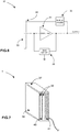
- Fig.6 is a block diagram illustrating an exemplary sensor design in accordance with an embodiment.
- the sensor 10 may include a conductive electrode 33, an electrode shield 32, and an electrodynamic sensor including an amplifier 34 and a bias circuit 35 voltage.
- the gain / current buffering amplifier 34 may be used in a type of negative feedback topology, and the input bias network 35 is adapted to increase the effective input impedance of the amplifier 34, to preserve the signal quality of the acquired ECG.
- the input of the electrodynamic sensor is connected to the conductive electrode 33.
- a shield driving circuitry (36) may be employed to generate a feedback signal to connect to the electrode shield (32) to further increase the signal to noise (SNR) ratio by reducing parasitic capacitance seen at the input of the electrodynamic sensor.
- SNR signal to noise
- the electrode 33 is capacitively coupled to the patient's body by being in proximity to, but not touching the skin/body. This can be accomplished by laying on a bed with an array of sensors 10 embedded in it (as non-limiting example of implementation), while clothed.
- the electric field near the surface of the patient's skin that is created from the electrical activity of the heart capacitively induces a charge on the conductive electrode 33 without direct electrical contact. This charge may then be collected and amplified by the electrodynamic sensor, which produces an electrical signal (voltage) that is representative of the electrical activity of the heart in that location (complete PQRSTU).
- the electrode shield 32 is configured to reduce the amount of stray interference that the electrodynamic sensor receives and also decrease the effective capacitance of the input of the amplifier 34, which helps to preserve signal quality of the acquired ECG.
- both the electrode 33 and the electrode shield 32 may be made of an elastic/flexible material which allows the sensor 10 to better adapt to the geometry of the human body and obtain better ECG readings. At the same time this configuration allows the sensors 10 to be seamlessly provided in the fabric (or any of the following: gel/silicone/rubber type pad/mat etc.) in which the sensor array is to be placed.
- Fig.7 illustrates an example of a physical design of the sensor 10.
- the physical design includes the conductive electrode 33 physically implemented as a layer 39, the shield 32 physically implemented as the layer 40, and the remaining of the circuitry embedded in the layer 41.
- the entire structure may be produced on a substrate 37 which may also be a printed circuit board, for example.
- the layers 39, 40 and 41 may be insulated from each other by dielectric layers 38 to provide electrical insulation.
- Fig.8 illustrates an exemplary block diagram of an overall design of a system.
- the system may include a sensor pad 7 comprising contactless ECG sensors (hereinafter CECG sensors 10) which may be provided in the form of an array 202 such as that shown in Fig.2 .
- the sensor pad 7 may also include a grounding pad 15, a driving circuitry e.g. a right leg drive (RLD) generator 14 (discussed below), and an A/D converter 13.
- the sensor pad 7 outputs the digitized ECG readings of the sensors 10 to the DPM 2.
- the RLD generator 14 is configured to feed the grounding pad 15 with a high frequency signal that is outside of the ECG frequency band.
- This high frequency signal is then coupled through the patient's body to the CECG sensors, where the amplitude is recorded and analyzed by the DPM 2. This gives the system a metric of how well-coupled each sensor is to the patient, effectively an impedance measurement to determine what the signal quality is from each sensor.
- the DPM 2 may also be configured to receive standard ECG data of conventional electrodes in an analog format. Such analog ECG data is optionally acquired through the use of standard contact electrodes and a trunk cable (5).
- the analog signals may be converted using an ADC 17.
- the signals may then be filtered using a digital signal processing unit 18, and output over a variety of wired and wireless interfaces (Wi-Fi (22) / Ethernet (23) to a mobile app (3) / cloud server (4) and through the 'Analog CECG & ECG out' interface to existing medical equipment (6)).
- the DPM 2 may include some sort of non-volatile memory e.g. flash memory 26 for storage of ECG data (if necessary).
- the DPM 2 may also be configured to perform diagnosis for acute issues, and send a warning over any one of the communication interfaces or an integrated sound alarm (24).
- the DPM 2 may also include a Bluetooth Low Energy interface (21) to enable configuration by the user through a mobile device.
- a Read Only Memory (25) may also be included to store a unique identifier.
- a Cryptographic processing module (27) may also be used to encrypt and decrypt data transmitted/received through the communication interfaces, and securely stores keys for this data encryption.
- All sensor data can be sent over the wired and wireless interfaces.
- the selection algorithm 204 decides which sensor information should be output over the analog interface 19 to existing medical equipment.
- a relay 20 may be provided to switch between the analog data received from the conventional electrodes and the contactless sensors 10 and to allow the DPM 2 to compare between the two.
- DPM 2 can be configured to be turned off to act like a pass-through cable, without affecting the contact ECG signal if desired (controlled by the Processing Unit and Relays (20)). It can also be used in 'hybrid mode', during which a combination of CECG and ECG sensors can be output over the analog interface, if it improves the quality of the ECG signal.
- a gain control mechanism is provided which allows the system to control relative impedance differences between different contactless ECG sensors, and an absolute impedance between each contactless ECG sensor and the human body due to a difference in distance between each contactless ECG sensor and the human body.
- a programmable gain amplifier 43 (either in the analog or digital domains) may be provided on each sensor channel 42 to offset the change in gain caused by differences in coupling between the sensors 10 and the patient.
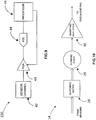
- Fig.9 is a block diagram illustrating an exemplary gain control mechanism.
- the gain control mechanism 220 may include a feedback loop including an ADC 44 coupled between the PGA 43 and a processor 45 which itself is connected to the PGA 43 to control its gain in real-time as the change is occurring.
- the processor 45 may be a dedicated processor and may also be a processor module embedded into the processing unit 18 of the DPM 2.
- a grounding pad 15 which in operation should be placed near, but not in contact with (at a distance), the patient's body.
- This pad is driven with a feedback signal derived from the ECG signals to provide a capacitively coupled ground reference to the patient's body.
- the feedback signal is derived in such a way to increase the common mode rejection ratio (CMRR) of the system (by over 10dB, typically). This reduces interference from common mode signals and preserves the signal quality of the acquired ECG.
- CMRR common mode rejection ratio
- Fig.10 is an exemplary block diagram illustrating the function of the RLD generator 14. As shown in Fig.10 , data received from the sensors is selected (or discarded) using a switching matrix (29) which selects specific sensors 10 to obtain data from using an RLD algorithm implemented digitally in the processing unit (18). The signals are then summed (29), inverted and amplified (30). This constitutes the driving signal for the grounding pad 15.
- the RLD algorithm is configured to monitor the common mode signal acquired from each sensor (and by extension, the ECG signals output from selection algorithm).
- the RLD algorithm may select the set of sensors that increases the common mode rejection ratio of the system after the RLD signal is applied to the patient in the feedback configuration.
- Hallmarks may include
- a 16 lead ECG can be acquired from the patient laying on the matrix of sensors, embedded in a mattress, chair, etc,.
- the acquired leads include: Leads I, II, III, aVr, aVI, aVf, V1, V1R, V2, V2R, V3, V3R, V4, V4R, V5, V5R as exemplified in Fig.11 and Fig.12.
- Fig.11 shows medically recognized ECG locations for obtaining standard ECG leads
- Fig.12 illustrates an example of standard ECG leads, each lead being shown as a vector between two locations on the human body.
- the pad including the sensors 10 can be placed, unperceivably under a mattress so that ECG data can be acquired from posterior leads; e.g. the prone position.
- the system may be based on the Mason-Likar sensor placement used for the acquisition of the ECG during stress testing. Standard 12 lead ECG placement is not used because of myopotentials, motion, artifacts, etc. and is limited to the 10 second 12 lead ECG printout and is not practical for short to long term monitoring.
- Posterior placed electrodes are an accepted method of ECG acquisition, and indeed are used as an adjunct in certain situations to the more commonly used method of anterior lead placements.
- Anterior lead placement is currently the only type of lead placement used because of convenience.
- prone position ECG leads are performed in certain situations with standard electrodes, but because of the inherent difficulties, is not a standard.
- Fig.14 is a flowchart of a method for providing electrocardiogram (ECG) signals for a human body using contactless ECG sensors.
- the method 260 begins at step 262 by receiving contactless ECG signals from an array of contactless ECG sensors.
- Step 264 comprises detecting body parts located in proximity of the array of contactless ECG sensors.
- Step 266 comprises selecting from each group a contactless ECG sensor having a highest signal quality.
- Step 268 comprises producing a standard ECG signal based on the contactless ECG signal of each selected contactless ECG sensor.
Landscapes
- Health & Medical Sciences (AREA)
- Life Sciences & Earth Sciences (AREA)
- Engineering & Computer Science (AREA)
- Veterinary Medicine (AREA)
- Pathology (AREA)
- Biophysics (AREA)
- Biomedical Technology (AREA)
- Heart & Thoracic Surgery (AREA)
- Medical Informatics (AREA)
- Molecular Biology (AREA)
- Surgery (AREA)
- Animal Behavior & Ethology (AREA)
- General Health & Medical Sciences (AREA)
- Public Health (AREA)
- Physics & Mathematics (AREA)
- Cardiology (AREA)
- Physiology (AREA)
- Signal Processing (AREA)
- Artificial Intelligence (AREA)
- Psychiatry (AREA)
- Computer Vision & Pattern Recognition (AREA)
- Dentistry (AREA)
- Oral & Maxillofacial Surgery (AREA)
- Microelectronics & Electronic Packaging (AREA)
- Power Engineering (AREA)
- Nuclear Medicine, Radiotherapy & Molecular Imaging (AREA)
- Radiology & Medical Imaging (AREA)
- Measurement And Recording Of Electrical Phenomena And Electrical Characteristics Of The Living Body (AREA)
- Computer Networks & Wireless Communication (AREA)
Claims (15)
- Digitales Verarbeitungsmodul (DPM) (2) zum Bereitstellen von Elektrokardiogramm-(EKG-)Signalen für einen menschlichen Körper zur Speicherung und/oder Betrachtung auf einem entfernten/lokalen Gerät, wobei das DPM (2) umfasst:- einen Eingang, der eingerichtet ist, kontaktlose EKG-Signale für den menschlichen Körper von einem in der Nähe des menschlichen Körpers angeordneten Arrays von kontaktlosen EKG-Sensoren (10) zu empfangen;- einen Prozessor, der eingerichtet ist, ein Auswahlverfahren durchzuführen, enthaltend∘ Gewinnen einer Körperkontur (252) des menschlichen Körpers basierend auf der Qualität jedes kontaktlosen EKG-Signals, das mit jedem kontaktlosen EKG-Sensor (10) verknüpft ist;∘ Erkennen eines oder mehrerer Körperteile, die sich in der Körperkontur (252) befinden, unter Verwendung eines Satzes von in dem DPM (2) eingebetteter Regeln;∘ Verknüpfen einer Gruppe von kontaktlosen EKG-Sensoren (10) mit jedem erkannten Körperteil;∘ Auswählen eines kontaktlosen EKG-Sensors (10) aus jeder Gruppe, der eine höchste Signalqualität für den mit dieser Gruppe von kontaktlosen EKG-Sensoren (10) verknüpften Körperteil aufweist;wobei der Prozessor eingerichtet ist, ein Standard-EKG-Signal basierend auf den kontaktlosen EKG-Signalen zu erzeugen, die von den ausgewählten kontaktlosen EKG-Sensoren (10) empfangen werden; und- einen Ausgang zum Senden des Standard-EKG-Signals an das entfernte/lokale Gerät,wobei die kontaktlosen EKG-Sensoren (10) jeweils eine kapazitive Elektrode aufweisen.
- DPM (2) nach Anspruch 1, wobei der Prozessor weiterhin eingerichtet ist zum Durchführen der Schritte:a. Bestimmen einer Position des menschlichen Körpers auf dem Array von kontaktlosen EKG-Sensoren (10);b. Einteilen der kontaktlosen EKG-Sensoren (10) in Gruppen und Verknüpfen jeder Gruppe mit einem Körperteil unter Verwendung des Körperumrisses (252) und der Position des menschlichen Körpers;c. für jede Gruppe Auswählen des kontaktlosen EKG-Sensors (10), der die höchste Signalqualität bereitstellt.
- DPM (2) nach Anspruch 2, wobei der Prozessor die kontaktlosen EKG-Sensoren (10) identifiziert, die sich in unmittelbarer Nähe des menschlichen Körpers befinden, durch Messen einer Impedanz zwischen jedem kontaktlosen EKG-Sensor (10) und dem menschlichen Körper.
- DPM (2) nach Anspruch 1, wobei das DPM (2) eingerichtet ist, einer Bewegung des menschlichen Körpers in Bezug auf das Array von kontaktlosen EKG-Sensoren (10) folgend, einen anderen kontaktlosen EKG-Sensors (10) für einen gegebenen Körperteil auszuwählen.
- DPM (2) nach Anspruch 4, wobei der Prozessor eingerichtet ist, den Auswahlprozess kontinuierlich erneut zu starten, um die Auswahl des anderen kontaktlosen EKG-Sensors (10) durchzuführen, oder wobei der Prozessor eingerichtet ist, eine aktuelle Signalqualität des ausgewählten kontaktlosen EKG-Sensors (10), der mit jedem Körperteil verknüpft ist, kontinuierlich zu überwachen, um den Auswahlprozess erneut zu starten, wenn die aktuelle Signalqualität über einen gegebenen Schwellenwert hinaus abfällt.
- DPM (2) nach Anspruch 1, wobei das DPM (2) verschiedene Betriebsarten umfasst, umfassend:- einen kontaktlosen Modus, der ein erstes Standard-EKG-Signal ausgibt, das sich aus den kontaktlosen EKG-Signalen ergibt;- einen Hybridmodus, der ein zweites Standard-EKG-Signal ausgibt, das sich aus den kontaktlosen EKG-Signalen und konventionellen EKG-Signalen ergibt, die von konventionellen Kontaktelektroden empfangen werden; und- einen Bypass-Modus, der ein drittes Standard-EKG-Signal ausgibt, das sich aus konventionellen EKG-Signalen ergibt, die von konventionellen Kontaktelektroden empfangen werden.
- DPM (2) nach Anspruch 1,a) weiterhin umfassend einen automatischen Verstärkungsregelungsmechanismus (220), der eingerichtet ist, relative Impedanzunterschiede zwischen verschiedenen kontaktlosen EKG-Sensoren (10) und einer absolute Impedanz zwischen jedem kontaktlosen EKG-Sensor (10) und dem menschlichen Körper aufgrund eines Unterschieds im Abstand oder Art des Bekleidungsmaterials zwischen jedem kontaktlosen EKG-Sensor (10) und dem menschlichen Körper zu regeln; oderb) weiterhin umfassend einen drahtgebundenen/drahtlosen Datenport zur Übertragung des Standard-EKG-Signals an ein entferntes Gerät über ein Datennetzwerk.
- System (200) zum Bereitstellen von Elektrokardiogramm-(EKG-)Signalen für einen menschlichen Körper zur Speicherung und/oder Betrachtung auf einem entfernten/lokalen Gerät, das System (200) umfassend:- ein Sensorpad (7) umfassend ein Array von kontaktlosen EKG-Sensoren (10); und- ein digitales Verarbeitungsmodul (DPM) (2) gemäß Anspruch 1.
- System (200) nach Anspruch 8, wobei das Sensorpad (7) ein Erdungspad (15) zur Anordnung in der Nähe des und in einem Abstand zu dem menschlichen Körper umfasst, wobei das Erdungspad (15) eingerichtet ist, eine kapazitiv gekoppelte Erdungsreferenz zum menschlichen Körper zur Verringerung von Störungen bereitzustellen.
- System (200) nach Anspruch 9, wobei das Erdungspad (15) mit einem Rückkopplungssignal angesteuert wird, das von den kontaktlosen EKG-Signalen abgeleitet wird, oder weiterhin umfassend einen Ansteuersignalgenerator (14), der konfiguriert ist, das Erdungspad (15) mit einem Hochfrequenzsignal zu speisen, das außerhalb eines EKG-Frequenzbandes liegt, um die kapazitiv gekoppelte Erdungsreferenz für jeden kontaktlosen EKG-Sensor (10) zu bestimmen.
- System (200) nach Anspruch 8, wobei der kontaktlose EKG-Sensor (10) umfasst:- eine kapazitive Elektrode (33), die eingerichtet ist, kapazitiv an den menschlichen Körper gekoppelt zu werden, um eine elektrische Ladung abzugeben, die repräsentativ für eine elektrische Herzaktivität ist;- einen elektrodynamischen Sensor, der konfiguriert ist zum Erfassen und Verstärken der von der kapazitiven Elektrode erzeugten elektrischen Ladung; und- eine Elektrodenabschirmung (32), die physisch in der Nähe der Elektrode (33) vorgesehen ist, um eine Streuinterferenz an einem Eingang des elektrodynamischen Sensors zu reduzieren.
- System (200) nach Anspruch 11, wobei der kontaktlose EKG-Sensor (10) aus einem flexiblen Material hergestellt ist oder wobei das Sensorpad (7) in einem Gewebe, mit dem der menschliche Körper in Kontakt kommt, oder in einem der folgenden vorgesehen ist: einem Gel, Silikon, einem Pad vom gummityp und einer Matte.
- Verfahren zum Bereitstellen von Elektrokardiogramm- (EKG-) Signalen für einen menschlichen Körper unter Verwendung kontaktloser EKG-Sensoren (10) und eines Prozessors, das Verfahren umfassend:- Empfangen kontaktloser EKG-Signale von einem Array von kontaktlosen EKG-Sensoren (10), die in der Nähe des menschlichen Körpers angeordnet sind;wobei der Prozessor eingerichtet ist, einen Auswahlprozess durchzuführen, enthaltend:- Gewinnen einer Körperkontur (252) des menschlichen Körpers basierend auf der Qualität jedes kontaktlosen EKG-Signals, das mit jedem kontaktlosen EKG-Sensor (10) verknüpft ist;- Erkennen eines oder mehrerer Körperteile, die sich in der Körperkontur (252) befinden, unter Verwendung eines Satzes von in einem DPM (2) eingebetteter Regeln;- Verknüpfen einer Gruppe von kontaktlosen EKG-Sensoren (10) mit jedem erkannten Körperteil;- Auswählen eines kontaktlosen EKG-Sensors (10) aus jeder Gruppe, der eine höchste Signalqualität für den mit dieser Gruppe von kontaktlosen EKG-Sensoren (10) verknüpften Körperteil aufweist;wobei der Prozessor weiterhin eingerichtet ist zum:- Erzeugen und Ausgeben eines Standard-EKG-Signals basierend auf den kontaktlosen EKG-Signalen, die von den ausgewählten kontaktlosen EKG-Sensoren (10) empfangen werden,wobei die kontaktlosen EKG-Sensoren (10) jeweils eine kapazitive Elektrode umfassen.
- Verfahren nach Anspruch 13, weiterhin umfassend:- Bestimmen einer Position des menschlichen Körpers auf dem Array von kontaktlosen EKG-Sensoren (10);- Einteilen der kontaktlosen EKG-Sensoren (10) in Gruppen und Verknüpfen jeder Gruppe zu einem Körperteil unter Verwendung des Körperumrisses (252) und der Position des menschlichen Körpers;- für jede Gruppe, Auswählen des kontaktlosen EKG-Sensors (10), der das kontaktlose EKG-Signal mit der höchsten Qualität bereitstellt, insbesondereweiterhin umfassend Identifizieren der kontaktlosen EKG-Sensoren (10), die sich in unmittelbarer Nähe des menschlichen Körpers befinden, durch Messen einer Impedanz zwischen jedem kontaktlosen EKG-Sensor (10) und dem menschlichen Körper.
- Verfahren nach Anspruch 13,a) weiterhin umfassend: Wiederholen der Schritte des Erfassens bis zum kontinuierlichen Auswählen, um, einer Bewegung des menschlichen Körpers in Bezug auf das Array von kontaktlosen EKG-Sensoren (10) folgend, einen anderen kontaktlosen EKG-Sensor (10) für einen gegebenen Körperteil auszuwählen; oderb) weiterhin umfassend kontinuierliches Überwachen einer Stromsignalqualität des ausgewählten kontaktlosen EKG-Sensors (10), der mit jedem Körperteil verknüpft ist, und Wiederholen der Schritte des Erfassens bis zum Auswählen zur Auswahl eines anderen kontaktlosen EKG-Sensors (10) für einen gegebenen Körperteil, wenn, einer Bewegung des menschlichen Körpers in Bezug auf das Array von kontaktlosen EKG-Sensoren (10) folgend, die Stromsignalqualität über einen gegebenen Schwellenwert hinaus abfällt; oderc) weiterhin umfassend Regeln relativer Impedanzunterschiede zwischen verschiedenen kontaktlosen EKG-Sensoren (10) und einer absoluten Impedanz zwischen jedem kontaktlosen EKG-Sensor (10) und dem menschlichen Körper aufgrund eines Abstandsunterschiedes oder Art von Bekleidungsmaterial zwischen jedem kontaktlosen EKG-Sensor (10) und dem menschlichen Körper.
Priority Applications (1)
| Application Number | Priority Date | Filing Date | Title |
|---|---|---|---|
| EP20179908.7A EP3785621A1 (de) | 2014-09-23 | 2015-09-23 | Kontaktlose elektrokardiographie |
Applications Claiming Priority (3)
| Application Number | Priority Date | Filing Date | Title |
|---|---|---|---|
| US201462054189P | 2014-09-23 | 2014-09-23 | |
| US201562206542P | 2015-08-18 | 2015-08-18 | |
| PCT/CA2015/050938 WO2016044933A1 (en) | 2014-09-23 | 2015-09-23 | Contactless electric cardiogram system |
Related Child Applications (2)
| Application Number | Title | Priority Date | Filing Date |
|---|---|---|---|
| EP20179908.7A Division-Into EP3785621A1 (de) | 2014-09-23 | 2015-09-23 | Kontaktlose elektrokardiographie |
| EP20179908.7A Division EP3785621A1 (de) | 2014-09-23 | 2015-09-23 | Kontaktlose elektrokardiographie |
Publications (3)
| Publication Number | Publication Date |
|---|---|
| EP3038523A1 EP3038523A1 (de) | 2016-07-06 |
| EP3038523A4 EP3038523A4 (de) | 2017-05-10 |
| EP3038523B1 true EP3038523B1 (de) | 2020-11-25 |
Family
ID=55579995
Family Applications (2)
| Application Number | Title | Priority Date | Filing Date |
|---|---|---|---|
| EP15794450.5A Active EP3038523B1 (de) | 2014-09-23 | 2015-09-23 | Kontaktlose elektrokardiographie |
| EP20179908.7A Pending EP3785621A1 (de) | 2014-09-23 | 2015-09-23 | Kontaktlose elektrokardiographie |
Family Applications After (1)
| Application Number | Title | Priority Date | Filing Date |
|---|---|---|---|
| EP20179908.7A Pending EP3785621A1 (de) | 2014-09-23 | 2015-09-23 | Kontaktlose elektrokardiographie |
Country Status (15)
| Country | Link |
|---|---|
| US (4) | US10052042B2 (de) |
| EP (2) | EP3038523B1 (de) |
| JP (1) | JP6646050B2 (de) |
| KR (1) | KR101946174B1 (de) |
| CN (1) | CN107205678B (de) |
| AU (1) | AU2015321376B2 (de) |
| BR (1) | BR112016030185A2 (de) |
| CA (1) | CA2911304C (de) |
| ES (1) | ES2843690T3 (de) |
| HK (1) | HK1222307A1 (de) |
| IL (1) | IL251321B (de) |
| RU (1) | RU2677767C2 (de) |
| SG (1) | SG11201610065UA (de) |
| WO (1) | WO2016044933A1 (de) |
| ZA (1) | ZA201700649B (de) |
Families Citing this family (28)
| Publication number | Priority date | Publication date | Assignee | Title |
|---|---|---|---|---|
| WO2011020216A1 (zh) * | 2009-08-18 | 2011-02-24 | Yang Changming | 侦测生理机能及姿势状态的物品、方法和系统 |
| RU2677767C2 (ru) | 2014-09-23 | 2019-01-21 | Рр Сиквенсис Инк. | Система бесконтактной регистрации электрокардиограммы |
| US9808202B2 (en) * | 2014-11-28 | 2017-11-07 | Shenzhen Novocare Medical Devices Co, INC | Mattress for measuring physiological parameters of heart |
| US20170231545A1 (en) * | 2016-02-14 | 2017-08-17 | Earlysense Ltd. | Apparatus and methods for monitoring a subject |
| EP3243430A1 (de) * | 2016-05-12 | 2017-11-15 | IMEC vzw | Vorrichtung und verfahren zum steuern der erfassung von eines signals und system zur erfassung eines signals |
| WO2018020454A1 (en) * | 2016-07-29 | 2018-02-01 | Shingrani Rahul | Method and system for cardiac health monitoring |
| JP6778043B2 (ja) * | 2016-08-04 | 2020-10-28 | フクダ電子株式会社 | 心電図記録装置 |
| CN106264517B (zh) * | 2016-09-30 | 2019-05-14 | 浙江大学 | 一种选择心电测量位置的方法及系统 |
| CN106691432B (zh) * | 2016-10-19 | 2023-04-21 | 深圳市杰纳瑞医疗仪器股份有限公司 | 感应式心电测量方法与装置 |
| US10307073B2 (en) | 2016-12-21 | 2019-06-04 | General Electric Company | ECG sensor with capacitive defibrillation protection |
| US10517488B2 (en) * | 2016-12-21 | 2019-12-31 | General Electric Company | Patient monitoring system and leadset having multiple capacitive patient connectors and a single galvanic patient connector |
| JP2018102710A (ja) * | 2016-12-27 | 2018-07-05 | 株式会社豊田中央研究所 | 心電計測装置、方法及びプログラム |
| JP6800443B2 (ja) * | 2017-01-31 | 2020-12-16 | 国立研究開発法人産業技術総合研究所 | 生体情報検出センサ及び生体情報測定システム |
| US10555679B2 (en) * | 2017-06-20 | 2020-02-11 | General Electric Company | Non-contact heart rate monitoring |
| MX2020001839A (es) * | 2017-09-01 | 2020-07-14 | Nestle Sa | Dispositivo de deteccion de la frecuencia cardiaca y sistemas y metodos relacionados. |
| US10499827B2 (en) * | 2017-09-19 | 2019-12-10 | Honeywell International Inc. | System and method for interpretation of signal-to-noise ratios detected in an array of electrodes sensors in terms of physical and cognitive state |
| US20190184853A1 (en) * | 2017-12-19 | 2019-06-20 | GM Global Technology Operations LLC | Occupant sensing system for a vehicle |
| CN113164122A (zh) * | 2018-11-12 | 2021-07-23 | 迈恩特公司 | 多传感器电阻织造物ecg系统 |
| TWI715022B (zh) * | 2019-04-29 | 2021-01-01 | 宏碁股份有限公司 | 智慧照護床墊及偵測使用者生理狀態的方法 |
| CN111956229B (zh) * | 2019-05-20 | 2023-05-23 | 宏碁股份有限公司 | 智能照护床垫及侦测使用者生理状态的方法 |
| WO2020255141A2 (en) * | 2019-06-20 | 2020-12-24 | Omnysense Ltd | A method for increasing cannabis yield via gene editing |
| US20210000348A1 (en) * | 2019-07-01 | 2021-01-07 | Wolfgang Richter | Apparatus for measuring vital signs |
| CN110426427A (zh) * | 2019-09-07 | 2019-11-08 | 中国科学院宁波材料技术与工程研究所 | 一种电容耦合传感器、其制备方法与应用 |
| US20230165501A1 (en) * | 2020-04-03 | 2023-06-01 | Easyg Llc | System and methods for contactless monitoring of heart muscle activity and identifying medical conditions based on biopotential signals |
| US11806115B2 (en) * | 2020-05-21 | 2023-11-07 | GE Precision Healthcare LLC | Systems and methods for dynamic selection of sensors for obtaining physiological data from a patient |
| US20220039723A1 (en) * | 2020-08-07 | 2022-02-10 | Verily Life Sciences Llc | Multi-lead measurement of biopotentials with wearable device |
| CN113440347A (zh) * | 2021-01-11 | 2021-09-28 | 宁波市第九医院 | 一种集成非接触式心肺功能实时监测及评估的电动起立床 |
| FR3131524A1 (fr) * | 2021-12-31 | 2023-07-07 | Withings | Station de mesure avec mesure d’électrocardiogramme |
Family Cites Families (102)
| Publication number | Priority date | Publication date | Assignee | Title |
|---|---|---|---|---|
| US5010772A (en) | 1986-04-11 | 1991-04-30 | Purdue Research Foundation | Pressure mapping system with capacitive measuring pad |
| US5353793A (en) | 1991-11-25 | 1994-10-11 | Oishi-Kogyo Company | Sensor apparatus |
| US6551252B2 (en) | 2000-04-17 | 2003-04-22 | Vivometrics, Inc. | Systems and methods for ambulatory monitoring of physiological signs |
| US5944669A (en) | 1997-11-20 | 1999-08-31 | Lifecor, Inc. | Apparatus and method for sensing cardiac function |
| US6553246B1 (en) | 1998-02-12 | 2003-04-22 | Unilead International, Inc. | Universal electrocardiogram sensor positioning device and method for four sizes including extra large |
| IL124900A0 (en) | 1998-06-14 | 1999-01-26 | Tapuz Med Tech Ltd | Apron for performing ecg tests and additional examinations |
| US6745062B1 (en) | 1998-10-05 | 2004-06-01 | Advanced Imaging Systems, Inc. | Emg electrode apparatus and positioning system |
| EP1204367B1 (de) | 1999-07-21 | 2007-04-18 | Daniel David | Physiologisches messsystem mit kleidungsstück in der form einer hülle oder eines handschuhs und darin integriertem messgerät |
| US20050131465A1 (en) | 2000-02-04 | 2005-06-16 | Freeman Gary A. | Integrated resuscitation |
| US6584343B1 (en) | 2000-03-15 | 2003-06-24 | Resolution Medical, Inc. | Multi-electrode panel system for sensing electrical activity of the heart |
| US7485095B2 (en) | 2000-05-30 | 2009-02-03 | Vladimir Shusterman | Measurement and analysis of trends in physiological and/or health data |
| US6560473B2 (en) | 2001-03-02 | 2003-05-06 | Steven Dominguez | Disposable ECG chest electrode template with built-in defibrillation electrodes |
| US6847836B1 (en) | 2002-02-08 | 2005-01-25 | Lenny Sujdak | Emergency ECG electrode chest pad |
| US6932774B2 (en) | 2002-06-27 | 2005-08-23 | Denso Corporation | Respiratory monitoring system |
| US6961601B2 (en) | 2003-06-11 | 2005-11-01 | Quantum Applied Science & Research, Inc. | Sensor system for measuring biopotentials |
| US7559902B2 (en) | 2003-08-22 | 2009-07-14 | Foster-Miller, Inc. | Physiological monitoring garment |
| EP2319410A1 (de) | 2003-09-12 | 2011-05-11 | BodyMedia, Inc. | Vorrichtung zur Messung von Herzparametern |
| US20050137464A1 (en) * | 2003-12-23 | 2005-06-23 | Bomba Frank C. | Wireless sensor and sensor initialization device and method |
| US7254439B2 (en) | 2004-01-06 | 2007-08-07 | Monebo Technologies, Inc. | Method and system for contactless evaluation of fatigue of an operator |
| JP3809454B2 (ja) | 2004-06-01 | 2006-08-16 | 独立行政法人科学技術振興機構 | 心臓磁界診断装置およびその作動方法 |
| US7245956B2 (en) | 2004-07-15 | 2007-07-17 | Quantum Applied Science & Research, Inc. | Unobtrusive measurement system for bioelectric signals |
| KR100736721B1 (ko) | 2004-08-31 | 2007-07-09 | 재단법인서울대학교산학협력재단 | 전기적 비접촉 심전도 측정장치 및 그에 따른 측정방법 |
| US20090138059A1 (en) * | 2004-12-08 | 2009-05-28 | Koninklijke Philips Electronics N.V. | Heart Defibrillator With Contactless ECG Sensor For Diagnostics/Effectivity Feedback |
| JP5269584B2 (ja) | 2005-03-25 | 2013-08-21 | ゾール メディカル コーポレイション | 統合された蘇生 |
| JP5253156B2 (ja) * | 2005-06-07 | 2013-07-31 | コーニンクレッカ フィリップス エレクトロニクス エヌ ヴィ | 患者モニタリングシステム及び方法 |
| US7712373B2 (en) | 2006-03-03 | 2010-05-11 | Nagle H Troy | Sensor device for real-time monitoring or relative movement using capacitive fabric sensors |
| US7616980B2 (en) | 2006-05-08 | 2009-11-10 | Tyco Healthcare Group Lp | Radial electrode array |
| US9101264B2 (en) | 2006-06-15 | 2015-08-11 | Peerbridge Health, Inc. | Wireless electrode arrangement and method for patient monitoring via electrocardiography |
| US9131892B2 (en) | 2006-07-25 | 2015-09-15 | Gal Markel | Wearable items providing physiological, environmental and situational parameter monitoring |
| WO2008056309A2 (en) * | 2006-11-10 | 2008-05-15 | Koninklijke Philips Electronics, N.V. | Ecg electrode contact quality measurement system |
| US8238996B2 (en) | 2006-12-05 | 2012-08-07 | Tyco Healthcare Group Lp | Electrode array |
| US8140154B2 (en) | 2007-06-13 | 2012-03-20 | Zoll Medical Corporation | Wearable medical treatment device |
| US7974689B2 (en) | 2007-06-13 | 2011-07-05 | Zoll Medical Corporation | Wearable medical treatment device with motion/position detection |
| US7996056B2 (en) | 2007-06-15 | 2011-08-09 | The General Electric Company | Method and apparatus for acquiring physiological data |
| US8060175B2 (en) | 2007-06-15 | 2011-11-15 | General Electric Company | System and apparatus for collecting physiological signals from a plurality of electrodes |
| US20090088652A1 (en) | 2007-09-28 | 2009-04-02 | Kathleen Tremblay | Physiological sensor placement and signal transmission device |
| KR20100103537A (ko) | 2007-11-28 | 2010-09-27 | 더 리전츠 오브 더 유니버시티 오브 캘리포니아 | 비-접촉 생체 전위 감지기 |
| CN101896120B (zh) * | 2007-12-12 | 2012-10-10 | 皇家飞利浦电子股份有限公司 | 睡眠体位的检测 |
| JP5535936B2 (ja) | 2007-12-20 | 2014-07-02 | コーニンクレッカ フィリップス エヌ ヴェ | 静電容量の検知及び通信 |
| KR20110008080A (ko) | 2008-04-03 | 2011-01-25 | 카이 메디컬, 아이엔씨. | 비접촉식 생리학적 모션 센서 및 모션 센서의 사용 방법 |
| CN102046076A (zh) * | 2008-04-03 | 2011-05-04 | Kai医药公司 | 非接触式生理运动传感器及其使用方法 |
| EP2826829B1 (de) * | 2008-08-06 | 2018-05-16 | Flexcon Company, Inc. | Biomedizinisches Sensorsystem und Verfahren zum Detektieren eines sich zeitlich ändernden biomedizinischen Signals |
| US8870780B2 (en) | 2008-10-15 | 2014-10-28 | The Board Of Trustees Of The Leland Stanford Junior University | Systems and methods for monitoring heart function |
| KR101040653B1 (ko) | 2009-01-21 | 2011-06-10 | 서울대학교산학협력단 | 비접촉 광용적맥파 측정장치와 이를 이용한 산소포화도 측정장치 및 혈압 측정장치 |
| JP2010194137A (ja) | 2009-02-26 | 2010-09-09 | Ritsumeikan | 非接触心電図センサ |
| KR101007818B1 (ko) * | 2009-05-27 | 2011-01-14 | (주)경원유글로브 | 비접촉식 심장 박동 측정 센서 및 이를 이용한 신호 처리 방법 |
| US8374701B2 (en) | 2009-07-28 | 2013-02-12 | The Invention Science Fund I, Llc | Stimulating a nervous system component of a mammal in response to contactlessly acquired information |
| US9697336B2 (en) | 2009-07-28 | 2017-07-04 | Gearbox, Llc | Electronically initiating an administration of a neuromodulation treatment regimen chosen in response to contactlessly acquired information |
| US8346354B2 (en) | 2009-07-28 | 2013-01-01 | The Invention Science Fund I, Llc | Determining a neuromodulation treatment regimen in response to contactlessly acquired information |
| WO2011146482A1 (en) | 2010-05-18 | 2011-11-24 | Zoll Medical Corporation | Wearable ambulatory medical device with multiple sensing electrodes |
| US8611828B2 (en) | 2010-06-30 | 2013-12-17 | Wolfgang Richter | System and methods for self-powered, contactless, self-communicating sensor devices |
| WO2012007860A1 (en) * | 2010-07-16 | 2012-01-19 | Koninklijke Philips Electronics N.V. | Device including a multi-actuator haptic surface for providing haptic effects on said surface. |
| US8483811B2 (en) | 2010-08-02 | 2013-07-09 | Empire Technology Development Llc | Detection of biological information of a subject |
| DE102010034192A1 (de) | 2010-08-12 | 2012-02-16 | Capical Gmbh | EKG-Handgerät |
| WO2012088398A2 (en) | 2010-12-22 | 2012-06-28 | Cardioinsight Technologies, Inc. | Multi-layered sensor apparatus |
| CA2825405A1 (en) | 2011-01-27 | 2012-08-02 | The Board Of Trustees Of The Leland Stanford Junior University | Systems and methods for monitoring the circulatory system |
| KR101227413B1 (ko) | 2011-03-08 | 2013-02-12 | (주)락싸 | 전기적 비접촉식 생체 신호 측정 장치 및 그 방법 |
| WO2012135028A1 (en) | 2011-03-25 | 2012-10-04 | Zoll Medical Corporation | Method of detecting signal clipping in a wearable ambulatory medical device |
| US8897860B2 (en) | 2011-03-25 | 2014-11-25 | Zoll Medical Corporation | Selection of optimal channel for rate determination |
| GB2489704B (en) * | 2011-04-04 | 2013-06-12 | Cardiocity Ltd | ECG mat |
| US9332919B2 (en) * | 2011-04-04 | 2016-05-10 | Cardiocity Limited | Heart monitoring apparatus |
| JP5370444B2 (ja) | 2011-09-05 | 2013-12-18 | 株式会社デンソー | 心電計 |
| WO2013075270A1 (zh) * | 2011-11-25 | 2013-05-30 | Yang Chang-Ming | 一种侦测心跳或电极接触良好与否的物品、方法及系统 |
| PT106102B (pt) | 2012-01-19 | 2014-08-11 | Inst Superior Técnico | Dispositivo e método para reconhecimento biométrico contínuo baseado em sinais eletrocardiográficos |
| US10182723B2 (en) | 2012-02-08 | 2019-01-22 | Easyg Llc | Electrode units for sensing physiological electrical activity |
| CN104717919B (zh) | 2012-02-08 | 2018-10-12 | 易赛格有限责任公司 | 具有多模式电极单元的ecg系统 |
| JP6068820B2 (ja) | 2012-04-19 | 2017-01-25 | テイ・エス テック株式会社 | 車両用シート |
| CN102657524B (zh) * | 2012-04-27 | 2013-11-20 | 东南大学 | 一种非接触式心电传感器及其应用 |
| US20150241505A1 (en) * | 2012-08-01 | 2015-08-27 | Draeger Medical Systems, Inc. | System And Method For Measuring Contact Impedance Of An Electrode |
| KR101316497B1 (ko) | 2012-08-03 | 2013-10-10 | 현대자동차주식회사 | 승객의 심박수 관찰시스템 및 관찰방법 |
| CN103845060A (zh) * | 2012-11-30 | 2014-06-11 | 中国科学院理化技术研究所 | 便携式胎动信号检测及分析装置 |
| US9037221B2 (en) | 2013-01-16 | 2015-05-19 | University Of Rochester | Non-contact electrocardiogram system |
| US9088282B2 (en) * | 2013-01-25 | 2015-07-21 | Apple Inc. | Proximity sensors with optical and electrical sensing capabilities |
| KR101440444B1 (ko) | 2013-01-31 | 2014-09-17 | 부경대학교 산학협력단 | 생체 신호를 측정하기 위한 전극 구조체 및 이를 이용한 심전도 측정 장치 |
| US20140249397A1 (en) | 2013-03-01 | 2014-09-04 | Thalmic Labs Inc. | Differential non-contact biopotential sensor |
| US9827431B2 (en) | 2013-04-02 | 2017-11-28 | West Affum Holdings Corp. | Wearable defibrillator with no long-term ECG monitoring |
| JP6298338B2 (ja) | 2013-04-25 | 2018-03-20 | 日本光電工業株式会社 | 電極パッド |
| TWM462093U (zh) | 2013-05-10 | 2013-09-21 | Wei-Chun Huang | 用於十二導程心電圖檢查的輔助裝置 |
| US9642543B2 (en) | 2013-05-23 | 2017-05-09 | Arizona Board Of Regents | Systems and methods for model-based non-contact physiological data acquisition |
| DE102013216604A1 (de) | 2013-08-22 | 2015-02-26 | Ford Global Technologies, Llc | Sensor zur berührungslosen elektrokardiographischen Messung, Sensorarray und Sitz oder Liege |
| DE102013216682A1 (de) | 2013-08-22 | 2015-02-26 | Ford Global Technologies, Llc | Sensor zur berührungslosen elektrokardiographischen Messung, Sensorarray und Sitz oder Liege |
| KR101536139B1 (ko) | 2013-09-05 | 2015-07-13 | 연세대학교 산학협력단 | 직물전극 키트 및 이를 장착한 동잡음 최소화 의복 |
| DE102013219026A1 (de) | 2013-09-23 | 2015-03-26 | Ford Global Technologies, Llc | Sensor zur berührungslosen elektrokardiographischen Messung, Sensorarray und Sitz oder Liege |
| WO2015045763A1 (ja) * | 2013-09-25 | 2015-04-02 | 日産自動車株式会社 | 生体電気信号計測用回路 |
| US10213124B2 (en) | 2013-09-25 | 2019-02-26 | Zoll Medical Corporation | Electrocardiogram package |
| DE102013219513A1 (de) | 2013-09-27 | 2015-04-02 | Ford Global Technologies, Llc | Sensor zur berührungslosen elektrokardiographischen Messung, Sensorarray und Sitz oder Liege |
| US20160256104A1 (en) | 2013-10-18 | 2016-09-08 | Healthwatch Ltd. | Independent wearable health monitoring system, adapted to interface with a treatment device |
| US10064566B2 (en) * | 2013-11-25 | 2018-09-04 | Koninklijke Philips N.V. | Electrocardiography monitoring system and method |
| US9320446B2 (en) | 2013-12-09 | 2016-04-26 | Medtronic, Inc. | Bioelectric sensor device and methods |
| WO2015127193A1 (en) | 2014-02-20 | 2015-08-27 | Faurecia Automotive Seating, Llc. | Vehicle seat with integrated sensors |
| RU2677767C2 (ru) | 2014-09-23 | 2019-01-21 | Рр Сиквенсис Инк. | Система бесконтактной регистрации электрокардиограммы |
| US9662030B2 (en) | 2014-10-01 | 2017-05-30 | Verily Life Sciences Llc | Electrocardiography device for garments |
| TW201617026A (zh) | 2014-11-11 | 2016-05-16 | 金寶電子工業股份有限公司 | 呼吸相關訊號量測系統及其量測方法 |
| US9808202B2 (en) | 2014-11-28 | 2017-11-07 | Shenzhen Novocare Medical Devices Co, INC | Mattress for measuring physiological parameters of heart |
| JP2016123852A (ja) | 2014-12-31 | 2016-07-11 | 現代自動車株式会社Hyundai Motor Company | 半接触式ecg測定システム及びその測定方法 |
| US10548495B2 (en) | 2015-04-01 | 2020-02-04 | Xtrava Inc. | Contactless or non-invasive physical properties measurement instrument using eddy current-reduced high Q resonant circuit probe |
| TWI565447B (zh) | 2015-07-31 | 2017-01-11 | 高雄榮民總醫院 | 快速心電圖檢測裝置 |
| KR101739542B1 (ko) | 2015-10-07 | 2017-06-08 | 주식회사 헬스리안 | 착용형 무선 12 채널 심전도 시스템 |
| FR3043902B1 (fr) | 2015-11-19 | 2018-02-23 | @Health | Procede et systeme d'acquisition et d'analyse de donnees physiologiques |
| US10758184B2 (en) | 2016-06-30 | 2020-09-01 | Washington State University | Self-operable, non-invasive, non-contact bio-signal monitoring |
| KR101912870B1 (ko) | 2016-09-29 | 2018-10-30 | 한국과학기술원 | 비접촉 심전도 측정 방법, 비접촉 심전도 측정 회로 및 이를 이용한 심전도 측정 장치 |
| US9986929B1 (en) | 2017-03-01 | 2018-06-05 | CB Innovations, LLC | Emergency cardiac and electrocardiogram electrode placement system |
-
2015
- 2015-09-23 RU RU2017109707A patent/RU2677767C2/ru active
- 2015-09-23 AU AU2015321376A patent/AU2015321376B2/en not_active Ceased
- 2015-09-23 CN CN201580050963.5A patent/CN107205678B/zh active Active
- 2015-09-23 SG SG11201610065UA patent/SG11201610065UA/en unknown
- 2015-09-23 WO PCT/CA2015/050938 patent/WO2016044933A1/en active Application Filing
- 2015-09-23 BR BR112016030185A patent/BR112016030185A2/pt not_active IP Right Cessation
- 2015-09-23 US US14/893,293 patent/US10052042B2/en not_active Expired - Fee Related
- 2015-09-23 ES ES15794450T patent/ES2843690T3/es active Active
- 2015-09-23 KR KR1020177005802A patent/KR101946174B1/ko active IP Right Grant
- 2015-09-23 EP EP15794450.5A patent/EP3038523B1/de active Active
- 2015-09-23 EP EP20179908.7A patent/EP3785621A1/de active Pending
- 2015-09-23 CA CA2911304A patent/CA2911304C/en active Active
- 2015-09-23 JP JP2017516954A patent/JP6646050B2/ja not_active Expired - Fee Related
-
2016
- 2016-09-05 HK HK16110545.1A patent/HK1222307A1/zh unknown
-
2017
- 2017-01-26 ZA ZA2017/00649A patent/ZA201700649B/en unknown
- 2017-03-21 IL IL251321A patent/IL251321B/en active IP Right Grant
-
2018
- 2018-07-17 US US16/037,239 patent/US10939840B2/en active Active
- 2018-08-21 US US16/107,312 patent/US11064927B2/en active Active
-
2021
- 2021-02-01 US US17/164,694 patent/US11653867B2/en active Active
Non-Patent Citations (1)
| Title |
|---|
| None * |
Also Published As
Similar Documents
| Publication | Publication Date | Title |
|---|---|---|
| US11653867B2 (en) | Contactless electric cardiogram system | |
| US9681825B2 (en) | Wireless electrode arrangement and method for patient monitoring via electrocardiography | |
| EP2471445B1 (de) | Drahtloses EKG-Messsystem ohne Anschlüsse und Verfahren zur Messung bio-potenzieller elektrischer Aktivität des Herzens | |
| US11419538B2 (en) | Electrocardiogram patch devices and methods | |
| US20070293774A1 (en) | Wireless electrode arrangement and method for patient monitoring via electrocardiography | |
| Ye-Lin et al. | Wireless sensor node for non-invasive high precision electrocardiographic signal acquisition based on a multi-ring electrode | |
| CA3036168A1 (en) | Leadless electrocardiogram monitor | |
| KR101843083B1 (ko) | 다중의 단위 측정기들을 포함하는 생체 신호 측정 장치 및 방법 | |
| CA3204059A1 (en) | Ambulatory electrocardiogram patch devices and methods | |
| Vuorinen et al. | Printed, skin-mounted hybrid system for ECG measurements | |
| TWI678186B (zh) | 非接觸式電子心電圖系統 | |
| RO137218A2 (ro) | Metodă de determinare a unor parametri biomedicali din semnalele electrocardiografice şi fotopletismografice |
Legal Events
| Date | Code | Title | Description |
|---|---|---|---|
| PUAI | Public reference made under article 153(3) epc to a published international application that has entered the european phase |
Free format text: ORIGINAL CODE: 0009012 |
|
| 17P | Request for examination filed |
Effective date: 20151124 |
|
| AK | Designated contracting states |
Kind code of ref document: A1 Designated state(s): AL AT BE BG CH CY CZ DE DK EE ES FI FR GB GR HR HU IE IS IT LI LT LU LV MC MK MT NL NO PL PT RO RS SE SI SK SM TR |
|
| AX | Request for extension of the european patent |
Extension state: BA ME |
|
| A4 | Supplementary search report drawn up and despatched |
Effective date: 20170412 |
|
| RIC1 | Information provided on ipc code assigned before grant |
Ipc: A61B 5/04 20060101ALN20170406BHEP Ipc: A61B 5/0428 20060101AFI20170406BHEP Ipc: A61B 5/00 20060101ALI20170406BHEP Ipc: A61B 5/11 20060101ALI20170406BHEP Ipc: A61B 5/0402 20060101ALI20170406BHEP Ipc: A61B 5/0408 20060101ALI20170406BHEP Ipc: A61B 5/0424 20060101ALI20170406BHEP |
|
| REG | Reference to a national code |
Ref country code: HK Ref legal event code: DE Ref document number: 1222307 Country of ref document: HK |
|
| DAV | Request for validation of the european patent (deleted) | ||
| DAX | Request for extension of the european patent (deleted) | ||
| RIC1 | Information provided on ipc code assigned before grant |
Ipc: A61B 5/0408 20060101ALI20180716BHEP Ipc: A61B 5/0402 20060101ALI20180716BHEP Ipc: A61B 5/0424 20060101ALI20180716BHEP Ipc: A61B 5/0428 20060101AFI20180716BHEP Ipc: A61B 5/00 20060101ALI20180716BHEP Ipc: A61B 5/11 20060101ALI20180716BHEP Ipc: A61B 5/04 20060101ALN20180716BHEP |
|
| STAA | Information on the status of an ep patent application or granted ep patent |
Free format text: STATUS: EXAMINATION IS IN PROGRESS |
|
| 17Q | First examination report despatched |
Effective date: 20180906 |
|
| RIC1 | Information provided on ipc code assigned before grant |
Ipc: A61B 5/0428 20060101AFI20191218BHEP Ipc: A61B 5/00 20060101ALI20191218BHEP Ipc: A61B 5/0402 20060101ALI20191218BHEP Ipc: A61B 5/0408 20060101ALI20191218BHEP Ipc: A61B 5/04 20060101ALN20191218BHEP Ipc: A61B 5/11 20060101ALI20191218BHEP Ipc: A61B 5/0424 20060101ALI20191218BHEP |
|
| RIC1 | Information provided on ipc code assigned before grant |
Ipc: A61B 5/0424 20060101ALI20200115BHEP Ipc: A61B 5/0402 20060101ALI20200115BHEP Ipc: A61B 5/04 20060101ALN20200115BHEP Ipc: A61B 5/11 20060101ALI20200115BHEP Ipc: A61B 5/00 20060101ALI20200115BHEP Ipc: A61B 5/0408 20060101ALI20200115BHEP Ipc: A61B 5/0428 20060101AFI20200115BHEP |
|
| GRAP | Despatch of communication of intention to grant a patent |
Free format text: ORIGINAL CODE: EPIDOSNIGR1 |
|
| STAA | Information on the status of an ep patent application or granted ep patent |
Free format text: STATUS: GRANT OF PATENT IS INTENDED |
|
| RIC1 | Information provided on ipc code assigned before grant |
Ipc: A61B 5/0408 20060101ALI20200205BHEP Ipc: A61B 5/00 20060101ALI20200205BHEP Ipc: A61B 5/04 20060101ALN20200205BHEP Ipc: A61B 5/11 20060101ALI20200205BHEP Ipc: A61B 5/0424 20060101ALI20200205BHEP Ipc: A61B 5/0402 20060101ALI20200205BHEP Ipc: A61B 5/0428 20060101AFI20200205BHEP |
|
| INTG | Intention to grant announced |
Effective date: 20200228 |
|
| GRAS | Grant fee paid |
Free format text: ORIGINAL CODE: EPIDOSNIGR3 |
|
| GRAJ | Information related to disapproval of communication of intention to grant by the applicant or resumption of examination proceedings by the epo deleted |
Free format text: ORIGINAL CODE: EPIDOSDIGR1 |
|
| GRAL | Information related to payment of fee for publishing/printing deleted |
Free format text: ORIGINAL CODE: EPIDOSDIGR3 |
|
| STAA | Information on the status of an ep patent application or granted ep patent |
Free format text: STATUS: EXAMINATION IS IN PROGRESS |
|
| GRAP | Despatch of communication of intention to grant a patent |
Free format text: ORIGINAL CODE: EPIDOSNIGR1 |
|
| STAA | Information on the status of an ep patent application or granted ep patent |
Free format text: STATUS: GRANT OF PATENT IS INTENDED |
|
| INTC | Intention to grant announced (deleted) | ||
| RIC1 | Information provided on ipc code assigned before grant |
Ipc: A61B 5/11 20060101ALI20200720BHEP Ipc: A61B 5/0408 20060101ALI20200720BHEP Ipc: A61B 5/0402 20060101ALI20200720BHEP Ipc: A61B 5/04 20060101ALN20200720BHEP Ipc: A61B 5/00 20060101ALI20200720BHEP Ipc: A61B 5/0424 20060101ALI20200720BHEP Ipc: A61B 5/0428 20060101AFI20200720BHEP |
|
| INTG | Intention to grant announced |
Effective date: 20200806 |
|
| GRAA | (expected) grant |
Free format text: ORIGINAL CODE: 0009210 |
|
| STAA | Information on the status of an ep patent application or granted ep patent |
Free format text: STATUS: THE PATENT HAS BEEN GRANTED |
|
| AK | Designated contracting states |
Kind code of ref document: B1 Designated state(s): AL AT BE BG CH CY CZ DE DK EE ES FI FR GB GR HR HU IE IS IT LI LT LU LV MC MK MT NL NO PL PT RO RS SE SI SK SM TR |
|
| REG | Reference to a national code |
Ref country code: GB Ref legal event code: FG4D |
|
| REG | Reference to a national code |
Ref country code: DE Ref legal event code: R079 Ref document number: 602015062616 Country of ref document: DE Free format text: PREVIOUS MAIN CLASS: A61B0005042800 Ipc: A61B0005308000 |
|
| REG | Reference to a national code |
Ref country code: CH Ref legal event code: EP |
|
| REG | Reference to a national code |
Ref country code: CH Ref legal event code: NV Representative=s name: TR-IP CONSULTING LLC, CH Ref country code: AT Ref legal event code: REF Ref document number: 1337338 Country of ref document: AT Kind code of ref document: T Effective date: 20201215 |
|
| REG | Reference to a national code |
Ref country code: DE Ref legal event code: R096 Ref document number: 602015062616 Country of ref document: DE |
|
| REG | Reference to a national code |
Ref country code: IE Ref legal event code: FG4D |
|
| REG | Reference to a national code |
Ref country code: NL Ref legal event code: FP |
|
| REG | Reference to a national code |
Ref country code: SE Ref legal event code: TRGR |
|
| REG | Reference to a national code |
Ref country code: AT Ref legal event code: MK05 Ref document number: 1337338 Country of ref document: AT Kind code of ref document: T Effective date: 20201125 |
|
| PG25 | Lapsed in a contracting state [announced via postgrant information from national office to epo] |
Ref country code: GR Free format text: LAPSE BECAUSE OF FAILURE TO SUBMIT A TRANSLATION OF THE DESCRIPTION OR TO PAY THE FEE WITHIN THE PRESCRIBED TIME-LIMIT Effective date: 20210226 Ref country code: NO Free format text: LAPSE BECAUSE OF FAILURE TO SUBMIT A TRANSLATION OF THE DESCRIPTION OR TO PAY THE FEE WITHIN THE PRESCRIBED TIME-LIMIT Effective date: 20210225 Ref country code: RS Free format text: LAPSE BECAUSE OF FAILURE TO SUBMIT A TRANSLATION OF THE DESCRIPTION OR TO PAY THE FEE WITHIN THE PRESCRIBED TIME-LIMIT Effective date: 20201125 Ref country code: PT Free format text: LAPSE BECAUSE OF FAILURE TO SUBMIT A TRANSLATION OF THE DESCRIPTION OR TO PAY THE FEE WITHIN THE PRESCRIBED TIME-LIMIT Effective date: 20210325 Ref country code: FI Free format text: LAPSE BECAUSE OF FAILURE TO SUBMIT A TRANSLATION OF THE DESCRIPTION OR TO PAY THE FEE WITHIN THE PRESCRIBED TIME-LIMIT Effective date: 20201125 |
|
| PG25 | Lapsed in a contracting state [announced via postgrant information from national office to epo] |
Ref country code: AT Free format text: LAPSE BECAUSE OF FAILURE TO SUBMIT A TRANSLATION OF THE DESCRIPTION OR TO PAY THE FEE WITHIN THE PRESCRIBED TIME-LIMIT Effective date: 20201125 Ref country code: BG Free format text: LAPSE BECAUSE OF FAILURE TO SUBMIT A TRANSLATION OF THE DESCRIPTION OR TO PAY THE FEE WITHIN THE PRESCRIBED TIME-LIMIT Effective date: 20210225 Ref country code: LV Free format text: LAPSE BECAUSE OF FAILURE TO SUBMIT A TRANSLATION OF THE DESCRIPTION OR TO PAY THE FEE WITHIN THE PRESCRIBED TIME-LIMIT Effective date: 20201125 Ref country code: PL Free format text: LAPSE BECAUSE OF FAILURE TO SUBMIT A TRANSLATION OF THE DESCRIPTION OR TO PAY THE FEE WITHIN THE PRESCRIBED TIME-LIMIT Effective date: 20201125 Ref country code: IS Free format text: LAPSE BECAUSE OF FAILURE TO SUBMIT A TRANSLATION OF THE DESCRIPTION OR TO PAY THE FEE WITHIN THE PRESCRIBED TIME-LIMIT Effective date: 20210325 |
|
| REG | Reference to a national code |
Ref country code: LT Ref legal event code: MG9D |
|
| PG25 | Lapsed in a contracting state [announced via postgrant information from national office to epo] |
Ref country code: HR Free format text: LAPSE BECAUSE OF FAILURE TO SUBMIT A TRANSLATION OF THE DESCRIPTION OR TO PAY THE FEE WITHIN THE PRESCRIBED TIME-LIMIT Effective date: 20201125 |
|
| REG | Reference to a national code |
Ref country code: ES Ref legal event code: FG2A Ref document number: 2843690 Country of ref document: ES Kind code of ref document: T3 Effective date: 20210720 |
|
| PG25 | Lapsed in a contracting state [announced via postgrant information from national office to epo] |
Ref country code: LT Free format text: LAPSE BECAUSE OF FAILURE TO SUBMIT A TRANSLATION OF THE DESCRIPTION OR TO PAY THE FEE WITHIN THE PRESCRIBED TIME-LIMIT Effective date: 20201125 Ref country code: SK Free format text: LAPSE BECAUSE OF FAILURE TO SUBMIT A TRANSLATION OF THE DESCRIPTION OR TO PAY THE FEE WITHIN THE PRESCRIBED TIME-LIMIT Effective date: 20201125 Ref country code: RO Free format text: LAPSE BECAUSE OF FAILURE TO SUBMIT A TRANSLATION OF THE DESCRIPTION OR TO PAY THE FEE WITHIN THE PRESCRIBED TIME-LIMIT Effective date: 20201125 Ref country code: SM Free format text: LAPSE BECAUSE OF FAILURE TO SUBMIT A TRANSLATION OF THE DESCRIPTION OR TO PAY THE FEE WITHIN THE PRESCRIBED TIME-LIMIT Effective date: 20201125 Ref country code: CZ Free format text: LAPSE BECAUSE OF FAILURE TO SUBMIT A TRANSLATION OF THE DESCRIPTION OR TO PAY THE FEE WITHIN THE PRESCRIBED TIME-LIMIT Effective date: 20201125 Ref country code: EE Free format text: LAPSE BECAUSE OF FAILURE TO SUBMIT A TRANSLATION OF THE DESCRIPTION OR TO PAY THE FEE WITHIN THE PRESCRIBED TIME-LIMIT Effective date: 20201125 |
|
| REG | Reference to a national code |
Ref country code: DE Ref legal event code: R097 Ref document number: 602015062616 Country of ref document: DE |
|
| PG25 | Lapsed in a contracting state [announced via postgrant information from national office to epo] |
Ref country code: DK Free format text: LAPSE BECAUSE OF FAILURE TO SUBMIT A TRANSLATION OF THE DESCRIPTION OR TO PAY THE FEE WITHIN THE PRESCRIBED TIME-LIMIT Effective date: 20201125 |
|
| PLBE | No opposition filed within time limit |
Free format text: ORIGINAL CODE: 0009261 |
|
| STAA | Information on the status of an ep patent application or granted ep patent |
Free format text: STATUS: NO OPPOSITION FILED WITHIN TIME LIMIT |
|
| PG25 | Lapsed in a contracting state [announced via postgrant information from national office to epo] |
Ref country code: AL Free format text: LAPSE BECAUSE OF FAILURE TO SUBMIT A TRANSLATION OF THE DESCRIPTION OR TO PAY THE FEE WITHIN THE PRESCRIBED TIME-LIMIT Effective date: 20201125 |
|
| 26N | No opposition filed |
Effective date: 20210826 |
|
| PG25 | Lapsed in a contracting state [announced via postgrant information from national office to epo] |
Ref country code: SI Free format text: LAPSE BECAUSE OF FAILURE TO SUBMIT A TRANSLATION OF THE DESCRIPTION OR TO PAY THE FEE WITHIN THE PRESCRIBED TIME-LIMIT Effective date: 20201125 |
|
| REG | Reference to a national code |
Ref country code: NL Ref legal event code: MM Effective date: 20211001 |
|
| REG | Reference to a national code |
Ref country code: BE Ref legal event code: MM Effective date: 20210930 |
|
| PG25 | Lapsed in a contracting state [announced via postgrant information from national office to epo] |
Ref country code: IS Free format text: LAPSE BECAUSE OF FAILURE TO SUBMIT A TRANSLATION OF THE DESCRIPTION OR TO PAY THE FEE WITHIN THE PRESCRIBED TIME-LIMIT Effective date: 20210325 Ref country code: MC Free format text: LAPSE BECAUSE OF FAILURE TO SUBMIT A TRANSLATION OF THE DESCRIPTION OR TO PAY THE FEE WITHIN THE PRESCRIBED TIME-LIMIT Effective date: 20201125 |
|
| PG25 | Lapsed in a contracting state [announced via postgrant information from national office to epo] |
Ref country code: NL Free format text: LAPSE BECAUSE OF NON-PAYMENT OF DUE FEES Effective date: 20211001 |
|
| PG25 | Lapsed in a contracting state [announced via postgrant information from national office to epo] |
Ref country code: LU Free format text: LAPSE BECAUSE OF NON-PAYMENT OF DUE FEES Effective date: 20210923 Ref country code: IE Free format text: LAPSE BECAUSE OF NON-PAYMENT OF DUE FEES Effective date: 20210923 Ref country code: BE Free format text: LAPSE BECAUSE OF NON-PAYMENT OF DUE FEES Effective date: 20210930 |
|
| PG25 | Lapsed in a contracting state [announced via postgrant information from national office to epo] |
Ref country code: HU Free format text: LAPSE BECAUSE OF FAILURE TO SUBMIT A TRANSLATION OF THE DESCRIPTION OR TO PAY THE FEE WITHIN THE PRESCRIBED TIME-LIMIT; INVALID AB INITIO Effective date: 20150923 |
|
| P01 | Opt-out of the competence of the unified patent court (upc) registered |
Effective date: 20230512 |
|
| PG25 | Lapsed in a contracting state [announced via postgrant information from national office to epo] |
Ref country code: CY Free format text: LAPSE BECAUSE OF FAILURE TO SUBMIT A TRANSLATION OF THE DESCRIPTION OR TO PAY THE FEE WITHIN THE PRESCRIBED TIME-LIMIT Effective date: 20201125 |
|
| PGFP | Annual fee paid to national office [announced via postgrant information from national office to epo] |
Ref country code: GB Payment date: 20230919 Year of fee payment: 9 |
|
| PGFP | Annual fee paid to national office [announced via postgrant information from national office to epo] |
Ref country code: SE Payment date: 20230929 Year of fee payment: 9 Ref country code: FR Payment date: 20230913 Year of fee payment: 9 |
|
| PGFP | Annual fee paid to national office [announced via postgrant information from national office to epo] |
Ref country code: ES Payment date: 20231002 Year of fee payment: 9 |
|
| PGFP | Annual fee paid to national office [announced via postgrant information from national office to epo] |
Ref country code: IT Payment date: 20230927 Year of fee payment: 9 Ref country code: DE Payment date: 20231129 Year of fee payment: 9 Ref country code: CH Payment date: 20231001 Year of fee payment: 9 |
|
| PG25 | Lapsed in a contracting state [announced via postgrant information from national office to epo] |
Ref country code: MK Free format text: LAPSE BECAUSE OF FAILURE TO SUBMIT A TRANSLATION OF THE DESCRIPTION OR TO PAY THE FEE WITHIN THE PRESCRIBED TIME-LIMIT Effective date: 20201125 |