EP3038073A1 - Method for the unambiguous allocation of a remote control to a device system - Google Patents
Method for the unambiguous allocation of a remote control to a device system Download PDFInfo
- Publication number
- EP3038073A1 EP3038073A1 EP14200010.8A EP14200010A EP3038073A1 EP 3038073 A1 EP3038073 A1 EP 3038073A1 EP 14200010 A EP14200010 A EP 14200010A EP 3038073 A1 EP3038073 A1 EP 3038073A1
- Authority
- EP
- European Patent Office
- Prior art keywords
- system component
- unit
- remote control
- identification code
- stored
- Prior art date
- Legal status (The legal status is an assumption and is not a legal conclusion. Google has not performed a legal analysis and makes no representation as to the accuracy of the status listed.)
- Withdrawn
Links
Images


Classifications
-
- G—PHYSICS
- G08—SIGNALLING
- G08C—TRANSMISSION SYSTEMS FOR MEASURED VALUES, CONTROL OR SIMILAR SIGNALS
- G08C17/00—Arrangements for transmitting signals characterised by the use of a wireless electrical link
- G08C17/02—Arrangements for transmitting signals characterised by the use of a wireless electrical link using a radio link
-
- B—PERFORMING OPERATIONS; TRANSPORTING
- B23—MACHINE TOOLS; METAL-WORKING NOT OTHERWISE PROVIDED FOR
- B23Q—DETAILS, COMPONENTS, OR ACCESSORIES FOR MACHINE TOOLS, e.g. ARRANGEMENTS FOR COPYING OR CONTROLLING; MACHINE TOOLS IN GENERAL CHARACTERISED BY THE CONSTRUCTION OF PARTICULAR DETAILS OR COMPONENTS; COMBINATIONS OR ASSOCIATIONS OF METAL-WORKING MACHINES, NOT DIRECTED TO A PARTICULAR RESULT
- B23Q1/00—Members which are comprised in the general build-up of a form of machine, particularly relatively large fixed members
- B23Q1/0009—Energy-transferring means or control lines for movable machine parts; Control panels or boxes; Control parts
- B23Q1/0045—Control panels or boxes
-
- B—PERFORMING OPERATIONS; TRANSPORTING
- B28—WORKING CEMENT, CLAY, OR STONE
- B28D—WORKING STONE OR STONE-LIKE MATERIALS
- B28D7/00—Accessories specially adapted for use with machines or devices of the preceding groups
-
- G—PHYSICS
- G08—SIGNALLING
- G08C—TRANSMISSION SYSTEMS FOR MEASURED VALUES, CONTROL OR SIMILAR SIGNALS
- G08C2201/00—Transmission systems of control signals via wireless link
- G08C2201/20—Binding and programming of remote control devices
Abstract
Verfahren zur eindeutigen Zuordnung einer als Fernbedienung ausgebildeten ersten Systemkomponente (14) eines Gerätesystems (10) zu einer zweiten und dritten Systemkomponente (13, 12) des Gerätesystems (10), wobei die Fernbedienung (14) über eine draht- und kabellose Kommunikationsverbindung (35) oder eine erste Kabel- oder Steckverbindung (36) mit der zweiten Systemkomponente (13) verbindbar ist.Method for the unambiguous assignment of a first system component (14) of a device system (10) designed as a remote control to a second and third system component (13, 12) of the device system (10), wherein the remote control (14) is connected via a wireless and wireless communication link (35 ) or a first cable or plug connection (36) with the second system component (13) is connectable.
Description
Die vorliegende Erfindung betrifft ein Verfahren zur eindeutigen Zuordnung einer Fernbedienung zu einem Gerätesystem gemäß dem Oberbegriff des Anspruchs 1 sowie ein Gerätesystem zur Durchführung eines derartigen Verfahrens zur eindeutigen Zuordnung gemäß dem Oberbegriff des Anspruchs 13.The present invention relates to a method for unambiguously assigning a remote control to a device system according to the preamble of
Husqvarna vertreibt ein als Wandsägesystem ausgebildetes Gerätesystem mit einer Fernbedienung an, die über eine Funkverbindung draht- und kabellos mit dem Wandsägesystem verbindbar ist. Die Fernbedienung umfasst eine erste Kontrolleinheit und eine Eingabeeinrichtung mit Steuerelementen und Eingabetasten; die Eingaben an der Eingabeeinrichtung werden von der ersten Kontrolleinheit in Steuerbefehle und Daten umgewandelt. Das Wandsägesystem umfasst eine Führungsschiene, ein an der Führungsschiene verschiebbar angeordnetes Werkzeuggerät, ein Elektronikaggregat und die Fernbedienung. Das Werkzeuggerät ist als Wandsäge ausgebildet und umfasst einen Sägekopf und eine motorische Vorschubeinheit. Der Sägekopf umfasst ein Bearbeitungswerkzeug, das als Sägeblatt ausgebildet ist und von einem Antriebsmotor um eine Drehachse angetrieben wird. Die motorische Vorschubeinheit umfasst einen Führungsschlitten und einen Vorschubmotor; der Sägekopf ist auf dem Führungsschlitten angeordnet und wird vom Vorschubmotor entlang einer Vorschubrichtung auf der Führungsschiene verfahren.Husqvarna sells a device system designed as a wall saw system with a remote control, which can be wired and wirelessly connected to the wall sawing system via a wireless connection. The remote control comprises a first control unit and an input device with controls and input keys; the inputs to the input device are converted by the first control unit into control commands and data. The wall saw system comprises a guide rail, a displaceably arranged on the guide rail tool, an electronic unit and the remote control. The tool device is designed as a wall saw and includes a saw head and a motor feed unit. The saw head comprises a machining tool which is designed as a saw blade and is driven by a drive motor about an axis of rotation. The motor feed unit comprises a guide carriage and a feed motor; the saw head is arranged on the guide carriage and is moved by the feed motor along a feed direction on the guide rail.
Sämtliche Elektronikkomponenten zur Versorgung und Steuerung der Motoren sind im Elektronikaggregat angeordnet. Das Elektronikaggregat umfasst eine erste Elektronikeinheit, die den Antriebsmotor elektrisch versorgt, und ein erstes Steuerelement, das den Antriebsmotor steuert, sowie eine weitere Elektronikeinheit, die den Vorschubmotor elektrisch versorgt, und ein weiteres Steuerelement, das den Vorschubmotor steuert. Die Steuerelemente bilden gemeinsam eine zweite Kontrolleinheit zur Steuerung der Wandsäge. Das Elektronikaggregat ist über eine erste Kommunikationsverbindung mit der Fernbedienung und über eine zweite Kommunikationsverbindung mit der Wandsäge verbunden. Die erste Kommunikationsverbindung ist als Funkverbindung oder als erstes Kommunikationskabel ausgebildet. Die zweite Kommunikationsverbindung kann als zweites Kommunikationskabel ausgebildet sein oder die Daten- und Steuerleitungen der zweiten Kommunikationsverbindung können mit den elektrischen Versorgungsleitungen zwischen dem Elektronikaggregat und der Wandsäge in ein gemeinsames Verbindungskabel integriert sein. Die
Als Sicherheitsmaßnahme ist vorgesehen, dass beim ersten Einschalten der Fernbedienung eine Zuordnung zwischen der Fernbedienung und dem Elektronikaggregat durchgeführt werden muss und die Fernbedienung erst nach erfolgter Zuordnung eingesetzt werden kann. Durch die Zuordnung soll sichergestellt werden, dass ein Elektronikaggregat nur von einer Fernbedienung gesteuert werden kann. Die Zuordnung der Fernbedienung zum Elektronikaggregat erfolgt über das erste Kommunikationskabel, das als CAN-Kabel ausgebildet ist. Das CAN-Kabel wird mit der Fernbedienung und dem zu verbindenden Elektronikaggregat verbunden und die entsprechende Routine zur Zuordnung an der Fernbedienung gestartet; auf dem Display der Fernbedienung erscheint eine Meldung, ob die Zuordnung zwischen der Fernbedienung und dem Elektronikaggregat erfolgreich war oder nicht.As a security measure, it is provided that when the remote control is first switched on, an association must be made between the remote control and the electronics unit, and the remote control can only be used after the assignment has been made. The assignment is to ensure that an electronic unit can only be controlled by a remote control. The assignment of the remote control to the electronics unit via the first communication cable, which is designed as a CAN cable. The CAN cable is connected to the remote control and the electronic unit to be connected and the corresponding routine for assignment to the remote control is started; A message appears on the remote control display as to whether or not the assignment between the remote control and the electronics unit has been successful.
Die beim Wandsägesystem von Husqvarna realisierte Zuordnung hat den Nachteil, dass die Zuordnung nur zwischen der Fernbedienung und dem Elektronikaggregat erfolgt und die Wandsäge bei der Zuordnung unberücksichtigt bleibt, so dass mit der Fernbedienung verschiedene Wandsägen gesteuert werden können. Jede Wandsäge, die über ein passendes Verbindungskabel mit dem zugeordneten Elektronikaggregat verbunden wird, wird über die Fernbedienung gesteuert. Daraus kann ein Sicherheitsrisiko für den Bediener resultieren, wenn nicht die vom Bediener erwartete Wandsäge mittels der Fernbedienung gesteuert wird. Das Sicherheitsrisiko nimmt auf unübersichtlichen Baustellen mit mehreren Werkzeuggeräten und Elektronikaggregaten zu.Husqvarna's wall sawing system has the disadvantage that the assignment is only between the remote control and the electronics unit and the wall saw is not included in the assignment so that different wall saws can be controlled with the remote control. Each wall saw, which is connected via a suitable connecting cable to the associated electronic unit, is controlled via the remote control. This can result in a safety hazard to the operator unless the wall saw expected by the operator is controlled by the remote control. The safety risk increases on unclear construction sites with multiple tool devices and electronics units.
Die Aufgabe der vorliegenden Erfindung besteht darin, bei Gerätesystemen mit einer Fernbedienung, die über eine draht- und kabellose Kommunikationsverbindung mit dem Gerätesystem verbindbar ist, die Personensicherheit für den Bediener zu erhöhen.The object of the present invention is to increase personal safety for the operator in device systems with a remote control, which is connectable via a wireless and wireless communication link with the device system.
Diese Aufgabe wird bei dem eingangs genannten Verfahren zur eindeutigen Zuordnung einer Fernbedienung zu einem Gerätesystem erfindungsgemäß durch die Merkmale des unabhängigen Anspruchs 1 gelöst und bei dem eingangs genannten Gerätesystem zur Durchführung eines derartigen Verfahrens zur eindeutigen Zuordnung durch die Merkmale des unabhängigen Anspruchs 13 gelöst. Vorteilhafte Weiterbildungen sind in den abhängigen Ansprüchen angegeben.This object is achieved in the aforementioned method for unambiguously assigning a remote control to a device system according to the invention by the features of
Erfindungsgemäß ist bei dem Verfahren zur eindeutigen Zuordnung einer als Fernbedienung ausgebildeten ersten Systemkomponente zu einer zweiten und dritten Systemkomponente des Gerätesystems vorgesehen, dass
- ▪ der zweite Identifikationscode von der zweiten Systemkomponente über eine zweite Kabel- oder Steckverbindung an die dritte Systemkomponente übermittelt wird und von der dritten Systemkomponente als zweiter Vergleichscode der dritten Systemkomponente gespeichert wird und
- ▪ ein dritter Identifikationscode der dritten Systemkomponente von der dritten Systemkomponente an die zweite Systemkomponente übermittelt wird und von der zweiten Systemkomponente als dritter Vergleichscode der zweiten Systemkomponente gespeichert wird.
- The second identification code is transmitted from the second system component via a second cable or plug connection to the third system component and is stored by the third system component as a second comparison code of the third system component, and
- A third identification code of the third system component is transmitted from the third system component to the second system component and is stored by the second system component as a third comparison code of the second system component.
Beim erfindungsgemäßen Verfahren werden die zweite und dritte Systemkomponente des Gerätesystems einander eindeutig zugeordnet. Jede Systemkomponente des Gerätesystems ist durch einen eindeutigen Identifikationscode gekennzeichnet, auch die Systemkomponenten, die nicht über eine draht- und kabellose Kommunikationsverbindung verbindbar sind. Das Gerätesystem weist mindestens drei Systemkomponenten, eine als Fernbedienung ausgebildete erste Systemkomponente, eine zweite Systemkomponente und eine dritte Systemkomponente.In the method according to the invention, the second and third system components of the device system are uniquely assigned to one another. Each system component of the device system is characterized by a unique identification code, including the system components that can not be connected via a wireless and wireless communication link. The device system has at least three system components, a first system component designed as a remote control, a second system component and a third system component.
Bevorzugt wird neben dem zweiten Identifikationscode der erste Identifikationscode der Fernbedienung von der zweiten Systemkomponente an die dritte Systemkomponente übermittelt und der erste Identifikationscode wird von der dritten Systemkomponente als erster Vergleichscode der dritten Systemkomponente gespeichert. Besonders bevorzugt wird neben dem zweiten Identifikationscode der dritte Identifikationscode der dritten Systemkomponente von der zweiten Systemkomponente an die Fernbedienung übermittelt und der dritte Identifikationscode wird von der Fernbedienung als dritter Vergleichscode der ersten Systemkomponente gespeichert.In addition to the second identification code, the first identification code of the remote control is preferably transmitted from the second system component to the third system component, and the first identification code is stored by the third system component as first comparison code of the third system component. Particularly preferably, in addition to the second identification code, the third identification code of the third system component is transmitted from the second system component to the remote control, and the third identification code is stored by the remote control as a third comparison code of the first system component.
Die Sicherheit beim Betrieb des Gerätesystems kann zusätzlich erhöht werden, wenn nicht nur die direkt miteinander verbundenen Systemkomponenten einander eindeutig zugeordnet werden, sondern alle Systemkomponenten des Gerätesystems einander eindeutig zugeordnet werden. Dazu erfolgt eine eindeutige Zuordnung zwischen der ersten und dritten Systemkomponente.The security in the operation of the device system can be further increased if not only the directly interconnected system components are clearly assigned to each other, but all system components of the device system are clearly assigned to each other. For this purpose, a clear association between the first and third system components.
Bevorzugt ist vorgesehen, dass bei der Datenübertragung zwischen der ersten Systemkomponente und der zweiten Systemkomponente zumindest der Identifikationscode der sendenden Systemkomponente mit übertragen wird und der übertragene Identifikationscode von der empfangenden Systemkomponente mit dem, in der empfangenden Systemkomponente, gespeicherten Vergleichscode verglichen wird. Dadurch, dass der Identifikationscode der sendenden Systemkomponente bei der Datenübertragung mit übertragen, kann sichergestellt werden, dass Steuerbefehle, die übertragen werden, nur ausgeführt werden, wenn die Systemkomponenten einander eindeutig zugeordnet sind und der Identifikationscode fehlerfrei übertragen wurde.It is preferably provided that during the data transmission between the first system component and the second system component at least the identification code of the transmitting system component is transmitted and the transmitted identification code is compared by the receiving system component with the comparison code stored in the receiving system component. By virtue of the fact that the identification code of the transmitting system component is also transmitted during the data transmission, it can be ensured that control commands which are transmitted are only executed if the system components are uniquely associated with one another and the identification code has been transmitted without errors.
In einer bevorzugten Weiterentwicklung wird bei der Datenübertragung zwischen der ersten und zweiten Systemkomponente neben dem Identifikationscode der sendenden Systemkomponente zusätzlich der, in der sendenden Systemkomponente, gespeicherte Vergleichscode der empfangenden Systemkomponente mit übertragen und der übertragene Identifikationscode wird von der empfangenden Systemkomponente mit dem, in der empfangenden Systemkomponente, gespeicherten eigenen Identifikationscode verglichen.In a preferred further development, in addition to the identification code of the transmitting system component, the comparison code of the receiving system component stored in the transmitting system component is also transmitted in the data transmission between the first and second system components, and the transmitted identification code is transmitted from the receiving system component to the receiver in the receiving system System component, stored own identification code compared.
Das Gerätesystem wird in einen sicheren Zustand geschaltet, wenn die übertragenen Identifikationscodes von den gespeicherten Vergleichscodes abweichen. Die Ursache für die Abweichung zwischen den übertragenen Identifikationscodes und den gespeicherten Vergleichscodes spielt keine Rolle.The device system is switched to a safe state if the transmitted identification codes deviate from the stored comparison codes. The cause of the deviation between the transmitted identification codes and the stored comparison codes does not matter.
Bevorzugt ist vorgesehen, dass bei der Datenübertragung zwischen der zweiten Systemkomponente und der dritten Systemkomponente wird zumindest der Identifikationscode der sendenden Systemkomponente mit übertragen wird und der übertragene Identifikationscode wird von der empfangenden Systemkomponente mit dem, in der empfangenden Systemkomponente, gespeicherten Vergleichscode verglichen wird.It is preferably provided that in the data transmission between the second system component and the third system component, at least the identification code of the transmitting system component is transmitted and the transmitted identification code is compared by the receiving system component with the comparison code stored in the receiving system component.
In einer bevorzugten Weiterentwicklung wird bei der Datenübertragung zwischen der zweiten und dritten Systemkomponente neben dem Identifikationscode der sendenden Systemkomponente zusätzlich der, in der sendenden Systemkomponente, gespeicherte Vergleichscode der empfangenden Systemkomponente mit übertragen wird und von der empfangenden Systemkomponente mit dem, in der empfangenden Systemkomponente, gespeicherten eigenen Identifikationscode verglichen.In a preferred further development, in addition to the identification code of the transmitting system component, the comparison code of the receiving system component stored in the transmitting system component is also transmitted in the data transmission between the second and third system components and stored by the receiving system component with that in the receiving system component own identification code compared.
Das Gerätesystem wird in einen sicheren Zustand geschaltet, wenn die übertragenen Identifikationscodes von den gespeicherten Vergleichscodes abweichen. Die Ursache für die Abweichung zwischen den übertragenen Identifikationscodes und den gespeicherten Vergleichscodes spielt keine Rolle.The device system is switched to a safe state if the transmitted identification codes deviate from the stored comparison codes. The cause of the deviation between the transmitted identification codes and the stored comparison codes does not matter.
In einer bevorzugten Weiterentwicklung des Verfahrens wird die dritte Systemkomponente über eine dritte Kabel- oder Steckverbindung mit einer vierten Systemkomponente des Gerätesystems verbunden, wobei ein vierter Identifikationscode von der vierten Systemkomponente an die dritte Systemkomponente übertragen und von der dritten Systemkomponente als vierter Vergleichscode der dritten Systemkomponente gespeichert wird und der dritte Identifikationscode der dritten Systemkomponente an die vierte Systemkomponente übertragen und von der vierten Systemkomponente als dritter Vergleichscode der vierten Systemkomponente gespeichert wird.In a preferred further development of the method, the third system component is connected via a third cable or plug connection to a fourth system component of the device system, a fourth identification code being transmitted from the fourth system component to the third system component and stored by the third system component as a fourth comparison code of the third system component and the third identification code of the third system component is transmitted to the fourth system component and stored by the fourth system component as the third comparison code of the fourth system component.
Besonders bevorzugt wird der vierte Identifikationscode von der dritten Systemkomponente an die zweite Systemkomponente übertragen und von der zweiten Systemkomponente als vierter Vergleichscode der zweiten Systemkomponente gespeichert und der vierte Identifikationscode wird anschließend von der zweiten Systemkomponente an die erste Systemkomponente übertragen und von der ersten Systemkomponente als vierter Vergleichscode der ersten Systemkomponente gespeichert. Besonders bevorzugt werden der erste und zweite Identifikationscode von der dritten Systemkomponente an die vierte Systemkomponente übertragen und die übertragenen Identifikationscodes werden von der vierten Systemkomponente als erster und zweiter Vergleichscode der vierten Systemkomponente gespeichert.Particularly preferably, the fourth identification code is transmitted from the third system component to the second system component and stored by the second system component as a fourth comparison code of the second system component and the fourth identification code is then transmitted from the second system component to the first system component and from the first system component as a fourth comparison code saved the first system component. Particularly preferably, the first and second identification codes are transmitted from the third system component to the fourth system component, and the transmitted identification codes are stored by the fourth system component as the first and second comparison code of the fourth system component.
Das Gerätesystem weist in einer Weiterentwicklung vier Systemkomponenten auf, eine als Fernbedienung ausgebildete erste Systemkomponente, eine zweite Systemkomponente, eine dritte Systemkomponente und eine vierte Systemkomponente. Das Verfahren zur eindeutigen Zuordnung wird auf die vierte Systemkomponente übertragen. Die vierte Systemkomponente wird zunächst der direkt verbundenen dritten Systemkomponente eindeutig zugeordnet. Die Sicherheit beim Betrieb des Gerätesystems kann zusätzlich erhöht werden, wenn nicht nur die direkt miteinander verbundenen Systemkomponenten einander eindeutig zugeordnet werden, sondern alle Systemkomponenten des Gerätesystems einander eindeutig zugeordnet werden. Dazu erfolgt eine eindeutige Zuordnung zwischen der ersten und vierten Systemkomponente sowie zwischen der zweiten und vierten Systemkomponente.The device system comprises in a further development four system components, designed as a remote first system component, a second system component, a third system component and a fourth system component. The unique assignment procedure is transferred to the fourth system component. The fourth system component is first uniquely assigned to the directly connected third system component. The security in the operation of the device system can be further increased if not only the directly interconnected system components are clearly assigned to each other, but all system components of the device system are clearly assigned to each other. For this purpose, a clear association between the first and fourth system components as well as between the second and fourth system components.
Das Gerätesystem zur Durchführung eines Verfahrens zur eindeutigen Zuordnung ist dadurch gekennzeichnet, dass die Sicherheitseinheit zusätzlich die zweite Systemkomponente und die dritte Systemkomponente einander eindeutig zuordnet. Das Gerätesystem weist mindestens drei Systemkomponenten, eine als Fernbedienung ausgebildete erste Systemkomponente, eine zweite Systemkomponente und eine dritte Systemkomponente. Jede Systemkomponente des Gerätesystems ist durch einen eindeutigen Identifikationscode gekennzeichnet, auch die Systemkomponenten, die nicht über eine draht- und kabellose Kommunikationsverbindung verbindbar sind.The device system for carrying out a method for unambiguous assignment is characterized in that the security unit additionally assigns the second system component and the third system component to one another unambiguously. The device system has at least three system components, a first system component designed as a remote control, a second system component and a third system component. Each system component of the device system is characterized by a unique identification code, including the system components that can not be connected via a wireless and wireless communication link.
Bevorzugt ordnet die Sicherheitseinheit zusätzlich die Fernbedienung und die dritte Systemkomponente einander eindeutig zu. Die Sicherheit beim Betrieb des Gerätesystems kann zusätzlich erhöht werden, wenn nicht nur die direkt miteinander verbundenen Systemkomponenten (erste und zweite Systemkomponente sowie zweite und dritte Systemkomponente) einander eindeutig zugeordnet werden, sondern alle Systemkomponenten des Gerätesystems einander eindeutig zugeordnet werden. Dazu erfolgt eine eindeutige Zuordnung zwischen der ersten und dritten Systemkomponente.Preferably, the security unit additionally assigns the remote control and the third system component to each other uniquely. The safety during operation of the device system can be further increased if not only the directly interconnected system components (first and second system components and second and third system components) are clearly assigned to each other, but all system components of the device system are clearly assigned to each other. For this purpose, a clear association between the first and third system components.
In einer bevorzugten Ausführungsform weist die Sicherheitseinheit einen ersten, zweiten und dritten Transceiver sowie ein erstes, zweites und drittes Speicherelement auf, wobei der erste Transceiver und das erste Speicherelement in der Fernbedienung angeordnet sind, der zweite Transceiver und das zweite Speicherelement in der zweiten Systemkomponente angeordnet sind und der dritte Transceiver und das dritte Speicherelement in der dritten Systemkomponente angeordnet sind.In a preferred embodiment, the security unit has a first, second and third transceiver and a first, second and third memory element, wherein the first transceiver and the first memory element are arranged in the remote control, the second transceiver and the second memory element arranged in the second system component and the third transceiver and the third memory element are arranged in the third system component.
Besonders bevorzugt weisen das erste und dritte Speicherelement jeweils mindestens eine Speicherstelle und das zweite Speicherelement mindestens zwei Speicherstellen zum Speichern von Vergleichscodes auf, wobei das erste Speicherelement einen zweiten Vergleichscode der zweiten Systemkomponente speichert, das zweite Speicherelement einen ersten Vergleichscode der Fernbedienung und einen dritten Vergleichscode der dritten Systemkomponente speichert und das dritte Speicherelement einen zweiten Vergleichscode der zweiten Systemkomponente speichert.Particularly preferably, the first and third memory element each have at least one memory location and the second memory element at least two memory locations for storing comparison codes, wherein the first memory element stores a second comparison code of the second system component, the second memory element a first comparison code of the remote control and a third comparison code of third system component stores and the third memory element stores a second comparison code of the second system component.
Besonders bevorzugt weisen das erste und dritte Speicherelement jeweils mindestens zwei Speicherstellen zum Speichern von Vergleichscodes auf, wobei das erste Speicherelement zusätzlich einen dritten Vergleichscode der dritten Systemkomponente speichert und das dritte Speicherelement zusätzlich einen ersten Vergleichscode der Fernbedienung speichert.Particularly preferably, the first and third memory element each have at least two memory locations for storing comparison codes, wherein the first memory element additionally stores a third comparison code of the third system component and the third memory element additionally stores a first comparison code of the remote control.
In einer ersten bevorzugten Ausführung ist die dritte Systemkomponente als Werkzeuggerät mit einer Bearbeitungseinheit, die ein Bearbeitungswerkzeug und einen Antriebsmotor umfasst, und einer motorischen Vorschubeinheit, die einen Führungsschlitten und einen Vorschubmotor umfasst, ausgebildet und die zweite Systemkomponente ist als Elektronikaggregat mit einer Elektronikeinheit und einem Steuerelement für die Bearbeitungseinheit und einer Elektronikeinheit und einem Steuerelement für die motorische Vorschubeinheit ausgebildet.In a first preferred embodiment, the third system component is designed as a tool unit having a machining unit that includes a machining tool and a drive motor, and a motorized feed unit that includes a guide carriage and a feed motor, and the second system component is an electronics unit with an electronics unit and a control element for the processing unit and an electronic unit and a control for the motorized feed unit.
In einer zweiten bevorzugten Ausführung ist die dritte Systemkomponente als Bearbeitungseinheit mit einem Bearbeitungswerkzeug, einem Antriebsmotor, einer dritten Elektronikeinheit und einer dritten Kontrolleinheit ausgebildet und die zweite Systemkomponente ist als motorische Vorschubeinheit mit einem Führungsschlitten, einem Vorschubmotor, einer zweiten Elektronikeinheit und einer zweiten Kontrolleinheit ausgebildet.In a second preferred embodiment, the third system component is designed as a processing unit with a processing tool, a drive motor, a third electronic unit and a third control unit, and the second system component is as motor feed unit formed with a guide carriage, a feed motor, a second electronic unit and a second control unit.
In einer dritten bevorzugten Ausführung weist das Gerätesystem eine vierte Systemkomponente auf, die über eine dritte Kabel- oder Steckverbindung mit der dritten Systemkomponente des Gerätesystems verbindbar, wobei die Sicherheitseinheit des Gerätesystems zusätzlich einen vierten Transceiver und ein viertes Speicherelement aufweist, die in der vierten Systemkomponente angeordnet sind.In a third preferred embodiment, the device system has a fourth system component, which can be connected to the third system component of the device system via a third cable or plug connection, wherein the security unit of the device system additionally has a fourth transceiver and a fourth memory element arranged in the fourth system component are.
Besonders bevorzugt ist die vierte Systemkomponente als Bearbeitungseinheit mit einem Bearbeitungswerkzeug und einem Antriebsmotor ausgebildet, die dritte Systemkomponente ist als motorische Vorschubeinheit mit einem Vorschubmotor ausgebildet und die zweite Systemkomponente ist als Elektronikaggregat mit einer Elektronikeinheit und einem Steuerelement für die Bearbeitungseinheit und einer Elektronikeinheit und einem Steuerelement für die motorische Vorschubeinheit ausgebildet.Particularly preferably, the fourth system component is designed as a processing unit with a machining tool and a drive motor, the third system component is designed as a motor feed unit with a feed motor and the second system component is an electronic unit with an electronic unit and a control element for the processing unit and an electronic unit and a control for formed the motor feed unit.
Ausführungsbeispiele der Erfindung werden nachfolgend anhand der Zeichnung beschrieben. Diese soll die Ausführungsbeispiele nicht notwendigerweise maßstäblich darstellen, vielmehr ist die Zeichnung, wo zur Erläuterung dienlich, in schematischer und/oder leicht verzerrter Form ausgeführt. Im Hinblick auf Ergänzungen der aus der Zeichnung unmittelbar erkennbaren Lehren wird auf den einschlägigen Stand der Technik verwiesen. Dabei ist zu berücksichtigen, dass vielfältige Modifikationen und Änderungen betreffend die Form und das Detail einer Ausführungsform vorgenommen werden können, ohne von der allgemeinen Idee der Erfindung abzuweichen. Die in der Beschreibung, der Zeichnung sowie den Ansprüchen offenbarten Merkmale der Erfindung können sowohl einzeln für sich als auch in beliebiger Kombination für die Weiterbildung der Erfindung wesentlich sein. Zudem fallen in den Rahmen der Erfindung alle Kombinationen aus zumindest zwei der in der Beschreibung, der Zeichnung und/oder den Ansprüchen offenbarten Merkmale. Die allgemeine Idee der Erfindung ist nicht beschränkt auf die exakte Form oder das Detail der im Folgenden gezeigten und beschriebenen bevorzugten Ausführungsform oder beschränkt auf einen Gegenstand, der eingeschränkt wäre im Vergleich zu dem in den Ansprüchen beanspruchten Gegenstand. Bei gegebenen Bemessungsbereichen sollen auch innerhalb der genannten Grenzen liegende Werte als Grenzwerte offenbart und beliebig einsetzbar und beanspruchbar sein. Der Einfachheit halber sind nachfolgend für identische oder ähnliche Teile oder Teile mit identischer oder ähnlicher Funktion gleiche Bezugszeichen verwendet.Embodiments of the invention are described below with reference to the drawing. This is not necessarily to scale the embodiments, but the drawing, where appropriate for explanation, executed in a schematic and / or slightly distorted form. With regard to additions to the teachings directly recognizable from the drawing reference is made to the relevant prior art. It should be noted that various modifications and changes may be made in the form and detail of an embodiment without departing from the general idea of the invention. The disclosed in the description, the drawings and the claims features of the invention may be essential both individually and in any combination for the development of the invention. In addition, all combinations of at least two of the features disclosed in the description, the drawings and / or the claims fall within the scope of the invention. The general idea of the invention is not limited to the exact form or detail of the preferred embodiment shown and described below or limited to an article that would be limited in comparison with the subject matter claimed in the claims. For given design ranges, values lying within the specified limits should also be disclosed as limit values and be arbitrarily usable and claimable. For simplicity, the same reference numerals are used below for identical or similar parts or parts with identical or similar function.
Es zeigen:
- FIG. 1
- eine erste Ausführungsform eines erfindungsgemäßen Gerätesystems, das als Wandsägesystem mit einer Fernbedienung, einem Elektronikaggregat und einer Wandsäge ausgebildet ist;
- FIGN. 2A, B
- eine zweite Ausführungsform eines als Kernbohrsystem ausgebildeten erfindungsgemäßen Gerätesystems mit einer Fernbedienung, einer motorischen Vorschubeinheit und einem Bohrkopf (
FIG. 2A ) sowie den Aufbau des Bohrkopfes und der motorischen Vorschubeinheit in einer schematischen Darstellung (FIG. 2B ); - FIG. 3
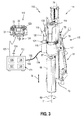
- eine dritte Ausführungsform eines erfindungsgemäßen Gerätesystems, das als Kernbohrsystem mit einer Fernbedienung, einem Elektronikaggregat, einer motorischen Vorschubeinheit und einem Bohrkopf ausgebildet ist;
- FIG. 4
- das Gerätesystem der
FIG. 1 mit einer Sicherheitseinheit, die eine eindeutige Zuordnung der Systemkomponenten durchführt; - FIGN. 5A, B
- den Ablauf des erfindungsgemäßen Verfahrens zur eindeutigen Zuordnung mit Hilfe der Sicherheitseinheit; und
- FIG. 6
- eine vierte Ausführungsform eines erfindungsgemäßen Gerätesystems, das als Kernbohrsystem mit einer Fernbedienung, einem ersten Elektronikaggregat, einer motorischen Vorschubeinheit, einem zweiten Elektronikaggregat und einem Bohrkopf ausgebildet ist.
- FIG. 1
- a first embodiment of a device system according to the invention, which is designed as a wall saw system with a remote control, an electronic unit and a wall saw;
- FIGS. 2A, B
- A second embodiment of a core drilling system designed according to the invention device system with a remote control, a motorized feed unit and a drill head (
FIG. 2A ) and the structure of the drill head and the motor feed unit in a schematic representation (FIG. 2 B ); - FIG. 3
- a third embodiment of a device system according to the invention, which is designed as a core drilling system with a remote control, an electronic unit, a motorized feed unit and a drill head;
- FIG. 4
- the device system of
FIG. 1 with a security unit that performs an unambiguous assignment of the system components; - FIGS. 5A, B
- the sequence of the inventive method for unambiguous assignment by means of the security unit; and
- FIG. 6
- a fourth embodiment of a device system according to the invention, which is designed as a core drilling system with a remote control, a first electronic unit, a motor feed unit, a second electronic unit and a drill head.
Das Werkzeuggerät ist als Wandsäge 12 ausgebildet und umfasst eine als Sägekopf 15 ausgebildete Bearbeitungseinheit und eine motorische Vorschubeinheit 16. Der Sägekopf 15 umfasst ein als Sägeblatt 17 ausgebildetes Bearbeitungswerkzeug, das an einem Sägearm 18 befestigt ist und von einem Antriebsmotor 19 um eine Drehachse 21 angetrieben wird. Zum Schutz des Bedieners kann das Sägeblatt 17 von einem Sägeblattschutz umgeben sein, der mittels eines Blattschutzhalters am Sägearm 18 befestigt wird. Der Sägearm 18 ist von einem Schwenkmotor 22 um eine Schwenkachse 23 schwenkbar ausgebildet. Der Schwenkwinkel des Sägearms 18 bestimmt mit dem Sägeblattdurchmesser des Sägeblattes 17, wie tief das Sägeblatt 17 in ein zu bearbeitendes Werkstück 24 eintaucht. Der Antriebsmotor 19 und der Schwenkmotor 22 sind in einem Gerätegehäuse 25 angeordnet. Die motorische Vorschubeinheit 16 umfasst einen Führungsschlitten 26 und einen Vorschubmotor 27, der ebenfalls im Gerätegehäuse 25 angeordnet ist. Der Sägekopf 15 ist auf dem Führungsschlitten 26 befestigt und über den Vorschubmotor 27 entlang der Führungsschiene 11 parallel zu einer Vorschubrichtung 28 (Doppelpfeil) verschiebbar ausgebildet.The tool device is designed as a wall saw 12 and comprises a
Die Fernbedienung 14 umfasst ein Gerätegehäuse 31, eine Eingabeeinrichtung 32, eine Anzeigeeinrichtung 33 und eine erste Kontrolleinheit 34, die im Inneren des Gerätegehäuses 31 angeordnet ist. Die erste Kontrolleinheit 34 wandelt die Eingaben über die Eingabeeinrichtung 32 in Steuerbefehle und Daten um, die über eine erste Kommunikationsverbindung an das Elektronikaggregat 13 übermittelt werden. Die erste Kommunikationsverbindung ist wahlweise als draht- und kabellose Kommunikationsverbindung 35 oder als erste Kabelverbindung 36 ausgebildet. Die erste Kabelverbindung 36 wird vor allem eingesetzt, wenn eine draht- und kabellose Kommunikation aus Sicherheitsgründen untersagt ist, wie beispielsweise in Krankenhäusern und auf Flughäfen, oder wenn Störquellen die draht- und kabellose Kommunikation behindern. Außerdem wird die erste Kabelverbindung 36 genutzt, um die Fernbedienung 14, das Elektronikaggregat 13 und die Wandsäge 12 mit Hilfe des erfindungsgemäßen Verfahrens zur eindeutigen Zuordnung einander eindeutig zuzuordnen. Die draht- und kabellose Kommunikationsverbindung ist im Ausführungsbeispiel als Funkverbindung 35 ausgebildet, die zwischen einer ersten Funkeinheit 37 an der Fernbedienung 14 und einer zweiten Funkeinheit 38 am Werkzeuggerät 12 entsteht. Alternativ kann die draht- und kabellose Kommunikationsverbindung 35 in Form einer Infrarot-, Bluetooth-, WLAN- oder Wi-Fi-Verbindung ausgebildet sein; neben den aufgeführten, draht- und kabellosen Verbindungstechnologien eignen sich sämtliche bereits bekannten und zukünftigen draht- und kabellosen Verbindungstechnologien zur Datenübertragung.The
Das Elektronikaggregat 13 umfasst eine erste Elektronikeinheit 41, die den Antriebsmotor 19 elektrisch versorgt, und ein erstes Steuerelement 42, das den Antriebsmotor 19 steuert, eine zweite Elektronikeinheit 43, die den Schwenkmotor 22 elektrisch versorgt, und ein zweites Steuerelement 44, das den Schwenkmotor 22 steuert, sowie eine dritte Elektronikeinheit 45, die den Vorschubmotor 27 elektrisch versorgt, und ein drittes Steuerelement 46, das den Vorschubmotor 27 steuert. Das erste, zweite und dritte Steuerelement 42, 44, 46 bilden gemeinsam eine zweite Kontrolleinheit 47. Das Elektronikaggregat 13 ist über eine zweite Kommunikationsverbindung 48 mit der Wandsäge 12 verbunden. Die zweite Kommunikationsverbindung ist im Ausführungsbeispiel als zweite Kabelverbindung 48 ausgebildet. Die elektrischen Versorgungsleitungen zwischen dem Elektronikaggregat 13 und der Wandsäge 12 sind in einem separaten Versorgungskabel 49 untergebracht. Alternativ können die Daten- und Steuerleitungen der zweiten Kommunikationsverbindung und die elektrischen Versorgungsleitungen des Versorgungskabels in einem gemeinsamen Verbindungskabel integriert sein.The
Die Bearbeitungseinheit ist als Bohrkopf 64 ausgebildet und umfasst ein als Bohrkrone 66 ausgebildetes Bearbeitungswerkzeug, das auf einer Antriebswelle 67 angeordnet ist und von einer Antriebseinrichtung 68 in einer Drehrichtung 69 um eine Drehachse 71 angetrieben wird. Unter dem Begriff "Antriebseinrichtung" werden sämtliche Antriebskomponenten für die Bohrkrone 66, mit Ausnahme der Antriebswelle 67, zusammengefasst. Die Antriebseinrichtung 68 ist in einem Gerätegehäuse 72 des Bohrkopfes 64 angeordnet.The processing unit is embodied as a
Der Geräteständer 61 besteht aus einer Grundplatte 73, die an einem Untergrund befestigt wird, und einer Führungsschiene 74, die mit der Grundplatte 73 verbunden ist. Der Bohrkopf 64 ist über einen Führungsschlitten 75 am Geräteständer 61 angeordnet und mittels der Vorschubvorrichtung 65 entlang der Führungsschiene 74 parallel zu einer Vorschubrichtung 76, die parallel zur Drehachse 71 verläuft, verschiebbar. Die Vorschubvorrichtung 65 umfasst eine motorische Vorschubeinheit 77 und eine, als Handrad ausgebildete, manuelle Vorschubeinheit 78. Der Bohrkopf 64 kann wahlweise mit der motorischen Vorschubeinheit 77 oder der manuellen Vorschubeinheit 78 entlang der Führungsschiene 74 des Geräteständers 61 verfahren werden.The device stand 61 consists of a
Die Fernbedienung 63 des Kernbohrsystems 60 ist analog zur Fernbedienung 14 des Wandsägesystems 10 aus dem Gerätegehäuse 31, der Eingabeeinrichtung 32, der Anzeigeeinrichtung 33 und einer ersten Kontrolleinheit 81 aufgebaut. Die erste Kontrolleinheit 81 der Fernbedienung 63 ist über eine erste Kommunikationsverbindung mit dem Bohrkopf 64 verbunden. Die erste Kommunikationsverbindung ist wahlweise als draht- und kabellose Kommunikationsverbindung 82 oder als erste Kabelverbindung 83 ausgebildet. Die draht- und kabellose Kommunikationsverbindung ist im Ausführungsbeispiel als Funkverbindung 82 ausgebildet, die zwischen einer ersten Funkeinheit 84 an der Fernbedienung 63 und einer zweiten Funkeinheit 85 an der motorischen Vorschubeinheit 77 entsteht.The
Die motorische Vorschubeinheit 77 ist über eine zweite Kommunikationsverbindung 86 mit dem Bohrkopf 64 verbunden, wobei die zweite Kommunikationsverbindung im Ausführungsbeispiel als zweite Kabelverbindung 86 ausgebildet ist. Im Ausführungsbeispiel der
Die motorische Vorschubeinheit 77 umfasst einen Vorschubmotor 91, eine Getriebeeinrichtung 92, eine Elektronikeinheit 93 zur elektrischen Versorgung des Vorschubmotors 91 und eine Kontrolleinheit 94 zur Steuerung des Vorschubmotors 91. Der Vorschubmotor 91, die Getriebeeinrichtung 92, die Elektronikeinheit 93 und die Kontrolleinheit 94 sind in einem Gerätegehäuse 95 der motorischen Vorschubeinheit 77 angeordnet.The
Die Antriebseinrichtung 68 umfasst einen Antriebsmotor 96, eine weitere Getriebeeinrichtung 97, eine weitere Elektronikeinheit 98 zur elektrischen Versorgung des Antriebsmotors 96 und eine weitere Kontrolleinheit 99 zur Steuerung des Antriebsmotors 96. Die Antriebswelle 67 wird vom Antriebsmotor 96 und der weiteren Getriebeeinrichtung 97 um die Drehachse 71 angetrieben, wobei die weitere Getriebeeinrichtung 97 zwischen dem Antriebsmotor 96 und der Antriebswelle 67 angeordnet ist. Der Antriebsmotor 96, die weitere Getriebeeinrichtung 97, die weitere Elektronikeinheit 98 und die weitere Kontrolleinheit 99 sind im Gerätegehäuse 72 des Bohrkopfes 64 angeordnet.The
Für das erfindungsgemäße Verfahren zur eindeutigen Zuordnung bilden die Fernbedienung 63 die erste Systemkomponente, die motorische Vorschubeinheit 77 die zweite Systemkomponente und der Bohrkopf 64 die dritte Systemkomponente des Kernbohrsystems 60. Jede Systemkomponente 63, 77, 64 des Kernbohrsystems 60 weist eine Kontrolleinheit und ein Gerätegehäuse auf. Zur Unterscheidung der Kontrolleinheiten der Fernbedienung 63, der motorischen Vorschubeinheit 77 und des Bohrkopfes 64 werden die Kontrolleinheit 71 der Fernbedienung 63 als erste Kontrolleinheit, die Kontrolleinheit 94 der motorischen Vorschubeinheit 77 als zweite Kontrolleinheit und die Kontrolleinheit 99 des Bohrkopfes 64 als dritte Kontrolleinheit bezeichnet. Außerdem werden das Gerätegehäuse 31 der Fernbedienung 63 als erstes Gerätegehäuse, das Gerätegehäuse 95 der motorischen Vorschubeinheit 77 als zweites Gerätegehäuse und das Gerätegehäuse 72 des Bohrkopfes 64 als drittes Gerätegehäuse bezeichnet.For the unique allocation method according to the invention, the
Die Bearbeitungseinheit ist als Bohrkopf 111 ausgebildet und umfasst das als Bohrkrone 66 ausgebildete Bearbeitungswerkzeug, das auf der Antriebswelle 67 angeordnet ist und von einem Antriebsmotor 116 in der Drehrichtung 69 um eine Drehachse 71 angetrieben wird. Der in
Der Bohrkopf 114 ist über den Führungsschlitten 75 am Geräteständer 61 angeordnet und mittels der Vorschubvorrichtung 115 entlang der Führungsschiene 74 in der Vorschubrichtung 76 verschiebbar. Die Vorschubvorrichtung 115 umfasst eine motorische Vorschubeinheit 118 und die, als Handrad ausgebildete, manuelle Vorschubeinheit 78. Der Bohrkopf 114 kann wahlweise mit der motorischen Vorschubeinheit 118 oder der manuellen Vorschubeinheit 78 entlang der Führungsschiene 74 verfahren werden. Die motorische Vorschubeinheit 118 umfasst einen Vorschubmotor 121, der in einem Gerätegehäuse 122 angeordnet ist; sämtliche Elektronikkomponenten zur Steuerung und Versorgung des Vorschubmotors 121 sind im Elektronikaggregat 112 untergebracht.The
Die Fernbedienung 113 des Kernbohrsystems 110 ist analog zu den Fernbedienungen 14, 63 des Wandsägesystems 10 der
Das Elektronikaggregat 112 umfasst eine erste Elektronikeinheit 126, die den Antriebsmotor 116 elektrisch versorgt, und ein erstes Steuerelement 127, das den Antriebsmotor 116 steuert, sowie eine zweite Elektronikeinheit 128, die den Vorschubmotor 121 elektrisch versorgt, und ein zweites Steuerelement 129, das den Vorschubmotor 121 steuert. Das erste und zweite Steuerelement 127, 129 bilden gemeinsam eine zweite Kontrolleinheit 131. Das Elektronikaggregat 112 ist über eine zweite Kommunikationsverbindung mit der motorischen Vorschubeinheit 118 verbunden. Dabei ist die zweite Kommunikationsverbindung im Ausführungsbeispiel als zweite Kabelverbindung 132 ausgebildet, die mit elektrischen Versorgungsleitungen 133 in ein Verbindungskabel 134 integriert ist. Die motorische Vorschubeinheit 118 ist über eine dritte Kommunikationsverbindung mit dem Bohrkopf 114 verbunden. Die dritte Kommunikationsverbindung ist im Ausführungsbeispiel als dritte Kabelverbindung 135 ausgebildet.The
Für das erfindungsgemäße Verfahren zur eindeutigen Zuordnung bilden die Fernbedienung 113 die erste Systemkomponente, das Elektronikaggregat 112 die zweite Systemkomponente, die motorische Vorschubeinheit 118 die dritte Systemkomponente und der Bohrkopf 114 die vierte Systemkomponente des Kernbohrsystems 110.For the unique allocation method according to the invention, the
Die eindeutige Zuordnung der drei Systemkomponenten 14, 13, 12 des Gerätesystems 10 erfolgt mittels einer Sicherheitseinheit 141. Die Fernbedienung 14 stellt die erste Systemkomponente, das Elektronikaggregat 13 die zweite Systemkomponente und das Werkzeuggerät 12 die dritte Systemkomponente des Gerätesystems 10 dar. Jede Systemkomponente 14, 13, 12 ist durch einen eindeutigen Identifikationscode gekennzeichnet, die Fernbedienung 14 durch einen ersten Identifikationscode ID-1, das Elektronikaggregat 13 durch einen zweiten Identifikationscode ID-2 und das Werkzeuggerät 12 durch einen dritten Identifikationscode ID-3. The unambiguous assignment of the three
Die Sicherheitseinheit 141 umfasst einen ersten Transceiver 142, einen zweiten Transceiver 143 und einen dritten Transceiver 144 sowie ein erstes Speicherelement 145, ein zweites Speicherelement 146 und ein drittes Speicherelement 147. Der erste Transceiver 142 und das erste Speicherelement 145 sind in der Fernbedienung 14 angeordnet und bilden ein erstes Teil 151 der Sicherheitseinheit 141, der zweite Transceiver 143 und das zweite Speicherelement 146 sind im Elektronikaggregat 13 angeordnet und bilden ein zweites Teil 152 der Sicherheitseinheit 141 und der dritte Transceiver 144 und das dritte Speicherelement 147 sind im Werkzeuggerät 12 angeordnet und bilden ein drittes Teil 153 der Sicherheitseinheit 141. Das erste, zweite und dritte Teil 151, 152, 153 bilden gemeinsam die Sicherheitseinheit 141.The
In jedem Speicherelement werden zumindest die Identifikationscodes der direkt verbundenen Systemkomponenten als Vergleichscodes VCi-j gespeichert. Die Vergleichscodes VCi-j weisen zwei Indices auf, wobei der erste Index i, i = 1 bis 3 die speichernde Systemkomponente und der zweite Index j, j = 1 bis 3 die empfangende Systemkomponente kennzeichnet. Die Fernbedienung 14 ist über die erste Kabelverbindung 36 direkt mit dem Elektronikaggregat 13 verbunden und speichert zumindest den zweiten Identifikationscode ID-2 des Elektronikaggregates 13 als zweiten Vergleichscode VC1-2. Die Wandsäge 12 ist über die zweite Kabelverbindung 48 direkt mit dem Elektronikaggregat 13 verbunden und speichert zumindest den zweiten Identifikationscode ID-2 des Elektronikaggregates 13 als zweiten Vergleichscode VC3-2. Das Elektronikaggregat 13 ist direkt mit der Fernbedienung 14 und der Wandsäge 12 verbunden und speichert daher den ersten Identifikationscode ID-1 der Fernbedienung 14 als ersten Vergleichscode VC2 -1 und den dritten Identifikationscode ID-3 der Wandsäge 12 als dritten Vergleichscode VC2-3. In each memory element at least the identification codes of the directly connected system components are stored as comparison codes VC i -j . The comparison codes VC i -j have two indices, wherein the first index i, i = 1 to 3 indicates the storing system component and the second index j, j = 1 to 3 identifies the receiving system component. The
In einer Weiterentwicklung speichern die Systemkomponenten 14, 13, 12 nicht nur die Identifikationscodes der direkt verbundenen Systemkomponenten als Vergleichscodes, sondern die Identifikationscodes aller Systemkomponenten 14, 13, 12 des Gerätesystems 10 werden als Vergleichscodes gespeichert. Die Speicherelemente 145, 146, 147 weisen im Ausführungsbeispiel jeweils drei Speicherstellen zum Speichern von Identifikationscodes auf. Im ersten Speicherelement 145 wird neben dem zweiten Vergleichscode VC1-2 der Fernbedienung 14 der dritte Identifikationscode ID-3 des Werkzeuggerätes 12 als dritter Vergleichscode VC1-3 der Fernbedienung 14 gespeichert und im dritten Speicherelement 147 wird neben dem zweiten Vergleichscode VC3-2 des Werkzeuggerätes 12 der erste Identifikations-code ID-1 der Fernbedienung 14 als erster Vergleichscode VC3-1 des Werkzeuggerätes 12 gespeichert. Der eigene Identifikationscode ID-1, ID-2, ID-3 einer Systemkomponente 14, 13, 12 kann wie im Ausführungsbeispiel in einer weiteren Speicherstelle des eigenen Speicherelementes 145, 146, 147 gespeichert sein oder an einer anderen Stelle in der Kontrolleinheit.In a further development, the
Der erste Transceiver 142 übermittelt den ersten Identifikationscode ID-1 der Fernbedienung 14 über die erste Kabelverbindung 36 an den zweiten Transceiver 143, der den ersten Identifikationscode ID-1 als ersten Vergleichscode VC2-1 im zweiten Speicherelement 146 speichert. Der zweite Transceiver 143 übermittelt den ersten Identifikationscode ID-1 der Fernbedienung 14 und den eigenen, zweiten Identifikationscode ID-2 des Elektronikaggregates 13 über die zweite Kabelverbindung 48 an den dritten Transceiver 144, der den ersten Identifikationscode ID-1 als ersten Vergleichscode VC3-1 der dritten Systemkomponente und den zweiten Identifikationscode ID-2 als zweiten Vergleichscode VC3-2 der dritten Systemkomponente im dritten Speicherelement 147 speichert. Der dritte Transceiver 144 übermittelt den dritten Identifikationscode ID-3 des Werkzeuggerätes 12 über die zweite Kabelverbindung 48 an den zweiten Transceiver 143, der den dritten Identifikationscode ID-3 als dritten Vergleichscode VC2-3 der zweiten Systemkomponente im zweiten Speicherelement 146 speichert. Der zweite Transceiver 143 übermittelt den zweiten Identifikationscode ID-2 des Elektronikaggregates 13 und den dritten Identifikationscode ID-3 des Werkzeuggerätes 12 über die erste Kabelverbindung 36 an den ersten Transceiver 142, der den zweiten Identifikationscode ID-2 als zweiten Vergleichscode VC1-2 der ersten Systemkomponente und den dritten Identifikationscode ID-3 als dritten Vergleichscode VC1-3 der ersten Systemkomponente im ersten Speicherelement 145 speichert.The
Nach Abschluss des erfindungsgemäßen Verfahrens sind in jedem Speicherelement 145, 146, 147 die Identifikationscodes der Systemkomponenten 14, 13, 12 des Gerätesystems 10 gespeichert. Um sicherzustellen, dass während des Betriebs nur die einander eindeutig zugeordneten Systemkomponenten 14, 13, 12 miteinander kommunizieren, werden bei der Datenübertragung die Identifikationscodes regelmäßig übertragen und von den Transceivern 142, 143, 144 der Systemkomponenten mit den gespeicherten Vergleichscodes verglichen. Steuerbefehle und Daten, die beispielsweise von der Fernbedienung 14 über die erste Kommunikationsverbindung 35 übertragen werden, werden nur ausgeführt, wenn der von der Fernbedienung 14 übertragene erste Identifikationscode ID-1 mit dem, im zweiten Speicherelement 146 gespeicherten, ersten Vergleichscode VC2-1 der zweiten Systemkomponente übereinstimmt.After completion of the method according to the invention, the identification codes of the
In einer Weiterentwicklung des erfindungsgemäßen Verfahrens werden nicht nur die Identifikationscodes der Systemkomponenten 14, 13, 12 des Gerätesystems 10 übertragen, sondern zusätzlich werden weitere Informationen über die Systemkomponenten des Gerätesystems 10 übertragen. Zu diesen weiteren Informationen gehören beispielsweise Gerätetypen und gerätespezifische Kenngrößen. Wenn eine Fernbedienung 14 verschiedene Werkzeuggeräte bedienen kann, müssen verschiedene Steuerungsverfahren in der Kontrolleinheit der Fernbedienung gespeichert sein. In der Praxis ist es üblich, dass eine Fernbedienung beispielsweise eine Diamantwandsäge und eine Diamantseilsäge steuern kann. Für eine gesteuerte Bearbeitung sind gerätespezifische Kenngrößen erforderlich, die der Fernbedienung übermittelt werden müssen. Die Eingabe dieser Kenngrößen kann vom Bediener vorgenommen werden oder die Kenngrößen können in der Kontrolleinheit jeder Systemkomponente gespeichert und bei der Zuordnung der Systemkomponenten übertragen werden. Wenn die Fernbedienung 14 mit einer Wandsäge 12 verbunden wird, werden in der Fernbedienung 14 nur die Steuerungsverfahren angezeigt, die für den vorliegenden Gerätetyp der Wandsäge 12 geeignet sind. Dem Bediener werden keine Steuerungsverfahren angezeigt, die für die Wandsäge 12 ungeeignet sind.In a further development of the method according to the invention not only the identification codes of the
Die motorische Vorschubeinheit 163 und der Bohrkopf 165 des Kernbohrsystems 160 entsprechen im Aufbau den Systemkomponenten des Kernbohrsystems 110 der
Die Fernbedienung 161 ist über eine erste Kommunikationsverbindung mit dem ersten Elektronikaggregat 162 verbunden, wobei die erste Kommunikationsverbindung als draht- und kabellose Kommunikationsverbindung 166 oder als erste Kabelverbindung 167 ausgebildet ist. Das erste Elektronikaggregat 162 ist über eine zweite Kommunikationsverbindung 168 mit der motorischen Vorschubeinheit 163 und über eine dritte Kommunikationsverbindung 169 mit dem zweiten Elektronikaggregat 164 verbunden. Die zweite Kommunikationsverbindung ist als zweite Kabelverbindung 168 ausgebildet und die dritte Kommunikationsverbindung als dritte Kabelverbindung 169. Das zweite Elektronikaggregat 164 ist über eine vierte Kommunikationsverbindung, die als vierte Kabelverbindung 171 ausgebildet ist, mit dem Bohrkopf 165 verbunden.The
Die elektrische Versorgung der motorischen Vorschubeinheit 163 erfolgt über ein erstes Versorgungskabel 172, das das erste Elektronikaggregat 162 mit der motorischen Vorschubeinheit 163 verbindet. Dabei können die zweite Kabelverbindung 168 und das erste Versorgungskabel 172, wie in
Claims (21)
Priority Applications (5)
| Application Number | Priority Date | Filing Date | Title |
|---|---|---|---|
| EP14200010.8A EP3038073A1 (en) | 2014-12-23 | 2014-12-23 | Method for the unambiguous allocation of a remote control to a device system |
| US15/538,553 US20170345289A1 (en) | 2014-12-23 | 2015-12-22 | Method for the unique allocation of a remote control to a device system |
| EP15817347.6A EP3238195B1 (en) | 2014-12-23 | 2015-12-22 | Method for the unambiguous allocation of a remote control to a device system |
| PCT/EP2015/080951 WO2016102552A1 (en) | 2014-12-23 | 2015-12-22 | Method for unique allocation of a remote control to an equipment system |
| US16/059,143 US20190005808A1 (en) | 2014-12-23 | 2018-08-09 | Method for the unique allocation of a remote control to a device system |
Applications Claiming Priority (1)
| Application Number | Priority Date | Filing Date | Title |
|---|---|---|---|
| EP14200010.8A EP3038073A1 (en) | 2014-12-23 | 2014-12-23 | Method for the unambiguous allocation of a remote control to a device system |
Publications (1)
| Publication Number | Publication Date |
|---|---|
| EP3038073A1 true EP3038073A1 (en) | 2016-06-29 |
Family
ID=52282517
Family Applications (2)
| Application Number | Title | Priority Date | Filing Date |
|---|---|---|---|
| EP14200010.8A Withdrawn EP3038073A1 (en) | 2014-12-23 | 2014-12-23 | Method for the unambiguous allocation of a remote control to a device system |
| EP15817347.6A Active EP3238195B1 (en) | 2014-12-23 | 2015-12-22 | Method for the unambiguous allocation of a remote control to a device system |
Family Applications After (1)
| Application Number | Title | Priority Date | Filing Date |
|---|---|---|---|
| EP15817347.6A Active EP3238195B1 (en) | 2014-12-23 | 2015-12-22 | Method for the unambiguous allocation of a remote control to a device system |
Country Status (3)
| Country | Link |
|---|---|
| US (2) | US20170345289A1 (en) |
| EP (2) | EP3038073A1 (en) |
| WO (1) | WO2016102552A1 (en) |
Cited By (2)
| Publication number | Priority date | Publication date | Assignee | Title |
|---|---|---|---|---|
| EP3404635A1 (en) * | 2017-05-19 | 2018-11-21 | HOMAG GmbH | Remote control apparatus |
| WO2021228644A1 (en) * | 2020-05-12 | 2021-11-18 | Black & Decker Inc. | A power tool |
Families Citing this family (1)
| Publication number | Priority date | Publication date | Assignee | Title |
|---|---|---|---|---|
| EP2993015A1 (en) * | 2014-09-08 | 2016-03-09 | HILTI Aktiengesellschaft | Method for controlling a wall saw system when creating a separating cut |
Citations (3)
| Publication number | Priority date | Publication date | Assignee | Title |
|---|---|---|---|---|
| US20090045970A1 (en) * | 2007-08-16 | 2009-02-19 | Sony Corporation | Remote control system, receiving apparatus, and electronic device |
| US20110056716A1 (en) | 2008-02-29 | 2011-03-10 | Husqvarna Ab | Electric saw communication |
| EP2424268A1 (en) * | 2009-06-15 | 2012-02-29 | Panasonic Corporation | Remote control system, television set and pairing method |
Family Cites Families (7)
| Publication number | Priority date | Publication date | Assignee | Title |
|---|---|---|---|---|
| FR2603218B1 (en) * | 1986-09-01 | 1994-03-11 | Meseltron Sa | WIRELESS DEVICE FOR CONTROLLING THE FEED SPEED OF A TOOL TO A WORKPIECE. |
| JP3465021B2 (en) * | 1997-02-14 | 2003-11-10 | エヌティーエンジニアリング株式会社 | Work machine and communication method thereof |
| WO2006000571A1 (en) * | 2004-06-24 | 2006-01-05 | Abb Ab | Industrial robot system with a portable operator control device |
| EP2569120B1 (en) * | 2010-04-16 | 2015-01-21 | Husqvarna AB | A drilling device with a controller for the feeding unit. |
| DE102012221997A1 (en) * | 2012-05-25 | 2013-11-28 | Robert Bosch Gmbh | power tool |
| WO2014015072A2 (en) * | 2012-07-17 | 2014-01-23 | Milwaukee Electric Tools Corporation | Universal protocol for power tools |
| US9773409B1 (en) * | 2014-09-30 | 2017-09-26 | Apple Inc. | Automatically configuring a remote control for a device |
-
2014
- 2014-12-23 EP EP14200010.8A patent/EP3038073A1/en not_active Withdrawn
-
2015
- 2015-12-22 EP EP15817347.6A patent/EP3238195B1/en active Active
- 2015-12-22 WO PCT/EP2015/080951 patent/WO2016102552A1/en active Application Filing
- 2015-12-22 US US15/538,553 patent/US20170345289A1/en not_active Abandoned
-
2018
- 2018-08-09 US US16/059,143 patent/US20190005808A1/en not_active Abandoned
Patent Citations (3)
| Publication number | Priority date | Publication date | Assignee | Title |
|---|---|---|---|---|
| US20090045970A1 (en) * | 2007-08-16 | 2009-02-19 | Sony Corporation | Remote control system, receiving apparatus, and electronic device |
| US20110056716A1 (en) | 2008-02-29 | 2011-03-10 | Husqvarna Ab | Electric saw communication |
| EP2424268A1 (en) * | 2009-06-15 | 2012-02-29 | Panasonic Corporation | Remote control system, television set and pairing method |
Cited By (2)
| Publication number | Priority date | Publication date | Assignee | Title |
|---|---|---|---|---|
| EP3404635A1 (en) * | 2017-05-19 | 2018-11-21 | HOMAG GmbH | Remote control apparatus |
| WO2021228644A1 (en) * | 2020-05-12 | 2021-11-18 | Black & Decker Inc. | A power tool |
Also Published As
| Publication number | Publication date |
|---|---|
| US20170345289A1 (en) | 2017-11-30 |
| WO2016102552A1 (en) | 2016-06-30 |
| US20190005808A1 (en) | 2019-01-03 |
| EP3238195B1 (en) | 2020-10-07 |
| EP3238195A1 (en) | 2017-11-01 |
Similar Documents
| Publication | Publication Date | Title |
|---|---|---|
| EP0243811B1 (en) | Control device for rotary printing machines | |
| EP1535247B1 (en) | System for accident prevention | |
| EP3238195B1 (en) | Method for the unambiguous allocation of a remote control to a device system | |
| DE202006014606U1 (en) | Cordless electric tool, especially screwdriver, has transmitter with at least one module adapter reversibly mounted on the tool and a replaceable radio module | |
| DE102016121145A1 (en) | Selection device and network system for selecting electric motor systems | |
| EP2956268B1 (en) | Method of controlling a tool system with a tool and a motorised feed device | |
| DE102012017376A1 (en) | Electrical propelled tool i.e. rechargeable battery-claimant screw jack, has tool components provided with power supply unit that enables data communication unit to generate power using inductive coupling | |
| DE102015226734A1 (en) | Industrial device and portable device | |
| EP3339996A1 (en) | Device system comprising a tool or measuring device | |
| EP3441037A1 (en) | Surgical robot system and access control method of a surgical instrument designed to be inserted in a surgical robot system | |
| EP3191901A1 (en) | Method for monitoring the functional capability of a device system | |
| EP3084537A1 (en) | Method for controlling a device system, which comprises a tool device and a motorized advancing apparatus | |
| EP3476516B1 (en) | Soldering device | |
| EP3191277A1 (en) | Device system with a radio link | |
| EP2014409A1 (en) | Multi-axis swivel head with integrated controller and coordinate measuring machine with such a multi-axis swivel head | |
| DE102017119270B4 (en) | Lathe and a method for controlling a lathe | |
| EP3205456B1 (en) | Transport device for transporting output tools at the tool, tool and method for communication between a tool and a transport device | |
| DE2804011A1 (en) | Machine tool work unit changeover control - uses data carriers feeding instructions to adjustment unit to vary locations of positioning components | |
| EP2151726A2 (en) | Programmable machine, handheld programming device and method for programming a programmable machine | |
| DE60205774T2 (en) | IDENTIFICATION PROCESS AND SYSTEM | |
| DE102007003003B4 (en) | System and base station for transporting data | |
| EP3456486A1 (en) | Redundant diverse collision monitoring | |
| DE102013202444A1 (en) | Device for remote control of a tool device | |
| WO2017215999A1 (en) | Movement-dependent transmission of data between a hand-held machine tool and an external unit | |
| DE102018007324A1 (en) | Apparatus and method for attaching a bore to a motor vehicle part |
Legal Events
| Date | Code | Title | Description |
|---|---|---|---|
| PUAI | Public reference made under article 153(3) epc to a published international application that has entered the european phase |
Free format text: ORIGINAL CODE: 0009012 |
|
| AK | Designated contracting states |
Kind code of ref document: A1 Designated state(s): AL AT BE BG CH CY CZ DE DK EE ES FI FR GB GR HR HU IE IS IT LI LT LU LV MC MK MT NL NO PL PT RO RS SE SI SK SM TR |
|
| AX | Request for extension of the european patent |
Extension state: BA ME |
|
| STAA | Information on the status of an ep patent application or granted ep patent |
Free format text: STATUS: THE APPLICATION IS DEEMED TO BE WITHDRAWN |
|
| 18D | Application deemed to be withdrawn |
Effective date: 20170103 |