EP3035556B1 - Method and apparatus for transmitting common signal in hybrid beamforming - Google Patents
Method and apparatus for transmitting common signal in hybrid beamforming Download PDFInfo
- Publication number
- EP3035556B1 EP3035556B1 EP15193057.5A EP15193057A EP3035556B1 EP 3035556 B1 EP3035556 B1 EP 3035556B1 EP 15193057 A EP15193057 A EP 15193057A EP 3035556 B1 EP3035556 B1 EP 3035556B1
- Authority
- EP
- European Patent Office
- Prior art keywords
- common signal
- analog
- digital
- beamforming
- beamformer
- Prior art date
- Legal status (The legal status is an assumption and is not a legal conclusion. Google has not performed a legal analysis and makes no representation as to the accuracy of the status listed.)
- Active
Links
- 238000000034 method Methods 0.000 title claims description 41
- 125000004122 cyclic group Chemical group 0.000 claims description 62
- 238000006243 chemical reaction Methods 0.000 claims description 5
- 238000009826 distribution Methods 0.000 claims description 5
- 230000004044 response Effects 0.000 claims description 5
- 238000010586 diagram Methods 0.000 description 34
- 238000001228 spectrum Methods 0.000 description 23
- 238000005516 engineering process Methods 0.000 description 8
- 238000012545 processing Methods 0.000 description 8
- 230000005540 biological transmission Effects 0.000 description 6
- 238000004891 communication Methods 0.000 description 5
- 238000011160 research Methods 0.000 description 4
- 238000010295 mobile communication Methods 0.000 description 3
- 238000004088 simulation Methods 0.000 description 2
- 238000011161 development Methods 0.000 description 1
- 238000005315 distribution function Methods 0.000 description 1
- 230000007774 longterm Effects 0.000 description 1
- 238000009828 non-uniform distribution Methods 0.000 description 1
- 230000003595 spectral effect Effects 0.000 description 1
Images


Classifications
-
- H—ELECTRICITY
- H04—ELECTRIC COMMUNICATION TECHNIQUE
- H04B—TRANSMISSION
- H04B7/00—Radio transmission systems, i.e. using radiation field
- H04B7/02—Diversity systems; Multi-antenna system, i.e. transmission or reception using multiple antennas
- H04B7/04—Diversity systems; Multi-antenna system, i.e. transmission or reception using multiple antennas using two or more spaced independent antennas
- H04B7/06—Diversity systems; Multi-antenna system, i.e. transmission or reception using multiple antennas using two or more spaced independent antennas at the transmitting station
- H04B7/0686—Hybrid systems, i.e. switching and simultaneous transmission
-
- H—ELECTRICITY
- H04—ELECTRIC COMMUNICATION TECHNIQUE
- H04B—TRANSMISSION
- H04B7/00—Radio transmission systems, i.e. using radiation field
- H04B7/02—Diversity systems; Multi-antenna system, i.e. transmission or reception using multiple antennas
- H04B7/04—Diversity systems; Multi-antenna system, i.e. transmission or reception using multiple antennas using two or more spaced independent antennas
- H04B7/0413—MIMO systems
- H04B7/0456—Selection of precoding matrices or codebooks, e.g. using matrices antenna weighting
-
- H—ELECTRICITY
- H04—ELECTRIC COMMUNICATION TECHNIQUE
- H04B—TRANSMISSION
- H04B7/00—Radio transmission systems, i.e. using radiation field
- H04B7/02—Diversity systems; Multi-antenna system, i.e. transmission or reception using multiple antennas
- H04B7/04—Diversity systems; Multi-antenna system, i.e. transmission or reception using multiple antennas using two or more spaced independent antennas
- H04B7/06—Diversity systems; Multi-antenna system, i.e. transmission or reception using multiple antennas using two or more spaced independent antennas at the transmitting station
- H04B7/0613—Diversity systems; Multi-antenna system, i.e. transmission or reception using multiple antennas using two or more spaced independent antennas at the transmitting station using simultaneous transmission
- H04B7/0615—Diversity systems; Multi-antenna system, i.e. transmission or reception using multiple antennas using two or more spaced independent antennas at the transmitting station using simultaneous transmission of weighted versions of same signal
- H04B7/0617—Diversity systems; Multi-antenna system, i.e. transmission or reception using multiple antennas using two or more spaced independent antennas at the transmitting station using simultaneous transmission of weighted versions of same signal for beam forming
-
- H—ELECTRICITY
- H04—ELECTRIC COMMUNICATION TECHNIQUE
- H04B—TRANSMISSION
- H04B7/00—Radio transmission systems, i.e. using radiation field
- H04B7/02—Diversity systems; Multi-antenna system, i.e. transmission or reception using multiple antennas
- H04B7/04—Diversity systems; Multi-antenna system, i.e. transmission or reception using multiple antennas using two or more spaced independent antennas
- H04B7/06—Diversity systems; Multi-antenna system, i.e. transmission or reception using multiple antennas using two or more spaced independent antennas at the transmitting station
- H04B7/0613—Diversity systems; Multi-antenna system, i.e. transmission or reception using multiple antennas using two or more spaced independent antennas at the transmitting station using simultaneous transmission
- H04B7/0667—Diversity systems; Multi-antenna system, i.e. transmission or reception using multiple antennas using two or more spaced independent antennas at the transmitting station using simultaneous transmission of delayed versions of same signal
- H04B7/0671—Diversity systems; Multi-antenna system, i.e. transmission or reception using multiple antennas using two or more spaced independent antennas at the transmitting station using simultaneous transmission of delayed versions of same signal using different delays between antennas
Definitions
- the present disclosure relates to wireless communication technologies, and more particularly to a method and apparatus for transmitting a common signal in hybrid beamforming and multi-user Multiple Input Multiple Output (MIMO).
- MIMO Multiple Input Multiple Output
- 5G should meet several key requirements, for example, 1) transmission rate is improved 10-100 times, experience rate to end users (UEs) is up to 1Gb/s, and user peak rate is up to and beyond 10Gb/s; 2) the density of connected devices is improved 10-100 times, up to millions per square kilometer.
- one method is to propose massive MIMO and use spectrum resources at high frequency, so as to further explore spatial dimensional radio resources and solve the problem about spectrum efficiency and power efficiency in future mobile communication.
- Additional features of massive MIMO wireless communication technologies include: deploying tens of or hundreds of antennas in the coverage of base station, and placing those antennas in a massive array. Multiple users distributed in the coverage of base station communicate with the base station simultaneously on a same time and frequency resource by taking advantage of spatial freedom provided by the massive antennas configured at the base station, which can improve the multiplexing capability of spectrum resources among multiple users, spectral efficiency of each user's link and capability to suppress the inter-cell interference, so that the overall efficiency of spectrum resources may be enhanced greatly. In addition, by using the diversity gain and array gain provided by the massive antennas configured at the base station, the power efficiency of the communication link between each user and the base station may be improved further.
- the wavelength of a high-frequency signal is short, so the high-frequency band is suitable for massive MIMO with densely deployed antenna elements. But the high-frequency signal tends to be more influenced by path loss, and a bottleneck caused by the significant increase of antenna number only at the base station occurs for the massive MIMO technologies. Thus, it can be seen that, massive MIMO is different from the current MIMO transmission technologies. It is required to research on the wireless transmission technologies which is feasible in the scenario of massive MIMO.
- hybrid beamforming for the user signal, a user-specific beamforming may be used to transmit signals to the corresponding user.
- common signal there are no corresponding transmission technologies available in the hybrid beamforming, so severe pathloss caused by using resources at a high-frequency band may reduce the coverage of the common signals.
- US 2014/050280A1 describes a station in a wireless communication system, which includes a processor circuitry configured to form at least a first plurality of data streams and a second plurality of data streams, and a digital precoder configured to receive the first plurality of data streams and the second plurality of data streams.
- the wireless station can further include a plurality of radio frequency (RF) beamforming chains connected to the digital precoder and configured to form at least one RF envelope.
- RF radio frequency
- US 2010/0238889 A1 describes an apparatus and method for operating a Codebook Subset Pattern (CSP) of a Base Station (BS) in a Multiple Input Multiple Output (MIMO) system.
- the method includes determining whether there is a CSP-updated BS among the BS and adjacent BSs, exchanging the updated CSP between cells if it is determined that there is a CSP-updated BS, and broadcasting the CSP of each cell acquired through the exchange thereby reducing an inter-cell interference in the MIMO system.
- CSP Codebook Subset Pattern
- MIMO Multiple Input Multiple Output
- Damman A. et al "Beamforming in combination with space-time diversity for broadband OFDM systems", Proceedings of IEEE International Conference on Communications - 28. April - 2. May 2002 - New York, NY, USA, IEEE, Piscataway, NJ, USA, Vol. 1, 28. April 2002, pages 165-171 , describe various beamforming scenarios with transmitter and/or receiver sided beamforming.
- Space-time diversity is obtained by cyclic delay diversity (CDD) in order to artificially shape the spectrum of the received signal.
- CDD cyclic delay diversity
- the present disclosure provides a method and apparatus for transmitting a common signal in hybrid beamforming to suppress the pathloss of high frequency signals and achieve an effective coverage area of the common signal in hybrid beamforming.
- the present disclosure provides a method for transmitting a common signal in hybrid beamforming, wherein the common signal is a signal transmitted in a common channel, and does not include user data, and the method comprises: acquiring a digital common signal for generating an analog common signal to be transmitted (901); acquiring a cyclic shift for each RF chain according to a principle of using different cyclic shifts for RF chains corresponding to adjacent beams and using a same cyclic shift for RF chains corresponding to non-adjacent beams, and generating a digital beamformer using the acquired cyclic shift (902); beamforming the digital common signal in each RF chain using the digital beamformer in digital baseband (903); acquiring the analog common signal to be transmitted (101, 502) by performing Inverse Fourier Transform and digital-to-analog conversion to the beamformed digital common signal; dividing codewords in a codebook for analog beamforming into at least two codeword groups (501) according to users' distribution; selecting different codeword groups for adjacent timeslots,
- the present disclosure provides an apparatus for transmitting a common signal in hybrid beamforming, wherein the common signal is a signal transmitted in a common channel, and does not include user data, and the apparatus comprises: a digital common signal acquiring module (1301), configured to acquire a digital common signal for generating the analog common signal to be transmitted; a digital beamformer obtaining module (1302), configured to acquire a cyclic shift for each RF chain according to a principle of using different cyclic shifts for RF chains corresponding to adjacent beams and using a same cyclic shift for RF chains corresponding to non-adjacent beams, and obtain a digital beamformer using the acquired cyclic shift; a digital beamforming module (1303), configured to beamform the digital common signal in each RF chain using the digital beamformer in digital baseband; an analog common signal acquiring module (401, 802), configured to acquire an analog common signal to be transmitted by performing Inverse Fourier Transform and digital-to-analog conversion to the beamformed digital common signal; a code
- the analog RF front-end selecting a different codeword for each RF chain from a codebook for analog beamforming and obtaining an analog beamformer; beamforming the analog common signal to be transmitted in each RF chain according to the analog beamformer, the pathloss of high frequency signals is well suppressed, and the effective coverage area of the common signal in hybrid beamforming is enhanced.
- each codeword group includes at least one codeword; selecting different codeword groups for adjacent timeslots, selecting a different codeword from the selected codeword group for each RF chain and obtaining an analog beamformer, the effective coverage area of the common signal in hybrid beamforming is further enhanced.
- the digital baseband back-end by at the digital baseband back-end, acquiring a cyclic shift for each RF chain according to a principle of using different cyclic shifts for RF chains corresponding to adjacent beams, and generating a digital beamformer using the acquired cyclic shift, so as to beamform the digital common signal in each RF chain using the digital beamformer in digital baseband, the effective coverage area and robustness of the common signal in hybrid beamforming are further enhanced.
- the hybrid beamforming refers to the joint operations of analog beamforming and digital beamforming.
- the analog beamforming means performing beamforming in an analog domain
- the digital beamforming means performing beamforming in a digital domain.
- the common signal refers to the signal transmitted in a common channel, including all the data except the user data.
- the common signal may be a Channel State Information-Reference Signal (CSI-RS), or a discovery signal (DS).
- CSI-RS Channel State Information-Reference Signal
- DS discovery signal
- the common signals are transmitted in beamforming; by considering the common signal are required to cover all the cell, the user-specific beamforming is not used for the common signal, but for each RF chain, different beamformers are selected from a codebook for analog beamforming , and the selected beamformers are used to beamform the analog common signal to be transmitted in different RF chains, such that, the common signal is transmitted in hybrid beamforming.
- Fig. 1 is a flow chart illustrating a method for transmitting a common signal in hybrid beamforming according to a first example of the present disclosure. As shown in Fig. 1 , the method is applied in a base station, and includes the following procedures.
- the base station acquires an analog common signal to be transmitted.
- the analog common signal to be transmitted may be obtained by performing digital-to-analog conversion (DAC) to a digital common signal.
- DAC digital-to-analog conversion
- Fig. 2 is a schematic diagram illustrating a method for processing the common signal in hybrid beamforming according to a first example of the present disclosure.
- the signal Sa is the analog common signal to be transmitted.
- the base station selects a different codeword for each RF chain from a codebook for analog beamforming and obtains an analog beamformer.
- Selecting a different codeword may enable the common signal to propagate along different directions.
- the codewords in the codebook for analog beamforming are generally configured by the antenna producer in advance. More codewords indicate high freedom and a relatively high cost.
- the codebook for analog beamforming includes 8 codewords.
- i 0,1 , ⁇ , 7 wherein a ( ⁇ ) denotes an array response of sub-array corresponding to a RF chain, i.e., a codeword in the codebook, ⁇ denotes an angle of departure (AoD).
- the codewords selecting may be performed according to a principle of achieving a uniform coverage in the cell based on the beam directions corresponding to the selected codewords. That is, the angles between any two adjacent beams are the same. Or, according to practical demands, the codewords selecting may also be performed according to a non-uniform distribution. For example, the angles between any two adjacent beams are different.
- the base station beamforms the analog common signal to be transmitted in each RF chain according to the analog beamformer.
- N RF 4
- w 1 a (0)
- w 2 a ⁇ 2 (not illustrated in Fig. 2 )
- w 3 a ( ⁇ ) (not illustrated in Fig. 2 )
- w N RF a 3 ⁇ 2 .
- the base station transmits the beamformed analog common signal in each RF chain.
- Fig. 3 is a schematic diagram illustrating a power spectrum of an antenna model according to the first example of the present disclosure.
- the power spectrum represents the relationship between a power vs a beam direction.
- 4 RF chains are configured and the codebook for analog beamforming includes 8 codewords.
- the beamformed common signals may cover the directions with steering angles of 0, ⁇ 2 , ⁇ and 3 ⁇ 2 .
- all the RF chains i.e., 4 RF chains
- part of RF chains may be used.
- Fig. 4 is a schematic diagram illustrating a structure of an apparatus for transmitting a common signal in hybrid beamforming according to a first example of the present disclosure.
- the apparatus includes: an analog common signal acquiring module 401, an analog beamformer obtaining module 402, an analog beamforming module 403 and a signal transmitting module 404.
- the analog common signal acquiring module 401 is configured to acquire an analog common signal to be transmitted.
- the analog beamformer obtaining module 402 is configured to select a different codeword for each RF chain from a codebook for analog beamforming and obtain an analog beamformer.
- the analog beamforming module 403 is configured to beamform the analog common signal to be transmitted in each RF chain according to the analog beamformer.
- the signal transmitting module 404 is configured to transmit the beamformed analog common signal in each RF chain.
- the signal transmitting module 404 may include an antenna sub-array corresponding to each RF chain.
- Fig. 5 is a flow chart illustrating a method for transmitting a common signal in hybrid beamforming according to a second example of the present disclosure. As shown in Fig. 5 , the method is applied in a base station, and includes the following procedures.
- the base station divides codewords in the codebook for analog beamforming into at least two codeword groups, wherein each codeword group includes at least one codeword.
- those 8 codewords are divided into two codeword groups, for example, a (0) , a ⁇ 2 , ⁇ ( ⁇ ) and a 3 ⁇ 2 are divided into one group, denoted as the first codeword group; a ⁇ 4 , a 3 ⁇ 4 , a 5 ⁇ 4 and a 7 ⁇ 4 are divided into the other group, denoted as the second codeword group.
- the number of groups may be configured more than two according to practical scenarios.
- the codeword groups may be divided in advance, or performed once when the method is executed for the first time and the resulted groups are used in the following steps, or the codeword groups are re-divided when required.
- the codeword groups are re-divided as: a (0) , a ⁇ 4 , a ⁇ 2 and a 3 ⁇ 4 in the first codeword group, and a ( ⁇ ), a 5 ⁇ 4 , a 3 ⁇ 2 and a 7 ⁇ 4 in the second codeword group.
- the base station acquires an analog common signal to be transmitted.
- block 502 Description of block 502 is same as block 101, which is not described in detail herein.
- Fig. 6 is a schematic diagram illustrating a method for processing the common signal in hybrid beamforming according to a second example of the present disclosure.
- the signal Sa is the analog common signal to be transmitted.
- the base station selects a different codeword group for adjacent timeslots, selects a different codeword from the selected codeword group for each RF chain and obtains an analog beamformer.
- the first timeslot, the second timeslot, the third timeslot and the fourth timeslot only stand for a sequence in time domain, but not refer to the real number of timeslots.
- the first timeslot may correspond to timeslot #0 within the frame structure
- the second timeslot may correspond to timeslot #1 within the frame structure, etc.
- the base station beamforms the analog common signal to be transmitted in each RF chain according to the analog beamformer.
- N RF 4
- t is a time variable
- the base station transmits the beamformed analog common signal in each RF chain.
- Fig. 7a is a schematic diagram illustrating a power spectrum of an antenna model using the first codeword group according to a second example of the present disclosure.
- Fig. 7b is a schematic diagram illustrating a power spectrum of an antenna model using the second codeword group according to a second example of the present disclosure.
- 4 RF chains are configured and codewords in the codebook are divided into the first codeword group and the second codeword group.
- common signals may cover the directions with steering angles of 0, ⁇ 2 , ⁇ and 3 ⁇ 2
- common signals may cover the directions with steering angles of ⁇ 4 , 3 ⁇ 4 , 5 ⁇ 4 and 7 ⁇ 4 .
- example 2 may further improve the effective coverage area of the common signals.
- all the RF chains i.e., 4 RF chains
- part of RF chains may be used.
- the number of codeword groups may be more than two. For example, when two RF chains are used, 8 codewords may be divided into 4 codeword groups.
- Fig. 8 is a schematic diagram illustrating a structure of an apparatus for transmitting a common signal in hybrid beamforming according to a second example of the present disclosure.
- the apparatus includes: a codeword group dividing module 801, an analog common signal acquiring module 802, an analog beamformer obtaining module 803, an analog beamforming module 804 and a signal transmitting module 805.
- the codeword group dividing module 801 is configured to divide codewords in the codebook for analog beamforming into at least two codeword groups, wherein each codeword group includes at least one codeword.
- the analog common signal acquiring module 802 is configured to acquire an analog common signal to be transmitted.
- the analog beamformer obtaining module 803 is configured to select a different codeword for each RF chain from a codebook for analog beamforming and obtain an analog beamformer.
- the analog beamforming module 804 is configured to beamform the analog common signal to be transmitted in each RF chain according to the analog beamformer.
- the signal transmitting module 805 is configured to transmit the beamformed analog common signal in each RF chain.
- the signal transmitting module 404 may include an antenna sub-array corresponding to each RF chain.
- Fig. 9a is a flow chart illustrating a method for transmitting a common signal in hybrid beamforming according to a third example of the present disclosure.
- Fig. 9b is a flow chart illustrating another method for transmitting a common signal in hybrid beamforming according to a third example of the present disclosure. As shown in Fig. 9a and Fig. 9b , the method includes the following procedures.
- the base station acquires a digital common signal for generating an analog common signal to be transmitted.
- Fig. 10a is a schematic diagram illustrating a method for processing the common signal in hybrid beamforming according to a third example of the present disclosure.
- Fig. 10b is a schematic diagram illustrating another method for processing the common signal in hybrid beamforming according to a third example of the present disclosure.
- the signal Sd is the digital common signal
- the Sa is the corresponding analog common signal to be transmitted.
- the base station acquires a cyclic shift for each RF chain according to a principle of using different cyclic shifts for RF chains corresponding to adjacent beams, and generates a digital beamformer using the acquired cyclic shift, so that received signal power of common signals in the RF chains corresponding to adjacent beams are overlaid.
- received signal power of common signals in the RF chains corresponding to adjacent beams is overlaid orthogonally or quasi-orthogonally.
- cyclic shifts may be calculated according to the maximum multipath delay spread of the Channel Impulse Response (CIR) and the size of Discrete Fourier Transform (DFT).
- CIR Channel Impulse Response
- DFT Discrete Fourier Transform
- different RF chains corresponding to adjacent beams are beamformed with different cyclic shifts.
- a same cyclic shift or different cyclic shifts may be used.
- RF chains corresponding to non-adjacent beams may be beamformed with a same cyclic shift. That is, at least it should be fulfilled that different cyclic shifts are used for the RF chains corresponding to adjacent beams, which may be applied to high frequency-selective channel scenario.
- D ( k ) [1 1 1 1] T to beamform the digital common signal before acquiring the analog common signal.
- the base station beamforms the digital common signal in each RF chain using the digital beamformer in digital baseband.
- the beamformed digital common signals may be performed with Inverse Fourier Transform (IFT) and DAC to obtain the analog common signal. Then, the base station performs the procedures of Fig. 1 as shown in Fig. 9a or performs the procedures of Fig. 5 as shown in Fig. 9b , which are not described in detail herein.
- IFT Inverse Fourier Transform
- Fig. 11 is a schematic diagram illustrating a power spectrum of an antenna model according to a third example of the present disclosure. As shown in Fig. 11 , common signals may cover the directions with steering angles of 0, ⁇ 2 , ⁇ and 3 ⁇ 2 . It can be seen that the range of coverage between any two of steering angles are enlarged by power overlay.
- UE1, UE3, UE5 and UE7 are covered by separate beams
- UE 2 are covered jointly by beam 1 and beam 2
- UE 4 are covered jointly by beam 2 and beam 3
- UE 6 are covered jointly by beam 3 and beam 4
- UE 8 are covered jointly by beam 4 and beam 1.
- Fig. 12 is a schematic diagram illustrating ECIR of UE1, UE 2 and UE3 according to an example of the present disclosure.
- UE 3 by digital beamforming with cyclic shifts and without cyclic shifts, the received signal power, its Probability Distribution Function (PDF), mean value and variance are compared as follows.
- PDF Probability Distribution Function
- P t is the overall transmission power
- h 1 ( n ) and h 2 ( n ) are independently and identically distributed (i.i.d.) zero-mean circularly symmetric complex Gaussian (CSCG) random variables, i.e., h 1 n ⁇ CN 0 , ⁇ 1 2 n , h 2 n ⁇ CN 0 , ⁇ 2 2 n .
- Fig. 13a is a schematic diagram illustrating a structure of an apparatus for transmitting a common signal in hybrid beamforming according to a third example of the present disclosure.
- Fig. 13b is a schematic diagram illustrating a structure of another apparatus for transmitting a common signal in hybrid beamforming according to a third example of the present disclosure.
- the apparatus further includes: a digital common signal acquiring module 1301, a digital beamformer obtaining module 1302 and a digital beamforming module 1303.
- the digital common signal acquiring module 1301 is configured to acquire a digital common signal for generating the analog common signal to be transmitted.
- the digital beamformer obtaining module 1302 is configured to acquire a cyclic shift for each RF chain according to a principle of using different cyclic shifts for RF chains corresponding to adjacent beams, and obtain a digital beamformer using the acquired cyclic shift;
- the digital beamforming module 1303 is configured to beamform the digital common signal in each RF chain using the digital beamformer in digital baseband.
- the cyclic shift may be calculated according to a maximum multipath delay spread of a CIR and a size of DFT.
- the apparatus further comprises a cyclic shift calculating module 1304, configured to calculate the cyclic shift according to a maximum multipath delay spread of a CIR and a size of DFT, and send the cyclic shift to the digital beamformer generating module.
- Fig. 14 is a schematic diagram illustrating a power spectrum of an antenna model according to a first example of the present disclosure and a conventional scheme.
- the effective distance in the coverage area according to the example 1 is larger than that according to the conventional scheme, so that the pathloss of high frequency signals is well suppressed.
- the effective coverage area may change with the steering angle.
- Fig. 15 is a schematic diagram illustrating a power spectrum of an antenna model according to a second example of the present disclosure and a conventional scheme.
- TDM Time Division Multiplex
- Fig. 16 is a schematic diagram illustrating a power spectrum of an antenna model according to a third example of the present disclosure and a conventional scheme.
- Fig. 17 is a schematic diagram illustrating a structure of a device for transmitting a common signal in hybrid beamforming according to an example of the present disclosure.
- the device comprises a processor 1710 and a memory 1720 communicated with the processor 1710; in the memory 1720, the instructions that are executed by the processor are stored, comprising an analog common signal acquiring instruction 1721, an analog beamformer obtaining instruction 1722, an analog beamforming instruction 1723, and a signal transmitting instruction 1724.
- the analog common signal acquiring instruction 1721 indicates to acquire an analog common signal to be transmitted.
- the analog beamformer obtaining instruction 1722 indicates to select a different codeword for each RF chain from a codebook for analog beamforming and obtain an analog beamformer.
- the analog beamforming instruction 1723 indicates to beamform the analog common signal to be transmitted in each RF chain according to the analog beamformer.
- the signal transmitting instruction 1724 indicates to transmit the beamformed analog common signal in each RF chain.
- the memory 1720 may further store: a codeword group dividing instruction 1725, which indicates to divide codewords in the codebook for analog beamforming into at least two codeword groups, wherein each codeword group includes at least one codeword.
- the analog beamformer obtaining instruction 1722 indicates to select different codeword groups for adjacent timeslots, select a different codeword from the selected codeword group for each RF chain and obtain an analog beamformer.
- the memory 1720 may further store: a digital common signal acquiring instruction 1726, which indicates to acquire a digital common signal for generating the analog common signal to be transmitted; a digital beamformer obtaining instruction 1727, which indicates to acquire a cyclic shift for each RF chain according to a principle of using different cyclic shifts for RF chains corresponding to adjacent beams, and obtain a digital beamformer using the acquired cyclic shift; a digital beamforming instruction 1728, which indicates to beamform the digital common signal in each RF chain using the digital beamformer in digital baseband.
- the memory 1720 may further store: a cyclic shift calculating instruction 1729, which indicates to calculate the cyclic shift according to a maximum multipath delay spread of a channel impulse response and a size of discrete Fourier transform, and send the cyclic shift to the digital beamformer generating module.
- a cyclic shift calculating instruction 1729 which indicates to calculate the cyclic shift according to a maximum multipath delay spread of a channel impulse response and a size of discrete Fourier transform, and send the cyclic shift to the digital beamformer generating module.
Landscapes
- Engineering & Computer Science (AREA)
- Computer Networks & Wireless Communication (AREA)
- Signal Processing (AREA)
- Radio Transmission System (AREA)
- Mobile Radio Communication Systems (AREA)
Description
- The present disclosure relates to wireless communication technologies, and more particularly to a method and apparatus for transmitting a common signal in hybrid beamforming and multi-user Multiple Input Multiple Output (MIMO).
- With popularity of smart terminals and continuous development of demands on mobile new services, requirements on wireless transmission rate increases exponentially. As a result, when the four-generation (4G) mobile communication technologies are being applied, such as Long-Term Evolution (LTE) system, research on the five-generation (5G) mobile communication technologies has started. Compared with 4G, 5G should meet several key requirements, for example, 1) transmission rate is improved 10-100 times, experience rate to end users (UEs) is up to 1Gb/s, and user peak rate is up to and beyond 10Gb/s; 2) the density of connected devices is improved 10-100 times, up to millions per square kilometer. In order to fulfill the above-described requirements, and considering the limited spectrum resources which is available up till now, during research work on 5G, one method is to propose massive MIMO and use spectrum resources at high frequency, so as to further explore spatial dimensional radio resources and solve the problem about spectrum efficiency and power efficiency in future mobile communication.
- Features of massive MIMO wireless communication technologies include: deploying tens of or hundreds of antennas in the coverage of base station, and placing those antennas in a massive array. Multiple users distributed in the coverage of base station communicate with the base station simultaneously on a same time and frequency resource by taking advantage of spatial freedom provided by the massive antennas configured at the base station, which can improve the multiplexing capability of spectrum resources among multiple users, spectral efficiency of each user's link and capability to suppress the inter-cell interference, so that the overall efficiency of spectrum resources may be enhanced greatly. In addition, by using the diversity gain and array gain provided by the massive antennas configured at the base station, the power efficiency of the communication link between each user and the base station may be improved further.
- The wavelength of a high-frequency signal is short, so the high-frequency band is suitable for massive MIMO with densely deployed antenna elements. But the high-frequency signal tends to be more influenced by path loss, and a bottleneck caused by the significant increase of antenna number only at the base station occurs for the massive MIMO technologies. Thus, it can be seen that, massive MIMO is different from the current MIMO transmission technologies. It is required to research on the wireless transmission technologies which is feasible in the scenario of massive MIMO.
- On the other hand, in massive MIMO, if one Radio Frequency (RF) chain is installed for each antenna element, complexity, power consumption and cost are increased. In this way, hybrid beamforming can enable multiple antenna elements to use one RF chain, thus it becomes a research topic as a low cost and feasible solution for massive MIMO.
- In hybrid beamforming, for the user signal, a user-specific beamforming may be used to transmit signals to the corresponding user. For the common signal, there are no corresponding transmission technologies available in the hybrid beamforming, so severe pathloss caused by using resources at a high-frequency band may reduce the coverage of the common signals.
-
US 2014/050280A1 describes a station in a wireless communication system, which includes a processor circuitry configured to form at least a first plurality of data streams and a second plurality of data streams, and a digital precoder configured to receive the first plurality of data streams and the second plurality of data streams. The wireless station can further include a plurality of radio frequency (RF) beamforming chains connected to the digital precoder and configured to form at least one RF envelope. -
US 2010/0238889 A1 describes an apparatus and method for operating a Codebook Subset Pattern (CSP) of a Base Station (BS) in a Multiple Input Multiple Output (MIMO) system. The method includes determining whether there is a CSP-updated BS among the BS and adjacent BSs, exchanging the updated CSP between cells if it is determined that there is a CSP-updated BS, and broadcasting the CSP of each cell acquired through the exchange thereby reducing an inter-cell interference in the MIMO system. - Damman A. et al: "Beamforming in combination with space-time diversity for broadband OFDM systems", Proceedings of IEEE International Conference on Communications - 28. April - 2. May 2002 - New York, NY, USA, IEEE, Piscataway, NJ, USA, Vol. 1, 28. April 2002, pages 165-171, describe various beamforming scenarios with transmitter and/or receiver sided beamforming. Space-time diversity is obtained by cyclic delay diversity (CDD) in order to artificially shape the spectrum of the received signal.
- The present disclosure provides a method and apparatus for transmitting a common signal in hybrid beamforming to suppress the pathloss of high frequency signals and achieve an effective coverage area of the common signal in hybrid beamforming.
- In an aspect, the present disclosure provides a method for transmitting a common signal in hybrid beamforming, wherein the common signal is a signal transmitted in a common channel, and does not include user data, and the method comprises: acquiring a digital common signal for generating an analog common signal to be transmitted (901); acquiring a cyclic shift for each RF chain according to a principle of using different cyclic shifts for RF chains corresponding to adjacent beams and using a same cyclic shift for RF chains corresponding to non-adjacent beams, and generating a digital beamformer using the acquired cyclic shift (902); beamforming the digital common signal in each RF chain using the digital beamformer in digital baseband (903); acquiring the analog common signal to be transmitted (101, 502) by performing Inverse Fourier Transform and digital-to-analog conversion to the beamformed digital common signal; dividing codewords in a codebook for analog beamforming into at least two codeword groups (501) according to users' distribution; selecting different codeword groups for adjacent timeslots, selecting a different codeword from the selected codeword group for each RF chain according to a principle of achieving a uniform coverage in a cell based on beam directions corresponding to selected codewords, and obtaining an analog beamformer (102, 503); beamforming the analog common signal to be transmitted in each RF chain according to the analog beamformer (103, 504); and transmitting the beamformed analog common signal in each RF chain (104, 505).
- In another aspect, the present disclosure provides an apparatus for transmitting a common signal in hybrid beamforming, wherein the common signal is a signal transmitted in a common channel, and does not include user data, and the apparatus comprises: a digital common signal acquiring module (1301), configured to acquire a digital common signal for generating the analog common signal to be transmitted; a digital beamformer obtaining module (1302), configured to acquire a cyclic shift for each RF chain according to a principle of using different cyclic shifts for RF chains corresponding to adjacent beams and using a same cyclic shift for RF chains corresponding to non-adjacent beams, and obtain a digital beamformer using the acquired cyclic shift; a digital beamforming module (1303), configured to beamform the digital common signal in each RF chain using the digital beamformer in digital baseband; an analog common signal acquiring module (401, 802), configured to acquire an analog common signal to be transmitted by performing Inverse Fourier Transform and digital-to-analog conversion to the beamformed digital common signal; a codeword group dividing module (801), configured to divide codewords in the codebook for analog beamforming into at least two codeword groups according to users' distribution; an analog beamformer obtaining module (402, 803), configured to select different codeword groups for adjacent timeslots, select a different codeword from the selected codeword group for each RF chain according to a principle of achieving a uniform coverage in a cell based on beam directions corresponding to selected codewords, and obtain an analog beamformer; an analog beamforming module (403, 804), configured to beamform the analog common signal to be transmitted in each RF chain according to the analog beamformer; and a signal transmitting module (404, 805), configured to transmit the beamformed analog common signal in each RF chain.
- According to examples of the present disclosure, by at the analog RF front-end, selecting a different codeword for each RF chain from a codebook for analog beamforming and obtaining an analog beamformer; beamforming the analog common signal to be transmitted in each RF chain according to the analog beamformer, the pathloss of high frequency signals is well suppressed, and the effective coverage area of the common signal in hybrid beamforming is enhanced.
- Further, by dividing codewords in the codebook for analog beamforming into at least two codeword groups, wherein each codeword group includes at least one codeword; selecting different codeword groups for adjacent timeslots, selecting a different codeword from the selected codeword group for each RF chain and obtaining an analog beamformer, the effective coverage area of the common signal in hybrid beamforming is further enhanced.
- In addition, by at the digital baseband back-end, acquiring a cyclic shift for each RF chain according to a principle of using different cyclic shifts for RF chains corresponding to adjacent beams, and generating a digital beamformer using the acquired cyclic shift, so as to beamform the digital common signal in each RF chain using the digital beamformer in digital baseband, the effective coverage area and robustness of the common signal in hybrid beamforming are further enhanced.
-
-
Fig. 1 is a flow chart illustrating a method for transmitting a common signal in hybrid beamforming according to a first example of the present disclosure; -
Fig. 2 is a schematic diagram illustrating a method for processing the common signal in hybrid beamforming according to a first example of the present disclosure; -
Fig. 3 is a schematic diagram illustrating a power spectrum of an antenna model according to the first example of the present disclosure; -
Fig. 4 is a schematic diagram illustrating a structure of an apparatus for transmitting a common signal in hybrid beamforming according to a first example of the present disclosure; -
Fig. 5 is a flow chart illustrating a method for transmitting a common signal in hybrid beamforming according to a second example of the present disclosure; -
Fig. 6 is a schematic diagram illustrating a method for processing the common signal in hybrid beamforming according to a second example of the present disclosure; -
Fig. 7a is a schematic diagram illustrating a power spectrum of an antenna model using the first codeword group according to a second example of the present disclosure; -
Fig. 7b is a schematic diagram illustrating a power spectrum of an antenna model using the second codeword group according to a second example of the present disclosure; -
Fig. 8 is a schematic diagram illustrating a structure of an apparatus for transmitting a common signal in hybrid beamforming according to a second example of the present disclosure; -
Fig. 9a is a flow chart illustrating a method for transmitting a common signal in hybrid beamforming according to a third example of the present disclosure; -
Fig. 9b is a flow chart illustrating another method for transmitting a common signal in hybrid beamforming according to a third example of the present disclosure; -
Fig. 10a is a schematic diagram illustrating a method for processing the common signal in hybrid beamforming according to a third example of the present disclosure; -
Fig. 10b is a schematic diagram illustrating another method for processing the common signal in hybrid beamforming according to a third example of the present disclosure; -
Fig. 11 is a schematic diagram illustrating a power spectrum of an antenna model according to a third example of the present disclosure; -
Fig. 12 is a schematic diagram illustrating ECIR ofUE 1, UE 2 and UE3 according to an example of the present disclosure; -
Fig. 13a is a schematic diagram illustrating a structure of an apparatus for transmitting a common signal in hybrid beamforming according to a third example of the present disclosure; -
Fig. 13b is a schematic diagram illustrating a structure of another apparatus for transmitting a common signal in hybrid beamforming according to a third example of the present disclosure; -
Fig. 14 is a schematic diagram illustrating a power spectrum of an antenna model according to a first example of the present disclosure and a conventional scheme; -
Fig. 15 is a schematic diagram illustrating a power spectrum of an antenna model according to a second example of the present disclosure and a conventional scheme; -
Fig. 16 is a schematic diagram illustrating a power spectrum of an antenna model according to a third example of the present disclosure and a conventional scheme; -
Fig. 17 is a schematic diagram illustrating a structure of a device for transmitting a common signal in hybrid beamforming according to an example of the present disclosure. - In the present disclosure, the hybrid beamforming refers to the joint operations of analog beamforming and digital beamforming. The analog beamforming means performing beamforming in an analog domain, and the digital beamforming means performing beamforming in a digital domain. The common signal refers to the signal transmitted in a common channel, including all the data except the user data. For example, in LTE or LTE-Advanced system, the common signal may be a Channel State Information-Reference Signal (CSI-RS), or a discovery signal (DS).
- In order to solve the problem of reduced coverage of the common signal due to severe pathloss caused by using resources at a high-frequency band, according to examples of the present disclosure, the common signals are transmitted in beamforming; by considering the common signal are required to cover all the cell, the user-specific beamforming is not used for the common signal, but for each RF chain, different beamformers are selected from a codebook for analog beamforming , and the selected beamformers are used to beamform the analog common signal to be transmitted in different RF chains, such that, the common signal is transmitted in hybrid beamforming.
- In order to make technical solutions and merits of the present disclosure clearer, the present disclosure will be described in detail in combination with examples and accompanying drawings.
-
Fig. 1 is a flow chart illustrating a method for transmitting a common signal in hybrid beamforming according to a first example of the present disclosure. As shown inFig. 1 , the method is applied in a base station, and includes the following procedures. - In
block 101, the base station acquires an analog common signal to be transmitted. - In an example, the analog common signal to be transmitted may be obtained by performing digital-to-analog conversion (DAC) to a digital common signal.
-
Fig. 2 is a schematic diagram illustrating a method for processing the common signal in hybrid beamforming according to a first example of the present disclosure. As shown inFig. 2 , the signal Sa is the analog common signal to be transmitted. - In
block 102, the base station selects a different codeword for each RF chain from a codebook for analog beamforming and obtains an analog beamformer. - Selecting a different codeword may enable the common signal to propagate along different directions. The codewords in the codebook for analog beamforming are generally configured by the antenna producer in advance. More codewords indicate high freedom and a relatively high cost.
- In an example, 4 RF chains are configured and the codebook for analog beamforming includes 8 codewords. Assume the codebook is expressed as

- Assume 4 codewords are selected for 4 RF chains respectively, i.e., a(0),


- In another example, other 4 codewords


- The codewords selecting may be performed according to a principle of achieving a uniform coverage in the cell based on the beam directions corresponding to the selected codewords. That is, the angles between any two adjacent beams are the same. Or, according to practical demands, the codewords selecting may also be performed according to a non-uniform distribution. For example, the angles between any two adjacent beams are different.
- In
block 103, the base station beamforms the analog common signal to be transmitted in each RF chain according to the analog beamformer. - As shown in
Fig. 2 , when 4 RF chains are configured and the codebook for analog beamforming includes 8 codewords, NRF = 4, w 1 = a(0),
Fig. 2 ), w 3 = a(π) (not illustrated inFig. 2 ), and
- In
block 104, the base station transmits the beamformed analog common signal in each RF chain. -
Fig. 3 is a schematic diagram illustrating a power spectrum of an antenna model according to the first example of the present disclosure. The power spectrum represents the relationship between a power vs a beam direction. In the example, 4 RF chains are configured and the codebook for analog beamforming includes 8 codewords. As shown inFig. 3 , the beamformed common signals may cover the directions with steering angles of 0,

- In the example 1 as described above, all the RF chains (i.e., 4 RF chains) are used. In practical applications, part of RF chains may be used.
- In addition, although digital beamforming is not described in the example 1 and shown in
Fig. 1 , it is equivalent to use a digital beamformer D(k) = [1 1 1 1] T to beamform the digital common signal before acquiring the analog common signal. -
Fig. 4 is a schematic diagram illustrating a structure of an apparatus for transmitting a common signal in hybrid beamforming according to a first example of the present disclosure. As shown inFig. 4 , the apparatus includes: an analog commonsignal acquiring module 401, an analogbeamformer obtaining module 402, ananalog beamforming module 403 and asignal transmitting module 404. - The analog common
signal acquiring module 401 is configured to acquire an analog common signal to be transmitted. - The analog
beamformer obtaining module 402 is configured to select a different codeword for each RF chain from a codebook for analog beamforming and obtain an analog beamformer. - The
analog beamforming module 403 is configured to beamform the analog common signal to be transmitted in each RF chain according to the analog beamformer. - The
signal transmitting module 404 is configured to transmit the beamformed analog common signal in each RF chain. In an example, thesignal transmitting module 404 may include an antenna sub-array corresponding to each RF chain. - Operations of modules as shown in
Fig. 4 are the same as the steps described in the method example 1 as shown inFig. 1 , which are not described in detail herein. -
Fig. 5 is a flow chart illustrating a method for transmitting a common signal in hybrid beamforming according to a second example of the present disclosure. As shown inFig. 5 , the method is applied in a base station, and includes the following procedures. - In
block 501, the base station divides codewords in the codebook for analog beamforming into at least two codeword groups, wherein each codeword group includes at least one codeword. - As described in the example 1, when 4 RF chains are configured and the codebook for analog beamforming includes 8 codewords, those 8 codewords are divided into two codeword groups, for example, a(0),


- In practical applications, the number of groups may be configured more than two according to practical scenarios.
- In practical applications, in
block 501, the codeword groups may be divided in advance, or performed once when the method is executed for the first time and the resulted groups are used in the following steps, or the codeword groups are re-divided when required. For example, according to the users' distribution, the codeword groups are re-divided as: a(0),


- In
block 502, the base station acquires an analog common signal to be transmitted. - Description of
block 502 is same asblock 101, which is not described in detail herein. -
Fig. 6 is a schematic diagram illustrating a method for processing the common signal in hybrid beamforming according to a second example of the present disclosure. As shown inFig. 6 , the signal Sa is the analog common signal to be transmitted. - In
block 503, the base station selects a different codeword group for adjacent timeslots, selects a different codeword from the selected codeword group for each RF chain and obtains an analog beamformer. - For example, in the case of the first codeword group and the second codeword group as described above, in the first timeslot, the first codeword group is selected, and the analog beamformer is obtained as


timeslot # 1 within the frame structure, etc. - In
block 504, the base station beamforms the analog common signal to be transmitted in each RF chain according to the analog beamformer. - In the case of the first codeword group and the second codeword group as described above, as shown in
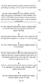
Fig. 5 , NRF = 4, t is a time variable, for example, two analog beamformers are obtain ad follows: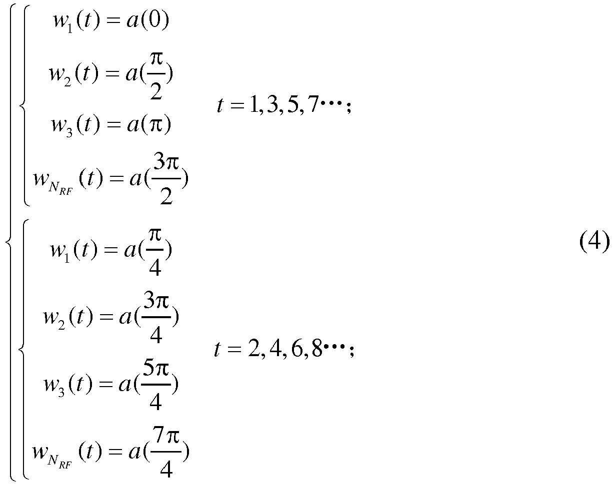
- In the above expression, the
values 1,3,5,7······ and 2,4,6,8······ only stand for a sequence in time domain, but not refer to the real number of timeslots. - In
block 505, the base station transmits the beamformed analog common signal in each RF chain. -
Fig. 7a is a schematic diagram illustrating a power spectrum of an antenna model using the first codeword group according to a second example of the present disclosure.Fig. 7b is a schematic diagram illustrating a power spectrum of an antenna model using the second codeword group according to a second example of the present disclosure. In the examples, 4 RF chains are configured and codewords in the codebook are divided into the first codeword group and the second codeword group. In one slot, as shownFig. 7a , common signals may cover the directions with steering angles of 0,

Fig. 7b , common signals may cover the directions with steering angles of


- In the example 2 as described above, all the RF chains (i.e., 4 RF chains) are used. In practical applications, part of RF chains may be used. And the number of codeword groups may be more than two. For example, when two RF chains are used, 8 codewords may be divided into 4 codeword groups.
- In addition, although digital beamforming is not described in the example 2 and shown in
Fig. 5 , it is equivalent to use a digital beamformer D(k) = [1 1 1 1] T to beamform the digital common signal before acquiring the analog common signal. -
Fig. 8 is a schematic diagram illustrating a structure of an apparatus for transmitting a common signal in hybrid beamforming according to a second example of the present disclosure. As shown inFig. 8 , the apparatus includes: a codewordgroup dividing module 801, an analog commonsignal acquiring module 802, an analogbeamformer obtaining module 803, ananalog beamforming module 804 and asignal transmitting module 805. - The codeword
group dividing module 801 is configured to divide codewords in the codebook for analog beamforming into at least two codeword groups, wherein each codeword group includes at least one codeword. - The analog common
signal acquiring module 802 is configured to acquire an analog common signal to be transmitted. - The analog
beamformer obtaining module 803 is configured to select a different codeword for each RF chain from a codebook for analog beamforming and obtain an analog beamformer. - The
analog beamforming module 804 is configured to beamform the analog common signal to be transmitted in each RF chain according to the analog beamformer. - The
signal transmitting module 805 is configured to transmit the beamformed analog common signal in each RF chain. In an example, thesignal transmitting module 404 may include an antenna sub-array corresponding to each RF chain. - Operations of modules as shown in
Fig. 8 are the same as the steps described in the method example 2 as shown inFig. 5 , which are not described in detail herein. - Based on any one of the above-described example 1 and example 2, in the example 3, the procedures of digital beamforming for the common signal are added.
-
Fig. 9a is a flow chart illustrating a method for transmitting a common signal in hybrid beamforming according to a third example of the present disclosure.Fig. 9b is a flow chart illustrating another method for transmitting a common signal in hybrid beamforming according to a third example of the present disclosure. As shown inFig. 9a andFig. 9b , the method includes the following procedures. - In
block 901, the base station acquires a digital common signal for generating an analog common signal to be transmitted. -
Fig. 10a is a schematic diagram illustrating a method for processing the common signal in hybrid beamforming according to a third example of the present disclosure.Fig. 10b is a schematic diagram illustrating another method for processing the common signal in hybrid beamforming according to a third example of the present disclosure. As shown inFig. 10a and Fig. 10b , the signal Sd is the digital common signal, and the Sa is the corresponding analog common signal to be transmitted. - In
block 902, the base station acquires a cyclic shift for each RF chain according to a principle of using different cyclic shifts for RF chains corresponding to adjacent beams, and generates a digital beamformer using the acquired cyclic shift, so that received signal power of common signals in the RF chains corresponding to adjacent beams are overlaid. Preferably, received signal power of common signals in the RF chains corresponding to adjacent beams is overlaid orthogonally or quasi-orthogonally. - In an example, cyclic shifts may be calculated according to the maximum multipath delay spread of the Channel Impulse Response (CIR) and the size of Discrete Fourier Transform (DFT). For example, the cyclic shift may be calculated as follows:

- In digital baseband, different RF chains corresponding to adjacent beams are beamformed with different cyclic shifts. For RF chains corresponding to non-adjacent beams, a same cyclic shift or different cyclic shifts may be used. For example, when the number of optional cyclic shifts is limited, RF chains corresponding to non-adjacent beams may be beamformed with a same cyclic shift. That is, at least it should be fulfilled that different cyclic shifts are used for the RF chains corresponding to adjacent beams, which may be applied to high frequency-selective channel scenario.
- In the above-described example 1 and example 2, as 4 RF chains are configured and the codebook for analog beamforming includes 8 codewords, assume two cyclic shifts are obtained, i.e., n 1 = 0,

RF chain 1 and RF chain 3 may use n 1, RF chain 2 and RF chain 4 may use n 2 . Accordingly, a digital beamformer may be generated as follows:
- By generating a digital beamformer in
block 902, it can be determined that the RF chains using different cyclic shifts may steer to adjacent beams. Thus, when performingblock 102 inFig. 9a and block 503 inFig. 9b , with respect to the RF chains using different cyclic shifts as described inblock 902, different codes which can steer to adjacent beams are selected. - In
block 903, the base station beamforms the digital common signal in each RF chain using the digital beamformer in digital baseband. - Further, the beamformed digital common signals may be performed with Inverse Fourier Transform (IFT) and DAC to obtain the analog common signal. Then, the base station performs the procedures of
Fig. 1 as shown inFig. 9a or performs the procedures ofFig. 5 as shown inFig. 9b , which are not described in detail herein. -
Fig. 11 is a schematic diagram illustrating a power spectrum of an antenna model according to a third example of the present disclosure. As shown inFig. 11 , common signals may cover the directions with steering angles of 0,

- As shown in
Fig. 11 , UE1, UE3, UE5 and UE7 are covered by separate beams, UE 2 are covered jointly bybeam 1 and beam 2, UE 4 are covered jointly by beam 2 and beam 3, UE 6 are covered jointly by beam 3 and beam 4, and UE 8 are covered jointly by beam 4 andbeam 1. -
Fig. 12 is a schematic diagram illustrating ECIR of UE1, UE 2 and UE3 according to an example of the present disclosure. For example, for UE 3, by digital beamforming with cyclic shifts and without cyclic shifts, the received signal power, its Probability Distribution Function (PDF), mean value and variance are compared as follows. - The received signal power with respect to digital beamforming without cyclic shifts is


- With respect to digital beamforming without cyclic shifts, the PDF is expressed as


- With respect to digital beamforming with cyclic shifts, the PDF is expressed as


-
Fig. 13a is a schematic diagram illustrating a structure of an apparatus for transmitting a common signal in hybrid beamforming according to a third example of the present disclosure.Fig. 13b is a schematic diagram illustrating a structure of another apparatus for transmitting a common signal in hybrid beamforming according to a third example of the present disclosure. As shown inFig. 13a andFig. 13b , besides the modules of the apparatuses described in example 1 and example 2, the apparatus further includes: a digital commonsignal acquiring module 1301, a digitalbeamformer obtaining module 1302 and adigital beamforming module 1303. - The digital common
signal acquiring module 1301 is configured to acquire a digital common signal for generating the analog common signal to be transmitted. - The digital
beamformer obtaining module 1302 is configured to acquire a cyclic shift for each RF chain according to a principle of using different cyclic shifts for RF chains corresponding to adjacent beams, and obtain a digital beamformer using the acquired cyclic shift;
Thedigital beamforming module 1303 is configured to beamform the digital common signal in each RF chain using the digital beamformer in digital baseband. - In an example, the cyclic shift may be calculated according to a maximum multipath delay spread of a CIR and a size of DFT. Accordingly, the apparatus further comprises a cyclic
shift calculating module 1304, configured to calculate the cyclic shift according to a maximum multipath delay spread of a CIR and a size of DFT, and send the cyclic shift to the digital beamformer generating module. - By simulation, methods described in the above three examples and a conventional scheme without beamforming is analyzed in terms of coverage area hereinafter. As shown in
Fig. 14 to Fig. 16 , the lightest oval at the far left corresponds to the a power spectrum of the antenna model in the conventional scheme, and the deeper oval at the right corresponds to the a power spectrum of the antenna model in the examples of the present disclosure. - Following are the simulation parameters in Table 1.
Item parameter Overall Tx power 46 dBm Number of RF chains 2 Size of antenna sub-array in each RF chain 10 antenna elements Analog beamforming codebook 
Antenna gain+ connection loss 17 dBi Antenna model (dB) 
φ3dB = 70°, Am = 25dB Pathloss (dB) PL(d) = 22log10(d) + 28 + 20log10 (fc ), wherein fc = 3.5GHz Threshold of the coverage -40 dBm -
Fig. 14 is a schematic diagram illustrating a power spectrum of an antenna model according to a first example of the present disclosure and a conventional scheme. The analog beamformer is A = diag[a(π/9) a(-π/9)]. - It can be seen that, the effective distance in the coverage area according to the example 1 is larger than that according to the conventional scheme, so that the pathloss of high frequency signals is well suppressed. The effective coverage area may change with the steering angle.
-
Fig. 15 is a schematic diagram illustrating a power spectrum of an antenna model according to a second example of the present disclosure and a conventional scheme. The analog beamformers are A I = diag [a(π/9) a(-π/9)] and A □ = diag[a(π/6) a(-π/6)]. - According to the example 2, dynamic beamforming is achieved by using these two beamformers in Time Division Multiplex (TDM). Compared with the conventional scheme, the coverage area is enlarged.
-
Fig. 16 is a schematic diagram illustrating a power spectrum of an antenna model according to a third example of the present disclosure and a conventional scheme. The analog beamformer is A = diag[α(π/9) a(-π/9)], the digital beamformer is D(k) = [1 e-jkπ ] T. - It can be seen that, according to the example 3, effective and robust coverage area is provided.
-
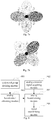
Fig. 17 is a schematic diagram illustrating a structure of a device for transmitting a common signal in hybrid beamforming according to an example of the present disclosure. As shown inFig. 17 , the device comprises aprocessor 1710 and amemory 1720 communicated with theprocessor 1710; in thememory 1720, the instructions that are executed by the processor are stored, comprising an analog commonsignal acquiring instruction 1721, an analogbeamformer obtaining instruction 1722, an analog beamforming instruction 1723, and asignal transmitting instruction 1724. - The analog common
signal acquiring instruction 1721 indicates to acquire an analog common signal to be transmitted. The analogbeamformer obtaining instruction 1722 indicates to select a different codeword for each RF chain from a codebook for analog beamforming and obtain an analog beamformer. The analog beamforming instruction 1723 indicates to beamform the analog common signal to be transmitted in each RF chain according to the analog beamformer. Thesignal transmitting instruction 1724 indicates to transmit the beamformed analog common signal in each RF chain. - In an example, the
memory 1720 may further store: a codeword group dividing instruction 1725, which indicates to divide codewords in the codebook for analog beamforming into at least two codeword groups, wherein each codeword group includes at least one codeword. - Accordingly, the analog
beamformer obtaining instruction 1722 indicates to select different codeword groups for adjacent timeslots, select a different codeword from the selected codeword group for each RF chain and obtain an analog beamformer. - In an example, the
memory 1720 may further store: a digital commonsignal acquiring instruction 1726, which indicates to acquire a digital common signal for generating the analog common signal to be transmitted; a digital beamformer obtaining instruction 1727, which indicates to acquire a cyclic shift for each RF chain according to a principle of using different cyclic shifts for RF chains corresponding to adjacent beams, and obtain a digital beamformer using the acquired cyclic shift; a digital beamforming instruction 1728, which indicates to beamform the digital common signal in each RF chain using the digital beamformer in digital baseband. - In an example, the
memory 1720 may further store: a cyclicshift calculating instruction 1729, which indicates to calculate the cyclic shift according to a maximum multipath delay spread of a channel impulse response and a size of discrete Fourier transform, and send the cyclic shift to the digital beamformer generating module.
Claims (6)
- A method for transmitting a common signal in hybrid beamforming, wherein the common signal is a signal transmitted in a common channel, and does not include user data, and the method comprises:acquiring a digital common signal for generating an analog common signal to be transmitted (901);acquiring a cyclic shift for each RF chain according to a principle of using different cyclic shifts for RF chains corresponding to adjacent beams and using a same cyclic shift for RF chains corresponding to non-adjacent beams, and generating a digital beamformer using the acquired cyclic shift (902);beamforming the digital common signal in each RF chain using the digital beamformer in digital baseband (903);acquiring the analog common signal to be transmitted (101, 502) by performing Inverse Fourier Transform and digital-to-analog conversion to the beamformed digital common signal;dividing codewords in a codebook for analog beamforming into at least two codeword groups (501) according to users' distribution;selecting different codeword groups for adjacent timeslots, selecting a different codeword from the selected codeword group for each RF chain according to a principle of achieving a uniform coverage in a cell based on beam directions corresponding to selected codewords, and obtaining an analog beamformer (102, 503);beamforming the analog common signal to be transmitted in each RF chain according to the analog beamformer (103, 504); andtransmitting the beamformed analog common signal in each RF chain (104, 505).
- The method of claim 1, wherein each codeword group includes at least one codeword.
- The method of claim 1, further comprising:
calculating the cyclic shift as follows:
- An apparatus for transmitting a common signal in hybrid beamforming, wherein the common signal is a signal transmitted in a common channel, and does not include user data, and the apparatus comprises:a digital common signal acquiring module (1301), configured to acquire a digital common signal for generating the analog common signal to be transmitted;a digital beamformer obtaining module (1302), configured to acquire a cyclic shift for each RF chain according to a principle of using different cyclic shifts for RF chains corresponding to adjacent beams and using a same cyclic shift for RF chains corresponding to non-adjacent beams, and obtain a digital beamformer using the acquired cyclic shift;a digital beamforming module (1303), configured to beamform the digital common signal in each RF chain using the digital beamformer in digital baseband;an analog common signal acquiring module (401, 802), configured to acquire an analog common signal to be transmitted by performing Inverse Fourier Transform and digital-to-analog conversion to the beamformed digital common signal;a codeword group dividing module (801), configured to divide codewords in the codebook for analog beamforming into at least two codeword groups according to users' distribution;an analog beamformer obtaining module (402, 803), configured to select different codeword groups for adjacent timeslots, select a different codeword from the selected codeword group for each RF chain according to a principle of achieving a uniform coverage in a cell based on beam directions corresponding to selected codewords, and obtain an analog beamformer;an analog beamforming module (403, 804), configured to beamform the analog common signal to be transmitted in each RF chain according to the analog beamformer; anda signal transmitting module (404, 805), configured to transmit the beamformed analog common signal in each RF chain.
- The apparatus of claim 4, wherein each codeword group includes at least one codeword.
- The apparatus of claim 4, further comprising:
a cyclic shift calculating module (1304), configured to calculate the cyclic shift as follows: wherein M is a maximum multipath delay spread of a channel impulse response, NFFT is a size of discrete Fourier transform, and, nk is the kth cyclic shift, k=0,1, ..., M-1,and send the cyclic shift to the digital beamformer obtaining module (1302).
Applications Claiming Priority (1)
| Application Number | Priority Date | Filing Date | Title |
|---|---|---|---|
| CN201410799868.2A CN105790806B (en) | 2014-12-19 | 2014-12-19 | Common signal transmission method and device in hybrid beam forming technology |
Publications (2)
| Publication Number | Publication Date |
|---|---|
| EP3035556A1 EP3035556A1 (en) | 2016-06-22 |
| EP3035556B1 true EP3035556B1 (en) | 2020-11-25 |
Family
ID=54366149
Family Applications (1)
| Application Number | Title | Priority Date | Filing Date |
|---|---|---|---|
| EP15193057.5A Active EP3035556B1 (en) | 2014-12-19 | 2015-11-04 | Method and apparatus for transmitting common signal in hybrid beamforming |
Country Status (4)
| Country | Link |
|---|---|
| US (1) | US9667334B2 (en) |
| EP (1) | EP3035556B1 (en) |
| JP (1) | JP6681692B2 (en) |
| CN (1) | CN105790806B (en) |
Families Citing this family (16)
| Publication number | Priority date | Publication date | Assignee | Title |
|---|---|---|---|---|
| EP3106594A1 (en) * | 2015-06-16 | 2016-12-21 | U-Shin Italia S.p.A. | Handle for a vehicle door |
| US10141993B2 (en) * | 2016-06-16 | 2018-11-27 | Intel Corporation | Modular antenna array beam forming |
| US9806777B1 (en) | 2016-06-24 | 2017-10-31 | Intel Corporation | Communication device and a method for beamforming |
| CN112615657A (en) * | 2016-07-25 | 2021-04-06 | 上海朗帛通信技术有限公司 | Method and device in wireless transmission |
| CN107733486B (en) * | 2016-08-12 | 2021-07-30 | 中兴通讯股份有限公司 | Information transmission method and device in hybrid beam forming system |
| EP3533149A1 (en) | 2016-10-27 | 2019-09-04 | Sony Corporation | Communication devices and methods with beamforming training |
| CN108365876A (en) * | 2017-01-26 | 2018-08-03 | 中国移动通信有限公司研究院 | A kind of digital beam-forming method for generating codebooks and equipment |
| TWI645689B (en) | 2017-12-15 | 2018-12-21 | 財團法人工業技術研究院 | Wireless communication device with hybrid beamforming and control method thereof |
| US10069519B1 (en) * | 2018-01-23 | 2018-09-04 | Mitsubishi Electric Research Laboratories, Inc. | Partition based distribution matcher for probabilistic constellation shaping |
| EP3804356A1 (en) | 2018-06-01 | 2021-04-14 | Shure Acquisition Holdings, Inc. | Pattern-forming microphone array |
| US10588089B1 (en) * | 2018-09-21 | 2020-03-10 | Qualcomm Incorporated | Mitigation of calibration errors |
| TW202044236A (en) | 2019-03-21 | 2020-12-01 | 美商舒爾獲得控股公司 | Auto focus, auto focus within regions, and auto placement of beamformed microphone lobes with inhibition functionality |
| WO2020237206A1 (en) | 2019-05-23 | 2020-11-26 | Shure Acquisition Holdings, Inc. | Steerable speaker array, system, and method for the same |
| JP2024505068A (en) | 2021-01-28 | 2024-02-02 | シュアー アクイジッション ホールディングス インコーポレイテッド | Hybrid audio beamforming system |
| CN116418380A (en) * | 2021-12-30 | 2023-07-11 | 华为技术有限公司 | Beam forming method, beam scanning method and related equipment |
| US11770163B1 (en) * | 2022-04-22 | 2023-09-26 | Qualcomm Incorporated | Interference mitigation for adaptive beam weight-based UL communications |
Family Cites Families (19)
| Publication number | Priority date | Publication date | Assignee | Title |
|---|---|---|---|---|
| US7826471B2 (en) * | 2003-03-11 | 2010-11-02 | Nortel Networks Limited | Multi-beam cellular communication system |
| KR100819285B1 (en) * | 2006-03-16 | 2008-04-02 | 삼성전자주식회사 | Method for transmiting/receiving feedback information in a multi-antenna system of selporting multi-user and system thereof |
| US8537790B2 (en) * | 2008-03-10 | 2013-09-17 | Motorola Mobility Llc | Hierarchical pilot structure in wireless communication systems |
| US8743985B2 (en) * | 2009-01-05 | 2014-06-03 | Intel Corporation | Method and apparatus using a base codebook structure for beamforming |
| KR101610305B1 (en) * | 2009-03-20 | 2016-04-20 | 삼성전자주식회사 | Apparatus and method for reducing inter-cell interference in multiple input multiple output system |
| KR20130017572A (en) * | 2011-08-11 | 2013-02-20 | 삼성전자주식회사 | Method and apparatus for determining analog beam in hybrid beamforming system |
| US9935699B2 (en) * | 2012-06-22 | 2018-04-03 | Samsung Electronics Co., Ltd. | Communication method and apparatus using beamforming in a wireless communication system |
| US9008222B2 (en) * | 2012-08-14 | 2015-04-14 | Samsung Electronics Co., Ltd. | Multi-user and single user MIMO for communication systems using hybrid beam forming |
| US9020061B2 (en) * | 2013-02-22 | 2015-04-28 | Nec Laboratories America, Inc. | Codebook construction |
| JP5738338B2 (en) * | 2013-03-29 | 2015-06-24 | 株式会社Nttドコモ | Radio communication system and radio base station apparatus |
| US9088312B2 (en) * | 2013-05-17 | 2015-07-21 | Samsung Electronics Co., Ltd. | Methods for linear RF beam search in millimeter wave communication system with hybrid beam-forming |
| US20150103934A1 (en) * | 2013-10-16 | 2015-04-16 | Electronics And Telecommunications Research Institute | Method and apparatus for communication in millimeter wave mimo communication environment |
| KR102039535B1 (en) * | 2013-10-22 | 2019-11-01 | 삼성전자 주식회사 | Method and apparatus for allocating radio resource |
| US10027395B2 (en) * | 2013-10-24 | 2018-07-17 | Lg Electronics Inc. | Method and device for reporting channel state information in wireless communication system |
| WO2015065156A1 (en) * | 2013-11-04 | 2015-05-07 | 엘지전자 주식회사 | Method and apparatus for transmitting signal in wireless communication system |
| KR102130285B1 (en) * | 2013-12-26 | 2020-07-08 | 삼성전자주식회사 | The method and apparatus for zero-forcing hybrid beamforming |
| KR102130294B1 (en) * | 2014-04-02 | 2020-07-08 | 삼성전자주식회사 | Method and apparatus for single stream multi-beam transmission and reception in wireless communication system |
| KR102258289B1 (en) * | 2014-05-22 | 2021-05-31 | 삼성전자 주식회사 | Method and apparatus for transmitting and generating channel feedback in 2 dimensional antena mobile communication system |
| US10476563B2 (en) * | 2014-11-06 | 2019-11-12 | Futurewei Technologies, Inc. | System and method for beam-formed channel state reference signals |
-
2014
- 2014-12-19 CN CN201410799868.2A patent/CN105790806B/en active Active
-
2015
- 2015-10-27 JP JP2015210384A patent/JP6681692B2/en active Active
- 2015-11-04 EP EP15193057.5A patent/EP3035556B1/en active Active
- 2015-12-18 US US14/974,003 patent/US9667334B2/en active Active
Non-Patent Citations (1)
| Title |
|---|
| None * |
Also Published As
| Publication number | Publication date |
|---|---|
| CN105790806B (en) | 2020-08-07 |
| US20160182138A1 (en) | 2016-06-23 |
| US9667334B2 (en) | 2017-05-30 |
| CN105790806A (en) | 2016-07-20 |
| JP2016119649A (en) | 2016-06-30 |
| EP3035556A1 (en) | 2016-06-22 |
| JP6681692B2 (en) | 2020-04-15 |
Similar Documents
| Publication | Publication Date | Title |
|---|---|---|
| EP3035556B1 (en) | Method and apparatus for transmitting common signal in hybrid beamforming | |
| US10355761B2 (en) | Beam administration methods for cellular/wireless networks | |
| US20240064043A1 (en) | Wireless communication method and wireless communication device | |
| US9537548B2 (en) | Random access channel using basis functions | |
| EP2243226B1 (en) | Beamforming in mimo systems | |
| US9160430B2 (en) | Millimeter-wave transceiver with coarse and fine beamforming with interference suppression and method | |
| US11791870B2 (en) | Radio communication system and radio base station apparatus | |
| Barati et al. | Directional cell search for millimeter wave cellular systems | |
| Stirling-Gallacher et al. | Multi-user MIMO strategies for a millimeter wave communication system using hybrid beam-forming | |
| CN106911371B (en) | Beam training method and device | |
| EP3499743B1 (en) | Transmission method and device for downlink receiving beam training signal | |
| EP3552457B1 (en) | System and method for fast system acquisition and channel estimation | |
| Khaled et al. | Joint SDMA and power-domain NOMA system for multi-user mm-wave communications | |
| US11005541B2 (en) | Method for transmitting feedback information and terminal therefor | |
| RU2589314C1 (en) | Method, system and device for signal transmission | |
| CN110622438B (en) | Method for transmitting feedback information in wireless communication system and apparatus therefor | |
| WO2017111961A1 (en) | Fast directional cell acquisition and differential beam tracking in millimeter-wave cellular system with hybrid beamforming architecture | |
| KR101679132B1 (en) | A method for multi-user signal transmission in massive antenna-based wireless communication systems | |
| Daba et al. | Performance analysis in 5th generation massive multiple-input-multiple-output systems | |
| Ullah et al. | Beam Detection Analysis for 5G mmWave Initial Acquisition | |
| CN110365391B (en) | Diversity receiving method for 5G downlink channel signal | |
| Liu et al. | Design and Implementation of a 5G NR Transmitter With Wi-Fi Coexistence by Beamforming and Power Control | |
| Kumar et al. | IMPLEMENTATION OF MASSIVE MIMO IN SUB-6 GHZ AND MMWAVE TECHNOLOGY USING HYBRID PRECODING | |
| Moon et al. | Fingerprint-Based Millimeter-Wave Beam Selection for Interference Mitigation in Beamspace Multi-User MIMO Communications | |
| WO2023191673A1 (en) | Method and network node for handling a phased array antenna module of a network node of a wireless communication network |
Legal Events
| Date | Code | Title | Description |
|---|---|---|---|
| PUAI | Public reference made under article 153(3) epc to a published international application that has entered the european phase |
Free format text: ORIGINAL CODE: 0009012 |
|
| AK | Designated contracting states |
Kind code of ref document: A1 Designated state(s): AL AT BE BG CH CY CZ DE DK EE ES FI FR GB GR HR HU IE IS IT LI LT LU LV MC MK MT NL NO PL PT RO RS SE SI SK SM TR |
|
| AX | Request for extension of the european patent |
Extension state: BA ME |
|
| STAA | Information on the status of an ep patent application or granted ep patent |
Free format text: STATUS: REQUEST FOR EXAMINATION WAS MADE |
|
| 17P | Request for examination filed |
Effective date: 20161026 |
|
| RBV | Designated contracting states (corrected) |
Designated state(s): AL AT BE BG CH CY CZ DE DK EE ES FI FR GB GR HR HU IE IS IT LI LT LU LV MC MK MT NL NO PL PT RO RS SE SI SK SM TR |
|
| STAA | Information on the status of an ep patent application or granted ep patent |
Free format text: STATUS: EXAMINATION IS IN PROGRESS |
|
| 17Q | First examination report despatched |
Effective date: 20190820 |
|
| REG | Reference to a national code |
Ref country code: DE Ref legal event code: R079 Ref document number: 602015062451 Country of ref document: DE Free format text: PREVIOUS MAIN CLASS: H04B0007040000 Ipc: H04B0007045600 |
|
| GRAP | Despatch of communication of intention to grant a patent |
Free format text: ORIGINAL CODE: EPIDOSNIGR1 |
|
| STAA | Information on the status of an ep patent application or granted ep patent |
Free format text: STATUS: GRANT OF PATENT IS INTENDED |
|
| RIC1 | Information provided on ipc code assigned before grant |
Ipc: H04B 7/06 20060101ALI20200429BHEP Ipc: H04B 7/0456 20170101AFI20200429BHEP |
|
| INTG | Intention to grant announced |
Effective date: 20200602 |
|
| GRAS | Grant fee paid |
Free format text: ORIGINAL CODE: EPIDOSNIGR3 |
|
| GRAA | (expected) grant |
Free format text: ORIGINAL CODE: 0009210 |
|
| STAA | Information on the status of an ep patent application or granted ep patent |
Free format text: STATUS: THE PATENT HAS BEEN GRANTED |
|
| AK | Designated contracting states |
Kind code of ref document: B1 Designated state(s): AL AT BE BG CH CY CZ DE DK EE ES FI FR GB GR HR HU IE IS IT LI LT LU LV MC MK MT NL NO PL PT RO RS SE SI SK SM TR |
|
| REG | Reference to a national code |
Ref country code: GB Ref legal event code: FG4D |
|
| REG | Reference to a national code |
Ref country code: CH Ref legal event code: EP |
|
| REG | Reference to a national code |
Ref country code: AT Ref legal event code: REF Ref document number: 1339477 Country of ref document: AT Kind code of ref document: T Effective date: 20201215 |
|
| REG | Reference to a national code |
Ref country code: DE Ref legal event code: R096 Ref document number: 602015062451 Country of ref document: DE |
|
| REG | Reference to a national code |
Ref country code: IE Ref legal event code: FG4D |
|
| REG | Reference to a national code |
Ref country code: AT Ref legal event code: MK05 Ref document number: 1339477 Country of ref document: AT Kind code of ref document: T Effective date: 20201125 |
|
| REG | Reference to a national code |
Ref country code: NL Ref legal event code: MP Effective date: 20201125 |
|
| PG25 | Lapsed in a contracting state [announced via postgrant information from national office to epo] |
Ref country code: RS Free format text: LAPSE BECAUSE OF FAILURE TO SUBMIT A TRANSLATION OF THE DESCRIPTION OR TO PAY THE FEE WITHIN THE PRESCRIBED TIME-LIMIT Effective date: 20201125 Ref country code: FI Free format text: LAPSE BECAUSE OF FAILURE TO SUBMIT A TRANSLATION OF THE DESCRIPTION OR TO PAY THE FEE WITHIN THE PRESCRIBED TIME-LIMIT Effective date: 20201125 Ref country code: NO Free format text: LAPSE BECAUSE OF FAILURE TO SUBMIT A TRANSLATION OF THE DESCRIPTION OR TO PAY THE FEE WITHIN THE PRESCRIBED TIME-LIMIT Effective date: 20210225 Ref country code: PT Free format text: LAPSE BECAUSE OF FAILURE TO SUBMIT A TRANSLATION OF THE DESCRIPTION OR TO PAY THE FEE WITHIN THE PRESCRIBED TIME-LIMIT Effective date: 20210325 Ref country code: GR Free format text: LAPSE BECAUSE OF FAILURE TO SUBMIT A TRANSLATION OF THE DESCRIPTION OR TO PAY THE FEE WITHIN THE PRESCRIBED TIME-LIMIT Effective date: 20210226 |
|
| PG25 | Lapsed in a contracting state [announced via postgrant information from national office to epo] |
Ref country code: IS Free format text: LAPSE BECAUSE OF FAILURE TO SUBMIT A TRANSLATION OF THE DESCRIPTION OR TO PAY THE FEE WITHIN THE PRESCRIBED TIME-LIMIT Effective date: 20210325 Ref country code: SE Free format text: LAPSE BECAUSE OF FAILURE TO SUBMIT A TRANSLATION OF THE DESCRIPTION OR TO PAY THE FEE WITHIN THE PRESCRIBED TIME-LIMIT Effective date: 20201125 Ref country code: PL Free format text: LAPSE BECAUSE OF FAILURE TO SUBMIT A TRANSLATION OF THE DESCRIPTION OR TO PAY THE FEE WITHIN THE PRESCRIBED TIME-LIMIT Effective date: 20201125 Ref country code: LV Free format text: LAPSE BECAUSE OF FAILURE TO SUBMIT A TRANSLATION OF THE DESCRIPTION OR TO PAY THE FEE WITHIN THE PRESCRIBED TIME-LIMIT Effective date: 20201125 Ref country code: BG Free format text: LAPSE BECAUSE OF FAILURE TO SUBMIT A TRANSLATION OF THE DESCRIPTION OR TO PAY THE FEE WITHIN THE PRESCRIBED TIME-LIMIT Effective date: 20210225 Ref country code: AT Free format text: LAPSE BECAUSE OF FAILURE TO SUBMIT A TRANSLATION OF THE DESCRIPTION OR TO PAY THE FEE WITHIN THE PRESCRIBED TIME-LIMIT Effective date: 20201125 |
|
| REG | Reference to a national code |
Ref country code: LT Ref legal event code: MG9D |
|
| PG25 | Lapsed in a contracting state [announced via postgrant information from national office to epo] |
Ref country code: HR Free format text: LAPSE BECAUSE OF FAILURE TO SUBMIT A TRANSLATION OF THE DESCRIPTION OR TO PAY THE FEE WITHIN THE PRESCRIBED TIME-LIMIT Effective date: 20201125 |
|
| PG25 | Lapsed in a contracting state [announced via postgrant information from national office to epo] |
Ref country code: RO Free format text: LAPSE BECAUSE OF FAILURE TO SUBMIT A TRANSLATION OF THE DESCRIPTION OR TO PAY THE FEE WITHIN THE PRESCRIBED TIME-LIMIT Effective date: 20201125 Ref country code: SK Free format text: LAPSE BECAUSE OF FAILURE TO SUBMIT A TRANSLATION OF THE DESCRIPTION OR TO PAY THE FEE WITHIN THE PRESCRIBED TIME-LIMIT Effective date: 20201125 Ref country code: LT Free format text: LAPSE BECAUSE OF FAILURE TO SUBMIT A TRANSLATION OF THE DESCRIPTION OR TO PAY THE FEE WITHIN THE PRESCRIBED TIME-LIMIT Effective date: 20201125 Ref country code: SM Free format text: LAPSE BECAUSE OF FAILURE TO SUBMIT A TRANSLATION OF THE DESCRIPTION OR TO PAY THE FEE WITHIN THE PRESCRIBED TIME-LIMIT Effective date: 20201125 Ref country code: CZ Free format text: LAPSE BECAUSE OF FAILURE TO SUBMIT A TRANSLATION OF THE DESCRIPTION OR TO PAY THE FEE WITHIN THE PRESCRIBED TIME-LIMIT Effective date: 20201125 Ref country code: EE Free format text: LAPSE BECAUSE OF FAILURE TO SUBMIT A TRANSLATION OF THE DESCRIPTION OR TO PAY THE FEE WITHIN THE PRESCRIBED TIME-LIMIT Effective date: 20201125 |
|
| REG | Reference to a national code |
Ref country code: DE Ref legal event code: R097 Ref document number: 602015062451 Country of ref document: DE |
|
| PG25 | Lapsed in a contracting state [announced via postgrant information from national office to epo] |
Ref country code: DK Free format text: LAPSE BECAUSE OF FAILURE TO SUBMIT A TRANSLATION OF THE DESCRIPTION OR TO PAY THE FEE WITHIN THE PRESCRIBED TIME-LIMIT Effective date: 20201125 |
|
| PLBE | No opposition filed within time limit |
Free format text: ORIGINAL CODE: 0009261 |
|
| STAA | Information on the status of an ep patent application or granted ep patent |
Free format text: STATUS: NO OPPOSITION FILED WITHIN TIME LIMIT |
|
| PG25 | Lapsed in a contracting state [announced via postgrant information from national office to epo] |
Ref country code: NL Free format text: LAPSE BECAUSE OF FAILURE TO SUBMIT A TRANSLATION OF THE DESCRIPTION OR TO PAY THE FEE WITHIN THE PRESCRIBED TIME-LIMIT Effective date: 20201125 Ref country code: AL Free format text: LAPSE BECAUSE OF FAILURE TO SUBMIT A TRANSLATION OF THE DESCRIPTION OR TO PAY THE FEE WITHIN THE PRESCRIBED TIME-LIMIT Effective date: 20201125 Ref country code: IT Free format text: LAPSE BECAUSE OF FAILURE TO SUBMIT A TRANSLATION OF THE DESCRIPTION OR TO PAY THE FEE WITHIN THE PRESCRIBED TIME-LIMIT Effective date: 20201125 |
|
| 26N | No opposition filed |
Effective date: 20210826 |
|
| PG25 | Lapsed in a contracting state [announced via postgrant information from national office to epo] |
Ref country code: ES Free format text: LAPSE BECAUSE OF FAILURE TO SUBMIT A TRANSLATION OF THE DESCRIPTION OR TO PAY THE FEE WITHIN THE PRESCRIBED TIME-LIMIT Effective date: 20201125 Ref country code: SI Free format text: LAPSE BECAUSE OF FAILURE TO SUBMIT A TRANSLATION OF THE DESCRIPTION OR TO PAY THE FEE WITHIN THE PRESCRIBED TIME-LIMIT Effective date: 20201125 |
|
| PG25 | Lapsed in a contracting state [announced via postgrant information from national office to epo] |
Ref country code: IS Free format text: LAPSE BECAUSE OF FAILURE TO SUBMIT A TRANSLATION OF THE DESCRIPTION OR TO PAY THE FEE WITHIN THE PRESCRIBED TIME-LIMIT Effective date: 20210325 |
|
| PG25 | Lapsed in a contracting state [announced via postgrant information from national office to epo] |
Ref country code: MC Free format text: LAPSE BECAUSE OF FAILURE TO SUBMIT A TRANSLATION OF THE DESCRIPTION OR TO PAY THE FEE WITHIN THE PRESCRIBED TIME-LIMIT Effective date: 20201125 |
|
| REG | Reference to a national code |
Ref country code: CH Ref legal event code: PL |
|
| PG25 | Lapsed in a contracting state [announced via postgrant information from national office to epo] |
Ref country code: LU Free format text: LAPSE BECAUSE OF NON-PAYMENT OF DUE FEES Effective date: 20211104 Ref country code: BE Free format text: LAPSE BECAUSE OF NON-PAYMENT OF DUE FEES Effective date: 20211130 |
|
| REG | Reference to a national code |
Ref country code: BE Ref legal event code: MM Effective date: 20211130 |
|
| PG25 | Lapsed in a contracting state [announced via postgrant information from national office to epo] |
Ref country code: IE Free format text: LAPSE BECAUSE OF NON-PAYMENT OF DUE FEES Effective date: 20211104 |
|
| PG25 | Lapsed in a contracting state [announced via postgrant information from national office to epo] |
Ref country code: FR Free format text: LAPSE BECAUSE OF NON-PAYMENT OF DUE FEES Effective date: 20211130 |
|
| PG25 | Lapsed in a contracting state [announced via postgrant information from national office to epo] |
Ref country code: HU Free format text: LAPSE BECAUSE OF FAILURE TO SUBMIT A TRANSLATION OF THE DESCRIPTION OR TO PAY THE FEE WITHIN THE PRESCRIBED TIME-LIMIT; INVALID AB INITIO Effective date: 20151104 |
|
| P01 | Opt-out of the competence of the unified patent court (upc) registered |
Effective date: 20230509 |
|
| PG25 | Lapsed in a contracting state [announced via postgrant information from national office to epo] |
Ref country code: CY Free format text: LAPSE BECAUSE OF FAILURE TO SUBMIT A TRANSLATION OF THE DESCRIPTION OR TO PAY THE FEE WITHIN THE PRESCRIBED TIME-LIMIT Effective date: 20201125 |
|
| PG25 | Lapsed in a contracting state [announced via postgrant information from national office to epo] |
Ref country code: LI Free format text: LAPSE BECAUSE OF NON-PAYMENT OF DUE FEES Effective date: 20220630 Ref country code: CH Free format text: LAPSE BECAUSE OF NON-PAYMENT OF DUE FEES Effective date: 20220630 |
|
| PGFP | Annual fee paid to national office [announced via postgrant information from national office to epo] |
Ref country code: GB Payment date: 20231123 Year of fee payment: 9 |
|
| PGFP | Annual fee paid to national office [announced via postgrant information from national office to epo] |
Ref country code: DE Payment date: 20231121 Year of fee payment: 9 |
|
| PG25 | Lapsed in a contracting state [announced via postgrant information from national office to epo] |
Ref country code: MK Free format text: LAPSE BECAUSE OF FAILURE TO SUBMIT A TRANSLATION OF THE DESCRIPTION OR TO PAY THE FEE WITHIN THE PRESCRIBED TIME-LIMIT Effective date: 20201125 |