EP3034720B1 - A lock device for a double door and uses thereof - Google Patents
A lock device for a double door and uses thereof Download PDFInfo
- Publication number
- EP3034720B1 EP3034720B1 EP14199241.2A EP14199241A EP3034720B1 EP 3034720 B1 EP3034720 B1 EP 3034720B1 EP 14199241 A EP14199241 A EP 14199241A EP 3034720 B1 EP3034720 B1 EP 3034720B1
- Authority
- EP
- European Patent Office
- Prior art keywords
- lock
- door
- locking
- exterior
- lock device
- Prior art date
- Legal status (The legal status is an assumption and is not a legal conclusion. Google has not performed a legal analysis and makes no representation as to the accuracy of the status listed.)
- Active
Links
- 230000007246 mechanism Effects 0.000 claims description 7
- 239000007787 solid Substances 0.000 claims description 6
- 238000005553 drilling Methods 0.000 claims description 5
- 229910052751 metal Inorganic materials 0.000 claims description 5
- 239000002184 metal Substances 0.000 claims description 5
- 238000000034 method Methods 0.000 claims description 5
- 229910001385 heavy metal Inorganic materials 0.000 claims description 2
- 229910000831 Steel Inorganic materials 0.000 description 8
- 239000010959 steel Substances 0.000 description 8
- 238000003466 welding Methods 0.000 description 5
- 230000004308 accommodation Effects 0.000 description 4
- 230000007704 transition Effects 0.000 description 2
- 230000008901 benefit Effects 0.000 description 1
- 230000000295 complement effect Effects 0.000 description 1
- 238000003780 insertion Methods 0.000 description 1
- 230000037431 insertion Effects 0.000 description 1
- 230000008569 process Effects 0.000 description 1
- 238000000926 separation method Methods 0.000 description 1
- 230000000007 visual effect Effects 0.000 description 1
- XLYOFNOQVPJJNP-UHFFFAOYSA-N water Substances O XLYOFNOQVPJJNP-UHFFFAOYSA-N 0.000 description 1
Images


Classifications
-
- E—FIXED CONSTRUCTIONS
- E05—LOCKS; KEYS; WINDOW OR DOOR FITTINGS; SAFES
- E05B—LOCKS; ACCESSORIES THEREFOR; HANDCUFFS
- E05B17/00—Accessories in connection with locks
- E05B17/20—Means independent of the locking mechanism for preventing unauthorised opening, e.g. for securing the bolt in the fastening position
- E05B17/2084—Means to prevent forced opening by attack, tampering or jimmying
- E05B17/2088—Means to prevent disengagement of lock and keeper
-
- E—FIXED CONSTRUCTIONS
- E05—LOCKS; KEYS; WINDOW OR DOOR FITTINGS; SAFES
- E05B—LOCKS; ACCESSORIES THEREFOR; HANDCUFFS
- E05B63/00—Locks or fastenings with special structural characteristics
- E05B63/0004—Additional locks added to existing lock arrangements
-
- E—FIXED CONSTRUCTIONS
- E05—LOCKS; KEYS; WINDOW OR DOOR FITTINGS; SAFES
- E05B—LOCKS; ACCESSORIES THEREFOR; HANDCUFFS
- E05B83/00—Vehicle locks specially adapted for particular types of wing or vehicle
- E05B83/02—Locks for railway freight-cars, freight containers or the like; Locks for the cargo compartments of commercial lorries, trucks or vans
-
- E—FIXED CONSTRUCTIONS
- E05—LOCKS; KEYS; WINDOW OR DOOR FITTINGS; SAFES
- E05B—LOCKS; ACCESSORIES THEREFOR; HANDCUFFS
- E05B9/00—Lock casings or latch-mechanism casings ; Fastening locks or fasteners or parts thereof to the wing
- E05B9/08—Fastening locks or fasteners or parts thereof, e.g. the casings of latch-bolt locks or cylinder locks to the wing
-
- E—FIXED CONSTRUCTIONS
- E05—LOCKS; KEYS; WINDOW OR DOOR FITTINGS; SAFES
- E05C—BOLTS OR FASTENING DEVICES FOR WINGS, SPECIALLY FOR DOORS OR WINDOWS
- E05C7/00—Fastening devices specially adapted for two wings
- E05C7/04—Fastening devices specially adapted for two wings for wings which abut when closed
Definitions
- the present invention relates to a lock device for a double door, the lock device comprising a
- the present invention relates to an anti-theft lock device for securing e.g. cargo, shipping or storage containers having double doors, however the lock device according to the present invention can be used on any device, compartment, room or unit to secure possessions and content.
- lock device The weakest part of such a container, especially when being used for storage, is the lock device. Most such lock devices do not come as an integral part of the container. Often the lock devices are mounted later by the end user and can have any level of strength. There are several types of lock devices. Cheaper lock devices tend to be weaker, while expensive lock devices can, but need not, be more secure. Some may even be completely ineffective in deterring thefts. For some conventional lock devices it will even be impossible to detect evidence of tampering until it is discovered that content is missing.
- An exemplary conventional lock device is a lock device box comprising a steel house that protects a padlock from being cut or broken in any way. By enclosing the padlock it makes the container much harder to break into and less attractive to thieves.
- One exemplary lock device box is a so-called "weld-on lock box" which the end user welds on the container doors.
- the weld-on lock box confines a padlock inside a weld-on house. Someone trying to break into the container would normally just cut the lock shank of the padlock, which padlock however is difficult accessible due to being hidden inside the small enclosed area of the weld-on house.
- a disadvantage of weld-on lock boxes is the requirement for welding equipment.
- a lock device designed specifically to clamp on the container's vertical locking bars and using a pin lock with a key.
- the conventional "clamp-on lock device” can be moved from container to container.
- a lock device to be positioned on the outside of the double doors of a truck. Screws through the doors and nuts on the inside of the doors attach the lock device to the doors.
- a lock device of the type mentioned in the opening paragraph that is easy to operate and position as protectively as possible.
- a lock device of the type mentioned in the opening paragraph that effectively deters break-ins and secures cargo and content.
- a lock device of the type mentioned in the opening paragraph that is difficult to cut with hand-operated tools.
- a lock device of the type mentioned in the opening paragraph that can be mounted fast and efficiently on existing and new containers, optionally be moved from one container to another.
- a lock device of the type mentioned in the opening paragraph that can be mounted without welding equipment.
- the term "container” refers to large containers for storage, cargo, shipping, freight etc., e.g. high cube steel containers.
- the double door can, but need not, be provided in or constitute the short end wall of the container, but other positions of the double door is not excluded. Means for tamper-proofing may also be provided.
- a conventional "bolt-on lock device box” also utilizes bolt means.
- the length of the bolt is selected so that it can pass through the container door to be fastened by a nut directly on the interior side of the container door, thus without interposed interior part as in the present invention. So the "bolt-on lock device box” differs from the present invention in not having an interior part of a lock part other than the nut, just an exterior part of a lock part to be mounted exterior to the container.
- the bolt means ensures that each lock part remains in fixed position on its associated door during opening and closing of the double door. Emphasize is thus made that for the present invention a suitable long bolt means is needed to reach through both the container door wall and the interior part.
- a further difference is that the female interlocking and/or engagement means engaging the male interlocking and/or engagement means of the respective interior parts result in that interlocking and/or engagement of the first door's first lock part and the second door's second lock part takes place inside the container, not outside the container as for conventional lock devices. Final anti-theft locking after closing the double door is done by actuating and locking the lock of the lock device.
- At least a part of the lock itself may be positioned on an interior part and being operable from outside the double door, e.g. from an exterior part outside a double door for a container.
- the initial interlocking and/or engagement operation of the double door takes place upon closing the double door. In doing so the first door with the female interlocking and/or engagement means is closed. Then the second door is closed so that the male interlocking and/or engagement means of the second interior part is inserted to engage and/or lock into the female interlocking and/or engagement means of the first interior part. Once the double door is closed the lock can be operated from outside the double door to finally securely lock said double door.
- the first locking profile and the second locking profile overlap to interlock and/or engage in the closed position of the double door. At least one of the first and second locking profiles may thus extend beyond the front edge of the opposite door on the backside of the double door when it is closed.
- the first locking profile that defines the female locking component may e.g. protrude laterally from the first plate towards the second locking profile over the backside of the second door.
- the locking of the double door becomes an extra anti-theft means in addition to the lock, because neither the interior part of the lock nor the first locking profile and the second locking profile are accessible to thieves.
- the male protrusion of the second locking profile which is positioned inside the locking cavity of the first locking profile, severely obstructs pivotability of the opposite individual doors, thereby making unauthorised opening even more difficult.
- the first plate and the second plate also expediently serve as washer plates for the respective first bolt means and second bolt means.
- the locking groove or cavity is closed at least at one of opposite ends by an end plate.
- the locking groove or cavity of the first locking profile is closed at opposite ends by an upper end plate and a lower end plate, respectively.
- the end plates provide guidance for inserting the second locking profile inside the groove or cavity of the first locking profile.
- the lower end plate advantageously further serves for keeping the first and second lock openings aligned. For example double doors of metal storage containers are very heavy and may dislocate vertically. Only a small vertical dislocation can cause dislocation of the alignment of the locking openings. When the second door is closed the lower end of the second locking profile plate can rest on the lower plate thereby keeping the alignment of the opposite locking opening required for the proper function of the lock device.
- the first locking profile may e.g. be a U-profile and the second locking profile may be a web fitting between the legs of the U-profile of the first locking profile.
- the legs of the U-profile fit as tightly as possible, e.g. with a clearance on opposite sides of the web of less than 0.5 cm, alternatively less than 0.3 cm, alternatively less than 0.2 cm.
- the first lock part may comprise the lock, which lock is adapted for displacing a lock bolt through aligned first and second lock openings.
- These aligned first and second lock openings may be a first lock opening of the female first locking profile and/or engagement means and a second lock opening of the male second locking profile and/or engagement means.
- the lock bolt through these aligned openings are thus hidden from outside the closed double door by being provided on the backside of the double door.
- the lock bolt inside the container, and thus the lock is operated from outside the container to block separation and movement of the opposite interlocked and/or engaged interior parts when the lock bolt passes through both lock openings.
- first lock opening is provided in the first locking profile and the second lock opening is provided in the second locking profile so that when these locking profiles interlock and/or engage the lock bolt traverse both locking profiles inside the closed container and is complete inaccessible to be cut by any tool or otherwise manipulated.
- first exterior part and the second exterior part is/are solid metal block(s), preferably heavy metal block(s), such as steel blocks which are in intimate contact with the respective container door once mounted.
- heavy blocks required massive tool capacity, effort and time to demount unauthorised, e.g. to cut off or just deteriorate, and even if the thieve is lucky to cut off any of the first exterior part and the second exterior part the interlocking of the interior parts are still a hindrance for the thieve to open the double door.
- the first interior part and the second interior part may be made of metal as well.
- a further advantage of this embodiment is that the block design can provide good and safe accommodation of more or less embedded parts of the lock.
- the lock has a lock cylinder the keyway can beneficially be embedded in the first exterior part of the first lock part, simply by drilling an accommodation hole and place the keyway in the accommodation hole with a spindle protruding through the respective door to operate a locking mechanism provided on or in relation to the surface of the first plate that faces away from the first door, thus when e.g. the double door is mounted on a container the locking mechanism is mounted on the face of the first plate facing inside the container.
- the only part of the keyway exposed to the environment when the double door is closed is the keyhole 13a, and preferably the cylinder and thus the keyway is mounted retracted inside the block of the first exterior part so that even the keyhole 13a is displaced axially inside the accommodation hole.
- the rather large mass of metal surrounding the cylinder and keyway then also protects the cylinder and keyway from unintended tampering and physical access.
- the spindle can advantageous be adapted to have adjustable length, so that one lock device can be fitted on different doors having various thickness.
- the lock is electronic, in which embodiment no parts or components at all of the electronic lock are provided on any of the exterior parts.
- the lock is exclusively provided behind the double door and no keyhole and cylinder needed in the first exterior part.
- Such an electronic lock can lock and un-lock the double door from both inside and outside the double door.
- a suitable means for mounting and keeping the lock device correctly on the double door may be configured so that the first bolt means includes a first bolt and a first nut, and the second bolt means includes a second bolt and a second nut.
- the first bolt and/or the second bolt are threaded and/or the first nut and/or the second nut is/are a screw nut.
- first exterior part and the second exterior part of the lock device may have exterior curved faces, e.g. to make a smooth transition towards the exterior surface of the respective door when the lock device is mounted on the double door, thereby making the visual design more elegant.
- the second door may be the active door and the first door be the passive door. Which door is the passive or the active depends on which door the first locking profile and the second locking profile are provided on, in that the female locking profile needs to be on the passive part to cooperate with the male locking profile upon closing the double door.
- the first door may be configured as the second door, and the second door be configured as the first door.
- the present invention also relate to a method of mounting the lock device described above on a double door, e.g. the double door of a container.
- the method comprises the steps of
- the spindle of the lock device extends from the first exterior part through the first door to operate the lock mechanism on the first interior part to displace the lock bolt through the aligned first and second openings of the respective first and second locking profiles.
- the lock device according to the present invention can be used to lock up other kinds of enclosures and compartments than containers as defined above.
- the lock device can be used for locking together opposite doors of any closure arrangement for a compartment, including double doors for gateways, entrance points, fencings, etc. This list is not exhaustive and other uses are foreseen within the scope of the present invention.
- the first lock part is mounted on the left door of a storage container when viewed from outside the container
- the second lock part is mounted on the right door of the storage container when viewed from outside the container.
- the left door is the first door
- the right door is the second door.
- this arrangement shall not be seen as limiting the versatility of mounting the lock parts. So in an alternative embodiment the first lock part can be mounted on the left door and the second lock part be mounted on the right door of the storage container when viewed from outside the container.
- the lock device is only by way of example shown on a storage container. Emphasise is made that the lock device can be used on other objects having double doors.
- Fig. 1 is a perspective exploded view of the first lock part 1 of a lock device 1,2 seen from the first exterior part 3 opposite the first interior part 4, and fig. 2 shows the first lock part 1 from the first exterior part 4.
- the closed lock device 1,2 is shown and described in subsequent drawings.
- the first exterior part 3 is a solid steel block wherein a first bolt means 5 is secured to protrude towards the first interior lock part 4 through appropriate holes drilled, or otherwise provided, in a first door (not shown).
- the first interior lock part 4 includes a first plate 6, which has a female first locking profile 7, in form of a U-profile, in extension of a first edge 8 of the first plate 6.
- the double door is a container double door having vertically hinged doors the first edge 8 is typically vertical when the lock device 1,2 is mounted to the double door and the container is placed on the ground, and so is the female first locking profile 7.
- a first contact face 9 of the first plate 6 is mounted onto the first door, and an opposite lock support face 10 serves for supporting and mounting a lock box 11 of the lock.
- the lock box 11 has a lock bolt 12, in the present case a square bolt, to be operated by means of a key for a cylinder 13 of a cylinder lock, e.g. similarly to a conventional cylinder lock, which is mounted in the first exterior lock part 3, as will be described further below.
- a lock bolt 12 in the present case a square bolt, to be operated by means of a key for a cylinder 13 of a cylinder lock, e.g. similarly to a conventional cylinder lock, which is mounted in the first exterior lock part 3, as will be described further below.
- first exterior lock part 3 When the first exterior lock part 3 is mounted on the first door of the double door the long bolts 5a,5b,5c of the first bolt means 5 of the first exterior lock part 3 pass through drilled holes in the first door and further through three aligned first holes 14a,14b,14c in the first plate 6 of the first interior lock part 4. Then the first exterior lock part 3 is firmly secured to said first plate 6 by means of three associated sets of first washers 15a,15b,15c and first nuts 16a,16b,16c, which are tightened to the lock support face 10 of the first plate 6, thereby sandwiching the wall of the double door in-between the first exterior lock part 3 and the first interior lock part 4.
- the position on the first plate 6 of the assembled first bolt means 5 and the co-operating first washers 15a,15b,15c and first nuts 16a,16b,16c does not overlap the lock box 11 and has no impact on the operation and function of the lock.
- This assembled fastening means 5;15a,15b,15c; 16a,16b,16c ensures solid and reliable mounting of the first lock part 1 on the first door.
- This position of assembled first bolt means 5, first washers 15a,15b,15c and first nuts 16a,16b,16c is shown and given in the figures just by way of example for the present embodiment, and can be any position that is not in the way for the operation of any other means of the lock device 1,2.
- the U-profiled female first locking profile 7 is defined by a first leg 17a that extends from the first edge 8 of the first plate 6 into a second leg 17b via the bottom wall of the U-profile 7 to define a groove, cavity or gap 18 for receiving a male part of a second lock part, as will be explained in further details below with references to the further figures.
- a recess 19 of the first leg 17a serves to accommodate a front part 20 of the lock box 12, which front part 20 is inserted laterally in the first leg 17a, so that the lock bolt 12 can reciprocate inside a first lock opening 20 traversing the first leg 17a via the recess 19.
- the lock box 11 can be mounted to the lock support face 10 of the first plate 6 using any appropriate method, including welding to the first plate 6 and/or screwing or force-fitting.
- first through-holes 20a',20b' disposed vertically on opposite sides of the first lock opening 20 serve for receiving first lock box screws 20a", 20b" to firmly further fasten the lock box 11 laterally in the recess 19 of said first lock profile 7.
- Axially the lock box 11 is fastened to the plate 6 by means of second lock box screws 39a', 39b' in second through-holes 39a", 39b" made in the first plate 6 and further to the lock box by means of third through-holes 40a', 40b'.
- the cylinder 13 of the cylinder lock is mounted in a cylinder lock hole 21 in the first exterior lock part 3 so as to be encased, embedded and hidden for thieves and intruders. Only a keyhole 13a is visible and accessible from outside the first exterior lock part 3.
- the cylinder lock hole 21 has a reduced diameter at the exterior face of the first exterior part 3 to only provide for access to a keyhole 13a, which keyhole 13a preferably is retracted from said exterior face of the first exterior part 3.
- the cylinder lock includes a holder 22 for holding an enlarged head 23 of a first elongated and extended spindle part 24 in operatively engagement with the cylinder 13.
- the enlarged head 23 has a head recess 25 for engaging a male extension 26 on the cylinder 13, so that when the key is turned, so is the first elongated and extended spindle part 24.
- the enlarged head 23 of this first spindle part 24 has an extension in form of an elongated split neck part 27.
- This split neck part 27 has an axial slit 28, which in the embodiment shown extends from the enlarged head 23 to the free end 29 of the split neck part 27, to allow for inserting a male second spindle part 30 provided on the lock box 11 so that the length of the combined spindle can be adjusted to the thickness of different first doors.
- the second spindle part 30 is operatively connected to the lock bolt 12, so that when the male second spindle part 30 is engaged inside the axially extending second split neck part 27, the lock bolt 12 can be displaced laterally to pass in and out of at the aligned first lock opening 20 and second lock opening upon turning a key.
- the spindle 24,30 are much longer than for a conventional key lock or pin lock, the lock bolt 12 can be operatively connected via a conventional locking mechanism.
- the engaging first spindle part 24 and second spindle part 30 are mounted inside a pipe guide piece 31 to prevent disengagement when the combined engaged spindle structure 24,30 rotates to thereby displace the lock bolt 12 laterally through the first lock opening 20 and second lock opening to lock the double door.
- the guide pipe piece 31 reaches through a guide hole 32 in the first plate 6 so that one end 31a of the guide pipe piece 31 abuts the enlarged head 23 of the first spindle part 24 and the opposite end 31b of the guide pipe piece 31 reaches towards, optionally into, the lock box 11.
- the pipe guide piece 31 further holds on to the engaging spindle parts 24,30 even though said spindle parts 24,30 are not engaged along the entire length, e.g. in case of a thick first door that only allows some of the opposite co-operating lengths of the spindle parts 24,30 to overlap to engage.
- the guide pipe piece helps to control engagement of the spindle parts 24,30.
- the engaging male extension 26 of the cylinder 13 located in the head recess 25 and the enlarged head 23 of the first spindle part 24 are rotatably arranged in a complementary cavity 22a of the holder 22 to further prevent disengagement of male extension 26 and head recess 25.
- the assembled cylinder 13, holder 22, and enlarged head 23 of the first spindle part 24 are mounted inside cylinder lock hole 21 of the first exterior part and held in place inside said cylinder lock hole 21 by means of a first cover plate 33, which has a first cover plate hole 34 for exiting the split neck part 27 of the first spindle part 24.
- First screws 35 serve to screw the first cover plate 33, the holder 22, and the cylinder 13 together using holes provided fro that purpose in the respective componet.
- the diameter of the first cover plate hole 34 is smaller than the diameter of the enlarged head 23, so that when the assembly of first cover plate 33, holder 22, and cylinder 13 is secured to the first exterior lock part 3 by means of second screws 36, this difference in diameter serves as an additional means to make sure that the enlarged head 23 stays put behind the first cover plate 33.
- a second cover plate 37 serves substantially similar purpose at the lock box 11, thus it secures the second spindle part 30 firmly to the lock box 11.
- the second spindle part 30, that protrudes from the lock box 11 towards the first spindle part 24 is passed through a second cover part hole 38 of the second cover plate 37.
- the second cover plate 37 is fastened to the lock box 11 by means of third screws 39a,39b that extend through lock box holes 40a,40b.
- the third screws 39a,39b are secured on the exterior face of the lock box 11 by means of corresponding small nuts 41.
- Fig. 3 is a perspective exploded view of the second lock part 2 seen from the second exterior part 42
- fig. 4 is a perspective exploded view of the second lock part 2 seen from the second interior part 43.
- the second exterior part 42 is also a solid steel block wherein a second bolt means 48 is secured to protrude towards the second interior lock part 43 through appropriate holes drilled, or otherwise provided, in a second door (not shown).
- the second interior lock part 43 includes a second plate 44, which has a male second locking profile 45, in form of a protruding web in extension of a second edge 46 of the second plate 44, so that the second interior lock part 2 has an L-shape.
- the double door is a container double door having vertically hinged doors the second edge 46 is typically vertical, similarly to the first edge 8.
- a second contact face 47 of the second plate 44 is mounted in contact with the second door.
- the male second locking profile 45 and the female first locking profile 7 engage to interlock.
- the male second locking profile 45 is turned into locking engagement with the groove, cavity or gap 18 between the opposite legs 17a,17b of the female first locking profile 7.
- the second exterior lock part 42 is mounted on the second door by means of two long bolts 48a,48b of a second bolt means 48 an end of which is embedded, e.g. by screwing, in the solid second exterior lock part 42.
- These second bolt means 48 passes through appropriate drilled holes in the second door and further through two aligned second holes 49a,49b in the second plate 44 of the second interior lock part 43.
- the second exterior lock part 42 is firmly secured to said second plate 44 by means of two associated sets of corresponding second washers 50a,50bc and second nuts 51a,51b which are tightened to the free face 52 opposite the second contact face 47 of the second plate 44 thereby sandwiching the wall of the second door of the double door in-between the second exterior lock part 42 and the second interior lock part 43.
- the male second locking profile 45 has a second lock opening 53 that in the closed position of the double door is aligned with the first lock opening 20 of the first locking profile 7 so that the lock bolt 12 can pass through said aligned lock openings 20,53 to lock the double door.
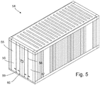
- Fig. 5 is a perspective view of a schematic conventional container seen from outside, such as e.g. a freight container or storage container, in the present case cube steel corrugated container 54.
- the container 54 e.g. has steel panel walls and a hinged steel double door 55, which includes a first hinged door 56 and a second hinged door 57.
- the lock device 1,2 seen in the previous figs. 1- 4 has been secured to the double door 55.
- Vertical door locking bars 58 are associated with the double door 55 and in co-operation with the cam keeper 59 of the door cam 60 at the bottom of the double door 55.
- Such containers are known to the person skilled in the art.
- Figs. 6 and 7 show the interlocking principle of the first lock part 1 and the second lock part 2 shown and described in relation to the previous figures on an open and on a closed double door 55, respectively, of the container 54 seen in fig. 5 .
- the first exterior part 3 is mounted on the first exterior face 61 of the first wall 56a of the first door 56
- the first interior part 4 is mounted on the first interior face 62 of the first wall 56a of said first door 56 by means of first bolt means 5a,5b traversing the first wall 56a of the first door 56 through an enforced first vertical frame part 63 of the first door 56 opposite its door hinge (not shown), only two bolts of the first bolt means are visible in figs. 6 and 7 .
- the second exterior part 42 is mounted on the second exterior face 64 of the second wall 57a of the second door 57
- the second interior part 43 is mounted on the second interior face 65 of said second door 57 by means of second bolt means 48 traversing the second wall 57a of the second door 57 through an enforced second vertical frame part 66 of the second door 57 opposite its door hinge (not shown), only one bolt of the second bolt means is visible in figs. 6 and 7 .
- the first bolt means 5 is screwed into the first exterior part 3 and externalised through the first plate 6 of the first interior part 4 and tightened to this first plate 6 by means of nuts 15a,15b,15c and washers 16a,16b,16c of which only two sets are visible in figs. 6 and 7 .
- the lock box 11 is mounted to the first plate 6, and the cylinder 13 of the lock is embedded in the first exterior part 3.
- the associated spindle 24,30 reaches through the first door 56 to operate the locking mechanism inside the lock box 11 to displace the lock bolt 12 laterally towards and through aligned first opening 20 of the first locking profile 7 of the first interior part 4 and through second opening 53 of the second locking profile 45 of the second interior part 42 when the double door 55 is closed, as seen in figs. 6 and 7 .
- the first door 56 has a free first front edge 67, which in the present case includes the enforced first vertical frame part 63.
- the second door 57 has a free second front edge 68, which in the present case includes the enforced second vertical frame part 66.
- a seal 69 such as a plastic or rubber gasket, serves to seal against water ingress when the double door 55 is closed, in that the seal 69 fills any gap between the free first front edge 67 and the free second front edge 68 in the double door's closed position.
- the first locking profile 7 protrudes laterally towards the web of the second locking profile 45 inside the container 54 so that the this web is located in the groove, cavity or gap 18 between the opposite legs 17a,17b of the first locking profile, whereby the opposite locking profiles 17,45 firmly interlock as a means to make any illegal or unauthorised opening of the container extremely difficult.
- Fig. 8 is a perspective view of an alternative second embodiment of the first interior part 70 of a first lock part, seen from different faces, and a second interior part 71 of a second lock part.
- Said alternative second embodiment of a first interior part 70 and of a second interior part 71 corresponds substantially to the previously described first embodiments of a first interior part 3 and a second interior part 42, and for like parts same reference numerals are used.
- the respective exterior parts 3,43 are similar as for the first embodiments.
- the second embodiment of a first interior part 70 differs in that the groove, cavity or gap 18 of the first locking profile 7 between the opposite legs 17a,17b is closed at least at opposite ends by opposite end plates 72a,72b.
- the height of the second locking profile 45 is selected to be substantially same or slightly smaller than the interior distance between the end plates 72a,72b, so that when the second locking profile 45 is moved from the open condition seen in fig. 7 to the closed condition seen in fig. 6 the end plates 72a,72b guides the second locking profile 45 inside the groove, cavity or gap 18 of the first locking profile 7.
- the lower end plate 72a expediently serves to support the bottom of the second locking profile 45 to avoid that any of the first door 56 and the second door 57 misalign, e.g. due to the very weight of the doors themselves making them skew or hang so that the opposite locking openings 20,53 are not suitably aligned for receiving the lock bolt 12 through both opposite locking openings 20,53.
- the second locking profile 45 has been given smooth free corners 73a,73b to facilitate insertion of the second locking profile 45 into the groove, cavity or gap 18 of the first locking profile 7.
- the end plates 72a,72b also improve structural integrity of the first interior part 4 by enforcing the transition between the first plate 6 and the first locking profile 7, including enforcing the edge 8.
- the container becomes difficult to open unauthorised and illegally.
- the interlocking female and male parts of the locking profiles with laterally inserted locking bolt when the lock is locked requires a specific sequence of actions for closing and opening the double door.
- the accessibility of the specific key is also required and the keyhole being the only part of the lock accessible from the exterior parts.
- the key cylinder is rebored, the locking bolt through the locking opening of engaging interlocking locking profiles prevents opening, or at least makes opening extremely difficult because an intruder don't have sufficient time to proceed with the break-in opening process before security systems or watchmen are alerted.
Landscapes
- Engineering & Computer Science (AREA)
- Structural Engineering (AREA)
- Lock And Its Accessories (AREA)
- Closures For Containers (AREA)
Description
- The present invention relates to a lock device for a double door, the lock device comprising a
- a first lock part for mounting on a first wall of a first door of the double door, which first lock part comprises a first exterior part and a first interior part,
- a second lock part for mounting on a second wall of a second door of the double door for locking together with the first lock part in closed position of the double door, which second lock part comprises a second exterior part and a second interior part, and
- a lock,
- the first lock part comprises a first bolt means having a first length selected to screw the first exterior part and the first interior part together through the first wall of the first door,
- the second lock part comprises a second bolt means having a second length selected to screw the second exterior part and the second interior part together through the second wall of the second door, and
- the first interior part has female interlocking and/or engagement means for engaging male interlocking and/or engagement means of the second interior part.
- In particular, the present invention relates to an anti-theft lock device for securing e.g. cargo, shipping or storage containers having double doors, however the lock device according to the present invention can be used on any device, compartment, room or unit to secure possessions and content.
- It is important that such a container and it's content arrives or is stored intact and without loss due to theft. The weakest part of such a container, especially when being used for storage, is the lock device. Most such lock devices do not come as an integral part of the container. Often the lock devices are mounted later by the end user and can have any level of strength. There are several types of lock devices. Cheaper lock devices tend to be weaker, while expensive lock devices can, but need not, be more secure. Some may even be completely ineffective in deterring thefts. For some conventional lock devices it will even be impossible to detect evidence of tampering until it is discovered that content is missing.
- An exemplary conventional lock device is a lock device box comprising a steel house that protects a padlock from being cut or broken in any way. By enclosing the padlock it makes the container much harder to break into and less attractive to thieves.
- One exemplary lock device box is a so-called "weld-on lock box" which the end user welds on the container doors. The weld-on lock box confines a padlock inside a weld-on house. Someone trying to break into the container would normally just cut the lock shank of the padlock, which padlock however is difficult accessible due to being hidden inside the small enclosed area of the weld-on house. A disadvantage of weld-on lock boxes is the requirement for welding equipment.
- Welding equipment is not needed in a "bolt-on lock device box" where a bolt on a lock box replaces the welding of the "weld-on lock box".
- Yet an alternative of a lock device is a "clamp-on lock device" designed specifically to clamp on the container's vertical locking bars and using a pin lock with a key. The conventional "clamp-on lock device" can be moved from container to container.
- From
FR 2 839 105 - From
US H 1766 is known a lock device with a dead bolt positioned in a single door. A frame with an opening is attached to the wall, where the opening can receive the dead bolt. - In a main aspect of the present invention is provided a lock device of the type mentioned in the opening paragraph that is easy to operate and position as protectively as possible.
- In a further aspect of the present invention is provided a lock device of the type mentioned in the opening paragraph that effectively deters break-ins and secures cargo and content.
- In a further aspect of the present invention is provided a lock device of the type mentioned in the opening paragraph that is difficult to cut with hand-operated tools.
- In a further aspect of the present invention is provided a lock device of the type mentioned in the opening paragraph that can be mounted fast and efficiently on existing and new containers, optionally be moved from one container to another.
- In a further aspect of the present invention is provided a lock device of the type mentioned in the opening paragraph that can be mounted without welding equipment.
- In a further aspect of the present invention is provided an improved lock device of the type mentioned in the opening paragraph.
- The novel and unique aspects, whereby these and other aspects are achieved according to the present invention, consist in that
- the first interior part is a first plate having the first locking profile provided on a first edge,
- the second interior part is a second plate having the second locking profile provided on a second edge opposite the first edge,
- which first locking profile and second locking profile are adapted to interlock and/or engage in the closed position of the double door, wherein
- the first locking profile protrudes substantially perpendicular from the first edge away from the first exterior part to define a locking groove or cavity along the first edge,
- the second locking profile protrudes substantially perpendicular from the second edge away from the second exterior part to define a locking protrusion along the second edge.
- For the present invention the term "container" refers to large containers for storage, cargo, shipping, freight etc., e.g. high cube steel containers. The double door can, but need not, be provided in or constitute the short end wall of the container, but other positions of the double door is not excluded. Means for tamper-proofing may also be provided.
- A conventional "bolt-on lock device box" also utilizes bolt means. The length of the bolt is selected so that it can pass through the container door to be fastened by a nut directly on the interior side of the container door, thus without interposed interior part as in the present invention. So the "bolt-on lock device box" differs from the present invention in not having an interior part of a lock part other than the nut, just an exterior part of a lock part to be mounted exterior to the container. The bolt means ensures that each lock part remains in fixed position on its associated door during opening and closing of the double door. Emphasize is thus made that for the present invention a suitable long bolt means is needed to reach through both the container door wall and the interior part. A further difference is that the female interlocking and/or engagement means engaging the male interlocking and/or engagement means of the respective interior parts result in that interlocking and/or engagement of the first door's first lock part and the second door's second lock part takes place inside the container, not outside the container as for conventional lock devices. Final anti-theft locking after closing the double door is done by actuating and locking the lock of the lock device.
- At least a part of the lock itself may be positioned on an interior part and being operable from outside the double door, e.g. from an exterior part outside a double door for a container. The initial interlocking and/or engagement operation of the double door takes place upon closing the double door. In doing so the first door with the female interlocking and/or engagement means is closed. Then the second door is closed so that the male interlocking and/or engagement means of the second interior part is inserted to engage and/or lock into the female interlocking and/or engagement means of the first interior part. Once the double door is closed the lock can be operated from outside the double door to finally securely lock said double door.
- The first locking profile and the second locking profile overlap to interlock and/or engage in the closed position of the double door. At least one of the first and second locking profiles may thus extend beyond the front edge of the opposite door on the backside of the double door when it is closed. The first locking profile that defines the female locking component may e.g. protrude laterally from the first plate towards the second locking profile over the backside of the second door.
- By arranging interlocking and/or engagement of the double door inside the container the locking of the double door becomes an extra anti-theft means in addition to the lock, because neither the interior part of the lock nor the first locking profile and the second locking profile are accessible to thieves. When an intruder try to pull open the locked double door the male protrusion of the second locking profile, which is positioned inside the locking cavity of the first locking profile, severely obstructs pivotability of the opposite individual doors, thereby making unauthorised opening even more difficult. The first plate and the second plate also expediently serve as washer plates for the respective first bolt means and second bolt means.
- Optionally the locking groove or cavity is closed at least at one of opposite ends by an end plate. Preferably the locking groove or cavity of the first locking profile is closed at opposite ends by an upper end plate and a lower end plate, respectively. The end plates provide guidance for inserting the second locking profile inside the groove or cavity of the first locking profile. The lower end plate advantageously further serves for keeping the first and second lock openings aligned. For example double doors of metal storage containers are very heavy and may dislocate vertically. Only a small vertical dislocation can cause dislocation of the alignment of the locking openings. When the second door is closed the lower end of the second locking profile plate can rest on the lower plate thereby keeping the alignment of the opposite locking opening required for the proper function of the lock device.
- The first locking profile may e.g. be a U-profile and the second locking profile may be a web fitting between the legs of the U-profile of the first locking profile. In the closed position of the double door the legs of the U-profile fit as tightly as possible, e.g. with a clearance on opposite sides of the web of less than 0.5 cm, alternatively less than 0.3 cm, alternatively less than 0.2 cm.
- In a preferred embodiment the first lock part may comprise the lock, which lock is adapted for displacing a lock bolt through aligned first and second lock openings. These aligned first and second lock openings may be a first lock opening of the female first locking profile and/or engagement means and a second lock opening of the male second locking profile and/or engagement means. The lock bolt through these aligned openings are thus hidden from outside the closed double door by being provided on the backside of the double door. The lock bolt inside the container, and thus the lock, is operated from outside the container to block separation and movement of the opposite interlocked and/or engaged interior parts when the lock bolt passes through both lock openings. Preferably the first lock opening is provided in the first locking profile and the second lock opening is provided in the second locking profile so that when these locking profiles interlock and/or engage the lock bolt traverse both locking profiles inside the closed container and is complete inaccessible to be cut by any tool or otherwise manipulated.
- One or both of the first exterior part and the second exterior part is/are solid metal block(s), preferably heavy metal block(s), such as steel blocks which are in intimate contact with the respective container door once mounted. Such heavy blocks required massive tool capacity, effort and time to demount unauthorised, e.g. to cut off or just deteriorate, and even if the thieve is lucky to cut off any of the first exterior part and the second exterior part the interlocking of the interior parts are still a hindrance for the thieve to open the double door. The first interior part and the second interior part may be made of metal as well.
- A further advantage of this embodiment is that the block design can provide good and safe accommodation of more or less embedded parts of the lock. If for example the lock has a lock cylinder the keyway can beneficially be embedded in the first exterior part of the first lock part, simply by drilling an accommodation hole and place the keyway in the accommodation hole with a spindle protruding through the respective door to operate a locking mechanism provided on or in relation to the surface of the first plate that faces away from the first door, thus when e.g. the double door is mounted on a container the locking mechanism is mounted on the face of the first plate facing inside the container. The only part of the keyway exposed to the environment when the double door is closed is the
keyhole 13a, and preferably the cylinder and thus the keyway is mounted retracted inside the block of the first exterior part so that even thekeyhole 13a is displaced axially inside the accommodation hole. The rather large mass of metal surrounding the cylinder and keyway then also protects the cylinder and keyway from unintended tampering and physical access. - The spindle can advantageous be adapted to have adjustable length, so that one lock device can be fitted on different doors having various thickness.
- In an alternative embodiment the lock is electronic, in which embodiment no parts or components at all of the electronic lock are provided on any of the exterior parts. The lock is exclusively provided behind the double door and no keyhole and cylinder needed in the first exterior part. Such an electronic lock can lock and un-lock the double door from both inside and outside the double door.
- A suitable means for mounting and keeping the lock device correctly on the double door may be configured so that the first bolt means includes a first bolt and a first nut, and the second bolt means includes a second bolt and a second nut. Optionally the first bolt and/or the second bolt are threaded and/or the first nut and/or the second nut is/are a screw nut.
- In the simple embodiment the first exterior part and the second exterior part of the lock device may have exterior curved faces, e.g. to make a smooth transition towards the exterior surface of the respective door when the lock device is mounted on the double door, thereby making the visual design more elegant.
- In one embodiment the second door may be the active door and the first door be the passive door. Which door is the passive or the active depends on which door the first locking profile and the second locking profile are provided on, in that the female locking profile needs to be on the passive part to cooperate with the male locking profile upon closing the double door.
- Accordingly, the first door may be configured as the second door, and the second door be configured as the first door.
- The present invention also relate to a method of mounting the lock device described above on a double door, e.g. the double door of a container.
- The method comprises the steps of
- drilling one or more first holes in the first door for inserting a first bolt means and a spindle,
- drilling one or more second holes in the second door for inserting the second bolt means,
- assembling the first lock part by placing the first exterior part on the exterior side of the first door and the first interior part on the interior side of the first door and tightening the first bolt means so that the first interior part and first exterior part are secured to the first door, and
- assembling the second lock part by placing the second exterior part on the exterior side of the second door and the second interior part on the interior side of the second door and tightening the second bolt means so that the second interior part and second exterior part are secured to the second door.
- The spindle of the lock device extends from the first exterior part through the first door to operate the lock mechanism on the first interior part to displace the lock bolt through the aligned first and second openings of the respective first and second locking profiles.
- The lock device according to the present invention can be used to lock up other kinds of enclosures and compartments than containers as defined above. The lock device can be used for locking together opposite doors of any closure arrangement for a compartment, including double doors for gateways, entrance points, fencings, etc. This list is not exhaustive and other uses are foreseen within the scope of the present invention.
- The invention will now be described in further details below with reference to the accompanying drawing in which,
-
fig. 1 is a perspective exploded view of the first lock part seen from the first exterior part, without the lock, -
fig. 2 is a perspective exploded view of the first lock part seen from the first interior part, and including an exploded view of the lock components of the lock, -
fig. 3 is a perspective exploded view of the second lock part seen from the second exterior part, -
fig. 4 is a perspective exploded view of the second lock part seen from the second interior part, -
fig. 5 is a perspective view of a storage container having a closed double door being provided with the lock device seen in the previous figures, -
fig. 6 is a principle sketch of the interlocking of the lock device mounted on a closed double door of the storage container seen infig. 5 in closed condition, -
fig. 7 shows the same but with an open double door, and -
fig. 8 shows, in perspective, an alternative embodiment of a first interior part of a first lock part and a second interior part of a second lock part. - In the following detailed description it is assumed by way of example that the first lock part is mounted on the left door of a storage container when viewed from outside the container, and the second lock part is mounted on the right door of the storage container when viewed from outside the container. In this embodiment the left door is the first door and the right door is the second door. However, this arrangement shall not be seen as limiting the versatility of mounting the lock parts. So in an alternative embodiment the first lock part can be mounted on the left door and the second lock part be mounted on the right door of the storage container when viewed from outside the container. Furthermore, the lock device is only by way of example shown on a storage container. Emphasise is made that the lock device can be used on other objects having double doors.
-
Fig. 1 is a perspective exploded view of the first lock part 1 of alock device 1,2 seen from the firstexterior part 3 opposite the firstinterior part 4, andfig. 2 shows the first lock part 1 from the firstexterior part 4. Theclosed lock device 1,2 is shown and described in subsequent drawings. - The first
exterior part 3 is a solid steel block wherein a first bolt means 5 is secured to protrude towards the firstinterior lock part 4 through appropriate holes drilled, or otherwise provided, in a first door (not shown). The firstinterior lock part 4 includes afirst plate 6, which has a femalefirst locking profile 7, in form of a U-profile, in extension of afirst edge 8 of thefirst plate 6. In case the double door is a container double door having vertically hinged doors thefirst edge 8 is typically vertical when thelock device 1,2 is mounted to the double door and the container is placed on the ground, and so is the femalefirst locking profile 7. Afirst contact face 9 of thefirst plate 6 is mounted onto the first door, and an oppositelock support face 10 serves for supporting and mounting alock box 11 of the lock. Thelock box 11 has alock bolt 12, in the present case a square bolt, to be operated by means of a key for acylinder 13 of a cylinder lock, e.g. similarly to a conventional cylinder lock, which is mounted in the firstexterior lock part 3, as will be described further below. - When the first
exterior lock part 3 is mounted on the first door of the double door thelong bolts exterior lock part 3 pass through drilled holes in the first door and further through three alignedfirst holes first plate 6 of the firstinterior lock part 4. Then the firstexterior lock part 3 is firmly secured to saidfirst plate 6 by means of three associated sets offirst washers first nuts lock support face 10 of thefirst plate 6, thereby sandwiching the wall of the double door in-between the firstexterior lock part 3 and the firstinterior lock part 4. The position on thefirst plate 6 of the assembled first bolt means 5 and the co-operatingfirst washers first nuts lock box 11 and has no impact on the operation and function of the lock. This assembled fastening means 5;15a,15b,15c; 16a,16b,16c ensures solid and reliable mounting of the first lock part 1 on the first door. This position of assembled first bolt means 5,first washers first nuts lock device 1,2. - The U-profiled female
first locking profile 7 is defined by afirst leg 17a that extends from thefirst edge 8 of thefirst plate 6 into asecond leg 17b via the bottom wall of the U-profile 7 to define a groove, cavity orgap 18 for receiving a male part of a second lock part, as will be explained in further details below with references to the further figures. Arecess 19 of thefirst leg 17a serves to accommodate afront part 20 of thelock box 12, whichfront part 20 is inserted laterally in thefirst leg 17a, so that thelock bolt 12 can reciprocate inside a first lock opening 20 traversing thefirst leg 17a via therecess 19. Thelock box 11 can be mounted to thelock support face 10 of thefirst plate 6 using any appropriate method, including welding to thefirst plate 6 and/or screwing or force-fitting. In the present embodiment first through-holes 20a',20b' disposed vertically on opposite sides of the first lock opening 20 serve for receiving first lock box screws 20a", 20b" to firmly further fasten thelock box 11 laterally in therecess 19 of saidfirst lock profile 7. Axially thelock box 11 is fastened to theplate 6 by means of second lock box screws 39a', 39b' in second through-holes 39a", 39b" made in thefirst plate 6 and further to the lock box by means of third through-holes 40a', 40b'. - The
cylinder 13 of the cylinder lock is mounted in acylinder lock hole 21 in the firstexterior lock part 3 so as to be encased, embedded and hidden for thieves and intruders. Only akeyhole 13a is visible and accessible from outside the firstexterior lock part 3. Preferably, thecylinder lock hole 21 has a reduced diameter at the exterior face of the firstexterior part 3 to only provide for access to akeyhole 13a, which keyhole 13a preferably is retracted from said exterior face of the firstexterior part 3. - In addition to the
cylinder 13, the cylinder lock includes aholder 22 for holding anenlarged head 23 of a first elongated andextended spindle part 24 in operatively engagement with thecylinder 13. To that purpose, additionally theenlarged head 23 has ahead recess 25 for engaging amale extension 26 on thecylinder 13, so that when the key is turned, so is the first elongated andextended spindle part 24. Theenlarged head 23 of thisfirst spindle part 24 has an extension in form of an elongatedsplit neck part 27. This splitneck part 27 has anaxial slit 28, which in the embodiment shown extends from theenlarged head 23 to thefree end 29 of thesplit neck part 27, to allow for inserting a malesecond spindle part 30 provided on thelock box 11 so that the length of the combined spindle can be adjusted to the thickness of different first doors. Thesecond spindle part 30 is operatively connected to thelock bolt 12, so that when the malesecond spindle part 30 is engaged inside the axially extending secondsplit neck part 27, thelock bolt 12 can be displaced laterally to pass in and out of at the alignedfirst lock opening 20 and second lock opening upon turning a key. Although thespindle lock bolt 12 can be operatively connected via a conventional locking mechanism. - The engaging
first spindle part 24 andsecond spindle part 30 are mounted inside apipe guide piece 31 to prevent disengagement when the combined engagedspindle structure lock bolt 12 laterally through thefirst lock opening 20 and second lock opening to lock the double door. Theguide pipe piece 31 reaches through aguide hole 32 in thefirst plate 6 so that oneend 31a of theguide pipe piece 31 abuts theenlarged head 23 of thefirst spindle part 24 and theopposite end 31b of theguide pipe piece 31 reaches towards, optionally into, thelock box 11. Thepipe guide piece 31 further holds on to the engagingspindle parts spindle parts spindle parts spindle parts - The engaging
male extension 26 of thecylinder 13 located in thehead recess 25 and theenlarged head 23 of thefirst spindle part 24 are rotatably arranged in acomplementary cavity 22a of theholder 22 to further prevent disengagement ofmale extension 26 andhead recess 25. - The assembled
cylinder 13,holder 22, andenlarged head 23 of thefirst spindle part 24 are mounted insidecylinder lock hole 21 of the first exterior part and held in place inside saidcylinder lock hole 21 by means of afirst cover plate 33, which has a firstcover plate hole 34 for exiting thesplit neck part 27 of thefirst spindle part 24. First screws 35 serve to screw thefirst cover plate 33, theholder 22, and thecylinder 13 together using holes provided fro that purpose in the respective componet. The diameter of the firstcover plate hole 34 is smaller than the diameter of theenlarged head 23, so that when the assembly offirst cover plate 33,holder 22, andcylinder 13 is secured to the firstexterior lock part 3 by means ofsecond screws 36, this difference in diameter serves as an additional means to make sure that theenlarged head 23 stays put behind thefirst cover plate 33. - A second cover plate 37 serves substantially similar purpose at the
lock box 11, thus it secures thesecond spindle part 30 firmly to thelock box 11. Prior to being mounted to thefirst plate 6 thesecond spindle part 30, that protrudes from thelock box 11 towards thefirst spindle part 24, is passed through a secondcover part hole 38 of the second cover plate 37. Hereafter the second cover plate 37 is fastened to thelock box 11 by means ofthird screws lock box holes third screws lock box 11 by means of corresponding small nuts 41. - The extra lengths and engagement of the
long spindle parts -
Fig. 3 is a perspective exploded view of thesecond lock part 2 seen from the secondexterior part 42, andfig. 4 is a perspective exploded view of thesecond lock part 2 seen from the secondinterior part 43. - The second
exterior part 42 is also a solid steel block wherein a second bolt means 48 is secured to protrude towards the secondinterior lock part 43 through appropriate holes drilled, or otherwise provided, in a second door (not shown). - The second
interior lock part 43 includes asecond plate 44, which has a malesecond locking profile 45, in form of a protruding web in extension of asecond edge 46 of thesecond plate 44, so that the secondinterior lock part 2 has an L-shape. In case the double door is a container double door having vertically hinged doors thesecond edge 46 is typically vertical, similarly to thefirst edge 8. Asecond contact face 47 of thesecond plate 44 is mounted in contact with the second door. When the double door is closed the malesecond locking profile 45 and the femalefirst locking profile 7 engage to interlock. When the first door is open the femalefirst locking profile 7 is exposed, so that when the second door is closed the malesecond locking profile 45 is turned into locking engagement with the groove, cavity orgap 18 between theopposite legs first locking profile 7. - The second
exterior lock part 42 is mounted on the second door by means of twolong bolts exterior lock part 42. These second bolt means 48 passes through appropriate drilled holes in the second door and further through two alignedsecond holes second plate 44 of the secondinterior lock part 43. Then the secondexterior lock part 42 is firmly secured to saidsecond plate 44 by means of two associated sets of correspondingsecond washers 50a,50bc andsecond nuts free face 52 opposite thesecond contact face 47 of thesecond plate 44 thereby sandwiching the wall of the second door of the double door in-between the secondexterior lock part 42 and the secondinterior lock part 43. - The male
second locking profile 45 has a second lock opening 53 that in the closed position of the double door is aligned with the first lock opening 20 of thefirst locking profile 7 so that thelock bolt 12 can pass through said alignedlock openings -
Fig. 5 is a perspective view of a schematic conventional container seen from outside, such as e.g. a freight container or storage container, in the present case cube steel corrugatedcontainer 54. Thecontainer 54 e.g. has steel panel walls and a hinged steeldouble door 55, which includes a first hingeddoor 56 and a second hingeddoor 57. Thelock device 1,2 seen in the previousfigs. 1- 4 has been secured to thedouble door 55. Vertical door locking bars 58 are associated with thedouble door 55 and in co-operation with thecam keeper 59 of thedoor cam 60 at the bottom of thedouble door 55. Such containers are known to the person skilled in the art. -
Figs. 6 and7 show the interlocking principle of the first lock part 1 and thesecond lock part 2 shown and described in relation to the previous figures on an open and on a closeddouble door 55, respectively, of thecontainer 54 seen infig. 5 . - The first
exterior part 3 is mounted on the firstexterior face 61 of thefirst wall 56a of thefirst door 56, and the firstinterior part 4 is mounted on the firstinterior face 62 of thefirst wall 56a of saidfirst door 56 by means of first bolt means 5a,5b traversing thefirst wall 56a of thefirst door 56 through an enforced firstvertical frame part 63 of thefirst door 56 opposite its door hinge (not shown), only two bolts of the first bolt means are visible infigs. 6 and7 . The secondexterior part 42 is mounted on the secondexterior face 64 of thesecond wall 57a of thesecond door 57, and the secondinterior part 43 is mounted on the secondinterior face 65 of saidsecond door 57 by means of second bolt means 48 traversing thesecond wall 57a of thesecond door 57 through an enforced secondvertical frame part 66 of thesecond door 57 opposite its door hinge (not shown), only one bolt of the second bolt means is visible infigs. 6 and7 . - The first bolt means 5 is screwed into the first
exterior part 3 and externalised through thefirst plate 6 of the firstinterior part 4 and tightened to thisfirst plate 6 by means of nuts 15a,15b,15c andwashers figs. 6 and7 . As explained above thelock box 11 is mounted to thefirst plate 6, and thecylinder 13 of the lock is embedded in the firstexterior part 3. The associatedspindle first door 56 to operate the locking mechanism inside thelock box 11 to displace thelock bolt 12 laterally towards and through aligned first opening 20 of thefirst locking profile 7 of the firstinterior part 4 and throughsecond opening 53 of thesecond locking profile 45 of the secondinterior part 42 when thedouble door 55 is closed, as seen infigs. 6 and7 . - As seen best in
fig. 7 , thefirst door 56 has a free firstfront edge 67, which in the present case includes the enforced firstvertical frame part 63. Thesecond door 57 has a free secondfront edge 68, which in the present case includes the enforced secondvertical frame part 66. Along the second front edge 68 aseal 69, such as a plastic or rubber gasket, serves to seal against water ingress when thedouble door 55 is closed, in that theseal 69 fills any gap between the free firstfront edge 67 and the free secondfront edge 68 in the double door's closed position. - The
first locking profile 7 protrudes laterally towards the web of thesecond locking profile 45 inside thecontainer 54 so that the this web is located in the groove, cavity orgap 18 between theopposite legs -
Fig. 8 is a perspective view of an alternative second embodiment of the firstinterior part 70 of a first lock part, seen from different faces, and a secondinterior part 71 of a second lock part. - Said alternative second embodiment of a first
interior part 70 and of a secondinterior part 71 corresponds substantially to the previously described first embodiments of a firstinterior part 3 and a secondinterior part 42, and for like parts same reference numerals are used. Thus the respectiveexterior parts - The second embodiment of a first
interior part 70 differs in that the groove, cavity orgap 18 of thefirst locking profile 7 between theopposite legs opposite end plates second locking profile 45 is selected to be substantially same or slightly smaller than the interior distance between theend plates second locking profile 45 is moved from the open condition seen infig. 7 to the closed condition seen infig. 6 theend plates second locking profile 45 inside the groove, cavity orgap 18 of thefirst locking profile 7. When thedouble door 55 is locked thelower end plate 72a expediently serves to support the bottom of thesecond locking profile 45 to avoid that any of thefirst door 56 and thesecond door 57 misalign, e.g. due to the very weight of the doors themselves making them skew or hang so that theopposite locking openings lock bolt 12 through both opposite lockingopenings second locking profile 45 has been given smoothfree corners second locking profile 45 into the groove, cavity orgap 18 of thefirst locking profile 7. - The
end plates interior part 4 by enforcing the transition between thefirst plate 6 and thefirst locking profile 7, including enforcing theedge 8. - By providing the lock itself inside the container, the container becomes difficult to open unauthorised and illegally. The interlocking female and male parts of the locking profiles with laterally inserted locking bolt when the lock is locked requires a specific sequence of actions for closing and opening the double door. In case the lock is key operated the accessibility of the specific key is also required and the keyhole being the only part of the lock accessible from the exterior parts. Even if the key cylinder is rebored, the locking bolt through the locking opening of engaging interlocking locking profiles prevents opening, or at least makes opening extremely difficult because an intruder don't have sufficient time to proceed with the break-in opening process before security systems or watchmen are alerted.
Claims (15)
- A lock device (1,2) for a double door (55), the lock device (1,2) comprising- a first lock part (1) for mounting on a first wall (56a) of a first door (56) of the double door (55), which first lock part (1) comprises a first exterior part (3) and a first interior part (4),- a second lock part (2) for mounting on a second wall (57a) of a second door (57) of the double door (55) for locking together with the first lock part (1) in closed position of the double door (55), which second lock part (2) comprises a second exterior part (42) and a second interior part (43), and- a lock,- the first lock part (1) comprises a first bolt means (5,5a,5b,5c) having a first length selected to screw the first exterior part (3) and the first interior part (4) together through the first wall (56a) of the first door (56),- the second lock part (2) comprises a second bolt means (48,48a,48b) having a second length selected to screw the second exterior part (42) and the second interior part (43) together through the second wall (57a) of the second door (57), and- the first interior part (4) has female first locking profile and/or engagement means (7) for engaging a male second locking profile and/or engagement means (45) of the second interior part (43),characterised in that- the first interior part (4) has a first plate (6) having the first locking profile (7) provided on a first edge (8),- the second interior part (43) has a second plate (44) having the second locking profile (45) provided on a second edge (46),- which first locking profile (7) and second locking profile (45) are adapted to interlock and/or engage in the closed position of the double door (55), wherein- the first locking profile (7) protrudes substantially perpendicular from the first edge (8) away from the first exterior part (3) to define a locking groove, cavity or gap (18) along the first edge (8),- the second locking profile (45) protrudes substantially perpendicular from the second edge (46) away from the second exterior part (42) to define a locking protrusion along the second edge (46).
- A lock device (1,2) according to claim 1, characterised in that at least a part of the lock is positioned on an interior part (4,43) and being operable from outside the double door (55).
- A lock device (1,2) according to claims 1 or 2, characterised in that the locking groove, cavity or gap (18) is closed at least at one of opposite ends by an end plate (72a, 72b) .
- A lock device (1,2) according to any of claims 1, 2 or 3 characterised in that the first locking profile (7) is a U-profile and the second locking profile (45) is a web fitting between the legs (17a,17b) of the U-profile of the first locking profile (7).
- A lock device (1,2) according to claims 3 or 4, characterised in that the first lock part (1) comprises the lock, which lock is adapted for displacing a lock bolt (12) through aligned lock openings being a first lock opening (20) of the female first locking profile and/or engagement means (7) and a second lock opening (53) of the male second locking profile and/or engagement means (45), preferably the first lock opening (20) is provided in the first locking profile (7) and the second locking opening (53) is provided in the second locking profile (45).
- A lock device (1,2) according to any of the preceding claims 1 - 5, characterised in that one or both of the first exterior part (3) and the second exterior part (42) is/are solid metal block(s), preferably heavy metal block(s).
- A lock device (1,2) according to any of the preceding claims 3 - 6, characterised in that the lock comprises- a lock cylinder (13) having a keyway and being embedded in the first lock part (1), and- a locking mechanism (11,12,13) is provided on or in relation to the surface (10) of the first plate (6) that faces away from the first door (56), which locking mechanism is in operative communication with the lock cylinder (13) via a spindle (24,27).
- A lock device (1,2) according to claim 7, characterised in that the spindle (24,27) has adjustable length.
- A lock device (1,2) according to any of the preceding claims 1 - 6, characterised in that the lock is electronic.
- A lock device (1,2) according to any of the preceding claims 1 - 9, characterised in that the first bolt means (5) includes a first bolt (5a,5b,5c) and a first nut (15a,15b,15c), and the second bolt means (48) includes a second bolt (48a,48b) and a second nut (50a,50b), optionally the first bolt (5a,5b,5c) and/or the second bolt (48a,48b) are threaded and/or the first nut (15a,15b,15c) and/or the second nut is/are a screw nut (50a, 50b) .
- A lock device (1,2) according to any of the preceding claims 1 - 10, characterised in that an exterior face of an exterior part (3,42) facing away from the double door (55) when the lock device (1,2) is mounted on the double door (55) is curved towards the exterior surface of the respective door (56,57).
- A lock device (1,2) according to any of the preceding claims 1 - 11, characterised in that the second door (57) is the active door and the first door (56) is the passive door.
- A lock device (1,2) according to any of the preceding claims 1 - 12, characterised in that the first door (56) is configured as the second door (57), and the second door (57) is configured as the first door (56).
- A method of mounting the lock device (1,2) according to any of the preceding claims 1 - 13 on a double door (55) of a container (54) comprises the steps of- drilling one or more first holes in the first door (56) for inserting a first bolt means (5,5a,5b,5c) and a spindle (24,27),- drilling one or more second holes in the second door (57) for inserting the second bolt means (48,48a,48b),- assembling the first lock part (1) by placing the first exterior part (3) on the exterior side of the first door (56) and the first interior part (4) on the interior side of the first door (56) and tightening the first bolt means (5,5a,5b,5c) so that the first interior part (4) and first exterior part (3) are secured to the first door (56), and- assembling the second lock part (2) by placing the second exterior part (42) on the exterior side of the second door (57) and the second interior part (43) on the interior side of the second door (57) and tightening the second bolt means (48,48a,48b) so that the second interior part (43) and second exterior part (42) are secured to the second door (57).
- Use of the lock device (1,2) defined in any of the preceding claims 1 - 13 for locking together opposite doors (56,57) of a double door (55) of any closure arrangement for a compartment or enclosure, including double doors for containers, gateways, entrance points, and fencings.
Priority Applications (4)
| Application Number | Priority Date | Filing Date | Title |
|---|---|---|---|
| DK14199241.2T DK3034720T3 (en) | 2014-12-19 | 2014-12-19 | A double door locking device and its applications |
| ES14199241T ES2746753T3 (en) | 2014-12-19 | 2014-12-19 | A locking device for a double door and its uses |
| EP14199241.2A EP3034720B8 (en) | 2014-12-19 | 2014-12-19 | A lock device for a double door and uses thereof |
| PCT/EP2015/080049 WO2016097020A2 (en) | 2014-12-19 | 2015-12-16 | An anti-theft lock device for a double door and uses thereof |
Applications Claiming Priority (1)
| Application Number | Priority Date | Filing Date | Title |
|---|---|---|---|
| EP14199241.2A EP3034720B8 (en) | 2014-12-19 | 2014-12-19 | A lock device for a double door and uses thereof |
Publications (3)
| Publication Number | Publication Date |
|---|---|
| EP3034720A1 EP3034720A1 (en) | 2016-06-22 |
| EP3034720B1 true EP3034720B1 (en) | 2019-06-26 |
| EP3034720B8 EP3034720B8 (en) | 2019-10-23 |
Family
ID=52146246
Family Applications (1)
| Application Number | Title | Priority Date | Filing Date |
|---|---|---|---|
| EP14199241.2A Active EP3034720B8 (en) | 2014-12-19 | 2014-12-19 | A lock device for a double door and uses thereof |
Country Status (4)
| Country | Link |
|---|---|
| EP (1) | EP3034720B8 (en) |
| DK (1) | DK3034720T3 (en) |
| ES (1) | ES2746753T3 (en) |
| WO (1) | WO2016097020A2 (en) |
Families Citing this family (1)
| Publication number | Priority date | Publication date | Assignee | Title |
|---|---|---|---|---|
| CN109326060B (en) * | 2018-11-02 | 2020-09-29 | 国网四川省电力公司广安供电公司 | Remote intelligent monitoring system for electric power self-service payment terminal |
Citations (1)
| Publication number | Priority date | Publication date | Assignee | Title |
|---|---|---|---|---|
| EP2955301A1 (en) * | 2014-06-13 | 2015-12-16 | Georgios Thomaidis | Container lock |
Family Cites Families (4)
| Publication number | Priority date | Publication date | Assignee | Title |
|---|---|---|---|---|
| GB9302918D0 (en) * | 1993-02-13 | 1993-03-31 | Hardware & Systems Patents Ltd | Security fitting |
| USH1766H (en) * | 1995-02-17 | 1999-01-05 | The United States Of America As Represented By The Secretary Of The Navy | Integrated astragal |
| FR2839105A1 (en) * | 2002-04-25 | 2003-10-31 | Milivoye Zivanovic | Locking of door panels for utility vehicles with double doors, uses sleeves on both door panels with bolt passing through both to lock door, and head of bolt carrying a lock that secures it inside one sleeve |
| DE102008032525B4 (en) * | 2008-07-10 | 2010-09-09 | Gerald Baumann | Burglar alarm for freight containers |
-
2014
- 2014-12-19 ES ES14199241T patent/ES2746753T3/en active Active
- 2014-12-19 EP EP14199241.2A patent/EP3034720B8/en active Active
- 2014-12-19 DK DK14199241.2T patent/DK3034720T3/en active
-
2015
- 2015-12-16 WO PCT/EP2015/080049 patent/WO2016097020A2/en active Application Filing
Patent Citations (1)
| Publication number | Priority date | Publication date | Assignee | Title |
|---|---|---|---|---|
| EP2955301A1 (en) * | 2014-06-13 | 2015-12-16 | Georgios Thomaidis | Container lock |
Also Published As
| Publication number | Publication date |
|---|---|
| EP3034720B8 (en) | 2019-10-23 |
| ES2746753T3 (en) | 2020-03-06 |
| EP3034720A1 (en) | 2016-06-22 |
| WO2016097020A2 (en) | 2016-06-23 |
| WO2016097020A3 (en) | 2016-10-27 |
| DK3034720T3 (en) | 2019-09-09 |
Similar Documents
| Publication | Publication Date | Title |
|---|---|---|
| CA2752853C (en) | Locking system for a storage container | |
| US7047774B1 (en) | Side security device for roll-up doors | |
| US6915670B2 (en) | Security device for roll-up doors | |
| US5621387A (en) | Box | |
| US20210340796A1 (en) | Electrical panelboard guard with coupled members | |
| US11274472B2 (en) | Hasp assembly for a hidden-shackle padlock | |
| US4883294A (en) | Tamper-proof locking device | |
| EP3034720B1 (en) | A lock device for a double door and uses thereof | |
| US20220403682A1 (en) | Storage box latch system and security features | |
| US20050103065A1 (en) | Protective cover for locking devices | |
| GB2111586A (en) | Staples for padlocks | |
| US4413492A (en) | Deadbolt lock protector | |
| GB2449287A (en) | Security apparatus using a padlock | |
| KR100648073B1 (en) | A building shutting prevention window locking unit | |
| WO2012027784A1 (en) | A locking device for a door for an enclosure | |
| AU2011295627B2 (en) | A locking device for a door for an enclosure | |
| US5524943A (en) | Security device | |
| US20140246871A1 (en) | Lock hasp apparatus | |
| JP2004124555A (en) | Crime preventing function enhanced door | |
| WO2015156732A1 (en) | Locking device | |
| JP3104940U (en) | Protector and protector kit for automatic transaction equipment | |
| WO1992014017A1 (en) | Storage unit locking device | |
| JP2007045474A (en) | Container | |
| JP2005060996A (en) | Structure of double lid of vessel | |
| WO1989002019A1 (en) | Lock combination |
Legal Events
| Date | Code | Title | Description |
|---|---|---|---|
| PUAI | Public reference made under article 153(3) epc to a published international application that has entered the european phase |
Free format text: ORIGINAL CODE: 0009012 |
|
| AK | Designated contracting states |
Kind code of ref document: A1 Designated state(s): AL AT BE BG CH CY CZ DE DK EE ES FI FR GB GR HR HU IE IS IT LI LT LU LV MC MK MT NL NO PL PT RO RS SE SI SK SM TR |
|
| AX | Request for extension of the european patent |
Extension state: BA ME |
|
| STAA | Information on the status of an ep patent application or granted ep patent |
Free format text: STATUS: REQUEST FOR EXAMINATION WAS MADE |
|
| 17P | Request for examination filed |
Effective date: 20161208 |
|
| RAX | Requested extension states of the european patent have changed |
Extension state: BA Payment date: 20161208 Extension state: ME Payment date: 20161208 |
|
| RBV | Designated contracting states (corrected) |
Designated state(s): AL AT BE BG CH CY CZ DE DK EE ES FI FR GB GR HR HU IE IS IT LI LT LU LV MC MK MT NL NO PL PT RO RS SE SI SK SM TR |
|
| STAA | Information on the status of an ep patent application or granted ep patent |
Free format text: STATUS: EXAMINATION IS IN PROGRESS |
|
| 17Q | First examination report despatched |
Effective date: 20180611 |
|
| RIC1 | Information provided on ipc code assigned before grant |
Ipc: E05B 17/20 20060101AFI20180906BHEP Ipc: E05B 9/08 20060101ALN20180906BHEP Ipc: E05C 7/04 20060101ALN20180906BHEP Ipc: E05B 83/02 20140101ALI20180906BHEP |
|
| RIC1 | Information provided on ipc code assigned before grant |
Ipc: E05B 17/20 20060101AFI20181121BHEP Ipc: E05C 7/04 20060101ALN20181121BHEP Ipc: E05B 9/08 20060101ALN20181121BHEP Ipc: E05B 83/02 20140101ALI20181121BHEP |
|
| GRAP | Despatch of communication of intention to grant a patent |
Free format text: ORIGINAL CODE: EPIDOSNIGR1 |
|
| STAA | Information on the status of an ep patent application or granted ep patent |
Free format text: STATUS: GRANT OF PATENT IS INTENDED |
|
| INTG | Intention to grant announced |
Effective date: 20190108 |
|
| GRAS | Grant fee paid |
Free format text: ORIGINAL CODE: EPIDOSNIGR3 |
|
| GRAA | (expected) grant |
Free format text: ORIGINAL CODE: 0009210 |
|
| STAA | Information on the status of an ep patent application or granted ep patent |
Free format text: STATUS: THE PATENT HAS BEEN GRANTED |
|
| AK | Designated contracting states |
Kind code of ref document: B1 Designated state(s): AL AT BE BG CH CY CZ DE DK EE ES FI FR GB GR HR HU IE IS IT LI LT LU LV MC MK MT NL NO PL PT RO RS SE SI SK SM TR |
|
| AX | Request for extension of the european patent |
Extension state: BA ME |
|
| REG | Reference to a national code |
Ref country code: GB Ref legal event code: FG4D |
|
| REG | Reference to a national code |
Ref country code: CH Ref legal event code: EP |
|
| REG | Reference to a national code |
Ref country code: AT Ref legal event code: REF Ref document number: 1148460 Country of ref document: AT Kind code of ref document: T Effective date: 20190715 |
|
| REG | Reference to a national code |
Ref country code: IE Ref legal event code: FG4D |
|
| REG | Reference to a national code |
Ref country code: DE Ref legal event code: R096 Ref document number: 602014049008 Country of ref document: DE |
|
| REG | Reference to a national code |
Ref country code: DK Ref legal event code: T3 Effective date: 20190905 |
|
| REG | Reference to a national code |
Ref country code: NL Ref legal event code: FP |
|
| GRAT | Correction requested after decision to grant or after decision to maintain patent in amended form |
Free format text: ORIGINAL CODE: EPIDOSNCDEC |
|
| REG | Reference to a national code |
Ref country code: CH Ref legal event code: PK Free format text: BERICHTIGUNG B8 |
|
| REG | Reference to a national code |
Ref country code: SE Ref legal event code: TRGR |
|
| RAP2 | Party data changed (patent owner data changed or rights of a patent transferred) |
Owner name: SERVIAL CC APS |
|
| PG25 | Lapsed in a contracting state [announced via postgrant information from national office to epo] |
Ref country code: LT Free format text: LAPSE BECAUSE OF FAILURE TO SUBMIT A TRANSLATION OF THE DESCRIPTION OR TO PAY THE FEE WITHIN THE PRESCRIBED TIME-LIMIT Effective date: 20190626 Ref country code: HR Free format text: LAPSE BECAUSE OF FAILURE TO SUBMIT A TRANSLATION OF THE DESCRIPTION OR TO PAY THE FEE WITHIN THE PRESCRIBED TIME-LIMIT Effective date: 20190626 Ref country code: AL Free format text: LAPSE BECAUSE OF FAILURE TO SUBMIT A TRANSLATION OF THE DESCRIPTION OR TO PAY THE FEE WITHIN THE PRESCRIBED TIME-LIMIT Effective date: 20190626 |
|
| REG | Reference to a national code |
Ref country code: NO Ref legal event code: T2 Effective date: 20190626 |
|
| REG | Reference to a national code |
Ref country code: LT Ref legal event code: MG4D |
|
| PG25 | Lapsed in a contracting state [announced via postgrant information from national office to epo] |
Ref country code: BG Free format text: LAPSE BECAUSE OF FAILURE TO SUBMIT A TRANSLATION OF THE DESCRIPTION OR TO PAY THE FEE WITHIN THE PRESCRIBED TIME-LIMIT Effective date: 20190926 Ref country code: RS Free format text: LAPSE BECAUSE OF FAILURE TO SUBMIT A TRANSLATION OF THE DESCRIPTION OR TO PAY THE FEE WITHIN THE PRESCRIBED TIME-LIMIT Effective date: 20190626 Ref country code: GR Free format text: LAPSE BECAUSE OF FAILURE TO SUBMIT A TRANSLATION OF THE DESCRIPTION OR TO PAY THE FEE WITHIN THE PRESCRIBED TIME-LIMIT Effective date: 20190927 Ref country code: LV Free format text: LAPSE BECAUSE OF FAILURE TO SUBMIT A TRANSLATION OF THE DESCRIPTION OR TO PAY THE FEE WITHIN THE PRESCRIBED TIME-LIMIT Effective date: 20190626 |
|
| REG | Reference to a national code |
Ref country code: AT Ref legal event code: MK05 Ref document number: 1148460 Country of ref document: AT Kind code of ref document: T Effective date: 20190626 |
|
| PG25 | Lapsed in a contracting state [announced via postgrant information from national office to epo] |
Ref country code: RO Free format text: LAPSE BECAUSE OF FAILURE TO SUBMIT A TRANSLATION OF THE DESCRIPTION OR TO PAY THE FEE WITHIN THE PRESCRIBED TIME-LIMIT Effective date: 20190626 Ref country code: EE Free format text: LAPSE BECAUSE OF FAILURE TO SUBMIT A TRANSLATION OF THE DESCRIPTION OR TO PAY THE FEE WITHIN THE PRESCRIBED TIME-LIMIT Effective date: 20190626 Ref country code: AT Free format text: LAPSE BECAUSE OF FAILURE TO SUBMIT A TRANSLATION OF THE DESCRIPTION OR TO PAY THE FEE WITHIN THE PRESCRIBED TIME-LIMIT Effective date: 20190626 Ref country code: PT Free format text: LAPSE BECAUSE OF FAILURE TO SUBMIT A TRANSLATION OF THE DESCRIPTION OR TO PAY THE FEE WITHIN THE PRESCRIBED TIME-LIMIT Effective date: 20191028 Ref country code: CZ Free format text: LAPSE BECAUSE OF FAILURE TO SUBMIT A TRANSLATION OF THE DESCRIPTION OR TO PAY THE FEE WITHIN THE PRESCRIBED TIME-LIMIT Effective date: 20190626 Ref country code: SK Free format text: LAPSE BECAUSE OF FAILURE TO SUBMIT A TRANSLATION OF THE DESCRIPTION OR TO PAY THE FEE WITHIN THE PRESCRIBED TIME-LIMIT Effective date: 20190626 |
|
| PG25 | Lapsed in a contracting state [announced via postgrant information from national office to epo] |
Ref country code: IS Free format text: LAPSE BECAUSE OF FAILURE TO SUBMIT A TRANSLATION OF THE DESCRIPTION OR TO PAY THE FEE WITHIN THE PRESCRIBED TIME-LIMIT Effective date: 20191026 Ref country code: SM Free format text: LAPSE BECAUSE OF FAILURE TO SUBMIT A TRANSLATION OF THE DESCRIPTION OR TO PAY THE FEE WITHIN THE PRESCRIBED TIME-LIMIT Effective date: 20190626 Ref country code: IT Free format text: LAPSE BECAUSE OF FAILURE TO SUBMIT A TRANSLATION OF THE DESCRIPTION OR TO PAY THE FEE WITHIN THE PRESCRIBED TIME-LIMIT Effective date: 20190626 |
|
| REG | Reference to a national code |
Ref country code: ES Ref legal event code: FG2A Ref document number: 2746753 Country of ref document: ES Kind code of ref document: T3 Effective date: 20200306 |
|
| PG25 | Lapsed in a contracting state [announced via postgrant information from national office to epo] |
Ref country code: TR Free format text: LAPSE BECAUSE OF FAILURE TO SUBMIT A TRANSLATION OF THE DESCRIPTION OR TO PAY THE FEE WITHIN THE PRESCRIBED TIME-LIMIT Effective date: 20190626 |
|
| PG25 | Lapsed in a contracting state [announced via postgrant information from national office to epo] |
Ref country code: PL Free format text: LAPSE BECAUSE OF FAILURE TO SUBMIT A TRANSLATION OF THE DESCRIPTION OR TO PAY THE FEE WITHIN THE PRESCRIBED TIME-LIMIT Effective date: 20190626 |
|
| PG25 | Lapsed in a contracting state [announced via postgrant information from national office to epo] |
Ref country code: IS Free format text: LAPSE BECAUSE OF FAILURE TO SUBMIT A TRANSLATION OF THE DESCRIPTION OR TO PAY THE FEE WITHIN THE PRESCRIBED TIME-LIMIT Effective date: 20200224 |
|
| REG | Reference to a national code |
Ref country code: DE Ref legal event code: R097 Ref document number: 602014049008 Country of ref document: DE |
|
| PLBE | No opposition filed within time limit |
Free format text: ORIGINAL CODE: 0009261 |
|
| STAA | Information on the status of an ep patent application or granted ep patent |
Free format text: STATUS: NO OPPOSITION FILED WITHIN TIME LIMIT |
|
| PG2D | Information on lapse in contracting state deleted |
Ref country code: IS |
|
| 26N | No opposition filed |
Effective date: 20200603 |
|
| PG25 | Lapsed in a contracting state [announced via postgrant information from national office to epo] |
Ref country code: SI Free format text: LAPSE BECAUSE OF FAILURE TO SUBMIT A TRANSLATION OF THE DESCRIPTION OR TO PAY THE FEE WITHIN THE PRESCRIBED TIME-LIMIT Effective date: 20190626 Ref country code: MC Free format text: LAPSE BECAUSE OF FAILURE TO SUBMIT A TRANSLATION OF THE DESCRIPTION OR TO PAY THE FEE WITHIN THE PRESCRIBED TIME-LIMIT Effective date: 20190626 |
|
| PG25 | Lapsed in a contracting state [announced via postgrant information from national office to epo] |
Ref country code: IE Free format text: LAPSE BECAUSE OF NON-PAYMENT OF DUE FEES Effective date: 20191219 |
|
| PG25 | Lapsed in a contracting state [announced via postgrant information from national office to epo] |
Ref country code: CY Free format text: LAPSE BECAUSE OF FAILURE TO SUBMIT A TRANSLATION OF THE DESCRIPTION OR TO PAY THE FEE WITHIN THE PRESCRIBED TIME-LIMIT Effective date: 20190626 |
|
| PG25 | Lapsed in a contracting state [announced via postgrant information from national office to epo] |
Ref country code: MT Free format text: LAPSE BECAUSE OF FAILURE TO SUBMIT A TRANSLATION OF THE DESCRIPTION OR TO PAY THE FEE WITHIN THE PRESCRIBED TIME-LIMIT Effective date: 20190626 Ref country code: HU Free format text: LAPSE BECAUSE OF FAILURE TO SUBMIT A TRANSLATION OF THE DESCRIPTION OR TO PAY THE FEE WITHIN THE PRESCRIBED TIME-LIMIT; INVALID AB INITIO Effective date: 20141219 |
|
| PG25 | Lapsed in a contracting state [announced via postgrant information from national office to epo] |
Ref country code: MK Free format text: LAPSE BECAUSE OF FAILURE TO SUBMIT A TRANSLATION OF THE DESCRIPTION OR TO PAY THE FEE WITHIN THE PRESCRIBED TIME-LIMIT Effective date: 20190626 |
|
| P01 | Opt-out of the competence of the unified patent court (upc) registered |
Effective date: 20230331 |
|
| PGFP | Annual fee paid to national office [announced via postgrant information from national office to epo] |
Ref country code: GB Payment date: 20231211 Year of fee payment: 10 |
|
| PGFP | Annual fee paid to national office [announced via postgrant information from national office to epo] |
Ref country code: SE Payment date: 20231211 Year of fee payment: 10 Ref country code: NO Payment date: 20231212 Year of fee payment: 10 Ref country code: NL Payment date: 20231219 Year of fee payment: 10 Ref country code: LU Payment date: 20231219 Year of fee payment: 10 Ref country code: FR Payment date: 20231211 Year of fee payment: 10 Ref country code: FI Payment date: 20231211 Year of fee payment: 10 Ref country code: DK Payment date: 20231211 Year of fee payment: 10 Ref country code: DE Payment date: 20231211 Year of fee payment: 10 |
|
| PGFP | Annual fee paid to national office [announced via postgrant information from national office to epo] |
Ref country code: BE Payment date: 20231219 Year of fee payment: 10 |
|
| PGFP | Annual fee paid to national office [announced via postgrant information from national office to epo] |
Ref country code: ES Payment date: 20240102 Year of fee payment: 10 |
|
| PGFP | Annual fee paid to national office [announced via postgrant information from national office to epo] |
Ref country code: CH Payment date: 20240102 Year of fee payment: 10 |