EP3031679A1 - Method and system for electronic brake actuator detection - Google Patents
Method and system for electronic brake actuator detection Download PDFInfo
- Publication number
- EP3031679A1 EP3031679A1 EP15198579.3A EP15198579A EP3031679A1 EP 3031679 A1 EP3031679 A1 EP 3031679A1 EP 15198579 A EP15198579 A EP 15198579A EP 3031679 A1 EP3031679 A1 EP 3031679A1
- Authority
- EP
- European Patent Office
- Prior art keywords
- eba
- voltage
- ebac
- electronic brake
- brake control
- Prior art date
- Legal status (The legal status is an assumption and is not a legal conclusion. Google has not performed a legal analysis and makes no representation as to the accuracy of the status listed.)
- Granted
Links
- 238000000034 method Methods 0.000 title claims abstract description 25
- 238000001514 detection method Methods 0.000 title description 4
- 230000003213 activating effect Effects 0.000 claims abstract description 6
- 230000005355 Hall effect Effects 0.000 claims description 13
- 230000008901 benefit Effects 0.000 description 6
- 230000004044 response Effects 0.000 description 6
- 238000005259 measurement Methods 0.000 description 2
- 230000015654 memory Effects 0.000 description 2
- 206010056508 Acquired epidermolysis bullosa Diseases 0.000 description 1
- 230000006978 adaptation Effects 0.000 description 1
- 238000010276 construction Methods 0.000 description 1
- 230000008878 coupling Effects 0.000 description 1
- 238000010168 coupling process Methods 0.000 description 1
- 238000005859 coupling reaction Methods 0.000 description 1
- 229920006245 ethylene-butyl acrylate Polymers 0.000 description 1
Images


Classifications
-
- B—PERFORMING OPERATIONS; TRANSPORTING
- B60—VEHICLES IN GENERAL
- B60T—VEHICLE BRAKE CONTROL SYSTEMS OR PARTS THEREOF; BRAKE CONTROL SYSTEMS OR PARTS THEREOF, IN GENERAL; ARRANGEMENT OF BRAKING ELEMENTS ON VEHICLES IN GENERAL; PORTABLE DEVICES FOR PREVENTING UNWANTED MOVEMENT OF VEHICLES; VEHICLE MODIFICATIONS TO FACILITATE COOLING OF BRAKES
- B60T8/00—Arrangements for adjusting wheel-braking force to meet varying vehicular or ground-surface conditions, e.g. limiting or varying distribution of braking force
- B60T8/17—Using electrical or electronic regulation means to control braking
- B60T8/1701—Braking or traction control means specially adapted for particular types of vehicles
- B60T8/1703—Braking or traction control means specially adapted for particular types of vehicles for aircrafts
-
- B—PERFORMING OPERATIONS; TRANSPORTING
- B60—VEHICLES IN GENERAL
- B60T—VEHICLE BRAKE CONTROL SYSTEMS OR PARTS THEREOF; BRAKE CONTROL SYSTEMS OR PARTS THEREOF, IN GENERAL; ARRANGEMENT OF BRAKING ELEMENTS ON VEHICLES IN GENERAL; PORTABLE DEVICES FOR PREVENTING UNWANTED MOVEMENT OF VEHICLES; VEHICLE MODIFICATIONS TO FACILITATE COOLING OF BRAKES
- B60T8/00—Arrangements for adjusting wheel-braking force to meet varying vehicular or ground-surface conditions, e.g. limiting or varying distribution of braking force
- B60T8/17—Using electrical or electronic regulation means to control braking
- B60T8/172—Determining control parameters used in the regulation, e.g. by calculations involving measured or detected parameters
-
- G—PHYSICS
- G01—MEASURING; TESTING
- G01D—MEASURING NOT SPECIALLY ADAPTED FOR A SPECIFIC VARIABLE; ARRANGEMENTS FOR MEASURING TWO OR MORE VARIABLES NOT COVERED IN A SINGLE OTHER SUBCLASS; TARIFF METERING APPARATUS; MEASURING OR TESTING NOT OTHERWISE PROVIDED FOR
- G01D5/00—Mechanical means for transferring the output of a sensing member; Means for converting the output of a sensing member to another variable where the form or nature of the sensing member does not constrain the means for converting; Transducers not specially adapted for a specific variable
- G01D5/12—Mechanical means for transferring the output of a sensing member; Means for converting the output of a sensing member to another variable where the form or nature of the sensing member does not constrain the means for converting; Transducers not specially adapted for a specific variable using electric or magnetic means
- G01D5/14—Mechanical means for transferring the output of a sensing member; Means for converting the output of a sensing member to another variable where the form or nature of the sensing member does not constrain the means for converting; Transducers not specially adapted for a specific variable using electric or magnetic means influencing the magnitude of a current or voltage
- G01D5/142—Mechanical means for transferring the output of a sensing member; Means for converting the output of a sensing member to another variable where the form or nature of the sensing member does not constrain the means for converting; Transducers not specially adapted for a specific variable using electric or magnetic means influencing the magnitude of a current or voltage using Hall-effect devices
-
- G—PHYSICS
- G01—MEASURING; TESTING
- G01R—MEASURING ELECTRIC VARIABLES; MEASURING MAGNETIC VARIABLES
- G01R15/00—Details of measuring arrangements of the types provided for in groups G01R17/00 - G01R29/00, G01R33/00 - G01R33/26 or G01R35/00
- G01R15/04—Voltage dividers
-
- B—PERFORMING OPERATIONS; TRANSPORTING
- B60—VEHICLES IN GENERAL
- B60T—VEHICLE BRAKE CONTROL SYSTEMS OR PARTS THEREOF; BRAKE CONTROL SYSTEMS OR PARTS THEREOF, IN GENERAL; ARRANGEMENT OF BRAKING ELEMENTS ON VEHICLES IN GENERAL; PORTABLE DEVICES FOR PREVENTING UNWANTED MOVEMENT OF VEHICLES; VEHICLE MODIFICATIONS TO FACILITATE COOLING OF BRAKES
- B60T2270/00—Further aspects of brake control systems not otherwise provided for
- B60T2270/40—Failsafe aspects of brake control systems
- B60T2270/406—Test-mode; Self-diagnosis
Definitions
- Aircraft like any other vehicle, rely on braking systems to slow down or stop.
- an electronic brake actuator EBA
- EBAC electronic brake actuator controller
- Wiring throughout the aircraft may enable signals to pass between the EBAC and EBA.
- EBAC electronic brake actuator controller
- any reference to singular includes plural embodiments, and any reference to more than one component or step may include a singular embodiment or step.
- any reference to attached, fixed, connected or the like may include permanent, removable, temporary, partial, full and/or any other possible attachment option.
- any reference to without contact (or similar phrases) may also include reduced contact or minimal contact.
- EBA 83a has a 16 pin input/output interface in FIG. 2 .
- Pins 2, 10, and 11 provide phase A, phase B, and phase C power, respectively, to operate a three-phase actuator.
- EBA 83a is configured to operate using a resolver for positioning information.
- Pin 15 provides excitement to the resolver.
- Pins 4, 14, and 5 provide position information.
- Pins 7 and 8 provide a load sensor signal.
Landscapes
- Engineering & Computer Science (AREA)
- Transportation (AREA)
- Mechanical Engineering (AREA)
- Physics & Mathematics (AREA)
- General Physics & Mathematics (AREA)
- Aviation & Aerospace Engineering (AREA)
- Braking Systems And Boosters (AREA)
Abstract
Description
- The present disclosure relates to braking systems, and, more specifically, to automatic detection and operation of an electronic brake actuator.
- Aircraft, like any other vehicle, rely on braking systems to slow down or stop. In many braking systems, an electronic brake actuator (EBA) may be controlled remotely by an electronic brake actuator controller (EBAC). Wiring throughout the aircraft may enable signals to pass between the EBAC and EBA. As aircrafts age, many may be retrofitted with newer, improved systems. However, changing one component in the brake system, for example, may result in rewiring and replacement of other components in the brake system for compatibility.
- In various embodiments, an electronic brake system may comprise a brake control unit (BCU), an electronic brake actuation controller (EBAC) electrically coupled to the BCU, and an electronic brake actuator (EBA) electrically coupled to the EBAC. The EBAC is configured to detect a type of the EBA based on an electric signal from the EBA.
- In various embodiments, a voltage sensing circuit may be configured to detect a voltage of the electric signal. The EBA may have a pull-up resistor electrically coupled to the voltage sensing circuit. The EBA may have a load sensor electrically coupled to the voltage sensing circuit. A sense resistor may be electrically coupled in series with the EBA. The voltage sensing circuit may be configured to detect the voltage at a node between the EBA and the sense resistor. The EBAC is configured to use a first circuit based on the voltage and the first circuit is compatible with Hall Effect sensors. A circuit configured to use a second circuit based on the voltage and the second circuit is compatible with a resolver.
- In various embodiments, a method of detecting an EBA may comprise the steps of measuring a voltage on an input pin connected to an EBAC, determining an EBA type connected to the input pin based on the voltage, and activating circuitry and software in the EBAC corresponding to the EBA type.
- In various embodiments, the method may also include measuring the voltage with a voltage sensing circuit. The voltage may be measured using a voltage divider. The method may also include the steps of removing the EBA from the input pin, connecting a second EBA to the input pin, determining a second EBA type connected to the input pin based on a second voltage, and activating the circuitry and software in the EBAC corresponding to the second EBA type. A pull-up resistor of the second EBA may be selected to produce the second voltage. The voltage may be measured between a sense resistor of the EBAC and the pull-up resistor of the second EBA. The method may also comprise providing power to a Hall Effect sensor of the second EBA.
- The foregoing features and elements may be combined in various combinations without exclusivity, unless expressly indicated otherwise. These features and elements as well as the operation thereof will become more apparent in light of the following description and the accompanying drawings. It should be understood, however, the following description and drawings are intended to be exemplary in nature and non-limiting.
- The subject matter of the present disclosure is particularly pointed out and distinctly claimed in the concluding portion of the specification. A more complete understanding of the present disclosure, however, may best be obtained by referring by way of example only to the detailed description and claims when considered in connection with the figures, wherein like numerals denote like elements.
-
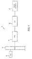
FIG. 1 illustrates an exemplary brake control system, in accordance with various embodiments; -
FIG. 2 illustrates input/output panels from different electronic brake actuators configured to use the same wiring, in accordance with various embodiments; -
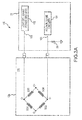
FIG. 3A illustrates a load cell and EBA detection system for an EBAC to detect a voltage, in accordance with various embodiments; -
FIG. 3B illustrates a load cell and EBA detection system for an EBAC to detect a current, in accordance with various embodiments; and -
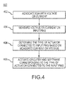
FIG. 4 illustrates a method for detecting the type of EBA installed in a braking system, in accordance with various embodiments. - The detailed description of exemplary embodiments herein makes reference to the accompanying drawings, which show exemplary embodiments by way of illustration. While these exemplary embodiments are described in sufficient detail to enable those skilled in the art to practice the exemplary embodiments of the disclosure, it should be understood that other embodiments may be realized and that logical changes and adaptations in design and construction may be made in accordance with this disclosure and the teachings herein. Thus, the detailed description herein is presented for purposes of illustration only and not limitation. The scope of the disclosure is defined by the appended claims. For example, the steps recited in any of the method or process descriptions may be executed in any order and are not necessarily limited to the order presented.
- Furthermore, any reference to singular includes plural embodiments, and any reference to more than one component or step may include a singular embodiment or step. Also, any reference to attached, fixed, connected or the like may include permanent, removable, temporary, partial, full and/or any other possible attachment option. Additionally, any reference to without contact (or similar phrases) may also include reduced contact or minimal contact.
- With reference to
Fig. 1 , abrake control system 80 may have an electrical brake actuation controller 81 ("EBAC"), an electric brake actuator 83 ("EBA"), and abrake assembly 85 in accordance to various embodiments. The EBAC 81 may provide force commands to the EBA 83, directing the EBA 83 to cause thebrake assembly 85 to mechanically operate, driving the aircraft brakes to provide braking power. For example, the EBAC 81 may be responsible for executing brake actuation instructions received via a logical connection, such as a controller area network ("CAN")bus 87, from other aircraft systems, such as a brake control unit 89 ("BCU"). In this manner, the brakes may be operated. In further embodiments, the EBAC 81 may provide force commands to more than one EBA 83, for example, a first EBA and a second EBA, or any number of EBAs, in order to operate more than one brake assembly, for example, a first brake assembly and a second brake assembly in concert. - As discussed herein, various aspects of the present disclosure may be implemented in various logical units of a processor having a non-transitory memory. In various embodiments, various aspects may be implemented in multiple processors and/or memories. For example, the disclosed system may be implemented within the EBAC 81. Various aspects of the disclosed system may be implemented within the EBAC 81 and/or the EBA 83 and/or BCU 89.
- In various embodiments, different models of EBA 83 with different modes of operation may be installed in
brake control system 80. For example, one type of EBA 83 may use a resolver to identify the angular position of the electric motor in EBA 83. Another type of EBA 83 may use Hall Effect sensors to identify the angular position of the electric motor in EBA 83. Some types of EBA 83 may include load sensors that output a load signal in voltage, while other types of EBA 83 may include load cells that output a load signal in current. The input/output interfaces of different types of EBA 83 may use input/output pins for different signals. - With reference to
FIG. 2 , the input/output pins of different types of electronic brake actuators may be configured to be controlled by the same EBAC (e.g., EBAC 81 inFIG. 1 ), in accordance with various embodiments. An interface may comprise pins that convey electrical signals into or out of an EBA or EBAC. For example, EBA 83a has a 16 pin input/output interface inFIG. 2 .Pins EBA 83a is configured to operate using a resolver for positioning information.Pin 15 provides excitement to the resolver.Pins Pins EBA 83a may provide a load sensor voltage. The load sensor voltage may be from 0-20 mV.Pins Pins Pin 9grounds EBA 83a. -
EBA 83b is a different type of EBA thanEBA 83a. In that regard,EBA 83b has different power inputs and a different mode of operation.EBA 83b operates by providing the angular position of the brake actuator via Hall Effect sensors, whereasEBA 83a uses a resolver.EBA 83b may, however, share many input/output pins withEBA 83a. For example, pins 2, 10, and 11 may still provide phase A, phase B, and phase C power, respectively.EBA 83b may provide friction data onpins EBA 83b may also be grounded bypin 9. - In various embodiments,
EBA 83b may differ fromEBA 83a in thatpin 8 ofEBA 83b may provide a load cell current. For example,pin 8 ofEBA 83b my carry a load cell signal in the form of 4-20 mA current whilepin 7 is dormant. In that regard,EBA 83a may output a signal encoded in a load sensor voltage andEBA 83b may output a signal encoded in a load sensor current. Other pins ofEBA 83b may also differ from the pins inEBA 83a. For example,pin 1 ofEBA 83b may be a power input for the Hall Effect sensor and load cell.Pins EBA 83b used to provide the position of the motor inEBA 83b.Pin 5 may provide the voltage return for the DC power provided to Hall Effect sensors viapin 1. - With reference to
FIG. 3A , an EBAC 81 configured to detect whetherEBA 83a orEBA 83b (fromFIG. 2 ) are connected to EBAC 81 based on the signal of pin 6 (fromFIG. 2 ).EBAC 81 andEBA 83a are electrically connected inbrake system 140. In various embodiments,EBA 83a may includeload sensor 110.Load sensor 110 may output a signal from the E+ and E- terminals. For example, E+ may be attached to pin 1 ofEBA 83a as shown inFIG. 2 . Similarly, E- may be attached to pin 6 ofEBA 83a as shown inFIG. 2 . Thus,pin 1 may be coupled to the load cell andHall power circuitry 152 of EBAC 81 viaconduit 158.Pin 6 may be coupled tovoltage sense circuitry 154 throughconduit 160. The voltage difference between E+ and E- may be measured inEBAC 81. Asense resistor 156 may be coupled between E- and ground and may operate as a voltage divider whenEBA 83a is connected to EBAC 81. In that regard, the voltage drop acrosssense resistor 156 is indicative of the voltage drop throughload sensor 110. In various embodiments, the voltage measured byvoltage sense circuitry 154 in response to startup withEBA 83a connected may be from 0-40 mV. - With reference to
FIG. 3B , anEBAC 81 may be configured to detect whenEBA 83b is connected to EBAC 81 inelectronic brake system 142, in accordance with various embodiments. The circuitry inEBAC 81 inFIG. 3B is identical to that inFIG. 3A , including load cell &Hall power circuitry 152,voltage sense circuitry 154, andsense resistor 156.EBA 83b includesload cell 130. Internally,EBA 83b haspin 1 connected to load cell &Hall power circuitry 152 throughconduit 158. Load cell &Hall power circuitry 152 may be modified to provide DC power to both Hall Effect sensors (whenEBA 83b using Hall Effect sensors is connected to EBAC 81) and the load cell since both use a DC power supply. The load cell is connected to pin 1 at E+. A pull-upresistor 132 may extend between the node at E+ andvoltage sense circuitry 154.Pin 6 may be coupled tovoltage sense circuitry 154 throughconduit 160. Pull-upresistor 132 may be selected to have a different voltage drop across pull-upresistor 132 than the voltage drop acrossload sensor 110 ofFIG. 3A .Sense resistor 156 may form a voltage divider. The resistance ofsense resistor 156 may be chosen and is thus known. Thus, the voltage measured atvoltage sense circuitry 154 may indicate that eitherEBA 83b is connected or thatEBA 83a (as shown inFIG. 3A ) is connected. - In various embodiments, EBAC may activate different circuitry and software in response to detecting
EBA 83a orEBA 83b. With reference toFIG. 4 , amethod 400 for detecting and activating the correct circuitry in accordance with various embodiments is shown. Each type of EBA (83a or 83b) to be connected to EBAC 81 is associated with a current or voltage (Step 402).EBAC 81 measures the voltage or current on input pins (Step 404). The measurements may be taken using circuitry as shown inFIGs. 3A and3B . The voltage measured whenEBA 83a is connected to EBAC 81 may be different than the voltage measured whenEBA 83b is connected to EBAC 81. The measured voltages can be predicted or chosen by selecting the resistance values for pull-upresistor 132 orsense resistor 156. The measurement and check may be executed each time an aircraft is started. - In various embodiments,
EBAC 81 may determine the type of actuator connected to input pins based on the measured current or voltage (Step 406). IfEBA 83a is connected, then the voltage value read across sense resistor 156 (coupled to pin 6 ofEBA 83a) may correspond to a voltage divider circuit using the load cell equivalent resistance and the sense resistor. IfEBA 83b is connected, then the voltage value read across sense resistor 156 (coupled to pin 6 ofEBA 83b) corresponds to a voltage divider circuit using the pull up resistor and the sense resistor. For example,voltage sense circuitry 154 may measure a voltage of 5-35 mV in response toEBA 83a connected to EBAC 81.Voltage sense circuitry 154 may measure a voltage of 3 V or more in response toEBA 83b connected to EBAC 81. Thus,EBAC 81 may determine thatEBA 83b is connected in response tovoltage sense circuitry 154 measuring a voltage of 5 V at startup.EBAC 81 may then activate circuitry and software inEBAC 81 corresponding to the type of actuator that is connected to the input pins (Step 408). In that regard, the circuitry and software may be matched to the type of actuator detected. Continuing the above example,EBAC 81 may activate circuitry to controlEBA 83b (rather thanEBA 83a) in response to determining thatEBA 83b is connected to EBAC 81. Active circuitry inEBAC 81 may vary, for example, based on whether the EBA uses Hall Effect sensors or a resolver to indicate angular motor position. - In various embodiments,
EBAC 81 automatically detects the type of EBA connected and activates the correct circuitry and software to control the connected EBA. Different actuators may be connected to EBAC 81 using the same input wires, as shown inFIG. 2 , for different purposes. - Benefits and other advantages have been described herein with regard to specific embodiments. Furthermore, the connecting lines shown in the various figures contained herein are intended to represent exemplary functional relationships and/or physical couplings between the various elements. It should be noted that many alternative or additional functional relationships or physical connections may be present in a practical system. However, the benefits, advantages, and any elements that may cause any benefit or advantage to occur or become more pronounced are not to be construed as critical, required, or essential features or elements of the disclosure. The scope of the disclosure is accordingly to be limited by nothing other than the appended claims, in which reference to an element in the singular is not intended to mean "one and only one" unless explicitly so stated, but rather "one or more." Moreover, where a phrase similar to "at least one of A, B, or C" is used in the claims, it is intended that the phrase be interpreted to mean that A alone may be present in an embodiment, B alone may be present in an embodiment, C alone may be present in an embodiment, or that any combination of the elements A, B and C may be present in a single embodiment; for example, A and B, A and C, B and C, or A and B and C.
- Systems, methods and apparatus are provided herein. In the detailed description herein, references to "various embodiments", "one embodiment", "an embodiment", "an example embodiment", etc., indicate that the embodiment described may include a particular feature, structure, or characteristic, but every embodiment may not necessarily include the particular feature, structure, or characteristic. Moreover, such phrases are not necessarily referring to the same embodiment. Further, when a particular feature, structure, or characteristic is described in connection with an embodiment, it is submitted that it is within the knowledge of one skilled in the art to affect such feature, structure, or characteristic in connection with other embodiments whether or not explicitly described. After reading the description, it will be apparent to one skilled in the relevant art(s) how to implement the disclosure in alternative embodiments.
- Furthermore, no element, component, or method step in the present disclosure is intended to be dedicated to the public regardless of whether the element, component, or method step is explicitly recited in the claims. As used herein, the terms "comprises", "comprising", or any other variation thereof, are intended to cover a non-exclusive inclusion, such that a process, method, article, or apparatus that comprises a list of elements does not include only those elements but may include other elements not expressly listed or inherent to such process, method, article, or apparatus.
Claims (15)
- An electronic brake control system (80), comprising:a brake control unit (89) (BCU);an electronic brake actuation controller (81) (EBAC) electrically coupled to the BCU (89); andan electronic brake actuator (83) (EBA) electrically coupled to the EBAC (81), wherein the EBAC (81) is configured to detect a type of the EBA (83) based on an electrical signal from the EBA.
- The electronic brake control system of claim 1, wherein the EBAC (81) further comprises a voltage sensing circuit configured to detect a voltage of the electrical signal.
- The electronic brake control system of claim 2, wherein the EBA (83) has a pull-up resistor electrically coupled to the voltage sensing circuit.
- The electronic brake control system of claim 2, wherein the EBA (83) has a load sensor electrically coupled to the voltage sensing circuit.
- The electronic brake control system of claim 2, further comprising a sense resistor electrically coupled in series with the EBA (83).
- The electronic brake control system of claim 5, wherein the voltage sensing circuit is configured to detect the voltage at a node between the EBA (83) and the sense resistor.
- The electronic brake control system of claim 5, wherein the EBAC (81) is configured to use a first circuit based on the voltage and the first circuit is compatible with a Hall Effect sensor.
- The electronic brake control system of claim 7, further comprising a circuit configured to use a second circuit based on the voltage and the second circuit is compatible with a resolver.
- A method of detecting an electronic brake actuator (83) (EBA), comprising:measuring at least one of a voltage or a current on an input pin connected to an electronic brake actuation controller (81) (EBAC);determining an EBA (83) type connected to the input pin based on the voltage or current; andactivating circuitry and software in the EBAC (81) corresponding to the EBA (83) type.
- The method of claim 9, wherein the voltage is measured by a voltage sensing circuit.
- The method of claim 10, wherein the voltage is measured using a voltage divider.
- The method of claim 9, further comprising:removing the EBA (83) from the input pin;connecting a second EBA (83 b) to the input pin;determining a second EBA (83 b) type connected to the input pin based on at least one of a second voltage or a second current; andactivating the circuitry and software in the EBAC (81) corresponding to the second EBA (83 b) type.
- The method of claim 12, further comprising selecting a pull-up resistor of the second EBA (83 b) to produce the second voltage.
- The method of claim 13, wherein the second voltage is measured between a sense resistor of the EBAC (81) and the pull-up resistor of the second EBA (83 b).
- The method of claim 12, further comprising providing power to a Hall Effect sensor of the second EBA (83 b).
Applications Claiming Priority (1)
| Application Number | Priority Date | Filing Date | Title |
|---|---|---|---|
| US14/564,480 US9975530B2 (en) | 2014-12-09 | 2014-12-09 | Method and system for electronic brake actuator detection |
Publications (2)
| Publication Number | Publication Date |
|---|---|
| EP3031679A1 true EP3031679A1 (en) | 2016-06-15 |
| EP3031679B1 EP3031679B1 (en) | 2019-10-02 |
Family
ID=55027246
Family Applications (1)
| Application Number | Title | Priority Date | Filing Date |
|---|---|---|---|
| EP15198579.3A Active EP3031679B1 (en) | 2014-12-09 | 2015-12-09 | Method and system for electronic brake actuator detection |
Country Status (2)
| Country | Link |
|---|---|
| US (1) | US9975530B2 (en) |
| EP (1) | EP3031679B1 (en) |
Families Citing this family (3)
| Publication number | Priority date | Publication date | Assignee | Title |
|---|---|---|---|---|
| US9975530B2 (en) * | 2014-12-09 | 2018-05-22 | Goodrich Corporation | Method and system for electronic brake actuator detection |
| KR102492487B1 (en) * | 2018-08-16 | 2023-01-27 | 현대모비스 주식회사 | Apparatus for braking of vehicle and method thereof |
| CN111103478B (en) * | 2019-11-22 | 2022-06-28 | 中国人民解放军总参谋部第六十研究所 | Steering engine automatic detection equipment for unmanned helicopter |
Citations (2)
| Publication number | Priority date | Publication date | Assignee | Title |
|---|---|---|---|---|
| US20080154470A1 (en) * | 2006-12-21 | 2008-06-26 | Goranson Pete T | System and methods for an electric brake actuation overdrive feature in an aircraft electric brake system |
| US20130241527A1 (en) * | 2011-08-29 | 2013-09-19 | Control4 Corporation | Systems and methods for inductive load switching |
Family Cites Families (13)
| Publication number | Priority date | Publication date | Assignee | Title |
|---|---|---|---|---|
| US4222615A (en) * | 1977-12-09 | 1980-09-16 | The Bendix Corporation | Low voltage inhibit for adaptive braking system |
| US5888212A (en) * | 1997-06-26 | 1999-03-30 | Mauch, Inc. | Computer controlled hydraulic resistance device for a prosthesis and other apparatus |
| US6586927B2 (en) * | 2001-08-16 | 2003-07-01 | Delphi Technologies, Inc. | Hall effect position sensing in a powered parking brake system |
| US6752474B1 (en) * | 2003-05-06 | 2004-06-22 | Lynn M. Olberding | System and method for managing electric brakes |
| US7023163B2 (en) * | 2003-11-20 | 2006-04-04 | Siemens Building Technologies | Fail-safe electric actuator using high voltage capacitors |
| EP1751446B1 (en) * | 2004-06-04 | 2010-02-24 | Goodrich Corporation | Electric brake position and force sensing and control |
| US8149102B1 (en) * | 2008-03-27 | 2012-04-03 | Memsic Transducer Systems Co., Ltd. | Reconfigurable interface operable with multiple types of sensors and actuators |
| US9150201B2 (en) * | 2008-11-25 | 2015-10-06 | Cequent Performance Products, Inc. | Universal trailer mounted proportional brake controller |
| US9093106B2 (en) * | 2013-04-05 | 2015-07-28 | Rohm Co., Ltd. | Motor drive device, magnetic disk storage device, and electronic appliance |
| US9142248B2 (en) * | 2013-04-05 | 2015-09-22 | Rohm Co., Ltd. | Motor drive device, magnetic disk storage device, and electronic device |
| US9054607B2 (en) * | 2013-04-05 | 2015-06-09 | Rohm Co., Ltd. | Motor drive device, magnetic disk storage device, and electronic device |
| US9448613B1 (en) * | 2013-05-09 | 2016-09-20 | Amazon Technologies, Inc. | Actuator detection |
| US9975530B2 (en) * | 2014-12-09 | 2018-05-22 | Goodrich Corporation | Method and system for electronic brake actuator detection |
-
2014
- 2014-12-09 US US14/564,480 patent/US9975530B2/en active Active
-
2015
- 2015-12-09 EP EP15198579.3A patent/EP3031679B1/en active Active
Patent Citations (2)
| Publication number | Priority date | Publication date | Assignee | Title |
|---|---|---|---|---|
| US20080154470A1 (en) * | 2006-12-21 | 2008-06-26 | Goranson Pete T | System and methods for an electric brake actuation overdrive feature in an aircraft electric brake system |
| US20130241527A1 (en) * | 2011-08-29 | 2013-09-19 | Control4 Corporation | Systems and methods for inductive load switching |
Also Published As
| Publication number | Publication date |
|---|---|
| EP3031679B1 (en) | 2019-10-02 |
| US9975530B2 (en) | 2018-05-22 |
| US20160159328A1 (en) | 2016-06-09 |
Similar Documents
| Publication | Publication Date | Title |
|---|---|---|
| US8396680B2 (en) | System and method for identifying issues in current and voltage measurements | |
| EP3031679A1 (en) | Method and system for electronic brake actuator detection | |
| KR101887903B1 (en) | An apparatus and a method for testing a failure of resistive sensors | |
| JP4386143B1 (en) | Sensor device | |
| EP3385681A1 (en) | Alternating current coupled open circuit detection for low level direct current analog interfaces | |
| KR101430564B1 (en) | Switch detection system | |
| CN107709932B (en) | Method and circuit for detecting an open circuit of a sine/cosine receiving coil of a resolver | |
| US20180105259A1 (en) | Systems and methods for emergency aircraft brake operation | |
| EP2876010A1 (en) | Brake manufacturer identification system and method | |
| US10942046B2 (en) | Sensor system using safety mechanism | |
| US20160266213A1 (en) | Apparatus for diagnosing fault of battery system and method for the same | |
| US11050422B2 (en) | Diagnostics for capacitive sensor | |
| US20150217747A1 (en) | System and method of determining accumulator status | |
| EP3187385A1 (en) | Systems and methods for brake actuator operation sensor error compensation | |
| JP2014211382A (en) | Sensor device | |
| EP3355033B1 (en) | Fault tolerance sensor interface | |
| EP3109110A2 (en) | Systems and methods for detecting an uncommanded brake overdrive condition | |
| EP2979942B1 (en) | Systems and methods for aircraft brake sensors | |
| US10797625B2 (en) | Detection device and detection method for detecting number of revolutions of sensorless EPB motor | |
| CN107735651B (en) | Method and circuit for identifying open-circuit resolver excitation wires | |
| US10180444B2 (en) | Slow speed signal detection for ABS sensors with adaptive time watchdog concept for 0Hz capability | |
| US20140111232A1 (en) | Method for detecting a rotation of a rotor of a generator | |
| EP3422513B1 (en) | Built in test of remote isolation | |
| EP3095652A1 (en) | System and method for brake control in response to load cell failure | |
| CN109643970B (en) | Method and device for checking connection lines and bridge circuits for phases of a polyphase electric motor |
Legal Events
| Date | Code | Title | Description |
|---|---|---|---|
| PUAI | Public reference made under article 153(3) epc to a published international application that has entered the european phase |
Free format text: ORIGINAL CODE: 0009012 |
|
| AK | Designated contracting states |
Kind code of ref document: A1 Designated state(s): AL AT BE BG CH CY CZ DE DK EE ES FI FR GB GR HR HU IE IS IT LI LT LU LV MC MK MT NL NO PL PT RO RS SE SI SK SM TR |
|
| AX | Request for extension of the european patent |
Extension state: BA ME |
|
| STAA | Information on the status of an ep patent application or granted ep patent |
Free format text: STATUS: REQUEST FOR EXAMINATION WAS MADE |
|
| 17P | Request for examination filed |
Effective date: 20161208 |
|
| RBV | Designated contracting states (corrected) |
Designated state(s): AL AT BE BG CH CY CZ DE DK EE ES FI FR GB GR HR HU IE IS IT LI LT LU LV MC MK MT NL NO PL PT RO RS SE SI SK SM TR |
|
| GRAP | Despatch of communication of intention to grant a patent |
Free format text: ORIGINAL CODE: EPIDOSNIGR1 |
|
| STAA | Information on the status of an ep patent application or granted ep patent |
Free format text: STATUS: GRANT OF PATENT IS INTENDED |
|
| RIC1 | Information provided on ipc code assigned before grant |
Ipc: B60T 8/17 20060101AFI20190329BHEP Ipc: B60T 8/172 20060101ALI20190329BHEP |
|
| INTG | Intention to grant announced |
Effective date: 20190418 |
|
| GRAS | Grant fee paid |
Free format text: ORIGINAL CODE: EPIDOSNIGR3 |
|
| GRAA | (expected) grant |
Free format text: ORIGINAL CODE: 0009210 |
|
| STAA | Information on the status of an ep patent application or granted ep patent |
Free format text: STATUS: THE PATENT HAS BEEN GRANTED |
|
| AK | Designated contracting states |
Kind code of ref document: B1 Designated state(s): AL AT BE BG CH CY CZ DE DK EE ES FI FR GB GR HR HU IE IS IT LI LT LU LV MC MK MT NL NO PL PT RO RS SE SI SK SM TR |
|
| REG | Reference to a national code |
Ref country code: GB Ref legal event code: FG4D |
|
| REG | Reference to a national code |
Ref country code: CH Ref legal event code: EP Ref country code: AT Ref legal event code: REF Ref document number: 1185849 Country of ref document: AT Kind code of ref document: T Effective date: 20191015 |
|
| REG | Reference to a national code |
Ref country code: DE Ref legal event code: R096 Ref document number: 602015038982 Country of ref document: DE |
|
| REG | Reference to a national code |
Ref country code: IE Ref legal event code: FG4D |
|
| REG | Reference to a national code |
Ref country code: NL Ref legal event code: MP Effective date: 20191002 |
|
| REG | Reference to a national code |
Ref country code: LT Ref legal event code: MG4D |
|
| REG | Reference to a national code |
Ref country code: AT Ref legal event code: MK05 Ref document number: 1185849 Country of ref document: AT Kind code of ref document: T Effective date: 20191002 |
|
| PG25 | Lapsed in a contracting state [announced via postgrant information from national office to epo] |
Ref country code: ES Free format text: LAPSE BECAUSE OF FAILURE TO SUBMIT A TRANSLATION OF THE DESCRIPTION OR TO PAY THE FEE WITHIN THE PRESCRIBED TIME-LIMIT Effective date: 20191002 Ref country code: LV Free format text: LAPSE BECAUSE OF FAILURE TO SUBMIT A TRANSLATION OF THE DESCRIPTION OR TO PAY THE FEE WITHIN THE PRESCRIBED TIME-LIMIT Effective date: 20191002 Ref country code: SE Free format text: LAPSE BECAUSE OF FAILURE TO SUBMIT A TRANSLATION OF THE DESCRIPTION OR TO PAY THE FEE WITHIN THE PRESCRIBED TIME-LIMIT Effective date: 20191002 Ref country code: NL Free format text: LAPSE BECAUSE OF FAILURE TO SUBMIT A TRANSLATION OF THE DESCRIPTION OR TO PAY THE FEE WITHIN THE PRESCRIBED TIME-LIMIT Effective date: 20191002 Ref country code: LT Free format text: LAPSE BECAUSE OF FAILURE TO SUBMIT A TRANSLATION OF THE DESCRIPTION OR TO PAY THE FEE WITHIN THE PRESCRIBED TIME-LIMIT Effective date: 20191002 Ref country code: GR Free format text: LAPSE BECAUSE OF FAILURE TO SUBMIT A TRANSLATION OF THE DESCRIPTION OR TO PAY THE FEE WITHIN THE PRESCRIBED TIME-LIMIT Effective date: 20200103 Ref country code: NO Free format text: LAPSE BECAUSE OF FAILURE TO SUBMIT A TRANSLATION OF THE DESCRIPTION OR TO PAY THE FEE WITHIN THE PRESCRIBED TIME-LIMIT Effective date: 20200102 Ref country code: PL Free format text: LAPSE BECAUSE OF FAILURE TO SUBMIT A TRANSLATION OF THE DESCRIPTION OR TO PAY THE FEE WITHIN THE PRESCRIBED TIME-LIMIT Effective date: 20191002 Ref country code: FI Free format text: LAPSE BECAUSE OF FAILURE TO SUBMIT A TRANSLATION OF THE DESCRIPTION OR TO PAY THE FEE WITHIN THE PRESCRIBED TIME-LIMIT Effective date: 20191002 Ref country code: BG Free format text: LAPSE BECAUSE OF FAILURE TO SUBMIT A TRANSLATION OF THE DESCRIPTION OR TO PAY THE FEE WITHIN THE PRESCRIBED TIME-LIMIT Effective date: 20200102 Ref country code: PT Free format text: LAPSE BECAUSE OF FAILURE TO SUBMIT A TRANSLATION OF THE DESCRIPTION OR TO PAY THE FEE WITHIN THE PRESCRIBED TIME-LIMIT Effective date: 20200203 Ref country code: AT Free format text: LAPSE BECAUSE OF FAILURE TO SUBMIT A TRANSLATION OF THE DESCRIPTION OR TO PAY THE FEE WITHIN THE PRESCRIBED TIME-LIMIT Effective date: 20191002 |
|
| PG25 | Lapsed in a contracting state [announced via postgrant information from national office to epo] |
Ref country code: RS Free format text: LAPSE BECAUSE OF FAILURE TO SUBMIT A TRANSLATION OF THE DESCRIPTION OR TO PAY THE FEE WITHIN THE PRESCRIBED TIME-LIMIT Effective date: 20191002 Ref country code: IS Free format text: LAPSE BECAUSE OF FAILURE TO SUBMIT A TRANSLATION OF THE DESCRIPTION OR TO PAY THE FEE WITHIN THE PRESCRIBED TIME-LIMIT Effective date: 20200224 Ref country code: CZ Free format text: LAPSE BECAUSE OF FAILURE TO SUBMIT A TRANSLATION OF THE DESCRIPTION OR TO PAY THE FEE WITHIN THE PRESCRIBED TIME-LIMIT Effective date: 20191002 Ref country code: HR Free format text: LAPSE BECAUSE OF FAILURE TO SUBMIT A TRANSLATION OF THE DESCRIPTION OR TO PAY THE FEE WITHIN THE PRESCRIBED TIME-LIMIT Effective date: 20191002 |
|
| PG25 | Lapsed in a contracting state [announced via postgrant information from national office to epo] |
Ref country code: AL Free format text: LAPSE BECAUSE OF FAILURE TO SUBMIT A TRANSLATION OF THE DESCRIPTION OR TO PAY THE FEE WITHIN THE PRESCRIBED TIME-LIMIT Effective date: 20191002 |
|
| REG | Reference to a national code |
Ref country code: DE Ref legal event code: R119 Ref document number: 602015038982 Country of ref document: DE |
|
| PG2D | Information on lapse in contracting state deleted |
Ref country code: IS |
|
| PG25 | Lapsed in a contracting state [announced via postgrant information from national office to epo] |
Ref country code: RO Free format text: LAPSE BECAUSE OF FAILURE TO SUBMIT A TRANSLATION OF THE DESCRIPTION OR TO PAY THE FEE WITHIN THE PRESCRIBED TIME-LIMIT Effective date: 20191002 Ref country code: EE Free format text: LAPSE BECAUSE OF FAILURE TO SUBMIT A TRANSLATION OF THE DESCRIPTION OR TO PAY THE FEE WITHIN THE PRESCRIBED TIME-LIMIT Effective date: 20191002 Ref country code: DK Free format text: LAPSE BECAUSE OF FAILURE TO SUBMIT A TRANSLATION OF THE DESCRIPTION OR TO PAY THE FEE WITHIN THE PRESCRIBED TIME-LIMIT Effective date: 20191002 Ref country code: IS Free format text: LAPSE BECAUSE OF FAILURE TO SUBMIT A TRANSLATION OF THE DESCRIPTION OR TO PAY THE FEE WITHIN THE PRESCRIBED TIME-LIMIT Effective date: 20200202 |
|
| REG | Reference to a national code |
Ref country code: CH Ref legal event code: PL |
|
| PLBE | No opposition filed within time limit |
Free format text: ORIGINAL CODE: 0009261 |
|
| STAA | Information on the status of an ep patent application or granted ep patent |
Free format text: STATUS: NO OPPOSITION FILED WITHIN TIME LIMIT |
|
| REG | Reference to a national code |
Ref country code: BE Ref legal event code: MM Effective date: 20191231 |
|
| PG25 | Lapsed in a contracting state [announced via postgrant information from national office to epo] |
Ref country code: SM Free format text: LAPSE BECAUSE OF FAILURE TO SUBMIT A TRANSLATION OF THE DESCRIPTION OR TO PAY THE FEE WITHIN THE PRESCRIBED TIME-LIMIT Effective date: 20191002 Ref country code: SK Free format text: LAPSE BECAUSE OF FAILURE TO SUBMIT A TRANSLATION OF THE DESCRIPTION OR TO PAY THE FEE WITHIN THE PRESCRIBED TIME-LIMIT Effective date: 20191002 Ref country code: IT Free format text: LAPSE BECAUSE OF FAILURE TO SUBMIT A TRANSLATION OF THE DESCRIPTION OR TO PAY THE FEE WITHIN THE PRESCRIBED TIME-LIMIT Effective date: 20191002 Ref country code: MC Free format text: LAPSE BECAUSE OF FAILURE TO SUBMIT A TRANSLATION OF THE DESCRIPTION OR TO PAY THE FEE WITHIN THE PRESCRIBED TIME-LIMIT Effective date: 20191002 |
|
| 26N | No opposition filed |
Effective date: 20200703 |
|
| PG25 | Lapsed in a contracting state [announced via postgrant information from national office to epo] |
Ref country code: DE Free format text: LAPSE BECAUSE OF NON-PAYMENT OF DUE FEES Effective date: 20200701 Ref country code: IE Free format text: LAPSE BECAUSE OF NON-PAYMENT OF DUE FEES Effective date: 20191209 Ref country code: LU Free format text: LAPSE BECAUSE OF NON-PAYMENT OF DUE FEES Effective date: 20191209 |
|
| PG25 | Lapsed in a contracting state [announced via postgrant information from national office to epo] |
Ref country code: SI Free format text: LAPSE BECAUSE OF FAILURE TO SUBMIT A TRANSLATION OF THE DESCRIPTION OR TO PAY THE FEE WITHIN THE PRESCRIBED TIME-LIMIT Effective date: 20191002 Ref country code: LI Free format text: LAPSE BECAUSE OF NON-PAYMENT OF DUE FEES Effective date: 20191231 Ref country code: CH Free format text: LAPSE BECAUSE OF NON-PAYMENT OF DUE FEES Effective date: 20191231 Ref country code: BE Free format text: LAPSE BECAUSE OF NON-PAYMENT OF DUE FEES Effective date: 20191231 |
|
| PG25 | Lapsed in a contracting state [announced via postgrant information from national office to epo] |
Ref country code: CY Free format text: LAPSE BECAUSE OF FAILURE TO SUBMIT A TRANSLATION OF THE DESCRIPTION OR TO PAY THE FEE WITHIN THE PRESCRIBED TIME-LIMIT Effective date: 20191002 |
|
| PG25 | Lapsed in a contracting state [announced via postgrant information from national office to epo] |
Ref country code: MT Free format text: LAPSE BECAUSE OF FAILURE TO SUBMIT A TRANSLATION OF THE DESCRIPTION OR TO PAY THE FEE WITHIN THE PRESCRIBED TIME-LIMIT Effective date: 20191002 Ref country code: HU Free format text: LAPSE BECAUSE OF FAILURE TO SUBMIT A TRANSLATION OF THE DESCRIPTION OR TO PAY THE FEE WITHIN THE PRESCRIBED TIME-LIMIT; INVALID AB INITIO Effective date: 20151209 |
|
| PG25 | Lapsed in a contracting state [announced via postgrant information from national office to epo] |
Ref country code: TR Free format text: LAPSE BECAUSE OF FAILURE TO SUBMIT A TRANSLATION OF THE DESCRIPTION OR TO PAY THE FEE WITHIN THE PRESCRIBED TIME-LIMIT Effective date: 20191002 |
|
| PG25 | Lapsed in a contracting state [announced via postgrant information from national office to epo] |
Ref country code: MK Free format text: LAPSE BECAUSE OF FAILURE TO SUBMIT A TRANSLATION OF THE DESCRIPTION OR TO PAY THE FEE WITHIN THE PRESCRIBED TIME-LIMIT Effective date: 20191002 |
|
| P01 | Opt-out of the competence of the unified patent court (upc) registered |
Effective date: 20230522 |
|
| PGFP | Annual fee paid to national office [announced via postgrant information from national office to epo] |
Ref country code: GB Payment date: 20231121 Year of fee payment: 9 |
|
| PGFP | Annual fee paid to national office [announced via postgrant information from national office to epo] |
Ref country code: FR Payment date: 20231122 Year of fee payment: 9 |