EP3025757A1 - Mri capable active implantable device and mri sensor - Google Patents
Mri capable active implantable device and mri sensor Download PDFInfo
- Publication number
- EP3025757A1 EP3025757A1 EP15190504.9A EP15190504A EP3025757A1 EP 3025757 A1 EP3025757 A1 EP 3025757A1 EP 15190504 A EP15190504 A EP 15190504A EP 3025757 A1 EP3025757 A1 EP 3025757A1
- Authority
- EP
- European Patent Office
- Prior art keywords
- mri
- environment
- electronic device
- implantable electronic
- unit
- Prior art date
- Legal status (The legal status is an assumption and is not a legal conclusion. Google has not performed a legal analysis and makes no representation as to the accuracy of the status listed.)
- Granted
Links
Images


Classifications
-
- A—HUMAN NECESSITIES
- A61—MEDICAL OR VETERINARY SCIENCE; HYGIENE
- A61N—ELECTROTHERAPY; MAGNETOTHERAPY; RADIATION THERAPY; ULTRASOUND THERAPY
- A61N1/00—Electrotherapy; Circuits therefor
- A61N1/18—Applying electric currents by contact electrodes
- A61N1/32—Applying electric currents by contact electrodes alternating or intermittent currents
- A61N1/36—Applying electric currents by contact electrodes alternating or intermittent currents for stimulation
- A61N1/362—Heart stimulators
- A61N1/37—Monitoring; Protecting
- A61N1/3718—Monitoring of or protection against external electromagnetic fields or currents
-
- A—HUMAN NECESSITIES
- A61—MEDICAL OR VETERINARY SCIENCE; HYGIENE
- A61N—ELECTROTHERAPY; MAGNETOTHERAPY; RADIATION THERAPY; ULTRASOUND THERAPY
- A61N1/00—Electrotherapy; Circuits therefor
- A61N1/18—Applying electric currents by contact electrodes
- A61N1/32—Applying electric currents by contact electrodes alternating or intermittent currents
- A61N1/36—Applying electric currents by contact electrodes alternating or intermittent currents for stimulation
- A61N1/3605—Implantable neurostimulators for stimulating central or peripheral nerve system
- A61N1/36128—Control systems
- A61N1/36142—Control systems for improving safety
-
- A—HUMAN NECESSITIES
- A61—MEDICAL OR VETERINARY SCIENCE; HYGIENE
- A61N—ELECTROTHERAPY; MAGNETOTHERAPY; RADIATION THERAPY; ULTRASOUND THERAPY
- A61N1/00—Electrotherapy; Circuits therefor
- A61N1/18—Applying electric currents by contact electrodes
- A61N1/32—Applying electric currents by contact electrodes alternating or intermittent currents
- A61N1/38—Applying electric currents by contact electrodes alternating or intermittent currents for producing shock effects
- A61N1/39—Heart defibrillators
- A61N1/3925—Monitoring; Protecting
- A61N1/3931—Protecting, e.g. back-up systems
-
- A—HUMAN NECESSITIES
- A61—MEDICAL OR VETERINARY SCIENCE; HYGIENE
- A61N—ELECTROTHERAPY; MAGNETOTHERAPY; RADIATION THERAPY; ULTRASOUND THERAPY
- A61N1/00—Electrotherapy; Circuits therefor
- A61N1/18—Applying electric currents by contact electrodes
- A61N1/32—Applying electric currents by contact electrodes alternating or intermittent currents
- A61N1/38—Applying electric currents by contact electrodes alternating or intermittent currents for producing shock effects
- A61N1/39—Heart defibrillators
- A61N1/3925—Monitoring; Protecting
Definitions
- the invention relates to an MRI sensor for an implantable electronic device, which is able to detect when the implantable electronic device is operated within or in the immediate vicinity of an MRI device (magnetic resonance tomograph). Moreover, the invention relates to an MRI-compatible implantable electronic device, in particular an implantable cardiac therapy and / or cardiac monitoring device, such as a pacemaker or cardioverter / defibrillator, with an MRI sensor.
- an MRI-compatible implantable electronic device in particular an implantable cardiac therapy and / or cardiac monitoring device, such as a pacemaker or cardioverter / defibrillator, with an MRI sensor.
- Implantable cardiac therapy and / or cardiac monitoring devices e.g.
- cardiac stimulators in the form of cardiac pacemakers or cardioverters / defibrillators are known in principle.
- Such cardiac stimulators are typically connected to electrode leads that have pacing and, optionally, additional defibrillation electrodes in a chamber of a heart or in its immediate vicinity.
- a stimulation electrode - more precisely one or more stimulation electrode poles - a pacemaker can deliver an electrical stimulation pulse to the muscle tissue of a heart chamber so as to induce a stimulated contraction of the ventricle, provided that the stimulation pulse has sufficient intensity and the myocardial tissue (myocardium) is not in a refractory phase.
- Such a stimulated contraction of a heart chamber is referred to in this specification as a stimulated event
- a stimulation pulse having a sufficient intensity to cause a stimulated contraction of a heart chamber is referred to as "suprathreshold”.
- a natural contraction of the heart chamber this is referred to in the context of this description as a private action or as a natural or intrinsic event.
- a contraction, for example of the right atrium of a heart is referred to as an atrial event, which, for example, is a natural atrial Event, or, in the case of an atrial pacemaker, also a stimulated atrial event.
- natural (intrinsic) and stimulated left ventricular and right ventricular events can be distinguished.
- a local arousal of the myocardium spreads from the excitation site via stimulation in the myocardium and leads to a depolarization of the muscle cells and thus to a contraction of the myocardium. After a short time a repolarization of the muscle cells occurs and thus a relaxation of the myocardium. During the phase of depolarization, the myocardial cells are insensitive to arousal, i. refractory. This time is called the refractory period.
- the electrical potentials associated with depolarization and repolarization can be perceived and their time course - referred to as the electrocardiogram - evaluated.
- action potentials associated with a contraction of the ventricle and reflecting a depolarization of the heart muscle cells can be recognized as a so-called Q-wave, while the repolarization of the heart muscle cells associated with the relaxation of the myocardium is reflected in a so-called T-wave.
- the respective heart rhythm is determined by the sinus node controlled by the autonomic nervous system. This stimulates the right atrium of a human heart by stimulation, and continues via the AV node to the (right) ventricle of the heart.
- a natural heart rhythm emanating from the sinus node is therefore also called sinus rhythm and leads to natural contractions of the respective heart chamber, which can be detected as natural (intrinsic) events.
- the detection of such natural (intrinsic) events is carried out by deriving the electrical potentials of the myocardium of the respective heart chamber by means of sensing electrodes, which are part of a corresponding electrode line.
- the sense electrode poles can simultaneously be the stimulation electrode poles and used alternately as a stimulation pole and as a sense electrode pole become.
- a sense electrode pole pair is provided, which is formed by two adjacent electrode poles, namely a tip electrode (tip electrode) and a ring electrode, of which the tip electrode also serves as stimulation electrode pole.
- IEGM intracardiac electrocardiogram
- a ventricular lead The perception of intrinsic events and the stimulation in the ventricle by means of a ventricular lead and the stimulation and the perception of intrinsic events in the atrium (in the right atrium) with an atrial electrode lead, which are connected separately to the respective heart stimulator.
- a left ventricular electrode lead may also be provided, which typically projects beyond the coronary sinus and a lateral vein branching off from it into the vicinity of the left ventricle and may have a small-area stimulation and / or sensing electrode there.
- implantable cardiac stimulators can be operated in different modes of operation.
- I inhibited
- T triggered
- D both inhibited and triggered
- Atrial pacemakers In the absence of a healthy, natural heart rate in the atrium, for example in the case of atrial tachycardia or atrial fibrillation, atrial pacemakers generally have a mode switching from atrial-synchronous ventricular pacing to atrial-asynchronous pacing in VVI mode if a perceived atrial rate is outside permissible limits. Furthermore, it is known to treat ventricular tachycardias as part of a cardioversion therapy by stimulation with a stimulation rate that is above the tachycardia rate.
- the stimulation modes can be controlled by appropriate control programs, the z. For example, process or ignore captured events, or set by control parameters.
- a control parameter can be used to activate or deactivate the detection of events in the atrium and / or ventricle.
- stimulation or sensing electrode means a respective electrode pole on an electrode lead, that is, that part of an electrode lead via which stimulation pulses are delivered or electrical potentials are picked up. It should also be noted that it is also common to refer to a stimulation electrode serving as a stimulation electrode lead.
- the sensing electrode poles in operation of the cardiac stimulator, are connected to respective sensing units configured to evaluate a respective electrocardiogram acquired via a sensing electrode pole (or sense electrode pole pair) and, in particular, to detect intrinsic atrial or ventricular events, i. natural atrial or ventricular contractions. This is done, for example, by a threshold comparison, i. An intrinsic event is detected when a respective intracardiac electrocardiogram exceeds a threshold value that is considered appropriate.
- the respective intrinsic atrial heart rate (atrial frequency) or ventricular heart rate (ventricular frequency) can be derived and thus, for example, tachycardias can be detected.
- a heart stimulator may be equipped with one or more activity sensors, which may be, for example, a CLS sensor (CLS: Closed Loop Stimulation).
- implantable electrical medical devices such as cardiac stimulators by strong electromagnetic fields or magnetic fields, such as those that occur in a magnetic resonance imaging (MRI), for example, can be severely impaired in their function. Therefore, many wearers of active implantable medical devices (hereafter referred to as implant or IMD) are contraindicated for MRI scans, although MR scans are gaining more and more importance in diagnostic medicine.
- MRI magnetic resonance imaging
- MRT sensors are known, in particular magnetic field sensors, gradient field sensors, high-frequency field sensors, position sensors, noise or (Lorentz) vibration sensors or voltage waveform sensors which monitor characteristic voltage profiles.
- an implantable cardioverter / defibrillator is placed in an operating mode by an cardiologist prior to an MRI scan, which is not affected by the MRI magnetic fields. Following a radiologist's MRI, a cardiologist must return the device to an operating mode that meets the needs of the patient.
- the invention has for its object to provide a supplement or an alternative to known MRT sensors.
- Another aspect is an alternative or supplemented implantable electronic device with an MRI sensor.
- an implantable electronic device having at least one electromagnetic field detection unit which is connected to at least one antenna.
- the field recognition unit is designed to respond to electromagnetic fields that typically occur in the environment of a patient outside the environment of an MRI device and are shielded in the environment of an MRI device.
- the field recognition unit is configured to indicate the absence of such electromagnetic fields that typically occur in the environment of a patient outside the environment of an MRI device and are shielded in the environment of an MRI device.
- the field recognition unit may include at least one receiver tuned to such electromagnetic fields as typically occur in the environment of a patient outside the environment of an MRI apparatus and shielded in the vicinity of an MRI apparatus.
- the field identification unit preferably contains a plurality of such receivers. If none of these receivers indicate a field strength in excess of a given limit field strength in their respective receiving area, a control unit connected to the receiver or receivers signals the absence of such electromagnetic fields that typically occur in the environment of a patient outside the environment of an MRI apparatus and in the The environment of an MRI device are shielded.
- the field recognition unit may also have a tunable receiver as a wideband frequency detection unit for scanning a wider frequency range and be connected to or have a field characteristic memory.
- the field characteristics memory contains characteristic features of electromagnetic fields which occur only outside the environment of an MRI apparatus and are shielded in the environment of an MRI apparatus. Such characteristic features may be, for example, frequencies or frequency ranges of electromagnetic fields.
- the field recognition unit is designed to detect the absence of one or more electromagnetic fields normally present in the patient environment and to display the MRI environment whenever all fields have "disappeared”.
- An MRI sensor makes it possible, by automatically detecting the surroundings of an MRI apparatus, to improve the fitness of an active implantable medical device even under the influence of magnetic fields typical of a magnetic resonance tomograph (MRI).
- MRI magnetic resonance tomograph
- the MRI sensor is part of an electronic implantable device in the form of a heart stimulator, which has a stimulation control unit and a memory unit.
- the memory unit stores program information on control programs and / or control parameters which control the function of the stimulation control unit.
- the stimulation control unit is such a control program or control parameters to allow safe operation of the implantable electronic device in the environment of an MRI device.
- the control programs or control parameters to be selected are, for example, those which set the perception and / or pacing mode to V00 or A00, ie switch off the perception.
- the stimulation control unit is preferably designed to maintain the selected control program or parameters as long as the field recognition unit indicates the absence of electromagnetic fields typically occurring in the environment of a patient outside the environment of an MRI device and shielded in the environment of an MRI device are.
- Control programs or control parameters determine the mode of operation, in particular the respective operating mode of the implantable electronic device, which is typically controlled by the stimulation control unit. In this sense, control programs or control parameters stored in the memory unit affect the operation of the pacing control unit.
- the stimulation control unit controls not only the operation of the implantable electronic device with respect to, for example, a therapy delivery such as cardiac stimulation, but the stimulation control unit also selects a respective applicable control program or applicable control parameters, which in turn then z. B. define the therapy delivery.
- the invention enables the safe operation of an electronic implant in an MRI, without having to re-program or adapt the MRI program immediately before the examination.
- the electronic implantable device is an implantable pulse generator (IPG) and / or an implantable cardioverter / defibrillator (ICD) and / or cardiac resynchronization therapy (CRT) heart stimulator or neurostimulator.
- IPG implantable pulse generator
- ICD implantable cardioverter / defibrillator
- CRT cardiac resynchronization therapy
- the electronic implantable device is particularly preferably a cardiac therapy and / or cardiac monitoring device, in particular an implantable, for example biventricular pacemaker and / or cardioverter / defibrillator.
- a cardiac resynchronization therapy (CRT) can be carried out with a biventricular pacemaker.
- the memory unit includes a control program selectable by the control unit configured to inhibit stimulation pulses from being triggered by this control program.
- the memory unit thus includes at least one program that effects an operating mode that is without stimulation.
- the memory device may also include a control program selectable by the control unit or selectable control parameters configured or configured such that causing the control unit to cause asynchronous pacing in an asynchronous pacing mode such as V00 or D00.
- asynchronous pacing mode such as V00 or D00.
- these pacing modes do not require the sensing of intrinsic events, so there is no inhibition or triggering of pacing pulses by sensed intrinsic events.
- Such stimulation modes take into account the fact that as a result of changing magnetic or electromagnetic fields, a heart stimulator could erroneously detect signals induced by these fields as intrinsic events. In a pure stimulation mode that does not require the detection of intrinsic events, this problem does not exist.
- the memory unit stores a control program that can be selected by the control unit and that is configured to cause asynchronous pacing in an asynchronous pacing mode such as VOO or DOO ,
- Control programs or control parameters to be selected in each case are preferably selected so as to ensure fundamentally safe operation of the implantable electronic device in a magnetic resonance tomograph, for example deactivating the shock delivery in an ICD.
- the MRT sensor additionally has a magnetic field sensor and / or a gradient field sensor and / or a high-frequency field sensor and / or a position sensor and / or a (Lorenz) vibration sensor and / or a voltage profile sensor which monitors characteristic voltage profiles, for example in the electrode lines ,
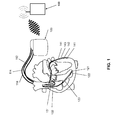
- a cardiac therapy and / or cardiac monitoring device in the form of a three-chamber ICD system is shown.
- This includes a generator 100 (as the cardiac therapy and / or cardiac monitoring device) connected to a plurality of implantable electrode leads 110, 112, and 114.
- a right ventricular (RV) electrode lead 110 is provided which includes a right ventricular (RV) tip electrode 121 and a right ventricular (RV) ring electrode 122 at the distal end.
- a distal shock coil 123 and optionally also a proximal shock coil are attached to this electrode lead 110.
- the counterelectrode here forms the generator housing of the generator 100.
- a right atrial electrode lead 112 has at its distal end a bipolar sensing and pacing pole with a right atrial tip electrode 131 and a right atrial ring electrode 132 for sensing the atrial rhythm and atrial pacing as needed.
- the system also includes a left ventricular CS electrode lead for delivering left ventricular pacing pulses to the CRT via one or more of a total of four left ventricular (CS) stimulation electrode poles 141, 142, 143 and 144.
- CS left ventricular
- a wireless bidirectional telemetry unit is provided in the generator 100.
- FIG. 2 shows the major components of the heart stimulator 100 FIG. 1 , On the left side, the electrical connections for the various electrodes 121, 122, 131 and 132 are shown.
- the shock electrodes 123 are connected to a right ventricular shock pulse generator 50.
- the shock pulse generator 50 is connected to a pacing control unit 54 which drives the shock pulse generator 50 to generate and deliver a defibrillation shock as needed.
- the right ventricular tip electrode connector 121 (RV tip) and right ventricular ring electrode connector 122 (RV ring) are each connected to both a right ventricular pacing unit 56 and a right ventricular sensing unit 58. Both the right ventricular pacing unit 56 and the right ventricular sensing unit 58 are each connected to the pacing control unit 54.
- the right-ventricular stimulation unit 56 is designed to generate a right-ventricular stimulation pulse in response to a control signal of the stimulation control unit 54 and subsequently deliver it via the right-ventricular ring electrode 122 (RV ring) and the right-ventricular tip electrode 121 (RV tip).
- the housing of the generator 100 forms a neutral electrode and the right ventricular pacing unit 56 is connected to the right ventricular ring electrode terminal 122 (RV ring) and the housing as another electrode for delivering a pacing pulse.
- a right ventricular stimulation pulse differs from a defibrillation shock in that the stimulation pulse has a much lower pulse strength so that it does not deliver the full heart tissue (myocardium) of a heartbeat (such as a defibrillation shock) But only the heart muscle cells in the immediate vicinity of the right ventricular tip electrode 121 (RV tip). This excitement then spreads through natural conduction across the entire right ventricle and thus provides for a stimulated contraction of the right ventricle.
- the right ventricular sensing unit 58 is configured to first amplify and filter electrical potential applied to the right ventricular ring electrode terminal 122 (RV ring) and right ventricular tip electrode 121 (RV tip) by an input amplifier. Furthermore, the right ventricular perception unit 58 is designed to evaluate the course of the electrical signals present at its inputs in such a way that the right-ventricular perception unit 58 automatically generates a natural (intrinsic), i. automatic, contraction of the right ventricle detected. This can be done, for example, by comparing the course of the signal applied to the inputs of the right-ventricular perception unit 58 with a threshold value.
- the largest amplitude of the so-called R-wave signal is indicative of a natural contraction of the right ventricle, which can be detected by threshold comparison.
- the right ventricular sensing unit 58 then outputs a corresponding output signal indicative of natural contraction of the right ventricle to the pacing control unit 54.
- the time at which the threshold is exceeded is the detection time for the particular event.
- perception units may be provided. These perception units or perception units are preferably designed to detect signals between the shock electrodes, between the shock electrode 123 and the housing of the generator 100 or between the other shock electrode and the housing of the generator 100.
- connection for the right atrial tip electrode 131 (RA Tip) and the connection for the right atrial ring electrode 132 (RA ring) are both with a right atrial stimulation unit 60 and with a right atrial Perception unit 62, each in turn connected to the stimulation control unit 54.
- the right atrial stimulation unit 60 is designed to generate stimulation pulses whose strength is sufficient to excite the right atrial myocardium.
- the right-atrial stimulation pulses may have a different pulse strength than the right-ventricular stimulation pulses.
- the right-atrial perception unit 62 is designed to detect a so-called P-wave from the course of the differential signal present at its inputs, which characterizes a natural (intrinsic) contraction of the right atrium. If the right atrial sensing unit 62 detects a corresponding P-wave, it generates an output signal and passes it on to the stimulation control unit 54, which identifies a natural contraction of the right atrium.
- left ventricular tip electrode terminal 141 (LV tip) and the left ventricular ring electrode terminals 142, 143, and 144 (for convenience, only one LV ring terminal is shown) are provided with a left ventricular pacing unit 64 and a left ventricular pacing unit Connected left ventricular perception unit 66.
- the left ventricular pacing unit 64 and the left ventricular sensing unit 66 are also connected to the pacing control unit 54. Both work similarly to the previously described stimulation units 56 and 60 and perception units 58 and 62.
- an acceleration sensor 72 is connected to the stimulation control unit 54 and integrated into the housing 42 of the heart stimulator 100.
- the acceleration sensor 72 is designed to detect a movement signal dependent on the physical activity of a patient and to output a corresponding first accelerometer output signal, which indicates the physical activity of the patient, to the stimulation control unit 54. This allows the pacing control unit 54 to adjust the timing of the pacing pulses to the needs of the patient (hemodynamic needs).
- the accelerometer output signal can also be used to determine rest periods, in which preferably a dislocation detection can take place.
- the generator 100 comprises a memory unit 80, which is connected to the stimulation control unit 54 and allows signals generated or evaluated by the stimulation control unit 54 to be stored.
- the memory unit 80 allows control programs for the stimulation control unit 54 to be stored in changeable form.
- the stimulation control unit 54 is connected to an MRT sensor 200.
- the MRI sensor 200 comprises a field recognition unit, as associated with FIG. 4 is explained in more detail and may additionally comprise a magnetic field sensor and / or a gradient field sensor and / or a high-frequency field sensor and / or a position sensor and / or a (Lorentz) vibration sensor and / or a voltage waveform sensor.
- the memory unit 80 is connected to a telemetry unit 84, which allows data stored in the memory unit 80 to be wirelessly transmitted to the external device 160 or to transmit programming commands from the external device 160 to the heart stimulator 100 and stored in the memory unit 80.
- the implantable electronic device allows automatic MRI detection and switching to a safe state during an MRI examination, wherein at least two patient-specific MRI program settings are stored in the implantable electronic device, which are detected as a function of the implant before the MRI examination Patient status will be automatically selected.
- FIG. 3 is a typical sequence of an MRI examination of an ICD patient without inventive device shown.
- An ICD patient 300 is followed up by a cardiologist 310 and the ICD is turned off prior to the scheduled MRI scan.
- the MRI examination is performed by a radiologist 320.
- the patient is again cared for by the cardiologist 330 and the ICD is switched on again.
- the entire time beginning with the MRI scan by a radiologist 320 to to the reconnection of the ICD by the cardiologist 330 is the patient without the protection of the implanted defibrillator and largely without rhythm monitoring.
- this residual residual risk measured by the benefit of the MRI scan, is accepted.
- the illustrated sequence can indeed be changed in such a way that now the MRI setting only becomes effective during the MRI examination and the final follow-up by the cardiologist 330 for the reprogramming can be dispensed with.
- the time of the first follow-up by the cardiologist 310 for determining the MRI program can not take place arbitrarily long before the actual MRI examination by the radiologist 320, since the conditions of the patient change and thus an adaptation of the MRI program becomes necessary ,
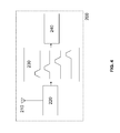
- FIG. 4 a possible block diagram of an MRI sensor 200 of such an electronic implant 100 is shown.
- the MRT sensor 200 includes at least one antenna 210, connected to an antenna matching network / amplifier 220, in turn connected to a tunable, low-power broadband frequency detection unit 230 which cyclically scans the field strengths of the defined ambient frequencies and signals to a control unit 240.
- the control unit 240 compares all of the broadband frequency detection unit 230 received with a field strength above a (predetermined) boundary field strength with previously stored field characteristics, namely in particular previously stored frequency ranges of such ambient frequencies, typically in the environment of the implantable electronic device outside the Environment of an MRI device are present. If this control unit 240 no longer recognizes any of these previously stored ambient frequencies, the control unit 240 signals an MRT environment.
- the broadband frequency detection unit 230 together with the control unit 240 forms a field identification unit.
- Suitable frequencies should be selected from the frequency bands between 30kHz to 30GHz.
Landscapes
- Health & Medical Sciences (AREA)
- Animal Behavior & Ethology (AREA)
- Life Sciences & Earth Sciences (AREA)
- Engineering & Computer Science (AREA)
- Biomedical Technology (AREA)
- General Health & Medical Sciences (AREA)
- Radiology & Medical Imaging (AREA)
- Veterinary Medicine (AREA)
- Public Health (AREA)
- Nuclear Medicine, Radiotherapy & Molecular Imaging (AREA)
- Heart & Thoracic Surgery (AREA)
- Cardiology (AREA)
- Physics & Mathematics (AREA)
- Electromagnetism (AREA)
- Neurology (AREA)
- Neurosurgery (AREA)
- Electrotherapy Devices (AREA)
Abstract
Die Erfindung betrifft ein implantierbares elektronisches Gerät, das mindestens eine elektromagnetische Felderkennungseinheit aufweist, die mit wenigstens einer Antenne verbunden ist. Außerdem ist die Felderkennungseinheit ausgebildet, auf elektromagnetische Felder anzusprechen, die typischerweise in der Umgebung eines Patienten außerhalb der Umgebung eines MRT-Gerätes auftreten und in der Umgebung eines MRT-Gerätes abgeschirmt sind. Darüberhinaus ist die Felderkennungseinheit ausgebildet, die Abwesenheit solcher elektromagnetischer Felder anzuzeigen, die typischerweise in der Umgebung eines Patienten außerhalb der Umgebung eines MRT-Gerätes auftreten und in der Umgebung eines MRT-Gerätes abgeschirmt sind.The invention relates to an implantable electronic device having at least one electromagnetic field detection unit which is connected to at least one antenna. In addition, the field recognition unit is designed to respond to electromagnetic fields that typically occur in the environment of a patient outside the environment of an MRI device and are shielded in the environment of an MRI device. In addition, the field recognition unit is configured to indicate the absence of such electromagnetic fields that typically occur in the environment of a patient outside the environment of an MRI device and are shielded in the environment of an MRI device.
Description
Die Erfindung betrifft einen MRT-Sensor für ein implantierbares elektronisches Gerät, der in der Lage ist zu erfassen, wenn das implantierbare elektronische Gerät innerhalb oder in unmittelbarer Umgebung eines MRT-Gerätes (Magnetresonanztomographen) betrieben wird. Außerdem betrifft die Erfindung ein MRT-taugliches implantierbares elektronisches Gerät, insbesondere ein implantierbares Herz-Therapie- und/oder Herz-Monitoring-Gerät, beispielsweise einen Herzschrittmacher oder Kardioverter/Defibrillator, mit einem MRT-Sensor.The invention relates to an MRI sensor for an implantable electronic device, which is able to detect when the implantable electronic device is operated within or in the immediate vicinity of an MRI device (magnetic resonance tomograph). Moreover, the invention relates to an MRI-compatible implantable electronic device, in particular an implantable cardiac therapy and / or cardiac monitoring device, such as a pacemaker or cardioverter / defibrillator, with an MRI sensor.
Implantierbare Herz-Therapie- und/oder Herz-Monitoring-Geräte, z. B. Herzstimulatoren in Form von Herzschrittmachern oder Cardiovertern/Defibrillatoren, sind grundsätzlich bekannt. Solche Herzstimulatoren sind in der Regel an Elektrodenleitungen angeschlossen, die in einer Kammer eines Herzens oder in deren unmittelbarer Nähe Stimulations- und optional zusätzliche Defibrillationselektroden besitzen. Über eine Stimulationselektrode - genauer: einen oder mehrere Stimulationselektrodenpole - kann ein Herzschrittmacher einen elektrischen Stimulationsimpuls an das Muskelgewebe einer Herzkammer abgeben, um so eine stimulierte Kontraktion der Herzkammer hervorzurufen, sofern der Stimulationsimpuls eine ausreichende Intensität besitzt und das Herzmuskelgewebe (Myokard) sich nicht gerade in einer refraktären Phase befindet. Eine derartig stimulierte Kontraktion einer Herzkammer wird im Rahmen dieser Beschreibung als stimuliertes Ereignis bezeichnet, ein Stimulationsimpuls, der eine ausreichende Intensität besitzt, eine stimulierte Kontraktion einer Herzkammer hervorzurufen, wird als "überschwellig" bezeichnet. Kommt es zu einer natürlichen Kontraktion der Herzkammer, wird dies im Rahmen dieser Beschreibung als Eigenaktion oder als natürliches oder intrinsisches Ereignis bezeichnet. Eine Kontraktion, beispielsweise des rechten Atriums eines Herzens, wird als atriales Ereignis bezeichnet, welches beispielsweise ein natürliches atriales Ereignis sein kann, oder - im Falle eines atrialen Herzschrittmachers - auch ein stimuliertes atriales Ereignis. Im gleichen Sinne können natürliche (intrinsische) und stimulierte linksventrikuläre und rechtsventrikuläre Ereignisse unterschieden werden.Implantable cardiac therapy and / or cardiac monitoring devices, e.g. As cardiac stimulators in the form of cardiac pacemakers or cardioverters / defibrillators are known in principle. Such cardiac stimulators are typically connected to electrode leads that have pacing and, optionally, additional defibrillation electrodes in a chamber of a heart or in its immediate vicinity. Via a stimulation electrode - more precisely one or more stimulation electrode poles - a pacemaker can deliver an electrical stimulation pulse to the muscle tissue of a heart chamber so as to induce a stimulated contraction of the ventricle, provided that the stimulation pulse has sufficient intensity and the myocardial tissue (myocardium) is not in a refractory phase. Such a stimulated contraction of a heart chamber is referred to in this specification as a stimulated event, a stimulation pulse having a sufficient intensity to cause a stimulated contraction of a heart chamber is referred to as "suprathreshold". If there is a natural contraction of the heart chamber, this is referred to in the context of this description as a private action or as a natural or intrinsic event. A contraction, for example of the right atrium of a heart, is referred to as an atrial event, which, for example, is a natural atrial Event, or, in the case of an atrial pacemaker, also a stimulated atrial event. In the same way, natural (intrinsic) and stimulated left ventricular and right ventricular events can be distinguished.
Eine lokale Erregung des Myokards breitet sich vom Erregungsort ausgehend per Reizleitung im Myokard aus und führt zu einer Depolarisation der Muskelzellen und damit zu einer Kontraktion des Myokards. Nach kurzer Zeit kommt es zu einer Repolarisation der Muskelzellen und damit zu einer Entspannung des Myokards. Während der Phase der Depolarisation sind die Herzmuskelzellen für eine Erregung unempfindlich, d.h. refraktär. Diese Zeit wird als Refraktärzeit bezeichnet. Die mit der Depolarisation und Repolarisation einhergehenden elektrischen Potenziale können wahrgenommen und deren zeitlicher Verlauf - als Elektrokardiogramm bezeichnet - ausgewertet werden.A local arousal of the myocardium spreads from the excitation site via stimulation in the myocardium and leads to a depolarization of the muscle cells and thus to a contraction of the myocardium. After a short time a repolarization of the muscle cells occurs and thus a relaxation of the myocardium. During the phase of depolarization, the myocardial cells are insensitive to arousal, i. refractory. This time is called the refractory period. The electrical potentials associated with depolarization and repolarization can be perceived and their time course - referred to as the electrocardiogram - evaluated.
In einem Elektrokardiogramm sind mit einer Kontraktion des Ventrikels einhergehende, eine Depolarisation der Herzmuskelzellen widerspiegelnde Aktionspotenziale als sogenannte Q-Zacke zu erkennen, während sich die mit der Entspannung des Myokards einhergehende Repolarisierung der Herzmuskelzellen in einer sogenannten T-Welle widerspiegelt.In an electrocardiogram, action potentials associated with a contraction of the ventricle and reflecting a depolarization of the heart muscle cells can be recognized as a so-called Q-wave, while the repolarization of the heart muscle cells associated with the relaxation of the myocardium is reflected in a so-called T-wave.
Beim gesunden Menschen wird der jeweilige Herzrhythmus durch den vom autonomen Nervensystem gesteuerten Sinusknoten bestimmt. Dieser erregt per Reizleitung das rechte Atrium eines menschlichen Herzens und weiter über den AV-Knoten den (rechten) Ventrikel des Herzens. Ein vom Sinusknoten ausgehender natürlicher Herzrhythmus wird daher auch als Sinusrhythmus bezeichnet und führt zu jeweils natürlichen Kontraktionen der jeweiligen Herzkammer, die als natürliche (intrinsische) Ereignisse erfasst werden können.In healthy people, the respective heart rhythm is determined by the sinus node controlled by the autonomic nervous system. This stimulates the right atrium of a human heart by stimulation, and continues via the AV node to the (right) ventricle of the heart. A natural heart rhythm emanating from the sinus node is therefore also called sinus rhythm and leads to natural contractions of the respective heart chamber, which can be detected as natural (intrinsic) events.
Das Erfassen solcher natürlicher (intrinsischer) Ereignisse erfolgt durch Ableiten der elektrischen Potenziale des Myokards der jeweiligen Herzkammer mit Hilfe von Wahrnehmungselektroden, die Teil einer entsprechenden Elektrodenleitung sind. Dabei können die Wahrnehmungselektrodenpole gleichzeitig die Stimulationselektrodenpole sein und abwechselnd als Stimulations- und als Wahrnehmungselektrodenpol verwendet werden. Typischerweise ist für das Sensing - d.h. die Wahrnehmung intrinsischer Ereignisse - ein Wahrnehmungselektrodenpolpaar vorgesehen, das von zwei benachbarten Elektrodenpolen, nämlich einer Spitzenelektrode (Tip-Elektrode) und einer Ring-Elektrode, gebildet ist, von denen die Spitzenelektrode auch als Stimulationselektrodenpol dient. Auf diese Weise erfolgt eine bipolare Ableitung eines intrakardialen Elektrokardiogramms (IEGM). Dabei erfolgt die Wahrnehmung intrinsischer Ereignisse und die Stimulation im Ventrikel mit Hilfe einer ventrikulären Elektrodenleitung und die Stimulation und die Wahrnehmung intrinsischer Ereignisse im Atrium (im rechten Atrium) mit einer atrialen Elektrodenleitung, die separat an den jeweiligen Herzstimulator angeschlossen sind. Zusätzlich kann auch eine linksventrikuläre Elektrodenleitung vorgesehen sein, die typischerweise über den Coronarsinus und eine von diesem abzweigende Lateralvene in die Nähe des linken Ventrikels ragt und dort eine kleinflächige Stimulations- und/oder Wahrnehmungselektrode aufweisen kann.The detection of such natural (intrinsic) events is carried out by deriving the electrical potentials of the myocardium of the respective heart chamber by means of sensing electrodes, which are part of a corresponding electrode line. In this case, the sense electrode poles can simultaneously be the stimulation electrode poles and used alternately as a stimulation pole and as a sense electrode pole become. Typically, for the sensing - ie the perception of intrinsic events - a sense electrode pole pair is provided, which is formed by two adjacent electrode poles, namely a tip electrode (tip electrode) and a ring electrode, of which the tip electrode also serves as stimulation electrode pole. In this way, a bipolar derivative of an intracardiac electrocardiogram (IEGM) takes place. The perception of intrinsic events and the stimulation in the ventricle by means of a ventricular lead and the stimulation and the perception of intrinsic events in the atrium (in the right atrium) with an atrial electrode lead, which are connected separately to the respective heart stimulator. In addition, a left ventricular electrode lead may also be provided, which typically projects beyond the coronary sinus and a lateral vein branching off from it into the vicinity of the left ventricle and may have a small-area stimulation and / or sensing electrode there.
Um den unterschiedlichen Bedürfnissen verschiedener Patienten gerecht werden zu können, können implantierbare Herzstimulatoren in verschiedenen Betriebsmodi betrieben werden. Die verschiedenen Stimulations- und Wahrnehmungsmodi werden in der Regel einheitlich mit einem Drei-Buchstaben-Code bezeichnet, von denen der erste Buchstabe den Stimulationsort bezeichnet (V = Ventrikel, A = Atrium, D = Ventrikel und Atrium), der zweite Buchstabe den Ort der Wahrnehmung bezeichnet (V = Ventrikel, A = Atrium, D = Ventrikel und Atrium) und der dritte Buchstabe die Betriebsart (I = Inhibiert, T = Getriggert, D = sowohl Inhibiert als auch Getriggert). Insbesondere für Zwei-Kammer-Herzschrittmacher im DDD-Modus ist es auch bekannt, eine ventrikuläre Stimulation synchron zu einer möglichst natürlichen atrialen Herzrate vorzunehmen. Falls im Atrium keine gesunde, natürliche Herzrate wahrzunehmen ist, beispielsweise im Falle einer atrialen Tachykardie oder einer atrialen Fibrillation, weisen grundsätzlich atriumsynchrone Herzschrittmacher häufig ein Modeswitching von einer atriumsynchronen ventrikulären Stimulation zu einer atriumasynchronen Stimulation im VVI-Modus auf, falls eine wahrgenommene atriale Rate außerhalb zulässiger Grenzen liegt. Weiterhin ist es bekannt, ventrikuläre Tachykardien im Rahmen einer Kardioversionstherapie durch Stimulation mit einer Stimulationsrate, die über der Tachykardierate liegt, zu behandeln.In order to meet the different needs of different patients, implantable cardiac stimulators can be operated in different modes of operation. The various modes of pacing and sensing are typically uniformly denoted by a three-letter code, the first letter designating the location of stimulation (V = ventricle, A = atrium, D = ventricle and atrium), the second letter is the location of the stimulus Perception is designated (V = ventricle, A = atrium, D = ventricle and atrium) and the third letter is the mode (I = inhibited, T = triggered, D = both inhibited and triggered). In particular, for two-chamber pacemakers in DDD mode, it is also known to perform a ventricular stimulation synchronously to a natural atrial heart rate as possible. In the absence of a healthy, natural heart rate in the atrium, for example in the case of atrial tachycardia or atrial fibrillation, atrial pacemakers generally have a mode switching from atrial-synchronous ventricular pacing to atrial-asynchronous pacing in VVI mode if a perceived atrial rate is outside permissible limits. Furthermore, it is known to treat ventricular tachycardias as part of a cardioversion therapy by stimulation with a stimulation rate that is above the tachycardia rate.
Die Stimulationsmodi können durch entsprechende Steuerprogramme, die z. B. erfasste Ereignisse verarbeiten oder ignorieren, oder durch Steuerparameter eingestellt werden. So kann beispielsweise durch einen Steuerparameter die Erfassung von Ereignissen im Atrium und/oder Ventrikel aktiviert oder deaktiviert werden.The stimulation modes can be controlled by appropriate control programs, the z. For example, process or ignore captured events, or set by control parameters. For example, a control parameter can be used to activate or deactivate the detection of events in the atrium and / or ventricle.
In Bezug auf die hierin verwendeten Bezeichnungen sei darauf hingewiesen, dass im Rahmen dieses Textes mit den Begriffen Stimulations- oder Wahrnehmungselektrode ein jeweiliger Elektrodenpol an einer Elektrodenleitung gemeint ist, also derjenige Teil einer Elektrodenleitung, über den Stimulationsimpulse abgegeben oder elektrische Potenziale aufgenommen werden. Es sei auch darauf hingewiesen, dass es auch üblich ist, mit "Stimulationselektrode" eine der Stimulation dienende Elektrodenleitung zu bezeichnen.With respect to the terms used herein, it is to be understood that in the context of this text the term stimulation or sensing electrode means a respective electrode pole on an electrode lead, that is, that part of an electrode lead via which stimulation pulses are delivered or electrical potentials are picked up. It should also be noted that it is also common to refer to a stimulation electrode serving as a stimulation electrode lead.
Die Wahrnehmungselektrodenpole sind im Betrieb des Herzstimulators mit entsprechenden Wahrnehmungseinheiten verbunden, die ausgebildet sind, ein jeweiliges über einen Wahrnehmungselektrodenpol (bzw. ein Wahrnehmungselektrodenpolpaar) aufgenommenes Elektrokardiogramm auszuwerten und insbesondere intrinsische atriale bzw. ventrikuläre Ereignisse zu detektieren, d.h. natürliche atriale oder ventrikuläre Kontraktionen. Dies geschieht beispielsweise durch einen Schwellwertvergleich, d.h. ein intrinsisches Ereignis wird detektiert, wenn ein jeweiliges intrakardiales Elektrokardiogramm einen als geeignet vorgegebenen Schwellwert überschreitet.The sensing electrode poles, in operation of the cardiac stimulator, are connected to respective sensing units configured to evaluate a respective electrocardiogram acquired via a sensing electrode pole (or sense electrode pole pair) and, in particular, to detect intrinsic atrial or ventricular events, i. natural atrial or ventricular contractions. This is done, for example, by a threshold comparison, i. An intrinsic event is detected when a respective intracardiac electrocardiogram exceeds a threshold value that is considered appropriate.
Aus der Frequenz, mit der atriale bzw. ventrikuläre Ereignisse aufeinander folgen, kann die jeweilige intrinsische atriale Herzrate (atriale Frequenz) bzw. ventrikuläre Herzrate (Ventrikelfrequenz) abgeleitet und somit beispielsweise Tachykardien detektiert werden.From the frequency with which atrial or ventricular events follow one another, the respective intrinsic atrial heart rate (atrial frequency) or ventricular heart rate (ventricular frequency) can be derived and thus, for example, tachycardias can be detected.
Das Erfassen natürlicher Ereignisse dient bei bekannten Demand-Schrittmachern außerdem der Unterdrückung (Inhibierung) der Abgabe von Stimulationsimpulsen an eine entsprechende Herzkammer, falls das natürliche Ereignis in einem Zeitfenster vor der geplanten Abgabe eines Stimulationsimpulses an diese Herzkammer erfasst wird. Bei ratenadaptiven Herzschrittmachern wird der Zeitpunkt der Abgabe eines jeweiligen Stimulationsimpulses in Abhängigkeit einer jeweiligen Stimulationsrate geplant, die dem physiologischen Bedarf eines Patienten entsprechen soll, also bei größerer Anstrengung beispielsweise höher ist. Hierzu kann ein Herzstimulator mit einem oder mehreren Aktivitätssensoren ausgestattet sein, der beispielsweise ein CLS-Sensor (CLS: Closed Loop Stimulation) sein kann.The detection of natural events in known demand pacemakers also serves to suppress (inhibit) the delivery of pacing pulses to a corresponding ventricle if the natural event is detected in a time window prior to the scheduled delivery of a pacing pulse to that ventricle. In rate-adaptive cardiac pacemakers, the timing of delivery of a respective stimulation pulse is scheduled in response to a respective stimulation rate that is intended to meet a patient's physiological needs, that is, greater effort for example, higher. For this purpose, a heart stimulator may be equipped with one or more activity sensors, which may be, for example, a CLS sensor (CLS: Closed Loop Stimulation).
Problematisch ist, dass solche implantierbaren elektrischen medizinischen Geräte wie Herzstimulatoren durch starke elektromagnetische Felder oder Magnetfelder, wie sie zum Beispiel in einem Magnetresonanztomographen, (MRT-Gerät) auftreten, in ihrer Funktion stark beeinträchtigt werden können. Daher sind viele Träger von aktiven implantierbaren medizinischen Geräten (im Folgenden auch Implantat oder IMD genannt) für MRT-Untersuchungen kontraindiziert, obwohl MRT-Untersuchungen einen immer höheren Stellenwert in der diagnostischen Medizin erhalten.The problem is that such implantable electrical medical devices such as cardiac stimulators by strong electromagnetic fields or magnetic fields, such as those that occur in a magnetic resonance imaging (MRI), for example, can be severely impaired in their function. Therefore, many wearers of active implantable medical devices (hereafter referred to as implant or IMD) are contraindicated for MRI scans, although MR scans are gaining more and more importance in diagnostic medicine.
Um Trägern von aktiven implantierbaren medizinischen Geräten MRT-Untersuchungen dennoch zu ermöglichen sind verschiedene Ansätze, die sich entweder auf die Durchführung der MRT-Untersuchung oder auf das implantierbare medizinische Gerät beziehen, bekannt.However, to enable MRI scanners for active implantable medical device wearers, various approaches relating to either performing the MRI scan or the implantable medical device are known.
Unter anderem sind Technologien zur Erkennung von Magnetfeldern bekannt, die auf herkömmlichen Verfahren zur Magnetfelddetektion beruhen. So beschreibt die
Daneben sind auch andere MRT-Sensoren bekannt, insbesondere Magnetfeldsensoren, Gradientenfeldsensoren, Hochfrequenz-Feldsensoren, Lagesensoren, Geräusch- oder (Lorentz-)Vibrationssensoren oder Spannungsverlaufssensoren, die charakteristische Spannungsverläufe überwachen.In addition, other MRT sensors are known, in particular magnetic field sensors, gradient field sensors, high-frequency field sensors, position sensors, noise or (Lorentz) vibration sensors or voltage waveform sensors which monitor characteristic voltage profiles.
Auch ist es bekannt, dass beispielsweise ein implantierbarer Kardioverter/Defibrillator (ICD) vor einer MRT-Untersuchung durch einen Kardiologen in einen Betriebsmodus versetzt wird, der durch die im MRT herrschenden Magnetfelder nicht beeinträchtigt wird. Nach der MRT-Untersuchung durch einen Radiologen muss ein Kardiologe den ICD wieder in einen Betriebsmodus versetzen, der den Bedürfnissen des Patienten entspricht. Der Erfindung liegt die Aufgabe zugrunde eine Ergänzung oder eine Alternative zu bekannten MRT-Sensoren zu schaffen. Ein weiterer Aspekt ist ein alternatives oder ergänztes implantierbares elektronisches Gerät mit einem MRT-Sensor.It is also known that, for example, an implantable cardioverter / defibrillator (ICD) is placed in an operating mode by an cardiologist prior to an MRI scan, which is not affected by the MRI magnetic fields. Following a radiologist's MRI, a cardiologist must return the device to an operating mode that meets the needs of the patient. The invention has for its object to provide a supplement or an alternative to known MRT sensors. Another aspect is an alternative or supplemented implantable electronic device with an MRI sensor.
Erfindungsgemäß wird diese Aufgabe durch ein implantierbares elektronisches Gerät gelöst, das mindestens eine elektromagnetische Felderkennungseinheit aufweist, die mit wenigstens einer Antenne verbunden ist. Außerdem ist die Felderkennungseinheit ausgebildet, auf elektromagnetische Felder anzusprechen, die typischerweise in der Umgebung eines Patienten außerhalb der Umgebung eines MRT-Gerätes auftreten und in der Umgebung eines MRT-Gerätes abgeschirmt sind. Darüberhinaus ist die Felderkennungseinheit ausgebildet, die Abwesenheit solcher elektromagnetischer Felder anzuzeigen, die typischerweise in der Umgebung eines Patienten außerhalb der Umgebung eines MRT-Gerätes auftreten und in der Umgebung eines MRT-Gerätes abgeschirmt sind.According to the invention this object is achieved by an implantable electronic device having at least one electromagnetic field detection unit which is connected to at least one antenna. In addition, the field recognition unit is designed to respond to electromagnetic fields that typically occur in the environment of a patient outside the environment of an MRI device and are shielded in the environment of an MRI device. In addition, the field recognition unit is configured to indicate the absence of such electromagnetic fields that typically occur in the environment of a patient outside the environment of an MRI device and are shielded in the environment of an MRI device.
Die Felderkennungseinheit kann wenigstens einen auf solche elektromagnetische Felder, wie sie typischerweise in der Umgebung eines Patienten außerhalb der Umgebung eines MRT-Gerätes auftreten und in der Umgebung eines MRT-Gerätes abgeschirmt sind, abgestimmten Empfänger enthalten. Vorzugsweise enthält die Felderkennungseinheit mehrere solche Empfänger. Wenn keiner dieser Empfänger in seinem jeweiligen Empfangsbereich eine Feldstärke oberhalb einer vorgegebenen Grenzfeldstärke anzeigt, signalisiert eine mit dem Empfänger oder den Empfängern verbundene Steuereinheit die Abwesenheit solcher elektromagnetischer Felder, die typischerweise in der Umgebung eines Patienten außerhalb der Umgebung eines MRT-Gerätes auftreten und in der Umgebung eines MRT-Gerätes abgeschirmt sind.The field recognition unit may include at least one receiver tuned to such electromagnetic fields as typically occur in the environment of a patient outside the environment of an MRI apparatus and shielded in the vicinity of an MRI apparatus. The field identification unit preferably contains a plurality of such receivers. If none of these receivers indicate a field strength in excess of a given limit field strength in their respective receiving area, a control unit connected to the receiver or receivers signals the absence of such electromagnetic fields that typically occur in the environment of a patient outside the environment of an MRI apparatus and in the The environment of an MRI device are shielded.
Alternativ kann die Felderkennungseinheit auch einen durchstimmbaren Empfänger als Breitbandfrequenzerkennungseinheit zum Scannen eines breiteren Frequenzbereichs aufweisen und mit einem Feld-Charakteristika-Speicher verbunden sein oder einen solchen aufweisen. Der Feld-Charakteristika-Speicher enthält charakteristische Merkmale von elektromagnetischen Feldern, die nur außerhalb der Umgebung eines MRT-Gerätes auftreten und in der Umgebung eines MRT-Gerätes abgeschirmt sind. Solche charakteristischen Merkmale können beispielsweise Frequenzen oder Frequenzbereiche elektromagnetischer Felder sein.Alternatively, the field recognition unit may also have a tunable receiver as a wideband frequency detection unit for scanning a wider frequency range and be connected to or have a field characteristic memory. The field characteristics memory contains characteristic features of electromagnetic fields which occur only outside the environment of an MRI apparatus and are shielded in the environment of an MRI apparatus. Such characteristic features may be, for example, frequencies or frequency ranges of electromagnetic fields.
Die Felderkennungseinheit ist so ausgelegt, dass diese die Abwesenheit eines oder mehrerer normalerweise in der Patientenumgebung vorhandenen elektromagnetischen Felder erkennt und immer dann die MRI-Umgebung anzeigt, wenn alle Felder "verschwunden" sind.The field recognition unit is designed to detect the absence of one or more electromagnetic fields normally present in the patient environment and to display the MRI environment whenever all fields have "disappeared".
Ein erfindungsgemäßer MRT-Sensor erlaubt es durch automatisches Erkennen der Umgebung eines MRT-Gerätes, die Tauglichkeit eines aktiven implantierbaren medizinischen Gerätes auch unter dem Einfluss von Magnetfeldern, wie sie für einen Magnetresonanztomographen (MRT) typisch sind, zu verbessern.An MRI sensor according to the invention makes it possible, by automatically detecting the surroundings of an MRI apparatus, to improve the fitness of an active implantable medical device even under the influence of magnetic fields typical of a magnetic resonance tomograph (MRI).
Vorzugsweise ist der MRT-Sensor Teil eines elektronischen implantierbaren Gerätes in Form eines Herzstimulators, der eine Stimulationssteuereinheit und eine Speichereinheit aufweist. In der Speichereinheit ist Programminformation zu Steuerprogrammen und/oder Steuerparametern gespeichert, die die Funktion der Stimulationssteuereinheit steuern. Außerdem ist die Stimulationssteuereinheit ausgebildet, dann, wenn die Felderkennungseinheit die Abwesenheit solcher elektromagnetischer Felder anzeigt, die typischerweise in der Umgebung eines Patienten außerhalb der Umgebung eines MRT-Gerätes auftreten und in der Umgebung eines MRT-Gerätes abgeschirmt sind, solch ein Steuerprogramm oder solche Steuerparameter auszuwählen, die einen sicheren Betrieb des implantierbaren elektronischen Gerätes in der Umgebung eines MRT-Gerätes erlauben. Die auszuwählenden Steuerprogramme oder Steuerparameter sind beispielsweise solche, die den Wahrnehmungs- und/oder Stimulationsmodus auf V00 oder A00 festlegen, also die Wahrnehmung ausschalten.Preferably, the MRI sensor is part of an electronic implantable device in the form of a heart stimulator, which has a stimulation control unit and a memory unit. The memory unit stores program information on control programs and / or control parameters which control the function of the stimulation control unit. In addition, if the field recognition unit indicates the absence of such electromagnetic fields that typically occur in the environment of a patient outside the environment of an MRI device and are shielded in the vicinity of an MRI device, the stimulation control unit is such a control program or control parameters to allow safe operation of the implantable electronic device in the environment of an MRI device. The control programs or control parameters to be selected are, for example, those which set the perception and / or pacing mode to V00 or A00, ie switch off the perception.
Weiterhin ist die Stimulationssteuereinheit vorzugsweise ausgebildet das ausgewählte Steuerprogramm oder die ausgewählten Steuerparameter solange beizubehalten, solange die Felderkennungseinheit die Abwesenheit solcher elektromagnetischer Felder anzeigt, die typischerweise in der Umgebung eines Patienten außerhalb der Umgebung eines MRT-Gerätes auftreten und in der Umgebung eines MRT-Gerätes abgeschirmt sind. Steuerprogramme oder Steuerparameter bestimmen die Funktionsweise, insbesondere den jeweiligen Betriebsmodus des implantierbaren elektronischen Gerätes, der typischerweise von der Stimulationssteuereinheit gesteuert wird. In diesem Sinne beeinflussen in der Speichereinheit gespeicherte Steuerprogramme oder Steuerparameter die Arbeitsweise der Stimulationssteuereinheit. Im vorliegenden Fall steuert die Stimulationssteuereinheit nicht nur den Betrieb des implantierbaren elektronischen Gerätes hinsichtlich beispielsweise einer Therapieabgabe wie der Herzstimulation, sondern die Stimulationssteuereinheit wählt auch ein jeweils anzuwendendes Steuerprogramm oder anzuwendende Steuerparameter aus, die ihrerseits dann wieder z. B. die Therapieabgabe definieren.Furthermore, the stimulation control unit is preferably designed to maintain the selected control program or parameters as long as the field recognition unit indicates the absence of electromagnetic fields typically occurring in the environment of a patient outside the environment of an MRI device and shielded in the environment of an MRI device are. Control programs or control parameters determine the mode of operation, in particular the respective operating mode of the implantable electronic device, which is typically controlled by the stimulation control unit. In this sense, control programs or control parameters stored in the memory unit affect the operation of the pacing control unit. In the present case, the stimulation control unit controls not only the operation of the implantable electronic device with respect to, for example, a therapy delivery such as cardiac stimulation, but the stimulation control unit also selects a respective applicable control program or applicable control parameters, which in turn then z. B. define the therapy delivery.
Die Erfindung ermöglicht den sicheren Betrieb eines elektronischen Implantates in einem MRT, ohne dass unmittelbar vor der Untersuchung eine Umprogrammierung bzw. Anpassung des MRT-Programmes stattfinden muss.The invention enables the safe operation of an electronic implant in an MRI, without having to re-program or adapt the MRI program immediately before the examination.
In einer bevorzugten Ausführungsform ist das elektronische implantierbare Gerät ein implantierbarer Pulsgenerator (IPG) und/oder ein implantierbarer Cardioverter/Defibrillator (ICD) und/oder ein Herzstimulator für eine kardiale Resynchronisationstherapie (CRT) oder ein Neurostimulator. Besonders bevorzugt ist das elektronische implantierbare Gerät ein Herz-Therapie- und/oder Herz-Monitoring-Gerät, insbesondere ein implantierbarer, beispielsweise biventrikulärer Herzschrittmacher und/oder Kardioverter/Defibrillator. Mit einem biventrikulären Herzschrittmacher kann insbesondere eine kardiale Resynchronisations-Therapie (CRT) durchgeführt werden.In a preferred embodiment, the electronic implantable device is an implantable pulse generator (IPG) and / or an implantable cardioverter / defibrillator (ICD) and / or cardiac resynchronization therapy (CRT) heart stimulator or neurostimulator. The electronic implantable device is particularly preferably a cardiac therapy and / or cardiac monitoring device, in particular an implantable, for example biventricular pacemaker and / or cardioverter / defibrillator. In particular, a cardiac resynchronization therapy (CRT) can be carried out with a biventricular pacemaker.
Vorzugsweise enthält die Speichereinheit ein von der Steuereinheit wählbares Steuerprogramm, das so konfiguriert ist, dass dieses Steuerprogramm ein Auslösen von Stimulationsimpulsen unterbindet. Die Speichereinheit beinhaltet somit mindestens ein Programm, das einen Betriebsmodus bewirkt, der ohne Stimulation ist.Preferably, the memory unit includes a control program selectable by the control unit configured to inhibit stimulation pulses from being triggered by this control program. The memory unit thus includes at least one program that effects an operating mode that is without stimulation.
Falls das implantierbare elektronische Gerät ein Herzschrittmacher ist, kann die Speichereinheit alternativ auch ein von der Steuereinheit wählbares Steuerprogramm oder wählbare Steuerparameter enthalten, das so konfiguriert ist bzw. die so konfiguriert sind, dass es die Steuereinheit veranlasst, eine asynchrone Stimulation in einem asynchronen Stimulationsmodus wie V00 oder D00 zu bewirken. Gemäß dem weiter vorne beschriebenen Drei-Buchstaben-Code kommen diese Stimulationsmodi ohne Wahrnehmung intrinsischer Ereignisse aus, sodass auch keine Inhibierung oder Triggerung von Stimulationsimpulsen durch erfasste intrinsische Ereignisse erfolgt. Derartige Stimulationsmodi tragen dem Umstand Rechnung, dass ein Herzstimulator infolge wechselnder magnetischer oder elektromagnetischer Felder durch diese Felder induzierte Signale fälschlicherweise als intrinsische Ereignisse erfassen könnte. In einem reinen Stimulationsmodus, der ohne das Erfassen intrinsischer Ereignisse auskommt, besteht dieses Problem nicht.Alternatively, if the implantable electronic device is a pacemaker, the memory device may also include a control program selectable by the control unit or selectable control parameters configured or configured such that causing the control unit to cause asynchronous pacing in an asynchronous pacing mode such as V00 or D00. According to the three-letter code described earlier, these pacing modes do not require the sensing of intrinsic events, so there is no inhibition or triggering of pacing pulses by sensed intrinsic events. Such stimulation modes take into account the fact that as a result of changing magnetic or electromagnetic fields, a heart stimulator could erroneously detect signals induced by these fields as intrinsic events. In a pure stimulation mode that does not require the detection of intrinsic events, this problem does not exist.
Falls das implantierbare elektronische Gerät ein Herzschrittmacher ist, ist es weiter bevorzugt, wenn in der Speichereinheit ein Steuerprogramm abgelegt ist, das von der Steuereinheit gewählt werden kann und das so konfiguriert ist, dass es eine asynchrone Stimulation in einem asynchronen Stimulationsmodus wie VOO oder DOO bewirkt.If the implantable electronic device is a pacemaker, it is further preferred if the memory unit stores a control program that can be selected by the control unit and that is configured to cause asynchronous pacing in an asynchronous pacing mode such as VOO or DOO ,
Jeweils auszuwählende Steuerprogramme oder Steuerparameter sind vorzugsweise grundsätzlich so gewählt, dass sie einen grundsätzlich sicheren Betrieb des implantierbaren elektronischen Gerätes in einem Magnetresonanztomographen gewährleisten, beispielsweise das Deaktivieren der Schockabgabe in einem ICD.Control programs or control parameters to be selected in each case are preferably selected so as to ensure fundamentally safe operation of the implantable electronic device in a magnetic resonance tomograph, for example deactivating the shock delivery in an ICD.
Vorzugsweise weist der MRT-Sensor zusätzlich einen Magnetfeldsensor und/oder einen Gradientenfeldsensor und/oder einen Hochfrequenz-Feldsensor und/oder einen Lagesensor und/oder einen (Lorenz-)Vibrationssensor und/oder einen Spannungsverlaufssensor auf, der charakteristische Spannungsverläufe beispielsweise in den Elektrodenleitungen überwacht.Preferably, the MRT sensor additionally has a magnetic field sensor and / or a gradient field sensor and / or a high-frequency field sensor and / or a position sensor and / or a (Lorenz) vibration sensor and / or a voltage profile sensor which monitors characteristic voltage profiles, for example in the electrode lines ,
Die Erfindung soll nun anhand von Ausführungsbeispielen mit Bezug auf die Figuren näher erläutert werden. Die Figuren zeigen in
- Figur 1:
- Ein System mit einem Herz-Therapie- und/oder Herz-Monitoring-Gerät als implantierbarem elektronischen Gerät in Form eines Dreikammer-ICD-Systems;
- Figur 2:
- die Hauptbestandteile des Herz-Therapie- und/oder Herz-Monitoring-Gerätes aus
Figur 1 ; - Figur 3:
- einen typischen Ablauf einer MRT-Untersuchung eines ICD-Patienten mit einem implantierbaren elektronischen Gerät ohne MRT-Sensor; und
- Figur 4:
- ein mögliches Blockschaltbild eines erfindungsgemäßen MRT-Sensors.
- FIG. 1:
- A system comprising a cardiac therapy and / or cardiac monitoring device as an implantable electronic device in the form of a three-chamber ICD system;
- FIG. 2:
- the main components of the heart therapy and / or cardiac monitoring device
FIG. 1 ; - FIG. 3:
- a typical course of an MRI examination of an ICD patient with an implantable electronic device without an MRI sensor; and
- FIG. 4:
- a possible block diagram of an MRI sensor according to the invention.
In
Eine rechtsatriale Elektrodenleitung 112 weist an ihrem distalen Ende einen bipolaren Wahrnehmungs- und Stimulationspol mit einer rechtsatrialen Tip-Elektrode 131 und einer rechtsatrialen Ring-Elektrode 132 auf und dient der Wahrnehmung des atrialen Rhythmus und bei Bedarf der atrialen Stimulation.A right
Außerdem umfasst das System auch eine linksventrikuläre CS-Elektrodenleitung zur Abgabe von linksventrikulären Stimulationsimpulsen zur CRT über einen oder mehrere von insgesamt vier linksventrikulären (CS-) Stimulationselektrodenpolen 141, 142, 143 und 144.In addition, the system also includes a left ventricular CS electrode lead for delivering left ventricular pacing pulses to the CRT via one or more of a total of four left ventricular (CS)
Für eine Kommunikation mit externen Programmier- und Steuer- und Datenübertragungsgeräten 160 ist in dem Generator 100 eine drahtlose, bidirektionale Telemetrieeinheit vorgesehen.For communication with external programming and control and
Der Anschluss für die rechtsventrikuläre Tip-Elektrode 121 (RV Tip) sowie der Anschluss für die rechtsventrikuläre Ring-Elektrode 122 (RV Ring) ist jeweils sowohl mit einer rechtsventrikulären Stimulationseinheit 56 als auch mit einer rechtsventrikulären Wahrnehmungseinheit 58 verbunden. Sowohl die rechtsventrikuläre Stimulationseinheit 56 als auch die rechtsventrikuläre Wahrnehmungseinheit 58 sind jeweils mit der Stimulationssteuereinheit 54 verbunden.The right ventricular tip electrode connector 121 (RV tip) and right ventricular ring electrode connector 122 (RV ring) are each connected to both a right
Die rechtsventrikuläre Stimulationseinheit 56 ist dazu ausgebildet, auf ein Ansteuersignal der Stimulationssteuereinheit 54 hin einen rechtsventrikulären Stimulationsimpuls zu erzeugen und im Anschluss über die rechtsventrikuläre Ring-Elektrode 122 (RV Ring) und die rechtsventrikuläre Tip-Elektrode 121 (RV Tip) abzugeben. Alternativ ist es auch möglich, dass das Gehäuse des Generators 100 eine neutrale Elektrode bildet und die rechtsventrikuläre Stimulationseinheit 56 mit dem Anschluss für die rechtsventrikuläre Ring-Elektrode 122 (RV Ring) und dem Gehäuse als andere Elektrode zur Abgabe eines Stimulationsimpulses verbunden ist. Ein rechtsventrikulärer Stimulationsimpuls unterscheidet sich von einem Defibrillationsschock dadurch, dass der Stimulationsimpuls eine wesentlich geringere Impulsstärke besitzt, so dass er nicht wie ein Defibrillationsschock auf einen Schlag das vollständige Herzgewebe (Myokard) einer Herzkammer erregt, sondern nur die Herzmuskelzellen in unmittelbarer Umgebung der rechtsventrikulären Tip-Elektrode 121 (RV Tip). Diese Erregung breitet sich dann durch natürliche Reizleitung über den gesamten rechten Ventrikel weiter aus und sorgt so für eine stimulierte Kontraktion des rechten Ventrikels.The right-
Die rechtsventrikuläre Wahrnehmungseinheit 58 ist dazu ausgebildet, an dem Anschluss für die rechtsventrikuläre Ring-Elektrode 122 (RV Ring) und die rechtsventrikuläre Tip-Elektrode 121 (RV Tip) anliegende elektrische Potenziale zunächst durch einen Eingangsverstärker zu verstärken und zu filtern. Weiterhin ist die rechtsventrikuläre Wahrnehmungseinheit 58 ausgebildet, den Verlauf der an ihren Eingängen anliegenden elektrischen Signale derart auszuwerten, dass die rechtsventrikuläre Wahrnehmungseinheit 58 selbsttätig eine natürliche (intrinsische), d.h. selbsttätige, Kontraktion des rechten Ventrikels detektiert. Dies kann beispielsweise dadurch geschehen, dass der Verlauf des an den Eingängen der rechtsventrikulären Wahrnehmungseinheit 58 anliegenden Signals mit einem Schwellenwert verglichen wird. Typischerweise ist die größte Amplitude des Signals in Form der sogenannten R-Zacke kennzeichnend für eine natürliche Kontraktion des rechten Ventrikels, die durch Schwellenwertvergleich detektiert werden kann. Die rechtsventrikuläre Wahrnehmungseinheit 58 gibt daraufhin ein entsprechendes, eine natürliche Kontraktion des rechten Ventrikels anzeigendes Ausgangssignal an die Stimulationssteuereinheit 54 aus. Der Zeitpunkt, an dem der Schwellenwert überschritten wird, ist der Erfassungszeitpunkt für das jeweilige Ereignis.The right
In gleicher Art und Weise können auch für die Schockelektroden eine oder mehrere (in
In analoger Weise sind der Anschluss für die rechtsatriale Tip-Elektrode 131 (RA Tip) und der Anschluss für die rechtsatriale Ring-Elektrode 132 (RA Ring) sowohl mit einer rechtsatrialen Stimulationseinheit 60 als auch mit einer rechtsatrialen Wahrnehmungseinheit 62 verbunden, die jeweils ihrerseits wiederum mit der Stimulationssteuereinheit 54 verbunden sind. Die rechtsatriale Stimulationseinheit 60 ist dazu ausgebildet, Stimulationsimpulse zu erzeugen, deren Stärke ausreicht, das rechtsatriale Myokard zu erregen. Die rechtsatrialen Stimulationsimpulse können dabei eine andere Impulsstärke besitzen als die rechts-ventrikulären Stimulationsimpulse. Die rechtsatriale Wahrnehmungseinheit 62 ist ausgebildet, aus dem Verlauf des an ihren Eingängen anliegenden Differenzsignals eine sogenannte P-Welle zu detektieren, die eine natürliche (intrinsische) Kontraktion des rechten Atriums kennzeichnet. Detektiert die rechtsatriale Wahrnehmungseinheit 62 eine entsprechende P-Welle, erzeugt sie ein Ausgangssignal und gibt dieses an die Stimulationssteuereinheit 54 weiter, welches eine natürliche Kontraktion des rechten Atriums kennzeichnet.Analogously, the connection for the right atrial tip electrode 131 (RA Tip) and the connection for the right atrial ring electrode 132 (RA ring) are both with a right
In gleicher Weise sind auch der Anschluss für die linksventrikuläre Tip-Elektrode 141 (LV Tip) und die Anschlüsse für die linksventrikulären Ring-Elektroden 142, 143 und 144 (aus Vereinfachungsgründen ist nur ein Anschluss LV Ring dargestellt) mit einer linksventrikulären Stimulationseinheit 64 und einer linksventrikulären Wahrnehmungseinheit 66 verbunden. Die linksventrikuläre Stimulationseinheit 64 und die linksventrikuläre Wahrnehmungseinheit 66 sind ebenso mit der Stimulationssteuereinheit 54 verbunden. Beide funktionieren ähnlich wie die bereits beschriebenen Stimulationseinheiten 56 und 60 und Wahrnehmungseinheiten 58 und 62.Likewise, the left ventricular tip electrode terminal 141 (LV tip) and the left ventricular
Als weiterer Bestandteil des Herzstimulators 100 ist ein Beschleunigungssensor 72 mit der Stimulationssteuereinheit 54 verbunden und in das Gehäuse 42 des Herzstimulators 100 integriert. Der Beschleunigungssensor 72 ist dazu ausgebildet, ein von der körperlichen Aktivität eines Patienten abhängiges Bewegungssignal zu erfassen und ein entsprechendes, die körperliche Aktivität des Patienten anzeigendes erstes Akzelerometer-Ausgangssignal an die Stimulationssteuereinheit 54 auszugeben. Dies erlaubt es, dass die Stimulationssteuereinheit 54 das Timing der Stimulationsimpulse an den Bedarf des Patienten (hämodynamischen Bedarf) anpasst. Das Akzelerometer-Ausgangssignal kann auch zum Bestimmen von Ruhephasen genutzt werden, in denen bevorzugt eine Dislokationsdetektion stattfinden kann.As an additional component of the
Weiterhin umfasst der Generator 100 eine Speichereinheit 80, die mit der Stimulationssteuereinheit 54 verbunden ist und es erlaubt, von der Stimulationssteuereinheit 54 erzeugte oder ausgewertete Signale zu speichern. Andererseits erlaubt es die Speichereinheit 80, Steuerprogramme für die Stimulationssteuereinheit 54 in veränderbarer Form zu speichern.Furthermore, the
Des Weiteren ist die Stimulationssteuereinheit 54 mit einem MRT-Sensor 200 verbunden. Der MRT-Sensor 200 umfasst eine Felderkennungseinheit, wie sie im Zusammenhang mit
Die Speichereinheit 80 ist mit einer Telemetrieeinheit 84 verbunden, die es erlaubt, in der Speichereinheit 80 abgelegte Daten drahtlos an das externe Gerät 160 zu übertragen oder Programmierbefehle seitens des externen Geräts 160 zu dem Herzstimulator 100 zu übertragen und in der Speichereinheit 80 zu speichern.The
Vorzugsweise erlaubt das implantierbare elektronische Gerät eine automatische MRT-Erkennung und Umschaltung in einen sicheren Zustand während einer MRT-Untersuchung, wobei in dem implantierbaren elektronischen Gerät mindestens zwei patientenindividuelle MRT-Programmeinstellungen hinterlegt sind, die in Abhängigkeit eines vom Implantat vor der MRT-Untersuchung erfassten Patientenstatus automatisch ausgewählt werden.Preferably, the implantable electronic device allows automatic MRI detection and switching to a safe state during an MRI examination, wherein at least two patient-specific MRI program settings are stored in the implantable electronic device, which are detected as a function of the implant before the MRI examination Patient status will be automatically selected.
In
Durch den Einsatz eines MRT-Sensors 200 kann der dargestellte Ablauf zwar derart verändert werden, dass nun die MRT-Einstellung nur unmittelbar während der MRT-Untersuchung wirksam wird und die abschließende Nachsorge durch den Kardiologen 330 zur Rückprogrammierung entfallen kann. Allerdings kann der Zeitpunkt der ersten Nachsorge durch den Kardiologen 310 zur Festlegung des MRT-Programmes nicht beliebig lange vor der eigentlichen MRT-Untersuchung durch den Radiologen 320 stattfinden, da sich die Konditionen des Patienten ändern und damit auch eine Anpassung des MRT-Programmes notwendig wird.Through the use of an
Als Beispiel sei hier die Notwendigkeit einer antibradykarden Stimulation genannt. Patienten, die keine Stimulation benötigen, sollten grundsätzlich im AUS-Mode im MRT untersucht werden, um so die Gefahr einer Arrhythmieinduktion zu vermeiden. Patienten, die eine Stimulation benötigen, müssen jedoch in einer asynchronen Betriebsart (VOO, DOO) im MRT stimuliert werden. Die jeweilige Schrittmacherabhängigkeit kann sich jedoch im Laufe der Zeit verändern.An example of this is the need for antibradycardic stimulation. Patients who do not need stimulation should always be examined in the OFF mode on MRI in order to avoid the risk of arrhythmia induction. However, patients requiring stimulation must be stimulated in an asynchronous mode (VOO, DOO) on MRI. However, the pacemaker dependency may change over time.
In
Geeignete Frequenzen sollten aus den Frequenzbändern zwischen 30kHz bis 30 GHz ausgewählt werden.Suitable frequencies should be selected from the frequency bands between 30kHz to 30GHz.
Claims (9)
Applications Claiming Priority (1)
| Application Number | Priority Date | Filing Date | Title |
|---|---|---|---|
| US201462085259P | 2014-11-27 | 2014-11-27 |
Publications (2)
| Publication Number | Publication Date |
|---|---|
| EP3025757A1 true EP3025757A1 (en) | 2016-06-01 |
| EP3025757B1 EP3025757B1 (en) | 2017-08-02 |
Family
ID=54337185
Family Applications (1)
| Application Number | Title | Priority Date | Filing Date |
|---|---|---|---|
| EP15190504.9A Active EP3025757B1 (en) | 2014-11-27 | 2015-10-20 | Mri capable active implantable device |
Country Status (2)
| Country | Link |
|---|---|
| US (1) | US9694176B2 (en) |
| EP (1) | EP3025757B1 (en) |
Families Citing this family (2)
| Publication number | Priority date | Publication date | Assignee | Title |
|---|---|---|---|---|
| US10293167B2 (en) | 2016-04-15 | 2019-05-21 | Medtronic, Inc. | Methods and implantable medical systems that implement exposure modes of therapy that allow for continued operation during exposure to a magnetic disturbance |
| US10441798B2 (en) | 2016-04-15 | 2019-10-15 | Medtronic, Inc. | Methods and implantable medical systems that implement exposure modes of therapy that allow for continued operation during exposure to a magnetic disturbance |
Citations (4)
| Publication number | Priority date | Publication date | Assignee | Title |
|---|---|---|---|---|
| US20080154342A1 (en) | 2006-12-21 | 2008-06-26 | Dennis Digby | Implantable medical device comprising magnetic field detector |
| EP2338560A2 (en) * | 2009-12-22 | 2011-06-29 | Biotronik CRM Patent AG | MRT antenna |
| EP2338559A1 (en) * | 2009-12-22 | 2011-06-29 | BIOTRONIK CRM Patent AG | MRI gradient field detector |
| US20130317345A1 (en) * | 2011-08-19 | 2013-11-28 | Greatbatch Ltd. | Implantable cardioverter defibrillator designed for use in a magnetic resonance imaging environment |
Family Cites Families (2)
| Publication number | Priority date | Publication date | Assignee | Title |
|---|---|---|---|---|
| US7164950B2 (en) * | 2002-10-30 | 2007-01-16 | Pacesetter, Inc. | Implantable stimulation device with isolating system for minimizing magnetic induction |
| US8014867B2 (en) * | 2004-12-17 | 2011-09-06 | Cardiac Pacemakers, Inc. | MRI operation modes for implantable medical devices |
-
2015
- 2015-10-20 EP EP15190504.9A patent/EP3025757B1/en active Active
- 2015-11-19 US US14/946,398 patent/US9694176B2/en active Active
Patent Citations (4)
| Publication number | Priority date | Publication date | Assignee | Title |
|---|---|---|---|---|
| US20080154342A1 (en) | 2006-12-21 | 2008-06-26 | Dennis Digby | Implantable medical device comprising magnetic field detector |
| EP2338560A2 (en) * | 2009-12-22 | 2011-06-29 | Biotronik CRM Patent AG | MRT antenna |
| EP2338559A1 (en) * | 2009-12-22 | 2011-06-29 | BIOTRONIK CRM Patent AG | MRI gradient field detector |
| US20130317345A1 (en) * | 2011-08-19 | 2013-11-28 | Greatbatch Ltd. | Implantable cardioverter defibrillator designed for use in a magnetic resonance imaging environment |
Also Published As
| Publication number | Publication date |
|---|---|
| US9694176B2 (en) | 2017-07-04 |
| US20160151623A1 (en) | 2016-06-02 |
| EP3025757B1 (en) | 2017-08-02 |
Similar Documents
| Publication | Publication Date | Title |
|---|---|---|
| DE60222071T2 (en) | Implantable pacemaker system with calibration for automatic excitation confirmation | |
| EP2060299B1 (en) | Biventricular heart stimulator | |
| DE60122820T2 (en) | Device for reducing the effects of evoked potentials in polarization measurements in a pacemaker system with automatic detection of capture | |
| DE60130132T2 (en) | METHOD AND SYSTEM FOR MEASURING A SOURCE IMPEDANCE OF AT LEAST ONE ELECTRONIC HEART SIGNAL OF ANIMALS | |
| EP3025759A1 (en) | Mri capable active implantable device | |
| EP2540341B1 (en) | Cardiac stimulator for delivery of cardiac contractility modulation therapy | |
| DE10119387A1 (en) | Method and system for determining a noise background in a pacemaker system | |
| EP2676697B1 (en) | Dislocation sensor | |
| EP2628503B1 (en) | Cardiac stimulator for cardiac contractility modulation | |
| EP3025757B1 (en) | Mri capable active implantable device | |
| EP2111892B1 (en) | Anti-tachycardic heart stimulator | |
| EP2540342A1 (en) | Cardiac stimulator for delivery of cardiac contractility modulation therapy | |
| EP2140910B1 (en) | Heart stimulator for treating cardiac tachyarrhythmias | |
| EP2578268B1 (en) | Temperature sensor for an implantable medical device | |
| EP2135641A1 (en) | Anti-tachycardic heart stimulator | |
| EP2502646B1 (en) | Implantable device | |
| EP2422843B1 (en) | Implantable electronic therapy device | |
| EP2111893A1 (en) | Ventricular heart stimulator | |
| DE60316050T2 (en) | DEVICE FOR ADJUSTING THE SENSITIVITY OF AN IMPLANTABLE MEDICINE PRODUCT | |
| EP2826523B1 (en) | Implantable heart therapy device | |
| EP2338561B1 (en) | Implantable medical device with an extended noise mode | |
| EP2174688B1 (en) | Device for Processing Cardiac Signals | |
| EP2075033B1 (en) | Biventricular heart stimulator | |
| EP2510975A1 (en) | Cardiac stimulator | |
| EP1578491B1 (en) | Implantable cardiac stimulator |
Legal Events
| Date | Code | Title | Description |
|---|---|---|---|
| PUAI | Public reference made under article 153(3) epc to a published international application that has entered the european phase |
Free format text: ORIGINAL CODE: 0009012 |
|
| AK | Designated contracting states |
Kind code of ref document: A1 Designated state(s): AL AT BE BG CH CY CZ DE DK EE ES FI FR GB GR HR HU IE IS IT LI LT LU LV MC MK MT NL NO PL PT RO RS SE SI SK SM TR |
|
| AX | Request for extension of the european patent |
Extension state: BA ME |
|
| 17P | Request for examination filed |
Effective date: 20161128 |
|
| RBV | Designated contracting states (corrected) |
Designated state(s): AL AT BE BG CH CY CZ DE DK EE ES FI FR GB GR HR HU IE IS IT LI LT LU LV MC MK MT NL NO PL PT RO RS SE SI SK SM TR |
|
| GRAP | Despatch of communication of intention to grant a patent |
Free format text: ORIGINAL CODE: EPIDOSNIGR1 |
|
| INTG | Intention to grant announced |
Effective date: 20170224 |
|
| GRAS | Grant fee paid |
Free format text: ORIGINAL CODE: EPIDOSNIGR3 |
|
| GRAA | (expected) grant |
Free format text: ORIGINAL CODE: 0009210 |
|
| AK | Designated contracting states |
Kind code of ref document: B1 Designated state(s): AL AT BE BG CH CY CZ DE DK EE ES FI FR GB GR HR HU IE IS IT LI LT LU LV MC MK MT NL NO PL PT RO RS SE SI SK SM TR |
|
| REG | Reference to a national code |
Ref country code: CH Ref legal event code: EP Ref country code: AT Ref legal event code: REF Ref document number: 913811 Country of ref document: AT Kind code of ref document: T Effective date: 20170815 |
|
| REG | Reference to a national code |
Ref country code: IE Ref legal event code: FG4D Free format text: LANGUAGE OF EP DOCUMENT: GERMAN |
|
| REG | Reference to a national code |
Ref country code: DE Ref legal event code: R096 Ref document number: 502015001560 Country of ref document: DE |
|
| REG | Reference to a national code |
Ref country code: NL Ref legal event code: MP Effective date: 20170802 |
|
| REG | Reference to a national code |
Ref country code: LT Ref legal event code: MG4D |
|
| PG25 | Lapsed in a contracting state [announced via postgrant information from national office to epo] |
Ref country code: SE Free format text: LAPSE BECAUSE OF FAILURE TO SUBMIT A TRANSLATION OF THE DESCRIPTION OR TO PAY THE FEE WITHIN THE PRESCRIBED TIME-LIMIT Effective date: 20170802 Ref country code: HR Free format text: LAPSE BECAUSE OF FAILURE TO SUBMIT A TRANSLATION OF THE DESCRIPTION OR TO PAY THE FEE WITHIN THE PRESCRIBED TIME-LIMIT Effective date: 20170802 Ref country code: FI Free format text: LAPSE BECAUSE OF FAILURE TO SUBMIT A TRANSLATION OF THE DESCRIPTION OR TO PAY THE FEE WITHIN THE PRESCRIBED TIME-LIMIT Effective date: 20170802 Ref country code: NO Free format text: LAPSE BECAUSE OF FAILURE TO SUBMIT A TRANSLATION OF THE DESCRIPTION OR TO PAY THE FEE WITHIN THE PRESCRIBED TIME-LIMIT Effective date: 20171102 Ref country code: LT Free format text: LAPSE BECAUSE OF FAILURE TO SUBMIT A TRANSLATION OF THE DESCRIPTION OR TO PAY THE FEE WITHIN THE PRESCRIBED TIME-LIMIT Effective date: 20170802 Ref country code: NL Free format text: LAPSE BECAUSE OF FAILURE TO SUBMIT A TRANSLATION OF THE DESCRIPTION OR TO PAY THE FEE WITHIN THE PRESCRIBED TIME-LIMIT Effective date: 20170802 |
|
| PG25 | Lapsed in a contracting state [announced via postgrant information from national office to epo] |
Ref country code: LV Free format text: LAPSE BECAUSE OF FAILURE TO SUBMIT A TRANSLATION OF THE DESCRIPTION OR TO PAY THE FEE WITHIN THE PRESCRIBED TIME-LIMIT Effective date: 20170802 Ref country code: ES Free format text: LAPSE BECAUSE OF FAILURE TO SUBMIT A TRANSLATION OF THE DESCRIPTION OR TO PAY THE FEE WITHIN THE PRESCRIBED TIME-LIMIT Effective date: 20170802 Ref country code: GR Free format text: LAPSE BECAUSE OF FAILURE TO SUBMIT A TRANSLATION OF THE DESCRIPTION OR TO PAY THE FEE WITHIN THE PRESCRIBED TIME-LIMIT Effective date: 20171103 Ref country code: BG Free format text: LAPSE BECAUSE OF FAILURE TO SUBMIT A TRANSLATION OF THE DESCRIPTION OR TO PAY THE FEE WITHIN THE PRESCRIBED TIME-LIMIT Effective date: 20171102 Ref country code: IS Free format text: LAPSE BECAUSE OF FAILURE TO SUBMIT A TRANSLATION OF THE DESCRIPTION OR TO PAY THE FEE WITHIN THE PRESCRIBED TIME-LIMIT Effective date: 20171202 Ref country code: RS Free format text: LAPSE BECAUSE OF FAILURE TO SUBMIT A TRANSLATION OF THE DESCRIPTION OR TO PAY THE FEE WITHIN THE PRESCRIBED TIME-LIMIT Effective date: 20170802 Ref country code: PL Free format text: LAPSE BECAUSE OF FAILURE TO SUBMIT A TRANSLATION OF THE DESCRIPTION OR TO PAY THE FEE WITHIN THE PRESCRIBED TIME-LIMIT Effective date: 20170802 |
|
| PG25 | Lapsed in a contracting state [announced via postgrant information from national office to epo] |
Ref country code: CZ Free format text: LAPSE BECAUSE OF FAILURE TO SUBMIT A TRANSLATION OF THE DESCRIPTION OR TO PAY THE FEE WITHIN THE PRESCRIBED TIME-LIMIT Effective date: 20170802 Ref country code: RO Free format text: LAPSE BECAUSE OF FAILURE TO SUBMIT A TRANSLATION OF THE DESCRIPTION OR TO PAY THE FEE WITHIN THE PRESCRIBED TIME-LIMIT Effective date: 20170802 Ref country code: DK Free format text: LAPSE BECAUSE OF FAILURE TO SUBMIT A TRANSLATION OF THE DESCRIPTION OR TO PAY THE FEE WITHIN THE PRESCRIBED TIME-LIMIT Effective date: 20170802 |
|
| REG | Reference to a national code |
Ref country code: DE Ref legal event code: R097 Ref document number: 502015001560 Country of ref document: DE |
|
| PG25 | Lapsed in a contracting state [announced via postgrant information from national office to epo] |
Ref country code: SK Free format text: LAPSE BECAUSE OF FAILURE TO SUBMIT A TRANSLATION OF THE DESCRIPTION OR TO PAY THE FEE WITHIN THE PRESCRIBED TIME-LIMIT Effective date: 20170802 Ref country code: SM Free format text: LAPSE BECAUSE OF FAILURE TO SUBMIT A TRANSLATION OF THE DESCRIPTION OR TO PAY THE FEE WITHIN THE PRESCRIBED TIME-LIMIT Effective date: 20170802 Ref country code: IT Free format text: LAPSE BECAUSE OF FAILURE TO SUBMIT A TRANSLATION OF THE DESCRIPTION OR TO PAY THE FEE WITHIN THE PRESCRIBED TIME-LIMIT Effective date: 20170802 Ref country code: EE Free format text: LAPSE BECAUSE OF FAILURE TO SUBMIT A TRANSLATION OF THE DESCRIPTION OR TO PAY THE FEE WITHIN THE PRESCRIBED TIME-LIMIT Effective date: 20170802 Ref country code: MC Free format text: LAPSE BECAUSE OF FAILURE TO SUBMIT A TRANSLATION OF THE DESCRIPTION OR TO PAY THE FEE WITHIN THE PRESCRIBED TIME-LIMIT Effective date: 20170802 |
|
| PLBE | No opposition filed within time limit |
Free format text: ORIGINAL CODE: 0009261 |
|
| STAA | Information on the status of an ep patent application or granted ep patent |
Free format text: STATUS: NO OPPOSITION FILED WITHIN TIME LIMIT |
|
| 26N | No opposition filed |
Effective date: 20180503 |
|
| REG | Reference to a national code |
Ref country code: FR Ref legal event code: ST Effective date: 20180629 |
|
| PG25 | Lapsed in a contracting state [announced via postgrant information from national office to epo] |
Ref country code: LU Free format text: LAPSE BECAUSE OF NON-PAYMENT OF DUE FEES Effective date: 20171020 |
|
| REG | Reference to a national code |
Ref country code: BE Ref legal event code: MM Effective date: 20171031 |
|
| PG25 | Lapsed in a contracting state [announced via postgrant information from national office to epo] |
Ref country code: SI Free format text: LAPSE BECAUSE OF FAILURE TO SUBMIT A TRANSLATION OF THE DESCRIPTION OR TO PAY THE FEE WITHIN THE PRESCRIBED TIME-LIMIT Effective date: 20170802 Ref country code: BE Free format text: LAPSE BECAUSE OF NON-PAYMENT OF DUE FEES Effective date: 20171031 Ref country code: FR Free format text: LAPSE BECAUSE OF NON-PAYMENT OF DUE FEES Effective date: 20171031 |
|
| PG25 | Lapsed in a contracting state [announced via postgrant information from national office to epo] |
Ref country code: MT Free format text: LAPSE BECAUSE OF FAILURE TO SUBMIT A TRANSLATION OF THE DESCRIPTION OR TO PAY THE FEE WITHIN THE PRESCRIBED TIME-LIMIT Effective date: 20170802 |
|
| PG25 | Lapsed in a contracting state [announced via postgrant information from national office to epo] |
Ref country code: HU Free format text: LAPSE BECAUSE OF FAILURE TO SUBMIT A TRANSLATION OF THE DESCRIPTION OR TO PAY THE FEE WITHIN THE PRESCRIBED TIME-LIMIT; INVALID AB INITIO Effective date: 20151020 |
|
| PG25 | Lapsed in a contracting state [announced via postgrant information from national office to epo] |
Ref country code: CY Free format text: LAPSE BECAUSE OF FAILURE TO SUBMIT A TRANSLATION OF THE DESCRIPTION OR TO PAY THE FEE WITHIN THE PRESCRIBED TIME-LIMIT Effective date: 20170802 |
|
| PG25 | Lapsed in a contracting state [announced via postgrant information from national office to epo] |
Ref country code: MK Free format text: LAPSE BECAUSE OF FAILURE TO SUBMIT A TRANSLATION OF THE DESCRIPTION OR TO PAY THE FEE WITHIN THE PRESCRIBED TIME-LIMIT Effective date: 20170802 |
|
| PG25 | Lapsed in a contracting state [announced via postgrant information from national office to epo] |
Ref country code: TR Free format text: LAPSE BECAUSE OF FAILURE TO SUBMIT A TRANSLATION OF THE DESCRIPTION OR TO PAY THE FEE WITHIN THE PRESCRIBED TIME-LIMIT Effective date: 20170802 |
|
| PG25 | Lapsed in a contracting state [announced via postgrant information from national office to epo] |
Ref country code: PT Free format text: LAPSE BECAUSE OF FAILURE TO SUBMIT A TRANSLATION OF THE DESCRIPTION OR TO PAY THE FEE WITHIN THE PRESCRIBED TIME-LIMIT Effective date: 20170802 |
|
| PG25 | Lapsed in a contracting state [announced via postgrant information from national office to epo] |
Ref country code: AL Free format text: LAPSE BECAUSE OF FAILURE TO SUBMIT A TRANSLATION OF THE DESCRIPTION OR TO PAY THE FEE WITHIN THE PRESCRIBED TIME-LIMIT Effective date: 20170802 |
|
| GBPC | Gb: european patent ceased through non-payment of renewal fee |
Effective date: 20191020 |
|
| PG25 | Lapsed in a contracting state [announced via postgrant information from national office to epo] |
Ref country code: GB Free format text: LAPSE BECAUSE OF NON-PAYMENT OF DUE FEES Effective date: 20191020 |
|
| REG | Reference to a national code |
Ref country code: AT Ref legal event code: MM01 Ref document number: 913811 Country of ref document: AT Kind code of ref document: T Effective date: 20201020 |
|
| PG25 | Lapsed in a contracting state [announced via postgrant information from national office to epo] |
Ref country code: AT Free format text: LAPSE BECAUSE OF NON-PAYMENT OF DUE FEES Effective date: 20201020 |
|
| PGFP | Annual fee paid to national office [announced via postgrant information from national office to epo] |
Ref country code: IE Payment date: 20221021 Year of fee payment: 8 Ref country code: DE Payment date: 20221025 Year of fee payment: 8 |
|
| PGFP | Annual fee paid to national office [announced via postgrant information from national office to epo] |
Ref country code: CH Payment date: 20221027 Year of fee payment: 8 |