EP3022856B1 - Method for localization of a frequency deviation in a communication network and corresponding communication network - Google Patents
Method for localization of a frequency deviation in a communication network and corresponding communication network Download PDFInfo
- Publication number
- EP3022856B1 EP3022856B1 EP14758813.1A EP14758813A EP3022856B1 EP 3022856 B1 EP3022856 B1 EP 3022856B1 EP 14758813 A EP14758813 A EP 14758813A EP 3022856 B1 EP3022856 B1 EP 3022856B1
- Authority
- EP
- European Patent Office
- Prior art keywords
- network node
- synchronization
- reference clock
- network
- node
- Prior art date
- Legal status (The legal status is an assumption and is not a legal conclusion. Google has not performed a legal analysis and makes no representation as to the accuracy of the status listed.)
- Active
Links
- 238000000034 method Methods 0.000 title claims description 32
- 238000004891 communication Methods 0.000 title claims description 30
- 230000004807 localization Effects 0.000 title description 2
- 238000001514 detection method Methods 0.000 claims description 10
- 238000004590 computer program Methods 0.000 claims description 4
- 238000011156 evaluation Methods 0.000 claims description 3
- 238000013500 data storage Methods 0.000 claims 1
- RKQKLZMMOQWTGB-HYBUGGRVSA-N diphenyl-[(1R,2S)-2-(phenylsulfanylmethyl)cyclopentyl]phosphane Chemical compound C([C@@H]1[C@@H](CCC1)P(C=1C=CC=CC=1)C=1C=CC=CC=1)SC1=CC=CC=C1 RKQKLZMMOQWTGB-HYBUGGRVSA-N 0.000 claims 1
- 238000011161 development Methods 0.000 description 5
- 230000018109 developmental process Effects 0.000 description 5
- 230000001105 regulatory effect Effects 0.000 description 5
- 230000005540 biological transmission Effects 0.000 description 4
- 230000006978 adaptation Effects 0.000 description 2
- 238000006243 chemical reaction Methods 0.000 description 2
- 238000004519 manufacturing process Methods 0.000 description 2
- 238000012545 processing Methods 0.000 description 2
- 230000001360 synchronised effect Effects 0.000 description 2
- 230000002123 temporal effect Effects 0.000 description 2
- 230000036962 time dependent Effects 0.000 description 2
- 238000007796 conventional method Methods 0.000 description 1
- 230000007423 decrease Effects 0.000 description 1
- 230000001934 delay Effects 0.000 description 1
- 230000003111 delayed effect Effects 0.000 description 1
- 238000012774 diagnostic algorithm Methods 0.000 description 1
- 230000000694 effects Effects 0.000 description 1
- 238000005516 engineering process Methods 0.000 description 1
- 238000009499 grossing Methods 0.000 description 1
- 230000007257 malfunction Effects 0.000 description 1
- 238000005259 measurement Methods 0.000 description 1
- 238000011897 real-time detection Methods 0.000 description 1
- 210000002023 somite Anatomy 0.000 description 1
Images
Classifications
-
- H—ELECTRICITY
- H04—ELECTRIC COMMUNICATION TECHNIQUE
- H04W—WIRELESS COMMUNICATION NETWORKS
- H04W56/00—Synchronisation arrangements
- H04W56/001—Synchronization between nodes
- H04W56/0015—Synchronization between nodes one node acting as a reference for the others
-
- H—ELECTRICITY
- H04—ELECTRIC COMMUNICATION TECHNIQUE
- H04J—MULTIPLEX COMMUNICATION
- H04J3/00—Time-division multiplex systems
- H04J3/02—Details
- H04J3/06—Synchronising arrangements
- H04J3/0635—Clock or time synchronisation in a network
- H04J3/0638—Clock or time synchronisation among nodes; Internode synchronisation
- H04J3/0658—Clock or time synchronisation among packet nodes
- H04J3/0661—Clock or time synchronisation among packet nodes using timestamps
- H04J3/0664—Clock or time synchronisation among packet nodes using timestamps unidirectional timestamps
-
- H—ELECTRICITY
- H04—ELECTRIC COMMUNICATION TECHNIQUE
- H04J—MULTIPLEX COMMUNICATION
- H04J3/00—Time-division multiplex systems
- H04J3/02—Details
- H04J3/06—Synchronising arrangements
- H04J3/0635—Clock or time synchronisation in a network
- H04J3/0638—Clock or time synchronisation among nodes; Internode synchronisation
- H04J3/0658—Clock or time synchronisation among packet nodes
- H04J3/0673—Clock or time synchronisation among packet nodes using intermediate nodes, e.g. modification of a received timestamp before further transmission to the next packet node, e.g. including internal delay time or residence time into the packet
-
- H—ELECTRICITY
- H04—ELECTRIC COMMUNICATION TECHNIQUE
- H04J—MULTIPLEX COMMUNICATION
- H04J3/00—Time-division multiplex systems
- H04J3/02—Details
- H04J3/14—Monitoring arrangements
-
- H—ELECTRICITY
- H04—ELECTRIC COMMUNICATION TECHNIQUE
- H04L—TRANSMISSION OF DIGITAL INFORMATION, e.g. TELEGRAPHIC COMMUNICATION
- H04L12/00—Data switching networks
- H04L12/02—Details
- H04L12/16—Arrangements for providing special services to substations
- H04L12/18—Arrangements for providing special services to substations for broadcast or conference, e.g. multicast
Definitions
- communication networks are used to control work processes in a decentralized manner.
- the automatic work processes are precisely coordinated with one another.
- the internal clock of a respective network node works here with a corresponding node clock frequency, which may be different for the individual network nodes.
- the clocks are synchronized on the basis of a predetermined reference clock (English designation: "Grandmaster Clock") or its reference clock frequency, with the synchronization messages being transmitted as a function of the reference clock frequency.
- synchronization messages are transmitted at fixed clock intervals according to the reference clock frequency.
- the individual synchronization messages transmitted in the communication network contain the cycle count status of the reference clock.
- Each network node updates this cycle count status for its own needs by estimating the number of cycles of the reference clock between sending the synchronization message at the previous network node and receiving the synchronization message at the respective network node (term “line delay”).
- each network node updates this cycle count status for the next node by also estimating the number of cycles of the reference clock between its receipt of the synchronization message and its transmission of the synchronization message (English term "bridge delay").
- This estimation is usually carried out, among other things, by the fact that the clock ratio (also referred to as "Rate Compensation Factor” RCF) between the reference clock frequency and the node clock frequency of the respective network node is estimated.
- RCF Rate Compensation Factor
- a conversion of the number of clock pulses of the node clock frequency into the corresponding number of the reference clock frequency can then be carried out for any desired period of time. For example, a conversion of the time span between sending a synchronization message at the preceding network node and sending the synchronization message at the respective network node, measured in clocks of the node clock frequency, can be carried out into the clocks of the reference clock frequency.
- the resulting number of clocks is then added to the clocks of the received synchronization message and a correspondingly updated synchronization message is sent out again from the corresponding network node.
- the standard IEC 61158 Type 10 is known from the prior art in the field of industrial automation technology, called PROFINET, which is an Ethernet that meets industrial requirements.
- PROFINET This PROFINET standard works according to the principle set out above, according to which the cycle count statuses in the synchronization messages are updated in the network nodes.
- Systems based on PROFINET usually use the Precision Transparent Clock Protocol (PTCP) in accordance with IEC 61158 Type 10 PTCP, which is also referenced as a profile in the IEEE 1588 V2 standard, to synchronize the internal clocks of the network nodes.
- PTCP Precision Transparent Clock Protocol
- synchronization messages are successively transmitted from one network node to the next in a logical series or tree structure.
- the synchronization messages come from a reference node or master element, which is the first element in the series or in the tree structure.
- the synchronization messages originally contain a time stamp of the counter of a reference clock in the reference node when a synchronization message was transmitted.
- the network nodes in the row or tree structure also called slaves, process this information and send it on.
- a network node adds all estimated time delays between the transmission of a synchronization message from the previous network node and its own transmission of the synchronization message as the content of the synchronization message.
- the synchronization messages transmitted in the communication network contain the clock count status (or, after the first slave, the estimated clock count status) of the reference clock, which operates at a reference clock frequency.
- the cycle count status is estimated by each network node and updated in the synchronization message. Changes in the reference clock frequency are taken into account when estimating the clock count status.
- An exact determination of the clock count status is achieved with the help of an approximation of the temporal change in the clock ratio between the reference clock frequency and the node clock frequency by a function, whereby the clock ratio can be predicted when a new synchronization message is sent out and a precise current clock count status can be determined on the basis of the predicted clock ratio.
- a method for time synchronization in a communication network is known with which the estimation of the clock count status of the reference clock is further improved.
- a regulated cycle counter status is determined for at least one network node with the aid of a controller, which represents an estimate of the reference clock cycle counter status and has a continuous profile.
- This procedure makes the previously determined estimated Reference clock cycle counter status in each network node post-processed with the help of a controller.
- the estimated reference clock pulse count status is no longer used as an estimate of the reference clock pulse count status, but rather the regulated pulse count status, which is also used by tracking the estimated reference clock pulse count status is determined by the controller.
- the jumps in the estimated reference clock cycle count status when recalculated after receipt of a synchronization message, which cannot be tolerated in many industrial applications are converted into the constant course of the regulated cycle count status. Disturbances of time-dependent processes are thus reduced.
- the regulated cycle counting state has, on average, a smaller deviation from the reference clock / cycle counting status than the estimated reference clock / cycle counting status.
- the present invention is intended to further reduce the risk of malfunctions in time-dependent processes due to insufficient synchronization of the network nodes.
- the invention also comprises a computer-readable data carrier on which a computer program is stored which executes the method just described when it is processed in a microprocessor.
- the invention further comprises a computer program which is processed in a microprocessor and thereby executes the method described above.
- the method and the communication network make it possible to directly identify and localize a strong frequency deviation in the communication network by examining the synchronization deviations in neighboring network nodes.
- a frequency deviation in the internal clock of every other network node can also be determined, provided that the method is carried out by all network nodes.
- an error is exchanged here between the neighboring network nodes which results from the difference between the estimated reference clock / pulse count status and the reference clock / pulse count status from the synchronization message last received.
- the method and the communication network allow the protocols already used to be easily adapted in order to evaluate synchronization deviations from neighboring network nodes.
- the method according to the invention is preferably used in an industrial automation system in which distributed components of the system communicate with one another in order to control production processes, e.g. in the manufacture of automobiles.
- the individual components communicate wirelessly and / or wired with one another via a communication network.
- the components thus represent network nodes of the communication network.
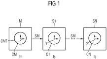
- Fig. 1 Network nodes S1 to SN (common technical term: slaves) are shown, each network node S1 to SN having a corresponding internal clock C1, ..., CN. Each of these clocks works at an individual node clock frequency fs (slave clock frequency), which may be different for different network nodes S1 to SN.
- a reference node M (common technical term: master) is provided, which has a reference clock CM, which is clocked with a reference clock frequency fm, to which all internal clocks C1, ..., CN of the network nodes S1 to SN are to be matched.
- synchronization messages SM are sent out from the reference node M at constant intervals comprising a predetermined number of clocks from the reference clock CM.
- Each of these synchronization messages SM contains a reference clock cycle counter status CMT of the reference clock CM, ie the cycles of the reference clock CM that have already expired during operation of the method.
- This reference clock pulse counter status CMT is transmitted with each synchronization message SM.
- the reference node M and the individual network nodes S1 to SN communicate with one another in a row, with synchronization messages being transmitted from the reference node M to the network node S1 and from there to the network node S2 etc. up to the network node SN.
- the reference clock pulse counter status CMT In order to achieve exact time synchronization in the individual network nodes S1 to SN, the reference clock pulse counter status CMT must be updated in the synchronization messages SM in the individual network nodes S1 to SN.
- a time delay is known in each network node S1 to SN, between the sending of a synchronization message SM from the previous network node S1 to SN (or from the reference node M) until the sending of the synchronization message SM from the respective network node S1 to SN to the next network node S1 to SN is needed.
- the pulse ratio between the reference clock frequency fm and the respective node clock frequency fs must be estimated in the respective network node.
- This clock ratio is also referred to below as RCF (abbreviation for "Rate Compensation Factor”) and is, for example, the quotient of fm and fs.
- the clock ratio RCF is calculated locally in each network node S1 to SN.
- a final pulse ratio RCF can be calculated from the preliminary pulse ratio RCF pre by smoothing.
- the above formula shows that the clock ratio RCF (or the preliminary clock ratio RCF pre ) must change with every frequency deviation of the reference clock frequency fm or the node clock frequency fs of the respective network node S1 to SN.
- the network node S i detects a significant synchronization discrepancy or a significant change in its clock ratio RCF compared to its neighboring network nodes S i-1 and S i + 1 , while the synchronization discrepancy ⁇ S i-1 of the neighboring network node S i-1 corresponds to the synchronization discrepancy ⁇ S i +1 of the neighboring network node S i + 1 is similar, a change in the node clock frequency fs in network node i is the most likely cause.
- the quantitative determination of the threshold value or the similarities, i.e. the parameters of the algorithm, is carried out according to the respective requirements and system properties.
- a frequency change is detected, according to a variant of the exemplary embodiment, it is sent to a central Evaluation unit communicates, which brings together and evaluates the relevant signals from all network nodes.
- the algorithm can also use the synchronization deviations ⁇ S i-1 , ⁇ S i , ⁇ S i + 1 to be a deviation of a reference clock clock counter status RMT compared to the respective network node S i-1 , S i and S i + 1 Evaluate reference clock pulse counter status CMT in a received synchronization message SM.
- the algorithm is carried out, for example, in a microprocessor which, for example, on a network card, e.g. B. a network card with its own real-time clock and time stamp unit can be arranged.
- the algorithm can also be implemented by special hardware or circuitry. Implementing the real-time clock and the time stamp unit in hardware is advantageous because of the high demands on temporal accuracy.
- a system clock of the network node can also be accessed.
- the time synchronization takes place in accordance with the IEC 61158 Type 10 standard, called PROFINET, and alternatively or additionally in accordance with the Precision Transparent Clock Protocol (PTCP) in accordance with IEC 61158 Type 10 PTCP, which is also referenced as a profile in the IEEE 1588 V2 standard becomes.
- the reference node M serves as the master, while the network nodes S1-SN are used as slaves in accordance with the respective standards.
- a multicast network for example an Ethernet, is suitable here as the communication network.
Landscapes
- Engineering & Computer Science (AREA)
- Computer Networks & Wireless Communication (AREA)
- Signal Processing (AREA)
- Synchronisation In Digital Transmission Systems (AREA)
- Small-Scale Networks (AREA)
Description
In einer Vielzahl von technischen Gebieten werden Kommunikationsnetze dazu verwendet, dezentral Arbeitsabläufe zu steuern. Insbesondere in industriellen Automatisierungsanlagen ist von besonderer Bedeutung, dass die automatischen Arbeitsvorgänge genau aufeinander abgestimmt sind. Dies wird dadurch erreicht, dass die einzelnen, miteinander kommunizierenden Netzknoten in dem Kommunikationsnetz jeweils interne Uhren aufweisen und zur Synchronisation aller internen Uhren Synchronisationsnachrichten übertragen werden. Die interne Uhr eines jeweiligen Netzknotens arbeitet hierbei mit einer entsprechenden Knotentaktfrequenz, die für die einzelnen Netzknoten gegebenenfalls unterschiedlich sein kann. Die Synchronisation der Uhren erfolgt auf der Basis einer vorgegebenen Referenzuhr (engl. Bezeichnung: "Grandmaster Clock") bzw. deren Referenztaktfrequenz, wobei die Synchronisationsnachrichten in Abhängigkeit von der Referenztaktfrequenz übertragen werden. Dies bedeutet, dass in festen Taktabständen gemäß der Referenztaktfrequenz Synchronisationsnachrichten übermittelt werden. Die einzelnen, im Kommunikationsnetz übertragenen Synchronisationsnachrichten enthalten den Taktzählzustand der Referenzuhr. Jeder Netzknoten aktualisiert diesen Taktzählzustand für den eigenen Bedarf, indem er die Anzahl an Takten der Referenzuhr zwischen Aussenden der Synchronisationsnachricht beim vorhergehenden Netzknoten und Empfangen der Synchronisationsnachricht beim jeweiligen Netzknoten abschätzt (engl. Bezeichnung "line delay"). Außerdem aktualisiert jeder Netzknoten diesen Taktzählzustand für den nächsten Knoten, indem er auch die Anzahl an Takten der Referenzuhr zwischen seinem Empfangen der Synchronisationsnachricht und seinem Aussenden der Synchronisationsnachricht abschätzt (engl. Bezeichnung "bridge delay"). Diese Abschätzung erfolgt u. a. üblicherweise dadurch, dass das Taktverhältnis (im Englischen auch als "Rate Compensation Factor" RCF bezeichnet) zwischen der Referenztaktfrequenz und der Knotentaktfrequenz des jeweiligen Netzknotens abgeschätzt wird. Mit dem abgeschätzten Taktverhältnis kann dann für jede gewünschte Zeitspanne eine Umrechnung der Anzahl an Takten der Knotentaktfrequenz in die entsprechende Anzahl der Referenztaktfrequenz durchgeführt werden. Zum Beispiel kann damit eine Umrechnung der Zeitspanne zwischen Aussenden einer Synchronisationsnachricht beim vorhergehenden Netzknoten und Aussenden der Synchronisationsnachricht beim jeweiligen Netzknoten, gemessen in Takten der Knotentaktfrequenz, in die Takte der Referenztaktfrequenz durchgeführt werden. Die sich daraus ergebende Anzahl an Takten wird dann zu den Takten der empfangenen Synchronisationsnachricht hinzuaddiert und eine entsprechend aktualisierte Synchronisationsnachricht wird von dem entsprechenden Netzknoten wieder ausgesendet.In a large number of technical areas, communication networks are used to control work processes in a decentralized manner. In industrial automation systems in particular, it is of particular importance that the automatic work processes are precisely coordinated with one another. This is achieved in that the individual network nodes communicating with one another in the communication network each have internal clocks and synchronization messages are transmitted to synchronize all internal clocks. The internal clock of a respective network node works here with a corresponding node clock frequency, which may be different for the individual network nodes. The clocks are synchronized on the basis of a predetermined reference clock (English designation: "Grandmaster Clock") or its reference clock frequency, with the synchronization messages being transmitted as a function of the reference clock frequency. This means that synchronization messages are transmitted at fixed clock intervals according to the reference clock frequency. The individual synchronization messages transmitted in the communication network contain the cycle count status of the reference clock. Each network node updates this cycle count status for its own needs by estimating the number of cycles of the reference clock between sending the synchronization message at the previous network node and receiving the synchronization message at the respective network node (term "line delay"). In addition, each network node updates this cycle count status for the next node by also estimating the number of cycles of the reference clock between its receipt of the synchronization message and its transmission of the synchronization message (English term "bridge delay"). This estimation is usually carried out, among other things, by the fact that the clock ratio (also referred to as "Rate Compensation Factor" RCF) between the reference clock frequency and the node clock frequency of the respective network node is estimated. With the estimated clock ratio, a conversion of the number of clock pulses of the node clock frequency into the corresponding number of the reference clock frequency can then be carried out for any desired period of time. For example, a conversion of the time span between sending a synchronization message at the preceding network node and sending the synchronization message at the respective network node, measured in clocks of the node clock frequency, can be carried out into the clocks of the reference clock frequency. The resulting number of clocks is then added to the clocks of the received synchronization message and a correspondingly updated synchronization message is sent out again from the corresponding network node.
Aus dem Stand der Technik ist im Bereich der industriellen Automatisierungstechnik der Standard IEC 61158 Type 10 bekannt, genannt PROFINET, bei dem es sich um ein Ethernet handelt, welches industriellen Vorgaben genügt. Dieser PROFINET Standard arbeitet nach dem oben dargelegten Prinzip, wonach in den Netzknoten die Taktzählzustände in den Synchronisationsnachrichten aktualisiert werden. Auf PROFINET basierte Systeme verwenden zur Synchronisation der internen Uhren der Netzknoten üblicherweise das Precision Transparent Clock Protocol (PTCP) gemäß IEC 61158 Type 10 PTCP, welches auch im Standard IEEE 1588 V2 als Profil referenziert wird.The standard IEC 61158 Type 10 is known from the prior art in the field of industrial automation technology, called PROFINET, which is an Ethernet that meets industrial requirements. This PROFINET standard works according to the principle set out above, according to which the cycle count statuses in the synchronization messages are updated in the network nodes. Systems based on PROFINET usually use the Precision Transparent Clock Protocol (PTCP) in accordance with IEC 61158 Type 10 PTCP, which is also referenced as a profile in the IEEE 1588 V2 standard, to synchronize the internal clocks of the network nodes.
Dieses aktualisiert nach dem oben dargelegten Prinzip die Taktzählzustände der Synchronisationsnachrichten. Gemäß diesem Standard werden aufeinanderfolgend Synchronisationsnachrichten von einem Netzknoten zum nächsten in einer logischen Reihe oder Baumstruktur übertragen. Die Synchronisationsnachrichten stammen von einem Referenzknoten bzw. Masterelement, welches das erste Element in der Reihe bzw. in der Baumstruktur ist. Die Synchronisationsnachrichten enthalten ursprünglich einen Zeitstempel des Zählers einer Referenzuhr in dem Referenzknoten, wenn eine Synchronisationsnachricht übertragen wurde. Die Netzknoten in der Reihe bzw. Baumstruktur, auch genannt Slaves, verarbeiten diese Information und senden sie weiter. Ein Netzknoten fügt hierbei alle abgeschätzten Zeitverzögerungen zwischen dem Aussenden einer Synchronisationsnachricht vom vorhergehenden Netzknoten und seinem eigenen Aussenden der Synchronisationsnachricht als Inhalt der Synchronisationsnachricht hinzu.This updates the clock counting states of the synchronization messages according to the principle set out above. According to this standard, synchronization messages are successively transmitted from one network node to the next in a logical series or tree structure. The synchronization messages come from a reference node or master element, which is the first element in the series or in the tree structure. The synchronization messages originally contain a time stamp of the counter of a reference clock in the reference node when a synchronization message was transmitted. The network nodes in the row or tree structure, also called slaves, process this information and send it on. A network node adds all estimated time delays between the transmission of a synchronization message from the previous network node and its own transmission of the synchronization message as the content of the synchronization message.
Eine konkrete Implementierung ist beschrieben in
Aus dem Stand der Technik ist folgendes Dokument bekannt:
Aus der
Aus der
Es wird somit für den eigenen Bedarf jedes Netzknotens (nicht aber für das Weiterleiten zum nächsten Netzknoten) nicht mehr der geschätzte Referenzuhr-Taktzählzustand als Schätzung des Referenzuhr-Taktzählzustands verwendet, sondern vielmehr der geregelte Taktzählzustand, welcher durch eine Verfolgung des geschätzten Referenzuhr-Taktzählzustands mit dem Regler ermittelt wird. Somit werden die Sprünge des geschätzten Referenzuhr-Taktzählzustands bei Neuberechnung nach Erhalt einer Synchronisationsnachricht, welche in vielen industriellen Anwendungen nicht tolerierbar sind, in den stetigen Verlauf des geregelten Taktzählzustands umgewandelt. Störungen von zeitabhängigen Prozessen werden somit reduziert. Darüber hinaus weist der geregelte Taktzählzustand im Mittel eine geringere Abweichung vom Referenzuhr-Taktzählzustand auf als der geschätzte Referenzuhr-Taktzählzustand.For each network node's own needs (but not for forwarding to the next network node), the estimated reference clock pulse count status is no longer used as an estimate of the reference clock pulse count status, but rather the regulated pulse count status, which is also used by tracking the estimated reference clock pulse count status is determined by the controller. Thus, the jumps in the estimated reference clock cycle count status when recalculated after receipt of a synchronization message, which cannot be tolerated in many industrial applications, are converted into the constant course of the regulated cycle count status. Disturbances of time-dependent processes are thus reduced. In addition, the regulated cycle counting state has, on average, a smaller deviation from the reference clock / cycle counting status than the estimated reference clock / cycle counting status.
Durch die vorliegende Erfindung soll die Gefahr von Störungen zeitabhängiger Prozesse durch mangelnde Synchronisation der Netzknoten weiter verringert werden.The present invention is intended to further reduce the risk of malfunctions in time-dependent processes due to insufficient synchronization of the network nodes.
Diese Aufgabe wird durch ein Verfahren zur Lokalisierung einer Frequenzabweichung in einem Kommunikationsnetz gelöst,
- bei dem das Kommunikationsnetz eine Vielzahl von miteinander kommunizierenden Netzknoten umfasst, welche jeweils eine interne Uhr beinhalten, welche mit einer dem jeweiligen Netzknoten zugeordneten Knotentaktfrequenz getaktet ist,
- bei dem Synchronisationsnachrichten in dem Kommunikationsnetz übertragen werden, welche zur Zeitsynchronisation der internen Uhren der Netzknoten dienen,
- bei dem die Synchronisationsnachrichten aufeinander folgend von einem vorhergehenden Netzknoten zu einem mittleren Netzknoten und von diesem zu einem nächsten Netzknoten in Abhängigkeit von einer durch eine Referenzuhr vorgegebenen Referenztaktfrequenz übermittelt werden, wobei die Synchronisationsnachrichten den Referenzuhr-Taktzählzustands der Referenzuhr beinhalten;
- der vorhergehende Netzknoten, der mittlere Netzknoten und der nächste Netzknoten in vorgegebenen zeitlichen Abständen jeweils eine Synchronisationsabweichung berechnen;
- der mittlere Netzknoten folgenden Algorithmus ausführt, sofern seine zuletzt ermittelte Synchronisationsabweichung einen Schwellwert überschreitet:
- Detektion einer Veränderung der Referenztaktfrequenz, sofern die Synchronisationsabweichungen, welche der vorhergehende Netzknoten, der mittlere Netzknoten und der nächste Netzknoten berechnet haben, zueinander ähnlich sind, und andernfalls
- Detektion einer Veränderung der Knotentaktfrequenz des mittleren Netzknotens, sofern die Synchronisationsabweichungen, welche der vorhergehende Netzknoten und der nächste Netzknoten berechnet haben, zueinander ähnlich sind.
- in which the communication network comprises a plurality of network nodes communicating with one another, each of which contains an internal clock that is clocked with a node clock frequency assigned to the respective network node,
- in which synchronization messages are transmitted in the communication network, which are used to synchronize the internal clocks of the network nodes,
- in which the synchronization messages are successively transmitted from a preceding network node to a central network node and from this to a next network node as a function of a reference clock frequency predetermined by a reference clock, the synchronization messages containing the reference clock pulse count status of the reference clock;
- the previous network node, the middle network node and the next network node each calculate a synchronization deviation at predetermined time intervals;
- the middle network node executes the following algorithm if its last determined synchronization deviation exceeds a threshold value:
- Detection of a change in the reference clock frequency, provided that the synchronization deviations calculated by the previous network node, the middle network node and the next network node are similar to one another, and otherwise
- Detection of a change in the node clock frequency of the middle network node, provided that the synchronization deviations calculated by the previous network node and the next network node are similar to one another.
Die Aufgabe wird ferner durch ein Kommunikationsnetz zur Lokalisierung einer Frequenzabweichung gelöst,
- umfassend eine Vielzahl von miteinander kommunizierenden Netzknoten, welche jeweils eine interne Uhr beinhalten, welche mit einer dem jeweiligen Netzknoten zugeordneten Knotentaktfrequenz getaktet ist,
- eingerichtet zur Übertragung von Synchronisationsnachrichten, welche zur Zeitsynchronisation der internen Uhren der Netzknoten dienen,
- eingerichtet zur Übermittlung der Synchronisationsnachrichten aufeinander folgend von einem vorhergehenden Netzknoten zu einem mittleren Netzknoten und von diesem zu einem nächsten Netzknoten in Abhängigkeit von einer durch eine Referenzuhr vorgegebenen Referenztaktfrequenz, wobei die Synchronisationsnachrichten den Referenzuhr-Taktzählzustands der Referenzuhr beinhalten,
- wobei der vorhergehende Netzknoten, der mittlere Netzknoten und der nächste Netzknoten eingerichtet sind, in vorgegebenen zeitlichen Abständen jeweils eine Synchronisationsabweichung zu berechnen;
- wobei der mittlere Netzknoten zur Ausführung des folgenden Algorithmus eingerichtet ist, sofern seine zuletzt ermittelte Synchronisationsabweichung einen Schwellwert überschreitet:
- Detektion einer Veränderung der Referenztaktfrequenz, sofern die Synchronisationsabweichungen, welche der vorhergehende Netzknoten, der mittlere Netzknoten und der nächste Netzknoten berechnet haben, zueinander ähnlich sind, und andernfalls
- Detektion einer Veränderung der Knotentaktfrequenz des mittleren Netzknotens, sofern die Synchronisationsabweichungen, welche der vorhergehende Netzknoten und der nächste Netzknoten berechnet haben, zueinander ähnlich sind.
- comprising a multiplicity of network nodes communicating with one another, each of which contains an internal clock which is clocked with a node clock frequency assigned to the respective network node,
- set up for the transmission of synchronization messages, which are used to synchronize the internal clocks of the network nodes,
- set up to transmit the synchronization messages in succession from a preceding network node to a middle network node and from this to one next network node as a function of a reference clock frequency specified by a reference clock, the synchronization messages containing the reference clock pulse count status of the reference clock,
- wherein the previous network node, the middle network node and the next network node are set up to calculate a synchronization deviation at predetermined time intervals;
- The middle network node is set up to execute the following algorithm, provided that its last determined synchronization deviation exceeds a threshold value:
- Detection of a change in the reference clock frequency, provided that the synchronization deviations calculated by the previous network node, the middle network node and the next network node are similar to one another, and otherwise
- Detection of a change in the node clock frequency of the middle network node, provided that the synchronization deviations calculated by the previous network node and the next network node are similar to one another.
Neben dem soeben beschriebenen Verfahren und der Vorrichtung umfasst die Erfindung ferner einen computerlesbaren Datenträger, auf dem ein Computerprogramm gespeichert ist, welches das soeben beschriebene Verfahren ausführt, wenn es in einem Mikroprozessor abgearbeitet wird.In addition to the method and the device just described, the invention also comprises a computer-readable data carrier on which a computer program is stored which executes the method just described when it is processed in a microprocessor.
Weiterhin umfasst die Erfindung ein Computerprogramm, das in einem Mikroprozessor abgearbeitet wird und dabei das zuvor beschriebene Verfahren ausführt.The invention further comprises a computer program which is processed in a microprocessor and thereby executes the method described above.
Die im Folgenden genannten Vorteile müssen nicht notwendigerweise durch die Gegenstände der unabhängigen Patentansprüche erzielt werden. Vielmehr kann es sich hierbei auch um Vorteile handeln, welche lediglich durch einzelne Ausführungsformen, Varianten oder Weiterbildungen erzielt werdenThe advantages mentioned below do not necessarily have to be achieved by the subject matter of the independent patent claims. Rather, these can also be advantages that can only be achieved through individual embodiments, variants or developments
Das Verfahren und das Kommunikationsnetz erlauben es, eine starke Frequenzabweichung im Kommunikationsnetz durch die Untersuchung der Synchronisationsabweichungen in benachbarten Netzknoten unmittelbar zu erkennen und zu lokalisieren. Neben einer Frequenzabweichung der Referenzuhr kann auch eine Frequenzabweichung in der internen Uhr jedes anderen Netzknotens ermittelt werden, sofern das Verfahren von allen Netzknoten ausgeführt wird.The method and the communication network make it possible to directly identify and localize a strong frequency deviation in the communication network by examining the synchronization deviations in neighboring network nodes. In addition to a frequency deviation in the reference clock, a frequency deviation in the internal clock of every other network node can also be determined, provided that the method is carried out by all network nodes.
Eine Frequenzabweichung kann beispielsweise auf äußere Einflüsse zurückzuführen sein. Eine zeitnahe Detektion hat folgende Vorteile:
- 1. Eine Frequenzabweichung einer internen Uhr eines Netzknotens beeinträchtigt vorübergehend die Qualität seiner Schätzung des Referenzuhr-Taktzählzustands, bis der Netzknoten sein Taktverhältnis und seinen internen Regler vollständig an die Abweichung angepasst hat. Aus der Detektion der Frequenzabweichung ergibt sich folglich ein Maß für die Güte der Zeitschätzung in diesem Netzknoten.
- 2. Eine Frequenzabweichung der Referenzuhr hat wesentlich gravierendere Effekte. Da sämtliche Netzknoten bemüht sind, der Referenzuhr zu folgen, bleiben sie in ihrer Adaption hinter der Referenzuhr zurück, sodass die Qualität der Synchronisierung im gesamten Kommunikationsnetz abnimmt. Erschwerend kommt hinzu, dass sich die Adaption in Abhängigkeit von der Entfernung zur Referenzuhr zunehmend verzögert. Dies verschlechtert nicht nur die Synchronisierung der Netzknoten mit der Referenzuhr, sondern auch die Synchronisierung der Netzknoten untereinander. Der schnellen Detektion einer Frequenzabweichung der Referenzuhr kommt somit große Bedeutung zu.
- 3. Die äußere Störung, welche die Frequenzabweichung verursacht, kann auf einen Systemfehler oder einen Einbruch in das Kommunikationsnetz zurückzuführen sein. Die genaue Lokalisierung des betroffenen Netzknotens unterstützt die zeitnahe Ermittlung und Bekämpfung des Systemfehlers oder Einbruchs.
- 1. A frequency deviation of an internal clock of a network node temporarily affects the quality of its estimate of the reference clock cycle counter status until the network node has completely adapted its cycle ratio and its internal controller to the deviation. The detection of the frequency deviation consequently results in a measure of the quality of the time estimate in this network node.
- 2. A frequency deviation of the reference clock has much more serious effects. Since all network nodes try to follow the reference clock, they lag behind the reference clock in their adaptation, so that the quality of the synchronization in the entire communication network decreases. To make matters worse, the adaptation is increasingly delayed depending on the distance to the reference clock. This not only worsens the synchronization of the network nodes with the reference clock, but also the synchronization of the network nodes with one another. The rapid detection of a frequency deviation of the reference clock is therefore of great importance.
- 3. The external disturbance which causes the frequency deviation can be traced back to a system error or an intrusion into the communication network. The exact localization of the affected network node supports the prompt determination and control of system errors or intrusions.
Gemäß einer Ausführungsform ergibt sich ein Verfahren,
- bei dem als Synchronisationsabweichung eines Netzknotens eine Änderung eines Taktverhältnis zwischen der Referenztaktfrequenz und seiner Knotentaktfrequenz basierend auf in der Vergangenheit empfangenen Synchronisationsnachrichten berechnet wird.
- in which a change in a clock ratio between the reference clock frequency and its node clock frequency based on synchronization messages received in the past is calculated as a synchronization deviation of a network node.
In einer Weiterbildung ergibt sich ein Verfahren,
- bei dem jeder Netzknoten zur Ermittlung eines geschätzten Referenzuhr-Taktzählzustands eingerichtet ist, welcher eine Schätzung des Referenzuhr-Taktzählzustands der Referenzuhr darstellt,
- bei dem als Synchronisationsabweichung eines Netzknotens eine Abweichung seines geschätzten Referenzuhr-Taktzählzustands gegenüber dem Referenzuhr-Taktzählzustands in einer empfangenen Synchronisationsnachricht berechnet wird.
- in which each network node is set up to determine an estimated reference clock-pulse count status, which represents an estimate of the reference clock-pulse count status of the reference clock,
- in which the synchronization deviation of a network node is calculated as a deviation of its estimated reference clock-pulse count status compared to the reference clock-pulse count status in a received synchronization message.
Vorteilhafterweise wird hier ein Fehler zwischen den benachbarten Netzwerkknoten ausgetauscht, welcher sich aus der Differenz des geschätzten Referenzuhr-Taktzählzustands und des Referenzuhr-Taktzählzustands aus der zuletzt empfangenen Synchronisationsnachricht ergibt.Advantageously, an error is exchanged here between the neighboring network nodes which results from the difference between the estimated reference clock / pulse count status and the reference clock / pulse count status from the synchronization message last received.
Gemäß einer Ausführungsform ergibt sich ein Verfahren,
- bei dem das Ergebnis der Detektion an eine zentrale Auswertungseinheit übertragen wird.
- in which the result of the detection is transmitted to a central evaluation unit.
Dies ermöglicht eine schnelle zentrale Detektion von Frequenzabweichungen, auf die sofort reagiert werden kann.This enables rapid central detection of frequency deviations, which can be responded to immediately.
In einer Weiterbildung ergibt sich ein Verfahren,
- bei dem die Zeitsynchronisation nach dem Standard IEC 61158 Type 10, genannt PROFINET, und/oder dem Precision Transparent Clock Protocol gemäß dem Standard IEC 61158 Type 10 PTCP erfolgt, wobei der Referenzknoten als Master und die Netzknoten als Slaves gemäß den jeweiligen Standards verwendet werden, und wobei das Kommunikationsnetz ein Multicast-Netzwerk, insbesondere ein Ethernet, ist.
- in which the time synchronization takes place in accordance with the IEC 61158 Type 10 standard, called PROFINET, and / or the Precision Transparent Clock Protocol in accordance with the IEC 61158 Type 10 PTCP standard, with the reference node as the master and the network nodes are used as slaves in accordance with the respective standards, and the communication network is a multicast network, in particular an Ethernet.
Das Verfahren und das Kommunikationsnetz erlauben die einfache Adaption der bereits bisher eingesetzten Protokolle, um Synchronisationsabweichungen von benachbarten Netzwerkknoten auszuwerten.The method and the communication network allow the protocols already used to be easily adapted in order to evaluate synchronization deviations from neighboring network nodes.
Gemäß einer Ausführungsform ergibt sich ein Kommunikationsnetz,
- bei dem der mittlere Netzknoten eine Netzwerkkarte, insbesondere eine Netzwerkkarte mit eigener Echtzeit-Uhr und Zeitstempel-Einheit, enthält oder aus ihr besteht.
- in which the middle network node contains or consists of a network card, in particular a network card with its own real-time clock and time stamp unit.
Das erfindungsgemäße Verfahren wird vorzugsweise in einer industriellen Automatisierungsanlage eingesetzt, bei der verteilte Komponenten der Anlage miteinander kommunizieren, um Fertigungsabläufe, z.B. bei der Automobilherstellung, zu steuern. Hierzu kommunizieren die einzelnen Komponenten über ein Kommunikationsnetz drahtlos und/oder drahtgebunden miteinander. Die Komponenten stellen somit Netzknoten des Kommunikationsnetzes dar.The method according to the invention is preferably used in an industrial automation system in which distributed components of the system communicate with one another in order to control production processes, e.g. in the manufacture of automobiles. For this purpose, the individual components communicate wirelessly and / or wired with one another via a communication network. The components thus represent network nodes of the communication network.
Ausführungsbeispiele der Erfindung werden nachfolgend anhand der beigefügten Figuren detailliert beschrieben. In den Figuren sind gleiche oder funktionsgleiche Elemente mit denselben Bezugszeichen versehen, sofern nichts anderes angegeben ist.Exemplary embodiments of the invention are described in detail below with reference to the accompanying figures. In the figures, elements that are the same or have the same function are provided with the same reference symbols, unless otherwise stated.
Es zeigen:
- Fig. 1
- eine schematische Darstellung einer Mehrzahl von Netzknoten in einem Kommunikationsnetz, zwischen denen Synchronisationsnachrichten übermittelt werden (Stand der Technik);
- Fig. 2
- eine schematische Darstellung einer Mehrzahl von Netzknoten in einem Kommunikationsnetz, welche eine Frequenzabweichung lokalisieren.
- Fig. 1
- a schematic representation of a plurality of network nodes in a communication network, between which synchronization messages are transmitted (prior art);
- Fig. 2
- a schematic representation of a plurality of network nodes in a communication network, which localize a frequency deviation.
In
Der Referenzknoten M und die einzelnen Netzknoten S1 bis SN kommunizieren in einer Reihe miteinander, wobei Synchronisationsnachrichten vom Referenzknoten M an den Netzknoten S1 und von diesem an den Netzknoten S2 usw. bis zum Netzknoten SN übermittelt werden. Um eine exakte Zeitsynchronisation in den einzelnen Netzknoten S1 bis SN zu erreichen, muss der Referenzuhr-Taktzählzustand CMT in den Synchronisationsnachrichten SM in den einzelnen Netzknoten S1 bis SN aktualisiert werden. Deshalb ist in jedem Netzknoten S1 bis SN eine Zeitverzögerung bekannt, die zwischen dem Aussenden einer Synchronisationsnachricht SM vom vorhergehenden Netzknoten S1 bis SN (bzw. vom Referenzknoten M) bis zum Aussenden der Synchronisationsnachricht SM vom jeweiligen Netzknoten S1 bis SN zum nächsten Netzknoten S1 bis SN benötigt wird. Diese Zeitverzögerung setzt sich aus zwei Zeitspannen LDi und BDi (i = 1, ..., N, zu dieser Art der Nummerierung der Netzknoten vgl. auch
Um nunmehr den Referenzuhr-Taktzählzustand CMT einer empfangenen Synchronisationsnachricht SM zu aktualisieren, ist in dem jeweiligen Netzknoten das Taktverhältnis zwischen der Referenztaktfrequenz fm und der jeweiligen Knotentaktfrequenz fs abzuschätzen. Dieses Taktverhältnis wird nachfolgend auch als RCF (Abkürzung für engl. "Rate Compensation Factor") bezeichnet und ist beispielsweise der Quotient aus fm und fs. Durch Multiplikation des abgeschätzten Taktverhältnisses RCF mit der Zeitverzögerung erhält man die Anzahl von Zähltakten beim Wiederaussenden der zuvor empfangenen Synchronisationsnachricht SM. Diese Anzahl wird zu dem Referenzuhr-Taktzählzustand CMT der empfangenen Synchronisationsnachricht SM hinzuaddiert, und eine Synchronisationsnachricht SM mit diesem aktuellen Referenzuhr-Taktzählzustand CMT wird von dem jeweiligen Netzknoten ausgesendet. Der Ablauf der Synchronisation der internen Uhren C1 bis CN ist hierbei dem Fachmann hinlänglich bekannt und wird deshalb nicht im Detail erläutert.In order to update the reference clock pulse count status CMT of a received synchronization message SM, the pulse ratio between the reference clock frequency fm and the respective node clock frequency fs must be estimated in the respective network node. This clock ratio is also referred to below as RCF (abbreviation for "Rate Compensation Factor") and is, for example, the quotient of fm and fs. By multiplying the estimated clock ratio RCF by the time delay, the number of counting clocks when retransmitting the previously received synchronization message SM is obtained. This number is added to the reference clock pulse count status CMT of the received synchronization message SM, and a synchronization message SM with this current reference clock pulse count status CMT is sent out by the respective network node. The process of synchronizing the internal clocks C1 to CN is sufficiently known to the person skilled in the art and is therefore not explained in detail.
Das Taktverhältnis RCF wird lokal in jedem Netzknoten S1 bis SN berechnet. Ein vorläufiges Taktverhältnis RCFpre berechnet sich aus ![]()
![]()
Aus dem vorläufigen Taktverhältnis RCFpre kann ein endgültiges Taktverhältnis RCF durch Glättung berechnet werden.A final pulse ratio RCF can be calculated from the preliminary pulse ratio RCF pre by smoothing.
Aus der obigen Formel ergibt sich, dass sich das Taktverhältnis RCF (bzw. das vorläufige Taktverhältnis RCFpre ) mit jeder Frequenzabweichung der Referenztaktfrequenz fm oder der Knotentaktfrequenz fs des jeweiligen Netzknotens S1 bis SN ändern muss.The above formula shows that the clock ratio RCF (or the preliminary clock ratio RCF pre ) must change with every frequency deviation of the reference clock frequency fm or the node clock frequency fs of the respective network node S1 to SN.
Gemäß dem in
- a) eine identische Änderung der Knotentaktfrequenz fs in den Netzknoten Si-1, Si und Si+1, oder
- b) eine Änderung der Referenztaktfrequenz fm.
- a) an identical change in the node clock frequency fs in the network nodes S i-1 , S i and S i + 1 , or
- b) a change in the reference clock frequency fm.
Während die Wahrscheinlichkeit, identische Änderungen des Taktverhältnisses RCF bzw. identische Synchronisationsabweichungen ΔSi-1, ΔSi, ΔSi+1 in den Netzknoten Si-1, Si und Si+1 zu beobachten in beiden Fällen bei 1 liegt, ist die die A-priori-Wahrscheinlichkeit einer Frequenzänderung ausschließlich in der Referenzuhr CM deutlich höher als eine identische Frequenzänderung in den Netzknoten Si-1, Si und Si+1. Unter Rückgriff auf den Satz von Bayes lässt sich somit entscheiden, dass die signifikante Änderung des Taktverhältnisses RCF im Netzknoten Si mit größter Wahrscheinlichkeit durch eine Änderung der Referenztaktfrequenz fm verursacht ist.While the probability of identical changes in the clock ratio RCF or identical synchronization deviations ΔS i-1 , ΔS i , ΔS i + 1 in the network nodes S i-1 , S i and S i + 1 increases observe is 1 in both cases, the a priori probability of a frequency change exclusively in the reference clock CM is significantly higher than an identical frequency change in the network nodes S i-1 , S i and S i + 1 . Using Bayes' theorem, it can thus be decided that the significant change in the clock ratio RCF in the network node S i is most likely caused by a change in the reference clock frequency fm.
Wenn hingegen der Netzknoten Si eine signifikante Synchronisationsabweichung bzw. eine signifikante Änderung seines Taktverhältnisses RCF gegenüber seinen benachbarten Netzknoten Si-1 und Si+1 feststellt, während die Synchronisationsabweichung ΔSi-1 des benachbarten Netzknoten Si-1 der Synchronisationsabweichung ΔSi+1 des benachbarten Netzknoten Si+1 ähnelt, so ist eine Änderung der Knotentaktfrequenz fs im Netzknoten i die wahrscheinlichste Ursache.If, on the other hand, the network node S i detects a significant synchronization discrepancy or a significant change in its clock ratio RCF compared to its neighboring network nodes S i-1 and S i + 1 , while the synchronization discrepancy ΔS i-1 of the neighboring network node S i-1 corresponds to the synchronization discrepancy ΔS i +1 of the neighboring network node S i + 1 is similar, a change in the node clock frequency fs in network node i is the most likely cause.
Der gemäß dem vorliegenden Ausführungsbeispiel aus diesen Beobachtungen abgeleitete Diagnose-Algorithmus wird in geeigneten Zeitintervallen ausgeführt und arbeitet wie folgt:

Die quantitative Bestimmung des Schwellwert bzw. der Ähnlichkeiten, d.h. der Parameter der Algorithmus, erfolgt entsprechend den jeweiligen Anforderungen und Systemeigenschaften.The quantitative determination of the threshold value or the similarities, i.e. the parameters of the algorithm, is carried out according to the respective requirements and system properties.
Sofern eine Frequenzänderung detektiert wird, wird diese gemäß einer Variante des Ausführungsbeispiels an eine zentrale Auswertungseinheit kommuniziert, welche die diesbezüglichen Signale aller Netzknoten zusammenführt und evaluiert.If a frequency change is detected, according to a variant of the exemplary embodiment, it is sent to a central Evaluation unit communicates, which brings together and evaluates the relevant signals from all network nodes.
Anstelle der Abweichungen des Taktverhältnisses RCF kann der Algorithmus als Synchronisationsabweichungen ΔSi-1, ΔSi, ΔSi+1 auch eine Abweichung eines durch den jeweiligen Netzknoten Si-1, Si und Si+1 geschätzten Referenzuhr-Taktzählzustands RMT gegenüber dem Referenzuhr-Taktzählzustand CMT in einer empfangenen Synchronisationsnachricht SM auswerten.Instead of the deviations in the clock ratio RCF, the algorithm can also use the synchronization deviations ΔS i-1 , ΔS i , ΔS i + 1 to be a deviation of a reference clock clock counter status RMT compared to the respective network node S i-1 , S i and S i + 1 Evaluate reference clock pulse counter status CMT in a received synchronization message SM.
Der Algorithmus wird beispielsweise in einem Mikroprozessor ausgeführt, welcher beispielsweise auf einer Netzwerkkarte, z. B. einer Netzwerkkarte mit eigener Echtzeit-Uhr und Zeitstempel-Einheit, angeordnet sein kann. Der Algorithmus kann auch durch eine spezielle Hardware oder Schaltung implementiert werden. Eine Ausführung der Echtzeit-Uhr und der Zeitstempel-Einheit in Hardware ist wegen der hohen Anforderungen an zeitliche Genauigkeit von Vorteil. Alternativ zu der Echtzeit-Uhr auf der Netzwerkkarte kann auch auf eine System-Uhr des Netzknotens zugegriffen werden.The algorithm is carried out, for example, in a microprocessor which, for example, on a network card, e.g. B. a network card with its own real-time clock and time stamp unit can be arranged. The algorithm can also be implemented by special hardware or circuitry. Implementing the real-time clock and the time stamp unit in hardware is advantageous because of the high demands on temporal accuracy. As an alternative to the real-time clock on the network card, a system clock of the network node can also be accessed.
In einer Weiterbildung der beschriebenen Ausführungsbeispiele erfolgt die Zeitsynchronisation nach dem Standard IEC 61158 Type 10, genannt PROFINET, und alternativ oder ergänzend nach dem Precision Transparent Clock Protocol (PTCP) gemäß IEC 61158 Type 10 PTCP, welches auch im Standard IEEE 1588 V2 als Profil referenziert wird. Hierbei dient der Referenzknoten M als Master, während die Netzknoten S1-SN als Slaves gemäß den jeweiligen Standards verwendet werden. Als Kommunikationsnetz eignet sich hier ein Multicast-Netzwerk, beispielsweise ein Ethernet.In a further development of the exemplary embodiments described, the time synchronization takes place in accordance with the IEC 61158 Type 10 standard, called PROFINET, and alternatively or additionally in accordance with the Precision Transparent Clock Protocol (PTCP) in accordance with IEC 61158 Type 10 PTCP, which is also referenced as a profile in the IEEE 1588 V2 standard becomes. Here, the reference node M serves as the master, while the network nodes S1-SN are used as slaves in accordance with the respective standards. A multicast network, for example an Ethernet, is suitable here as the communication network.
Obwohl die Erfindung im Detail durch die Ausführungsbeispiele näher illustriert und beschrieben wurde, so ist die Erfindung nicht durch die offenbarten Beispiele eingeschränkt und andere Variationen können vom Fachmann hieraus abgeleitet werden, ohne den Schutzumfang der Erfindung zu verlassen. Die beschriebenen Ausführungsbeispiele, Varianten, Ausführungsformen und Weiterbildungen sind frei miteinander kombinierbar.Although the invention has been illustrated and described in more detail by the exemplary embodiments, the invention is not restricted by the disclosed examples and other variations can be derived therefrom by the person skilled in the art without departing from the scope of protection of the invention. The exemplary embodiments, variants, embodiments and developments described can be freely combined with one another.
Claims (9)
- Method for locating a frequency deviation in a communication network,- in which the communication network comprises a multiplicity of network nodes (S1, ..., SN) which communicate with one another and each comprise an internal clock (C1, ..., CN) which is clocked at a node clock frequency (fs) assigned to the respective network node (S1, ..., SN),- in which synchronization messages (SM) which are used for the time synchronization of the internal clocks (C1, ..., CN) of the network nodes (S1, ..., SN) are transmitted in the communication network,- in which the synchronization messages (SM) are transmitted in succession from a preceding network node (Si-1) to a middle network node (Si) and, from the latter, to a next network node (Si+1) on the basis of a reference clock frequency (fm) predefined by a reference clock (CM), the synchronization messages (SM) comprising the reference clock count state (CMT) of the reference clock (CM);- the preceding network node (Si-1), the middle network node (Si) and the next network node (Si+1) each calculate a synchronization deviation (ΔSi-1, ΔSi, ΔSi+1) at predefined intervals of time;- the middle network node (Si) carries out the following algorithm if its synchronization deviation (ΔSi) determined last exceeds a threshold value:- detecting a change in the reference clock frequency (fm) if the synchronization deviations (ΔSi-1, ΔSi, ΔSi+1) which have been calculated by the preceding network node (Si-1), the middle network node (Si) and the next network node (Si+1) are similar to one another, and otherwise- detecting a change in the node clock frequency (fs) of the middle network node (Si) if the synchronization deviations (ΔSi-1, ΔSi+1) which have been calculated by the preceding network node (Si-1) and the next network node (Si+1) are similar to one another.
- Method according to Claim 1,- in which a change in a clock ratio (RCF) between the reference clock frequency (fm) and the node clock frequency (fs) of a network node is calculated as the synchronization deviation (ΔS1, ..., ΔSN) of a network node (S1, ..., SN) on the basis of synchronization messages (SM) received in the past.
- Method according to Claim 1,- in which each network node (S1, ..., SN) is set up to determine an estimated reference clock count state (RMT) which represents an estimation of the reference clock count state (CMT) of the reference clock (CM),- in which a deviation of the reference clock count state (RMT) estimated by a network node from the reference clock count state (CMT) in a received synchronization message (SM) is calculated as the synchronization deviation (ΔS1, ..., ΔSN) of a network node (S1, ..., SN).
- Method according to one of the preceding claims,- in which the detection result is transmitted to a central evaluation unit.
- Method according to one of the preceding claims,- in which the time synchronization is carried out according to the IEC 61158 Type 10 standard (called PROFINET) and/or the Precision Transparent Clock Protocol according to the IEC 61158 Type 10 PTCP standard, the reference node (M) being used as the master and the network nodes (S1, ..., SN) being used as slaves according to the respective standards, and the communication network being a multicast network, in particular an Ethernet.
- Communication network- comprising a multiplicity of network nodes (S1, ..., SN) which communicate with one another and each comprise an internal clock (C1, ..., CN) which is clocked at a node clock frequency (fs) assigned to the respective network node (S1, ..., SN),- set up to transmit synchronization messages (SM) which are used for the time synchronization of the internal clocks (C1, ..., CN) of the network nodes (S1, ..., SN),- set up to transmit the synchronization messages (SM) in succession from a preceding network node (Si-1) to a middle network node (Si) and, from the latter, to a next network node (Si+1) on the basis of a reference clock frequency (fm) predefined by a reference clock (CM), the synchronization messages (SM) comprising the reference clock count state (CMT) of the reference clock (CM);- the preceding network node (Si-1), the middle network node (Si) and the next network node (Si+1) being set up to each calculate a synchronization deviation (ΔSi-1, ΔSi, ΔSi+1) at predefined intervals of time;- the middle network node (Si) being set up to carry out the following algorithm if its synchronization deviation (ΔSi) determined last exceeds a threshold value:- detecting a change in the reference clock frequency (fm) if the synchronization deviations (ΔSi-1, ΔSi, ΔSi+1) which have been calculated by the preceding network node (Si-1), the middle network node (Si) and the next network node (Si+1) are similar to one another, and otherwise- detecting a change in the node clock frequency (fs) of the middle network node (Si) if the synchronization deviations (ΔSi-1, ΔSi+1) which have been calculated by the preceding network node (Si-1) and the next network node (Si+1) are similar to one another.
- Communication network according to Claim 6,- in which the middle network node (Si) contains a network card, in particular a network card with its own real-time clock and time stamp unit, or consists of said network card.
- Computer-readable data storage medium- which stores a computer program which carries out the method according to one of Claims 1 to 5 when it is executed in a microprocessor.
- Computer program- which is executed in a microprocessor and in the process carries out the method according to one of Claims 1 to 5.
Applications Claiming Priority (2)
| Application Number | Priority Date | Filing Date | Title |
|---|---|---|---|
| DE201310218328 DE102013218328B3 (en) | 2013-09-12 | 2013-09-12 | Method for locating frequency error in communication network, involves detecting change of node clock frequency of central network node if synchronization deviation calculated in previous and next network nodes is similar to each other |
| PCT/EP2014/067768 WO2015036213A1 (en) | 2013-09-12 | 2014-08-20 | Method for localizing a frequency deviation in a communication network and corresponding communication network |
Publications (2)
| Publication Number | Publication Date |
|---|---|
| EP3022856A1 EP3022856A1 (en) | 2016-05-25 |
| EP3022856B1 true EP3022856B1 (en) | 2021-07-14 |
Family
ID=50879079
Family Applications (1)
| Application Number | Title | Priority Date | Filing Date |
|---|---|---|---|
| EP14758813.1A Active EP3022856B1 (en) | 2013-09-12 | 2014-08-20 | Method for localization of a frequency deviation in a communication network and corresponding communication network |
Country Status (5)
| Country | Link |
|---|---|
| US (1) | US9713109B2 (en) |
| EP (1) | EP3022856B1 (en) |
| CN (1) | CN105519021B (en) |
| DE (1) | DE102013218328B3 (en) |
| WO (1) | WO2015036213A1 (en) |
Families Citing this family (6)
| Publication number | Priority date | Publication date | Assignee | Title |
|---|---|---|---|---|
| GB2551189B (en) * | 2016-06-10 | 2020-04-29 | Bluwireless Tech Ltd | Clock synchronisation in wireless mesh communications networks |
| DE102017011458A1 (en) | 2017-12-12 | 2019-06-13 | WAGO Verwaltungsgesellschaft mit beschränkter Haftung | Subscriber of a bus system, method of operation and a bus system |
| CN111787607B (en) * | 2020-06-30 | 2023-04-18 | 大唐终端技术有限公司 | Method for improving synchronization precision of ad hoc network |
| CN111954297B (en) * | 2020-08-12 | 2022-06-10 | 赛特斯信息科技股份有限公司 | Precise timing method of NG-RAN network architecture |
| CN114095166A (en) * | 2021-11-23 | 2022-02-25 | 北京京东方技术开发有限公司 | Method, node and system for generating node temporary identity |
| IL290209A (en) * | 2022-01-26 | 2024-02-01 | Rafael Advanced Defense Systems Ltd | Frequency Synchronization in Decentralized Communication Networks |
Family Cites Families (7)
| Publication number | Priority date | Publication date | Assignee | Title |
|---|---|---|---|---|
| CN1225089C (en) * | 2002-10-31 | 2005-10-26 | 百利通电子(上海)有限公司 | Digital lock phase ring for producing multiple frequency point clock signal using one time delay chain |
| EP2034642B1 (en) * | 2007-09-07 | 2011-10-26 | Siemens Aktiengesellschaft | Method for transmitting synchronisation messages in a communications network |
| ATE478482T1 (en) | 2007-09-11 | 2010-09-15 | Alcatel Lucent Usa Inc | SYSTEM AND METHOD FOR MONITORING MULTIPLE OSCILLATORS IN A NETWORK |
| US8700805B2 (en) * | 2008-09-02 | 2014-04-15 | Unify Gmbh & Co. Kg | Method for synchronizing clocks in a communication network |
| EP2299614B1 (en) * | 2009-09-17 | 2018-08-15 | Siemens Aktiengesellschaft | Device and method for time synchronisation in a communication network |
| DE102010022525A1 (en) * | 2010-02-11 | 2012-05-10 | Siemens Aktiengesellschaft | Method for time synchronization in communication network for industrial automation system, involves estimating frequency ratio of reference cycle frequency to internal cycle frequency of node |
| EP2568631B1 (en) * | 2011-09-09 | 2018-04-25 | Siemens Aktiengesellschaft | Method for transmitting synchronisation messages in a communications network |
-
2013
- 2013-09-12 DE DE201310218328 patent/DE102013218328B3/en not_active Expired - Fee Related
-
2014
- 2014-08-20 US US15/021,660 patent/US9713109B2/en active Active
- 2014-08-20 WO PCT/EP2014/067768 patent/WO2015036213A1/en active Application Filing
- 2014-08-20 EP EP14758813.1A patent/EP3022856B1/en active Active
- 2014-08-20 CN CN201480050132.3A patent/CN105519021B/en active Active
Also Published As
| Publication number | Publication date |
|---|---|
| DE102013218328B3 (en) | 2014-06-26 |
| US9713109B2 (en) | 2017-07-18 |
| WO2015036213A1 (en) | 2015-03-19 |
| CN105519021B (en) | 2018-06-05 |
| CN105519021A (en) | 2016-04-20 |
| US20160249310A1 (en) | 2016-08-25 |
| EP3022856A1 (en) | 2016-05-25 |
Similar Documents
| Publication | Publication Date | Title |
|---|---|---|
| EP3022856B1 (en) | Method for localization of a frequency deviation in a communication network and corresponding communication network | |
| EP2751956B1 (en) | Method and apparatus for the verification of the correct function of a serial data transmission | |
| EP2034642B1 (en) | Method for transmitting synchronisation messages in a communications network | |
| EP3706340B1 (en) | Method for synchronisation of clocks in nodes of a vehicle network and node adapted to carry out the method | |
| EP2263347B1 (en) | Communication system comprising a data bus and a plurality of users connected to said bus, and a method for operating such a communication system | |
| EP1249099B1 (en) | Method and device for the exchange of data between at least two users linked by means of a bus system | |
| EP2637361B1 (en) | Method for determining the topology of a serial asynchronous data bus | |
| EP3170285B1 (en) | Method for determining a propagation time of a telegram in a communication network, and corresponding network components | |
| DE10361178B4 (en) | Data age monitoring device for security networks | |
| EP1639758B1 (en) | Method and device for the exchange of data via a bus system | |
| EP1955491B1 (en) | Method and device for coupling at least two independent bus systems | |
| EP2299614B1 (en) | Device and method for time synchronisation in a communication network | |
| EP1220104A2 (en) | Method and communication system to exchange data between at least two subcribers in a bus system | |
| EP3526930B1 (en) | Method for monitoring a network for anomalies | |
| EP2438712A1 (en) | Method for operating a data transfer system, data transfer system and computer program product | |
| DE112020006988B4 (en) | TIME CORRECTION DEVICE, TIME CORRECTION METHOD, AND TIME CORRECTION PROGRAM | |
| DE19815647C2 (en) | Method for synchronizing a local to a central time base, and device for carrying out the method with preferred uses | |
| DE102016222618A1 (en) | Method for monitoring an integrated circuit timer | |
| DE102020202226A1 (en) | Process and transmission system for the transmission of measurement data | |
| DE102007020440B4 (en) | Synchronization bus system, communication units for a synchronization bus system and method for exchanging messages for time synchronization | |
| DE102014018152A1 (en) | Method for determining the signal quality in a CAN protocol based network | |
| EP4014441B1 (en) | Method for time synchronization in an ethernet-based network | |
| EP3996298A1 (en) | Time synchronization in a real-time network | |
| CH711327A1 (en) | Estimation of inaccuracy caused by individual clocks in a clock synchronization network. | |
| EP2299616A1 (en) | Method and system for transmitting telegrams |
Legal Events
| Date | Code | Title | Description |
|---|---|---|---|
| PUAI | Public reference made under article 153(3) epc to a published international application that has entered the european phase |
Free format text: ORIGINAL CODE: 0009012 |
|
| STAA | Information on the status of an ep patent application or granted ep patent |
Free format text: STATUS: REQUEST FOR EXAMINATION WAS MADE |
|
| 17P | Request for examination filed |
Effective date: 20160215 |
|
| AK | Designated contracting states |
Kind code of ref document: A1 Designated state(s): AL AT BE BG CH CY CZ DE DK EE ES FI FR GB GR HR HU IE IS IT LI LT LU LV MC MK MT NL NO PL PT RO RS SE SI SK SM TR |
|
| AX | Request for extension of the european patent |
Extension state: BA ME |
|
| DAX | Request for extension of the european patent (deleted) | ||
| RAP1 | Party data changed (applicant data changed or rights of an application transferred) |
Owner name: SIEMENS AKTIENGESELLSCHAFT |
|
| GRAP | Despatch of communication of intention to grant a patent |
Free format text: ORIGINAL CODE: EPIDOSNIGR1 |
|
| STAA | Information on the status of an ep patent application or granted ep patent |
Free format text: STATUS: GRANT OF PATENT IS INTENDED |
|
| RIC1 | Information provided on ipc code assigned before grant |
Ipc: H04J 3/14 20060101ALI20210125BHEP Ipc: H04L 12/24 20060101ALN20210125BHEP Ipc: H04J 3/06 20060101AFI20210125BHEP |
|
| INTG | Intention to grant announced |
Effective date: 20210301 |
|
| GRAS | Grant fee paid |
Free format text: ORIGINAL CODE: EPIDOSNIGR3 |
|
| GRAA | (expected) grant |
Free format text: ORIGINAL CODE: 0009210 |
|
| STAA | Information on the status of an ep patent application or granted ep patent |
Free format text: STATUS: THE PATENT HAS BEEN GRANTED |
|
| AK | Designated contracting states |
Kind code of ref document: B1 Designated state(s): AL AT BE BG CH CY CZ DE DK EE ES FI FR GB GR HR HU IE IS IT LI LT LU LV MC MK MT NL NO PL PT RO RS SE SI SK SM TR |
|
| REG | Reference to a national code |
Ref country code: GB Ref legal event code: FG4D Free format text: NOT ENGLISH |
|
| REG | Reference to a national code |
Ref country code: DE Ref legal event code: R096 Ref document number: 502014015742 Country of ref document: DE |
|
| REG | Reference to a national code |
Ref country code: IE Ref legal event code: FG4D Free format text: LANGUAGE OF EP DOCUMENT: GERMAN |
|
| REG | Reference to a national code |
Ref country code: AT Ref legal event code: REF Ref document number: 1411476 Country of ref document: AT Kind code of ref document: T Effective date: 20210815 |
|
| REG | Reference to a national code |
Ref country code: LT Ref legal event code: MG9D |
|
| REG | Reference to a national code |
Ref country code: NL Ref legal event code: MP Effective date: 20210714 |
|
| PG25 | Lapsed in a contracting state [announced via postgrant information from national office to epo] |
Ref country code: HR Free format text: LAPSE BECAUSE OF FAILURE TO SUBMIT A TRANSLATION OF THE DESCRIPTION OR TO PAY THE FEE WITHIN THE PRESCRIBED TIME-LIMIT Effective date: 20210714 Ref country code: RS Free format text: LAPSE BECAUSE OF FAILURE TO SUBMIT A TRANSLATION OF THE DESCRIPTION OR TO PAY THE FEE WITHIN THE PRESCRIBED TIME-LIMIT Effective date: 20210714 Ref country code: SE Free format text: LAPSE BECAUSE OF FAILURE TO SUBMIT A TRANSLATION OF THE DESCRIPTION OR TO PAY THE FEE WITHIN THE PRESCRIBED TIME-LIMIT Effective date: 20210714 Ref country code: PT Free format text: LAPSE BECAUSE OF FAILURE TO SUBMIT A TRANSLATION OF THE DESCRIPTION OR TO PAY THE FEE WITHIN THE PRESCRIBED TIME-LIMIT Effective date: 20211115 Ref country code: NL Free format text: LAPSE BECAUSE OF FAILURE TO SUBMIT A TRANSLATION OF THE DESCRIPTION OR TO PAY THE FEE WITHIN THE PRESCRIBED TIME-LIMIT Effective date: 20210714 Ref country code: NO Free format text: LAPSE BECAUSE OF FAILURE TO SUBMIT A TRANSLATION OF THE DESCRIPTION OR TO PAY THE FEE WITHIN THE PRESCRIBED TIME-LIMIT Effective date: 20211014 Ref country code: ES Free format text: LAPSE BECAUSE OF FAILURE TO SUBMIT A TRANSLATION OF THE DESCRIPTION OR TO PAY THE FEE WITHIN THE PRESCRIBED TIME-LIMIT Effective date: 20210714 Ref country code: FI Free format text: LAPSE BECAUSE OF FAILURE TO SUBMIT A TRANSLATION OF THE DESCRIPTION OR TO PAY THE FEE WITHIN THE PRESCRIBED TIME-LIMIT Effective date: 20210714 Ref country code: LT Free format text: LAPSE BECAUSE OF FAILURE TO SUBMIT A TRANSLATION OF THE DESCRIPTION OR TO PAY THE FEE WITHIN THE PRESCRIBED TIME-LIMIT Effective date: 20210714 Ref country code: BG Free format text: LAPSE BECAUSE OF FAILURE TO SUBMIT A TRANSLATION OF THE DESCRIPTION OR TO PAY THE FEE WITHIN THE PRESCRIBED TIME-LIMIT Effective date: 20211014 |
|
| PG25 | Lapsed in a contracting state [announced via postgrant information from national office to epo] |
Ref country code: PL Free format text: LAPSE BECAUSE OF FAILURE TO SUBMIT A TRANSLATION OF THE DESCRIPTION OR TO PAY THE FEE WITHIN THE PRESCRIBED TIME-LIMIT Effective date: 20210714 Ref country code: LV Free format text: LAPSE BECAUSE OF FAILURE TO SUBMIT A TRANSLATION OF THE DESCRIPTION OR TO PAY THE FEE WITHIN THE PRESCRIBED TIME-LIMIT Effective date: 20210714 Ref country code: GR Free format text: LAPSE BECAUSE OF FAILURE TO SUBMIT A TRANSLATION OF THE DESCRIPTION OR TO PAY THE FEE WITHIN THE PRESCRIBED TIME-LIMIT Effective date: 20211015 |
|
| REG | Reference to a national code |
Ref country code: CH Ref legal event code: PL |
|
| REG | Reference to a national code |
Ref country code: DE Ref legal event code: R097 Ref document number: 502014015742 Country of ref document: DE |
|
| REG | Reference to a national code |
Ref country code: BE Ref legal event code: MM Effective date: 20210831 |
|
| PG25 | Lapsed in a contracting state [announced via postgrant information from national office to epo] |
Ref country code: LI Free format text: LAPSE BECAUSE OF NON-PAYMENT OF DUE FEES Effective date: 20210831 Ref country code: DK Free format text: LAPSE BECAUSE OF FAILURE TO SUBMIT A TRANSLATION OF THE DESCRIPTION OR TO PAY THE FEE WITHIN THE PRESCRIBED TIME-LIMIT Effective date: 20210714 Ref country code: CH Free format text: LAPSE BECAUSE OF NON-PAYMENT OF DUE FEES Effective date: 20210831 |
|
| PLBE | No opposition filed within time limit |
Free format text: ORIGINAL CODE: 0009261 |
|
| STAA | Information on the status of an ep patent application or granted ep patent |
Free format text: STATUS: NO OPPOSITION FILED WITHIN TIME LIMIT |
|
| PG25 | Lapsed in a contracting state [announced via postgrant information from national office to epo] |
Ref country code: SM Free format text: LAPSE BECAUSE OF FAILURE TO SUBMIT A TRANSLATION OF THE DESCRIPTION OR TO PAY THE FEE WITHIN THE PRESCRIBED TIME-LIMIT Effective date: 20210714 Ref country code: SK Free format text: LAPSE BECAUSE OF FAILURE TO SUBMIT A TRANSLATION OF THE DESCRIPTION OR TO PAY THE FEE WITHIN THE PRESCRIBED TIME-LIMIT Effective date: 20210714 Ref country code: RO Free format text: LAPSE BECAUSE OF FAILURE TO SUBMIT A TRANSLATION OF THE DESCRIPTION OR TO PAY THE FEE WITHIN THE PRESCRIBED TIME-LIMIT Effective date: 20210714 Ref country code: MC Free format text: LAPSE BECAUSE OF FAILURE TO SUBMIT A TRANSLATION OF THE DESCRIPTION OR TO PAY THE FEE WITHIN THE PRESCRIBED TIME-LIMIT Effective date: 20210714 Ref country code: LU Free format text: LAPSE BECAUSE OF NON-PAYMENT OF DUE FEES Effective date: 20210820 Ref country code: EE Free format text: LAPSE BECAUSE OF FAILURE TO SUBMIT A TRANSLATION OF THE DESCRIPTION OR TO PAY THE FEE WITHIN THE PRESCRIBED TIME-LIMIT Effective date: 20210714 Ref country code: CZ Free format text: LAPSE BECAUSE OF FAILURE TO SUBMIT A TRANSLATION OF THE DESCRIPTION OR TO PAY THE FEE WITHIN THE PRESCRIBED TIME-LIMIT Effective date: 20210714 Ref country code: AL Free format text: LAPSE BECAUSE OF FAILURE TO SUBMIT A TRANSLATION OF THE DESCRIPTION OR TO PAY THE FEE WITHIN THE PRESCRIBED TIME-LIMIT Effective date: 20210714 |
|
| 26N | No opposition filed |
Effective date: 20220419 |
|
| PG25 | Lapsed in a contracting state [announced via postgrant information from national office to epo] |
Ref country code: IT Free format text: LAPSE BECAUSE OF FAILURE TO SUBMIT A TRANSLATION OF THE DESCRIPTION OR TO PAY THE FEE WITHIN THE PRESCRIBED TIME-LIMIT Effective date: 20210714 Ref country code: IE Free format text: LAPSE BECAUSE OF NON-PAYMENT OF DUE FEES Effective date: 20210820 Ref country code: BE Free format text: LAPSE BECAUSE OF NON-PAYMENT OF DUE FEES Effective date: 20210831 |
|
| REG | Reference to a national code |
Ref country code: AT Ref legal event code: MM01 Ref document number: 1411476 Country of ref document: AT Kind code of ref document: T Effective date: 20210820 |
|
| PG25 | Lapsed in a contracting state [announced via postgrant information from national office to epo] |
Ref country code: AT Free format text: LAPSE BECAUSE OF NON-PAYMENT OF DUE FEES Effective date: 20210820 |
|
| PG25 | Lapsed in a contracting state [announced via postgrant information from national office to epo] |
Ref country code: HU Free format text: LAPSE BECAUSE OF FAILURE TO SUBMIT A TRANSLATION OF THE DESCRIPTION OR TO PAY THE FEE WITHIN THE PRESCRIBED TIME-LIMIT; INVALID AB INITIO Effective date: 20140820 |
|
| P01 | Opt-out of the competence of the unified patent court (upc) registered |
Effective date: 20230510 |
|
| PG25 | Lapsed in a contracting state [announced via postgrant information from national office to epo] |
Ref country code: CY Free format text: LAPSE BECAUSE OF FAILURE TO SUBMIT A TRANSLATION OF THE DESCRIPTION OR TO PAY THE FEE WITHIN THE PRESCRIBED TIME-LIMIT Effective date: 20210714 |
|
| PGFP | Annual fee paid to national office [announced via postgrant information from national office to epo] |
Ref country code: GB Payment date: 20230904 Year of fee payment: 10 |
|
| PGFP | Annual fee paid to national office [announced via postgrant information from national office to epo] |
Ref country code: FR Payment date: 20230822 Year of fee payment: 10 |
|
| PGFP | Annual fee paid to national office [announced via postgrant information from national office to epo] |
Ref country code: DE Payment date: 20231019 Year of fee payment: 10 |
|
| PG25 | Lapsed in a contracting state [announced via postgrant information from national office to epo] |
Ref country code: MK Free format text: LAPSE BECAUSE OF FAILURE TO SUBMIT A TRANSLATION OF THE DESCRIPTION OR TO PAY THE FEE WITHIN THE PRESCRIBED TIME-LIMIT Effective date: 20210714 |