EP3020023B1 - Systems and methods for producing a three-dimensional face model - Google Patents
Systems and methods for producing a three-dimensional face model Download PDFInfo
- Publication number
- EP3020023B1 EP3020023B1 EP14737417.7A EP14737417A EP3020023B1 EP 3020023 B1 EP3020023 B1 EP 3020023B1 EP 14737417 A EP14737417 A EP 14737417A EP 3020023 B1 EP3020023 B1 EP 3020023B1
- Authority
- EP
- European Patent Office
- Prior art keywords
- depth map
- image
- matrix
- inverse depth
- images
- Prior art date
- Legal status (The legal status is an assumption and is not a legal conclusion. Google has not performed a legal analysis and makes no representation as to the accuracy of the status listed.)
- Not-in-force
Links
Images


Classifications
-
- G—PHYSICS
- G06—COMPUTING; CALCULATING OR COUNTING
- G06T—IMAGE DATA PROCESSING OR GENERATION, IN GENERAL
- G06T15/00—3D [Three Dimensional] image rendering
-
- G—PHYSICS
- G06—COMPUTING; CALCULATING OR COUNTING
- G06T—IMAGE DATA PROCESSING OR GENERATION, IN GENERAL
- G06T7/00—Image analysis
- G06T7/50—Depth or shape recovery
- G06T7/55—Depth or shape recovery from multiple images
- G06T7/593—Depth or shape recovery from multiple images from stereo images
-
- G—PHYSICS
- G06—COMPUTING; CALCULATING OR COUNTING
- G06T—IMAGE DATA PROCESSING OR GENERATION, IN GENERAL
- G06T2207/00—Indexing scheme for image analysis or image enhancement
- G06T2207/30—Subject of image; Context of image processing
- G06T2207/30196—Human being; Person
- G06T2207/30201—Face
Definitions
- the present disclosure relates generally to electronic devices. More specifically, the present disclosure relates to systems and methods for producing a three-dimensional (3D) face model.
- Some electronic devices e.g., cameras, video camcorders, digital cameras, cellular phones, smart phones, computers, televisions, etc.
- capture or utilize images For example, a digital camera may capture a digital image.
- Normalizing the inverse depth map may include normalizing a subset of pixels in the inverse depth map. Normalizing the inverse depth map may include one of rotating, tilting and scaling the inverse depth map.
- Tilting the inverse depth map may include determining depth derivatives for each column of pixels in a subset selection of the inverse depth map, determining a mean value of all the depth derivatives for the subset selection, comparing the mean value to a threshold value and tilting the inverse depth map based on the comparison.
- the subset selection may include a rectangular area.
- Rotating the inverse depth map may include detecting symmetrical features in the inverse depth map, the symmetrical features having a left feature and a right feature, and adjusting the inverse depth map proportionally to make the left feature and the right feature horizontally level.
- Scaling the inverse depth map may include detecting symmetrical features in the inverse depth map, the symmetrical features having a left feature and a right feature, and adjusting the inverse depth map to make the left feature and the right feature proportionally even and at the same depth level.
- a three-dimensional (3D) face model can be used for different applications, such as virtual reality and face recognition.
- 3D models may be generated from a set of two-dimensional (2D) images. For example, a set of 2D pictures displaying an image of a face may be used to create a 3D rendering of the face. For instance, 3D face model reconstruction using two images captured by a phone may provide a low-cost solution compared with studio environments.
- a 3D face model is constructed from two stereo images.
- camera calibration is not necessary.
- this approach uses epipolar geometry to estimate the depth directly.
- face images To find the corresponding epipolar lines between two images, it requires face images to be taken in front of a white board.
- a black rectangle On the white board, a black rectangle must be included and is positioned such that the height of the target face fits within the black rectangle.
- the images must be manually hand-coded for any extreme color on the four corners of the rectangle. Accordingly, this approach has limited applications and requires substantial user interaction.
- Stereo camera hardware and camera require calibration.
- Camera calibration can be complex, costly and time consuming, and it may require substantial user interaction.
- a generic face model and several 2D face images are used to construct a 3D face.
- the facial features are matched and the generic face model is fitted to these feature points.
- the structure of the face depth is then computed.
- this approach depends on the architecture of the generic face model, facial feature detection, etc. This approach may not capture the subject's natural face. In other words, this approach may distort a subject's face in applying it to the general face model.
- a face is reconstructed into a 3D structure using a single 2D image.
- This approach employs a database of the objects (e.g., face models) containing example patches.
- the data sets used in practice do not guarantee the presence of objects sufficiently similar to the query for accurate reconstructions.
- Image rectification generally includes detection and matching of a set of corresponding points between a pair of 2D images. Under this approach, the rectified images are left skewed and distorted. In other approaches, manual modifications and corrections are required to eliminate distortion caused by image rectification.
- the present systems and methods may provide improved methods and configurations for automatically producing a 3D face model from two 2D images, for example, taken by a single camera.
- an inverse matrix may be employed to automatically correct image distortion with minimal user interaction.
- rotating, tilting and scaling may correct image distortion.
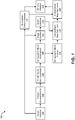
- Figure 1 is a block diagram of a method 100 illustrating components for producing a 3D face model. Each component may be implemented in hardware or software. For example, Figure 1 may be implemented on an electronic device (not shown). Examples of electronic devices include laptop or desktop computers, cellular phones, smart phones, wireless devices, e-readers, tablet devices, gaming systems, etc. Some of these devices may operate in accordance with one or more industry standards.
- Components in Figure 1 include an image receiver 102, a feature detector/matcher 104, a fundamental matrix estimator 106, a homographic matrix decomposer 108, an image rectifier 110, a depth estimator 112 and a 3D face modeler 114.
- Figure 1 also illustrates a homographic matrix inverter 116, an inverse depth map calculator 118, an inverse depth map normalizer 120 and a symmetrical feature detector 122.
- the components may be implemented on a single device or may be implemented on multiple devices. Each of these components will be discussed below in greater detail.
- the image receiver 102 may receive a set of two images (e.g., raw data) of a subject's face.
- the two images may be different perspectives relative to a face. In other words, the images may be such that the pixels in the two images are different vertically and horizontally.
- the image receiver 102 may be a single camera that takes two pictures. The first picture and the second picture may be taken at the same horizontal level, but the camera may be slightly moved or rotated left or right along a horizontal axis, thus producing slightly different images.
- the image receiver 102 may be a module that receives image input from an exterior device.
- the image receiver 102 may be implemented on an electronic device and receive an image taken by a camera phone or tablet device.
- the image receiver 102 may be located on the same electronic device that captures the set of images.
- the feature detector/matcher 104 may correlate the pixels of the first image with corresponding pixels of the second image. For instance, the feature detector/matcher 104 may detect facial features such as eyes, nose, mouth, etc., in each of the two images and match pixels from one feature in the first image to corresponding pixels of the same feature in the second image.
- the fundamental matrix estimator 106 may generate a fundamental matrix (H).
- a fundamental matrix may be a 3x3 matrix that relates to corresponding points in stereo images, e.g., the set of two images.
- the fundamental matrix may be estimated based on a number of matched features, points or pixels between the two images.
- a fundamental matrix may be estimated based on at least seven corresponding points, however, more or fewer corresponding points may be employed in estimating a fundamental matrix.
- a matrix estimator may generate another type of matrix from two images in which pixels are aligned vertically and differ horizontally.
- another type of matrix that is generated from two stereo images, other than a fundamental matrix may be used.
- the homographic matrix decomposer 108 may decompose one or more homographic (i.e., projective transformation) matrices from a fundamental matrix, such as a 3x3 homographic matrix, for example.
- a homographic matrix may provide rotation and translation information of a camera between two images.
- a pair of homographic matrices such as a first homographic matrix ( P L ) and a second homographic matrix ( P R ), may be decomposed from a fundamental matrix.
- the first homographic matrix may correspond to the first image and the second homographic matrix may correspond to the second image.
- the image rectifier 110 may rectify the two images by projecting the two images onto a common image plane. For example, the image rectifier 110 may apply the first homographic matrix to the first image and the second homographic matrix to the second image.
- the image rectifier 110 may produce rectified images (e.g., a first rectified image and a second rectified image).
- the image rectifier 110 projects stereo images onto a common image plane parallel to a line between optical centers in such a way that the corresponding points have the same row coordinates. In this manner, the problem associated with 2D stereo correspondence is reduced to a one dimensional (1D) problem.
- the depth estimator 112 may determine a depth map.
- a depth map may be an image or image channel that includes information relating to the distance of the surfaces of scene objects from a viewpoint, such as a camera.
- a depth map may provide depth values indicating the differences in depths between two rectified images.
- the depth estimator 112 may generate a depth map from a set of two rectified images.
- the 3D face modeler 114 may generate a 3D face model based on a depth map and one of the two images. For example, the 3D face modeler 114 may align detected features in an image with a depth map. In some configurations, the 3D face modeler 114 may employ an inverse depth map in generating a 3D face model.
- the homographic matrix inverter 116 may invert a homographic matrix.
- the homographic matrix inverter 116 may inverse a homographic matrix to obtain an inverted homographic matrix, such as a 3x3 inverted homographic matrix, for example.
- the homographic matrix inverter 116 may obtain an inverted first homographic matrix ( P L - 1 ) and an inverted second homographic matrix ( P R - 1 ).
- the inverse depth map calculator 118 may calculate or map an inverse depth map.
- the inverse depth map calculator 118 may map a depth map to an inverted homographic matrix to obtain an inverse depth map.
- An inverse depth map may correct for some distortions in the depth map caused by image rectification.
- the inverse depth map normalizer 120 may adjust and normalize an inverse depth map.
- the normalizations may include tilting, rotating, scaling, etc., an inverse depth map.
- the inverse depth map normalizer 120 may detect distortions in an inverse depth map and may perform adjustments accordingly.
- the inverse depth map normalizer 120 may adjust a subset of pixels in the inverse depth map.
- the inverse depth map normalizer 120 may normalize a non-inverted depth map. In other words, the inverse depth map normalizer 120 may normalize the depth map 242 directly.
- the symmetrical feature detector 122 may detect symmetrical features in an image, such as a human face.
- the symmetrical feature detector 122 may detect symmetrical features such as eyes, ears, lips, a nose, forehead areas, cheeks, glasses, eyebrows, etc.
- the components illustrated in Figure 1 may produce a 3D face model. For example, given two stereo images of a face, a depth map may be estimated and the background part of the depth map can be set as the flat plane. With a known depth value, the 3D coordinates of the face points may be calculated and the 3D face may be reconstructed as a 3D face model.
- the image receiver 102 may receive a set of images.
- the set of images may include a first image and a second image, a left image and a right image, a top image and a bottom image, two stereo images, etc.
- the two images in the set of images may include corresponding pixels that are aligned vertically, but differ horizontally. In some configurations, the pixels between the two images may be aligned horizontally, but not vertically.
- the image receiver 102 may provide the set of images to the feature detector/matcher 104.
- the image receiver 102 may send the images over a wired connection, wirelessly or via a storage medium.
- the feature detector/matcher 104 may identify corresponding features in the two images and may match the corresponding images together.
- An illustration of feature matching is shown in Figure 2 , described below.
- the feature detector/matcher 104 may provide correlated and matched images to the fundamental matrix estimator 106. Once a certain number of pixels have been matched, the feature detector/matcher 104 may provide this data to the fundamental matrix estimator 106.
- the fundamental matrix estimator 106 may estimate a fundamental matrix (H) based on the correlated images.
- the fundamental matrix may then be decomposed by the homographic matrix decomposer 108 to obtain two homographic matrices ( P L and P R ).
- the projective transformation matrices P L and P R for rectifying stereo images may be computed based on the fundamental matrix H.
- the image rectifier 110 may use the homographic matrix matrices P L and P R to rectify the first image and second image.
- the first homographic matrix P L may be mapped to a left image to produce a first rectified image
- the second homographic matrix P R may be mapped to a right image to produce a second rectified image.
- image rectification includes detecting and matching a set of corresponding points between the two images by the feature detector/matcher 104.
- X L and X R may each represent a 2D point that can be written as a 3D column vector in a [ x, y, 1] format.
- T may represent a matrix transpose.
- P L and P R are 3x3 matrices decomposed from a 3x3 fundamental matrix H by the homographic matrix decomposer 108.
- the image rectifier 110 applies 2D projective transformations on the two images.
- the pair of homographic matrices P L and P R is not unique because the two stereo-rectified images are stereo-rectified under a common rotation.
- the pair of homographic matrices P L and P R share a common rotation, based on the difference between the two images, rotated around a common baseline.
- undesirable distortion to the rectified images, specifically skewness and aspect/scale distortions may be introduced. An illustration of this distortion is shown and described below in Figure 2 .
- the two rectified images may be used by the depth estimator 112 to determine a depth map.
- a depth reconstruction may be determined.
- the rectified images are distorted, the depth map may be similarly distorted.
- image rectification causes undesirable distortions in the depth map, which may lead to a distorted 3D face model if not corrected.
- an inverse depth map may be generated by the inverse depth map calculator 118.
- the inverse depth map calculator 118 may obtain a depth map from the depth estimator 112 and an inverted homographic matrix from the homographic matrix inverter 116.
- the homographic matrix inverter 116 may invert the homographic matrix obtained from the homographic matrix decomposer 108 as described above.
- Inverting the depth map may partially correct distortions in the depth map caused by the image rectification process. For example, skewness and aspect/scale distortions may be corrected.
- normalizations to the depth map/ inverse depth map may be performed by the inverse depth map normalizer 120. Normalization may correct the inverse depth map to prevent the 3D face model from being improperly tilted, rotated and/or scaled.
- the inverse depth map normalizer 120 may receive input from the symmetrical feature detector 122.
- the symmetrical feature detector 122 may send detected symmetrical features and patterns to the inverse depth map normalizer 120.
- the inverse depth map normalizer 120 may use the detected symmetrical features to perform adjustments to ensure that the detected symmetrical features are correctly proportioned. Additional detail regarding image normalization is discussed in greater detail below.
- the 3D face modeler 114 may generate a 3D face model.
- the 3D face modeler 114 may map one of the original images to the inverse depth map, applying the detected features sent from the symmetrical feature detector 122 with corresponding points on the inverse depth map.
- the systems and methods presented herein it may be beneficial to invert the depth map and modify the inverse depth map based on face specific characteristics to reduce undesirable distortions during image rectification.
- existing approaches as descried previously, cause image distortion in the image rectification process and often require substantial user interaction.
- the systems and methods presented herein improve existing methods by inverting the depth map to partially account for distortion introduced in the image rectification process. Further corrections are applied by modifying and normalizing the inverse depth map based on face specific characteristics to improve the quality of the 3D face model.
- the systems and methods presented herein require minimal user interaction.
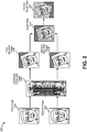
- Figure 2 illustrates a process 200 for producing an inverse depth map 242.
- the process 200 may be implemented in hardware or software.
- the process 200 may be implemented on an electronic device.
- the process 200 may correspond to the components described in connection with Figure 1 .
- Figure 2 illustrates a first image 230 and a second image 232.
- the first image 230 and the second image 232 may make up a set of stereo images.
- the two images may be of a single face taken from different viewpoints.
- an object other than a face may be used.
- more than two images may be employed.
- any number of images, where the vertical pixels are all aligned, may be used.
- the images may be provided to an image receiver 102.
- the raw, uncalibrated stereo images may be rectified.
- the first image 230 may first be correlated with the second image 232 resulting in a combined correlated image 234.
- a feature detector/matcher 104 may detect and match the first image 230 and the second image 232.
- a fundamental matrix estimator 106 may calculate a fundamental matrix based on linear projections of the matched points, as shown in the combined correlated image 234.
- the first image 230 and the second image 232 may be used via the combined correlated image 234 to produce a first rectified image 236 and a second rectified image 238.
- an image rectifier 110 may perform part of the image rectification process as described above.
- the first rectified image 236 and the second rectified image 238 may be distorted during the image rectification process, as shown in Figure 2 .
- a depth map 240 may be determined from the first rectified image 236 and the second rectified image 238. For instance, a depth estimator 112 may generate the depth map 240. The depth map 240 may be distorted as a result of the first rectified image 236 and the second rectified image 238 being distorted.
- an inverse depth map 242 may be calculated.
- an inverse depth map calculator 118 may calculate an inverse depth map 242.
- the inverse depth map 242 may be calculated by applying an inverted homographic matrix (e.g., P L -1 or P R - 1 ) to the depth map 240.
- an inverted homographic matrix e.g., P L -1 or P R - 1
- the inverse depth map 242 may correct distortions such as skewness in the depth map 240 caused by image rectification.
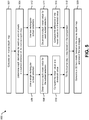
- Figure 3 is a flow diagram illustrating a method 300 for producing a 3D face model.
- the method 300 may be implemented in hardware or software.
- the method 300 may be implemented on an electronic device.
- An electronic device may obtain 302 two images, such as a first image 230 and a second image 232.
- the two images may be two stereo images received by an image receiver 102.
- the electronic device may determine 304 a fundamental matrix from the first image 230 and the second image 232.
- the fundamental matrix ( H ) may be a 3x3 matrix that tracks corresponding points in the two stereo images.
- the fundamental matrix may be generated by a fundamental matrix estimator 106 based on a combined correlated image 234.
- the electronic device may decompose 306 a first matrix corresponding to the first image 230 from the fundamental matrix.
- the electronic device may also decompose 306 a second matrix corresponding to the second image 232 from the fundamental matrix.
- the first matrix and the second matrix may be homographic matrices P L and P R , respectively, as described above.
- the first matrix and the second matrix may be P R and P L , respectively, or some other matrices.
- the first and second matrices may be decomposed from a homographic matrix decomposer 108.
- the electronic device may apply 308 the first matrix to the first image 230 to obtain a first rectified image 236.
- the electronic device may apply 308 the second matrix to the second image 232 to obtain a second rectified image 238.
- an image rectifier 110 may map or project the first matrix to the first image 230 to produce a first rectified image 236.
- the second rectified image 238 may be generated similarly. Distortions may be introduced during image rectification.
- the electronic device may determine 310 a depth map 240 from the first rectified image 236 and the second rectified image 238.
- the depth map 240 may be determined by a depth estimator 112. If the first rectified image 236 and the second rectified image 238 are distorted and skewed, then the depth map 240 will likely also be distorted and skewed.
- the depth map 240 may provide depth values indicating the differences in depths based on the first rectified image 236 and the second rectified image 238.
- the electronic device may calculate 312 an inverse depth map 242.
- the inverse depth map 242 may be calculated by inverting the first matrix (or the second matrix) and applying the inverted matrix to the depth map 240.
- an inverse depth map calculator 118 may perform these calculations.
- the inverted first matrix or inverted second matrix may be an inverted homographic matrix such as P L - 1 or P R -1 .
- a homographic matrix inverter 116 may provide the inverted first matrix or the inverted second matrix to the inverse depth map calculator 118 to obtain the inverse depth map 242.
- the electronic device may normalize 314 the inverse depth map 242 to correct for distortions in the depth map caused by image rectification.
- An inverse depth map normalizer 120 may adjust for distortions, for example. Additional detail regarding normalization will be described in greater detail below.
- the electronic device may generate 316 a 3D face model based on the inverse depth map 242 and one of the two images (e.g., the first image 230 or the second image 232). For instance, the 3D face modeler 114 may map one of the original images to the inverse depth map 242, which has been normalized. In generating the 3D face model, detected features from a symmetrical feature detector 122 may be mapped to corresponding points on the inverse depth map 242.
- the 3D face model does not include at least some of the distortions caused by image rectification because of the corrections performed by this method 300.
- While calculating an inverse depth map may correct for some distortion, other distortions, such as skewness, scaling and rotating distortions, may still affect the inverse depth map. These distortions may be caused by depth dimension distortion created during image rectification. For example, the left eye may be distorted from the rectification process and the left eye may have a larger depth value than the right eye. Normalization may correct distortions not corrected by creating an inverse depth map.
- face characteristics may be used. For example, left and right symmetrical features may be considered. As another example, tilting may be adjusted based on forehead and mouth areas. Scaling and rotation may also be adjusted based on symmetrical facial features, such as eyes, ears, lips, a nose, forehead areas, cheeks, glasses, eyebrows, etc. Figures 4-9 will describe various normalization processes in greater detail, such as tilting, scaling and rotating.
- FIG. 4 illustrates two tilted images.
- the tilted images may be based on the inverse depth map 242. Over tilt in the tilted images may be corrected for by comparing different depth values in various parts of the inverse depth map 242, as will be described below. Adjusting and refining the tilting of the inverse depth map 242 may be one method of normalizing the inverse depth map 242.
- the two tilted images in Figure 4 may include a first tilted image 444 and a second tilted image 454.
- a first ellipse 452 may be modeled to match the perimeter of the face in the first tilted image 444.
- the first ellipse 452 may include a first major axis ( a ) 448 and a first minor axis ( b ) 450 and may help in detecting distortions, such as over tilt in the first tilted image 444.
- over tilt may be detected by employing a first subset selection window 446. Over tilt may indicate that the image is tilted in either direction beyond an acceptable amount. In other words, an over tilted image may be tilted too far forward or tilted too far back about the first minor axis ( b ) 450.
- the first subset selection window 446 may be rectangular; however, other shapes may be employed. In one configuration, the first subset selection window 446 may have a height of a / 2 and a width of b / 3 . Other dimensions may be employed. In some configurations, the first subset selection window 446 may be co-centered with the first ellipse 452. In some configurations, the first subset selection window 446 may be centered with the nose area of the face on the first tilted image 444.
- the second tilted image 454 may similarly include a second ellipse 462 that includes a second major axis ( a ) 458 and a second minor axis ( b ) 460.
- the second ellipse 462 may be modeled to correspond to the face in the second tilted image 454.
- the second tilted image 454 may also include a second subset selection 456 and a third subset selection 466.
- the height and width of the second subset selection 456 and the third subset selection 466 may be equal; however, in some configurations, they may vary from one another.
- the second subset selection 456 and the third subset selection 466 may have a height of a / 4 and width of b / 3 .
- the second subset selection 456 and the third subset selection 466 may each be rectangular, or may be another type of shape, such as an ellipse. Further, the second subset selection 456 and the third subset selection 466 may be different shapes.
- the second subset selection 456 may be positioned over the forehead area and the third subset selection 466 may be located over the mouth area of the second tilted image 454.
- the forehead and the mouth of a subject's face are located in the same plane.
- the second subset selection 456 and the third subset selection 466 may be compared to determine the tilt angle.
- Determining tilt angle based on the first subset selection 446 or from the comparison of the second subset selection 456 and the third subset selection 466 is discussed below in Figures 5 and 6 .
- the image foreground and background should be considered so that adjustments may be focused on a subject's face and not the background. In addition, distinguishing between the foreground and the background allows for smoothing between the two surfaces.
- this may be performed by calculating a mean value of the face depth f m .
- the mean value of the face depth may be used to set the background depth d , which should be a flat plane behind the 3D face model.
- the background depth should be less than the mean face depth, however, the difference should not vary significantly. If d ⁇ w * f m , the image depth may be adjusted.
- w is a coefficient to control a threshold so as to prevent the face depth from being adjusted when the image depth is being adjusted. In this way, the background and the face boundary may be merged smoothly so that there is no strong blur on the boundary.
- Figure 5 is a flow diagram illustrating another method 500 producing a 3D face model.
- the method 500 may be implemented in hardware or software.
- the method 500 may be implemented on an electronic device.
- the electronic device may calculate 502 an inverse depth map 242.
- the electronic device may determine 504 depth derivatives for each column of pixels in a subset selection of the inverse depth map 242.
- the subset selection may be a first subset selection 446, a second subset selection 456 or a third subset selection 466.
- the depth derivative may be computed for each vertical column in a subset selection.
- each vertical column may be computed from the top to the bottom for each subset selection.
- the electronic device may use 506 a single rectangular subset selection (e.g., the first subset selection 446).
- the electronic device may determine 508 a mean value ( m ) for the subset selection, i.e., for all depth derivatives in the single subset selection. In other words, each depth derivative may be averaged to calculate m.
- the electronic device may compare 510 the mean value to a threshold value ( t 1 ). If
- the electronic device may use 512 use two rectangular subset selections (e.g., the second subset selection 456 and the third subset selection 466).
- the two rectangular subset selections may represent a first subset selection area and a second subset selection area.
- the electronic device may determine 514 a mean value ( m ) for each subset selection. For example, the electronic device may determine 514 a first mean value ( m 1 ) for the first subset selection area and a mean value ( m 2 ) for the second subset selection area.
- the electronic device may compare 516 the difference between the first area mean value and the second area mean value to a threshold value ( t 2 ). For example,
- the threshold values i.e., t 1 and t 2 ) may be based on empirical data, user preference, historical values, etc.
- the electronic device may generate 520 a 3D face model based on the inverse depth map 242 and one of the two images. This may be performed as described above.
- Figure 6 is a flow diagram illustrating a method 600 for tilting an inverse depth map 242.
- the method 600 may be implemented in hardware or software.
- the method 600 may be implemented on an electronic device.
- This method 600 may be one example of normalizing an inverse depth map 242.
- the electronic device may initiate 602 tilt adjustments.
- the electronic device may perform 604 face detection and eye detection.
- face detection and eye detection may be performed on an inverse depth map 242 or one of the raw input images.
- performing 604 face detection and eye detection may be performed by a symmetrical feature detector 122.
- the electronic device may model 606 the face as an ellipse with major axis a and minor axis b.
- the ellipse may be like the first ellipse 452 or the second ellipse 462 described above in connection with Figure 4 .
- the electronic device may set 608 one rectangle, co-centered with the ellipse.
- the rectangle may have a width of b /3 and a height of a /2.
- the rectangle may be like the first subset selection 446 of Figure 4 .
- the electronic device may calculate 610 an average derivative value ( m ) along the vertical direction of the face.
- the electronic device may compare 612 if
- ⁇ t 1 .
- the electronic device may set 616 two rectangles, each with width b /3 and height a /2, centered at the forehead and mouth areas in the ellipse.
- the two rectangles may be like the second subset selection 456 and the third subset selection 466 of Figure 4 .
- the electronic device may calculate 618 an average depth value ( m 1 and m 2 ) for each of the two rectangles. This may be performed as described in connection with Figure 5 above.
- the electronic device may compare 620 if
- Figure 7 illustrates a process 700 for normalizing an inverse depth map 742.
- the process 700 may be implemented in hardware or software.
- the process 700 may be implemented on an electronic device.
- the process 700 may correspond to the components described in connection with Figure 1 .
- Figure 7 illustrates an inverse depth map 742, which may correspond to the inverse depth map 242 described above.
- Figure 7 also illustrates a detected image 774, a normalized inverse depth map 778 and a 3D face model 780.
- the inverse depth map 742 may have been previously adjusted and corrected for over tilt. In other approaches, tilting may be adjusted later on.
- the positions of the face area and the eyes may be detected, as shown in a detected symmetrical feature 776.
- the inverse depth map 742 may be adjusted proportionally to make the left and right sides on the same depth level.
- the detected image 774 may include a detected symmetrical feature 776, such as a pair of eyes.
- Other symmetrical features may include ears, lips, a nose, forehead areas, cheeks, glasses, eyebrows, etc.
- the detected image 774 may be generated by a symmetrical feature detector 122.
- the detected image 774 may employ a first image 230 or a second image 232 from the set of stereo images.
- the detected image 774 may be a depth map 240 or an inverse depth map 742.
- the inverse depth map 742 and the detected image 774 may be used in obtaining the normalized inverse depth map 778.
- an inverse depth map normalizer 120 may generate a normalized inverse depth map 778 using the inverse depth map 742 and/or the detected image 774.
- the 3D face model 780 may be generated based on the inverse depth map 742 and one of the two images (e.g., the first image 230 or the second image 232). For example, a 3D face modeler 114 may generate a 3D face model 780 to align detected symmetrical features 776 in an image with the inverse depth map 742.
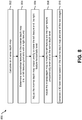
- Figure 8 is a flow diagram illustrating another method 800 for producing a 3D face model 780.
- the method 800 may be implemented in hardware or software.
- the method 800 may be implemented on an electronic device.
- An electronic device may calculate 802 an inverse depth map 742, as described above.
- the electronic device may determine 804 symmetrical features in the inverse depth map 742. For example, a left feature symmetric with a right feature may be determined 804. The left feature and the right feature may be included as a detected symmetrical feature 776.
- Symmetrical features may be matched by a symmetrical feature detector 122. Symmetrical features may be based on known facial features or calculated from symmetrical-like features on corresponding sides of an image.
- the left feature and the right feature may be, for example, a pair of eyes.
- the pair of eyes may not be proportional to each other.
- the left eye in the inverse depth map 742 may have a larger depth value than the right eye.
- the electronic device may adjust 806 the inverse depth map 742 proportionally to make the left feature and the right feature horizontally level.
- inverse depth map 742 may be rotated about an axis running perpendicular to the image to align the left feature and the right feature until they are horizontally level. This is explained in greater detail below in connection with Figure 9 .
- the electronic device may adjust 808 the inverse depth map 742 to make the left feature and the right feature proportionally even and at the same depth level.
- the inverse depth map 742 may be rotated about a vertical axis until the left feature and the right feature are even.
- the pixels in one or both features may be adjusted until the left feature and the right feature are proportionally even. For instance, given a set of eyes where the left eye is larger than the right eye, the depth level of the left eye may be decreased and/or the depth level of the right eye may be increased. In another instance, the size or scale of the left eye may be decreased and/or the size or scale of the right eye may be increased. A combination of adjustments may be performed to make the left feature and the right feature proportionally even and at the same depth level. In this manner the inverse depth map 742 may be adjusted until the left feature and the right feature are on the same plane. The electronic device may generate 810 a 3D face model 780 based on the inverse depth map 742 and one of the two images. This may be performed as described above.
- Figure 9 is a flow diagram illustrating a method 900 for normalizing an inverse depth map 742.
- the method 900 may be implemented in hardware or software.
- the method 900 may be implemented on an electronic device.
- this method 900 may be employed in connection with method 600 described in connection with Figure 6 for tilting an inverse depth map 742.
- the electronic device may initiate 902 rotation adjustments.
- the electronic device may perform 904 face detection and eye detection.
- face detection and eye detection may be performed on an inverse depth map 742 or one of the raw input images.
- performing 904 face detection and eye detection may be performed by a symmetrical feature detector 122.
- the electronic device may model 906 the face as an ellipse with major axis a and minor axis b .
- the ellipse may be similar to the first ellipse 452 or the second ellipse 462 described above in connection with Figure 4 .
- the electronic device may set 908 two rectangles, one centered at the left eye and one centered at the right eye.
- Each rectangle may have a width of b /4 and a height of a /8.
- Other dimensions and shapes may be employed.
- the two rectangles may each have a width of b /3 and a height of a /2.
- the two rectangles may have different dimensions from each other.
- shapes other than rectangles may be employed.
- the two rectangles may be like the second subset selection 456 and the third subset selection 466 of Figure 4 , but positioned over the eyes and having different dimensions.
- the electronic device may calculate 910 the average depth value ( m 1 and m 2 ) for the two rectangles. This may be performed as described in connection with Figure 5 above.
- the electronic device may compare 912 if
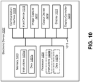
- Figure 10 illustrates certain components that may be included within an electronic device 1001.
- One or more of the electronic devices described above may be configured similarly to the electronic device 1001 that is shown in Figure 10 .
- the electronic device 1001 includes a processor 1009.
- the processor 1009 may be a general purpose single- or multi-chip microprocessor (e.g., an ARM), a special purpose microprocessor (e.g., a digital signal processor (DSP)), a microcontroller, a programmable gate array, etc.
- the processor 1009 may be referred to as a central processing unit (CPU). Although just a single processor 1009 is shown in the electronic device 1001 of Figure 10 , in an alternative configuration, a combination of processors (e.g., an ARM and DSP) could be used.
- the electronic device 1001 also includes memory 1003 in electronic communication with the processor 1009 (i.e., the processor 1009 can read information from and/or write information to the memory 1003).
- the memory 1003 may be any electronic component capable of storing electronic information.
- the memory 1003 may be random access memory (RAM), read-only memory (ROM), magnetic disk storage media, optical storage media, flash memory devices in RAM, on-board memory included with the processor, programmable read-only memory (PROM), erasable programmable read-only memory (EPROM), electrically erasable PROM (EEPROM), registers, and so forth, including combinations thereof.
- RAM random access memory
- ROM read-only memory
- EPROM erasable programmable read-only memory
- EEPROM electrically erasable PROM
- Instructions 1005a and data 1007a may be stored in the memory 1003.
- the instructions 1005a may include one or more programs, routines, sub-routines, functions, procedures, code, etc.
- the instructions 1005a may include a single computer-readable statement or many computer-readable statements.
- the instructions 1005a may be executable by the processor 1009 to implement one or more of the methods 300, 500, 600, 800 and 900, described above. Executing the instructions 1005a may involve the use of the data 1007a that is stored in the memory 1003.
- Figure 10 shows some instructions 1005b and data 1007b being loaded into the processor 1009 (which may come from instructions 1005a and data 1007a).
- the electronic device 1001 may include one or more image capture components 1017 for capturing images.
- an image capture component 1017 may be a camera or a photo cell for capturing images, such as stereo images.
- the electronic device 1001 may also include one or more communication interfaces 1013 for communicating with other electronic devices.
- the communication interfaces 1013 may be based on wired communication technology, wireless communication technology, or both. Examples of different types of communication interfaces 1013 include a serial port, a parallel port, a Universal Serial Bus (USB), an Ethernet adapter, an IEEE 1394 bus interface, a small computer system interface (SCSI) bus interface, an infrared (IR) communication port, a Bluetooth wireless communication adapter, and so forth.
- the electronic device 1001 may also include one or more input devices 1015 and one or more output devices 1019.
- input devices 1015 include a keyboard, mouse, microphone, remote control device, button, joystick, trackball, touchpad, lightpen, etc.
- the electronic device 1001 may include one or more image capture components 1017 for capturing images.
- Examples of different kinds of output devices 1019 include a speaker, printer, 3D printer, etc.
- One specific type of output device 1019 which may be typically included in an electronic device 1001 is a display 1023.
- a display 1023 used with configurations disclosed herein may utilize any suitable image projection technology, such as a cathode ray tube (CRT), liquid crystal display (LCD), light-emitting diode (LED), gas plasma, electroluminescence, or the like.
- CTR cathode ray tube
- LCD liquid crystal display
- LED light-emitting diode
- gas plasma electroluminescence
- a display controller 1025 may also be provided for converting data stored in the memory 1003 into text, graphics and/or moving images (as appropriate) shown on the display 1023.
- the electronic device 1001 may also include a transmitter (not shown) and a receiver (not shown) to allow transmission and reception of signals between the electronic device 1001 and a remote location (e.g., another electronic device, a wireless communication device, etc.).
- the transmitter and receiver may be collectively referred to as a transceiver.
- An antenna (not shown) may be electrically coupled to the transceiver.
- the electronic device 1001 may also include (not shown) multiple transmitters, multiple receivers, multiple transceivers and/or multiple antenna.
- the various components of the electronic device 1001 may be coupled together by one or more buses, which may include a power bus, a control signal bus, a status signal bus, a data bus, etc.
- buses may include a power bus, a control signal bus, a status signal bus, a data bus, etc.
- the various buses are illustrated in Figure 10 as a bus system 1011.
- a circuit may be adapted to generate a three-dimensional face.
- a first section of the circuit may be adapted to calculate an inverse depth map based on a depth map and an inverted first matrix.
- the inverted first matrix may be generated from two images in which pixels are aligned vertically and differ horizontally.
- the same circuit, a different circuit, a section of a different circuit or a second section of the same circuit may be adapted to normalize the inverse depth map to correct for distortions in the depth map caused by image rectification.
- the same circuit, a different circuit, a section of a different circuit, or a third section of the same circuit may be adapted to generate a three-dimensional face model based on the inverse depth map and one of the two images.
- determining encompasses a wide variety of actions and, therefore, “determining” can include calculating, computing, processing, deriving, investigating, looking up (e.g., looking up in a table, a database or another data structure), ascertaining and the like. Also, “determining” can include receiving (e.g., receiving information), accessing (e.g., accessing data in a memory) and the like. Also, “determining” can include resolving, selecting, choosing, establishing and the like.
- processor should be interpreted broadly to encompass a general purpose processor, a central processing unit (CPU), a microprocessor, a digital signal processor (DSP), a controller, a microcontroller, a state machine and so forth. Under some circumstances, a “processor” may refer to an application specific integrated circuit (ASIC), a programmable logic device (PLD), a field programmable gate array (FPGA), etc.
- ASIC application specific integrated circuit
- PLD programmable logic device
- FPGA field programmable gate array
- processor may refer to a combination of processing devices, e.g., a combination of a DSP and a microprocessor, a plurality of microprocessors, one or more microprocessors in conjunction with a DSP core, or any other such configuration.
- memory should be interpreted broadly to encompass any electronic component capable of storing electronic information.
- the term memory may refer to various types of processor-readable media such as random access memory (RAM), read-only memory (ROM), non-volatile random access memory (NVRAM), programmable read-only memory (PROM), erasable programmable read-only memory (EPROM), electrically erasable PROM (EEPROM), flash memory, magnetic or optical data storage, registers, etc.
- RAM random access memory
- ROM read-only memory
- NVRAM non-volatile random access memory
- PROM programmable read-only memory
- EPROM erasable programmable read-only memory
- EEPROM electrically erasable PROM
- flash memory magnetic or optical data storage, registers, etc.
- instructions and “code” should be interpreted broadly to include any type of computer-readable statement(s).
- the terms “instructions” and “code” may refer to one or more programs, routines, sub-routines, functions, procedures, etc.
- “Instructions” and “code” may include a single computer-readable statement or many computer-readable statements.
- a computer-readable medium or “computer-program product” refers to any tangible non-transitory storage medium that can be accessed by a computer or a processor.
- a computer-readable medium may include RAM, ROM, EEPROM, CD-ROM or other optical disk storage, magnetic disk storage or other magnetic storage devices, or any other medium that can be used to carry or store desired program code in the form of instructions or data structures and that can be accessed by a computer.
- Disk and disc includes compact disc (CD), laser disc, optical disc, digital versatile disc (DVD), floppy disk and Blu-ray® disc where disks usually reproduce data magnetically, while discs reproduce data optically with lasers.
- the methods disclosed herein include one or more steps or actions for achieving the described method.
- the method steps and/or actions may be interchanged with one another without departing from the scope of the claims.
- the order and/or use of specific steps and/or actions may be modified without departing from the scope of the claims.
- modules and/or other appropriate means for performing the methods and techniques described herein can be downloaded and/or otherwise obtained by a device.
- a device For example, an electronic device may be coupled to a server to facilitate the transfer of means for performing the methods described herein.
- various methods described herein can be provided via a storage means (e.g., random access memory (RAM), read-only memory (ROM), a physical storage medium such as a compact disc (CD) or floppy disk, etc.), such that a device may obtain the various methods upon coupling or providing the storage means to the device.
- RAM random access memory
- ROM read-only memory
- CD compact disc
- floppy disk floppy disk
Landscapes
- Engineering & Computer Science (AREA)
- Physics & Mathematics (AREA)
- General Physics & Mathematics (AREA)
- Theoretical Computer Science (AREA)
- Computer Vision & Pattern Recognition (AREA)
- Computer Graphics (AREA)
- Image Processing (AREA)
- Image Analysis (AREA)
- Processing Or Creating Images (AREA)
- Image Generation (AREA)
Description
- The present disclosure relates generally to electronic devices. More specifically, the present disclosure relates to systems and methods for producing a three-dimensional (3D) face model.
- In the last several decades, the use of electronic devices has become common. In particular, advances in electronic technology have reduced the cost of increasingly complex and useful electronic devices. Cost reduction and consumer demand have proliferated the use of electronic devices such that they are practically ubiquitous in modern society. As the use of electronic devices has expanded, so has the demand for new and improved features of electronic devices. More specifically, electronic devices that perform new functions and/or that perform functions faster, more efficiently or with higher quality are often sought after.
- Some electronic devices (e.g., cameras, video camcorders, digital cameras, cellular phones, smart phones, computers, televisions, etc.) capture or utilize images. For example, a digital camera may capture a digital image.
- New and/or improved features of electronic devices are often sought for. As can be observed from this discussion, systems and methods that add new and/or improved features of electronic devices may be beneficial.
- The article by Maitre M et al "Symmetric multi-view stereo reconstruction from planar camera arrays" in IEEE Conference on Computer Vision and Pattern Recognition in 2008 is referred to.
-
-
Figure 1 is a block diagram illustrating components for producing a three-dimensional (3D) face model; -
Figure 2 illustrates a process for producing an inverse depth map; -
Figure 3 is a flow diagram illustrating a method for producing a 3D face model; -
Figure 4 illustrates two tilted images; -
Figure 5 is a flow diagram illustrating another method for producing a 3D face model; -
Figure 6 is a flow diagram illustrating a method for tilting an inverse depth map; -
Figure 7 illustrates a process for normalizing an inverse depth map; -
Figure 8 is a flow diagram illustrating another method for producing a 3D face model; -
Figure 9 is a flow diagram illustrating a method for normalizing an inverse depth map; and -
Figure 10 illustrates certain components that may be included within an electronic device. - The invention is defined in the claims to which reference is now directed.
- The two images may be different perspectives relative to a human face. Normalizing the inverse depth map may include normalizing a subset of pixels in the inverse depth map. Normalizing the inverse depth map may include one of rotating, tilting and scaling the inverse depth map.
- Tilting the inverse depth map may include determining depth derivatives for each column of pixels in a subset selection of the inverse depth map, determining a mean value of all the depth derivatives for the subset selection, comparing the mean value to a threshold value and tilting the inverse depth map based on the comparison. The subset selection may include a rectangular area. The subset selection may include a first area and a second area. Comparing the mean value to a threshold value may also include comparing a difference between the mean value of the first area and the mean value of the second area to a threshold value.
- Rotating the inverse depth map may include detecting symmetrical features in the inverse depth map, the symmetrical features having a left feature and a right feature, and adjusting the inverse depth map proportionally to make the left feature and the right feature horizontally level.
- Scaling the inverse depth map may include detecting symmetrical features in the inverse depth map, the symmetrical features having a left feature and a right feature, and adjusting the inverse depth map to make the left feature and the right feature proportionally even and at the same depth level.
- A three-dimensional (3D) face model can be used for different applications, such as virtual reality and face recognition. 3D models may be generated from a set of two-dimensional (2D) images. For example, a set of 2D pictures displaying an image of a face may be used to create a 3D rendering of the face. For instance, 3D face model reconstruction using two images captured by a phone may provide a low-cost solution compared with studio environments.
- In one known approach, a 3D face model is constructed from two stereo images. In this approach, camera calibration is not necessary. But this approach uses epipolar geometry to estimate the depth directly. To find the corresponding epipolar lines between two images, it requires face images to be taken in front of a white board. On the white board, a black rectangle must be included and is positioned such that the height of the target face fits within the black rectangle. In this approach, the images must be manually hand-coded for any extreme color on the four corners of the rectangle. Accordingly, this approach has limited applications and requires substantial user interaction.
- In other known stereo camera-based 3D face reconstruction approaches, the stereo camera hardware and camera require calibration. Camera calibration can be complex, costly and time consuming, and it may require substantial user interaction.
- In another known approach, a generic face model and several 2D face images are used to construct a 3D face. The facial features are matched and the generic face model is fitted to these feature points. The structure of the face depth is then computed. But this approach depends on the architecture of the generic face model,
facial feature detection, etc. This approach may not capture the subject's natural face. In other words, this approach may distort a subject's face in applying it to the general face model. - Similarly, in another known approach involving 3D face reconstruction with a single view camera, a face is reconstructed into a 3D structure using a single 2D image. This approach employs a database of the objects (e.g., face models) containing example patches. In this approach, the data sets used in practice do not guarantee the presence of objects sufficiently similar to the query for accurate reconstructions.
- Many current 3D image-generating methods, however, use an image rectification process that causes distortions to a subject's face when rendered as a 3D face model. Image rectification generally includes detection and matching of a set of corresponding points between a pair of 2D images. Under this approach, the rectified images are left skewed and distorted. In other approaches, manual modifications and corrections are required to eliminate distortion caused by image rectification.
- Therefore, the present systems and methods may provide improved methods and configurations for automatically producing a 3D face model from two 2D images, for example, taken by a single camera. In some configurations, an inverse matrix may be employed to automatically correct image distortion with minimal user interaction. In some configurations, rotating, tilting and scaling may correct image distortion. Systems and methods for 3D face generation and producing a 3D face model are explained in greater detail below.
-
Figure 1 is a block diagram of amethod 100 illustrating components for producing a 3D face model. Each component may be implemented in hardware or software. For example,Figure 1 may be implemented on an electronic device (not shown). Examples of electronic devices include laptop or desktop computers, cellular phones, smart phones, wireless devices, e-readers, tablet devices, gaming systems, etc. Some of these devices may operate in accordance with one or more industry standards. - Components in
Figure 1 include animage receiver 102, a feature detector/matcher 104, afundamental matrix estimator 106, ahomographic matrix decomposer 108, animage rectifier 110, adepth estimator 112 and a3D face modeler 114.Figure 1 also illustrates ahomographic matrix inverter 116, an inversedepth map calculator 118, an inversedepth map normalizer 120 and asymmetrical feature detector 122. The components may be implemented on a single device or may be implemented on multiple devices. Each of these components will be discussed below in greater detail. - The
image receiver 102 may receive a set of two images (e.g., raw data) of a subject's face. The two images may be different perspectives relative to a face. In other words, the images may be such that the pixels in the two images are different vertically and horizontally. In one configuration, theimage receiver 102 may be a single camera that takes two pictures. The first picture and the second picture may be taken at the same horizontal level, but the camera may be slightly moved or rotated left or right along a horizontal axis, thus producing slightly different images. - In another configuration, the
image receiver 102 may be a module that receives image input from an exterior device. For example, theimage receiver 102 may be implemented on an electronic device and receive an image taken by a camera phone or tablet device. In some configurations, theimage receiver 102 may be located on the same electronic device that captures the set of images. - The feature detector/
matcher 104 may correlate the pixels of the first image with corresponding pixels of the second image. For instance, the feature detector/matcher 104 may detect facial features such as eyes, nose, mouth, etc., in each of the two images and match pixels from one feature in the first image to corresponding pixels of the same feature in the second image. - The
fundamental matrix estimator 106 may generate a fundamental matrix (H). A fundamental matrix may be a 3x3 matrix that relates to corresponding points in stereo images, e.g., the set of two images. The fundamental matrix may be estimated based on a number of matched features, points or pixels between the two images. In general, a fundamental matrix may be estimated based on at least seven corresponding points, however, more or fewer corresponding points may be employed in estimating a fundamental matrix. - In some configurations, a matrix estimator may generate another type of matrix from two images in which pixels are aligned vertically and differ horizontally. In other words, another type of matrix that is generated from two stereo images, other than a fundamental matrix, may be used.
- The
homographic matrix decomposer 108 may decompose one or more homographic (i.e., projective transformation) matrices from a fundamental matrix, such as a 3x3 homographic matrix, for example. A homographic matrix may provide rotation and translation information of a camera between two images. A pair of homographic matrices, such as a first homographic matrix (PL ) and a second homographic matrix (PR ), may be decomposed from a fundamental matrix. The first homographic matrix may correspond to the first image and the second homographic matrix may correspond to the second image. - The
image rectifier 110 may rectify the two images by projecting the two images onto a common image plane. For example, theimage rectifier 110 may apply the first homographic matrix to the first image and the second homographic matrix to the second image. Theimage rectifier 110 may produce rectified images (e.g., a first rectified image and a second rectified image). In some configurations, theimage rectifier 110 projects stereo images onto a common image plane parallel to a line between optical centers in such a way that the corresponding points have the same row coordinates. In this manner, the problem associated with 2D stereo correspondence is reduced to a one dimensional (1D) problem. - The
depth estimator 112 may determine a depth map. A depth map may be an image or image channel that includes information relating to the distance of the surfaces of scene objects from a viewpoint, such as a camera. A depth map may provide depth values indicating the differences in depths between two rectified images. Thedepth estimator 112 may generate a depth map from a set of two rectified images. - The
3D face modeler 114 may generate a 3D face model based on a depth map and one of the two images. For example, the3D face modeler 114 may align detected features in an image with a depth map. In some configurations, the3D face modeler 114 may employ an inverse depth map in generating a 3D face model. - The
homographic matrix inverter 116 may invert a homographic matrix. Thehomographic matrix inverter 116 may inverse a homographic matrix to obtain an inverted homographic matrix, such as a 3x3 inverted homographic matrix, for example. Thehomographic matrix inverter 116 may obtain an inverted first homographic matrix (PL -1) and an inverted second homographic matrix (PR -1). - The inverse
depth map calculator 118 may calculate or map an inverse depth map. For example, the inversedepth map calculator 118 may map a depth map to an inverted homographic matrix to obtain an inverse depth map. An inverse depth map may correct for some distortions in the depth map caused by image rectification. - The inverse
depth map normalizer 120 may adjust and normalize an inverse depth map. The normalizations may include tilting, rotating, scaling, etc., an inverse depth map. For example, the inversedepth map normalizer 120 may detect distortions in an inverse depth map and may perform adjustments accordingly. In some configurations, the inversedepth map normalizer 120 may adjust a subset of pixels in the inverse depth map. In some configurations, the inversedepth map normalizer 120 may normalize a non-inverted depth map. In other words, the inversedepth map normalizer 120 may normalize the depth map 242 directly. - The
symmetrical feature detector 122 may detect symmetrical features in an image, such as a human face. For example, thesymmetrical feature detector 122 may detect symmetrical features such as eyes, ears, lips, a nose, forehead areas, cheeks, glasses, eyebrows, etc. - The components illustrated in
Figure 1 may produce a 3D face model. For example, given two stereo images of a face, a depth map may be estimated and the background part of the depth map can be set as the flat plane. With a known depth value, the 3D coordinates of the face points may be calculated and the 3D face may be reconstructed as a 3D face model. - In one approach, the
image receiver 102 may receive a set of images. The set of images may include a first image and a second image, a left image and a right image, a top image and a bottom image, two stereo images, etc. The two images in the set of images may include corresponding pixels that are aligned vertically, but differ horizontally. In some configurations, the pixels between the two images may be aligned horizontally, but not vertically. - The
image receiver 102 may provide the set of images to the feature detector/matcher 104. For example, theimage receiver 102 may send the images over a wired connection, wirelessly or via a storage medium. - The feature detector/
matcher 104 may identify corresponding features in the two images and may match the corresponding images together. An illustration of feature matching is shown inFigure 2 , described below. - The feature detector/
matcher 104 may provide correlated and matched images to thefundamental matrix estimator 106. Once a certain number of pixels have been matched, the feature detector/matcher 104 may provide this data to thefundamental matrix estimator 106. - The
fundamental matrix estimator 106 may estimate a fundamental matrix (H) based on the correlated images. The fundamental matrix may then be decomposed by thehomographic matrix decomposer 108 to obtain two homographic matrices (PL and PR ). In other words, the projective transformation matrices PL and PR for rectifying stereo images may be computed based on the fundamental matrix H. - The
image rectifier 110 may use the homographic matrix matrices PL and PR to rectify the first image and second image. For example, the first homographic matrix PL may be mapped to a left image to produce a first rectified image and the second homographic matrix PR may be mapped to a right image to produce a second rectified image. - An example of the image rectification process will now be given. In one configuration, image rectification includes detecting and matching a set of corresponding points between the two images by the feature detector/
matcher 104. The correctly matched points are used to compute the fundamental matrix H by thefundamental matrix estimator 106 such that XR T HXL=0, where XL is a point (e.g., pixel) in a left image and XR is a corresponding point (e.g., pixel) in a right image. In other words, XL and XR may each represent a 2D point that can be written as a 3D column vector in a [x, y, 1] format. T may represent a matrix transpose. Thus, when the 3D column vector is transposed, the result is a 3D row vector, written as [x, y, 1] (e.g., column vector [x, y, 1] = row vector [x, y, 1]). - In this configuration, PL and PR are 3x3 matrices decomposed from a 3x3 fundamental matrix H by the
homographic matrix decomposer 108. Given PL and PR , theimage rectifier 110 applies 2D projective transformations on the two images. Here, rectifying the images changes each image pixel (X) from a raw data pixel, written as X=[x, y, 1] T , to a rectified image pixel, written as XL'=PL XL or XR=PR XR. Further, in this configuration, there is no need for camera intrinsic and extrinsic parameters. - However, in this configuration, the pair of homographic matrices PL and PR is not unique because the two stereo-rectified images are stereo-rectified under a common rotation. In other words, the pair of homographic matrices PL and PR share a common rotation, based on the difference between the two images, rotated around a common baseline. As a result, undesirable distortion to the rectified images, specifically skewness and aspect/scale distortions may be introduced. An illustration of this distortion is shown and described below in
Figure 2 . - Once the set of images are rectified, the two rectified images may be used by the
depth estimator 112 to determine a depth map. In other words, given the reconstructed stereo images, a depth reconstruction may be determined. But if the rectified images are distorted, the depth map may be similarly distorted. Thus, under this approach, image rectification causes undesirable distortions in the depth map, which may lead to a distorted 3D face model if not corrected. - To correct for the distortion in the depth map caused by image rectification, an inverse depth map may be generated by the inverse
depth map calculator 118. The inversedepth map calculator 118 may obtain a depth map from thedepth estimator 112 and an inverted homographic matrix from thehomographic matrix inverter 116. Thehomographic matrix inverter 116 may invert the homographic matrix obtained from thehomographic matrix decomposer 108 as described above. - The inverse
depth map calculator 118 may map the depth map to the inverted homographic matrix to produce an inverse depth map. For example, given a depth map (M) estimated from the two rectified stereo images, M may be inversely mapped to one of original images by applying an inverse matrix such as PL or PR. In this example, a pixel (m) in M, written as m=[x, y, z]T, will become a new pixel (m'), written as m'= PL -1 m. Thus, after inverse mapping, m'=[x', y', z'] as part of an inverse depth map (M'). In the above examples, z represents a pixel value in the depth map and z' represents a pixel value in the inverse depth map. - Inverting the depth map may partially correct distortions in the depth map caused by the image rectification process. For example, skewness and aspect/scale distortions may be corrected. In addition to partially correcting for distortions in the depth map caused by the image rectification process, normalizations to the depth map/ inverse depth map may be performed by the inverse
depth map normalizer 120. Normalization may correct the inverse depth map to prevent the 3D face model from being improperly tilted, rotated and/or scaled. For example, the normalized pixel may be written as [xa, ya] where xa=x'/z' and ya=y'/z'. Accordingly, after normalization, the depth map may be on the same plane as the original image. Further, distortion on the 2D plane may be removed. - The inverse
depth map normalizer 120 may receive input from thesymmetrical feature detector 122. For example, thesymmetrical feature detector 122 may send detected symmetrical features and patterns to the inversedepth map normalizer 120. The inversedepth map normalizer 120 may use the detected symmetrical features to perform adjustments to ensure that the detected symmetrical features are correctly proportioned. Additional detail regarding image normalization is discussed in greater detail below. - Once the inverse depth map is corrected and normalized, the
3D face modeler 114 may generate a 3D face model. The3D face modeler 114 may map one of the original images to the inverse depth map, applying the detected features sent from thesymmetrical feature detector 122 with corresponding points on the inverse depth map. - According to the systems and methods presented herein, it may be beneficial to invert the depth map and modify the inverse depth map based on face specific characteristics to reduce undesirable distortions during image rectification. Specifically, existing approaches, as descried previously, cause image distortion in the image rectification process and often require substantial user interaction. The systems and methods presented herein improve existing methods by inverting the depth map to partially account for distortion introduced in the image rectification process. Further corrections are applied by modifying and normalizing the inverse depth map based on face specific characteristics to improve the quality of the 3D face model. Moreover, the systems and methods presented herein require minimal user interaction.
-
Figure 2 illustrates aprocess 200 for producing an inverse depth map 242. Theprocess 200 may be implemented in hardware or software. For example, theprocess 200 may be implemented on an electronic device. In some configurations, theprocess 200 may correspond to the components described in connection withFigure 1 . -
Figure 2 illustrates afirst image 230 and asecond image 232. Thefirst image 230 and thesecond image 232 may make up a set of stereo images. For example, the two images may be of a single face taken from different viewpoints. In some configurations, an object other than a face may be used. - In some configurations, more than two images may be employed. For example, any number of images, where the vertical pixels are all aligned, may be used. The images may be provided to an
image receiver 102. - Given the two images taken of a human face from different viewpoints (e.g., the
first image 230 and the second image 232), the raw, uncalibrated stereo images may be rectified. In rectifying the two images, thefirst image 230 may first be correlated with thesecond image 232 resulting in a combined correlatedimage 234. For instance, a feature detector/matcher 104 may detect and match thefirst image 230 and thesecond image 232. Then, afundamental matrix estimator 106 may calculate a fundamental matrix based on linear projections of the matched points, as shown in the combined correlatedimage 234. - The
first image 230 and thesecond image 232 may be used via the combined correlatedimage 234 to produce a first rectifiedimage 236 and a second rectifiedimage 238. For example, animage rectifier 110 may perform part of the image rectification process as described above. The first rectifiedimage 236 and the second rectifiedimage 238 may be distorted during the image rectification process, as shown inFigure 2 . - A
depth map 240 may be determined from the first rectifiedimage 236 and the second rectifiedimage 238. For instance, adepth estimator 112 may generate thedepth map 240. Thedepth map 240 may be distorted as a result of the first rectifiedimage 236 and the second rectifiedimage 238 being distorted. - To correct for this distortion, an inverse depth map 242 may be calculated. For example, an inverse
depth map calculator 118 may calculate an inverse depth map 242. The inverse depth map 242 may be calculated by applying an inverted homographic matrix (e.g., PL -1 or PR -1) to thedepth map 240. As illustrated inFigure 2 , the inverse depth map 242 may correct distortions such as skewness in thedepth map 240 caused by image rectification. -
Figure 3 is a flow diagram illustrating amethod 300 for producing a 3D face model. Themethod 300 may be implemented in hardware or software. For example, themethod 300 may be implemented on an electronic device. An electronic device may obtain 302 two images, such as afirst image 230 and asecond image 232. The two images may be two stereo images received by animage receiver 102. - The electronic device may determine 304 a fundamental matrix from the
first image 230 and thesecond image 232. The fundamental matrix (H) may be a 3x3 matrix that tracks corresponding points in the two stereo images. The fundamental matrix may be generated by afundamental matrix estimator 106 based on a combined correlatedimage 234. - The electronic device may decompose 306 a first matrix corresponding to the
first image 230 from the fundamental matrix. The electronic device may also decompose 306 a second matrix corresponding to thesecond image 232 from the fundamental matrix. For example, the first matrix and the second matrix may be homographic matrices PL and PR, respectively, as described above. In some configurations, the first matrix and the second matrix may be PR and PL, respectively, or some other matrices. In some configurations, the first and second matrices may be decomposed from ahomographic matrix decomposer 108. - The electronic device may apply 308 the first matrix to the
first image 230 to obtain a first rectifiedimage 236. The electronic device may apply 308 the second matrix to thesecond image 232 to obtain a second rectifiedimage 238. For example, animage rectifier 110 may map or project the first matrix to thefirst image 230 to produce a first rectifiedimage 236. The second rectifiedimage 238 may be generated similarly. Distortions may be introduced during image rectification. - The electronic device may determine 310 a
depth map 240 from the first rectifiedimage 236 and the second rectifiedimage 238. Thedepth map 240 may be determined by adepth estimator 112. If the first rectifiedimage 236 and the second rectifiedimage 238 are distorted and skewed, then thedepth map 240 will likely also be distorted and skewed. Thedepth map 240 may provide depth values indicating the differences in depths based on the first rectifiedimage 236 and the second rectifiedimage 238. - The electronic device may calculate 312 an inverse depth map 242. The inverse depth map 242 may be calculated by inverting the first matrix (or the second matrix) and applying the inverted matrix to the
depth map 240. For example, an inversedepth map calculator 118 may perform these calculations. The inverted first matrix or inverted second matrix may be an inverted homographic matrix such as PL -1 or PR -1. Ahomographic matrix inverter 116 may provide the inverted first matrix or the inverted second matrix to the inversedepth map calculator 118 to obtain the inverse depth map 242. - The electronic device may normalize 314 the inverse depth map 242 to correct for distortions in the depth map caused by image rectification. An inverse
depth map normalizer 120 may adjust for distortions, for example. Additional detail regarding normalization will be described in greater detail below. - The electronic device may generate 316 a 3D face model based on the inverse depth map 242 and one of the two images (e.g., the
first image 230 or the second image 232). For instance, the3D face modeler 114 may map one of the original images to the inverse depth map 242, which has been normalized. In generating the 3D face model, detected features from asymmetrical feature detector 122 may be mapped to corresponding points on the inverse depth map 242. The 3D face model does not include at least some of the distortions caused by image rectification because of the corrections performed by thismethod 300. - While calculating an inverse depth map may correct for some distortion, other distortions, such as skewness, scaling and rotating distortions, may still affect the inverse depth map. These distortions may be caused by depth dimension distortion created during image rectification. For example, the left eye may be distorted from the rectification process and the left eye may have a larger depth value than the right eye. Normalization may correct distortions not corrected by creating an inverse depth map.
- To refine the depth map, face characteristics may be used. For example, left and right symmetrical features may be considered. As another example, tilting may be adjusted based on forehead and mouth areas. Scaling and rotation may also be adjusted based on symmetrical facial features, such as eyes, ears, lips, a nose, forehead areas, cheeks, glasses, eyebrows, etc.
Figures 4-9 will describe various normalization processes in greater detail, such as tilting, scaling and rotating. -
Figure 4 illustrates two tilted images. The tilted images may be based on the inverse depth map 242. Over tilt in the tilted images may be corrected for by comparing different depth values in various parts of the inverse depth map 242, as will be described below. Adjusting and refining the tilting of the inverse depth map 242 may be one method of normalizing the inverse depth map 242. - The two tilted images in
Figure 4 may include a firsttilted image 444 and a secondtilted image 454. Afirst ellipse 452 may be modeled to match the perimeter of the face in the firsttilted image 444. Thefirst ellipse 452 may include a first major axis (a) 448 and a first minor axis (b) 450 and may help in detecting distortions, such as over tilt in the firsttilted image 444. For example, over tilt may be detected by employing a firstsubset selection window 446. Over tilt may indicate that the image is tilted in either direction beyond an acceptable amount. In other words, an over tilted image may be tilted too far forward or tilted too far back about the first minor axis (b) 450. - The first
subset selection window 446 may be rectangular; however, other shapes may be employed. In one configuration, the firstsubset selection window 446 may have a height of a/2 and a width of b/3. Other dimensions may be employed. In some configurations, the firstsubset selection window 446 may be co-centered with thefirst ellipse 452. In some configurations, the firstsubset selection window 446 may be centered with the nose area of the face on the firsttilted image 444. - The second
tilted image 454 may similarly include asecond ellipse 462 that includes a second major axis (a) 458 and a second minor axis (b) 460. Thesecond ellipse 462 may be modeled to correspond to the face in the secondtilted image 454. - The second
tilted image 454 may also include asecond subset selection 456 and athird subset selection 466. The height and width of thesecond subset selection 456 and thethird subset selection 466 may be equal; however, in some configurations, they may vary from one another. For example, thesecond subset selection 456 and thethird subset selection 466 may have a height of a/4 and width of b/3. Thesecond subset selection 456 and thethird subset selection 466 may each be rectangular, or may be another type of shape, such as an ellipse. Further, thesecond subset selection 456 and thethird subset selection 466 may be different shapes. - The
second subset selection 456 may be positioned over the forehead area and thethird subset selection 466 may be located over the mouth area of the secondtilted image 454. In an ideal image used for rendering a 3D face model, the forehead and the mouth of a subject's face are located in the same plane. Thus, thesecond subset selection 456 and thethird subset selection 466 may be compared to determine the tilt angle. - Determining tilt angle based on the
first subset selection 446 or from the comparison of thesecond subset selection 456 and thethird subset selection 466 is discussed below inFigures 5 and6 . - While normalizing (e.g., tilting, rotating, scaling, adjusting, etc.) the inverse depth map 242, the image foreground and background should be considered so that adjustments may be focused on a subject's face and not the background. In addition, distinguishing between the foreground and the background allows for smoothing between the two surfaces.
- In one configuration, this may be performed by calculating a mean value of the face depth fm. The mean value of the face depth may be used to set the background depth d, which should be a flat plane behind the 3D face model. The background depth should be less than the mean face depth, however, the difference should not vary significantly. If d < w*fm , the image depth may be adjusted. Here, w is a coefficient to control a threshold so as to prevent the face depth from being adjusted when the image depth is being adjusted. In this way, the background and the face boundary may be merged smoothly so that there is no strong blur on the boundary.
-
Figure 5 is a flow diagram illustrating anothermethod 500 producing a 3D face model. Themethod 500 may be implemented in hardware or software. In some configurations, themethod 500 may be implemented on an electronic device. The electronic device may calculate 502 an inverse depth map 242. - The electronic device may determine 504 depth derivatives for each column of pixels in a subset selection of the inverse depth map 242. For example, the subset selection may be a
first subset selection 446, asecond subset selection 456 or athird subset selection 466. The depth derivative may be computed for each vertical column in a subset selection. For example, each vertical column may be computed from the top to the bottom for each subset selection. - In one configuration, the electronic device may use 506 a single rectangular subset selection (e.g., the first subset selection 446). In this configuration, the electronic device may determine 508 a mean value (m) for the subset selection, i.e., for all depth derivatives in the single subset selection. In other words, each depth derivative may be averaged to calculate m.
- The electronic device may compare 510 the mean value to a threshold value (t1 ). If |m| > t1, the face in the inverse depth map 242 may be classified as over-tilted and adjustments may be made until the condition of |m| ≤ t1 is satisfied. In other words, the electronic device may tilt 518 the inverse depth map 242 based on the comparison. The electronic device may generate 520 a 3D face model based on the inverse depth map 242 and one of the two images, as described above.
- In another configuration, the electronic device may use 512 use two rectangular subset selections (e.g., the
second subset selection 456 and the third subset selection 466). The two rectangular subset selections may represent a first subset selection area and a second subset selection area. - The electronic device may determine 514 a mean value (m) for each subset selection. For example, the electronic device may determine 514 a first mean value (m1 ) for the first subset selection area and a mean value (m2 ) for the second subset selection area.
- The electronic device may compare 516 the difference between the first area mean value and the second area mean value to a threshold value (t2 ). For example, |m1 -m2 | may equal a difference value (diff); diff may be compared to t 2 . If |diff| > t2, the inverse depth map 242 may be classified as over-tilted and adjustments may be made until the condition of |diff| ≤ t2 is satisfied. In other words, the electronic device may tilt 518 the inverse depth map 242 based on the comparison. The threshold values (i.e., t1 and t2 ) may be based on empirical data, user preference, historical values, etc.
- The electronic device may generate 520 a 3D face model based on the inverse depth map 242 and one of the two images. This may be performed as described above.
-
Figure 6 is a flow diagram illustrating amethod 600 for tilting an inverse depth map 242. Themethod 600 may be implemented in hardware or software. For example, themethod 600 may be implemented on an electronic device. Thismethod 600 may be one example of normalizing an inverse depth map 242. - The electronic device may initiate 602 tilt adjustments. The electronic device may perform 604 face detection and eye detection. For example, face detection and eye detection may be performed on an inverse depth map 242 or one of the raw input images. In some configurations, performing 604 face detection and eye detection may be performed by a
symmetrical feature detector 122. - The electronic device may model 606 the face as an ellipse with major axis a and minor axis b. For example, the ellipse may be like the
first ellipse 452 or thesecond ellipse 462 described above in connection withFigure 4 . - In one configuration, the electronic device may set 608 one rectangle, co-centered with the ellipse. The rectangle may have a width of b/3 and a height of a/2. For example, the rectangle may be like the
first subset selection 446 ofFigure 4 . - The electronic device may calculate 610 an average derivative value (m) along the vertical direction of the face. The electronic device may compare 612 if |m| > threshold t1 (i.e., the image is over tilted). In this case, the electronic device may adjust 614 the depth value along the vertical direction (e.g., about the minor axis (b)) of the face until |m|<=t1.
- In another configuration, the electronic device may set 616 two rectangles, each with width b/3 and height a/2, centered at the forehead and mouth areas in the ellipse. For example, the two rectangles may be like the
second subset selection 456 and thethird subset selection 466 ofFigure 4 . The electronic device may calculate 618 an average depth value (m1 and m 2 ) for each of the two rectangles. This may be performed as described in connection withFigure 5 above. The electronic device may compare 620 if |m 1 -m 2| > threshold t2 (i.e., the image is over tilted). In this case, the electronic device may adjust 622 the depth value along the vertical direction (e.g., about the minor axis (b)) of the face until |m1-m 2| ≤ t2. -
Figure 7 illustrates aprocess 700 for normalizing aninverse depth map 742. Theprocess 700 may be implemented in hardware or software. For example, theprocess 700 may be implemented on an electronic device. In some configurations, theprocess 700 may correspond to the components described in connection withFigure 1 . -
Figure 7 illustrates aninverse depth map 742, which may correspond to the inverse depth map 242 described above.Figure 7 also illustrates a detectedimage 774, a normalizedinverse depth map 778 and a3D face model 780. Theinverse depth map 742 may have been previously adjusted and corrected for over tilt. In other approaches, tilting may be adjusted later on. - In some configurations, the positions of the face area and the eyes may be detected, as shown in a detected
symmetrical feature 776. Based on the left/right eye detection, theinverse depth map 742 may be adjusted proportionally to make the left and right sides on the same depth level. In other words, the detectedimage 774 may include a detectedsymmetrical feature 776, such as a pair of eyes. Other symmetrical features may include ears, lips, a nose, forehead areas, cheeks, glasses, eyebrows, etc. - The detected
image 774 may be generated by asymmetrical feature detector 122. The detectedimage 774 may employ afirst image 230 or asecond image 232 from the set of stereo images. Alternatively, the detectedimage 774 may be adepth map 240 or aninverse depth map 742. - The
inverse depth map 742 and the detectedimage 774 may be used in obtaining the normalizedinverse depth map 778. For example, an inversedepth map normalizer 120 may generate a normalizedinverse depth map 778 using theinverse depth map 742 and/or the detectedimage 774. - The
3D face model 780 may be generated based on theinverse depth map 742 and one of the two images (e.g., thefirst image 230 or the second image 232). For example, a3D face modeler 114 may generate a3D face model 780 to align detectedsymmetrical features 776 in an image with theinverse depth map 742. -
Figure 8 is a flow diagram illustrating anothermethod 800 for producing a3D face model 780. Themethod 800 may be implemented in hardware or software. For example, themethod 800 may be implemented on an electronic device. - An electronic device may calculate 802 an
inverse depth map 742, as described above. The electronic device may determine 804 symmetrical features in theinverse depth map 742. For example, a left feature symmetric with a right feature may be determined 804. The left feature and the right feature may be included as a detectedsymmetrical feature 776. Symmetrical features may be matched by asymmetrical feature detector 122. Symmetrical features may be based on known facial features or calculated from symmetrical-like features on corresponding sides of an image. - The left feature and the right feature may be, for example, a pair of eyes. The pair of eyes may not be proportional to each other. In other words, the left eye in the
inverse depth map 742 may have a larger depth value than the right eye. - In one configuration, the electronic device may adjust 806 the
inverse depth map 742 proportionally to make the left feature and the right feature horizontally level. For example,inverse depth map 742 may be rotated about an axis running perpendicular to the image to align the left feature and the right feature until they are horizontally level. This is explained in greater detail below in connection withFigure 9 . - In some configurations, the electronic device may adjust 808 the
inverse depth map 742 to make the left feature and the right feature proportionally even and at the same depth level. In one example, theinverse depth map 742 may be rotated about a vertical axis until the left feature and the right feature are even. - In another example, the pixels in one or both features may be adjusted until the left feature and the right feature are proportionally even. For instance, given a set of eyes where the left eye is larger than the right eye, the depth level of the left eye may be decreased and/or the depth level of the right eye may be increased. In another instance, the size or scale of the left eye may be decreased and/or the size or scale of the right eye may be increased. A combination of adjustments may be performed to make the left feature and the right feature proportionally even and at the same depth level. In this manner the
inverse depth map 742 may be adjusted until the left feature and the right feature are on the same plane. The electronic device may generate 810 a3D face model 780 based on theinverse depth map 742 and one of the two images. This may be performed as described above. -
Figure 9 is a flow diagram illustrating amethod 900 for normalizing aninverse depth map 742. Themethod 900 may be implemented in hardware or software. For example, themethod 900 may be implemented on an electronic device. In some configurations, thismethod 900 may be employed in connection withmethod 600 described in connection withFigure 6 for tilting aninverse depth map 742. - The electronic device may initiate 902 rotation adjustments. The electronic device may perform 904 face detection and eye detection. For example, face detection and eye detection may be performed on an
inverse depth map 742 or one of the raw input images. In some configurations, performing 904 face detection and eye detection may be performed by asymmetrical feature detector 122. - The electronic device may model 906 the face as an ellipse with major axis a and minor axis b. In one configuration, the ellipse may be similar to the
first ellipse 452 or thesecond ellipse 462 described above in connection withFigure 4 . - In some configurations, the electronic device may set 908 two rectangles, one centered at the left eye and one centered at the right eye. Each rectangle may have a width of b/4 and a height of a/8. Other dimensions and shapes may be employed. For example, the two rectangles may each have a width of b/3 and a height of a/2. As another example, the two rectangles may have different dimensions from each other. Further, shapes other than rectangles may be employed.
- The two rectangles may be like the
second subset selection 456 and thethird subset selection 466 ofFigure 4 , but positioned over the eyes and having different dimensions. - The electronic device may calculate 910 the average depth value (m1 and m2 ) for the two rectangles. This may be performed as described in connection with
Figure 5 above. The electronic device may compare 912 if |m1-m 2| > threshold t (i.e., the image is over rotated). In this case, the electronic device may adjust 914 the depth value along the horizontal direction (e.g., about the major axis) of the face until |m1-m 2| ≤ t. -
Figure 10 illustrates certain components that may be included within anelectronic device 1001. One or more of the electronic devices described above may be configured similarly to theelectronic device 1001 that is shown inFigure 10 . - The
electronic device 1001 includes aprocessor 1009. Theprocessor 1009 may be a general purpose single- or multi-chip microprocessor (e.g., an ARM), a special purpose microprocessor (e.g., a digital signal processor (DSP)), a microcontroller, a programmable gate array, etc. Theprocessor 1009 may be referred to as a central processing unit (CPU). Although just asingle processor 1009 is shown in theelectronic device 1001 ofFigure 10 , in an alternative configuration, a combination of processors (e.g., an ARM and DSP) could be used. - The
electronic device 1001 also includesmemory 1003 in electronic communication with the processor 1009 (i.e., theprocessor 1009 can read information from and/or write information to the memory 1003). Thememory 1003 may be any electronic component capable of storing electronic information. Thememory 1003 may be random access memory (RAM), read-only memory (ROM), magnetic disk storage media, optical storage media, flash memory devices in RAM, on-board memory included with the processor, programmable read-only memory (PROM), erasable programmable read-only memory (EPROM), electrically erasable PROM (EEPROM), registers, and so forth, including combinations thereof. -
Instructions 1005a anddata 1007a may be stored in thememory 1003. Theinstructions 1005a may include one or more programs, routines, sub-routines, functions, procedures, code, etc. Theinstructions 1005a may include a single computer-readable statement or many computer-readable statements. Theinstructions 1005a may be executable by theprocessor 1009 to implement one or more of themethods instructions 1005a may involve the use of thedata 1007a that is stored in thememory 1003.Figure 10 shows someinstructions 1005b anddata 1007b being loaded into the processor 1009 (which may come frominstructions 1005a anddata 1007a). - In some configurations, the
electronic device 1001 may include one or moreimage capture components 1017 for capturing images. In one configuration, animage capture component 1017 may be a camera or a photo cell for capturing images, such as stereo images. - The
electronic device 1001 may also include one ormore communication interfaces 1013 for communicating with other electronic devices. The communication interfaces 1013 may be based on wired communication technology, wireless communication technology, or both. Examples of different types ofcommunication interfaces 1013 include a serial port, a parallel port, a Universal Serial Bus (USB), an Ethernet adapter, an IEEE 1394 bus interface, a small computer system interface (SCSI) bus interface, an infrared (IR) communication port, a Bluetooth wireless communication adapter, and so forth. - The
electronic device 1001 may also include one ormore input devices 1015 and one ormore output devices 1019. Examples of different kinds ofinput devices 1015 include a keyboard, mouse, microphone, remote control device, button, joystick, trackball, touchpad, lightpen, etc. For instance, theelectronic device 1001 may include one or moreimage capture components 1017 for capturing images. - Examples of different kinds of
output devices 1019 include a speaker, printer, 3D printer, etc. One specific type ofoutput device 1019 which may be typically included in anelectronic device 1001 is adisplay 1023. Adisplay 1023 used with configurations disclosed herein may utilize any suitable image projection technology, such as a cathode ray tube (CRT), liquid crystal display (LCD), light-emitting diode (LED), gas plasma, electroluminescence, or the like. For example, 3D face models may be displayed on thedisplay 1023. Adisplay controller 1025 may also be provided for converting data stored in thememory 1003 into text, graphics and/or moving images (as appropriate) shown on thedisplay 1023. - The
electronic device 1001 may also include a transmitter (not shown) and a receiver (not shown) to allow transmission and reception of signals between theelectronic device 1001 and a remote location (e.g., another electronic device, a wireless communication device, etc.). The transmitter and receiver may be collectively referred to as a transceiver. An antenna (not shown) may be electrically coupled to the transceiver. Theelectronic device 1001 may also include (not shown) multiple transmitters, multiple receivers, multiple transceivers and/or multiple antenna. - The various components of the
electronic device 1001 may be coupled together by one or more buses, which may include a power bus, a control signal bus, a status signal bus, a data bus, etc. For simplicity, the various buses are illustrated inFigure 10 as abus system 1011. - In one configuration, a circuit may be adapted to generate a three-dimensional face. A first section of the circuit may be adapted to calculate an inverse depth map based on a depth map and an inverted first matrix. The inverted first matrix may be generated from two images in which pixels are aligned vertically and differ horizontally. In addition, the same circuit, a different circuit, a section of a different circuit or a second section of the same circuit may be adapted to normalize the inverse depth map to correct for distortions in the depth map caused by image rectification. Further, the same circuit, a different circuit, a section of a different circuit, or a third section of the same circuit may be adapted to generate a three-dimensional face model based on the inverse depth map and one of the two images.
- In the above description, reference numbers have sometimes been used in connection with various terms. Where a term is used in connection with a reference number, this may be meant to refer to a specific element that is shown in one or more of the Figures. Where a term is used without a reference number, this may be meant to refer generally to the term without limitation to any particular Figure.
- The term "determining" encompasses a wide variety of actions and, therefore, "determining" can include calculating, computing, processing, deriving, investigating, looking up (e.g., looking up in a table, a database or another data structure), ascertaining and the like. Also, "determining" can include receiving (e.g., receiving information), accessing (e.g., accessing data in a memory) and the like. Also, "determining" can include resolving, selecting, choosing, establishing and the like.
- The phrase "based on" does not mean "based only on," unless expressly specified otherwise. In other words, the phrase "based on" describes both "based only on" and "based at least on."
- The term "processor" should be interpreted broadly to encompass a general purpose processor, a central processing unit (CPU), a microprocessor, a digital signal processor (DSP), a controller, a microcontroller, a state machine and so forth. Under some circumstances, a "processor" may refer to an application specific integrated circuit (ASIC), a programmable logic device (PLD), a field programmable gate array (FPGA), etc. The term "processor" may refer to a combination of processing devices, e.g., a combination of a DSP and a microprocessor, a plurality of microprocessors, one or more microprocessors in conjunction with a DSP core, or any other such configuration.
- The term "memory" should be interpreted broadly to encompass any electronic component capable of storing electronic information. The term memory may refer to various types of processor-readable media such as random access memory (RAM), read-only memory (ROM), non-volatile random access memory (NVRAM), programmable read-only memory (PROM), erasable programmable read-only memory (EPROM), electrically erasable PROM (EEPROM), flash memory, magnetic or optical data storage, registers, etc. Memory is said to be in electronic communication with a processor if the processor can read information from and/or write information to the memory. Memory that is integral to a processor is in electronic communication with the processor.
- The terms "instructions" and "code" should be interpreted broadly to include any type of computer-readable statement(s). For example, the terms "instructions" and "code" may refer to one or more programs, routines, sub-routines, functions, procedures, etc. "Instructions" and "code" may include a single computer-readable statement or many computer-readable statements.
- The functions described herein may be implemented in software or firmware being executed by hardware. The functions may be stored as one or more instructions on a computer-readable medium. The terms "computer-readable medium" or "computer-program product" refers to any tangible non-transitory storage medium that can be accessed by a computer or a processor. By way of example, and not limitation, a computer-readable medium may include RAM, ROM, EEPROM, CD-ROM or other optical disk storage, magnetic disk storage or other magnetic storage devices, or any other medium that can be used to carry or store desired program code in the form of instructions or data structures and that can be accessed by a computer. Disk and disc, as used herein, includes compact disc (CD), laser disc, optical disc, digital versatile disc (DVD), floppy disk and Blu-ray® disc where disks usually reproduce data magnetically, while discs reproduce data optically with lasers.
- The methods disclosed herein include one or more steps or actions for achieving the described method. The method steps and/or actions may be interchanged with one another without departing from the scope of the claims. In other words, unless a specific order of steps or actions is required for proper operation of the method that is being described, the order and/or use of specific steps and/or actions may be modified without departing from the scope of the claims.
- Further, it should be appreciated that modules and/or other appropriate means for performing the methods and techniques described herein, such as those illustrated by
Figures 3 ,5-6 and8-9 , can be downloaded and/or otherwise obtained by a device. For example, an electronic device may be coupled to a server to facilitate the transfer of means for performing the methods described herein. Alternatively, various methods described herein can be provided via a storage means (e.g., random access memory (RAM), read-only memory (ROM), a physical storage medium such as a compact disc (CD) or floppy disk, etc.), such that a device may obtain the various methods upon coupling or providing the storage means to the device. - It is to be understood that the claims are not limited to the precise configuration and components illustrated above. Various modifications, changes and variations may be made in the arrangement, operation and details of the systems, methods and apparatus described herein without departing from the scope of the claims.
Claims (11)
- A computer-implemented method for three-dimensional face generation, comprising:obtaining (302) a first and a second image of a face;determining (304) a fundamental matrix from the first and second image;decomposing (306) a first homography matrix corresponding to the first image and a second homography matrix corresponding to the second image from the fundamental matrix;rectifiying (308) the two images such that pixels are aligned vertically and differ horizontally by applying the first and second matrix to the first and second image respectively;determining (310) a depth map from the rectified images;inverting (312) the first matrix to obtain an inverted first matrix;applying (312) the inverted first matrix to the depth map to calculate an inverse depth map;normalizing (314) the inverse depth map to correct for distortions in the depth map caused by the image rectification; andgenerating (316) a three-dimensional face model based on the normalized inverse depth map and one of the two images.
- The method of claim 1, wherein the two images are different perspectives relative to a human face.
- The method of claim 1, wherein normalizing the inverse depth map comprises normalizing a subset of pixels in the inverse depth map.
- The method of claim 1, wherein normalizing the inverse depth map comprises one of rotating, tilting, and scaling the inverse depth map.
- The method of claim 4, wherein tilting the inverse depth map comprises:determining depth derivatives for each column of pixels in a subset selection of the inverse depth map;determining, for the subset selection, a mean value of all the depth derivatives;comparing the mean value to a threshold value; andtilting the inverse depth map based on the comparison.
- The method of claim 5, wherein the subset selection comprises a rectangular area.
- The method of claim 5, wherein the subset selection comprises a first area and a second area, and wherein comparing comprises comparing a difference between the mean value of the first area and the mean value of the second area to a threshold value.
- The method of claim 4, wherein rotating the inverse depth map comprises:detecting symmetrical features in the inverse depth map, wherein the symmetrical features comprise a left feature and a right feature; andadjusting the inverse depth map proportionally to make the left feature and the right feature horizontally level.
- The method of claim 4, wherein scaling the inverse depth map comprises:detecting symmetrical features in the inverse depth map, wherein the symmetrical features comprise a left feature and a right feature; andadjusting the inverse depth map to make the left feature and the right feature proportionally even and at the same depth level.
- An apparatus for three-dimensional face generation, comprising:means for obtaining a first and a second image of a face;means for determining a fundamental matrix from the first and second image;means for decomposing a first homography matrix corresponding to the first image and a second homography matrix corresponding to the second image from the fundamental matrix;means for rectifying the two images such that pixels are aligned vertically and differ horizontally by applying the first and second matrix to the first and second image respectively;means for determining a depth map from the rectified images;means for inverting a first matrix to obtain an inverted first matrix;means for applying the inverted first matrix to the depth map to calculate an inverse depth map;means for normalizing the inverse depth map to correct for distortions in the depth map caused by image rectification; andmeans for generating a three-dimensional face model based on the normalized inverse depth map and one of the two images.
- A computer-program product for three-dimensional face generation, comprising a non-transitory computer-readable medium having instructions thereon, the instructions comprising code for causing an electronic device to carry out the method of any of claims 1 to 9.
Applications Claiming Priority (2)
| Application Number | Priority Date | Filing Date | Title |
|---|---|---|---|
| US13/936,867 US9842423B2 (en) | 2013-07-08 | 2013-07-08 | Systems and methods for producing a three-dimensional face model |
| PCT/US2014/042185 WO2015006014A1 (en) | 2013-07-08 | 2014-06-12 | Systems and methods for producing a three-dimensional face model |
Publications (2)
| Publication Number | Publication Date |
|---|---|
| EP3020023A1 EP3020023A1 (en) | 2016-05-18 |
| EP3020023B1 true EP3020023B1 (en) | 2017-09-27 |
Family
ID=51168400
Family Applications (1)
| Application Number | Title | Priority Date | Filing Date |
|---|---|---|---|
| EP14737417.7A Not-in-force EP3020023B1 (en) | 2013-07-08 | 2014-06-12 | Systems and methods for producing a three-dimensional face model |
Country Status (6)
| Country | Link |
|---|---|
| US (1) | US9842423B2 (en) |
| EP (1) | EP3020023B1 (en) |
| JP (1) | JP2016526742A (en) |
| KR (1) | KR20160030203A (en) |
| CN (1) | CN105474263B (en) |
| WO (1) | WO2015006014A1 (en) |
Cited By (1)
| Publication number | Priority date | Publication date | Assignee | Title |
|---|---|---|---|---|
| WO2019164379A1 (en) * | 2018-02-26 | 2019-08-29 | Samsung Electronics Co., Ltd. | Method and system for facial recognition |
Families Citing this family (19)
| Publication number | Priority date | Publication date | Assignee | Title |
|---|---|---|---|---|
| US9406135B2 (en) * | 2012-10-29 | 2016-08-02 | Samsung Electronics Co., Ltd. | Device and method for estimating head pose |
| JP6543062B2 (en) * | 2015-03-23 | 2019-07-10 | キヤノン株式会社 | Image processing apparatus, image processing method |
| US10275863B2 (en) * | 2015-04-03 | 2019-04-30 | Cognex Corporation | Homography rectification |
| US9542732B2 (en) | 2015-04-03 | 2017-01-10 | Cognex Corporation | Efficient image transformation |
| KR102146398B1 (en) * | 2015-07-14 | 2020-08-20 | 삼성전자주식회사 | Three dimensional content producing apparatus and three dimensional content producing method thereof |
| CN106327571B (en) * | 2016-08-23 | 2019-11-05 | 北京的卢深视科技有限公司 | A kind of three-dimensional face modeling method and device |
| CN106626381B (en) * | 2016-08-31 | 2017-11-21 | 东莞理工学院 | The filming apparatus that 3D printer uses |
| CN107134008A (en) * | 2017-05-10 | 2017-09-05 | 广东技术师范学院 | A kind of method and system of the dynamic object identification based under three-dimensional reconstruction |
| CN109242901B (en) * | 2017-07-11 | 2021-10-22 | 深圳市道通智能航空技术股份有限公司 | Image calibration method and device applied to three-dimensional camera |
| CN107509043B (en) * | 2017-09-11 | 2020-06-05 | Oppo广东移动通信有限公司 | Image processing method, image processing apparatus, electronic apparatus, and computer-readable storage medium |
| CN109697749A (en) * | 2017-10-20 | 2019-04-30 | 虹软科技股份有限公司 | A kind of method and apparatus for three-dimensional modeling |
| CN108024056B (en) * | 2017-11-30 | 2019-10-29 | Oppo广东移动通信有限公司 | Imaging method and device based on dual camera |
| US10620454B2 (en) | 2017-12-22 | 2020-04-14 | Optikam Tech, Inc. | System and method of obtaining fit and fabrication measurements for eyeglasses using simultaneous localization and mapping of camera images |
| US11579472B2 (en) | 2017-12-22 | 2023-02-14 | Optikam Tech, Inc. | System and method of obtaining fit and fabrication measurements for eyeglasses using depth map scanning |
| CN108876894B (en) * | 2018-02-01 | 2022-07-15 | 北京旷视科技有限公司 | Three-dimensional human face model and three-dimensional human head model generation method and generation device |
| CN108257210A (en) * | 2018-02-28 | 2018-07-06 | 浙江神造科技有限公司 | A kind of method that human face three-dimensional model is generated by single photo |
| CN109727303B (en) * | 2018-12-29 | 2023-07-25 | 广州方硅信息技术有限公司 | Video display method, system, computer equipment, storage medium and terminal |
| KR102187143B1 (en) * | 2020-08-13 | 2020-12-04 | 삼성전자주식회사 | Three dimensional content producing apparatus and three dimensional content producing method thereof |
| KR102242027B1 (en) * | 2020-08-28 | 2021-04-23 | 머지리티 주식회사 | Method and system of image integration |
Family Cites Families (17)
| Publication number | Priority date | Publication date | Assignee | Title |
|---|---|---|---|---|
| US6608923B1 (en) * | 1999-06-19 | 2003-08-19 | Microsoft Corporation | System and method for rectifying images of three dimensional objects |
| US7519236B2 (en) * | 2003-04-09 | 2009-04-14 | Arcsoft, Inc. | Image retrieval |
| CN1595280A (en) | 2004-07-01 | 2005-03-16 | 上海交通大学 | Three-dimensional human face rebuilding system on rotating platform |
| JP4876687B2 (en) * | 2006-04-19 | 2012-02-15 | 株式会社日立製作所 | Attention level measuring device and attention level measuring system |
| CN101489467B (en) * | 2006-07-14 | 2011-05-04 | 松下电器产业株式会社 | Visual axis direction detection device and visual line direction detection method |
| CN101159015B (en) | 2007-11-08 | 2010-12-08 | 清华大学 | Two-dimensional human face image recognizing method |
| US8401276B1 (en) | 2008-05-20 | 2013-03-19 | University Of Southern California | 3-D reconstruction and registration |
| JP4778569B2 (en) * | 2009-03-19 | 2011-09-21 | 旭化成株式会社 | Stereo image processing apparatus, stereo image processing method, and stereo image processing program |
| US20110080466A1 (en) | 2009-10-07 | 2011-04-07 | Spatial View Inc. | Automated processing of aligned and non-aligned images for creating two-view and multi-view stereoscopic 3d images |
| DE102009046114B4 (en) * | 2009-10-28 | 2011-09-01 | Fraunhofer-Gesellschaft zur Förderung der angewandten Forschung e.V. | Method and apparatus for generating a calibrated projection |
| CN102598683B (en) | 2010-09-17 | 2015-06-17 | 松下电器产业株式会社 | Stereoscopic video creation device and stereoscopic video creation method |
| US20120068996A1 (en) * | 2010-09-21 | 2012-03-22 | Sony Corporation | Safe mode transition in 3d content rendering |
| WO2012092246A2 (en) | 2010-12-27 | 2012-07-05 | 3Dmedia Corporation | Methods, systems, and computer-readable storage media for identifying a rough depth map in a scene and for determining a stereo-base distance for three-dimensional (3d) content creation |
| US8928729B2 (en) | 2011-09-09 | 2015-01-06 | Disney Enterprises, Inc. | Systems and methods for converting video |
| US9002099B2 (en) * | 2011-09-11 | 2015-04-07 | Apple Inc. | Learning-based estimation of hand and finger pose |
| CN102426712B (en) | 2011-11-03 | 2014-07-16 | 中国科学院自动化研究所 | Three-dimensional head modeling method based on two images |
| US10230934B2 (en) * | 2013-06-14 | 2019-03-12 | Microsoft Tehcnology Licensing, Llc | Depth map correction using lookup tables |
-
2013
- 2013-07-08 US US13/936,867 patent/US9842423B2/en not_active Expired - Fee Related
-
2014
- 2014-06-12 WO PCT/US2014/042185 patent/WO2015006014A1/en active Application Filing
- 2014-06-12 JP JP2016525347A patent/JP2016526742A/en not_active Ceased
- 2014-06-12 CN CN201480038696.5A patent/CN105474263B/en not_active Expired - Fee Related
- 2014-06-12 EP EP14737417.7A patent/EP3020023B1/en not_active Not-in-force
- 2014-06-12 KR KR1020167002328A patent/KR20160030203A/en not_active Application Discontinuation
Non-Patent Citations (1)
| Title |
|---|
| None * |
Cited By (2)
| Publication number | Priority date | Publication date | Assignee | Title |
|---|---|---|---|---|
| WO2019164379A1 (en) * | 2018-02-26 | 2019-08-29 | Samsung Electronics Co., Ltd. | Method and system for facial recognition |
| US10776609B2 (en) | 2018-02-26 | 2020-09-15 | Samsung Electronics Co., Ltd. | Method and system for facial recognition |
Also Published As
| Publication number | Publication date |
|---|---|
| JP2016526742A (en) | 2016-09-05 |
| KR20160030203A (en) | 2016-03-16 |
| CN105474263A (en) | 2016-04-06 |
| WO2015006014A1 (en) | 2015-01-15 |
| US20150009207A1 (en) | 2015-01-08 |
| US9842423B2 (en) | 2017-12-12 |
| CN105474263B (en) | 2019-01-22 |
| EP3020023A1 (en) | 2016-05-18 |
Similar Documents
| Publication | Publication Date | Title |
|---|---|---|
| EP3020023B1 (en) | Systems and methods for producing a three-dimensional face model | |
| EP3614340B1 (en) | Methods and devices for acquiring 3d face, and computer readable storage media | |
| US9652849B2 (en) | Techniques for rapid stereo reconstruction from images | |
| US9710109B2 (en) | Image processing device and image processing method | |
| US9438878B2 (en) | Method of converting 2D video to 3D video using 3D object models | |
| EP3323249B1 (en) | Three dimensional content generating apparatus and three dimensional content generating method thereof | |
| US9241147B2 (en) | External depth map transformation method for conversion of two-dimensional images to stereoscopic images | |
| US8447099B2 (en) | Forming 3D models using two images | |
| US8452081B2 (en) | Forming 3D models using multiple images | |
| TWI398796B (en) | Pupil tracking methods and systems, and correction methods and correction modules for pupil tracking | |
| US10540784B2 (en) | Calibrating texture cameras using features extracted from depth images | |
| US10521919B2 (en) | Information processing device and information processing method for applying an optimization model | |
| US20210082086A1 (en) | Depth-based image stitching for handling parallax | |
| JP2011253376A (en) | Image processing device, image processing method and program | |
| US20120293693A1 (en) | Image processing system, image processing method, and program | |
| US11282232B2 (en) | Camera calibration using depth data | |
| EP3633606B1 (en) | Information processing device, information processing method, and program | |
| US10339702B2 (en) | Method for improving occluded edge quality in augmented reality based on depth camera | |
| US8977037B1 (en) | Methods and systems of creating a stereoscopic image | |
| KR20130003543A (en) | Stereoscopic camera and method for creating checkboard for extracting error-correcting value of stereoscopic camera using check in real life |
Legal Events
| Date | Code | Title | Description |
|---|---|---|---|
| PUAI | Public reference made under article 153(3) epc to a published international application that has entered the european phase |
Free format text: ORIGINAL CODE: 0009012 |
|
| 17P | Request for examination filed |
Effective date: 20160120 |
|
| AK | Designated contracting states |
Kind code of ref document: A1 Designated state(s): AL AT BE BG CH CY CZ DE DK EE ES FI FR GB GR HR HU IE IS IT LI LT LU LV MC MK MT NL NO PL PT RO RS SE SI SK SM TR |
|
| AX | Request for extension of the european patent |
Extension state: BA ME |
|
| 17Q | First examination report despatched |
Effective date: 20160609 |
|
| DAX | Request for extension of the european patent (deleted) | ||
| REG | Reference to a national code |
Ref country code: DE Ref legal event code: R079 Ref document number: 602014015098 Country of ref document: DE Free format text: PREVIOUS MAIN CLASS: G06T0007000000 Ipc: G06T0015000000 |
|
| GRAP | Despatch of communication of intention to grant a patent |
Free format text: ORIGINAL CODE: EPIDOSNIGR1 |
|
| RIC1 | Information provided on ipc code assigned before grant |
Ipc: G06T 7/593 20170101ALI20170310BHEP Ipc: G06T 7/00 20170101ALI20170310BHEP Ipc: G06T 15/00 20110101AFI20170310BHEP |
|
| INTG | Intention to grant announced |
Effective date: 20170418 |
|
| GRAS | Grant fee paid |
Free format text: ORIGINAL CODE: EPIDOSNIGR3 |
|
| GRAA | (expected) grant |
Free format text: ORIGINAL CODE: 0009210 |
|
| AK | Designated contracting states |
Kind code of ref document: B1 Designated state(s): AL AT BE BG CH CY CZ DE DK EE ES FI FR GB GR HR HU IE IS IT LI LT LU LV MC MK MT NL NO PL PT RO RS SE SI SK SM TR |
|
| REG | Reference to a national code |
Ref country code: GB Ref legal event code: FG4D |
|
| REG | Reference to a national code |
Ref country code: CH Ref legal event code: EP |
|
| REG | Reference to a national code |
Ref country code: AT Ref legal event code: REF Ref document number: 932649 Country of ref document: AT Kind code of ref document: T Effective date: 20171015 |
|
| REG | Reference to a national code |
Ref country code: IE Ref legal event code: FG4D |
|
| REG | Reference to a national code |
Ref country code: DE Ref legal event code: R096 Ref document number: 602014015098 Country of ref document: DE |
|
| PG25 | Lapsed in a contracting state [announced via postgrant information from national office to epo] |
Ref country code: NO Free format text: LAPSE BECAUSE OF FAILURE TO SUBMIT A TRANSLATION OF THE DESCRIPTION OR TO PAY THE FEE WITHIN THE PRESCRIBED TIME-LIMIT Effective date: 20171227 Ref country code: FI Free format text: LAPSE BECAUSE OF FAILURE TO SUBMIT A TRANSLATION OF THE DESCRIPTION OR TO PAY THE FEE WITHIN THE PRESCRIBED TIME-LIMIT Effective date: 20170927 Ref country code: LT Free format text: LAPSE BECAUSE OF FAILURE TO SUBMIT A TRANSLATION OF THE DESCRIPTION OR TO PAY THE FEE WITHIN THE PRESCRIBED TIME-LIMIT Effective date: 20170927 Ref country code: SE Free format text: LAPSE BECAUSE OF FAILURE TO SUBMIT A TRANSLATION OF THE DESCRIPTION OR TO PAY THE FEE WITHIN THE PRESCRIBED TIME-LIMIT Effective date: 20170927 Ref country code: HR Free format text: LAPSE BECAUSE OF FAILURE TO SUBMIT A TRANSLATION OF THE DESCRIPTION OR TO PAY THE FEE WITHIN THE PRESCRIBED TIME-LIMIT Effective date: 20170927 |
|
| REG | Reference to a national code |
Ref country code: NL Ref legal event code: MP Effective date: 20170927 |
|
| REG | Reference to a national code |
Ref country code: LT Ref legal event code: MG4D |
|
| REG | Reference to a national code |
Ref country code: AT Ref legal event code: MK05 Ref document number: 932649 Country of ref document: AT Kind code of ref document: T Effective date: 20170927 |
|
| PG25 | Lapsed in a contracting state [announced via postgrant information from national office to epo] |
Ref country code: LV Free format text: LAPSE BECAUSE OF FAILURE TO SUBMIT A TRANSLATION OF THE DESCRIPTION OR TO PAY THE FEE WITHIN THE PRESCRIBED TIME-LIMIT Effective date: 20170927 Ref country code: BG Free format text: LAPSE BECAUSE OF FAILURE TO SUBMIT A TRANSLATION OF THE DESCRIPTION OR TO PAY THE FEE WITHIN THE PRESCRIBED TIME-LIMIT Effective date: 20171227 Ref country code: GR Free format text: LAPSE BECAUSE OF FAILURE TO SUBMIT A TRANSLATION OF THE DESCRIPTION OR TO PAY THE FEE WITHIN THE PRESCRIBED TIME-LIMIT Effective date: 20171228 Ref country code: RS Free format text: LAPSE BECAUSE OF FAILURE TO SUBMIT A TRANSLATION OF THE DESCRIPTION OR TO PAY THE FEE WITHIN THE PRESCRIBED TIME-LIMIT Effective date: 20170927 |
|
| PG25 | Lapsed in a contracting state [announced via postgrant information from national office to epo] |
Ref country code: NL Free format text: LAPSE BECAUSE OF FAILURE TO SUBMIT A TRANSLATION OF THE DESCRIPTION OR TO PAY THE FEE WITHIN THE PRESCRIBED TIME-LIMIT Effective date: 20170927 |
|
| PG25 | Lapsed in a contracting state [announced via postgrant information from national office to epo] |
Ref country code: CZ Free format text: LAPSE BECAUSE OF FAILURE TO SUBMIT A TRANSLATION OF THE DESCRIPTION OR TO PAY THE FEE WITHIN THE PRESCRIBED TIME-LIMIT Effective date: 20170927 Ref country code: ES Free format text: LAPSE BECAUSE OF FAILURE TO SUBMIT A TRANSLATION OF THE DESCRIPTION OR TO PAY THE FEE WITHIN THE PRESCRIBED TIME-LIMIT Effective date: 20170927 Ref country code: RO Free format text: LAPSE BECAUSE OF FAILURE TO SUBMIT A TRANSLATION OF THE DESCRIPTION OR TO PAY THE FEE WITHIN THE PRESCRIBED TIME-LIMIT Effective date: 20170927 |
|
| REG | Reference to a national code |
Ref country code: FR Ref legal event code: PLFP Year of fee payment: 5 |
|
| PG25 | Lapsed in a contracting state [announced via postgrant information from national office to epo] |
Ref country code: IS Free format text: LAPSE BECAUSE OF FAILURE TO SUBMIT A TRANSLATION OF THE DESCRIPTION OR TO PAY THE FEE WITHIN THE PRESCRIBED TIME-LIMIT Effective date: 20180127 Ref country code: SM Free format text: LAPSE BECAUSE OF FAILURE TO SUBMIT A TRANSLATION OF THE DESCRIPTION OR TO PAY THE FEE WITHIN THE PRESCRIBED TIME-LIMIT Effective date: 20170927 Ref country code: IT Free format text: LAPSE BECAUSE OF FAILURE TO SUBMIT A TRANSLATION OF THE DESCRIPTION OR TO PAY THE FEE WITHIN THE PRESCRIBED TIME-LIMIT Effective date: 20170927 Ref country code: SK Free format text: LAPSE BECAUSE OF FAILURE TO SUBMIT A TRANSLATION OF THE DESCRIPTION OR TO PAY THE FEE WITHIN THE PRESCRIBED TIME-LIMIT Effective date: 20170927 Ref country code: EE Free format text: LAPSE BECAUSE OF FAILURE TO SUBMIT A TRANSLATION OF THE DESCRIPTION OR TO PAY THE FEE WITHIN THE PRESCRIBED TIME-LIMIT Effective date: 20170927 Ref country code: AT Free format text: LAPSE BECAUSE OF FAILURE TO SUBMIT A TRANSLATION OF THE DESCRIPTION OR TO PAY THE FEE WITHIN THE PRESCRIBED TIME-LIMIT Effective date: 20170927 |
|
| REG | Reference to a national code |
Ref country code: DE Ref legal event code: R097 Ref document number: 602014015098 Country of ref document: DE |
|
| PG25 | Lapsed in a contracting state [announced via postgrant information from national office to epo] |
Ref country code: DK Free format text: LAPSE BECAUSE OF FAILURE TO SUBMIT A TRANSLATION OF THE DESCRIPTION OR TO PAY THE FEE WITHIN THE PRESCRIBED TIME-LIMIT Effective date: 20170927 |
|
| PLBE | No opposition filed within time limit |
Free format text: ORIGINAL CODE: 0009261 |
|
| STAA | Information on the status of an ep patent application or granted ep patent |
Free format text: STATUS: NO OPPOSITION FILED WITHIN TIME LIMIT |
|
| PG25 | Lapsed in a contracting state [announced via postgrant information from national office to epo] |
Ref country code: PL Free format text: LAPSE BECAUSE OF FAILURE TO SUBMIT A TRANSLATION OF THE DESCRIPTION OR TO PAY THE FEE WITHIN THE PRESCRIBED TIME-LIMIT Effective date: 20170927 |
|
| 26N | No opposition filed |
Effective date: 20180628 |
|
| PG25 | Lapsed in a contracting state [announced via postgrant information from national office to epo] |
Ref country code: SI Free format text: LAPSE BECAUSE OF FAILURE TO SUBMIT A TRANSLATION OF THE DESCRIPTION OR TO PAY THE FEE WITHIN THE PRESCRIBED TIME-LIMIT Effective date: 20170927 |
|
| REG | Reference to a national code |
Ref country code: CH Ref legal event code: PL |
|
| REG | Reference to a national code |
Ref country code: BE Ref legal event code: MM Effective date: 20180630 |
|
| REG | Reference to a national code |
Ref country code: IE Ref legal event code: MM4A |
|
| PG25 | Lapsed in a contracting state [announced via postgrant information from national office to epo] |
Ref country code: MC Free format text: LAPSE BECAUSE OF FAILURE TO SUBMIT A TRANSLATION OF THE DESCRIPTION OR TO PAY THE FEE WITHIN THE PRESCRIBED TIME-LIMIT Effective date: 20170927 Ref country code: LU Free format text: LAPSE BECAUSE OF NON-PAYMENT OF DUE FEES Effective date: 20180612 |
|
| PG25 | Lapsed in a contracting state [announced via postgrant information from national office to epo] |
Ref country code: LI Free format text: LAPSE BECAUSE OF NON-PAYMENT OF DUE FEES Effective date: 20180630 Ref country code: IE Free format text: LAPSE BECAUSE OF NON-PAYMENT OF DUE FEES Effective date: 20180612 Ref country code: CH Free format text: LAPSE BECAUSE OF NON-PAYMENT OF DUE FEES Effective date: 20180630 |
|
| PG25 | Lapsed in a contracting state [announced via postgrant information from national office to epo] |
Ref country code: BE Free format text: LAPSE BECAUSE OF NON-PAYMENT OF DUE FEES Effective date: 20180630 |
|
| PG25 | Lapsed in a contracting state [announced via postgrant information from national office to epo] |
Ref country code: MT Free format text: LAPSE BECAUSE OF NON-PAYMENT OF DUE FEES Effective date: 20180612 |
|
| PG25 | Lapsed in a contracting state [announced via postgrant information from national office to epo] |
Ref country code: TR Free format text: LAPSE BECAUSE OF FAILURE TO SUBMIT A TRANSLATION OF THE DESCRIPTION OR TO PAY THE FEE WITHIN THE PRESCRIBED TIME-LIMIT Effective date: 20170927 |
|
| PG25 | Lapsed in a contracting state [announced via postgrant information from national office to epo] |
Ref country code: PT Free format text: LAPSE BECAUSE OF FAILURE TO SUBMIT A TRANSLATION OF THE DESCRIPTION OR TO PAY THE FEE WITHIN THE PRESCRIBED TIME-LIMIT Effective date: 20170927 |
|
| PG25 | Lapsed in a contracting state [announced via postgrant information from national office to epo] |
Ref country code: MK Free format text: LAPSE BECAUSE OF NON-PAYMENT OF DUE FEES Effective date: 20170927 Ref country code: HU Free format text: LAPSE BECAUSE OF FAILURE TO SUBMIT A TRANSLATION OF THE DESCRIPTION OR TO PAY THE FEE WITHIN THE PRESCRIBED TIME-LIMIT; INVALID AB INITIO Effective date: 20140612 Ref country code: CY Free format text: LAPSE BECAUSE OF FAILURE TO SUBMIT A TRANSLATION OF THE DESCRIPTION OR TO PAY THE FEE WITHIN THE PRESCRIBED TIME-LIMIT Effective date: 20170927 |
|
| PG25 | Lapsed in a contracting state [announced via postgrant information from national office to epo] |
Ref country code: AL Free format text: LAPSE BECAUSE OF FAILURE TO SUBMIT A TRANSLATION OF THE DESCRIPTION OR TO PAY THE FEE WITHIN THE PRESCRIBED TIME-LIMIT Effective date: 20170927 |
|
| PGFP | Annual fee paid to national office [announced via postgrant information from national office to epo] |
Ref country code: FR Payment date: 20210520 Year of fee payment: 8 Ref country code: DE Payment date: 20210512 Year of fee payment: 8 |
|
| PGFP | Annual fee paid to national office [announced via postgrant information from national office to epo] |
Ref country code: GB Payment date: 20210528 Year of fee payment: 8 |
|
| REG | Reference to a national code |
Ref country code: DE Ref legal event code: R119 Ref document number: 602014015098 Country of ref document: DE |
|
| GBPC | Gb: european patent ceased through non-payment of renewal fee |
Effective date: 20220612 |
|
| PG25 | Lapsed in a contracting state [announced via postgrant information from national office to epo] |
Ref country code: FR Free format text: LAPSE BECAUSE OF NON-PAYMENT OF DUE FEES Effective date: 20220630 |
|
| PG25 | Lapsed in a contracting state [announced via postgrant information from national office to epo] |
Ref country code: GB Free format text: LAPSE BECAUSE OF NON-PAYMENT OF DUE FEES Effective date: 20220612 Ref country code: DE Free format text: LAPSE BECAUSE OF NON-PAYMENT OF DUE FEES Effective date: 20230103 |