EP3018571B1 - Selection unit to select or control different states or functions of an aircraft system - Google Patents
Selection unit to select or control different states or functions of an aircraft system Download PDFInfo
- Publication number
- EP3018571B1 EP3018571B1 EP14192095.9A EP14192095A EP3018571B1 EP 3018571 B1 EP3018571 B1 EP 3018571B1 EP 14192095 A EP14192095 A EP 14192095A EP 3018571 B1 EP3018571 B1 EP 3018571B1
- Authority
- EP
- European Patent Office
- Prior art keywords
- selection
- selection unit
- actual
- display
- state
- Prior art date
- Legal status (The legal status is an assumption and is not a legal conclusion. Google has not performed a legal analysis and makes no representation as to the accuracy of the status listed.)
- Active
Links
- 210000001525 retina Anatomy 0.000 claims description 2
- 230000008859 change Effects 0.000 description 4
- 230000004913 activation Effects 0.000 description 3
- 230000002159 abnormal effect Effects 0.000 description 1
- 230000009471 action Effects 0.000 description 1
- 230000009286 beneficial effect Effects 0.000 description 1
- 239000000446 fuel Substances 0.000 description 1
- 239000000779 smoke Substances 0.000 description 1
- 230000001960 triggered effect Effects 0.000 description 1
Images


Classifications
-
- G—PHYSICS
- G06—COMPUTING; CALCULATING OR COUNTING
- G06F—ELECTRIC DIGITAL DATA PROCESSING
- G06F3/00—Input arrangements for transferring data to be processed into a form capable of being handled by the computer; Output arrangements for transferring data from processing unit to output unit, e.g. interface arrangements
- G06F3/01—Input arrangements or combined input and output arrangements for interaction between user and computer
- G06F3/03—Arrangements for converting the position or the displacement of a member into a coded form
- G06F3/033—Pointing devices displaced or positioned by the user, e.g. mice, trackballs, pens or joysticks; Accessories therefor
- G06F3/0362—Pointing devices displaced or positioned by the user, e.g. mice, trackballs, pens or joysticks; Accessories therefor with detection of 1D translations or rotations of an operating part of the device, e.g. scroll wheels, sliders, knobs, rollers or belts
-
- B—PERFORMING OPERATIONS; TRANSPORTING
- B64—AIRCRAFT; AVIATION; COSMONAUTICS
- B64D—EQUIPMENT FOR FITTING IN OR TO AIRCRAFT; FLIGHT SUITS; PARACHUTES; ARRANGEMENT OR MOUNTING OF POWER PLANTS OR PROPULSION TRANSMISSIONS IN AIRCRAFT
- B64D45/00—Aircraft indicators or protectors not otherwise provided for
-
- G—PHYSICS
- G06—COMPUTING; CALCULATING OR COUNTING
- G06F—ELECTRIC DIGITAL DATA PROCESSING
- G06F3/00—Input arrangements for transferring data to be processed into a form capable of being handled by the computer; Output arrangements for transferring data from processing unit to output unit, e.g. interface arrangements
- G06F3/01—Input arrangements or combined input and output arrangements for interaction between user and computer
- G06F3/048—Interaction techniques based on graphical user interfaces [GUI]
- G06F3/0487—Interaction techniques based on graphical user interfaces [GUI] using specific features provided by the input device, e.g. functions controlled by the rotation of a mouse with dual sensing arrangements, or of the nature of the input device, e.g. tap gestures based on pressure sensed by a digitiser
- G06F3/0488—Interaction techniques based on graphical user interfaces [GUI] using specific features provided by the input device, e.g. functions controlled by the rotation of a mouse with dual sensing arrangements, or of the nature of the input device, e.g. tap gestures based on pressure sensed by a digitiser using a touch-screen or digitiser, e.g. input of commands through traced gestures
-
- B—PERFORMING OPERATIONS; TRANSPORTING
- B64—AIRCRAFT; AVIATION; COSMONAUTICS
- B64C—AEROPLANES; HELICOPTERS
- B64C19/00—Aircraft control not otherwise provided for
Definitions
- the invention relates to a selection unit.
- the selection unit is designed and configured to select or control different states or functions of an aircraft system.
- the term "aircraft system” has to be broadly understood and may refer to any selectable and/or controllable system located in an aircraft, for example an aircraft fuel system, an aircraft engine system, an aircraft pressurizing system (bleed-air/ cabin air).
- Selection units used in today's cockpit overhead panels for selecting or controlling different states of aircraft systems or functions typically comprise one or more selector elements, for example: toggle switches and/or rotary switches and/or push button switches. For a selection of different selection states of the respective aircraft system these switches need a manual input, for example moving, turning or pushing the relevant switch, to change from one switch position to another switch position. Each switch position represents one (control) state of the respective aircraft system/function.
- Future aircraft operational concepts are moving from a system-based control to a function-based control of aircraft systems. Based on this development future aircraft cockpits will feature more automation with the need for automatic and dynamic access to all kind of cockpit controls.
- US 2013/050124 A1 discloses a device to control a plurality of different functions of a motor vehicle, comprising an operator control element with which one of the plurality of different functions can be actuated, and a display device provided on the operator control element or in a direct vicinity of the operator control element.
- US 2007/159452 A1 discloses a rotary/pushbutton actuator, comprising a housing, a pot-shaped guide element arranged in said housing, and an annular rotary encoder having an inner ring and a rotary ring arranged in said pot-shaped guide element and defining an interior space, said rotary ring being rotatable about an axis of rotation and having a dial, said inner ring being arranged on said pot-shaped guide element so that said inner ring is fixed with respect to rotation relative to said pot-shaped guide element, said pot-shaped guide element and said annular rotary encoder being movable together linearly in a direction of said axis of rotation.
- a first aspect of the invention provides a selection unit having the features of claim 1.
- first display and “second display” have to be broadly understood. Each of them represents a display with one or more dynamically controllable light emitting elements, for example a light emitting display, which indicates the actual selection state of the selection element (first display), or the actual state of the aircraft system (second display).
- Each display may comprise e.g. one or more LEDs, and/or one or more light conducting and light emitting elements, and/or one or more graphical displays, for example LED-, LCD-, Plasma- OLED and/or Retina displays.
- the second display may comprise a painted non-changeable schematic of the aircraft system with dynamically controllable light emitting elements.
- the second display may be a touch screen display providing input options, which may be used to specify the displayed content of the second display or for any other input.
- the first and second display may comprise respective electrical controlling units for controlling and powering the light emitting elements.
- the first display is designed and configured with at least one light emitting source showing a simple line element or an arrow.
- the different states of the selection element are indicated by dedicated orientations of the line element or the arrow.
- the first display itself may have a fixed orientation relative to the selection unit, so that the actual selection state of the selection element is indicated by the actual orientation of the line element or the arrow.
- the first display itself may have a fixed orientation relative to a movable part of the selection element, so that the actual selection state of the selection element is indicated depending on the actual orientation of the moving part of the selection element.
- the second display is designed and configured to show a schematic representing the aircraft system, wherein the actual state of the aircraft system or its active parts are optically highlighted and/or indicated in a different colour, compared to non-active parts of the aircraft system.
- the automatic setting may be based on software produced electronic signals, i.e. automatically triggered signals from another system, i.e. the ECAM system, of the aircraft.
- the proposed selection unit enables an operator or the flight crew respectively to optically get a clear picture from the first and second display about the actual selection state of the selection element and the actual state of the aircraft system. Further, the proposed selection unit enables a haptic feedback to the flight crew/operator about the actual selection state of the selection element.
- the proposed selection unit comprises an actuator for physically moving the selection element into a position corresponding with the actual selection state of the selection element.
- the actuator may be for example an electrical motor, an electromagnetic actuator, a piezo-electrical actuator. This especially is beneficial to avoid any confusion following an automatic selection of the actual state of the aircraft system, because of a mismatch of the actual physical state of the aircraft system and the actual status of the selection element.
- the selection element is designed as a rotary switch comprising a rotatable outer element surrounding an inner non-rotatable part, which is comprising the first display.
- the outer element may be a rotatable ring co-axially aligned with the non-rotatable part.
- the selection element may be designed and configured allowing an endless rotation of the outer element without any stop.
- the selection element is designed and configured as a rotary switch with a rotatable part, said selection element comprising at least one dynamically allocatable hard stop position for the rotatable part based on an external signal input preventing a further rotation of a rotatable part beyond the hard stop position.
- the selection element is designed and configured as a rotary switch with at least one dynamically allocatable mechanical threshold switch position and/or threshold force based on an external signal input allowing a further rotation of the rotary switch (i.e. the rotatable part of the switch) beyond the mechanical threshold position only when applying a force for overcoming the mechanical threshold.
- the selection element is designed and configured as a rotary switch with a dynamically allocatable force or torque distribution based on an external signal input.
- the force/torque distribution is defining a force
- the angle ⁇ may vary from 0° to 360°.
- All three preceding embodiments allow a dynamic allocation of mechanical characteristics of the selection element, i.e. in the first preceding embodiment a dynamic allocation of hard stop positions, in the second preceding embodiment a dynamic allocation of at least one mechanical threshold position and force/torque to overcome the threshold, and in the third preceding embodiment a dynamic allocation of a force distribution
- This external signal input may be generated automatically/software based depending on the aircraft system or depending on the actual status of the aircraft system. This provides a great flexibility in using the selection element for different tasks and different aircraft systems.
- the selection element comprising an electromagnetic brake, an electric motor or another suitable means for physically realizing the mechanical threshold or said force/torque distribution.
- the electromagnetic brake may comprise control electronics to control the brake according to the external signal input.
- the mechanical brake or hard stop function of the selection element may also be configured or used as dynamically allocatable safety locks, which allow a switching of the selection element only under prespecified conditions.
- the external signal input for the dynamic electronic selection of the actual selection state is preferably depending on an aircraft system selectable from a number of aircraft systems and/or an actual system status of the aircraft system.
- a selection of the actual aircraft system from the several aircraft systems may be dynamically and automatically allocated by software or another aircraft system (i.e. ECAM system) and/or manually allocated by operation of an input device.
- the selection unit comprises an input device for manually selecting the aircraft system from the number of aircraft systems.
- the input device may be a toggle switch, a rotary switch, etc. We may also use these brakes/hard stops as safety locks, i.e. only switchable if system allows the activation.
- a second aspect of the invention provides an aircraft system with a selection unit according to the preceding specification.
- a third aspect of the invention provides an aircraft with a selection unit according to the preceding specification.
- Fig. 1 shows a schematic top view of a proposed selection unit 100 as can be seen by a flight crewmember.
- the selection unit 100 is installed in an overhead panel in the cockpit.
- the selection unit 100 allows selection of three different states 101, 102, 103 of an aircraft system.
- the aircraft system in this example is a hydraulic system.
- State101 represents "Normal Operation 1", state 102 "Emergency Operation” and state 103 "Normal Operation 2".
- the selection unit 100 comprises a manually operable selection element 200.
- the selection element 200 is designed as a rotary switch with an outer ring 104 as a rotatable part and a non-rotatable part 105 of the switch.
- the selection element 200 comprising a first display 105, which equals the non-rotatable part of the rotary switch indicating the actual selection, state 107 of the selection element 200.
- Each possible selection state 106a, 106b, 107 of the selection element 200 represents one of the above-described states: 101, 102, 103 of the hydraulic pressure system and is indicated in Fig. 1 as arrow pointing in different directions. In reality all dotted lines, i.e. all non active/actually selected links of Fig.
- the selection element 200 is additionally designed and configured for a dynamic electronic selection of its actual state on an external signal input.
- the selection unit 100 comprises a second display 113, which in this example is a graphical colour display.
- the selection element 200 and another input device 114 are arranged within the second display 113, i.e. the graphical colour display is arranged around the selection element 200 and the device 114.
- the second display 113 is visualizing a schematic of the aircraft system with highlighting the actual state 101 ("Normal Operation 1") of the aircraft system depending on the actual selection state 107 of the selection element 200. Following a dynamic change of the actual state of the selection element 200 (representing a dynamic change of the actual state of the aircraft system) the content of the second display is changed accordingly showing now the new actual state of the aircraft system.
- the schematic of the aircraft system in this example comprising different subsystems 108 - 112 which could be supplied by hydraulic power depending on the selection state of the selection element 200.
- the subsystems 111 and 112 are supplied by hydraulic power.
- All elements: 102-103, 108-112 including their active links are shown on the second display 113. All dotted links are only shown in Fig. 1 for information, i.e. all elements shown in the display 113 except the manual input devices: rotary switch 200 and another manual selector 114 for selecting the aircraft system from several aircraft systems is dynamically generated by respective driving software of the second display 113. This provides a great flexibility, because the proposed selection unit 100 is usable for different aircraft systems. Further it needs only one selection unit 200 for controlling different aircraft systems or functions. With manual selector, 114 (may be a toggle switch or push button switch or rotary switch an actual aircraft system can be selected from the number of aircraft systems.
- the relevant system schematic is shown on the second display 113 including the actual state of the respective system. Further, following the selection of aircraft system, the respective selection states of the selector element 200 are indicated on the second display 113, and the selector element 200 shows its actual selection state corresponding to the actual selection state of the selected aircraft system.
- the proposed selection unit 100 provides a great variety and flexibility in manual and dynamic controlling of one or more aircraft systems.
- the selection unit 100 may combine the benefits of a haptic switch with the flexibility of a touch screen as second display 113.
- the touch screen may allow for a selection between differently detailed system schematics.
- the indicated actual selection state 107 of the selection element 200 is automatically changed accordingly.
- the selection element 200 should turn to a new position automatically. Otherwise, the selection unit 100 and the ECAM would display two different system states. If the implementation of such an active moving switch is difficult, only the indication could be changed as realized in current example of Fig.1 .
- Fig. 2 presents a schematic top view of a proposed selection element 200.
- the selection element 200 is designed and configured as a rotary switch comprising a manually rotatable part 104 formed as a ring and a non-rotatable part in the middle of the ring 104.
- the other possible selection states are indicated for information only by dotted lines. Only the actual status 107 of selection element is illuminated/shown in the rotary switch in reality.
- a first concept mixes an electromagnetic brake with mechanical thresholds as used in today's rotary switches.
- a mechanically fixed distance between the thresholds is assumed.
- a ball that is pressed against geometry that recreates the thresholds each 'valley' represents a selectable item and each 'hill' the threshold that has to be overcome in order to turn the switch simplifies this mechanical locking.
- a sensor monitors the current position of the switch ( ⁇ ). If a reaches ⁇ max or ⁇ min' an electromagnetic brake, that acts against direction of rotation, is activated. This brake must be strong enough to inhibit any further movement.
- ⁇ max and ⁇ min' can be set dynamically.
- the switch is at its left limit.
- the system e.g. ECAM
- the indication on the switch first display
- the limits would be moved in such a way that the switch is now at the right limit.
- a selection element may also be dynamically disabled or the number of selectable states may be changed dynamically. This could be reflected in a haptic feedback with hard stops.
Landscapes
- Engineering & Computer Science (AREA)
- General Engineering & Computer Science (AREA)
- Theoretical Computer Science (AREA)
- Human Computer Interaction (AREA)
- Physics & Mathematics (AREA)
- General Physics & Mathematics (AREA)
- Aviation & Aerospace Engineering (AREA)
- User Interface Of Digital Computer (AREA)
- Mechanical Control Devices (AREA)
- Traffic Control Systems (AREA)
Description
- The invention relates to a selection unit. The selection unit is designed and configured to select or control different states or functions of an aircraft system. The term "aircraft system" has to be broadly understood and may refer to any selectable and/or controllable system located in an aircraft, for example an aircraft fuel system, an aircraft engine system, an aircraft pressurizing system (bleed-air/ cabin air).
- Selection units used in today's cockpit overhead panels for selecting or controlling different states of aircraft systems or functions typically comprise one or more selector elements, for example: toggle switches and/or rotary switches and/or push button switches. For a selection of different selection states of the respective aircraft system these switches need a manual input, for example moving, turning or pushing the relevant switch, to change from one switch position to another switch position. Each switch position represents one (control) state of the respective aircraft system/function.
- Future aircraft operational concepts are moving from a system-based control to a function-based control of aircraft systems. Based on this development future aircraft cockpits will feature more automation with the need for automatic and dynamic access to all kind of cockpit controls.
-
US 2013/050124 A1 discloses a device to control a plurality of different functions of a motor vehicle, comprising an operator control element with which one of the plurality of different functions can be actuated, and a display device provided on the operator control element or in a direct vicinity of the operator control element. -
US 2007/159452 A1 discloses a rotary/pushbutton actuator, comprising a housing, a pot-shaped guide element arranged in said housing, and an annular rotary encoder having an inner ring and a rotary ring arranged in said pot-shaped guide element and defining an interior space, said rotary ring being rotatable about an axis of rotation and having a dial, said inner ring being arranged on said pot-shaped guide element so that said inner ring is fixed with respect to rotation relative to said pot-shaped guide element, said pot-shaped guide element and said annular rotary encoder being movable together linearly in a direction of said axis of rotation. - Accordingly, it is the object of the invention to provide a selection unit for an aircraft system enabling a higher degree of automation and providing a higher flexibility. It is another object of the invention to provide a selection unit for dynamic selection of different states of an aircraft system while maintaining the haptic feedback of the selector unit indicating the actual selection status of the selector for the flight crew, even in non-visible (smoke) conditions.
- A first aspect of the invention provides a selection unit having the features of
claim 1. - The terms "first display" and "second display" have to be broadly understood. Each of them represents a display with one or more dynamically controllable light emitting elements, for example a light emitting display, which indicates the actual selection state of the selection element (first display), or the actual state of the aircraft system (second display). Each display may comprise e.g. one or more LEDs, and/or one or more light conducting and light emitting elements, and/or one or more graphical displays, for example LED-, LCD-, Plasma- OLED and/or Retina displays. The second display may comprise a painted non-changeable schematic of the aircraft system with dynamically controllable light emitting elements. The second display may be a touch screen display providing input options, which may be used to specify the displayed content of the second display or for any other input. The first and second display may comprise respective electrical controlling units for controlling and powering the light emitting elements.
- In a preferred embodiment of the proposed selection unit, the first display is designed and configured with at least one light emitting source showing a simple line element or an arrow. In this case the different states of the selection element are indicated by dedicated orientations of the line element or the arrow.
The first display itself may have a fixed orientation relative to the selection unit, so that the actual selection state of the selection element is indicated by the actual orientation of the line element or the arrow. - Alternatively, the first display itself may have a fixed orientation relative to a movable part of the selection element, so that the actual selection state of the selection element is indicated depending on the actual orientation of the moving part of the selection element.
- In a preferred embodiment of the proposed selection unit, the second display is designed and configured to show a schematic representing the aircraft system, wherein the actual state of the aircraft system or its active parts are optically highlighted and/or indicated in a different colour, compared to non-active parts of the aircraft system.
- The proposed selection unit enables a manual and an automatic (= dynamic) setting of the selection status of the selection element, and thus a setting or controlling of the actual state/function of the aircraft system. The automatic setting may be based on software produced electronic signals, i.e. automatically triggered signals from another system, i.e. the ECAM system, of the aircraft.
- The proposed selection unit enables an operator or the flight crew respectively to optically get a clear picture from the first and second display about the actual selection state of the selection element and the actual state of the aircraft system. Further, the proposed selection unit enables a haptic feedback to the flight crew/operator about the actual selection state of the selection element.
- In a preferred embodiment, the proposed selection unit comprises an actuator for physically moving the selection element into a position corresponding with the actual selection state of the selection element. The actuator may be for example an electrical motor, an electromagnetic actuator, a piezo-electrical actuator. This especially is beneficial to avoid any confusion following an automatic selection of the actual state of the aircraft system, because of a mismatch of the actual physical state of the aircraft system and the actual status of the selection element.
- Especially if said selection element is designed as a rotary switch, the rotary switch may be additionally designed and configured for providing a push button function, wherein an actual selection state of the selection element may manually only be changed by a combination of manually turning a rotatable part of the rotary switch and manually pushing the rotary switch. This ensures a safety function against unintentional manual activation of the selection element. This function may be useful to select an abnormal or emergency state of the aircraft system.
- In a preferred embodiment of the proposed selection unit, the selection element is designed as a rotary switch comprising a rotatable outer element surrounding an inner non-rotatable part, which is comprising the first display.The outer element may be a rotatable ring co-axially aligned with the non-rotatable part. The selection element may be designed and configured allowing an endless rotation of the outer element without any stop.
- In a preferred embodiment of the proposed selection unit, the selection element is designed and configured as a rotary switch with a rotatable part, said selection element comprising at least one dynamically allocatable hard stop position for the rotatable part based on an external signal input preventing a further rotation of a rotatable part beyond the hard stop position.
- In another preferred embodiment of the proposed selection unit, the selection element is designed and configured as a rotary switch with at least one dynamically allocatable mechanical threshold switch position and/or threshold force based on an external signal input allowing a further rotation of the rotary switch (i.e. the rotatable part of the switch) beyond the mechanical threshold position only when applying a force for overcoming the mechanical threshold.
- In another preferred embodiment of the proposed selection unit, the selection element is designed and configured as a rotary switch with a dynamically allocatable force or torque distribution based on an external signal input. The force/torque distribution is defining a force |f(α)| ot a torque |d(α)| along a rotation angle α of the moving part of the switch, which has to be overcome to turn the rotatable part of the switch. The angle α may vary from 0° to 360°. This embodiment in general covers the preceding one, because there is one force distribution, which corresponds to a definition of a threshold switch position with a respective force.
- All three preceding embodiments allow a dynamic allocation of mechanical characteristics of the selection element, i.e. in the first preceding embodiment a dynamic allocation of hard stop positions, in the second preceding embodiment a dynamic allocation of at least one mechanical threshold position and force/torque to overcome the threshold, and in the third preceding embodiment a dynamic allocation of a force distribution |f(ϕ)| or a torque distribution |d(α)|, each based on external signal input. This external signal input may be generated automatically/software based depending on the aircraft system or depending on the actual status of the aircraft system. This provides a great flexibility in using the selection element for different tasks and different aircraft systems.
- In a preferred embodiment of the proposed selection unit, the selection element comprising an electromagnetic brake, an electric motor or another suitable means for physically realizing the mechanical threshold or said force/torque distribution. The electromagnetic brake may comprise control electronics to control the brake according to the external signal input. The mechanical brake or hard stop function of the selection element may also be configured or used as dynamically allocatable safety locks, which allow a switching of the selection element only under prespecified conditions.
- The external signal input for the dynamic electronic selection of the actual selection state is preferably depending on an aircraft system selectable from a number of aircraft systems and/or an actual system status of the aircraft system. A selection of the actual aircraft system from the several aircraft systems may be dynamically and automatically allocated by software or another aircraft system (i.e. ECAM system) and/or manually allocated by operation of an input device. In the last case, the selection unit comprises an input device for manually selecting the aircraft system from the number of aircraft systems. The input device may be a toggle switch, a rotary switch, etc. We may also use these brakes/hard stops as safety locks, i.e. only switchable if system allows the activation.
- A second aspect of the invention provides an aircraft system with a selection unit according to the preceding specification.
- A third aspect of the invention provides an aircraft with a selection unit according to the preceding specification.
-
- Fig. 1
- is a schematic top view of a proposed selection unit,
- Fig. 2
- is a schematic top view of a proposed selection element,
- Fig. 3
- is a graph showing dynamic hard stops of the selection element, and
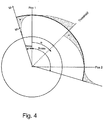
- Fig. 4
- is a graph showing dynamic step sizes and dynamic hard stops of the selection element.
-
Fig. 1 shows a schematic top view of a proposedselection unit 100 as can be seen by a flight crewmember. Theselection unit 100 is installed in an overhead panel in the cockpit. Theselection unit 100 allows selection of threedifferent states Normal Operation 1",state 102 "Emergency Operation" andstate 103 "Normal Operation 2". - The
selection unit 100 comprises a manuallyoperable selection element 200. Theselection element 200 is designed as a rotary switch with anouter ring 104 as a rotatable part and anon-rotatable part 105 of the switch. Theselection element 200 comprising afirst display 105, which equals the non-rotatable part of the rotary switch indicating the actual selection,state 107 of theselection element 200. Eachpossible selection state selection element 200 represents one of the above-described states: 101, 102, 103 of the hydraulic pressure system and is indicated inFig. 1 as arrow pointing in different directions. In reality all dotted lines, i.e. all non active/actually selected links ofFig. 1 are not displayed on the first and second display to avoid confusion. For a selection of a state of the aircraft system therotatable part 104 must be manually rotated in the respective direction (left / right). A selection of thestate 102 "Emergeny Operation" requires a respective rotation of therotatable part 104 and two pushes on the non-rotatable part within 2 seconds. This safety feature should avoid unintended activation of the "Emergency Operation". - The
selection element 200 is additionally designed and configured for a dynamic electronic selection of its actual state on an external signal input. The input signal may be automatically generated by an ECAM (= Electronic Centralized Aircraft Monitor) system of the aircraft. - Further, the
selection unit 100 comprises asecond display 113, which in this example is a graphical colour display. Theselection element 200 and anotherinput device 114 are arranged within thesecond display 113, i.e. the graphical colour display is arranged around theselection element 200 and thedevice 114. Thesecond display 113 is visualizing a schematic of the aircraft system with highlighting the actual state 101 ("Normal Operation 1") of the aircraft system depending on theactual selection state 107 of theselection element 200. Following a dynamic change of the actual state of the selection element 200 (representing a dynamic change of the actual state of the aircraft system) the content of the second display is changed accordingly showing now the new actual state of the aircraft system. - The schematic of the aircraft system in this example comprising different subsystems 108 - 112 which could be supplied by hydraulic power depending on the selection state of the
selection element 200. The actual state 107 (=Normal Operation 1") of the hydraulic system is represented on thesecond display 113 by highlighting thesubsystems actual system state 101 corresponding with theactual state 107 of theselector element 200 thesubsystems - All elements: 102-103, 108-112 including their active links are shown on the
second display 113. All dotted links are only shown inFig. 1 for information, i.e. all elements shown in thedisplay 113 except the manual input devices:rotary switch 200 and anothermanual selector 114 for selecting the aircraft system from several aircraft systems is dynamically generated by respective driving software of thesecond display 113. This provides a great flexibility, because the proposedselection unit 100 is usable for different aircraft systems. Further it needs only oneselection unit 200 for controlling different aircraft systems or functions. With manual selector, 114 (may be a toggle switch or push button switch or rotary switch an actual aircraft system can be selected from the number of aircraft systems. With each selection of an aircraft system with thedevice 114, the relevant system schematic is shown on thesecond display 113 including the actual state of the respective system. Further, following the selection of aircraft system, the respective selection states of theselector element 200 are indicated on thesecond display 113, and theselector element 200 shows its actual selection state corresponding to the actual selection state of the selected aircraft system. The proposedselection unit 100 provides a great variety and flexibility in manual and dynamic controlling of one or more aircraft systems. - The
selection unit 100 may combine the benefits of a haptic switch with the flexibility of a touch screen assecond display 113. The touch screen may allow for a selection between differently detailed system schematics. - Some possible use-cases are:
- Changing the number of selectable items
- Highlight inactive or unavailable items
- Highlight the next or recommended action
- Rearrange the selectable items
- In case of a dynamic electronic selection of the
actual selection state 107 based on an external signal input, for example from the ECAM system, the indicatedactual selection state 107 of theselection element 200 is automatically changed accordingly. - In general, if a system state activated/changed automatically or via the ECAM system, the
selection element 200 should turn to a new position automatically. Otherwise, theselection unit 100 and the ECAM would display two different system states. If the implementation of such an active moving switch is difficult, only the indication could be changed as realized in current example ofFig.1 . -
Fig. 2 presents a schematic top view of a proposedselection element 200. Theselection element 200 is designed and configured as a rotary switch comprising a manuallyrotatable part 104 formed as a ring and a non-rotatable part in the middle of thering 104. The non-rotatable part comprises thefirst display 105 indicating theactual selection state 107 of the selection element 200 (= rotary switch). The other possible selection states are indicated for information only by dotted lines. Only theactual status 107 of selection element is illuminated/shown in the rotary switch in reality. - In the rotary switch of
Fig. 1 andFig. 2 there is no hard stop for therotating part 104 of the rotary switch. If hard stops should be included, they have to be dynamic. - A first concept mixes an electromagnetic brake with mechanical thresholds as used in today's rotary switches. A mechanically fixed distance between the thresholds is assumed. In
Fig. 3 a ball that is pressed against geometry that recreates the thresholds each 'valley' represents a selectable item and each 'hill' the threshold that has to be overcome in order to turn the switch simplifies this mechanical locking. A sensor monitors the current position of the switch (α). If a reaches αmax or αmin' an electromagnetic brake, that acts against direction of rotation, is activated. This brake must be strong enough to inhibit any further movement. αmax and αmin' can be set dynamically. - Example: a pilot sets the rotary switch to 'Pos 1'. Thus, the switch is at its left limit. If the system (e.g. ECAM) switches via software to 'Pos 2', the indication on the switch (first display) would change accordingly, but the left limit would persist. By turning the αmax and αmin' values the limits would be moved in such a way that the switch is now at the right limit. A selection element may also be dynamically disabled or the number of selectable states may be changed dynamically. This could be reflected in a haptic feedback with hard stops.
- In the second concept, (see
Fig. 4 ) the mechanical locking is removed to enable dynamic distances of the thresholds. The mechanical locking works against and in the direction of orientation. Therefore, an electromagnetic brake cannot be used. An active actuator rather can replace it. InFig. 4 shows the torque in relation to α. As this curve can be dynamically adapted, the arrangement and the distance of different items can be changed with the appropriate haptic feedback. Furthermore, this actuator will retract the button to a distinct position if it is released near a threshold. This concept needs an actuator to apply torque to the rotary switch. Regarding the simple problem of indication mismatch between the actual status of the aircraft system and the status displayed by theselection unit 100, this actuator could be used to rotate a non-rotationally symmetric button to the appropriate position. -
- 100
- selection unit
- 101-103
- indication of different states or functions of an aircraft system
- 104
- rotatable part of a rotary switch
- 105
- non-rotatable part of a rotary switch comprising the first display
- 106a,b
- possible states of the selection element
- 107
- actual state of the selection element
- 108-112
- elements/devices of the aircraft system
- 113
- second display
- 114
- selection device for selecting the actual aircraft system, which is controlled by the selection unit
Claims (12)
- Selection unit (100) for selecting different states or functions (101-103) of an aircraft system, comprising:- a manually operable selection element (200), the selection element (200) comprising a first display (105) indicating the actual selection state (107) of the selection element (200), with each selection state (106a, 106b, 107) of the selection element (200) representing a different state or function (101-103) of the aircraft system,the selection unit (100) being characterized
in that said selection element (200) is additionally designed and configured for an automatic electronic selection of the actual selection state (107) based on an external signal input, and
by comprising - a second display (113) co-located with the selection element (200), the second display (113) visualizing the actual state (101) of the aircraft system depending on the actual selection state (107) of the selection element (200), wherein said selection element (200) is designed and configured as a rotary switch or as a push button switch or as a toggle switch or as a rocker switch. - Selection unit (100) of Claim 1, comprising an actuator for physically moving the selection element (200) into a selection position corresponding with the actual selection state (107).
- Selection unit (100) of Claim 1, wherein said rotary switch is additionally designed and configured for providing a push button function, wherein an actual selection state (107) of the rotary switch (200) may manually only be changed by a combination of manually turning the rotary switch (200) and manually pushing the rotary switch (200).
- Selection unit (100) of one of the preceding claims, wherein said selection element (200) is a rotary switch comprising a rotatable outer element (104) surrounding an inner non-rotatable part which is comprising the first display (105).
- Selection unit (100) of one of the preceding claims, wherein said selection element (200) is designed and configured as a rotary switch with a rotatable part (104), said rotary switch (200) comprising at least one dynamically allocatable hard stop position for the rotatable part (104) based on an external signal input preventing a further rotation of a rotatable part (104) beyond the hard stop position.
- Selection unit (100) of one of the preceding claims, wherein said selection element (200) is designed and configured as a rotary switch with at least one dynamically allocatable mechanical threshold switch position based on an external signal input allowing a further rotation of a rotatable part (104) of the rotary switch (200) beyond the mechanical threshold position only when applying a force for overcoming the mechanical threshold.
- Selection unit (100) of Claim 6, wherein said selection element (200) comprising an electromagnetic brake for realizing the mechanical threshold.
- Selection unit (100) of one of the preceding claims, wherein the external signal input for the dynamic electronic selection of the actual selection state (107) is depending on an aircraft system selectable from a number of aircraft systems and/or an actual system status of the aircraft system.
- Selection unit (100) of Claim 8, comprising an input device (114) for manually selecting the aircraft system from the number of aircraft systems.
- Selection unit (100) of one of the preceding claims, wherein the first display (105) and /or the second display (113) comprising one or more of the following list:- one or more LEDs- one or more light conducting elements- graphical monitor display for example LED-, LCD-, Plasma- OELD- and/or Retina display.
- Aircraft system with a selection unit (100) according to one of the preceding claims.
- Aircraft with a selection unit (100) according to one of the preceding claims.
Priority Applications (2)
| Application Number | Priority Date | Filing Date | Title |
|---|---|---|---|
| EP14192095.9A EP3018571B1 (en) | 2014-11-06 | 2014-11-06 | Selection unit to select or control different states or functions of an aircraft system |
| US14/934,788 US10416793B2 (en) | 2014-11-06 | 2015-11-06 | Selection unit to select or control different states or functions of an aircraft system |
Applications Claiming Priority (1)
| Application Number | Priority Date | Filing Date | Title |
|---|---|---|---|
| EP14192095.9A EP3018571B1 (en) | 2014-11-06 | 2014-11-06 | Selection unit to select or control different states or functions of an aircraft system |
Publications (2)
| Publication Number | Publication Date |
|---|---|
| EP3018571A1 EP3018571A1 (en) | 2016-05-11 |
| EP3018571B1 true EP3018571B1 (en) | 2021-03-10 |
Family
ID=51870890
Family Applications (1)
| Application Number | Title | Priority Date | Filing Date |
|---|---|---|---|
| EP14192095.9A Active EP3018571B1 (en) | 2014-11-06 | 2014-11-06 | Selection unit to select or control different states or functions of an aircraft system |
Country Status (2)
| Country | Link |
|---|---|
| US (1) | US10416793B2 (en) |
| EP (1) | EP3018571B1 (en) |
Families Citing this family (1)
| Publication number | Priority date | Publication date | Assignee | Title |
|---|---|---|---|---|
| FR3044434B1 (en) * | 2015-12-01 | 2018-06-15 | Dassault Aviation | INTERFACE SYSTEM BETWEEN A DISPLAY USER IN THE COCKPIT OF AN AIRCRAFT, AIRCRAFT AND ASSOCIATED METHOD |
Citations (6)
| Publication number | Priority date | Publication date | Assignee | Title |
|---|---|---|---|---|
| US20040015274A1 (en) * | 2001-10-11 | 2004-01-22 | Wilkins Robert Ryan | Flight guidance system providing perspective flight guidance symbology |
| US20070159452A1 (en) * | 2003-09-03 | 2007-07-12 | Siemens Aktiengesellschaft | Operating element for a multi-media system in a motor vehicle |
| US20070179684A1 (en) * | 2006-02-02 | 2007-08-02 | Honeywell International Inc. | Heading awareness symbology for track centered primary flight displays |
| US20080198157A1 (en) * | 2007-02-16 | 2008-08-21 | Honeywell International, Inc. | Target zone display system and method |
| US8264378B1 (en) * | 2009-09-17 | 2012-09-11 | The Boeing Company | Aircraft display center and range control |
| US20120267221A1 (en) * | 2011-04-25 | 2012-10-25 | Daesung Electric Co., Ltd | Haptic steering wheel switch apparatus and haptic steering wheel swtich system including the same |
Family Cites Families (6)
| Publication number | Priority date | Publication date | Assignee | Title |
|---|---|---|---|---|
| JP2005223524A (en) * | 2004-02-04 | 2005-08-18 | Nissan Motor Co Ltd | Supervisory apparatus for surrounding of vehicle |
| US7403133B2 (en) * | 2005-10-13 | 2008-07-22 | Honeywell International, Inc. | Dynamic primary flight displays for unusual attitude conditions |
| FR2917223B1 (en) * | 2007-06-08 | 2009-07-17 | Thales Sa | AIDING SYSTEM FOR GUIDING AN AIRCRAFT ON AN AIRPORT |
| JP4965656B2 (en) * | 2007-08-07 | 2012-07-04 | 株式会社オートネットワーク技術研究所 | Operating device |
| DE102010013170A1 (en) * | 2010-03-27 | 2011-09-29 | Audi Ag | Device for operating different functions of a motor vehicle |
| US9519349B2 (en) * | 2014-10-30 | 2016-12-13 | Industrial Smoke & Mirrors, Inc. | Touch screen interface device |
-
2014
- 2014-11-06 EP EP14192095.9A patent/EP3018571B1/en active Active
-
2015
- 2015-11-06 US US14/934,788 patent/US10416793B2/en active Active
Patent Citations (6)
| Publication number | Priority date | Publication date | Assignee | Title |
|---|---|---|---|---|
| US20040015274A1 (en) * | 2001-10-11 | 2004-01-22 | Wilkins Robert Ryan | Flight guidance system providing perspective flight guidance symbology |
| US20070159452A1 (en) * | 2003-09-03 | 2007-07-12 | Siemens Aktiengesellschaft | Operating element for a multi-media system in a motor vehicle |
| US20070179684A1 (en) * | 2006-02-02 | 2007-08-02 | Honeywell International Inc. | Heading awareness symbology for track centered primary flight displays |
| US20080198157A1 (en) * | 2007-02-16 | 2008-08-21 | Honeywell International, Inc. | Target zone display system and method |
| US8264378B1 (en) * | 2009-09-17 | 2012-09-11 | The Boeing Company | Aircraft display center and range control |
| US20120267221A1 (en) * | 2011-04-25 | 2012-10-25 | Daesung Electric Co., Ltd | Haptic steering wheel switch apparatus and haptic steering wheel swtich system including the same |
Also Published As
| Publication number | Publication date |
|---|---|
| EP3018571A1 (en) | 2016-05-11 |
| US20160132134A1 (en) | 2016-05-12 |
| US10416793B2 (en) | 2019-09-17 |
Similar Documents
| Publication | Publication Date | Title |
|---|---|---|
| EP2264564B1 (en) | Vehicle commander control switch and method | |
| US20080078868A1 (en) | System and method for a power-assisted compartment | |
| EP3299293B1 (en) | A passenger supply unit for an aircraft cabin | |
| EP2741200B1 (en) | Method and device for operating an electronic device | |
| US8065463B2 (en) | Multi-purpose flight attendant panel | |
| KR20160030837A (en) | Switch array utilizing touch screen technology and haptics feedback | |
| CA2954962A1 (en) | Virtual aircraft operations checklist | |
| US9121487B2 (en) | Pilot interface for aircraft electric taxi system | |
| CN110510134B (en) | Aircraft flight navigation panel with display arranged between two input parts | |
| US10595386B2 (en) | Lighting control console having a dual encoder | |
| EP3018571B1 (en) | Selection unit to select or control different states or functions of an aircraft system | |
| CN106240831B (en) | Configurable control panel for an aircraft cockpit and method for configuring such a panel | |
| US10407180B2 (en) | Interface system between a user and a display device in the cockpit of an aircraft, related aircraft and method | |
| KR20170061515A (en) | An user input apparatus for multifunctional control console and method for controlling the same | |
| KR102510409B1 (en) | Display and operating device for a vehicle component | |
| US20210171068A1 (en) | Drive controller of a rail vehicle | |
| DE102016220244A1 (en) | Central operating and display unit for a motor vehicle | |
| US20160085367A1 (en) | Systeme d'entree de donnee multimode | |
| US20170355383A1 (en) | Operating unit for a motor vehicle and method for operating an operating unit of a motor vehicle | |
| JP2010188862A (en) | Steering switch device | |
| EP3020131B1 (en) | Control panel for aircraft | |
| US10135927B1 (en) | ARINC 661 display system and methods incorporating non-ARINC 661 protocols | |
| US9940895B1 (en) | Displays with safety segregation | |
| EP4289725A1 (en) | Aircraft system controller and associated method | |
| US6505115B2 (en) | Device for controlling a system for monitoring the environment of an aircraft, in particular of a transport aircraft |
Legal Events
| Date | Code | Title | Description |
|---|---|---|---|
| PUAI | Public reference made under article 153(3) epc to a published international application that has entered the european phase |
Free format text: ORIGINAL CODE: 0009012 |
|
| AK | Designated contracting states |
Kind code of ref document: A1 Designated state(s): AL AT BE BG CH CY CZ DE DK EE ES FI FR GB GR HR HU IE IS IT LI LT LU LV MC MK MT NL NO PL PT RO RS SE SI SK SM TR |
|
| AX | Request for extension of the european patent |
Extension state: BA ME |
|
| STAA | Information on the status of an ep patent application or granted ep patent |
Free format text: STATUS: REQUEST FOR EXAMINATION WAS MADE |
|
| 17P | Request for examination filed |
Effective date: 20161103 |
|
| RBV | Designated contracting states (corrected) |
Designated state(s): AL AT BE BG CH CY CZ DE DK EE ES FI FR GB GR HR HU IE IS IT LI LT LU LV MC MK MT NL NO PL PT RO RS SE SI SK SM TR |
|
| STAA | Information on the status of an ep patent application or granted ep patent |
Free format text: STATUS: EXAMINATION IS IN PROGRESS |
|
| 17Q | First examination report despatched |
Effective date: 20181023 |
|
| REG | Reference to a national code |
Ref country code: DE Ref legal event code: R079 Ref document number: 602014075513 Country of ref document: DE Free format text: PREVIOUS MAIN CLASS: G06F0003048800 Ipc: B64C0019000000 |
|
| RIC1 | Information provided on ipc code assigned before grant |
Ipc: B64D 45/00 20060101ALI20200729BHEP Ipc: B64C 19/00 20060101AFI20200729BHEP |
|
| GRAP | Despatch of communication of intention to grant a patent |
Free format text: ORIGINAL CODE: EPIDOSNIGR1 |
|
| STAA | Information on the status of an ep patent application or granted ep patent |
Free format text: STATUS: GRANT OF PATENT IS INTENDED |
|
| INTG | Intention to grant announced |
Effective date: 20201008 |
|
| GRAS | Grant fee paid |
Free format text: ORIGINAL CODE: EPIDOSNIGR3 |
|
| STAA | Information on the status of an ep patent application or granted ep patent |
Free format text: STATUS: GRANT OF PATENT IS INTENDED |
|
| GRAA | (expected) grant |
Free format text: ORIGINAL CODE: 0009210 |
|
| STAA | Information on the status of an ep patent application or granted ep patent |
Free format text: STATUS: THE PATENT HAS BEEN GRANTED |
|
| RAP1 | Party data changed (applicant data changed or rights of an application transferred) |
Owner name: AIRBUS DEFENCE AND SPACE GMBH |
|
| AK | Designated contracting states |
Kind code of ref document: B1 Designated state(s): AL AT BE BG CH CY CZ DE DK EE ES FI FR GB GR HR HU IE IS IT LI LT LU LV MC MK MT NL NO PL PT RO RS SE SI SK SM TR |
|
| REG | Reference to a national code |
Ref country code: GB Ref legal event code: FG4D |
|
| REG | Reference to a national code |
Ref country code: AT Ref legal event code: REF Ref document number: 1369567 Country of ref document: AT Kind code of ref document: T Effective date: 20210315 Ref country code: CH Ref legal event code: EP |
|
| REG | Reference to a national code |
Ref country code: DE Ref legal event code: R096 Ref document number: 602014075513 Country of ref document: DE |
|
| REG | Reference to a national code |
Ref country code: IE Ref legal event code: FG4D |
|
| REG | Reference to a national code |
Ref country code: LT Ref legal event code: MG9D |
|
| PG25 | Lapsed in a contracting state [announced via postgrant information from national office to epo] |
Ref country code: FI Free format text: LAPSE BECAUSE OF FAILURE TO SUBMIT A TRANSLATION OF THE DESCRIPTION OR TO PAY THE FEE WITHIN THE PRESCRIBED TIME-LIMIT Effective date: 20210310 Ref country code: GR Free format text: LAPSE BECAUSE OF FAILURE TO SUBMIT A TRANSLATION OF THE DESCRIPTION OR TO PAY THE FEE WITHIN THE PRESCRIBED TIME-LIMIT Effective date: 20210611 Ref country code: HR Free format text: LAPSE BECAUSE OF FAILURE TO SUBMIT A TRANSLATION OF THE DESCRIPTION OR TO PAY THE FEE WITHIN THE PRESCRIBED TIME-LIMIT Effective date: 20210310 Ref country code: LT Free format text: LAPSE BECAUSE OF FAILURE TO SUBMIT A TRANSLATION OF THE DESCRIPTION OR TO PAY THE FEE WITHIN THE PRESCRIBED TIME-LIMIT Effective date: 20210310 Ref country code: BG Free format text: LAPSE BECAUSE OF FAILURE TO SUBMIT A TRANSLATION OF THE DESCRIPTION OR TO PAY THE FEE WITHIN THE PRESCRIBED TIME-LIMIT Effective date: 20210610 Ref country code: NO Free format text: LAPSE BECAUSE OF FAILURE TO SUBMIT A TRANSLATION OF THE DESCRIPTION OR TO PAY THE FEE WITHIN THE PRESCRIBED TIME-LIMIT Effective date: 20210610 |
|
| REG | Reference to a national code |
Ref country code: AT Ref legal event code: MK05 Ref document number: 1369567 Country of ref document: AT Kind code of ref document: T Effective date: 20210310 |
|
| REG | Reference to a national code |
Ref country code: NL Ref legal event code: MP Effective date: 20210310 |
|
| PG25 | Lapsed in a contracting state [announced via postgrant information from national office to epo] |
Ref country code: SE Free format text: LAPSE BECAUSE OF FAILURE TO SUBMIT A TRANSLATION OF THE DESCRIPTION OR TO PAY THE FEE WITHIN THE PRESCRIBED TIME-LIMIT Effective date: 20210310 Ref country code: LV Free format text: LAPSE BECAUSE OF FAILURE TO SUBMIT A TRANSLATION OF THE DESCRIPTION OR TO PAY THE FEE WITHIN THE PRESCRIBED TIME-LIMIT Effective date: 20210310 Ref country code: RS Free format text: LAPSE BECAUSE OF FAILURE TO SUBMIT A TRANSLATION OF THE DESCRIPTION OR TO PAY THE FEE WITHIN THE PRESCRIBED TIME-LIMIT Effective date: 20210310 |
|
| PG25 | Lapsed in a contracting state [announced via postgrant information from national office to epo] |
Ref country code: NL Free format text: LAPSE BECAUSE OF FAILURE TO SUBMIT A TRANSLATION OF THE DESCRIPTION OR TO PAY THE FEE WITHIN THE PRESCRIBED TIME-LIMIT Effective date: 20210310 |
|
| PG25 | Lapsed in a contracting state [announced via postgrant information from national office to epo] |
Ref country code: SM Free format text: LAPSE BECAUSE OF FAILURE TO SUBMIT A TRANSLATION OF THE DESCRIPTION OR TO PAY THE FEE WITHIN THE PRESCRIBED TIME-LIMIT Effective date: 20210310 Ref country code: AT Free format text: LAPSE BECAUSE OF FAILURE TO SUBMIT A TRANSLATION OF THE DESCRIPTION OR TO PAY THE FEE WITHIN THE PRESCRIBED TIME-LIMIT Effective date: 20210310 Ref country code: CZ Free format text: LAPSE BECAUSE OF FAILURE TO SUBMIT A TRANSLATION OF THE DESCRIPTION OR TO PAY THE FEE WITHIN THE PRESCRIBED TIME-LIMIT Effective date: 20210310 Ref country code: EE Free format text: LAPSE BECAUSE OF FAILURE TO SUBMIT A TRANSLATION OF THE DESCRIPTION OR TO PAY THE FEE WITHIN THE PRESCRIBED TIME-LIMIT Effective date: 20210310 |
|
| PG25 | Lapsed in a contracting state [announced via postgrant information from national office to epo] |
Ref country code: IS Free format text: LAPSE BECAUSE OF FAILURE TO SUBMIT A TRANSLATION OF THE DESCRIPTION OR TO PAY THE FEE WITHIN THE PRESCRIBED TIME-LIMIT Effective date: 20210710 Ref country code: RO Free format text: LAPSE BECAUSE OF FAILURE TO SUBMIT A TRANSLATION OF THE DESCRIPTION OR TO PAY THE FEE WITHIN THE PRESCRIBED TIME-LIMIT Effective date: 20210310 Ref country code: SK Free format text: LAPSE BECAUSE OF FAILURE TO SUBMIT A TRANSLATION OF THE DESCRIPTION OR TO PAY THE FEE WITHIN THE PRESCRIBED TIME-LIMIT Effective date: 20210310 Ref country code: PT Free format text: LAPSE BECAUSE OF FAILURE TO SUBMIT A TRANSLATION OF THE DESCRIPTION OR TO PAY THE FEE WITHIN THE PRESCRIBED TIME-LIMIT Effective date: 20210712 Ref country code: PL Free format text: LAPSE BECAUSE OF FAILURE TO SUBMIT A TRANSLATION OF THE DESCRIPTION OR TO PAY THE FEE WITHIN THE PRESCRIBED TIME-LIMIT Effective date: 20210310 Ref country code: ES Free format text: LAPSE BECAUSE OF FAILURE TO SUBMIT A TRANSLATION OF THE DESCRIPTION OR TO PAY THE FEE WITHIN THE PRESCRIBED TIME-LIMIT Effective date: 20210310 |
|
| REG | Reference to a national code |
Ref country code: DE Ref legal event code: R097 Ref document number: 602014075513 Country of ref document: DE |
|
| PLBE | No opposition filed within time limit |
Free format text: ORIGINAL CODE: 0009261 |
|
| STAA | Information on the status of an ep patent application or granted ep patent |
Free format text: STATUS: NO OPPOSITION FILED WITHIN TIME LIMIT |
|
| PG25 | Lapsed in a contracting state [announced via postgrant information from national office to epo] |
Ref country code: DK Free format text: LAPSE BECAUSE OF FAILURE TO SUBMIT A TRANSLATION OF THE DESCRIPTION OR TO PAY THE FEE WITHIN THE PRESCRIBED TIME-LIMIT Effective date: 20210310 Ref country code: AL Free format text: LAPSE BECAUSE OF FAILURE TO SUBMIT A TRANSLATION OF THE DESCRIPTION OR TO PAY THE FEE WITHIN THE PRESCRIBED TIME-LIMIT Effective date: 20210310 |
|
| 26N | No opposition filed |
Effective date: 20211213 |
|
| PG25 | Lapsed in a contracting state [announced via postgrant information from national office to epo] |
Ref country code: SI Free format text: LAPSE BECAUSE OF FAILURE TO SUBMIT A TRANSLATION OF THE DESCRIPTION OR TO PAY THE FEE WITHIN THE PRESCRIBED TIME-LIMIT Effective date: 20210310 |
|
| PG25 | Lapsed in a contracting state [announced via postgrant information from national office to epo] |
Ref country code: IT Free format text: LAPSE BECAUSE OF FAILURE TO SUBMIT A TRANSLATION OF THE DESCRIPTION OR TO PAY THE FEE WITHIN THE PRESCRIBED TIME-LIMIT Effective date: 20210310 |
|
| PG25 | Lapsed in a contracting state [announced via postgrant information from national office to epo] |
Ref country code: IS Free format text: LAPSE BECAUSE OF FAILURE TO SUBMIT A TRANSLATION OF THE DESCRIPTION OR TO PAY THE FEE WITHIN THE PRESCRIBED TIME-LIMIT Effective date: 20210710 |
|
| PG25 | Lapsed in a contracting state [announced via postgrant information from national office to epo] |
Ref country code: MC Free format text: LAPSE BECAUSE OF FAILURE TO SUBMIT A TRANSLATION OF THE DESCRIPTION OR TO PAY THE FEE WITHIN THE PRESCRIBED TIME-LIMIT Effective date: 20210310 |
|
| REG | Reference to a national code |
Ref country code: CH Ref legal event code: PL |
|
| PG25 | Lapsed in a contracting state [announced via postgrant information from national office to epo] |
Ref country code: LU Free format text: LAPSE BECAUSE OF NON-PAYMENT OF DUE FEES Effective date: 20211106 Ref country code: BE Free format text: LAPSE BECAUSE OF NON-PAYMENT OF DUE FEES Effective date: 20211130 |
|
| REG | Reference to a national code |
Ref country code: BE Ref legal event code: MM Effective date: 20211130 |
|
| PG25 | Lapsed in a contracting state [announced via postgrant information from national office to epo] |
Ref country code: IE Free format text: LAPSE BECAUSE OF NON-PAYMENT OF DUE FEES Effective date: 20211106 |
|
| PG25 | Lapsed in a contracting state [announced via postgrant information from national office to epo] |
Ref country code: HU Free format text: LAPSE BECAUSE OF FAILURE TO SUBMIT A TRANSLATION OF THE DESCRIPTION OR TO PAY THE FEE WITHIN THE PRESCRIBED TIME-LIMIT; INVALID AB INITIO Effective date: 20141106 |
|
| PG25 | Lapsed in a contracting state [announced via postgrant information from national office to epo] |
Ref country code: CY Free format text: LAPSE BECAUSE OF FAILURE TO SUBMIT A TRANSLATION OF THE DESCRIPTION OR TO PAY THE FEE WITHIN THE PRESCRIBED TIME-LIMIT Effective date: 20210310 |
|
| PG25 | Lapsed in a contracting state [announced via postgrant information from national office to epo] |
Ref country code: LI Free format text: LAPSE BECAUSE OF NON-PAYMENT OF DUE FEES Effective date: 20220701 Ref country code: CH Free format text: LAPSE BECAUSE OF NON-PAYMENT OF DUE FEES Effective date: 20220701 |
|
| PGFP | Annual fee paid to national office [announced via postgrant information from national office to epo] |
Ref country code: GB Payment date: 20231123 Year of fee payment: 10 |
|
| PGFP | Annual fee paid to national office [announced via postgrant information from national office to epo] |
Ref country code: FR Payment date: 20231120 Year of fee payment: 10 Ref country code: DE Payment date: 20231121 Year of fee payment: 10 |
|
| PG25 | Lapsed in a contracting state [announced via postgrant information from national office to epo] |
Ref country code: MK Free format text: LAPSE BECAUSE OF FAILURE TO SUBMIT A TRANSLATION OF THE DESCRIPTION OR TO PAY THE FEE WITHIN THE PRESCRIBED TIME-LIMIT Effective date: 20210310 |