EP3016582B1 - Photoplethysmography sensor apparatus and method - Google Patents
Photoplethysmography sensor apparatus and method Download PDFInfo
- Publication number
- EP3016582B1 EP3016582B1 EP15731553.2A EP15731553A EP3016582B1 EP 3016582 B1 EP3016582 B1 EP 3016582B1 EP 15731553 A EP15731553 A EP 15731553A EP 3016582 B1 EP3016582 B1 EP 3016582B1
- Authority
- EP
- European Patent Office
- Prior art keywords
- sensor apparatus
- photoplethysmography sensor
- signal
- unit
- light
- Prior art date
- Legal status (The legal status is an assumption and is not a legal conclusion. Google has not performed a legal analysis and makes no representation as to the accuracy of the status listed.)
- Active
Links
- 238000013186 photoplethysmography Methods 0.000 title claims description 103
- 238000000034 method Methods 0.000 title claims description 13
- 230000001360 synchronised effect Effects 0.000 claims description 40
- 238000004590 computer program Methods 0.000 claims description 12
- 238000010521 absorption reaction Methods 0.000 claims description 6
- 230000004044 response Effects 0.000 claims description 5
- 238000005070 sampling Methods 0.000 description 8
- 238000005259 measurement Methods 0.000 description 7
- 230000008901 benefit Effects 0.000 description 5
- 230000003287 optical effect Effects 0.000 description 5
- 210000001519 tissue Anatomy 0.000 description 5
- 230000001419 dependent effect Effects 0.000 description 4
- 230000005284 excitation Effects 0.000 description 4
- 210000003491 skin Anatomy 0.000 description 4
- 230000003321 amplification Effects 0.000 description 3
- 239000008280 blood Substances 0.000 description 3
- 210000004369 blood Anatomy 0.000 description 3
- 239000003990 capacitor Substances 0.000 description 3
- 238000012937 correction Methods 0.000 description 3
- 230000010354 integration Effects 0.000 description 3
- 230000002452 interceptive effect Effects 0.000 description 3
- 238000003199 nucleic acid amplification method Methods 0.000 description 3
- 230000009471 action Effects 0.000 description 2
- 238000006243 chemical reaction Methods 0.000 description 2
- 210000000624 ear auricle Anatomy 0.000 description 2
- 238000001914 filtration Methods 0.000 description 2
- 210000000056 organ Anatomy 0.000 description 2
- 230000010363 phase shift Effects 0.000 description 2
- 238000012545 processing Methods 0.000 description 2
- 230000002040 relaxant effect Effects 0.000 description 2
- 230000001629 suppression Effects 0.000 description 2
- 230000002238 attenuated effect Effects 0.000 description 1
- 230000008859 change Effects 0.000 description 1
- 230000008878 coupling Effects 0.000 description 1
- 238000010168 coupling process Methods 0.000 description 1
- 238000005859 coupling reaction Methods 0.000 description 1
- 210000004207 dermis Anatomy 0.000 description 1
- 238000013461 design Methods 0.000 description 1
- 238000001514 detection method Methods 0.000 description 1
- 230000006870 function Effects 0.000 description 1
- 230000031700 light absorption Effects 0.000 description 1
- 238000004519 manufacturing process Methods 0.000 description 1
- 230000007246 mechanism Effects 0.000 description 1
- 206010033675 panniculitis Diseases 0.000 description 1
- 230000010412 perfusion Effects 0.000 description 1
- 230000000737 periodic effect Effects 0.000 description 1
- 238000002106 pulse oximetry Methods 0.000 description 1
- 238000009738 saturating Methods 0.000 description 1
- 239000004065 semiconductor Substances 0.000 description 1
- 230000003595 spectral effect Effects 0.000 description 1
- 210000004304 subcutaneous tissue Anatomy 0.000 description 1
- 230000002123 temporal effect Effects 0.000 description 1
- 238000012360 testing method Methods 0.000 description 1
- 210000000707 wrist Anatomy 0.000 description 1
Images

Classifications
-
- A—HUMAN NECESSITIES
- A61—MEDICAL OR VETERINARY SCIENCE; HYGIENE
- A61B—DIAGNOSIS; SURGERY; IDENTIFICATION
- A61B5/00—Measuring for diagnostic purposes; Identification of persons
- A61B5/02—Detecting, measuring or recording pulse, heart rate, blood pressure or blood flow; Combined pulse/heart-rate/blood pressure determination; Evaluating a cardiovascular condition not otherwise provided for, e.g. using combinations of techniques provided for in this group with electrocardiography or electroauscultation; Heart catheters for measuring blood pressure
- A61B5/024—Detecting, measuring or recording pulse rate or heart rate
- A61B5/02416—Detecting, measuring or recording pulse rate or heart rate using photoplethysmograph signals, e.g. generated by infrared radiation
- A61B5/02427—Details of sensor
-
- A—HUMAN NECESSITIES
- A61—MEDICAL OR VETERINARY SCIENCE; HYGIENE
- A61B—DIAGNOSIS; SURGERY; IDENTIFICATION
- A61B5/00—Measuring for diagnostic purposes; Identification of persons
- A61B5/72—Signal processing specially adapted for physiological signals or for diagnostic purposes
- A61B5/7203—Signal processing specially adapted for physiological signals or for diagnostic purposes for noise prevention, reduction or removal
Definitions
- the invention relates to a photoplethysmography sensor apparatus, a photoplethysmography sensor method, and a photoplethysmography sensor computer program.
- Photoplethysmography refers to acquiring a volumetric organ measurement by optical means. Frequently, pulse oximeters are employed, which detect changes in light absorption properties of the human skin. Typically, a transmissive or reflective blood PPG sensor monitors the perfusion of blood to the dermis and subcutaneous tissue of the skin through absorption measurement at a specific wavelength. Besides light originating from blood, there is a far greater portion of light detected, which originates from tissue and ambient light.
- Photoplethysmography signals comprise a very small AC signal (the actual plethysmogram) on top of a very large (unwanted) DC offset signal.
- the DC offset signal comprises signals originating from skin and tissue, and from a considerable part of ambient light.
- the temporal rate of change of detected ambient light includes frequencies in the photoplethysmography frequency band of interest. This prohibits simple frequency domain filtering, because filtering out these frequencies (in the hope of suppressing the detected ambient light) would also filter (or significantly suppress) frequencies of the photoplethysmography frequency band of interest.
- DC-restore circuits which sample the ambient light periodically when the photoplethysmography excitation light (such as, e.g., a light-emitting diode, LED) is temporarily turned off. In a different time slot (e.g., when the LED is turned on) a sample is taken which contains both ambient and the photoplethysmography signal. By subtracting the signal with the photoplethysmography excitation light turned off from the signal with the photoplethysmography excitation light turned on, an "offset-corrected" photoplethysmography signal is obtained, which does not exhibit interference from ambient light.
- the photoplethysmography excitation light such as, e.g., a light-emitting diode, LED
- this sampling is done after a transimpedance amplifier (TIA) has converted and amplified the photocurrent generated by the detector into a voltage.
- TIA transimpedance amplifier
- ADC analog-to-digital converter
- a sample-and-hold circuit is needed to hold the ambient value (i.e., the measurement value corresponding to the ambient light) until the next sampling period of the photoplethysmography signal.
- the gain accuracy of this sample-and-hold signal determines the efficacy of the compensation.
- US 7740591 discloses a plethysmography sensor.
- This sensor comprises an ambient light canceling circuit that receives the output of transimpedance differential amplifiers.
- the ambient light canceling circuit operates as follows: when timing control circuit has both the Red and IR LED's off, the ambient light is the only light the sensor has for an output. The ambient light is sampled, and the value of the signal is held in a capacitor tied to ground using a FET. When the FET is turned off, the value stored in the capacitor is used in the path of the Red and IR signal string. This stored value in the capacitor removes the error of the ambient light.
- US6381479B1 discloses a system for providing an improved DC and low frequency signal rejection in a photoplethysmographic measurement instrument.
- the system is used in a measurement instrument which includes at least two signal sources for transmitting light signals at least at two wavelengths through a tissue of a test subject and a detector for converting light signals transmitted through the tissue into a detector output signal.
- the system includes a DC restoration which removes DC and low frequency signal components from the detector output signal prior to amplification thereof so as to avoid saturating amplified output signal with the low frequency signal component.
- the DC restoration is configured to continuously remove low frequency signal component from the detector signal during dark intervals when the signal sources are deactivated, as well as during light intervals when one of the signal sources is activated.
- the DC restoration is embodied in the form of a DC restoration circuit which comprises a transimpedance amplifier which receives the detector output signal and produces an amplifier output signal and an integrator feedback loop which receives the amplified output signal and produces a bias current, wherein the bias current is used to subtract DC and low frequency signal components from the detector output signal prior to amplification of the detector signal by the amplifier.
- a photoplethysmography sensor apparatus comprising a light source unit configured to generate a first light signal; and a photodetector unit configured to observe a second light signal, where said second light signal is indicative of an absorption of said first light signal in a target wherein said photodetector unit is further configured to output a photodetector output signal in response to observing said second light signal.
- the apparatus further comprises an ambient light compensating feedback loop comprising a track-and-hold unit configured to receive a photodetector output signal.
- the apparatus is configured to compare an output signal of said track-and-hold unit to a reference signal and the ambient light compensating feedback loop comprises a first amplifying unit configured to provide a compensation current based on said comparison to the track-and-hold unit.
- the present invention proposes to measure a photoplethysmographic signal without ambient light interference.
- Ambient light signals are rejected by providing a compensation current at the input of the track-and-hold unit directly or via, for example, a transimpedance amplifier.
- the compensation current is preferably controlled via a closed loop, without interfering with the low duty cycle operation of the light source unit (such as, e.g., a photoplethysmography excitation LED).
- the present invention proposes to overcome the above-noted problems by subtracting a compensation current directly at the input of the amplifier. This current is controlled via a feedback loop which ensures that no ambient light current will enter the TIA. This eliminates the aforementioned problems.
- Said track-and-hold unit preferably comprises a track-and-hold circuit.
- a track-and-hold unit i.e., preferably a track-and-hold circuit
- the present invention is well-suited for "AC kind" of ambient light, such as, e.g., artificial light and sunlight, as occurring, e.g., during running.
- AC kind of ambient light as used herein means that, e.g., during running, ambient light intensity varies (e.g., because the runner is swinging his/her arm periodically while running) thereby resulting in an alternating current being observed by the photodetector.
- the alternating current may be periodic, but that is not necessarily the case.
- a track-and-hold-circuit is thus preferable to, e.g., an integrate-and-hold circuit, where the light-emitting diode is pulsed with an as low as possible duty cycle. Accordingly, the ambient light is integrated during a chosen period so as to use that history for compensation during a short measurement period. It is noted that integrate-and-hold circuits do not necessarily integrate over long periods. The integration time can be chosen as short desired. However, the integration part implies a low-pass filter action, and therefore is less suited for ⁇ AC kind' of ambient light.
- an amplifier such as, e.g., a transimpedance amplifier
- receiving light from said photodetector unit would have to settle to large ambient light steps during each correction cycle. In the present configuration, this is not the case.
- the present embodiment thereby allows for relaxing the dynamic requirements on the PPG sensor apparatus.
- PPG sensors typically employ at least one amplifier.
- a PPG sensor may also use a phototransistor instead of a photodiode.
- a phototransistor has gain and is therefore an amplifier although it is not always explicitly visible as an amplifier if one views it as the detector. The same is true for any other photo detector with internal gain.
- said first amplifying unit comprises a trans-conductance amplifier. Since said first amplifying unit comprises a trans-conductance amplifier, the difference between the track-and-hold unit's output signal and the reference signal is preferably converted to a compensation current by means of said trans-conductance amplifier. As a consequence, it is possible to subtract the compensation current already at the input of the second amplifier.
- said trans-conductance amplifier comprises a resistor and/or a voltage controlled current source.
- trans-conductance is the reciprocal of resistance and thus has the dimension current divided by voltage, or in other words a current dependent on a voltage (i.e., a voltage controlled current source).
- said photoplethysmography sensor apparatus comprises an analog-to-digital converter configured to receive the output signal from said second amplifying unit.
- an analog-to-digital converter configured to receive the output signal from said second amplifying unit.
- said photoplethysmography sensor apparatus further comprises a light source driver unit configured to control said light source unit.
- the light source unit comprises a pulsed LED.
- Employing pulsed LEDs is preferable for wearable devices for battery saving reasons and ambient sampling.
- Employing pulsed LEDs is further preferable for medical devices with regard to ambient sampling and also because of color sequential reasons in SpO 2 sensors.
- said photoplethysmography sensor apparatus further comprises a synchronous detector.
- a synchronous detector By employing a synchronous detector, ambient light that is not synchronous with the light signal output from said light source unit is preferably cancelled or at least suppressed.
- said photoplethysmography sensor apparatus further comprises a light source driver unit configured to control said light source unit and wherein said synchronous detector is configured to operate synchronously with said light source driver unit.
- said photoplethysmography sensor apparatus is preferably configured such that only ambient light that is synchronous with light from said light source unit contributes a background signal to light reflected from said target. In contrast, light that is not synchronous with the light signal output from said light source unit is preferably cancelled or at least suppressed.
- said photoplethysmography sensor apparatus comprises an analog-to-digital converter configured to receive the output signal from said synchronous detector.
- a synchronous detector may be implemented in the analog or in the digital domain. Using it in the analog domain has the advantage that after the synchronous detection (which preferably includes the low pass filter) the bandwidth is limited to what is needed (for instance, approximately 15 Hz) and that all asynchronous interference has been removed. This means that a low speed high resolution ADC can be used. If SD is done in the digital domain then the bandwidth requirements are higher (depending on the LED pulse frequency) and thus AD conversion will be more expensive and/or less accurate.
- asynchronous interference is still present and needs to be considered in ADC selection.
- the advantage of implementing a synchronous detector in the digital domain involves an increased flexibility (because it is software and/or programmable) and, because less external components are needed. Further advantages of implementing a synchronous detector in the digital domain relate to smaller size and potentially lower power consumption.
- said synchronous detector comprises a synchronous rectifier followed by a low pass filter.
- said synchronous rectifier multiplies the signal with +1 or -1.
- said photoplethysmography sensor apparatus further comprises a microcontroller configured to adjust said reference signal.
- Typical use-cases for adjusting the reference signal include offset compensation or level shifting, e.g. into the ADC range.
- the corrected output signal will "ride on/off" said reference signal. This means that with the LED off, the output of the second amplifying unit will be the reference signal. With the LED on, it will be higher or lower depending on the direction (i.e., the connection) of the photodiode. Deviation from 0V would preferably by chosen for single supply circuits (such as, e.g., battery operated devices) to level shift the signal above reference (0 V).
- said photoplethysmography sensor apparatus comprises a subtractor unit.
- a subtractor unit By employing a subtractor unit, the difference between said reference signal and said output signal from said track-and-hold unit can be determined.
- said photodetector unit comprises a photo diode and/or transistor.
- the photoplethysmography sensor apparatus further comprises a second amplifying unit for amplifying a sum of the compensation current and the photodetector output signal and for delivering an amplified signal to an input of the track and hold unit.
- the second amplifying unit may comprise a transimpedance amplifier. Standard layouts of transimpedance amplifiers can be found, e.g., in the book " Photodiode Amplifiers: Op Amp Solutions ", Mcgraw Hill Book Co (1995) by J. Graeme.
- said photoplethysmography sensor apparatus further comprises a sample-and-hold circuit configured to store a signal output by said transimpedance amplifier.
- the light source unit such as, e.g., an LED
- the light source unit is driven with a low duty cycle to save battery power. This means that there is only a short period available for sampling the actual photoplethysmography signal.
- a sample-and-hold circuit will extend this time.
- many modern ADCs typically referred to as sampling ADCs already include a sample-and-hold component.
- a sample and hold circuit will provide an advantage, e.g., in case it is desired to avoid using an ADC in order to save costs and/or space by using the hardware already present in a microcontroller.
- ADC ADC
- One possibility refers to building an SAR-ADC by using a microcontroller's analog output in combination with its voltage comparator.
- said light source comprises a light emitting diode.
- Other types of light sources may include semiconductor lasers/VCSELs.
- said synchronous detector comprises a digital lock-in amplifier.
- a synchronous detector may be implemented as a synchronous rectifier (e.g., multiplying synchronously by ⁇ 1) followed by a low-pass filter.
- a lock-in amplifier may correspond to a device that multiplies the input signal with a synchronous cosine and sine reference (i.e., an in-phase (I) and an quadrature (Q) component), followed by a low pass filter and a computation of the amplitude I 2 + Q 2 . Because it involves a computation, the lock-in is preferably implemented in the digital domain.
- said synchronous detector is arranged within said microcontroller.
- Arranging the synchronous detector within the microcontroller is preferred due to space reasons, lower costs and less supply current.
- the preferred embodiment is preferably used in an analog synchronous detector implementation:
- the phase shift between the measured signal and the reference is preferably translated into a DC offset in the output. Since this phase shift will be almost completely fixed (e.g., the impact of the optical path length variation is not significant, because of the speed of light), it can be compensated by adjusting the reference signal (i.e., preferably a reference voltage).
- a photoplethysmography sensor method comprising the steps of
- a photoplethysmography sensor computer program product comprising a computer readable memory storing computer program code means for causing the photoplethysmography sensor apparatus to carry out the steps of the photoplethysmography sensor method, when the computer program is run on a computer controlling the photoplethysmography sensor apparatus.
- photoplethysmography sensor apparatus of claim 1 the photoplethysmography sensor method of claim 13 and the photoplethysmography sensor computer program of claim 14 have similar and/or identical preferred embodiments, in particular, as defined in the dependent claims.
- the present invention relates to a photoplethysmography sensor apparatus, a photoplethysmography sensor method, and a photoplethysmography sensor computer program. It is proposed to measure a photoplethysmographic signal without ambient light interference. Ambient light signals are rejected by subtraction of a compensation current at the input of a transimpedance amplifier. The compensation current is controlled via a closed loop, without interfering with the low duty cycle operation of a photoplethysmography LED.
- Fig. 1 illustrates the basic principle of PPG.
- PPG refers to acquiring a volumetric organ measurement by optical means.
- a light-emitting diode 110a outputs light towards a human finger 120a. The light is partly absorbed and partly reflected by finger 120a. Reflected light is observed by photo diode or transistor 130a.
- a light-emitting diode 110b outputs light towards a human earlobe 120b. The light is partly absorbed and partly transmitted by earlobe 120b. Transmitted light is observed by photo diode or transistor 130b.
- the light observed by photo diode or transistor 130a, 130b is indicative of the amount of light absorbed within target 120a, 120b. The observed light can thus be used to derive information on the target structure.
- Fig. 2 shows schematically and exemplarily an embodiment of a photoplethysmography sensor apparatus 200.
- LED 210 is periodically turned on and off by LED driver 215. This saves power, but also allows sampling ambient light when the LED 210 is turned off.
- Light 210a emitted by LED 210 is directed towards tissue, such as, in the example shown, human wrist 220. Reflected light 220a is observed by a photo diode 230. Reflected light 220a may additionally be filtered by an optional optical filter 225. Further to reflected light 220a, photo diode 230 will observe interference from ambient light 221. For the case that LED 210 is switched on, photo diode 230 will thus generate a combined current comprising an LED component I L and an ambient light component I A .
- Photoplethysmography sensor apparatus 200 may be described as follows:
- track-and-hold circuit 260 is switched to a "hold-mode". In other words, the last input level is hold and the last sample "tracked" in track mode is output. The loop within photoplethysmography sensor apparatus 200 then subtracts the current ambient level during a subsequent time period.
- a second amplifying unit 240 which may be, e.g., a TIA.
- the resulting output PPG signal from transimpedance amplifier 240 may preferably be stored in an optional sample-and-hold circuit. Alternatively and/or additionally, the resulting output PPG signal from transimpedance amplifier 240 may be converted directly by analog-to-digital converter 280.
- ambient light correcting feedback loop 201 is preferably always closed, because of the tracking part of track-and-hold circuit 260. Consequently, that part of the signal is always insignificantly small within the loop. Namely, since PPG signals are small (especially in reflective mode PPG sensors), ambient light levels can be relatively high. If ambient part I A of the current was not continuously subtracted, transimpedance amplifier 240 would have to settle to large ambient light steps during each correction cycle. In the present configuration, this is not the case. The present embodiment thereby allows for relaxing the dynamic requirements on photoplethysmography sensor apparatus 200.
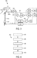
- Fig. 3 shows schematically and exemplarily another embodiment of a photoplethysmography sensor apparatus 300. Elements 3xx shown in Fig. 3 correspond to like-numbered elements 2xx in Fig. 2 .
- a synchronous detector 390 is placed before analog-to-digital converter 380, to allow rejection or suppression of further interference (such as, e.g., from 1/f noise (i.e., noise where the power spectral density (energy or power per Hz) is inversely proportional to the frequency f of the noise signal) of transimpedance amplifier 340, and external interferences not synchronous with LED light 310a).
- further interference such as, e.g., from 1/f noise (i.e., noise where the power spectral density (energy or power per Hz) is inversely proportional to the frequency f of the noise signal
- External interferences not synchronous with LED light 310a may include, e.g., external electromagnetic current such as, e.g., 50/60 Hz power line interference picked up elsewhere in the circuit (i.e. not part of the photocurrent). These interferences may hence be rejected by synchronous detector 390.
- Synchronous detector 390 preferably comprises a synchronous rectifier followed by a low pass filter. The synchronous rectifier preferably multiplies the signal with +1 or -1. Rectification is preferably synchronous with the control of LED 310, the control being effected by means of LED driver 315.
- the synchronous detector 390 may be implemented as a digital lock-in amplifier in the microcontroller.
- Fig. 4 shows schematically and exemplarily an embodiment of a photoplethysmography sensor method 400.
- a first light signal 210a, 310a is generated by a light source unit.
- a second light signal 220a, 320a is observed by a photodetector unit, wherein said second light signal 220a, 320a is indicative of an absorption of said first light signal 210a, 310a in a target 220, 320.
- a photodetector output signal is received by an ambient light compensating feedback loop (201, 301) comprising a track-and-hold unit (260, 360) and an amplifying unit (250, 350) in response to observing said second light signal 220a, 320a.
- step 440 an output signal of the track-and-hold unit 260, 360 is compared to a reference signal V R, wherein said output signal of said track-and-hold unit 260, 360 is based on said photodetector output signal.
- step 450 a compensation current is provided by the amplifying unit (250, 350) to the track-and-hold unit (260, 360) based on said comparison.
- the invention can be used in photoplethysmographic sensors, and in particular as a small and efficient photoplethysmographic front end.
- the invention can also be used in other pulse oximetry sensors, such as, e.g., SpO 2 sensors.
- a single unit or device may fulfill the functions of several items recited in the claims.
- the mere fact that certain measures are recited in mutually different dependent claims does not indicate that a combination of these measures cannot be used to advantage.
- the determinations and/or the control of the photoplethysmography sensor apparatus in accordance with the above described photoplethysmography sensor method can be implemented as program code means of a computer program and/or as dedicated hardware.
- a computer program may be stored/distributed on a suitable medium, such as an optical storage medium or a solid-state medium, supplied together with or as part of other hardware, but may also be distributed in other forms, such as via the Internet or other wired or wireless telecommunication systems.
- a suitable medium such as an optical storage medium or a solid-state medium, supplied together with or as part of other hardware, but may also be distributed in other forms, such as via the Internet or other wired or wireless telecommunication systems.
Landscapes
- Health & Medical Sciences (AREA)
- Life Sciences & Earth Sciences (AREA)
- Engineering & Computer Science (AREA)
- Cardiology (AREA)
- Public Health (AREA)
- Surgery (AREA)
- Veterinary Medicine (AREA)
- Physics & Mathematics (AREA)
- General Health & Medical Sciences (AREA)
- Biophysics (AREA)
- Pathology (AREA)
- Biomedical Technology (AREA)
- Heart & Thoracic Surgery (AREA)
- Medical Informatics (AREA)
- Molecular Biology (AREA)
- Physiology (AREA)
- Animal Behavior & Ethology (AREA)
- Signal Processing (AREA)
- Computer Vision & Pattern Recognition (AREA)
- Artificial Intelligence (AREA)
- Psychiatry (AREA)
- Investigating Or Analysing Materials By Optical Means (AREA)
- Hematology (AREA)
- Measuring Pulse, Heart Rate, Blood Pressure Or Blood Flow (AREA)
- Optical Radar Systems And Details Thereof (AREA)
Description
- The invention relates to a photoplethysmography sensor apparatus, a photoplethysmography sensor method, and a photoplethysmography sensor computer program.
- Photoplethysmography (PPG) refers to acquiring a volumetric organ measurement by optical means. Frequently, pulse oximeters are employed, which detect changes in light absorption properties of the human skin. Typically, a transmissive or reflective blood PPG sensor monitors the perfusion of blood to the dermis and subcutaneous tissue of the skin through absorption measurement at a specific wavelength. Besides light originating from blood, there is a far greater portion of light detected, which originates from tissue and ambient light.
- Photoplethysmography signals comprise a very small AC signal (the actual plethysmogram) on top of a very large (unwanted) DC offset signal. The DC offset signal comprises signals originating from skin and tissue, and from a considerable part of ambient light. Unfortunately, the amount of ambient light detected is not constant, but varies due to changing ambient light conditions and due to motion artifacts (caused, e.g., by the coupling between the photoplethysmography sensor and the skin). The temporal rate of change of detected ambient light includes frequencies in the photoplethysmography frequency band of interest. This prohibits simple frequency domain filtering, because filtering out these frequencies (in the hope of suppressing the detected ambient light) would also filter (or significantly suppress) frequencies of the photoplethysmography frequency band of interest.
- Currently known mechanisms for ambient light rejection include for example DC-restore circuits, which sample the ambient light periodically when the photoplethysmography excitation light (such as, e.g., a light-emitting diode, LED) is temporarily turned off. In a different time slot (e.g., when the LED is turned on) a sample is taken which contains both ambient and the photoplethysmography signal. By subtracting the signal with the photoplethysmography excitation light turned off from the signal with the photoplethysmography excitation light turned on, an "offset-corrected" photoplethysmography signal is obtained, which does not exhibit interference from ambient light. Typically, this sampling is done after a transimpedance amplifier (TIA) has converted and amplified the photocurrent generated by the detector into a voltage. Alternatively and/or additionally, this sampling is done completely in the digital domain after the signal has been processed by an analog-to-digital converter (ADC).
- A number of problems and disadvantages are present in conventional photoplethysmography sensors. First, the amount of ambient light detected can be considerable. This means that when designing the amplifier, a certain amount of the dynamic range available must be reserved for properly detecting the ambient light, resulting in a sub-optimal amplifier design.
- Additionally, if the subtraction of the ambient signal is done in the digital domain (i.e., after analog-to-digital conversion), then a number of ADC bits have to be reserved for the ambient light. Reserving ADC bits for the ambient light however limits the resolution available for photoplethysmography signals.
- However, if the subtraction is done directly after processing by the TIA, a sample-and-hold circuit is needed to hold the ambient value (i.e., the measurement value corresponding to the ambient light) until the next sampling period of the photoplethysmography signal. The gain accuracy of this sample-and-hold signal determines the efficacy of the compensation.
- One option to address the problems of conventional photoplethysmography sensors is to employ a factory calibration step of the sample-and-hold element. Such an additional factory calibration step however adds manufacturing costs and is thus less preferable.
-
US 7740591 discloses a plethysmography sensor. This sensor comprises an ambient light canceling circuit that receives the output of transimpedance differential amplifiers. The ambient light canceling circuit operates as follows: when timing control circuit has both the Red and IR LED's off, the ambient light is the only light the sensor has for an output. The ambient light is sampled, and the value of the signal is held in a capacitor tied to ground using a FET. When the FET is turned off, the value stored in the capacitor is used in the path of the Red and IR signal string. This stored value in the capacitor removes the error of the ambient light. -
US6381479B1 discloses a system for providing an improved DC and low frequency signal rejection in a photoplethysmographic measurement instrument. The system is used in a measurement instrument which includes at least two signal sources for transmitting light signals at least at two wavelengths through a tissue of a test subject and a detector for converting light signals transmitted through the tissue into a detector output signal. The system includes a DC restoration which removes DC and low frequency signal components from the detector output signal prior to amplification thereof so as to avoid saturating amplified output signal with the low frequency signal component. The DC restoration is configured to continuously remove low frequency signal component from the detector signal during dark intervals when the signal sources are deactivated, as well as during light intervals when one of the signal sources is activated. In one embodiment, the DC restoration is embodied in the form of a DC restoration circuit which comprises a transimpedance amplifier which receives the detector output signal and produces an amplifier output signal and an integrator feedback loop which receives the amplified output signal and produces a bias current, wherein the bias current is used to subtract DC and low frequency signal components from the detector output signal prior to amplification of the detector signal by the amplifier. - It is an object of the present invention to provide an improved photoplethysmography sensor apparatus, an improved photoplethysmography sensor method, and an improved photoplethysmography sensor computer program that overcome the problems associated with prior-art PPG sensors.
- In a first aspect of the invention, there is provided a photoplethysmography sensor apparatus comprising a light source unit configured to generate a first light signal; and a photodetector unit configured to observe a second light signal, where said second light signal is indicative of an absorption of said first light signal in a target wherein said photodetector unit is further configured to output a photodetector output signal in response to observing said second light signal. The apparatus further comprises an ambient light compensating feedback loop comprising a track-and-hold unit configured to receive a photodetector output signal. The apparatus is configured to compare an output signal of said track-and-hold unit to a reference signal and the ambient light compensating feedback loop comprises a first amplifying unit configured to provide a compensation current based on said comparison to the track-and-hold unit.
- The present invention proposes to measure a photoplethysmographic signal without ambient light interference. Ambient light signals are rejected by providing a compensation current at the input of the track-and-hold unit directly or via, for example, a transimpedance amplifier. The compensation current is preferably controlled via a closed loop, without interfering with the low duty cycle operation of the light source unit (such as, e.g., a photoplethysmography excitation LED). In other words, the present invention proposes to overcome the above-noted problems by subtracting a compensation current directly at the input of the amplifier. This current is controlled via a feedback loop which ensures that no ambient light current will enter the TIA. This eliminates the aforementioned problems. Said track-and-hold unit preferably comprises a track-and-hold circuit. By employing a track-and-hold unit, i.e., preferably a track-and-hold circuit, the present invention is well-suited for "AC kind" of ambient light, such as, e.g., artificial light and sunlight, as occurring, e.g., during running. The term "AC kind of ambient light" as used herein means that, e.g., during running, ambient light intensity varies (e.g., because the runner is swinging his/her arm periodically while running) thereby resulting in an alternating current being observed by the photodetector. The alternating current may be periodic, but that is not necessarily the case. Also step-like changes which may be caused, e.g., by a jump of the user are covered. A track-and-hold-circuit is thus preferable to, e.g., an integrate-and-hold circuit, where the light-emitting diode is pulsed with an as low as possible duty cycle. Accordingly, the ambient light is integrated during a chosen period so as to use that history for compensation during a short measurement period. It is noted that integrate-and-hold circuits do not necessarily integrate over long periods. The integration time can be chosen as short desired. However, the integration part implies a low-pass filter action, and therefore is less suited for `AC kind' of ambient light. The use of an integrating action in the negative feedback loop implies ensuring zero DC error because any non-zero DC signal will increase the error signal by integration. This cannot be achieved with a track-and-hold topology, because there the error can only become zero at infinite amplification. In the present case, it is however not necessary to have a zero DC error. Rather, ambient light is to be attenuated as much as possible to free up dynamic range. Furthermore, by providing an ambient light correcting feedback loop that is (preferably always, i.e., permanently) closed, the tracked part of the signal is always insignificantly small within the loop. As PPG signals are small (especially in reflective mode PPG sensors), ambient light levels can be relatively high. If the ambient part of the current was not continuously subtracted, an amplifier (such as, e.g., a transimpedance amplifier) receiving light from said photodetector unit would have to settle to large ambient light steps during each correction cycle. In the present configuration, this is not the case. The present embodiment thereby allows for relaxing the dynamic requirements on the PPG sensor apparatus. PPG sensors typically employ at least one amplifier. However, a PPG sensor may also use a phototransistor instead of a photodiode. A phototransistor has gain and is therefore an amplifier although it is not always explicitly visible as an amplifier if one views it as the detector. The same is true for any other photo detector with internal gain.
- In a further preferred embodiment, said first amplifying unit comprises a trans-conductance amplifier. Since said first amplifying unit comprises a trans-conductance amplifier, the difference between the track-and-hold unit's output signal and the reference signal is preferably converted to a compensation current by means of said trans-conductance amplifier. As a consequence, it is possible to subtract the compensation current already at the input of the second amplifier. In a further preferred embodiment, wherein said trans-conductance amplifier comprises a resistor and/or a voltage controlled current source. By definition trans-conductance is the reciprocal of resistance and thus has the dimension current divided by voltage, or in other words a current dependent on a voltage (i.e., a voltage controlled current source).
- In a further preferred embodiment, said photoplethysmography sensor apparatus comprises an analog-to-digital converter configured to receive the output signal from said second amplifying unit. In practice, modern PPG and SpO2 sensors have an analog front end followed by a digital processing part and thus require an ADC.
- In a further preferred embodiment, said photoplethysmography sensor apparatus further comprises a light source driver unit configured to control said light source unit. Preferably, the light source unit comprises a pulsed LED. Employing pulsed LEDs is preferable for wearable devices for battery saving reasons and ambient sampling. Employing pulsed LEDs is further preferable for medical devices with regard to ambient sampling and also because of color sequential reasons in SpO2 sensors.
- In a further preferred embodiment, said photoplethysmography sensor apparatus further comprises a synchronous detector. By employing a synchronous detector, ambient light that is not synchronous with the light signal output from said light source unit is preferably cancelled or at least suppressed.
- In a further preferred embodiment, said photoplethysmography sensor apparatus further comprises a light source driver unit configured to control said light source unit and wherein said synchronous detector is configured to operate synchronously with said light source driver unit. By having said synchronous detector and said light source driver unit operate synchronously, said photoplethysmography sensor apparatus is preferably configured such that only ambient light that is synchronous with light from said light source unit contributes a background signal to light reflected from said target. In contrast, light that is not synchronous with the light signal output from said light source unit is preferably cancelled or at least suppressed.
- In a further preferred embodiment, said photoplethysmography sensor apparatus comprises an analog-to-digital converter configured to receive the output signal from said synchronous detector. Employing an analog-to-digital converter in combination with said synchronous detector is preferable for the following reasons. A synchronous detector may be implemented in the analog or in the digital domain. Using it in the analog domain has the advantage that after the synchronous detection (which preferably includes the low pass filter) the bandwidth is limited to what is needed (for instance, approximately 15 Hz) and that all asynchronous interference has been removed. This means that a low speed high resolution ADC can be used. If SD is done in the digital domain then the bandwidth requirements are higher (depending on the LED pulse frequency) and thus AD conversion will be more expensive and/or less accurate. Furthermore, asynchronous interference is still present and needs to be considered in ADC selection. The advantage of implementing a synchronous detector in the digital domain involves an increased flexibility (because it is software and/or programmable) and, because less external components are needed. Further advantages of implementing a synchronous detector in the digital domain relate to smaller size and potentially lower power consumption.
- In a further preferred embodiment, said synchronous detector comprises a synchronous rectifier followed by a low pass filter. In a further preferred embodiment, said synchronous rectifier multiplies the signal with +1 or -1.
- In a further preferred embodiment, said photoplethysmography sensor apparatus further comprises a microcontroller configured to adjust said reference signal. Typical use-cases for adjusting the reference signal include offset compensation or level shifting, e.g. into the ADC range. The corrected output signal will "ride on/off" said reference signal. This means that with the LED off, the output of the second amplifying unit will be the reference signal. With the LED on, it will be higher or lower depending on the direction (i.e., the connection) of the photodiode. Deviation from 0V would preferably by chosen for single supply circuits (such as, e.g., battery operated devices) to level shift the signal above reference (0 V).
- In a further preferred embodiment, said photoplethysmography sensor apparatus comprises a subtractor unit. By employing a subtractor unit, the difference between said reference signal and said output signal from said track-and-hold unit can be determined.
- In a further preferred embodiment, said photodetector unit comprises a photo diode and/or transistor.
- In a further preferred embodiment, the photoplethysmography sensor apparatus further comprises a second amplifying unit for amplifying a sum of the compensation current and the photodetector output signal and for delivering an amplified signal to an input of the track and hold unit. The second amplifying unit may comprise a transimpedance amplifier. Standard layouts of transimpedance amplifiers can be found, e.g., in the book "Photodiode Amplifiers: Op Amp Solutions ", Mcgraw Hill Book Co (1995) by J. Graeme.
- In a further preferred embodiment, said photoplethysmography sensor apparatus further comprises a sample-and-hold circuit configured to store a signal output by said transimpedance amplifier. Preferably, the light source unit (such as, e.g., an LED) is driven with a low duty cycle to save battery power. This means that there is only a short period available for sampling the actual photoplethysmography signal. A sample-and-hold circuit will extend this time. However, many modern ADCs (typically referred to as sampling ADCs) already include a sample-and-hold component. Therefore, including a sample and hold circuit will provide an advantage, e.g., in case it is desired to avoid using an ADC in order to save costs and/or space by using the hardware already present in a microcontroller. There are several known possibilities to build a (low speed) ADC using a microcontroller. One possibility refers to building an SAR-ADC by using a microcontroller's analog output in combination with its voltage comparator.
- In a further preferred embodiment, said light source comprises a light emitting diode. Other types of light sources may include semiconductor lasers/VCSELs.
- In a further preferred embodiment, said synchronous detector comprises a digital lock-in amplifier. Preferably, a synchronous detector may be implemented as a synchronous rectifier (e.g., multiplying synchronously by ± 1) followed by a low-pass filter. Further preferably, a lock-in amplifier may correspond to a device that multiplies the input signal with a synchronous cosine and sine reference (i.e., an in-phase (I) and an quadrature (Q) component), followed by a low pass filter and a computation of the amplitude

- According to a second aspect of the present inventions, there is provided a photoplethysmography sensor method comprising the steps of
- generating a first light signal by a light source unit;
- observing a second light signal by a photodetector unit, wherein said second light signal is indicative of an absorption of said first light signal in a target;
- receiving, in response to observing said second light signal, a photodetector output signal by an ambient light compensating feedback loop comprising a track-and-hold unit and an amplifying unit;
- comparing an output signal of the track-and-hold unit to a reference signal, wherein said output signal of said track-and-hold unit is based on said photodetector output signal; and
- providing a compensation current by the amplifying unit to the track-and-hold unit based on said comparison.
- According to a third aspect of the present invention, there is provided a photoplethysmography sensor computer program product comprising a computer readable memory storing computer program code means for causing the photoplethysmography sensor apparatus to carry out the steps of the photoplethysmography sensor method, when the computer program is run on a computer controlling the photoplethysmography sensor apparatus.
- It shall be understood that the photoplethysmography sensor apparatus of claim 1, the photoplethysmography sensor method of claim 13 and the photoplethysmography sensor computer program of claim 14 have similar and/or identical preferred embodiments, in particular, as defined in the dependent claims.
- It shall be understood that a preferred embodiment of the present invention can also be any combination of the dependent claims or above embodiments with the respective independent claim.
- These and other aspects of the invention will be apparent from and elucidated with reference to the embodiments described hereinafter.
- In the following drawings:
-
Fig. 1 illustrates the basic principle of photoplethysmography, -
Fig. 2 shows schematically and exemplarily an embodiment of a photoplethysmography sensor apparatus, -
Fig. 3 shows schematically and exemplarily another embodiment of a photoplethysmography sensor apparatus, and -
Fig. 4 shows schematically and exemplarily an embodiment of a photoplethysmography sensor method. - The present invention relates to a photoplethysmography sensor apparatus, a photoplethysmography sensor method, and a photoplethysmography sensor computer program. It is proposed to measure a photoplethysmographic signal without ambient light interference. Ambient light signals are rejected by subtraction of a compensation current at the input of a transimpedance amplifier. The compensation current is controlled via a closed loop, without interfering with the low duty cycle operation of a photoplethysmography LED.
-
Fig. 1 illustrates the basic principle of PPG. PPG refers to acquiring a volumetric organ measurement by optical means. In example 100 shown inFig. 1 , a light-emittingdiode 110a outputs light towards ahuman finger 120a. The light is partly absorbed and partly reflected byfinger 120a. Reflected light is observed by photo diode ortransistor 130a. Further, in example 100, a light-emittingdiode 110b outputs light towards ahuman earlobe 120b. The light is partly absorbed and partly transmitted byearlobe 120b. Transmitted light is observed by photo diode ortransistor 130b. The light observed by photo diode ortransistor target -
Fig. 2 shows schematically and exemplarily an embodiment of aphotoplethysmography sensor apparatus 200.LED 210 is periodically turned on and off byLED driver 215. This saves power, but also allows sampling ambient light when theLED 210 is turned off.Light 210a emitted byLED 210 is directed towards tissue, such as, in the example shown,human wrist 220. Reflected light 220a is observed by aphoto diode 230.Reflected light 220a may additionally be filtered by an optionaloptical filter 225. Further to reflected light 220a,photo diode 230 will observe interference fromambient light 221. For the case that LED 210 is switched on,photo diode 230 will thus generate a combined current comprising an LED component IL and an ambient light component IA. - Current PPG sensors typically use a sample-and-hold circuit to 'store' an ambient sample. Thus, once a PPG signal becomes available, a correction step can be applied thereto based on the stored ambient sample. In a preferred embodiment of
photoplethysmography sensor apparatus 200, it is proposed to directly subtract a compensating current IA from the input rather than to store an ambient sample, from which a background level is derived to correct the observed signal afterwards. A closed ambient light compensatingfeedback loop 201 ensures that the output ofTIA 240 corresponds to a reference voltage VR. By maintaining this procedure, a PPG signal will thus also be compensated whenLED 210 is on. Accordingly, it is proposed to employ a track-and-hold circuit 260 to steady ambient light compensatingfeedback loop 201 when a PPG signal is taken. -
Photoplethysmography sensor apparatus 200 may be described as follows: - During a first time period, light-emitting
diode 210 is turned off. Track-and-hold circuit 260 is in "track-mode". A track-and-hold (or sample-and-hold, SHA) element stores an analog value for a certain amount of time. It thus converts a continuous time signal into a discrete time signal. An integrate-and-hold does not store the input itself, but it stores an integral of the input. (Integrate-and-hold elements are also referred to as integrating-sample-and-hold elements.) In the track-and-hold element, the output follows the input while in track mode. When switched to hold-mode, the last input level is hold. The integrate-and-hold element integrates the input signal during the integrate-mode and stores the integrated value (not equal to the input) when it is switched to hold-mode. The output of track-and-hold circuit 260 is compared to reference voltage VR (which may be, e.g., a zero voltage or some other desired DC voltage level). The difference obtained from said comparison (e.g., obtained by means of subtractor circuit 255) is subsequently converted to a compensation current by means of afirst amplifying unit 250, which may be, e.g., a trans-conductance amplifier 250. Trans-conductance amplifier 250 may be, e.g., a resistor or voltage controlled current source, but any other trans-conductance amplifying means are suitable as well. Reference voltage VR may be fixed or controlled e.g. bymicrocontroller 270. - At a second instance in time, just before light-emitting
diode 210 is turned on, track-and-hold circuit 260 is switched to a "hold-mode". In other words, the last input level is hold and the last sample "tracked" in track mode is output. The loop withinphotoplethysmography sensor apparatus 200 then subtracts the current ambient level during a subsequent time period. - During said subsequent time period, light-emitting
diode 210 is turned on. The stored ambient level is thus subtracted from the combined current IL+IA. Consequently, only the PPG signal (i.e., IL), but not the current from the interfering ambient light (i.e., IA), is amplified by asecond amplifying unit 240, which may be, e.g., a TIA. The resulting output PPG signal fromtransimpedance amplifier 240 may preferably be stored in an optional sample-and-hold circuit. Alternatively and/or additionally, the resulting output PPG signal fromtransimpedance amplifier 240 may be converted directly by analog-to-digital converter 280. - At a fourth instance in time, light-emitting
diode 210 is switched off again. The resulting setting may then be considered as the starting point for further ambient light suppression iteration by switching track-and-hold circuit 260 in the "track-mode" again and then proceeding as noted herein above. It is noted that ambient light correctingfeedback loop 201 is preferably always closed, because of the tracking part of track-and-hold circuit 260. Consequently, that part of the signal is always insignificantly small within the loop. Namely, since PPG signals are small (especially in reflective mode PPG sensors), ambient light levels can be relatively high. If ambient part IA of the current was not continuously subtracted,transimpedance amplifier 240 would have to settle to large ambient light steps during each correction cycle. In the present configuration, this is not the case. The present embodiment thereby allows for relaxing the dynamic requirements onphotoplethysmography sensor apparatus 200. -
Fig. 3 shows schematically and exemplarily another embodiment of aphotoplethysmography sensor apparatus 300. Elements 3xx shown inFig. 3 correspond to like-numbered elements 2xx inFig. 2 . In the embodiment shown inFig. 3 , asynchronous detector 390 is placed before analog-to-digital converter 380, to allow rejection or suppression of further interference (such as, e.g., from 1/f noise (i.e., noise where the power spectral density (energy or power per Hz) is inversely proportional to the frequency f of the noise signal) oftransimpedance amplifier 340, and external interferences not synchronous with LED light 310a). External interferences not synchronous withLED light 310a may include, e.g., external electromagnetic current such as, e.g., 50/60 Hz power line interference picked up elsewhere in the circuit (i.e. not part of the photocurrent). These interferences may hence be rejected bysynchronous detector 390.Synchronous detector 390 preferably comprises a synchronous rectifier followed by a low pass filter. The synchronous rectifier preferably multiplies the signal with +1 or -1. Rectification is preferably synchronous with the control ofLED 310, the control being effected by means ofLED driver 315. - In a further preferred embodiment, the
synchronous detector 390 may be implemented as a digital lock-in amplifier in the microcontroller. -
Fig. 4 shows schematically and exemplarily an embodiment of aphotoplethysmography sensor method 400. - In
step 410, afirst light signal - In
step 420, asecond light signal second light signal first light signal target - In
step 430, a photodetector output signal is received by an ambient light compensating feedback loop (201, 301) comprising a track-and-hold unit (260, 360) and an amplifying unit (250, 350) in response to observing saidsecond light signal - In
step 440, an output signal of the track-and-hold unit hold unit - In
step 450, a compensation current is provided by the amplifying unit (250, 350) to the track-and-hold unit (260, 360) based on said comparison. - The invention can be used in photoplethysmographic sensors, and in particular as a small and efficient photoplethysmographic front end. The invention can also be used in other pulse oximetry sensors, such as, e.g., SpO2 sensors.
- Other variations to the disclosed embodiments can be understood and effected by those skilled in the art in practicing the claimed invention, from a study of the drawings, the disclosure, and the appended claims.
- In the claims, the word "comprising" does not exclude other elements or steps, and the indefinite article "a" or "an" does not exclude a plurality.
- A single unit or device may fulfill the functions of several items recited in the claims. The mere fact that certain measures are recited in mutually different dependent claims does not indicate that a combination of these measures cannot be used to advantage.
- The determinations and/or the control of the photoplethysmography sensor apparatus in accordance with the above described photoplethysmography sensor method can be implemented as program code means of a computer program and/or as dedicated hardware.
- A computer program may be stored/distributed on a suitable medium, such as an optical storage medium or a solid-state medium, supplied together with or as part of other hardware, but may also be distributed in other forms, such as via the Internet or other wired or wireless telecommunication systems.
- Any reference signs in the claims should not be construed as limiting the scope.
Claims (14)
- A photoplethysmography sensor apparatus (200, 300) comprising:- a light source unit (210, 310) configured to generate a first light signal (210a, 310a);- a photodetector unit (230, 330) configured to observe a second light signal (220a, 320a), where said second light signal (220a, 320a) is indicative of an absorption of said first light signal (210a, 310a) in a target (220, 320), wherein said photodetector unit (230, 330) is further configured to output a photodetector output signal in response to observing said second light signal (220a, 320a); and- an ambient light compensating feedback loop (201, 301) comprising a track-and-hold unit (260, 360) configured to receive said photodetector output signal;
wherein said photoplethysmography sensor apparatus (200, 300) is configured to compare an output signal of said track-and-hold unit (260, 360) to a reference signal (VR), and wherein said ambient light compensating feedback loop (201, 301) comprises a first amplifying unit (250, 350) configured to provide a compensation current based on said comparison to the track-and-hold unit (260, 360). - The photoplethysmography sensor apparatus (200, 300) of claim 1, further comprising a second amplifying unit (240, 340) for amplifying a sum of the compensation current and the photodetector output signal and for delivering an amplified signal to an input of the track and hold unit (260).
- The photoplethysmography sensor apparatus (200, 300) of claim 2, wherein said second amplifying unit (240, 340) comprises a transimpedance amplifier.
- The photoplethysmography sensor apparatus (200, 300) of claim 1, wherein said first amplifying unit (250, 350) comprises a trans-conductance amplifier, wherein said trans-conductance amplifier (250, 350) comprises a resistor and/or a voltage controlled current source.
- The photoplethysmography sensor apparatus (200) of claim 2, wherein said photoplethysmography sensor apparatus (200) comprises an analog-to-digital converter (280) configured to receive an output signal from said second amplifying unit (240).
- The photoplethysmography sensor apparatus (200, 300) of claim 1, wherein said photoplethysmography sensor apparatus (200, 300) further comprises a light source driver unit (215, 315) configured to control said light source unit (210, 310).
- The photoplethysmography sensor apparatus (300) of claim 1, wherein said photoplethysmography sensor apparatus (300) further comprises a synchronous detector (390).
- The photoplethysmography sensor apparatus (300) of claim 7, wherein said photoplethysmography sensor apparatus (300) further comprises a light source driver unit (315) configured to control said light source unit (310) and wherein said synchronous detector (390) is configured to operate synchronously with said light source driver unit (315).
- The photoplethysmography sensor apparatus (300) of claim 7, wherein said photoplethysmography sensor apparatus (300) comprises an analog-to-digital converter (380) configured to receive the output signal from said synchronous detector (390).
- The photoplethysmography sensor apparatus (200, 300) of claim 7, wherein said synchronous detector (390) comprises a synchronous rectifier followed by a low pass filter.
- The photoplethysmography sensor apparatus (200, 300) of claim 10, wherein said synchronous rectifier multiplies the signal with +1 or -1.
- The photoplethysmography sensor apparatus (200, 300) of claim 1, wherein said photoplethysmography sensor apparatus (200, 300) further comprises a microcontroller (270, 370) configured to adjust said reference signal (VR).
- A photoplethysmography sensor method (400) comprising the steps of:- generating (410) a first light signal (210a, 310a) by a light source unit;- observing (420) a second light signal (220a, 320a) by a photodetector unit, wherein said second light signal (220a, 320a) is indicative of an absorption of said first light signal (210a, 310a) in a target (220, 320);- receiving (430), in response to observing said second light signal (220a, 320a), a photodetector output signal by an ambient light compensating feedback loop (201, 301) comprising a track-and-hold unit (260, 360) and an amplifying unit (250, 350);- comparing (440) an output signal of the track-and-hold unit (260, 360) to a reference signal (VR), wherein said output signal of said track-and-hold unit (260, 360) is based on said photodetector output signal; and- providing (450) a compensation current by the amplifying unit (250, 350) to the track-and-hold unit (260, 360) based on said comparison.
- A photoplethysmography sensor computer program product comprising a computer readable memory storing computer program code means for causing the photoplethysmography sensor apparatus (200, 300) as defined in claim 1 to carry out the steps of the photoplethysmography sensor method (400) as defined in claim 13, when the computer program is run on a computer controlling the photoplethysmography sensor apparatus (200, 300).
Priority Applications (1)
| Application Number | Priority Date | Filing Date | Title |
|---|---|---|---|
| EP15731553.2A EP3016582B1 (en) | 2014-06-30 | 2015-06-19 | Photoplethysmography sensor apparatus and method |
Applications Claiming Priority (3)
| Application Number | Priority Date | Filing Date | Title |
|---|---|---|---|
| EP14174974 | 2014-06-30 | ||
| PCT/EP2015/063858 WO2016000986A1 (en) | 2014-06-30 | 2015-06-19 | Photoplethysmography sensor apparatus and method |
| EP15731553.2A EP3016582B1 (en) | 2014-06-30 | 2015-06-19 | Photoplethysmography sensor apparatus and method |
Publications (2)
| Publication Number | Publication Date |
|---|---|
| EP3016582A1 EP3016582A1 (en) | 2016-05-11 |
| EP3016582B1 true EP3016582B1 (en) | 2017-01-11 |
Family
ID=51059313
Family Applications (1)
| Application Number | Title | Priority Date | Filing Date |
|---|---|---|---|
| EP15731553.2A Active EP3016582B1 (en) | 2014-06-30 | 2015-06-19 | Photoplethysmography sensor apparatus and method |
Country Status (8)
| Country | Link |
|---|---|
| US (1) | US9775528B2 (en) |
| EP (1) | EP3016582B1 (en) |
| JP (1) | JP6455994B2 (en) |
| CN (1) | CN105491943B (en) |
| ES (1) | ES2621429T3 (en) |
| PL (1) | PL3016582T3 (en) |
| RU (1) | RU2653834C2 (en) |
| WO (1) | WO2016000986A1 (en) |
Families Citing this family (36)
| Publication number | Priority date | Publication date | Assignee | Title |
|---|---|---|---|---|
| JP6455994B2 (en) * | 2014-06-30 | 2019-01-23 | コーニンクレッカ フィリップス エヌ ヴェKoninklijke Philips N.V. | Photoplethysmographic sensor device and method |
| US11262354B2 (en) | 2014-10-20 | 2022-03-01 | Boston Scientific Scimed, Inc. | Disposable sensor elements, systems, and related methods |
| US10004408B2 (en) | 2014-12-03 | 2018-06-26 | Rethink Medical, Inc. | Methods and systems for detecting physiology for monitoring cardiac health |
| US10568530B2 (en) | 2015-06-27 | 2020-02-25 | Intel Corporation | Apparatus and method for tracking and cancelling DC offset to acquire small AC signal |
| US10541652B2 (en) | 2015-06-27 | 2020-01-21 | Intel Corporation | Apparatus and method for filter settling calibration to improve speed of tracking and cancelling of DC offset |
| US9880266B2 (en) | 2015-07-31 | 2018-01-30 | Avago Technologies General Ip (Singapore) Pte. Ltd. | Measurement system incorporating ambient light component nullification |
| US10203400B2 (en) | 2015-07-31 | 2019-02-12 | Avago Technologies International Sales Pte. Limited | Optical measurement system incorporating ambient light component nullification |
| US10231632B2 (en) | 2016-02-22 | 2019-03-19 | Intel Corporation | Apparatus and method for tracking and cancelling DC offset to acquire small AC signal using dual feedback loops |
| US10362994B2 (en) * | 2016-02-29 | 2019-07-30 | Texas Instruments Incorporated | Bio-sensing device with ambient light cancellation |
| US10045721B2 (en) | 2016-03-30 | 2018-08-14 | Intel Corporation | Apparatus, system, and method for automatic power reduction in photoplethysmography and pulse oximetry systems |
| CN105910632B (en) * | 2016-04-21 | 2018-10-26 | 矽力杰半导体技术(杭州)有限公司 | Optoelectronic detecting device and integrated circuit |
| US10433739B2 (en) * | 2016-04-29 | 2019-10-08 | Fitbit, Inc. | Multi-channel photoplethysmography sensor |
| CN109310326B (en) | 2016-06-15 | 2022-03-01 | 波士顿科学国际有限公司 | Gas sampling conduit |
| CN109788919B (en) * | 2016-09-29 | 2022-03-22 | 皇家飞利浦有限公司 | Optical vital sign sensor |
| CN109862829A (en) | 2016-10-21 | 2019-06-07 | 波士顿科学国际有限公司 | Gas sampling assembly |
| EP3361232A1 (en) * | 2017-02-09 | 2018-08-15 | Koninklijke Philips N.V. | Optical particle sensor and sensing method |
| TW201838584A (en) | 2017-04-18 | 2018-11-01 | 原相科技股份有限公司 | Electronic apparatus and method capable of reducing or avoiding offset interference and accurately measuring physiological characteristics of user |
| CN113558596A (en) * | 2017-04-27 | 2021-10-29 | 原相科技股份有限公司 | Method for measuring physiological characteristics |
| US10770182B2 (en) | 2017-05-19 | 2020-09-08 | Boston Scientific Scimed, Inc. | Systems and methods for assessing the health status of a patient |
| US10852264B2 (en) | 2017-07-18 | 2020-12-01 | Boston Scientific Scimed, Inc. | Systems and methods for analyte sensing in physiological gas samples |
| ES2927580T3 (en) | 2018-02-20 | 2022-11-08 | Univ Minnesota | Mask and breath sampling system |
| CN109091115B (en) * | 2018-09-17 | 2023-08-08 | 电子科技大学 | Direct current suppression device applied to physiological signal acquisition |
| EP3867639A1 (en) | 2018-10-19 | 2021-08-25 | Regents of the University of Minnesota | Systems and methods for detecting a brain condition |
| EP3861329A1 (en) | 2018-11-27 | 2021-08-11 | Boston Scientific Scimed Inc. | Systems and methods for detecting a health condition |
| EP3899515B1 (en) | 2018-12-18 | 2023-01-25 | Boston Scientific Scimed Inc. | Systems and methods for measuring kinetic response of chemical sensor elements comprising graphene varactors |
| US11112303B2 (en) * | 2019-02-15 | 2021-09-07 | Semiconductor Components Industries, Llc | Measurement circuit and method therefor |
| US11607146B2 (en) | 2019-05-30 | 2023-03-21 | Welch Allyn, Inc. | Photoplethysmography device with thermal trapping and/or warming capability and associated methods |
| CN110338776B (en) * | 2019-07-11 | 2022-04-01 | 无锡金童科技有限公司 | PPG signal acquisition chip and device based on CMOS integrated circuit technology |
| CN114651178A (en) | 2019-09-10 | 2022-06-21 | 波士顿科学国际有限公司 | Gas measurement device and method |
| CN110604559B (en) | 2019-10-25 | 2023-11-28 | 深圳市汇顶科技股份有限公司 | Ambient light signal adjusting method, chip and electronic device |
| WO2021097755A1 (en) * | 2019-11-21 | 2021-05-27 | 深圳市汇顶科技股份有限公司 | Biological feature detection method, biological feature detection device and electronic device |
| WO2021102627A1 (en) * | 2019-11-25 | 2021-06-03 | 深圳市汇顶科技股份有限公司 | Biological characteristic detection method, biological characteristic detection device, and electronic device |
| JP2023539401A (en) * | 2020-05-29 | 2023-09-14 | アトコア メディカル ピーティーワイ リミテッド | Wearable device with plethysmogram sensor |
| KR20220007367A (en) * | 2020-07-10 | 2022-01-18 | 삼성전자주식회사 | Photoplethysmography(PPG) sensor and semiconductor device comprising the PPG sensor |
| CN114052696B (en) * | 2021-11-19 | 2024-03-26 | 恒玄科技(上海)股份有限公司 | PPG signal detection method, component and wearable device |
| CN114384314A (en) * | 2021-12-31 | 2022-04-22 | 芯海科技(深圳)股份有限公司 | Signal detection circuit, method, integrated circuit, detection device and electronic equipment |
Family Cites Families (20)
| Publication number | Priority date | Publication date | Assignee | Title |
|---|---|---|---|---|
| US4258719A (en) * | 1978-12-04 | 1981-03-31 | Hughes Aircraft Company | Heart rate measurement system |
| US4353152A (en) | 1980-02-21 | 1982-10-12 | Novatec, Inc. | Pulse rate monitor |
| US4781195A (en) * | 1987-12-02 | 1988-11-01 | The Boc Group, Inc. | Blood monitoring apparatus and methods with amplifier input dark current correction |
| US5177565A (en) | 1991-02-11 | 1993-01-05 | United Medical Manufacturing Company | Reflectance measurement apparatus with noise reduction circuitry |
| US5853372A (en) | 1995-08-14 | 1998-12-29 | Advanced Body Metrics Corporation | Near infra-red signal processing system |
| US5954644A (en) | 1997-03-24 | 1999-09-21 | Ohmeda Inc. | Method for ambient light subtraction in a photoplethysmographic measurement instrument |
| JP3208538B2 (en) * | 1998-11-10 | 2001-09-17 | 山越 憲一 | Photoplethysmograph |
| US6381479B1 (en) * | 1999-12-17 | 2002-04-30 | Date-Ohmeda, Inc. | Pulse oximeter with improved DC and low frequency rejection |
| WO2005009221A2 (en) | 2003-07-21 | 2005-02-03 | The Titan Corporation | Data acquisition system for pulse oximeters |
| US7740591B1 (en) * | 2003-12-01 | 2010-06-22 | Ric Investments, Llc | Apparatus and method for monitoring pressure related changes in the extra-thoracic arterial circulatory system |
| US7190985B2 (en) | 2004-02-25 | 2007-03-13 | Nellcor Puritan Bennett Inc. | Oximeter ambient light cancellation |
| NZ538082A (en) | 2005-02-04 | 2007-03-30 | Senscio Ltd | Ambient light auto-zero circuit for photo-optical physiological monitoring equipment |
| WO2009136341A2 (en) * | 2008-05-09 | 2009-11-12 | Philips Intellectual Property & Standards Gmbh | Contactless respiration monitoring of a patient and optical sensor for a photoplethysmography measurement |
| JP5298662B2 (en) * | 2008-06-25 | 2013-09-25 | 富士通株式会社 | Photoelectric pulse wave measuring apparatus and photoelectric pulse wave measuring program |
| US9596999B2 (en) * | 2009-06-17 | 2017-03-21 | Sotera Wireless, Inc. | Body-worn pulse oximeter |
| CN102686151B (en) * | 2009-12-21 | 2015-08-19 | 皇家飞利浦电子股份有限公司 | For the treatment of the method and apparatus of photoplethysmo graph signal |
| RU99946U1 (en) * | 2010-06-09 | 2010-12-10 | Государственное образовательное учреждение высшего профессиоанльного образования Ижевский государственный технический университет | DEVICE FOR PHOTOPLETISMOGRAPHY |
| WO2013077808A1 (en) | 2011-11-25 | 2013-05-30 | Nitto Denko Corporation | A method of obtaining a correction factor and a calibration device facilitating performance of said method |
| CN103006238B (en) * | 2013-01-07 | 2014-11-26 | 天津大学 | Method for measuring degree of blood oxygen saturation |
| JP6455994B2 (en) * | 2014-06-30 | 2019-01-23 | コーニンクレッカ フィリップス エヌ ヴェKoninklijke Philips N.V. | Photoplethysmographic sensor device and method |
-
2015
- 2015-06-19 JP JP2016515947A patent/JP6455994B2/en not_active Expired - Fee Related
- 2015-06-19 RU RU2016102719A patent/RU2653834C2/en not_active IP Right Cessation
- 2015-06-19 ES ES15731553.2T patent/ES2621429T3/en active Active
- 2015-06-19 WO PCT/EP2015/063858 patent/WO2016000986A1/en active Application Filing
- 2015-06-19 PL PL15731553T patent/PL3016582T3/en unknown
- 2015-06-19 EP EP15731553.2A patent/EP3016582B1/en active Active
- 2015-06-19 US US14/912,418 patent/US9775528B2/en active Active
- 2015-06-19 CN CN201580001728.9A patent/CN105491943B/en active Active
Non-Patent Citations (1)
| Title |
|---|
| None * |
Also Published As
| Publication number | Publication date |
|---|---|
| US9775528B2 (en) | 2017-10-03 |
| RU2016102719A (en) | 2017-08-02 |
| ES2621429T3 (en) | 2017-07-04 |
| JP6455994B2 (en) | 2019-01-23 |
| RU2653834C2 (en) | 2018-05-14 |
| JP2016529932A (en) | 2016-09-29 |
| US20170042435A1 (en) | 2017-02-16 |
| WO2016000986A1 (en) | 2016-01-07 |
| CN105491943A (en) | 2016-04-13 |
| CN105491943B (en) | 2018-11-13 |
| EP3016582A1 (en) | 2016-05-11 |
| PL3016582T3 (en) | 2017-09-29 |
Similar Documents
| Publication | Publication Date | Title |
|---|---|---|
| EP3016582B1 (en) | Photoplethysmography sensor apparatus and method | |
| US10433738B2 (en) | Method and apparatus for optical sensing of tissue variation at increased accuracy | |
| US10362994B2 (en) | Bio-sensing device with ambient light cancellation | |
| EP2861131B1 (en) | Photoplethysmographic device and method. | |
| US11344234B2 (en) | Circuit arrangement for an optical monitoring system and method for optical monitoring | |
| JP6020719B2 (en) | Biosensor | |
| JP2003153881A (en) | Blood component measuring instrument | |
| US20200037901A1 (en) | Circuit arrangement for an optical monitoring system and method for optical monitoring | |
| US20130021018A1 (en) | Ambient Noise Cancellation in Pulsed Input System | |
| RU2696422C2 (en) | Optical analysis system and method | |
| WO2015159187A1 (en) | Low power pulse oximeter and a method thereof | |
| Caizzone et al. | Ac/dc ratio enhancement in photoplethysmography using a pinned photodiode | |
| JP2007105133A (en) | Light receiving device | |
| US10588522B2 (en) | Biological sensor | |
| JP4962234B2 (en) | Pulse oximeter | |
| US9936885B1 (en) | Apparatus for ambient noise cancellation in PPG sensors |
Legal Events
| Date | Code | Title | Description |
|---|---|---|---|
| PUAI | Public reference made under article 153(3) epc to a published international application that has entered the european phase |
Free format text: ORIGINAL CODE: 0009012 |
|
| 17P | Request for examination filed |
Effective date: 20160203 |
|
| AK | Designated contracting states |
Kind code of ref document: A1 Designated state(s): AL AT BE BG CH CY CZ DE DK EE ES FI FR GB GR HR HU IE IS IT LI LT LU LV MC MK MT NL NO PL PT RO RS SE SI SK SM TR |
|
| AX | Request for extension of the european patent |
Extension state: BA ME |
|
| GRAP | Despatch of communication of intention to grant a patent |
Free format text: ORIGINAL CODE: EPIDOSNIGR1 |
|
| INTG | Intention to grant announced |
Effective date: 20160805 |
|
| GRAS | Grant fee paid |
Free format text: ORIGINAL CODE: EPIDOSNIGR3 |
|
| GRAA | (expected) grant |
Free format text: ORIGINAL CODE: 0009210 |
|
| DAV | Request for validation of the european patent (deleted) | ||
| DAX | Request for extension of the european patent (deleted) | ||
| AK | Designated contracting states |
Kind code of ref document: B1 Designated state(s): AL AT BE BG CH CY CZ DE DK EE ES FI FR GB GR HR HU IE IS IT LI LT LU LV MC MK MT NL NO PL PT RO RS SE SI SK SM TR |
|
| REG | Reference to a national code |
Ref country code: GB Ref legal event code: FG4D |
|
| REG | Reference to a national code |
Ref country code: CH Ref legal event code: EP |
|
| REG | Reference to a national code |
Ref country code: AT Ref legal event code: REF Ref document number: 860499 Country of ref document: AT Kind code of ref document: T Effective date: 20170115 |
|
| REG | Reference to a national code |
Ref country code: IE Ref legal event code: FG4D |
|
| REG | Reference to a national code |
Ref country code: DE Ref legal event code: R096 Ref document number: 602015001288 Country of ref document: DE |
|
| REG | Reference to a national code |
Ref country code: NL Ref legal event code: FP |
|
| REG | Reference to a national code |
Ref country code: LT Ref legal event code: MG4D |
|
| REG | Reference to a national code |
Ref country code: AT Ref legal event code: MK05 Ref document number: 860499 Country of ref document: AT Kind code of ref document: T Effective date: 20170111 |
|
| REG | Reference to a national code |
Ref country code: FR Ref legal event code: PLFP Year of fee payment: 3 |
|
| REG | Reference to a national code |
Ref country code: ES Ref legal event code: FG2A Ref document number: 2621429 Country of ref document: ES Kind code of ref document: T3 Effective date: 20170704 |
|
| PG25 | Lapsed in a contracting state [announced via postgrant information from national office to epo] |
Ref country code: GR Free format text: LAPSE BECAUSE OF FAILURE TO SUBMIT A TRANSLATION OF THE DESCRIPTION OR TO PAY THE FEE WITHIN THE PRESCRIBED TIME-LIMIT Effective date: 20170412 Ref country code: HR Free format text: LAPSE BECAUSE OF FAILURE TO SUBMIT A TRANSLATION OF THE DESCRIPTION OR TO PAY THE FEE WITHIN THE PRESCRIBED TIME-LIMIT Effective date: 20170111 Ref country code: IS Free format text: LAPSE BECAUSE OF FAILURE TO SUBMIT A TRANSLATION OF THE DESCRIPTION OR TO PAY THE FEE WITHIN THE PRESCRIBED TIME-LIMIT Effective date: 20170511 Ref country code: NO Free format text: LAPSE BECAUSE OF FAILURE TO SUBMIT A TRANSLATION OF THE DESCRIPTION OR TO PAY THE FEE WITHIN THE PRESCRIBED TIME-LIMIT Effective date: 20170411 Ref country code: FI Free format text: LAPSE BECAUSE OF FAILURE TO SUBMIT A TRANSLATION OF THE DESCRIPTION OR TO PAY THE FEE WITHIN THE PRESCRIBED TIME-LIMIT Effective date: 20170111 Ref country code: LT Free format text: LAPSE BECAUSE OF FAILURE TO SUBMIT A TRANSLATION OF THE DESCRIPTION OR TO PAY THE FEE WITHIN THE PRESCRIBED TIME-LIMIT Effective date: 20170111 |
|
| PG25 | Lapsed in a contracting state [announced via postgrant information from national office to epo] |
Ref country code: LV Free format text: LAPSE BECAUSE OF FAILURE TO SUBMIT A TRANSLATION OF THE DESCRIPTION OR TO PAY THE FEE WITHIN THE PRESCRIBED TIME-LIMIT Effective date: 20170111 Ref country code: AT Free format text: LAPSE BECAUSE OF FAILURE TO SUBMIT A TRANSLATION OF THE DESCRIPTION OR TO PAY THE FEE WITHIN THE PRESCRIBED TIME-LIMIT Effective date: 20170111 Ref country code: RS Free format text: LAPSE BECAUSE OF FAILURE TO SUBMIT A TRANSLATION OF THE DESCRIPTION OR TO PAY THE FEE WITHIN THE PRESCRIBED TIME-LIMIT Effective date: 20170111 Ref country code: SE Free format text: LAPSE BECAUSE OF FAILURE TO SUBMIT A TRANSLATION OF THE DESCRIPTION OR TO PAY THE FEE WITHIN THE PRESCRIBED TIME-LIMIT Effective date: 20170111 Ref country code: PT Free format text: LAPSE BECAUSE OF FAILURE TO SUBMIT A TRANSLATION OF THE DESCRIPTION OR TO PAY THE FEE WITHIN THE PRESCRIBED TIME-LIMIT Effective date: 20170511 Ref country code: BG Free format text: LAPSE BECAUSE OF FAILURE TO SUBMIT A TRANSLATION OF THE DESCRIPTION OR TO PAY THE FEE WITHIN THE PRESCRIBED TIME-LIMIT Effective date: 20170411 |
|
| REG | Reference to a national code |
Ref country code: DE Ref legal event code: R097 Ref document number: 602015001288 Country of ref document: DE |
|
| PG25 | Lapsed in a contracting state [announced via postgrant information from national office to epo] |
Ref country code: SK Free format text: LAPSE BECAUSE OF FAILURE TO SUBMIT A TRANSLATION OF THE DESCRIPTION OR TO PAY THE FEE WITHIN THE PRESCRIBED TIME-LIMIT Effective date: 20170111 Ref country code: RO Free format text: LAPSE BECAUSE OF FAILURE TO SUBMIT A TRANSLATION OF THE DESCRIPTION OR TO PAY THE FEE WITHIN THE PRESCRIBED TIME-LIMIT Effective date: 20170111 Ref country code: EE Free format text: LAPSE BECAUSE OF FAILURE TO SUBMIT A TRANSLATION OF THE DESCRIPTION OR TO PAY THE FEE WITHIN THE PRESCRIBED TIME-LIMIT Effective date: 20170111 Ref country code: CZ Free format text: LAPSE BECAUSE OF FAILURE TO SUBMIT A TRANSLATION OF THE DESCRIPTION OR TO PAY THE FEE WITHIN THE PRESCRIBED TIME-LIMIT Effective date: 20170111 |
|
| PLBE | No opposition filed within time limit |
Free format text: ORIGINAL CODE: 0009261 |
|
| STAA | Information on the status of an ep patent application or granted ep patent |
Free format text: STATUS: NO OPPOSITION FILED WITHIN TIME LIMIT |
|
| PG25 | Lapsed in a contracting state [announced via postgrant information from national office to epo] |
Ref country code: SM Free format text: LAPSE BECAUSE OF FAILURE TO SUBMIT A TRANSLATION OF THE DESCRIPTION OR TO PAY THE FEE WITHIN THE PRESCRIBED TIME-LIMIT Effective date: 20170111 Ref country code: DK Free format text: LAPSE BECAUSE OF FAILURE TO SUBMIT A TRANSLATION OF THE DESCRIPTION OR TO PAY THE FEE WITHIN THE PRESCRIBED TIME-LIMIT Effective date: 20170111 |
|
| 26N | No opposition filed |
Effective date: 20171012 |
|
| PG25 | Lapsed in a contracting state [announced via postgrant information from national office to epo] |
Ref country code: MC Free format text: LAPSE BECAUSE OF FAILURE TO SUBMIT A TRANSLATION OF THE DESCRIPTION OR TO PAY THE FEE WITHIN THE PRESCRIBED TIME-LIMIT Effective date: 20170111 |
|
| PG25 | Lapsed in a contracting state [announced via postgrant information from national office to epo] |
Ref country code: SI Free format text: LAPSE BECAUSE OF FAILURE TO SUBMIT A TRANSLATION OF THE DESCRIPTION OR TO PAY THE FEE WITHIN THE PRESCRIBED TIME-LIMIT Effective date: 20170111 |
|
| REG | Reference to a national code |
Ref country code: IE Ref legal event code: MM4A |
|
| PG25 | Lapsed in a contracting state [announced via postgrant information from national office to epo] |
Ref country code: IE Free format text: LAPSE BECAUSE OF NON-PAYMENT OF DUE FEES Effective date: 20170619 Ref country code: LU Free format text: LAPSE BECAUSE OF NON-PAYMENT OF DUE FEES Effective date: 20170619 |
|
| REG | Reference to a national code |
Ref country code: BE Ref legal event code: MM Effective date: 20170630 |
|
| REG | Reference to a national code |
Ref country code: FR Ref legal event code: PLFP Year of fee payment: 4 |
|
| PG25 | Lapsed in a contracting state [announced via postgrant information from national office to epo] |
Ref country code: BE Free format text: LAPSE BECAUSE OF NON-PAYMENT OF DUE FEES Effective date: 20170630 |
|
| PG25 | Lapsed in a contracting state [announced via postgrant information from national office to epo] |
Ref country code: MT Free format text: LAPSE BECAUSE OF NON-PAYMENT OF DUE FEES Effective date: 20170619 |
|
| REG | Reference to a national code |
Ref country code: CH Ref legal event code: PL |
|
| PG25 | Lapsed in a contracting state [announced via postgrant information from national office to epo] |
Ref country code: CH Free format text: LAPSE BECAUSE OF NON-PAYMENT OF DUE FEES Effective date: 20180630 Ref country code: LI Free format text: LAPSE BECAUSE OF NON-PAYMENT OF DUE FEES Effective date: 20180630 |
|
| PG25 | Lapsed in a contracting state [announced via postgrant information from national office to epo] |
Ref country code: HU Free format text: LAPSE BECAUSE OF FAILURE TO SUBMIT A TRANSLATION OF THE DESCRIPTION OR TO PAY THE FEE WITHIN THE PRESCRIBED TIME-LIMIT; INVALID AB INITIO Effective date: 20150619 |
|
| PGFP | Annual fee paid to national office [announced via postgrant information from national office to epo] |
Ref country code: NL Payment date: 20190626 Year of fee payment: 5 Ref country code: IT Payment date: 20190624 Year of fee payment: 5 Ref country code: PL Payment date: 20190613 Year of fee payment: 5 |
|
| PGFP | Annual fee paid to national office [announced via postgrant information from national office to epo] |
Ref country code: BE Payment date: 20190625 Year of fee payment: 5 |
|
| PG25 | Lapsed in a contracting state [announced via postgrant information from national office to epo] |
Ref country code: CY Free format text: LAPSE BECAUSE OF FAILURE TO SUBMIT A TRANSLATION OF THE DESCRIPTION OR TO PAY THE FEE WITHIN THE PRESCRIBED TIME-LIMIT Effective date: 20170111 |
|
| PGFP | Annual fee paid to national office [announced via postgrant information from national office to epo] |
Ref country code: ES Payment date: 20190725 Year of fee payment: 5 |
|
| PG25 | Lapsed in a contracting state [announced via postgrant information from national office to epo] |
Ref country code: MK Free format text: LAPSE BECAUSE OF FAILURE TO SUBMIT A TRANSLATION OF THE DESCRIPTION OR TO PAY THE FEE WITHIN THE PRESCRIBED TIME-LIMIT Effective date: 20170111 |
|
| PG25 | Lapsed in a contracting state [announced via postgrant information from national office to epo] |
Ref country code: AL Free format text: LAPSE BECAUSE OF FAILURE TO SUBMIT A TRANSLATION OF THE DESCRIPTION OR TO PAY THE FEE WITHIN THE PRESCRIBED TIME-LIMIT Effective date: 20170111 |
|
| REG | Reference to a national code |
Ref country code: NL Ref legal event code: MM Effective date: 20200701 |
|
| PG25 | Lapsed in a contracting state [announced via postgrant information from national office to epo] |
Ref country code: NL Free format text: LAPSE BECAUSE OF NON-PAYMENT OF DUE FEES Effective date: 20200701 |
|
| PG25 | Lapsed in a contracting state [announced via postgrant information from national office to epo] |
Ref country code: IT Free format text: LAPSE BECAUSE OF NON-PAYMENT OF DUE FEES Effective date: 20200619 |
|
| REG | Reference to a national code |
Ref country code: ES Ref legal event code: FD2A Effective date: 20211102 |
|
| PG25 | Lapsed in a contracting state [announced via postgrant information from national office to epo] |
Ref country code: ES Free format text: LAPSE BECAUSE OF NON-PAYMENT OF DUE FEES Effective date: 20200620 |
|
| PG25 | Lapsed in a contracting state [announced via postgrant information from national office to epo] |
Ref country code: TR Free format text: LAPSE BECAUSE OF NON-PAYMENT OF DUE FEES Effective date: 20200619 |
|
| PG25 | Lapsed in a contracting state [announced via postgrant information from national office to epo] |
Ref country code: PL Free format text: LAPSE BECAUSE OF NON-PAYMENT OF DUE FEES Effective date: 20200619 |
|
| PGFP | Annual fee paid to national office [announced via postgrant information from national office to epo] |
Ref country code: FR Payment date: 20230622 Year of fee payment: 9 Ref country code: DE Payment date: 20230627 Year of fee payment: 9 |
|
| PGFP | Annual fee paid to national office [announced via postgrant information from national office to epo] |
Ref country code: GB Payment date: 20230620 Year of fee payment: 9 |