EP3014367B1 - Method and video communication device for transmitting video to a remote user - Google Patents
Method and video communication device for transmitting video to a remote user Download PDFInfo
- Publication number
- EP3014367B1 EP3014367B1 EP13732486.9A EP13732486A EP3014367B1 EP 3014367 B1 EP3014367 B1 EP 3014367B1 EP 13732486 A EP13732486 A EP 13732486A EP 3014367 B1 EP3014367 B1 EP 3014367B1
- Authority
- EP
- European Patent Office
- Prior art keywords
- communication device
- video
- video communication
- camera
- location
- Prior art date
- Legal status (The legal status is an assumption and is not a legal conclusion. Google has not performed a legal analysis and makes no representation as to the accuracy of the status listed.)
- Active
Links
Images


Classifications
-
- H—ELECTRICITY
- H04—ELECTRIC COMMUNICATION TECHNIQUE
- H04N—PICTORIAL COMMUNICATION, e.g. TELEVISION
- H04N13/00—Stereoscopic video systems; Multi-view video systems; Details thereof
- H04N13/10—Processing, recording or transmission of stereoscopic or multi-view image signals
- H04N13/194—Transmission of image signals
-
- H—ELECTRICITY
- H04—ELECTRIC COMMUNICATION TECHNIQUE
- H04N—PICTORIAL COMMUNICATION, e.g. TELEVISION
- H04N21/00—Selective content distribution, e.g. interactive television or video on demand [VOD]
- H04N21/40—Client devices specifically adapted for the reception of or interaction with content, e.g. set-top-box [STB]; Operations thereof
- H04N21/41—Structure of client; Structure of client peripherals
- H04N21/422—Input-only peripherals, i.e. input devices connected to specially adapted client devices, e.g. global positioning system [GPS]
- H04N21/42202—Input-only peripherals, i.e. input devices connected to specially adapted client devices, e.g. global positioning system [GPS] environmental sensors, e.g. for detecting temperature, luminosity, pressure, earthquakes
-
- H—ELECTRICITY
- H04—ELECTRIC COMMUNICATION TECHNIQUE
- H04N—PICTORIAL COMMUNICATION, e.g. TELEVISION
- H04N21/00—Selective content distribution, e.g. interactive television or video on demand [VOD]
- H04N21/40—Client devices specifically adapted for the reception of or interaction with content, e.g. set-top-box [STB]; Operations thereof
- H04N21/41—Structure of client; Structure of client peripherals
- H04N21/422—Input-only peripherals, i.e. input devices connected to specially adapted client devices, e.g. global positioning system [GPS]
- H04N21/4223—Cameras
-
- H—ELECTRICITY
- H04—ELECTRIC COMMUNICATION TECHNIQUE
- H04N—PICTORIAL COMMUNICATION, e.g. TELEVISION
- H04N21/00—Selective content distribution, e.g. interactive television or video on demand [VOD]
- H04N21/40—Client devices specifically adapted for the reception of or interaction with content, e.g. set-top-box [STB]; Operations thereof
- H04N21/43—Processing of content or additional data, e.g. demultiplexing additional data from a digital video stream; Elementary client operations, e.g. monitoring of home network or synchronising decoder's clock; Client middleware
- H04N21/44—Processing of video elementary streams, e.g. splicing a video clip retrieved from local storage with an incoming video stream, rendering scenes according to MPEG-4 scene graphs
- H04N21/44008—Processing of video elementary streams, e.g. splicing a video clip retrieved from local storage with an incoming video stream, rendering scenes according to MPEG-4 scene graphs involving operations for analysing video streams, e.g. detecting features or characteristics in the video stream
-
- H—ELECTRICITY
- H04—ELECTRIC COMMUNICATION TECHNIQUE
- H04N—PICTORIAL COMMUNICATION, e.g. TELEVISION
- H04N21/00—Selective content distribution, e.g. interactive television or video on demand [VOD]
- H04N21/40—Client devices specifically adapted for the reception of or interaction with content, e.g. set-top-box [STB]; Operations thereof
- H04N21/47—End-user applications
- H04N21/478—Supplemental services, e.g. displaying phone caller identification, shopping application
- H04N21/4788—Supplemental services, e.g. displaying phone caller identification, shopping application communicating with other users, e.g. chatting
-
- H—ELECTRICITY
- H04—ELECTRIC COMMUNICATION TECHNIQUE
- H04N—PICTORIAL COMMUNICATION, e.g. TELEVISION
- H04N21/00—Selective content distribution, e.g. interactive television or video on demand [VOD]
- H04N21/60—Network structure or processes for video distribution between server and client or between remote clients; Control signalling between clients, server and network components; Transmission of management data between server and client, e.g. sending from server to client commands for recording incoming content stream; Communication details between server and client
- H04N21/65—Transmission of management data between client and server
- H04N21/658—Transmission by the client directed to the server
- H04N21/6587—Control parameters, e.g. trick play commands, viewpoint selection
-
- H—ELECTRICITY
- H04—ELECTRIC COMMUNICATION TECHNIQUE
- H04N—PICTORIAL COMMUNICATION, e.g. TELEVISION
- H04N21/00—Selective content distribution, e.g. interactive television or video on demand [VOD]
- H04N21/80—Generation or processing of content or additional data by content creator independently of the distribution process; Content per se
- H04N21/81—Monomedia components thereof
- H04N21/8126—Monomedia components thereof involving additional data, e.g. news, sports, stocks, weather forecasts
-
- H—ELECTRICITY
- H04—ELECTRIC COMMUNICATION TECHNIQUE
- H04N—PICTORIAL COMMUNICATION, e.g. TELEVISION
- H04N21/00—Selective content distribution, e.g. interactive television or video on demand [VOD]
- H04N21/80—Generation or processing of content or additional data by content creator independently of the distribution process; Content per se
- H04N21/81—Monomedia components thereof
- H04N21/816—Monomedia components thereof involving special video data, e.g 3D video
-
- H—ELECTRICITY
- H04—ELECTRIC COMMUNICATION TECHNIQUE
- H04N—PICTORIAL COMMUNICATION, e.g. TELEVISION
- H04N7/00—Television systems
- H04N7/14—Systems for two-way working
- H04N7/141—Systems for two-way working between two video terminals, e.g. videophone
- H04N7/142—Constructional details of the terminal equipment, e.g. arrangements of the camera and the display
-
- H—ELECTRICITY
- H04—ELECTRIC COMMUNICATION TECHNIQUE
- H04N—PICTORIAL COMMUNICATION, e.g. TELEVISION
- H04N7/00—Television systems
- H04N7/18—Closed-circuit television [CCTV] systems, i.e. systems in which the video signal is not broadcast
- H04N7/183—Closed-circuit television [CCTV] systems, i.e. systems in which the video signal is not broadcast for receiving images from a single remote source
-
- G—PHYSICS
- G05—CONTROLLING; REGULATING
- G05B—CONTROL OR REGULATING SYSTEMS IN GENERAL; FUNCTIONAL ELEMENTS OF SUCH SYSTEMS; MONITORING OR TESTING ARRANGEMENTS FOR SUCH SYSTEMS OR ELEMENTS
- G05B2219/00—Program-control systems
- G05B2219/30—Nc systems
- G05B2219/32—Operator till task planning
- G05B2219/32014—Augmented reality assists operator in maintenance, repair, programming, assembly, use of head mounted display with 2-D 3-D display and voice feedback, voice and gesture command
Definitions
- the present invention generally relates to process control systems. More particularly the present invention relates to a method, computer program product and video communication device for transmitting video to a remote user from an industrial site where a process control system is operated.
- Three-dimensional models have been known to be used in various situations.
- the present invention is concerned with the problem of providing a context for a video stream transmitted from a process control system to a remote user.
- This object is according to a first aspect achieved through a method of transmitting video to a remote user from an industrial site where a process control system is operated, according to claim 1.
- This object is according to a second aspect achieved through a video communication device for transmitting video to a remote user from an industrial site where a process control system is operated, according to claim 7.
- This object is according to a third aspect achieved through a computer program product for transmitting video to a remote user from an industrial site where a process control system is operated, according to claim 13.
- the invention has a number of advantages.
- the invention provides contextual data in relation to a captured video stream. This increases the situational awareness over a regular video stream, which leads to a less confusing situation and higher location awareness for a remote user that is to interpret information in the video stream. Through the use of the model it is possible to obtain a complete picture of the location where overview can be combined with detail.
- This invention presents a way for a remote user to gather relevant data and provide instructions and directions for local engineers at a location of an industrial plant where a process control system operates.
- Fig. 1 schematically shows an industrial plant where a process control system 10 is provided.
- the process control system 10 is a computerized process control system for controlling an industrial process.
- the process can be any type of industrial process, such as electrical power generation, transmission and distribution processes as well as water purification and distribution processes, oil and gas production and distribution processes, petrochemical, chemical, pharmaceutical and food processes, and pulp and paper production processes. These are just some examples of processes where the system can be applied. There exist countless other industrial processes.
- the processes may also be other types of industrial processes such as the manufacturing of goods.
- a process may be monitored through one or more process monitoring computers, which communicate with a server handling monitoring and control of the process.
- the process control system 10 therefore includes a number of process monitoring computers 12 and 14. These computers may here also be considered to form operator terminals and are connected to a first data bus B1. There is also a gateway 16 connected to this first data bus B1, which gateway 16 is connected to at least one wireless network WN. The gateway is also connected to a public data communication network, which is here the internet IN. To the wireless network WN there is connected a video communication device 32.
- the wireless network WN may be a local network, such as a wireless local area network (WLAN). It may also be a Bluetooth network, i.e. a network with a number of interconnected Bluetooth nodes. It may also be a mobile communication network.
- WLAN wireless local area network
- Bluetooth network i.e. a network with a number of interconnected Bluetooth nodes. It may also be a mobile communication network.
- data relating to control and protection may here comprise process data such as measurements and control commands, while data relating to protection may comprise alarm and event data as well as data on which alarms and events can be generated, such as measurements made in the process. It may also provide face plates of process control objects, which face places may comprise process control data from the database 20 regarding the process control object.
- the object data server 21 comprises data about all process control objects, such as blueprints, instructions and manuals regarding the process control objects.
- a first field device is a first process control object 24, a second field device is a second process control object 26 and a third field device is a third process control object 28.
- Fig. 2 shows a block schematic of a number of units that are provided in the video communication device 32.
- the video communication device 32 is provided with a housing 49.
- a bus 33 In the housing 49 there is provided a bus 33, and to this bus 33 there is connected an optional short range communication unit 46 or proximity sensor, a video projector 48, a camera 34, a recording controller 36, a program memory 39, a processor 40 as well as a radio communication circuit 42. It may also comprise at least one further sensor, for instance a temperature sensor, accelerometer, ambient light sensor and gyroscope (not shown).
- the radio communication circuit 42 is furthermore connected to an antenna 44, where the radio communication unit 42 and antenna 44 are provided for communication with the wireless network WN.
- the radio communication circuit 42 and antenna 44 together form one type of communication interface for communicating with the process control system as well as with other entities. It may for this reason be a WiFi or WLAN interface. It may also be a mobile communication interface. It should also be realized that there may be two communication interfaces in the video communication device, one mobile communication interfaces and one WiFi interface.
- the recording controller 36 is in turn connected to a microphone 35.
- the recording controller 36 and microphone 35 together form a recording unit that may be used for recording sound in a location of the process control system.
- the video communication device 32 may also comprise sound emitting units such as speakers and earphones. It is also possible that a microphone and earphone are combined into a headset connected to the video communication device 32.
- the short range communication unit 46 may also be regarded as a type of sensor, an object sensor or proximity sensor, for sensing a process control object to be serviced. This sensor may be implemented through Near Field Communication (NFC) technique.
- NFC Near Field Communication
- control unit 38 In the program memory 39 there is provided software code which when being run by the processor 40 forms a control unit 38.
- the control unit 38 is more particularly configured to perform a number of functions under the control of a remote user.
- the video communication device 32 may be moved within the premises of the industrial plant. It may thus be moved from one location to another location. It may also be placed so that it will be able to capture video images and present digital presentations via the projector 48. For this reason the housing 49 may be placed on a tripod 50, which is schematically shown in fig. 3 .
- the camera 34 has a field of view, i.e. an area in which it detects its environment. This field of view may be changed in different ways. It may be increased through zooming out commands and it may be decreased through zoom in commands. The field of view may also be shifted or moved using various types of pan commands. In order to obtain panning, the orientation of the camera may be changed.
- the projector has a presentation area or projection area, i.e.
- the presentation area may be centred on a line of sight of the projector and may have any suitable shape, such as circular, rectangular and quadratic. Also this presentation area may be moved through changing the orientation of the projector.
- the camera 34 may change its orientation in three dimensions.
- the projector 48 may change its orientation in three dimensions. They may furthermore be independently changeable. In one variation the orientations may be changed jointly through the whole housing 46 being able to change orientation.
- Fig. 4a and 4b schematically show movement achieving such reorientation. It can be seen that the housing 49 may be rotated in a horizontal plane 360 degrees around a vertical axis of rotation of the tripod 50.
- the housing 49 may be tilted vertically upwards or downwards.
- the video communication device 32 may be provided with at least one motor for obtaining such movement.
- it may also be provided with more than one motor, for instance one for providing vertical movement and another for providing horizontal movement.
- there may also be two such pairs of motors provided, where one pair is provided for the camera 32 and the other for the projector 48. These separate movements may furthermore be provided while the camera and projector are still provided inside the same housing.
- the projector 48 may change orientation independently of the camera.
- the camera 34 and projector 48 may thus point in different directions.
- the video communication device 32 may access the Internet IN via the wireless network WN. This allows the video communication device 32 to be operated remotely, i.e. from some other site than the plant.
- the video communication device 32 may thereby operated by a remote user, for instance via a computer of a remote user 52.
- a remote user for instance via a computer of a remote user 52.
- a computer 51 of the remote user 52 may communicate with the video communication device 32 via the Internet.
- the control unit 38 of the video communication device 32 may in this way be able to receive commands from the remote user 52, for instance through a web site to which the remote user 52 may log in.
- a control command may be sent directly from the computer 51 of the remote user 52.
- Fig. 5 schematically indicates the transmission of a video stream VS, a three-dimensional model 3DM and camera data CD from the video communication device 32 to the computer 51 of the remote user 52.
- Information from the sensors may also be sent wirelessly through Internet to the remote user.
- Information provided by the remote user back to the plant may also be sent through Internet. More information about the transmission will be give shortly.
- the video communication device In operation, i.e. when there is some kind of problem at a location in the plant, the video communication device is brought out to this location of the industrial site and placed at a position in the location where assistance is needed.
- the device may for instance be placed in the centre of a room.
- the video communication device may be placed at this location by a local user in order to be used for solving a problem at the location, for instance the fact that one or more of the machines or process control objects may be faulty or that the process has a strange behaviour at the location.
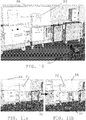
- fig. 7 schematically shows the use of a camera of the video communication device for capturing a video of a part of a process control object at a location of the industrial site
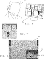
- fig. 8 schematically shows the presentation of the video together with a three-dimensional view of the location and the video communication device
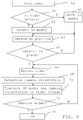
- fig. 9 schematically shows a flow chart of a method of transmitting video to the remote user being performed by the video communication device.
- the control unit 38 first makes the video communication device 32 scan the area at the location, step 56. This may be done through the control unit 38 controlling a motor to rotate the housing 49 around a vertical rotational axis combined with controlling a motor to tilt the housing 49 up and down with different tilt angles as shown in fig. 4a and 4b . In this way a three-dimensional space around the position of the video communication device is captured with different video images using the camera 34.
- the control unit 38 analyses the captured images and investigates if it recognises them with regard to a pre-existing three-dimensional model of the location and objects at this location, i.e. of the process control objects and possible other objects present at the location. If it recognizes the video images and that therefore there is a pre-existing model, step 58, then this model is fetched, step 60.
- the pre-existing three-dimensional model may be provided in the video communication device 32. As an alternative it may be obtained or fetched from a server, such as server 21.
- step 58 a new three-dimensional model 3DM of the location and the various objects in it is created by the control unit 38, step 62. In this case a model is thus obtained through creating it.
- a model may for instance be created using augmented reality functionality.
- the data presenting device comprises an infrared sensor it is also possible to use infrared technology, such as Microsoft Kinect.
- a 3D map of natural features at the location can be built using a variety of feature extraction methods such as corner or edge detection both with 2D RGB data and 3D RGBD (Red, Green, Blue, Depth) data.
- This sparse map it is also possible to determine the location of the video communication device 32 with camera 34.
- the orientation may be calculated based on Registration algorithms. These algorithms can be used to locate the features of a current frame or video image in the map of the real world and based on this the orientation of the camera 34 may be determined.
- the process control objects i.e. the real world objects, may be provided with object identifiers, such as NFC tags or bar codes. If these are read it is possible to obtain information about what types of objects they are. The type may be identified through the camera 34 detecting a visual object identifier, like a bar code. As an alternative the short-range communication unit may be set to read a tag with the object identifier. Such a code may be used to fetch data associated with the object for instance from a database in the process control system. In order to simplify the fetching of such data, the control unit 38 may therefore store an association of the object identifiers to the objects in the model 3DM of the location.
- object identifiers such as NFC tags or bar codes.
- the scanning or short-range communication may also be used by the control unit 38 for determining the position of the video communication device 32 at the location, step 63, i.e. the position in relation to the layout and various objects at the location. This may also involve adding the video communication device to the three-dimensional model 3DM of the location.
- the above mentioned steps may have been performed before a communication session is started with the remote user 52. Such a session may be performed using a TCP connection set up using WiFi and the Internet. As an alternative the steps are performed after a communication session is started.
- the control unit 38 investigates if a communication session is in place or on-going, which in this case at least involves a voice communication session between the remote user and a local user via sound generating equipment and sound recording equipment of the video communication device 32 and the computer 51. It also involves transmission of a live video stream VS, which may be a one way video stream from the video communication device 32 in the process control system to the computer 51 of the remote user 52.
- Video images captured by the camera 34 may thus be transferred to the remote user 52. Also data of the remote user 52 may be made to be projected at the location under the control of the remote user.
- step 64 the control unit 38 waits for one to be started either by the local user or the remote user 52.
- step 64 the control unit 38 controls the camera 34 to record a video stream, step 66. It thus controls the camera 34 to capture video images VI of the location.
- the control unit 38 also continuously determines the camera orientation, step 68, for instance based on the line of sight of a viewfinder of the camera 34. Thereby the control unit 38 determines a current orientation of the video communication device 32.
- the orientation may be provided as a solid angle related to the position of the video communication device and a reference angle.
- the model 3DM may be transmitted from the video communication device to the remote user 52.
- the three-dimensional model 3DM may more particularly be transmitted together with camera data CD in or beside the video stream VS, step 70, where the camera data may comprise the camera orientation.
- the camera data may also comprise the position of the camera, i.e. of the video communication device.
- the control unit 38 modifies the model of the location so that the video communication device and orientation is a part of the model.
- the camera data may thus be provided as a part of the model.
- the orientation may thus be provided as a part of the three-dimensional model that is continuously transferred to the device of the remote user.
- orientation changes may be transmitted as updates of the three-dimensional model during the transfer of video images from the video communication device to the device of the remote user.
- the computer of the remote user may then use these updates in modifying the three-dimensional model.
- the remote user then receives the video stream together with the model 3DM and camera data CD.
- the remote user may then see both the captured video as well as obtain a three-dimensional view of the location using the model 3DM. It is in this way possible for the remote user to see where in the site he is looking.
- Fig. 7 shows how the video communication device 32 is at the same location as the first, second and third process control objects 24, 26 and 28 and how it captures video images of a part of the second process control object 26. It thus records the video for the remote user 52.
- Fig. 8 shows a video image VI in the video stream VS as it would look when displayed on the computer 51 of the remote user 52. This video image may comprise a lot of useful information. However, it may lack context. This context is provided through also transmitting the model 3DM and camera data CD with the video stream VS.
- Fig. 8 shows the screen that the remote user 52 is able to see on the display of his or her computer 51.
- the view contains the live video stream from the camera, of which the image VI is presented. Furthermore, contextual information is provided through an overview image OI of the location, which overview image OI is obtained through visualizing the model 3DM of the location with the video communication device VCD and its orientation. It is here possible that the remote user computer 51 is able to place a representation of the video communication device with the orientation of the image into the model. Alternatively this has already been done by the control unit 38 of the video communication device 32. In the later case a modified model which shows the video communication device and orientation is provided.
- control unit 38 then investigates if the communication session is ended. If it is not, step 72, then video is continued to be recorded and camera orientation determined, step 68 and transferred together with the model to the remote user, step 70. However, if the communication session is ended, step 72, operation is also ended, step 74.
- the remote user may here also be able to navigate in the constructed 3D view and is therefore not limited to observing the current frame from the video transition but is free to "explore" the known 3D model built from the video frames.
- a video conference call where the goal is to share one user's environment, will not be limited to simply streaming video data but may also include data regarding the position as well as current pose or orientation of the camera, where the orientation may be set as the orientation of a line of sight of a view finder of the camera.
- the first variation has a number of further advantages.
- the camera and map data i.e. the camera data and three-dimensional model, are transferred together with a video stream. This increases the situational awareness over a regular video stream, which leads to a less confusing situation and higher location awareness.
- Another advantage is that the number of unnecessary questions are reduced, question such as, "Where are you now?", “What part am I looking at now?” and other deictic questions that engineers collaborating remotely are forced to ask today are avoided.
- fig. 10 schematically shows the location with the video communication device 32 providing a projecting area PA in which a presentation item PI is projected
- fig. 11a and 11b schematically show the location with the video communication device 32 and presentation item PI when the projecting area PA is being moved
- fig. 12 schematically shows a flow chart of a method of operating the video communication device 32 by the remote user 52.
- the video communication device 32 When at the location the video communication device 32 is with advantage used for obtaining data from the location for provision to the remote user 32 and for receiving instructions from the remote user 52 to the local user at the location. This may be done via a two-way voice or video communication.
- control unit 38 When a communication session is on-going the control unit 38 therefore fetches sensor measurements from sensors, such as the temperature sensor and the ambient light sensor and transfers these sensor measurements to the computer 51 of the remote user 52, step 76.
- the camera 34 also captures and transfers video VS to the remote user 52, step 78.
- the remote user 52 may now want to obtain some more data about the process control objects that he sees in the video stream VS. He may for instance desire to obtain data of the temperature in a tank or the voltage of a transformer. In order to do this he may select an object in the video, or in the previously obtained model of the location. He may for instance detect an object identifier in the video and send the object identifier to the video communication device. He may also select an object in the model and the selection may be transferred to the control unit 38. The control unit 38 may then fetch data about the object from a database 20. It may for instance fetch a face plate with current data of the process control object.
- the control unit 38 may therefore receive a process control object selection from the remote user 52, step 80, and based on this selection it fetches process control object data from the process control system such as from the database 20, and transfers the process control object data to the computer 51 of the remote user 52, step 82.
- a remote user 52 may thus select an object in the model of the location and when the object is selected he can obtain additional data such as faceplates with information of the operation.
- the control unit 38 may receive a presentation item PI from the remote user.
- the remote user 52 may more particularly provide presentation items to be projected by the projector.
- the presentation item PI may be a digital presentation item and may be a digital still image such as an image of an arrow or a circle, a presentation such as a slide show or a string of text with an instruction. It may also be a drawing made by the remote user 52.
- the presentation item may thus be a remote user generated presentation item comprising instructions and visual indicators.
- the presentation item PI may therefore be an annotation image that is to be presented to the local user via the projector 48.
- step 84 it is also possible that a selection of position of the presentation item is received.
- the remote user may select a position for the presentation item PI in the 3D model 3DM of the location. This position selection may also be transferred to the control unit 38.
- the control unit 38 then associates the presentation item with the selected position, step 86.
- the position of the presentation item may be set using a solid angle and a radius related to the position of the video communication device and to a reference angle. A presentation item may thereby be assigned to a space in the three-dimensional model of the location. It is also possible to assign more than one presentation item in this way.
- the control unit 38 awaits possible camera control commands from the remote user 52.
- the camera control commands may comprise field of view control commands, such as zooming commands that change the size of the field of view but retains the same line of sight or orientation control commands that change the line of sight.
- Orientation control commands typically comprise panning commands.
- the remote user 52 may thus change the orientation of the camera 34 through rotating or tilting it. He may also zoom in and out. If commands are received, step 88, these commands are then used by the control unit 38. If the commands are field of view commands these are then used for controlling the field of view of the camera, step 90. Zooming commands are forwarded to the camera 34, which then zooms in or out depending on the type of control command. If tilting or rotation is required, the control unit 38 controls a corresponding motor to obtain the required movement.
- the control unit 38 may receive a projector control command from the remote user 52.
- the projector control command may comprise a command to project a presentation item PI. In some instances such a command may also be a command to project the presentation item at a specific desired position.
- the projector 48 is controlled by the control unit 38 according to the command, which involves, if the control command is a command to project a presentation item PI, controlling the projector 48 to project the presentation item PI in the presentation area PA of the projector, step 94. If the command is to project at a specific position the projector is controlled to project the presentation item PI at this position.
- a command may also comprise a command to change the orientation of the presentation area.
- the projector may be moved, using the same or another motor than the one used for the camera 34, and controlled to project the presentation item so that it appears at the desired position, step 94.
- the remote user may thus control the video communication device to project the presentation item at a selected space or position in the location. This may involve projecting the presentation item to a real world position corresponding to the associated position in the three-dimensional model. If a real world object at the location would be in front of the presentation item according to the presentation item position, then parts of the presentation item that would be blocked by the real world object are refrained from being presented.
- the presentation item PI may be set to stay at the user selected position. As the presentation item is associated with the model, this also means that it is possible to retain the presentation item for later session at the location. Furthermore the projection of the presentation item is made independently of the presentation of the video.
- the control unit 38 may therefore control the projector 48 separately from or independently of the control of the camera 34. If for instance the camera 34 stream is zooming in on a detail so that the presentation item PI is outside of the field of view of the camera 34, then the presentation item PI will still be presented. The controlling of the presentation in the presentation area is thus performed independently of the controlling of the field of view of the camera.
- the position of presentation item in the presentation area PA of the projector 48 may be outside of the field of view of the camera.
- the presentation area PA may differ from the field of view of the camera 34.
- the camera control are commands controlling the orientation of the camera and the projector control commands are commands controlling the orientation of the projector it can likewise be seen that the control of the orientation of the projector is performed independently of the control of the orientation of the camera, which thus means that the control of orientation of the camera does not influence the control of the orientation of the projector.
- the projecting area PA of the projector 48 may be movable. If there are several presentation items that may fit in the presentation area when located at a current position, these may be presented singly or simultaneously based on the commands of the remote user.
- the projector 48 may be reoriented so that one or more of these are projected. After assignment, the remote user may simply select a presentation item for being presented and the control unit 38 will control one or motors for reorienting the projector so that the presentation area covers the selected presentation item.
- step 78 Thereafter the capturing of video, is continued, step 78 as well as waiting, step 80, 84, 88 and 92 for various commands from the remote user. This type of operation is continued as long as the session is on-going.
- the remote user 52 may also send commands controlling the projector 48, the camera 34 as well as various sensors, such as the temperature sensor.
- the remote user Through the video communication device 32 it is possible for the remote user to obtain knowledge of the operation of process control objects at the location as well as to obtain other information such as temperature at the location.
- the remote user 52 may also rotate the camera and obtain visual data of the location.
- the remote user may also communicate with a local user and receive audible comments on possible problems at the location.
- the remote user may then determine appropriate actions, such as what process control objects and part of the these that are to be actuated and when.
- the remote user may for instance provide a number of presentation items, such as arrows and explaining text and assign these to different positions in the virtual model.
- the remote user may also provide a timing instruction, providing a sequence in which presentation items are to be presented.
- the commands and presentation items may then be sent to the video communication device 32, which presents them via the projector 48 in an order decided by the remote user 52. If the presentation items are provided in the presentation area at a current position, then these may be presented simultaneously. When a new presentation item needs to be presented that is outside the current field of view of the projector 48, i.e.
- the projector 48 may be moved or reoriented so that the presentation area covers the position of the new presentation item. This movement of the projector 48 may be made independently of the camera 34. In this way it is possible for the remote user 52 to present information at one place, for instance instructions about actuating a certain process control object, while at the same time monitoring another object at another place not covered by the projector 48.
- the second variation thus provides a way to allow a remote user to remotely guide personnel on site via a live video stream.
- the video communication device will also allow the local user and the remote user to communicate verbally. It will also allow the remote user to get an overview of the environment through the camera. The remote user can also scroll, pan and zoom the camera on site to get a superior overview of the situation from the remote location. As a 3D camera is used the remote user will be able to see a 3D model of the environment in case he needs additional space information about the location.
- the remote user can add presentation items or information, such as annotations and drawings to the physical world by using the projector to project information onto the real world, i.e., the remote user can visually share information and annotations with the local user at the location.
- the projector and sound generating equipment may in turn be used to communicate information back from the remote user to the personnel on site.
- the projector is used to for the remote user to visually communicate information back to the plant personnel.
- All visual information provided by the remote user may be augmented reality information, meaning that any annotations or drawings that the remote user adds are saved and connected with the point where they were added by using the constructed 3D model of the environment. This means that if the remote user rotates the camera after an annotation has been added the annotation will stay in the same spot.
- the remote user has added a presentation item PI.
- the remote user rotates the video communication device 32, as can be seen in fig. 11b , for instance in order to get a better overview of the presentation item PI is still projected correctly even through the position of the presentation area PA has been changed. It can thereby be seen that the real world position in which the presentation item is projected is retained even if the presentation area is moved.
- remote users are offered the possibility to instantly give support to any place in the world. No longer are they required to go to a site every time their assistance is needed, instead in many cases they can solve problems from their office.
- Remote users are offered a level of situational awareness that cannot be achieved with video streams alone by building a 3D model of the world.
- Local users such as maintenance-engineers are offered an unobtrusive and natural way of viewing augmented reality information which, in a lot of situations is superior to viewing AR information on a pair of head mounted glasses or via a hand held screen.
- annotations and notes added to the environment and/or the 3D model of the world may also be recorded and saved as part of the maintenance history for the industrial plant. They may also be later retrieved, if the video communication device is brought back to a known location.
- the two variations may be combined.
- the activities in the two variations may thus be carried out in the same communication session.
- the knowledge that the remote user gets of the location in the first variation may be used to control the video communication device and especially in the use of presentation items.
- the video communication device was above described as being provided with a projector and including a tripod. It should be realized that the video communication device may be a handheld device such as a camcorder, laptop computer or a mobile phone, like a smartphone.
- the control unit may, as was mentioned above, be provided in the form of a processor together with memory including computer program code for performing its functions.
- This computer program code may also be provided on one or more data carriers which perform the functionality of the control unit when the program code thereon is being loaded into the memory and run by the processor.
Description
- The present invention generally relates to process control systems. More particularly the present invention relates to a method, computer program product and video communication device for transmitting video to a remote user from an industrial site where a process control system is operated.
- In process control systems it is very important to keep production running at all times as even a minor halt in production will cost large amounts of money. Because of this, maintenance is seen as very important in order to keep the production up and running.
- One useful tool provided for local maintenance in a process control system is described in
SE1300138 - Maintenance can be very expensive as it is sometimes necessary to bring in external experts to help with advanced operations the regular personnel might not have the expertise to handle by themselves.
- Collaboration over a telephone line between the local worker and the expert is not effective enough in all situations as the expert is not able to see what the local worker is doing. Sending pictures back and forth is also a slow way of sharing information. The expert may need to see what happens on site and may need to be able to instruct the personnel on site without the risk of any misinterpretation.
- In such situations it is beneficial to transfer video of the site to the external expert. It is then also possible to zoom in a camera in order to obtain details at the site. However, then it may be hard to retain the context. It may thus be hard to retain an overall view.
- Three-dimensional models have been known to be used in various situations.
-
WO 2012/018497 describes a system where a three-dimensional model of images of a scene of interest is forwarded to a number of handheld computers. Images of a scene are obtained, and provided to a central device that provides the 3D model and exports the model to the handheld devices at the scene. -
US2010/0315416 discloses a system where there is a central computer with a 3D model. In the system cameras are used to capture images of an object, which images are transferred to the central computer and combined with a 3D model. -
DE 102011085003 discusses importing digital images into a virtual environment, which virtual environment is a 3D environment. -
WO 2011/008660 discusses the transmission of positional information of a video camera in a video stream. However, none of the documents discuss the use of three-dimensional models for improving the context of a video stream. - There is thus room for improvement within the field, especially when providing a context for a captured video stream.
- The present invention is concerned with the problem of providing a context for a video stream transmitted from a process control system to a remote user.
- This object is according to a first aspect achieved through a method of transmitting video to a remote user from an industrial site where a process control system is operated, according to claim 1.
- This object is according to a second aspect achieved through a video communication device for transmitting video to a remote user from an industrial site where a process control system is operated, according to claim 7.
- This object is according to a third aspect achieved through a computer program product for transmitting video to a remote user from an industrial site where a process control system is operated, according to claim 13.
- The invention has a number of advantages. The invention provides contextual data in relation to a captured video stream. This increases the situational awareness over a regular video stream, which leads to a less confusing situation and higher location awareness for a remote user that is to interpret information in the video stream. Through the use of the model it is possible to obtain a complete picture of the location where overview can be combined with detail.
- The present invention will in the following be described with reference being made to the accompanying drawings, where
-
Fig. 1 schematically shows an industrial plant with a process control system operating an industrial process together with a video communication device, -
Fig. 2 schematically shows a block schematic of units inside a housing of the video communication device, -
Fig. 3 shows a perspective view of the video communication device in the form of the housing on a tripod, -
Fig. 4a and 4b show perspective views of the video communication device indicating various possibilities of movement of the housing, -
Fig. 5 schematically shows the video communication device communicating with a computer of a remote user via the Internet, -
Fig. 6 schematically shows the remote user with his computer on which video of a location in the process control system is shown, -
Fig. 7 schematically shows the use of a camera of the video communication device for capturing a video of part of a process control object at the location, -
Fig. 8 schematically shows the presentation of the video together with a three-dimensional view of the location and the video communication device, -
Fig. 9 schematically shows a flow chart of a method of transmitting video to the remote user being performed by the video communication device, -
Fig. 10 schematically shows the location with the video communication device providing a projecting area in which a presentation item is provided, -
Fig. 11a and 11b schematically shows the location with the video communication device and presentation item when the projecting area is being moved, -
Fig. 12 schematically shows a flow chart of a method of operating the video communication device by the remote user, and -
Fig. 13 schematically shows a data carrier with computer program code, in the form of a CD-ROM disc, for implementing a control unit of the video communication device. - This invention presents a way for a remote user to gather relevant data and provide instructions and directions for local engineers at a location of an industrial plant where a process control system operates.
-
Fig. 1 schematically shows an industrial plant where aprocess control system 10 is provided. Theprocess control system 10 is a computerized process control system for controlling an industrial process. The process can be any type of industrial process, such as electrical power generation, transmission and distribution processes as well as water purification and distribution processes, oil and gas production and distribution processes, petrochemical, chemical, pharmaceutical and food processes, and pulp and paper production processes. These are just some examples of processes where the system can be applied. There exist countless other industrial processes. The processes may also be other types of industrial processes such as the manufacturing of goods. A process may be monitored through one or more process monitoring computers, which communicate with a server handling monitoring and control of the process. - In
fig. 1 theprocess control system 10 therefore includes a number ofprocess monitoring computers gateway 16 connected to this first data bus B1, whichgateway 16 is connected to at least one wireless network WN. The gateway is also connected to a public data communication network, which is here the internet IN. To the wireless network WN there is connected avideo communication device 32. The wireless network WN may be a local network, such as a wireless local area network (WLAN). It may also be a Bluetooth network, i.e. a network with a number of interconnected Bluetooth nodes. It may also be a mobile communication network. - There is furthermore a second data bus B2 and between the first and second data busses B1 and B2 there are connected a
server 18 providing control and protection of the process and adatabase 20 where data relating to control and protection of the process is stored. Such data relating to control and protection may here comprise process data such as measurements and control commands, while data relating to protection may comprise alarm and event data as well as data on which alarms and events can be generated, such as measurements made in the process. It may also provide face plates of process control objects, which face places may comprise process control data from thedatabase 20 regarding the process control object. There is furthermore an optionalobject data server 21 connected between the two buses B1 and B2. Theobject data server 21 comprises data about all process control objects, such as blueprints, instructions and manuals regarding the process control objects. - To the second data bus B2 there is furthermore connected a number of
further devices further devices process control object 24, a second field device is a secondprocess control object 26 and a third field device is a thirdprocess control object 28. -
Fig. 2 shows a block schematic of a number of units that are provided in thevideo communication device 32. Thevideo communication device 32 is provided with ahousing 49. In thehousing 49 there is provided abus 33, and to thisbus 33 there is connected an optional shortrange communication unit 46 or proximity sensor, avideo projector 48, acamera 34, arecording controller 36, aprogram memory 39, aprocessor 40 as well as aradio communication circuit 42. It may also comprise at least one further sensor, for instance a temperature sensor, accelerometer, ambient light sensor and gyroscope (not shown). Theradio communication circuit 42 is furthermore connected to anantenna 44, where theradio communication unit 42 andantenna 44 are provided for communication with the wireless network WN. Theradio communication circuit 42 andantenna 44 together form one type of communication interface for communicating with the process control system as well as with other entities. It may for this reason be a WiFi or WLAN interface. It may also be a mobile communication interface. It should also be realized that there may be two communication interfaces in the video communication device, one mobile communication interfaces and one WiFi interface. Therecording controller 36 is in turn connected to amicrophone 35. Therecording controller 36 andmicrophone 35 together form a recording unit that may be used for recording sound in a location of the process control system. Although it is not shown, thevideo communication device 32 may also comprise sound emitting units such as speakers and earphones. It is also possible that a microphone and earphone are combined into a headset connected to thevideo communication device 32. The shortrange communication unit 46 may also be regarded as a type of sensor, an object sensor or proximity sensor, for sensing a process control object to be serviced. This sensor may be implemented through Near Field Communication (NFC) technique. - In the
program memory 39 there is provided software code which when being run by theprocessor 40 forms a control unit 38. The control unit 38 is more particularly configured to perform a number of functions under the control of a remote user. - The
video communication device 32 may be moved within the premises of the industrial plant. It may thus be moved from one location to another location. It may also be placed so that it will be able to capture video images and present digital presentations via theprojector 48. For this reason thehousing 49 may be placed on atripod 50, which is schematically shown infig. 3 . Thecamera 34 has a field of view, i.e. an area in which it detects its environment. This field of view may be changed in different ways. It may be increased through zooming out commands and it may be decreased through zoom in commands. The field of view may also be shifted or moved using various types of pan commands. In order to obtain panning, the orientation of the camera may be changed. In a similar manner the projector has a presentation area or projection area, i.e. an area within which it is able to visually present information. The presentation area may be centred on a line of sight of the projector and may have any suitable shape, such as circular, rectangular and quadratic. Also this presentation area may be moved through changing the orientation of the projector. Thecamera 34 may change its orientation in three dimensions. Also theprojector 48 may change its orientation in three dimensions. They may furthermore be independently changeable. In one variation the orientations may be changed jointly through thewhole housing 46 being able to change orientation.Fig. 4a and 4b schematically show movement achieving such reorientation. It can be seen that thehousing 49 may be rotated in a horizontal plane 360 degrees around a vertical axis of rotation of thetripod 50. It can also be seen that thehousing 49 may be tilted vertically upwards or downwards. In order to obtain such movement thevideo communication device 32 may be provided with at least one motor for obtaining such movement. As was mentioned above, it may also be provided with more than one motor, for instance one for providing vertical movement and another for providing horizontal movement. In order to obtain separate movements of the camera and projector, there may also be two such pairs of motors provided, where one pair is provided for thecamera 32 and the other for theprojector 48. These separate movements may furthermore be provided while the camera and projector are still provided inside the same housing. - As was indicated above, the
projector 48 may change orientation independently of the camera. Thecamera 34 andprojector 48 may thus point in different directions. - As can be seen in
fig. 1 thevideo communication device 32 may access the Internet IN via the wireless network WN. This allows thevideo communication device 32 to be operated remotely, i.e. from some other site than the plant. Thevideo communication device 32 may thereby operated by a remote user, for instance via a computer of aremote user 52. This situation is schematically shown infig. 5 . Here it can be seen that acomputer 51 of theremote user 52 may communicate with thevideo communication device 32 via the Internet. The control unit 38 of thevideo communication device 32 may in this way be able to receive commands from theremote user 52, for instance through a web site to which theremote user 52 may log in. As an alternative a control command may be sent directly from thecomputer 51 of theremote user 52. - Thereby the
remote user 52 may be able to obtain video images captured by thecamera 34 of thevideo communication device 32, which video images are then presented for theremote user 52 via the display of his or hercomputer 51. This is shown infig. 6 .Fig. 5 schematically indicates the transmission of a video stream VS, a three-dimensional model 3DM and camera data CD from thevideo communication device 32 to thecomputer 51 of theremote user 52. Information from the sensors may also be sent wirelessly through Internet to the remote user. Information provided by the remote user back to the plant may also be sent through Internet. More information about the transmission will be give shortly. - Now some variations of the invention will be described in more detail.
- In industry, for instance in an industrial plant where a process is being run by a process control system, it is very important to keep production running at all times as even a minor halt in production will cost large amounts of money. Because of this, maintenance is seen as very important in order to keep the production up and running.
- Maintenance can be very expensive as it is sometimes necessary to bring in external experts to help with advanced operations the regular personnel might not have the expertise to handle by themselves. Collaboration over a telephone line between a local worker and the expert is often not good enough. The expert may need to see what happens on site and may need to be able to instruct the personnel on site without the risk of any misinterpretation. Sending pictures back and forth is also a slow way of sharing information, so this is also not really good.
- It can thus take a long time to get hold of the correct expert and fly in this expert to the site. In the case of an unexpected breakdown requiring help from an external expert in order to continue production this can lead to long downtimes as the expert might have to travel long distances to get to the site.
- Flying in an external expert can be very expensive. Not only from the costs associated with the expert (travels, accommodation etc.) but a halt to production as the plant personnel is waiting for the expert to arrive can be very expensive for the owner.
- The above mentioned situation is solved through the use of the video communication device.
- In operation, i.e. when there is some kind of problem at a location in the plant, the video communication device is brought out to this location of the industrial site and placed at a position in the location where assistance is needed. The device may for instance be placed in the centre of a room. The video communication device may be placed at this location by a local user in order to be used for solving a problem at the location, for instance the fact that one or more of the machines or process control objects may be faulty or that the process has a strange behaviour at the location.
- As the device is brought to the location a number of activities may thus be performed.
- In a first variation the remote user is provided with contextual data in relation to a video stream. Now this first variation will be described with reference being made to
fig. 7, 8 and9 , wherefig. 7 schematically shows the use of a camera of the video communication device for capturing a video of a part of a process control object at a location of the industrial site,fig. 8 schematically shows the presentation of the video together with a three-dimensional view of the location and the video communication device andfig. 9 schematically shows a flow chart of a method of transmitting video to the remote user being performed by the video communication device. - According to the first variation, the control unit 38 first makes the
video communication device 32 scan the area at the location,step 56. This may be done through the control unit 38 controlling a motor to rotate thehousing 49 around a vertical rotational axis combined with controlling a motor to tilt thehousing 49 up and down with different tilt angles as shown infig. 4a and 4b . In this way a three-dimensional space around the position of the video communication device is captured with different video images using thecamera 34. - After the area has been scanned, the control unit 38 analyses the captured images and investigates if it recognises them with regard to a pre-existing three-dimensional model of the location and objects at this location, i.e. of the process control objects and possible other objects present at the location. If it recognizes the video images and that therefore there is a pre-existing model,
step 58, then this model is fetched,step 60. The pre-existing three-dimensional model may be provided in thevideo communication device 32. As an alternative it may be obtained or fetched from a server, such asserver 21. If there is a pre-existing model then data about a previous position of the video communication device at the location as well as camera orientations and video streams recorded as the data presenting device was placed at this previous position may be stored together with the model. Also this previous position data and associated historic video streams may be fetched. If any three-dimensional model has been made of the location, then this is thereby obtained. However, if there was no pre-existing model,step 58, a new three-dimensional model 3DM of the location and the various objects in it is created by the control unit 38,step 62. In this case a model is thus obtained through creating it. A model may for instance be created using augmented reality functionality. If the data presenting device comprises an infrared sensor it is also possible to use infrared technology, such as Microsoft Kinect. A 3D map of natural features at the location can be built using a variety of feature extraction methods such as corner or edge detection both with 2D RGB data and 3D RGBD (Red, Green, Blue, Depth) data. Using this sparse map it is also possible to determine the location of thevideo communication device 32 withcamera 34. It is also possible to determine the orientation or pose of thecamera 34. It is thus possible to determine in which direction thecamera 34 is pointing. The orientation may be calculated based on Registration algorithms. These algorithms can be used to locate the features of a current frame or video image in the map of the real world and based on this the orientation of thecamera 34 may be determined. - The process control objects, i.e. the real world objects, may be provided with object identifiers, such as NFC tags or bar codes. If these are read it is possible to obtain information about what types of objects they are. The type may be identified through the
camera 34 detecting a visual object identifier, like a bar code. As an alternative the short-range communication unit may be set to read a tag with the object identifier. Such a code may be used to fetch data associated with the object for instance from a database in the process control system. In order to simplify the fetching of such data, the control unit 38 may therefore store an association of the object identifiers to the objects in the model 3DM of the location. - The scanning or short-range communication may also be used by the control unit 38 for determining the position of the
video communication device 32 at the location, step 63, i.e. the position in relation to the layout and various objects at the location. This may also involve adding the video communication device to the three-dimensional model 3DM of the location. - The above mentioned steps may have been performed before a communication session is started with the
remote user 52. Such a session may be performed using a TCP connection set up using WiFi and the Internet. As an alternative the steps are performed after a communication session is started. In both cases the control unit 38 investigates if a communication session is in place or on-going, which in this case at least involves a voice communication session between the remote user and a local user via sound generating equipment and sound recording equipment of thevideo communication device 32 and thecomputer 51. It also involves transmission of a live video stream VS, which may be a one way video stream from thevideo communication device 32 in the process control system to thecomputer 51 of theremote user 52. - In some instances it may involve a two-way video conference, i.e. where also video is provided by the
computer 51 of theremote user 52 and conveyed to thevideo communication device 32. Video images captured by thecamera 34 may thus be transferred to theremote user 52. Also data of theremote user 52 may be made to be projected at the location under the control of the remote user. - If no session is in place,
step 64, the control unit 38 waits for one to be started either by the local user or theremote user 52. - If however one is on-going,
step 64, the control unit 38 controls thecamera 34 to record a video stream,step 66. It thus controls thecamera 34 to capture video images VI of the location. The control unit 38 also continuously determines the camera orientation,step 68, for instance based on the line of sight of a viewfinder of thecamera 34. Thereby the control unit 38 determines a current orientation of thevideo communication device 32. The orientation may be provided as a solid angle related to the position of the video communication device and a reference angle. As an alternative or in addition, it is also possible to use a gyro and/or accelerometer for determining the orientation. - In the communication session, the model 3DM may be transmitted from the video communication device to the
remote user 52. The three-dimensional model 3DM may more particularly be transmitted together with camera data CD in or beside the video stream VS, step 70, where the camera data may comprise the camera orientation. The camera data may also comprise the position of the camera, i.e. of the video communication device. It is furthermore possible that the control unit 38 modifies the model of the location so that the video communication device and orientation is a part of the model. The camera data may thus be provided as a part of the model. In this case the orientation may thus be provided as a part of the three-dimensional model that is continuously transferred to the device of the remote user. Alternatively orientation changes may be transmitted as updates of the three-dimensional model during the transfer of video images from the video communication device to the device of the remote user. The computer of the remote user may then use these updates in modifying the three-dimensional model. - The remote user then receives the video stream together with the model 3DM and camera data CD. The remote user may then see both the captured video as well as obtain a three-dimensional view of the location using the model 3DM. It is in this way possible for the remote user to see where in the site he is looking.
- An example of this is shown in
fig. 7 and 8. Fig. 7 shows how thevideo communication device 32 is at the same location as the first, second and third process control objects 24, 26 and 28 and how it captures video images of a part of the secondprocess control object 26. It thus records the video for theremote user 52.Fig. 8 shows a video image VI in the video stream VS as it would look when displayed on thecomputer 51 of theremote user 52. This video image may comprise a lot of useful information. However, it may lack context. This context is provided through also transmitting the model 3DM and camera data CD with the video stream VS.Fig. 8 shows the screen that theremote user 52 is able to see on the display of his or hercomputer 51. The view contains the live video stream from the camera, of which the image VI is presented. Furthermore, contextual information is provided through an overview image OI of the location, which overview image OI is obtained through visualizing the model 3DM of the location with the video communication device VCD and its orientation. It is here possible that theremote user computer 51 is able to place a representation of the video communication device with the orientation of the image into the model. Alternatively this has already been done by the control unit 38 of thevideo communication device 32. In the later case a modified model which shows the video communication device and orientation is provided. - The control unit 38 then investigates if the communication session is ended. If it is not, step 72, then video is continued to be recorded and camera orientation determined,
step 68 and transferred together with the model to the remote user,step 70. However, if the communication session is ended,step 72, operation is also ended,step 74. - It can in this way be seen that according to this first variation, it is possible to track the current position and orientation of the
camera 34 in a video conferencing situation while also building a map of the environment so that theremote user 52 can have a better situational awareness of the location. As can be seen infig. 8 , theremote user 52 sees both the current camera view VI, but can also use the small picture OI in the right corner to get an excellent overview of the surroundings. - The remote user may here also be able to navigate in the constructed 3D view and is therefore not limited to observing the current frame from the video transition but is free to "explore" the known 3D model built from the video frames.
- A video conference call, where the goal is to share one user's environment, will not be limited to simply streaming video data but may also include data regarding the position as well as current pose or orientation of the camera, where the orientation may be set as the orientation of a line of sight of a view finder of the camera.
- If a previous model existed, it is furthermore possible for the remote user to fetch video streams previously recorded at the location with positions of the video communication device and camera orientations when these historic video streams were recorded.
- Some advantages of the invention can be better realized from the following scenario:
- 1. A local maintenance engineer is doing some maintenance on the factory floor when he identifies a potential issue; he calls the remote user and starts a video call to get advice on the situation.
- 2. He uses the camera on the video communication device and makes it scan the location to show the current situation of a process control object, in this example the second
process control object 26, as well as the surrounding environment. - 3. Different frames of the video are processed to form a map of the environment. In the forming of the map also the position of the video communication device is determined. Using this map and a current video image, the current orientation or pose of the camera is calculated.
- 4. The map 3DM of the environment with camera data are then sent over the network during the call along with the video stream.
- 5. This additional information helps the remote user to orientate himself in the world given the dynamic nature of the orientation of the camera, as he can see the map of the environment and the video stream simultaneously. The remote user gets a much better situational awareness than a normal video conference system would give him.
- 6. The two users may then manage to solve the situation thanks to the efficiency of the video collaboration system that enables the remote user to get a very clear understanding of the local environment in the industrial site.
- The first variation has a number of further advantages. In the first variation the camera and map data, i.e. the camera data and three-dimensional model, are transferred together with a video stream. This increases the situational awareness over a regular video stream, which leads to a less confusing situation and higher location awareness.
- The streamed data is used to create a complete picture of the location. The remote user can use this 3D model to navigate the point of view independently of the physical camera position; this will give the remote user a great situational awareness.
- Another advantage is that the number of unnecessary questions are reduced, question such as, "Where are you now?", "What part am I looking at now?" and other deictic questions that engineers collaborating remotely are forced to ask today are avoided.
- The communication will also become more accurate. Communication errors relating to location will be less common.
- The collaboration between the two users will also become more efficient. The time taken for video collaboration task to be completed will most probably be improved.
- It is furthermore possible that the safety is increased. As the remote user has a better awareness of the situation at hand, he can observe whether the local user is performing the correct actions.
- A second variation will now be described with reference being made to
fig. 10, 11a, 11b and12 , wherefig. 10 schematically shows the location with thevideo communication device 32 providing a projecting area PA in which a presentation item PI is projected,fig. 11a and 11b schematically show the location with thevideo communication device 32 and presentation item PI when the projecting area PA is being moved, andfig. 12 schematically shows a flow chart of a method of operating thevideo communication device 32 by theremote user 52. - When at the location the
video communication device 32 is with advantage used for obtaining data from the location for provision to theremote user 32 and for receiving instructions from theremote user 52 to the local user at the location. This may be done via a two-way voice or video communication. - When a communication session is on-going the control unit 38 therefore fetches sensor measurements from sensors, such as the temperature sensor and the ambient light sensor and transfers these sensor measurements to the
computer 51 of theremote user 52,step 76. Thecamera 34 also captures and transfers video VS to theremote user 52,step 78. - The
remote user 52 may now want to obtain some more data about the process control objects that he sees in the video stream VS. He may for instance desire to obtain data of the temperature in a tank or the voltage of a transformer. In order to do this he may select an object in the video, or in the previously obtained model of the location. He may for instance detect an object identifier in the video and send the object identifier to the video communication device. He may also select an object in the model and the selection may be transferred to the control unit 38. The control unit 38 may then fetch data about the object from adatabase 20. It may for instance fetch a face plate with current data of the process control object. - The control unit 38 may therefore receive a process control object selection from the
remote user 52,step 80, and based on this selection it fetches process control object data from the process control system such as from thedatabase 20, and transfers the process control object data to thecomputer 51 of theremote user 52,step 82. Aremote user 52 may thus select an object in the model of the location and when the object is selected he can obtain additional data such as faceplates with information of the operation. - After a process control object is selected or if no process control object is selected, the control unit 38 may receive a presentation item PI from the remote user. The
remote user 52 may more particularly provide presentation items to be projected by the projector. The presentation item PI may be a digital presentation item and may be a digital still image such as an image of an arrow or a circle, a presentation such as a slide show or a string of text with an instruction. It may also be a drawing made by theremote user 52. The presentation item may thus be a remote user generated presentation item comprising instructions and visual indicators. The presentation item PI may therefore be an annotation image that is to be presented to the local user via theprojector 48. If such a presentation item PI is received,step 84, it is also possible that a selection of position of the presentation item is received. The remote user may select a position for the presentation item PI in the 3D model 3DM of the location. This position selection may also be transferred to the control unit 38. The control unit 38 then associates the presentation item with the selected position,step 86. The position of the presentation item may be set using a solid angle and a radius related to the position of the video communication device and to a reference angle. A presentation item may thereby be assigned to a space in the three-dimensional model of the location. It is also possible to assign more than one presentation item in this way. - Thereafter the control unit 38 awaits possible camera control commands from the
remote user 52. The camera control commands may comprise field of view control commands, such as zooming commands that change the size of the field of view but retains the same line of sight or orientation control commands that change the line of sight. Orientation control commands typically comprise panning commands. Theremote user 52 may thus change the orientation of thecamera 34 through rotating or tilting it. He may also zoom in and out. If commands are received,step 88, these commands are then used by the control unit 38. If the commands are field of view commands these are then used for controlling the field of view of the camera,step 90. Zooming commands are forwarded to thecamera 34, which then zooms in or out depending on the type of control command. If tilting or rotation is required, the control unit 38 controls a corresponding motor to obtain the required movement. - Thereafter the control unit 38 may receive a projector control command from the
remote user 52. The projector control command may comprise a command to project a presentation item PI. In some instances such a command may also be a command to project the presentation item at a specific desired position. If a projector control command is received,step 92, theprojector 48 is controlled by the control unit 38 according to the command, which involves, if the control command is a command to project a presentation item PI, controlling theprojector 48 to project the presentation item PI in the presentation area PA of the projector,step 94. If the command is to project at a specific position the projector is controlled to project the presentation item PI at this position. A command may also comprise a command to change the orientation of the presentation area. In this case the projector may be moved, using the same or another motor than the one used for thecamera 34, and controlled to project the presentation item so that it appears at the desired position,step 94. The remote user may thus control the video communication device to project the presentation item at a selected space or position in the location. This may involve projecting the presentation item to a real world position corresponding to the associated position in the three-dimensional model. If a real world object at the location would be in front of the presentation item according to the presentation item position, then parts of the presentation item that would be blocked by the real world object are refrained from being presented. - If the projector is reoriented so that the presentation area PA is moved, the presentation item PI may be set to stay at the user selected position. As the presentation item is associated with the model, this also means that it is possible to retain the presentation item for later session at the location. Furthermore the projection of the presentation item is made independently of the presentation of the video. The control unit 38 may therefore control the
projector 48 separately from or independently of the control of thecamera 34. If for instance thecamera 34 stream is zooming in on a detail so that the presentation item PI is outside of the field of view of thecamera 34, then the presentation item PI will still be presented. The controlling of the presentation in the presentation area is thus performed independently of the controlling of the field of view of the camera. As is evident from the zooming example given above, this thus means that the position of presentation item in the presentation area PA of theprojector 48 may be outside of the field of view of the camera. This also means that the presentation area PA may differ from the field of view of thecamera 34. When the camera control are commands controlling the orientation of the camera and the projector control commands are commands controlling the orientation of the projector it can likewise be seen that the control of the orientation of the projector is performed independently of the control of the orientation of the camera, which thus means that the control of orientation of the camera does not influence the control of the orientation of the projector. - As can be seen in
fig. 11a and 11b , the projecting area PA of theprojector 48 may be movable. If there are several presentation items that may fit in the presentation area when located at a current position, these may be presented singly or simultaneously based on the commands of the remote user. - If for instance several presentation items are provided, where some are outside of the current location of the presentation area PA, the
projector 48 may be reoriented so that one or more of these are projected. After assignment, the remote user may simply select a presentation item for being presented and the control unit 38 will control one or motors for reorienting the projector so that the presentation area covers the selected presentation item. - Thereafter the capturing of video, is continued, step 78 as well as waiting,
step - The
remote user 52 may also send commands controlling theprojector 48, thecamera 34 as well as various sensors, such as the temperature sensor. - Through the
video communication device 32 it is possible for the remote user to obtain knowledge of the operation of process control objects at the location as well as to obtain other information such as temperature at the location. In order to observe the location theremote user 52 may also rotate the camera and obtain visual data of the location. Through the voice connection the remote user may also communicate with a local user and receive audible comments on possible problems at the location. - The remote user may then determine appropriate actions, such as what process control objects and part of the these that are to be actuated and when. The remote user may for instance provide a number of presentation items, such as arrows and explaining text and assign these to different positions in the virtual model. The remote user may also provide a timing instruction, providing a sequence in which presentation items are to be presented. The commands and presentation items may then be sent to the
video communication device 32, which presents them via theprojector 48 in an order decided by theremote user 52. If the presentation items are provided in the presentation area at a current position, then these may be presented simultaneously. When a new presentation item needs to be presented that is outside the current field of view of theprojector 48, i.e. outside the presentation area when in its current position, theprojector 48 may be moved or reoriented so that the presentation area covers the position of the new presentation item. This movement of theprojector 48 may be made independently of thecamera 34. In this way it is possible for theremote user 52 to present information at one place, for instance instructions about actuating a certain process control object, while at the same time monitoring another object at another place not covered by theprojector 48. - The second variation thus provides a way to allow a remote user to remotely guide personnel on site via a live video stream. The video communication device will also allow the local user and the remote user to communicate verbally. It will also allow the remote user to get an overview of the environment through the camera. The remote user can also scroll, pan and zoom the camera on site to get a superior overview of the situation from the remote location. As a 3D camera is used the remote user will be able to see a 3D model of the environment in case he needs additional space information about the location.
- It is also possible for the remote user to add presentation items or information, such as annotations and drawings to the physical world by using the projector to project information onto the real world, i.e., the remote user can visually share information and annotations with the local user at the location.
- All the sensors together with camera and sound recording equipment will enable a remote connected user to see, hear and feel the situation at the plant. The projector and sound generating equipment, may in turn be used to communicate information back from the remote user to the personnel on site. The projector is used to for the remote user to visually communicate information back to the plant personnel.
- By allowing the remote user to take control of the video communication device, the remote user can browse the surroundings using the camera, by rotating, tilting and zooming. Once the remote user has information that he/she wants to share with the local users on site he can "draw" this information on to the presentation area using the projector. The remote user can use text, images, or simply draw objects on the remote screen. The drawings will then be projected on site using the projector. As the camera records a 3D model of the environment, the notes can also be left behind objects.
- All visual information provided by the remote user may be augmented reality information, meaning that any annotations or drawings that the remote user adds are saved and connected with the point where they were added by using the constructed 3D model of the environment. This means that if the remote user rotates the camera after an annotation has been added the annotation will stay in the same spot.
- As can be seen in
fig. 11 the remote user has added a presentation item PI. As the remote user rotates thevideo communication device 32, as can be seen infig. 11b , for instance in order to get a better overview of the presentation item PI is still projected correctly even through the position of the presentation area PA has been changed. It can thereby be seen that the real world position in which the presentation item is projected is retained even if the presentation area is moved. - Imagine the following scenario:
- 1. A Norwegian gas company unexpectedly experiences severe trouble at one of their offshore platforms. The problem is rare and technically complex, the operators on site need support from an expert in order to restore production.
- 2. Flying in an expert will take at least 48 hours as all experts are located far away.
- 3. The operator contacts a support company where an expert in this technical subject is available to instantly help the offshore platform with the problem.
- 4. Operators have discussions with the expert, the expert instructs the operators on site to bring the video communication device to a specific part of the process so that the remote expert can have a look at the problem.
- 5. The remote expert observes the situation using the camera, sound recording equipment and sensors.
- 6. Based on the information from the offshore platform the remote expert can now instruct the operators on site to perform certain operations to correct the problem.
- 7. The remote expert utilizes both voice and the possibility to visually share information with the users offshore. The possibility for the remote expert to use both voice and to visually share information is extremely effective as it is possible for the remote expert to instantly "point out" where operators on site should perform actions.
- Through the second variation remote users are offered the possibility to instantly give support to any place in the world. No longer are they required to go to a site every time their assistance is needed, instead in many cases they can solve problems from their office. Remote users are offered a level of situational awareness that cannot be achieved with video streams alone by building a 3D model of the world.
- Local users, such as maintenance-engineers are offered an unobtrusive and natural way of viewing augmented reality information which, in a lot of situations is superior to viewing AR information on a pair of head mounted glasses or via a hand held screen.
- The remote user is able to add notes to the environment that are projected onto the actual surface of the equipment for the local maintenance engineer to view.
- There is a possibility to add notes to a 3D model of the world and display those notes on spot by using projectors
- Notes added to the 3D model stick to their place even if the camera covers another position.
- The annotations and notes added to the environment and/or the 3D model of the world may also be recorded and saved as part of the maintenance history for the industrial plant. They may also be later retrieved, if the video communication device is brought back to a known location.
- It should also be realized that the two variations may be combined. The activities in the two variations may thus be carried out in the same communication session. In this case the knowledge that the remote user gets of the location in the first variation may be used to control the video communication device and especially in the use of presentation items.
- The video communication device was above described as being provided with a projector and including a tripod. It should be realized that the video communication device may be a handheld device such as a camcorder, laptop computer or a mobile phone, like a smartphone.
- The control unit may, as was mentioned above, be provided in the form of a processor together with memory including computer program code for performing its functions. This computer program code may also be provided on one or more data carriers which perform the functionality of the control unit when the program code thereon is being loaded into the memory and run by the processor. One
such data carrier 96 withcomputer program code 98, in the form of a CD ROM disc, is schematically shown infig. 13 . - The invention can be varied in many more ways than the ones already mentioned. It should therefore be realized that the present invention is only to be limited by the following claims.
Claims (13)
- A method of transmitting video to a remote user from an industrial site where a process control system (10) is operated, the method being performed by a video communication device (32) being placed at a location of the industrial site and performed in relation to a communication session carried out between the video communication device and a device (51) of the remote user, the method comprising:- obtaining (60; 62) a three-dimensional model (3DM) of the location and the various objects at the location,- obtaining (63) the position of the video communication device at the location,- capturing (66) video images (VI) of the location using a camera (34)of the video communication device,- determining (68) a current orientation of the camera,- adding a representation of the video communication device to the three-dimensional model of the location so that the video communication device is shown in the model, and- transferring, in the communication session from the video communication device to the device of the remote user, the three-dimensional model and the orientation of the camera and the position of the video communication device together with a video stream comprising the captured video images.
- The method according to claim 1, further comprising investigating if there is a pre-existing three-dimensional model of the location, fetching (60) and using the pre-existing model if (58) there is one and otherwise creating (62) the three-dimensional model based on scanning (56) the location.
- The method according to any previous claim, wherein the orientation of the camera is provided as a solid angle related to the position of the video communication device and a reference angle.
- The method according to claim 2, if there is a pre-existing three-dimensional model further comprising obtaining previous positions of the video communication device, possibly together with previous orientations of the camera and video recordings made at these previous positions.
- The method according to any previous claim wherein the orientation of the camera is provided as a part of the three-dimensional model that is continuously transferred to the device of the remote user.
- The method according to any of claims 1 - 4, wherein the orientation of the camera is transferred as updates of the three-dimensional model during the transfer of video images from the video communication device to the device of the remote user.
- A video communication device (32) for transmitting video to a remote user (52) from an industrial site where a process control system (10) is operated, the video communication device (32) being placed at a location of the industrial site and comprising:- a communication interface (42, 44) for providing a communication session between the video communication device and a device (51) of the remote user (52),- a camera (34) capturing images, and- a control unit (38) configured toobtain a three-dimensional model (3DM) of the location and the various objects at the location,obtain the position of the video communication device at the location,control the camera to capture video images (VI) of the location,determine a current orientation of the camera, add a representation of the video communication device to the three-dimensional model of the location so that the video communication device is shown in the model, andtransfer, in the communication session from the video communication device to the device of the remote user, the three-dimensional model and the orientation of the camera and the position of the video communication device together with a video stream from the camera comprising the captured video images.
- The video communication device according to claim 7, the control unit being further configured to investigate if there is a pre-existing three-dimensional model of the location, fetch and use the pre-existing model if there is one and otherwise create the three-dimensional model based on scanning the location using the camera.
- The video communication device according to claim 7 or 8, wherein the orientation of the camera is provided as a solid angle related to the position of the video communication device and a reference angle.
- The video communication device according to claim 8, wherein if there is a pre-existing three-dimensional model, the control unit is further configured to obtain previous positions of the video communication device, possibly together with previous orientations of the camera and video recordings made at these previous positions.
- The video communication device according to any of claims 7 - 10, wherein the orientation of the camera is provided as a part of the three-dimensional model that is continuously transferred to the device of the remote user.
- The video communication device according to any of claims 7 - 10, wherein the orientation of the camera is transferred as updates of the three-dimensional model during the transfer of video images from the video communication device to the device of the remote user.
- A computer program product for transmitting video to a remote user (52) from an industrial site where a process control system (10) is operated, said computer program product being provided on a data carrier (96) comprising computer program code (98) configured to cause a video communication device (32) comprising a camera (34) to, when said computer program code is loaded into the video communication device and the video communication device is placed at a location of the industrial site and there is a communication session between the video communication device and a device (51) of the remote user,- obtain a three-dimensional model (3DM) of the location and the various objects at the location,- obtain the position of the video communication device at the location,- capture video images (VI) of the location using the camera (34),- determine a current orientation of the camera,- add a representation of the video communication device to the three-dimensional model of the location so that the video communication device is shown in the model, and- transfer, in the communication session from the video communication device to the device of the remote user, the three-dimensional model and the orientation of the camera and the position of the video communication device together with a video stream comprising the captured video images.
Applications Claiming Priority (1)
| Application Number | Priority Date | Filing Date | Title |
|---|---|---|---|
| PCT/EP2013/063539 WO2014206473A1 (en) | 2013-06-27 | 2013-06-27 | Method and video communication device for transmitting video to a remote user |
Publications (2)
| Publication Number | Publication Date |
|---|---|
| EP3014367A1 EP3014367A1 (en) | 2016-05-04 |
| EP3014367B1 true EP3014367B1 (en) | 2017-03-15 |
Family
ID=48703510
Family Applications (1)
| Application Number | Title | Priority Date | Filing Date |
|---|---|---|---|
| EP13732486.9A Active EP3014367B1 (en) | 2013-06-27 | 2013-06-27 | Method and video communication device for transmitting video to a remote user |
Country Status (4)
| Country | Link |
|---|---|
| US (1) | US9628772B2 (en) |
| EP (1) | EP3014367B1 (en) |
| CN (1) | CN105659170B (en) |
| WO (1) | WO2014206473A1 (en) |
Families Citing this family (71)
| Publication number | Priority date | Publication date | Assignee | Title |
|---|---|---|---|---|
| US9411327B2 (en) | 2012-08-27 | 2016-08-09 | Johnson Controls Technology Company | Systems and methods for classifying data in building automation systems |
| EP2818948B1 (en) * | 2013-06-27 | 2016-11-16 | ABB Schweiz AG | Method and data presenting device for assisting a remote user to provide instructions |
| US20160035246A1 (en) * | 2014-07-31 | 2016-02-04 | Peter M. Curtis | Facility operations management using augmented reality |
| US20160054900A1 (en) * | 2014-08-25 | 2016-02-25 | Chuck Surack | Computer Implemented System and Method for Producing 360 Degree Perspective Images |
| US9760635B2 (en) | 2014-11-07 | 2017-09-12 | Rockwell Automation Technologies, Inc. | Dynamic search engine for an industrial environment |
| US9947135B2 (en) * | 2015-04-14 | 2018-04-17 | ETAK Systems, LLC | Close-out audit systems and methods for cell site installation and maintenance |
| US10893419B2 (en) * | 2015-04-14 | 2021-01-12 | ETAK Systems, LLC | Systems and methods for coordinating initiation, preparing, vetting, scheduling, constructing, and implementing a small cell implementation |
| US10959107B2 (en) * | 2015-04-14 | 2021-03-23 | ETAK Systems, LLC | Systems and methods for delivering a close out package for work done at a telecommunications site |
| US11790124B2 (en) * | 2015-04-14 | 2023-10-17 | ETAK Systems, LLC | Systems and methods for coordinating initiation, preparing, vetting, scheduling, constructing, and implementing a power plant implementation |
| US10255719B2 (en) * | 2015-04-14 | 2019-04-09 | ETAK Systems, LLC | Systems and methods for satellite data capture for telecommunications site modeling |
| US11797723B2 (en) * | 2015-04-14 | 2023-10-24 | ETAK Systems, LLC | Systems and methods for coordinating initiation, preparing, vetting, scheduling, constructing, and implementing a power plant implementation |
| US10169917B2 (en) | 2015-08-20 | 2019-01-01 | Microsoft Technology Licensing, Llc | Augmented reality |
| US10235808B2 (en) | 2015-08-20 | 2019-03-19 | Microsoft Technology Licensing, Llc | Communication system |
| US20170053455A1 (en) * | 2015-08-20 | 2017-02-23 | Microsoft Technology Licensing, Llc | Asynchronous 3D annotation of a Video Sequence |
| US10534326B2 (en) | 2015-10-21 | 2020-01-14 | Johnson Controls Technology Company | Building automation system with integrated building information model |
| US11947785B2 (en) | 2016-01-22 | 2024-04-02 | Johnson Controls Technology Company | Building system with a building graph |
| US11268732B2 (en) | 2016-01-22 | 2022-03-08 | Johnson Controls Technology Company | Building energy management system with energy analytics |
| US11768004B2 (en) | 2016-03-31 | 2023-09-26 | Johnson Controls Tyco IP Holdings LLP | HVAC device registration in a distributed building management system |
| US10325155B2 (en) * | 2016-04-19 | 2019-06-18 | Rockwell Automation Technologies, Inc. | Analyzing video streams in an industrial environment to identify potential problems and select recipients for a display of video streams related to the potential problems |
| US10613729B2 (en) * | 2016-05-03 | 2020-04-07 | Johnson Controls Technology Company | Building and security management system with augmented reality interface |
| US10505756B2 (en) | 2017-02-10 | 2019-12-10 | Johnson Controls Technology Company | Building management system with space graphs |
| US11774920B2 (en) | 2016-05-04 | 2023-10-03 | Johnson Controls Technology Company | Building system with user presentation composition based on building context |
| US10901373B2 (en) | 2017-06-15 | 2021-01-26 | Johnson Controls Technology Company | Building management system with artificial intelligence for unified agent based control of building subsystems |
| US10417451B2 (en) | 2017-09-27 | 2019-09-17 | Johnson Controls Technology Company | Building system with smart entity personal identifying information (PII) masking |
| US10684033B2 (en) | 2017-01-06 | 2020-06-16 | Johnson Controls Technology Company | HVAC system with automated device pairing |
| US10957102B2 (en) * | 2017-01-16 | 2021-03-23 | Ncr Corporation | Virtual reality maintenance and repair |
| US11900287B2 (en) | 2017-05-25 | 2024-02-13 | Johnson Controls Tyco IP Holdings LLP | Model predictive maintenance system with budgetary constraints |
| US11360447B2 (en) | 2017-02-10 | 2022-06-14 | Johnson Controls Technology Company | Building smart entity system with agent based communication and control |
| US10095756B2 (en) | 2017-02-10 | 2018-10-09 | Johnson Controls Technology Company | Building management system with declarative views of timeseries data |
| US11280509B2 (en) | 2017-07-17 | 2022-03-22 | Johnson Controls Technology Company | Systems and methods for agent based building simulation for optimal control |
| US10515098B2 (en) | 2017-02-10 | 2019-12-24 | Johnson Controls Technology Company | Building management smart entity creation and maintenance using time series data |
| US11764991B2 (en) | 2017-02-10 | 2023-09-19 | Johnson Controls Technology Company | Building management system with identity management |
| US20190361412A1 (en) | 2017-02-10 | 2019-11-28 | Johnson Controls Technology Company | Building smart entity system with agent based data ingestion and entity creation using time series data |
| WO2018175912A1 (en) | 2017-03-24 | 2018-09-27 | Johnson Controls Technology Company | Building management system with dynamic channel communication |
| US11327737B2 (en) | 2017-04-21 | 2022-05-10 | Johnson Controls Tyco IP Holdings LLP | Building management system with cloud management of gateway configurations |
| US10788229B2 (en) | 2017-05-10 | 2020-09-29 | Johnson Controls Technology Company | Building management system with a distributed blockchain database |
| US11022947B2 (en) | 2017-06-07 | 2021-06-01 | Johnson Controls Technology Company | Building energy optimization system with economic load demand response (ELDR) optimization and ELDR user interfaces |
| EP3655825B1 (en) | 2017-07-21 | 2023-11-22 | Johnson Controls Tyco IP Holdings LLP | Building management system with dynamic rules with sub-rule reuse and equation driven smart diagnostics |
| US20190033811A1 (en) | 2017-07-27 | 2019-01-31 | Johnson Controls Technology Company | Building management system with on-demand meter roll-ups |
| US10962945B2 (en) | 2017-09-27 | 2021-03-30 | Johnson Controls Technology Company | Building management system with integration of data into smart entities |
| US10565844B2 (en) | 2017-09-27 | 2020-02-18 | Johnson Controls Technology Company | Building risk analysis system with global risk dashboard |
| US11314726B2 (en) | 2017-09-27 | 2022-04-26 | Johnson Controls Tyco IP Holdings LLP | Web services for smart entity management for sensor systems |
| US11281169B2 (en) | 2017-11-15 | 2022-03-22 | Johnson Controls Tyco IP Holdings LLP | Building management system with point virtualization for online meters |
| US10809682B2 (en) | 2017-11-15 | 2020-10-20 | Johnson Controls Technology Company | Building management system with optimized processing of building system data |
| US11127235B2 (en) | 2017-11-22 | 2021-09-21 | Johnson Controls Tyco IP Holdings LLP | Building campus with integrated smart environment |
| CN108156443A (en) * | 2017-12-21 | 2018-06-12 | 成都真实维度科技有限公司 | A kind of operation VR live streaming platforms and its business model |
| US10832558B2 (en) * | 2018-01-08 | 2020-11-10 | Honeywell International Inc. | Systems and methods for augmenting reality during a site survey using an unmanned aerial vehicle |
| US11954713B2 (en) | 2018-03-13 | 2024-04-09 | Johnson Controls Tyco IP Holdings LLP | Variable refrigerant flow system with electricity consumption apportionment |
| US11016648B2 (en) | 2018-10-30 | 2021-05-25 | Johnson Controls Technology Company | Systems and methods for entity visualization and management with an entity node editor |
| US11927925B2 (en) | 2018-11-19 | 2024-03-12 | Johnson Controls Tyco IP Holdings LLP | Building system with a time correlated reliability data stream |
| US11221661B2 (en) | 2019-01-14 | 2022-01-11 | Rockwell Automation Technologies, Inc. | Method for auto-discovery and categorization of a plants power and energy smart devices for analytics |
| US11436567B2 (en) | 2019-01-18 | 2022-09-06 | Johnson Controls Tyco IP Holdings LLP | Conference room management system |
| US10788798B2 (en) | 2019-01-28 | 2020-09-29 | Johnson Controls Technology Company | Building management system with hybrid edge-cloud processing |
| US11894944B2 (en) | 2019-12-31 | 2024-02-06 | Johnson Controls Tyco IP Holdings LLP | Building data platform with an enrichment loop |
| US20210200164A1 (en) | 2019-12-31 | 2021-07-01 | Johnson Controls Technology Company | Building data platform with edge based event enrichment |
| US11537386B2 (en) | 2020-04-06 | 2022-12-27 | Johnson Controls Tyco IP Holdings LLP | Building system with dynamic configuration of network resources for 5G networks |
| CN111885398B (en) * | 2020-07-20 | 2021-12-07 | 贝壳找房(北京)科技有限公司 | Interaction method, device and system based on three-dimensional model, electronic equipment and storage medium |
| CN111787341B (en) * | 2020-05-29 | 2023-12-05 | 北京京东尚科信息技术有限公司 | Guide broadcasting method, device and system |
| US11874809B2 (en) | 2020-06-08 | 2024-01-16 | Johnson Controls Tyco IP Holdings LLP | Building system with naming schema encoding entity type and entity relationships |
| US11397773B2 (en) | 2020-09-30 | 2022-07-26 | Johnson Controls Tyco IP Holdings LLP | Building management system with semantic model integration |
| US11954154B2 (en) | 2020-09-30 | 2024-04-09 | Johnson Controls Tyco IP Holdings LLP | Building management system with semantic model integration |
| US20220137575A1 (en) | 2020-10-30 | 2022-05-05 | Johnson Controls Technology Company | Building management system with dynamic building model enhanced by digital twins |
| CN117280291A (en) | 2021-03-17 | 2023-12-22 | 江森自控泰科知识产权控股有限责任合伙公司 | System and method for determining device energy waste |
| US11769066B2 (en) | 2021-11-17 | 2023-09-26 | Johnson Controls Tyco IP Holdings LLP | Building data platform with digital twin triggers and actions |
| US11899723B2 (en) | 2021-06-22 | 2024-02-13 | Johnson Controls Tyco IP Holdings LLP | Building data platform with context based twin function processing |
| US11796974B2 (en) | 2021-11-16 | 2023-10-24 | Johnson Controls Tyco IP Holdings LLP | Building data platform with schema extensibility for properties and tags of a digital twin |
| US11934966B2 (en) | 2021-11-17 | 2024-03-19 | Johnson Controls Tyco IP Holdings LLP | Building data platform with digital twin inferences |
| US11704311B2 (en) | 2021-11-24 | 2023-07-18 | Johnson Controls Tyco IP Holdings LLP | Building data platform with a distributed digital twin |
| US11714930B2 (en) | 2021-11-29 | 2023-08-01 | Johnson Controls Tyco IP Holdings LLP | Building data platform with digital twin based inferences and predictions for a graphical building model |
| WO2023180456A1 (en) * | 2022-03-23 | 2023-09-28 | Basf Se | Method and apparatus for monitoring an industrial plant |
| CN115643365B (en) * | 2022-12-26 | 2023-03-28 | 北京天智航医疗技术服务有限公司 | Remote operation control method and device and electronic equipment |
Family Cites Families (8)
| Publication number | Priority date | Publication date | Assignee | Title |
|---|---|---|---|---|
| AU2001250802A1 (en) * | 2000-03-07 | 2001-09-17 | Sarnoff Corporation | Camera pose estimation |
| RU2498408C2 (en) | 2007-12-10 | 2013-11-10 | Абб Рисерч Лтд | Computer-implemented method and system for remote control of production process |
| US20110007150A1 (en) | 2009-07-13 | 2011-01-13 | Raytheon Company | Extraction of Real World Positional Information from Video |
| IL202460A (en) * | 2009-12-01 | 2013-08-29 | Rafael Advanced Defense Sys | Method and system of generating a three-dimensional view of a real scene |
| US20120019522A1 (en) * | 2010-07-25 | 2012-01-26 | Raytheon Company | ENHANCED SITUATIONAL AWARENESS AND TARGETING (eSAT) SYSTEM |
| US8587583B2 (en) * | 2011-01-31 | 2013-11-19 | Microsoft Corporation | Three-dimensional environment reconstruction |
| DE102011085003A1 (en) | 2011-10-21 | 2013-04-25 | Siemens Aktiengesellschaft | Method for visualizing spatial relationships of manufacturing plant, involves providing navigation tool to select viewer views of digital images in virtual environment |
| SE1300138A1 (en) | 2013-02-21 | 2013-02-25 | Abb Technology Ltd | Method and data presentation device for assisting a user to service a process control object |
-
2013
- 2013-06-27 WO PCT/EP2013/063539 patent/WO2014206473A1/en active Application Filing
- 2013-06-27 CN CN201380077726.9A patent/CN105659170B/en active Active
- 2013-06-27 EP EP13732486.9A patent/EP3014367B1/en active Active
- 2013-06-27 US US14/895,121 patent/US9628772B2/en active Active
Non-Patent Citations (1)
| Title |
|---|
| None * |
Also Published As
| Publication number | Publication date |
|---|---|
| US20160127712A1 (en) | 2016-05-05 |
| WO2014206473A1 (en) | 2014-12-31 |
| EP3014367A1 (en) | 2016-05-04 |
| CN105659170B (en) | 2019-02-12 |
| US9628772B2 (en) | 2017-04-18 |
| CN105659170A (en) | 2016-06-08 |
Similar Documents
| Publication | Publication Date | Title |
|---|---|---|
| EP3014367B1 (en) | Method and video communication device for transmitting video to a remote user | |
| US9829873B2 (en) | Method and data presenting device for assisting a remote user to provide instructions | |
| CN111149133B (en) | Virtual X-ray vision in a process control environment | |
| WO2020211428A1 (en) | Park area safety supervisory system and method | |
| KR102289745B1 (en) | System and method for real-time monitoring field work | |
| JP2016220173A (en) | Tracking support device, tracking support system and tracking support method | |
| US20220301270A1 (en) | Systems and methods for immersive and collaborative video surveillance | |
| EP3857851A1 (en) | Methods, systems, and media for indicating a security status of an internet of things device | |
| US11816887B2 (en) | Quick activation techniques for industrial augmented reality applications | |
| US11736802B2 (en) | Communication management apparatus, image communication system, communication management method, and recording medium | |
| US20160323498A1 (en) | Intelligent presentation of surveillance information on a mobile device | |
| US20230324906A1 (en) | Systems and methods for remote viewing of self-driving vehicles | |
| US11758081B2 (en) | Server and method for displaying 3D tour comparison | |
| GB2568138A (en) | 3D Mapping of a process control environment | |
| SE1300676A1 (en) | Procedure and data presentation arrangements to assist a remote user to provide instructions to a local user | |
| JP2005136774A (en) | Camera surveillance system and program | |
| SE1500055A1 (en) | Method and data presenting device for facilitating work at an industrial site assisted by a remote user and a process control system | |
| WO2015051816A1 (en) | Control of a communication session between a local and remote user of a process control system | |
| KR102196683B1 (en) | Device and method for photographing 3d tour | |
| KR20170089575A (en) | A distribution management system using augment reality | |
| JP2006121580A (en) | Image processing unit |
Legal Events
| Date | Code | Title | Description |
|---|---|---|---|
| PUAI | Public reference made under article 153(3) epc to a published international application that has entered the european phase |
Free format text: ORIGINAL CODE: 0009012 |
|
| 17P | Request for examination filed |
Effective date: 20160127 |
|
| AK | Designated contracting states |
Kind code of ref document: A1 Designated state(s): AL AT BE BG CH CY CZ DE DK EE ES FI FR GB GR HR HU IE IS IT LI LT LU LV MC MK MT NL NO PL PT RO RS SE SI SK SM TR |
|
| AX | Request for extension of the european patent |
Extension state: BA ME |
|
| DAX | Request for extension of the european patent (deleted) | ||
| REG | Reference to a national code |
Ref country code: DE Ref legal event code: R079 Ref document number: 602013018578 Country of ref document: DE Free format text: PREVIOUS MAIN CLASS: G05B0017020000 Ipc: H04N0021422000 |
|
| GRAP | Despatch of communication of intention to grant a patent |
Free format text: ORIGINAL CODE: EPIDOSNIGR1 |
|
| INTG | Intention to grant announced |
Effective date: 20161111 |
|
| RIC1 | Information provided on ipc code assigned before grant |
Ipc: H04N 7/14 20060101ALI20161031BHEP Ipc: H04N 21/44 20110101ALI20161031BHEP Ipc: H04N 21/4223 20110101ALI20161031BHEP Ipc: H04N 7/18 20060101ALI20161031BHEP Ipc: H04N 21/81 20110101ALI20161031BHEP Ipc: H04N 21/6587 20110101ALI20161031BHEP Ipc: H04N 21/422 20110101AFI20161031BHEP Ipc: H04N 21/4788 20110101ALI20161031BHEP Ipc: H04N 13/00 20060101ALI20161031BHEP |
|
| RAP1 | Party data changed (applicant data changed or rights of an application transferred) |
Owner name: ABB SCHWEIZ AG |
|
| GRAS | Grant fee paid |
Free format text: ORIGINAL CODE: EPIDOSNIGR3 |
|
| GRAA | (expected) grant |
Free format text: ORIGINAL CODE: 0009210 |
|
| AK | Designated contracting states |
Kind code of ref document: B1 Designated state(s): AL AT BE BG CH CY CZ DE DK EE ES FI FR GB GR HR HU IE IS IT LI LT LU LV MC MK MT NL NO PL PT RO RS SE SI SK SM TR |
|
| REG | Reference to a national code |
Ref country code: CH Ref legal event code: EP Ref country code: GB Ref legal event code: FG4D |
|
| REG | Reference to a national code |
Ref country code: IE Ref legal event code: FG4D |
|
| REG | Reference to a national code |
Ref country code: AT Ref legal event code: REF Ref document number: 876662 Country of ref document: AT Kind code of ref document: T Effective date: 20170415 |
|
| REG | Reference to a national code |
Ref country code: DE Ref legal event code: R096 Ref document number: 602013018578 Country of ref document: DE |
|
| REG | Reference to a national code |
Ref country code: NL Ref legal event code: MP Effective date: 20170315 |
|
| REG | Reference to a national code |
Ref country code: LT Ref legal event code: MG4D |
|
| PG25 | Lapsed in a contracting state [announced via postgrant information from national office to epo] |
Ref country code: LT Free format text: LAPSE BECAUSE OF FAILURE TO SUBMIT A TRANSLATION OF THE DESCRIPTION OR TO PAY THE FEE WITHIN THE PRESCRIBED TIME-LIMIT Effective date: 20170315 Ref country code: NO Free format text: LAPSE BECAUSE OF FAILURE TO SUBMIT A TRANSLATION OF THE DESCRIPTION OR TO PAY THE FEE WITHIN THE PRESCRIBED TIME-LIMIT Effective date: 20170615 Ref country code: GR Free format text: LAPSE BECAUSE OF FAILURE TO SUBMIT A TRANSLATION OF THE DESCRIPTION OR TO PAY THE FEE WITHIN THE PRESCRIBED TIME-LIMIT Effective date: 20170616 Ref country code: HR Free format text: LAPSE BECAUSE OF FAILURE TO SUBMIT A TRANSLATION OF THE DESCRIPTION OR TO PAY THE FEE WITHIN THE PRESCRIBED TIME-LIMIT Effective date: 20170315 Ref country code: FI Free format text: LAPSE BECAUSE OF FAILURE TO SUBMIT A TRANSLATION OF THE DESCRIPTION OR TO PAY THE FEE WITHIN THE PRESCRIBED TIME-LIMIT Effective date: 20170315 |
|
| REG | Reference to a national code |
Ref country code: AT Ref legal event code: MK05 Ref document number: 876662 Country of ref document: AT Kind code of ref document: T Effective date: 20170315 |
|
| PG25 | Lapsed in a contracting state [announced via postgrant information from national office to epo] |
Ref country code: RS Free format text: LAPSE BECAUSE OF FAILURE TO SUBMIT A TRANSLATION OF THE DESCRIPTION OR TO PAY THE FEE WITHIN THE PRESCRIBED TIME-LIMIT Effective date: 20170315 Ref country code: LV Free format text: LAPSE BECAUSE OF FAILURE TO SUBMIT A TRANSLATION OF THE DESCRIPTION OR TO PAY THE FEE WITHIN THE PRESCRIBED TIME-LIMIT Effective date: 20170315 Ref country code: BG Free format text: LAPSE BECAUSE OF FAILURE TO SUBMIT A TRANSLATION OF THE DESCRIPTION OR TO PAY THE FEE WITHIN THE PRESCRIBED TIME-LIMIT Effective date: 20170615 Ref country code: SE Free format text: LAPSE BECAUSE OF FAILURE TO SUBMIT A TRANSLATION OF THE DESCRIPTION OR TO PAY THE FEE WITHIN THE PRESCRIBED TIME-LIMIT Effective date: 20170315 |
|
| PG25 | Lapsed in a contracting state [announced via postgrant information from national office to epo] |
Ref country code: NL Free format text: LAPSE BECAUSE OF FAILURE TO SUBMIT A TRANSLATION OF THE DESCRIPTION OR TO PAY THE FEE WITHIN THE PRESCRIBED TIME-LIMIT Effective date: 20170315 |
|
| PG25 | Lapsed in a contracting state [announced via postgrant information from national office to epo] |
Ref country code: IT Free format text: LAPSE BECAUSE OF FAILURE TO SUBMIT A TRANSLATION OF THE DESCRIPTION OR TO PAY THE FEE WITHIN THE PRESCRIBED TIME-LIMIT Effective date: 20170315 Ref country code: RO Free format text: LAPSE BECAUSE OF FAILURE TO SUBMIT A TRANSLATION OF THE DESCRIPTION OR TO PAY THE FEE WITHIN THE PRESCRIBED TIME-LIMIT Effective date: 20170315 Ref country code: AT Free format text: LAPSE BECAUSE OF FAILURE TO SUBMIT A TRANSLATION OF THE DESCRIPTION OR TO PAY THE FEE WITHIN THE PRESCRIBED TIME-LIMIT Effective date: 20170315 Ref country code: EE Free format text: LAPSE BECAUSE OF FAILURE TO SUBMIT A TRANSLATION OF THE DESCRIPTION OR TO PAY THE FEE WITHIN THE PRESCRIBED TIME-LIMIT Effective date: 20170315 Ref country code: CZ Free format text: LAPSE BECAUSE OF FAILURE TO SUBMIT A TRANSLATION OF THE DESCRIPTION OR TO PAY THE FEE WITHIN THE PRESCRIBED TIME-LIMIT Effective date: 20170315 Ref country code: ES Free format text: LAPSE BECAUSE OF FAILURE TO SUBMIT A TRANSLATION OF THE DESCRIPTION OR TO PAY THE FEE WITHIN THE PRESCRIBED TIME-LIMIT Effective date: 20170315 Ref country code: SK Free format text: LAPSE BECAUSE OF FAILURE TO SUBMIT A TRANSLATION OF THE DESCRIPTION OR TO PAY THE FEE WITHIN THE PRESCRIBED TIME-LIMIT Effective date: 20170315 |
|
| PG25 | Lapsed in a contracting state [announced via postgrant information from national office to epo] |
Ref country code: IS Free format text: LAPSE BECAUSE OF FAILURE TO SUBMIT A TRANSLATION OF THE DESCRIPTION OR TO PAY THE FEE WITHIN THE PRESCRIBED TIME-LIMIT Effective date: 20170715 Ref country code: SM Free format text: LAPSE BECAUSE OF FAILURE TO SUBMIT A TRANSLATION OF THE DESCRIPTION OR TO PAY THE FEE WITHIN THE PRESCRIBED TIME-LIMIT Effective date: 20170315 Ref country code: PL Free format text: LAPSE BECAUSE OF FAILURE TO SUBMIT A TRANSLATION OF THE DESCRIPTION OR TO PAY THE FEE WITHIN THE PRESCRIBED TIME-LIMIT Effective date: 20170315 Ref country code: PT Free format text: LAPSE BECAUSE OF FAILURE TO SUBMIT A TRANSLATION OF THE DESCRIPTION OR TO PAY THE FEE WITHIN THE PRESCRIBED TIME-LIMIT Effective date: 20170717 |
|
| REG | Reference to a national code |
Ref country code: DE Ref legal event code: R097 Ref document number: 602013018578 Country of ref document: DE |
|
| REG | Reference to a national code |
Ref country code: DE Ref legal event code: R119 Ref document number: 602013018578 Country of ref document: DE |
|
| PLBE | No opposition filed within time limit |
Free format text: ORIGINAL CODE: 0009261 |
|
| STAA | Information on the status of an ep patent application or granted ep patent |
Free format text: STATUS: NO OPPOSITION FILED WITHIN TIME LIMIT |
|
| PG25 | Lapsed in a contracting state [announced via postgrant information from national office to epo] |
Ref country code: MC Free format text: LAPSE BECAUSE OF FAILURE TO SUBMIT A TRANSLATION OF THE DESCRIPTION OR TO PAY THE FEE WITHIN THE PRESCRIBED TIME-LIMIT Effective date: 20170315 Ref country code: DK Free format text: LAPSE BECAUSE OF FAILURE TO SUBMIT A TRANSLATION OF THE DESCRIPTION OR TO PAY THE FEE WITHIN THE PRESCRIBED TIME-LIMIT Effective date: 20170315 |
|
| REG | Reference to a national code |
Ref country code: CH Ref legal event code: PL |
|
| 26N | No opposition filed |
Effective date: 20171218 |
|
| PG25 | Lapsed in a contracting state [announced via postgrant information from national office to epo] |
Ref country code: SI Free format text: LAPSE BECAUSE OF FAILURE TO SUBMIT A TRANSLATION OF THE DESCRIPTION OR TO PAY THE FEE WITHIN THE PRESCRIBED TIME-LIMIT Effective date: 20170315 |
|
| REG | Reference to a national code |
Ref country code: FR Ref legal event code: ST Effective date: 20180228 |
|
| REG | Reference to a national code |
Ref country code: IE Ref legal event code: MM4A |
|
| PG25 | Lapsed in a contracting state [announced via postgrant information from national office to epo] |
Ref country code: LU Free format text: LAPSE BECAUSE OF NON-PAYMENT OF DUE FEES Effective date: 20170627 Ref country code: CH Free format text: LAPSE BECAUSE OF NON-PAYMENT OF DUE FEES Effective date: 20170630 Ref country code: DE Free format text: LAPSE BECAUSE OF NON-PAYMENT OF DUE FEES Effective date: 20180103 Ref country code: IE Free format text: LAPSE BECAUSE OF NON-PAYMENT OF DUE FEES Effective date: 20170627 Ref country code: LI Free format text: LAPSE BECAUSE OF NON-PAYMENT OF DUE FEES Effective date: 20170630 |
|
| PG25 | Lapsed in a contracting state [announced via postgrant information from national office to epo] |
Ref country code: FR Free format text: LAPSE BECAUSE OF NON-PAYMENT OF DUE FEES Effective date: 20170630 |
|
| REG | Reference to a national code |
Ref country code: BE Ref legal event code: MM Effective date: 20170630 |
|
| PG25 | Lapsed in a contracting state [announced via postgrant information from national office to epo] |
Ref country code: BE Free format text: LAPSE BECAUSE OF NON-PAYMENT OF DUE FEES Effective date: 20170630 |
|
| PG25 | Lapsed in a contracting state [announced via postgrant information from national office to epo] |
Ref country code: MT Free format text: LAPSE BECAUSE OF NON-PAYMENT OF DUE FEES Effective date: 20170627 |
|
| PG25 | Lapsed in a contracting state [announced via postgrant information from national office to epo] |
Ref country code: HU Free format text: LAPSE BECAUSE OF FAILURE TO SUBMIT A TRANSLATION OF THE DESCRIPTION OR TO PAY THE FEE WITHIN THE PRESCRIBED TIME-LIMIT; INVALID AB INITIO Effective date: 20130627 |
|
| PG25 | Lapsed in a contracting state [announced via postgrant information from national office to epo] |
Ref country code: CY Free format text: LAPSE BECAUSE OF FAILURE TO SUBMIT A TRANSLATION OF THE DESCRIPTION OR TO PAY THE FEE WITHIN THE PRESCRIBED TIME-LIMIT Effective date: 20170315 |
|
| PG25 | Lapsed in a contracting state [announced via postgrant information from national office to epo] |
Ref country code: MK Free format text: LAPSE BECAUSE OF FAILURE TO SUBMIT A TRANSLATION OF THE DESCRIPTION OR TO PAY THE FEE WITHIN THE PRESCRIBED TIME-LIMIT Effective date: 20170315 |
|
| PG25 | Lapsed in a contracting state [announced via postgrant information from national office to epo] |
Ref country code: TR Free format text: LAPSE BECAUSE OF FAILURE TO SUBMIT A TRANSLATION OF THE DESCRIPTION OR TO PAY THE FEE WITHIN THE PRESCRIBED TIME-LIMIT Effective date: 20170315 |
|
| PG25 | Lapsed in a contracting state [announced via postgrant information from national office to epo] |
Ref country code: AL Free format text: LAPSE BECAUSE OF FAILURE TO SUBMIT A TRANSLATION OF THE DESCRIPTION OR TO PAY THE FEE WITHIN THE PRESCRIBED TIME-LIMIT Effective date: 20170315 |
|
| PGFP | Annual fee paid to national office [announced via postgrant information from national office to epo] |
Ref country code: GB Payment date: 20230622 Year of fee payment: 11 |