EP3014038B1 - Anti-theft device intended to be attached to an item sold over-the-counter - Google Patents
Anti-theft device intended to be attached to an item sold over-the-counter Download PDFInfo
- Publication number
- EP3014038B1 EP3014038B1 EP14738569.4A EP14738569A EP3014038B1 EP 3014038 B1 EP3014038 B1 EP 3014038B1 EP 14738569 A EP14738569 A EP 14738569A EP 3014038 B1 EP3014038 B1 EP 3014038B1
- Authority
- EP
- European Patent Office
- Prior art keywords
- theft device
- portions
- needle
- cage
- housing
- Prior art date
- Legal status (The legal status is an assumption and is not a legal conclusion. Google has not performed a legal analysis and makes no representation as to the accuracy of the status listed.)
- Active
Links
Images


Classifications
-
- E—FIXED CONSTRUCTIONS
- E05—LOCKS; KEYS; WINDOW OR DOOR FITTINGS; SAFES
- E05B—LOCKS; ACCESSORIES THEREFOR; HANDCUFFS
- E05B73/00—Devices for locking portable objects against unauthorised removal; Miscellaneous locking devices
- E05B73/0017—Anti-theft devices, e.g. tags or monitors, fixed to articles, e.g. clothes, and to be removed at the check-out of shops
-
- E—FIXED CONSTRUCTIONS
- E05—LOCKS; KEYS; WINDOW OR DOOR FITTINGS; SAFES
- E05B—LOCKS; ACCESSORIES THEREFOR; HANDCUFFS
- E05B37/00—Permutation or combination locks; Puzzle locks
-
- E—FIXED CONSTRUCTIONS
- E05—LOCKS; KEYS; WINDOW OR DOOR FITTINGS; SAFES
- E05B—LOCKS; ACCESSORIES THEREFOR; HANDCUFFS
- E05B39/00—Locks giving indication of authorised or unauthorised unlocking
- E05B39/002—Locks giving indication of authorised or unauthorised unlocking by releasing a liquid, e.g. ill-smelling or dye
-
- E—FIXED CONSTRUCTIONS
- E05—LOCKS; KEYS; WINDOW OR DOOR FITTINGS; SAFES
- E05B—LOCKS; ACCESSORIES THEREFOR; HANDCUFFS
- E05B41/00—Locks with visible indication as to whether the lock is locked or unlocked
-
- E—FIXED CONSTRUCTIONS
- E05—LOCKS; KEYS; WINDOW OR DOOR FITTINGS; SAFES
- E05B—LOCKS; ACCESSORIES THEREFOR; HANDCUFFS
- E05B45/00—Alarm locks
-
- E—FIXED CONSTRUCTIONS
- E05—LOCKS; KEYS; WINDOW OR DOOR FITTINGS; SAFES
- E05B—LOCKS; ACCESSORIES THEREFOR; HANDCUFFS
- E05B51/00—Operating or controlling locks or other fastening devices by other non-mechanical means
-
- E—FIXED CONSTRUCTIONS
- E05—LOCKS; KEYS; WINDOW OR DOOR FITTINGS; SAFES
- E05B—LOCKS; ACCESSORIES THEREFOR; HANDCUFFS
- E05B73/00—Devices for locking portable objects against unauthorised removal; Miscellaneous locking devices
- E05B73/0017—Anti-theft devices, e.g. tags or monitors, fixed to articles, e.g. clothes, and to be removed at the check-out of shops
- E05B73/0023—Containers, boxes, cases or the like, e.g. for compact discs or video-cassettes, specially adapted therefor
-
- E—FIXED CONSTRUCTIONS
- E05—LOCKS; KEYS; WINDOW OR DOOR FITTINGS; SAFES
- E05B—LOCKS; ACCESSORIES THEREFOR; HANDCUFFS
- E05B73/00—Devices for locking portable objects against unauthorised removal; Miscellaneous locking devices
- E05B73/0017—Anti-theft devices, e.g. tags or monitors, fixed to articles, e.g. clothes, and to be removed at the check-out of shops
- E05B73/0041—Anti-theft devices, e.g. tags or monitors, fixed to articles, e.g. clothes, and to be removed at the check-out of shops for essentially round objects, e.g. bottles or racket handles
-
- G—PHYSICS
- G08—SIGNALLING
- G08B—SIGNALLING OR CALLING SYSTEMS; ORDER TELEGRAPHS; ALARM SYSTEMS
- G08B13/00—Burglar, theft or intruder alarms
- G08B13/22—Electrical actuation
- G08B13/24—Electrical actuation by interference with electromagnetic field distribution
- G08B13/2402—Electronic Article Surveillance [EAS], i.e. systems using tags for detecting removal of a tagged item from a secure area, e.g. tags for detecting shoplifting
- G08B13/2428—Tag details
- G08B13/2434—Tag housing and attachment details
-
- E—FIXED CONSTRUCTIONS
- E05—LOCKS; KEYS; WINDOW OR DOOR FITTINGS; SAFES
- E05B—LOCKS; ACCESSORIES THEREFOR; HANDCUFFS
- E05B45/00—Alarm locks
- E05B45/06—Electric alarm locks
- E05B2045/065—Switch or sensor type used in alarm locks
-
- E—FIXED CONSTRUCTIONS
- E05—LOCKS; KEYS; WINDOW OR DOOR FITTINGS; SAFES
- E05B—LOCKS; ACCESSORIES THEREFOR; HANDCUFFS
- E05B63/00—Locks or fastenings with special structural characteristics
- E05B2063/0026—Elongated, e.g. stud-like, striker entering into an opening in which movable detent means engage the elongated striker
Definitions
- the present invention relates to the field of antitheft devices for securing articles in free distribution.
- the most common solution for protecting items is undoubtedly the electronic gantry system with associated labeling.
- These labels use devices equipped with a means interacting with a gantry equipping the exit areas outside the crates, and triggering an alarm when a barge tries to leave the place of sale without having paid the article to which the anti-theft device is fixed.
- the cashier has an unlocker to remove the device of the article during the checkout.
- the anti-theft devices are configured according to the geometry and nature of the article to be protected.
- the present invention relates more particularly to anti-theft devices for protecting clothing articles such as shoes, leather goods, fabrics, fashion accessories, undergarments, etc. without this list being exhaustive.
- a lock consisting of two parts.
- One of the parts has a tip that can pass through a hole in the article, or perforate a tissue.
- This tip is housed in a cavity provided on the complementary part which ensures locking. In this case, locking the tip prevents the opening of the lock.
- This cavity has a locking system that firmly holds the tip, when engaged in the second part. Its release is only possible with a specific unlocker.
- US2006070410 describing an antitheft device consisting of two articulated elements which are releasably joined together around a tubular article to be protected.
- One of the elements is extended at its end by a needle, the other of the elements being provided with a housing having locking means of the end of the needle, when the two elements are in the closed position.
- WO0129354 discloses a rivet for security label, constituted by a hollow housing having a head extended by a movable needle between a retracted position inside the housing and an extended position, this assembly being separable from the security label.
- the patent is still known WO2006 / 106536 describing an antitheft security tag comprising a first closure member provided with a nail, and a second closure member provided with means for gripping said nail.
- the label has a housing for receiving the nail, consisting of a cylindrical seat. A sealing ring protects the end of the nail in the retracted position.
- the patent application WO2012020105 discloses an anti-theft device of the type with a spindle and a spindle retaining plate, comprising a head which supports an axis.
- the head and the plate are adapted to enclose in a manner similar to a sandwich between them a portion of an article of clothing which is traversed by the pin.
- the head has a hood for protecting the spindle, which can be reversibly expanded by resilient means from a spindle engagement configuration, with the shroud substantially retracted into the head, in a configuration for disengaging the spindle, pin, with the protective cover extending from the head so as to surround the pin until the end of its tip.
- EP00702040 describing a protection detector against theft of articles, comprising an alarm circuit electrically connected to an end of at least one conductor and at the other end of the conductor by mechanically contacting a female element and a male element crossing the article to be protected.
- the male element is an electrically conductive and conical needle along its entire length and said female element is constituted by a housing whose lid comprises a hole and in which an electrically insulating plate has a hole in the same axis as the hole and a diameter slightly greater than the largest diameter of the needle.
- the end of the conductor being connected to a point of contact of the wafer.
- the other end of the conductor is connected to a second point of contact of the wafer by the needle and two electrically conductive wires fixed tangentially on the wafer so as to be brought into mechanical and electrical contact with the needle when it enters the wafers. holes.
- An anti-theft device of the document is also known US2006 / 0070410 A1 consisting of two semi-tubular half hulls hinged to allow insertion or removal of an element cylindrical housing in the two semi-tubular cavities.
- One of the shells has a pushing system for moving a needle between a position where it slightly protrudes from the surface, and a position where it no longer protrudes, to engage in a complementary ball system laterally extending the other half-hull.
- the first disadvantage is that the tip intended to cross the article to be protected is invasive and can injure the user when setting up or removing the device on an article, especially in the case where the tip is flush with the surface of the device in the open position.
- a fourth drawback is the vulnerability of the device of the prior art in the event of a sudden shock on the device.
- the locking means to unintentionally release the needle, which allows a thief to remove the device and thus counter the alarm devices provided in the magazine.
- the present invention relates, according to its most general meaning, to an antitheft device intended to be attached to an article sold over the counter, formed by two parts, one of which includes means for remote interaction with a device. detection terminal of the passage of such a device, said parts being articulated by a hinge to allow a movement between a protective position in which it interacts with a portion of the article to be protected to prevent the separation of the antitheft device and the article, and a release position in which it allows the withdrawal of the article, one of the parties having at the opposite end to said moving needle hinge in a direction perpendicular to the median plane of the device, the other part having a housing for receiving said needle, the housing having locking means configured to allow the release of said needle to using an unlocker, characterized in that said first portion having three nested cages for moving said needle between a retracted position where the tip of said needle does not exceed the inner surface of the first part , and an output position where said needle is engaged in the complementary housing when the device is in
- the outer cage has an inner hollow volume corresponding to the external volume of the intermediate cage, said intermediate cage having an inner hollow space corresponding to the outer volume of the inner cage, the height of the intermediate cage being configured not to exceed the surface upper end of the outer cage, the height of the inner cage being configured not to exceed the upper end surface of the outer and middle cage in the locking position.
- the locking means is constituted by at least one ball driven by a spring towards the bottom of the housing intended to receive the needle, said housing having a frustoconical shape intended to cause jamming of the ball against the needle, said bile being able to interact with an unlocking means to oppose the action of said spring.
- the locking means further comprises lateral locking means of said frustoconical shaped housing, said lateral locking means being adapted to interact with an unlocking means to release the axial displacement of said housing.
- the locking means is constituted by at least one ball driven by a spring towards the bottom of the housing for receiving the needle, said housing having a conical shape intended to cause jamming of the ball against the needle.
- said bile being able to interact with an unlocking means to oppose the action of said spring.
- the locking means is constituted by a blade configured to prevent movement of the needle at rest and interact with an unlocking means to release said needle.
- said first and second parts are configured to delimit a transverse window.
- the ends of said first and second parts are configured to form a retaining surface of the article to be protected.
- said second portion is extended in the axis of the needle by a damper.
- said damper is constituted by an elastically deformable piece.
- said damper is constituted by a movable part axially and damped by a spring.
- the invention also relates to means for enhancing the effectiveness of the protection.
- one of said parts contains a capsule filled with a marking substance.
- one of said parts has at least one transparent zone.
- At least one of said parts has on its inner surface a surface state reinforcing the mechanical interaction with the article to be protected.
- said parts have on their inner surfaces complementary surface elements to enhance cooperation with a thin and deformable article to protect.
- said portions have an arcuate shape to surround a cylindrical zone of an article to be protected.
- the antitheft device according to the invention is one of the elements of a series of antitheft devices distinguished from each other by a color code.
- the invention also relates to a system formed by a plurality of such antitheft devices, comprising a locking system common to a range of products, and a plurality of components forming first and second variable geometry parts, each of said locking devices consisting of by a first assembly comprising the nestable cages (12 to 14) and the nail (4), and a second assembly constituted by the locking system of the nail by balls.
- the Figures 1 and 2 represent views of the device respectively in the open position and in the closed position.
- the first arm (1) is extended perpendicularly by a needle (4).
- the other arm (2) is provided with a perpendicular extension (5).
- the end (7) of the first arm (1) forms a plate coming into contact with a complementary plate (8) provided at the end of the second arm (2) when the device is in closed position.
- FIGS 3 and 4 represent sectional views of the closed device respectively in the unlocked position and in the locked position.
- the needle (4) In the unlocked position, the needle (4) is pushed into the retracted position by a spring (10) which abuts against an annular shoulder (11) provided at the head of the needle (4).
- This spring is supported on the opposite side on the flange (7) forming the end of the first arm (1).
- the needle (4) is smooth, to avoid damaging the protected article as it passes through a fabric. It can also have grooves to improve the maintenance by the locking balls.
- the needle is actuated by a set of three cages (12, 13, 14) retractable and nested.
- the first cage (12) is fixed.
- the intermediate cage (13) is movable in axial translation with respect to the first cage (12).
- the inner cage (14) is movable in axial translation relative to the intermediate cage (14).
- the first cage (12) has a cylindrical shape. It has the largest section. It is fixed and integral with the flange (7). It has a tubular inner surface, guiding the second cage (13), movable in axial translation relative to the first cage (12).
- the upper end of the first cage has an annular inner shoulder (15) reducing the section and delimiting a passage for the second cylindrical cage (13).
- This second cylindrical cage (13) also having a tubular inner surface, guiding the inner cage (14).
- the intermediate cage (13) has at its lower part an annular outer shoulder (16) of an outer section complementary to the inner section of the cage (12), to provide movement and guidance.
- This shoulder (16) abuts against the inner annular shoulder (15) of the outer cage (12) and prevents removal of the second cage relative to the first cage (12).
- the second cage (13) also has at its upper part an annular inner shoulder (17) reducing the section and delimiting a passage for a third frustoconical cage (14) having at its lower part an outer annular shoulder (18) limiting the moving and preventing removal of the third cage from the second cage (13).
- the bottom of the third cage (14) is closed by a bottom (20) constituting an inner abutment against which the head of the needle (4) abuts, and whose outer surface forms a bearing zone allowing the user pushing the needle into its receptacle (5).
- the strokes of the two intermediate and inner cages (13, 14) are substantially useful, so that the amount of displacement of the tip of the needle (14) is about two times greater than the variation in height of the locking knob , between the open position and the locked position. This reduces the size of the device, while preserving a useful stroke for effective locking.
- the invention could also provide a higher number of mobile cages.
- the three cages are engaged in each other, which reduces their height and allows the needle to pass the surface of the frontal zone ( 7) of the first arm to engage the receptacle (5) provided at the end of the second arm (2).
- This receptacle has a frustoconical housing (21) containing three balls (22, 23) distributed with an offset of 120 ° around the central axis.
- the balls (22, 23) are metallic and possibly magnetic.
- an unlocker has a strong magnet or an electromagnet is brought near the bottom of the receptacle (5), the magnetic force opposes the effect of the spring (25), which reduces the jamming effect of the needle (4) and allows to release the needle, and thus to unlock and open the device.
- the first is to orient the longitudinal axis defined by the needle (4) and the receptacle (5) at an angle relative to the transverse plane of the device, for example an angle of 10 to 35 degrees relative to the perpendicular, so that a frontal impact does not intervene in the axis of movement of the balls (22, 23).
- the bottom of the receptacle (5) is extended by a damped area. This is, in the example illustrated by the figure 5 of an elastically deformable additional piece, for example a rubber half-sphere (30).
- FIG. 6 An alternative illustrated by the figure 6 consists in providing in the bottom of the receptacle (5) a closed cage (31) in which the spring (25) abuts.
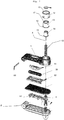
- FIGS. 7 to 10 are an exploded view, cross-sectional and longitudinal sectional views and a top view of an antitheft device according to an alternative embodiment wherein one of the arms contains a cartridge (50) filled with a marking substance.
- This substance may be an indelible ink, possibly under pressure.
- the cartridge (50) breaks and releases its content on the protected article, thereby removing its value permanently, but also on the hands of the thief.
- the ink capsule (50) is transparent to allow visibility of the ink.
- the cartridge (50) may also contain an odorous substance, for example a foul-smelling liquid, facilitating the identification of the thief and the provision of a presumption of attempted theft.
- an odorous substance for example a foul-smelling liquid
- the cartridge (50) is transparent to sensitize people tempted to commit fraud of the consequences of their act. It is protected by a transparent blade (51) and rests on a cradle (52).
- the second arm (2) incorporates an electromagnetic element (52) interacting with the antenna of the detection gantries placed at the entrances and exits of the magazine.
- the two arms (1, 2) are articulated by an axis (54).
- the figure 11 represents another variant embodiment of an antitheft device for fabrics or clothing.
- the inner surfaces of the arms (1, 2) have complementary surface elements (55, 56) to enhance the holding of an article having a thin, deformable area such as a fabric or garment.
- These surface elements have protuberances (55) of geometry complementary to the geometry of the recesses (56) provided on the inner surface of the opposite arm.
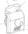
- FIGS 12 and 13 represent top views of a lock with a window (57) transparent and this lock protecting an article.
- the body of the lock can be either totally transparent or colored in the mass, with a window (57) passing through one of the arms (1) to allow the reading of information printed on the packaging (58) of the article to protect.
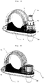
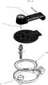
- FIGS. 14 and 15 represent top views of a lock for the protection of bottles.
- One of the arms (1) has an arcuate shape with a semicircular section, a radius corresponding to the outer radius of a bottle neck for example.
- the other arm (2) has a cradle (59) of a complementary profile. When the lock is closed, it determines a tubular space (60) can enclose a cylindrical portion of an article to protect.
- the various anti-theft devices can be grouped to form a set of locks, distinguished by a color code, for example by the color of the plastic or a colored pellet.
- FIGS. 16 to 18 represent views of another variant of implementation of the invention respectively from the front, in the open position, and from the rear, for securing against theft of articles presented under plastic shells with a top portion having a slot for hanging on the rods of a display.
- the device consists of two parts (1, 2) of rectangular shape, connected by an axis (53).
- One of the parts (1) is provided with the retractable elements (12 to 14) for the displacement of the needle (4) between the retracted position, where its end is set back with respect to the inner surface of the part ( 1), and a locking position where it passes through the blister of the article and enters the locking member (5) through a hole (72) provided in the second part (2).
- the inner surfaces of the rectangular portions (1, 2) have complementary zones (71) for blocking the fastening slot of the blisters.
- the upper part of the device has an area (70) provided with a slot (73) having the general shape of the attachment cutout provided with the blisters.
- the blister is introduced when the two parts (1, 2) are open and the needle (4) retracted.
- the clipping slit of the blister is then positioned in the complementary zone (71), and the two parts (1, 2) are closed.
- the needle (4) is then pressed by pressing on the retractable parts (12 to 14) until the end of the needle is inserted into the ball lock system (5).
- FIGS. 19 to 22 represent views of another variant embodiment of the invention, with an indexed coding.
- This variant makes it possible to highlight an encoding related to the value of the secure object. Indeed thieves replace the barcode label on the bottle by a barcode label of a bottle of a lower price. This flight tip is very difficult to track in the box, a secure marking bottle by a barcode label of a bottle of a lower price. This trick flight is very difficult to detect in cash, a secure marking on the lock associating a number (s) or letter (s) in relation to the value of the object (example: coding 1 -> price between 1 and 10 EUROS / coding 2 - price between 10 and 20 EUROS etc ...) allows the cashier to have an immediate relationship between the actual value of the bottle and the price related to the barcode. If the bottle goes to 9 euros and the coding is 4 (price between 30 and 40 euro).
- the upper movable body must be necessarily transparent.
- the knob and the coding ring being free to rotate, we have the possibility when the device is unlocked to be able to freely manipulate (in rotation) the coding ring. Depending on the desired coding, turn the ring until the marking is vertical to the coding window.
- This example relates to an anti-theft device for bottles, but the proposed solution is not limited to this application, but more generally applies to any application of a needle lock operable by retractable cages.
- the portion (1) is transparent to avoid the masking of the capsule surrounding the neck of the bottle.
- This variant relates to the fact that the tubular wall of the outer cage (12) has a cutout (90) extending in the example described over an angular width of about 40 degrees.
- the intermediate cage (13) carries markings distributed on the outer surface of the tubular wall, in the example describes a series of numbers, characters, signs or colors.
- the marking made on this ring can in particular give an indication of the size of a garment by combining the lettering S / M / L / X / XL / XXL, or tariff range, or promotion.
- the intermediate cage When the device is in the open position, the intermediate cage can be moved angularly to match one of the markings of the intermediate cage with the cutout (90) of the outer cage.
- the lower front surface (91) of the intermediate cage (14), and more precisely of its annular edge, has one or more indexing teeth (92). These indexing teeth (92) cooperate with a notched surface (93) provided on an annular zone of the floor of the portion (1).
- the outer cage (12) has a slotted tubular skirt, forming tabs (94 to 96) whose lower end is provided with hooks (97 to 99).
- This part (1) has a housing whose tubular skirt has ribs (101) whose bottom has slots (100). The outer cage (12) is thus clipped into the part (1).
- the figure 23 another variant of an anti-theft device an indexing wheel.
- the operator moves the wheel (110) by turning it to reach the requested size.
- This wheel is an integral part of the upper mobile subassembly (1), having a window (112) cut to allow reading of one of the marks affixed to the wheel (110).
- a system of serrations (111) between the rotatable part and its housing prevents the wheel from turning unexpectedly.
- the figure 24 is an exploded view of another alternative embodiment of a lock for the protection of hanging articles, packaged in the form of "blister" (trade name).
- This variant has two parts (1, 2), one of which is provided with a tilting hook (120) in order to be able to exit the spindle more easily and without risk of breaking the hook.
- the articulation of the hook (120) also prevents it from producing a lever effect that can weaken the device.
- This hook (120) is hinged relative to the portion (1) with two pivots (121, 122) also ensuring the articulation between the first and the second portion (1, 2).
- the device has on the inner surface of one of the parts (2), two retractable pins (123, 124) mounted on springs (125, 126). These pins (123, 124) make it possible to set up blisters having hook holes of different shapes and thicknesses and to adapt the size of the cavity formed between the two parts to the configuration of the article to be protected. without unnecessary game.
- the shape of the standard hook allowed the passage of three pawns, which is not the case for other forms of hooked (round hole or triangular).
- the retractable side pegs (123, 124) allow positioning of a wide variety of hook shapes.
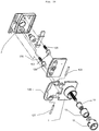
- FIGS. 25 to 28 represent views of another alternative embodiment of the invention, for the protection of articles such as shoes, lingerie articles, articles having a closed tube, etc.
- one of the parts (2) has a housing (131) receiving the end of a loop (130) made of a material resistant to cutting, including a steel buckle.
- the opposite end of this loop (130) has a bore (132) which can be traversed by the needle (4).
- This device uses the same locking base as the other variants, and allows you to adapt the lock with a minimum of technical changes to the protection of a wide range of items.
- the loop may have a "U" shape as shown in the Figures 25 and 26 , or even more elaborate forms, as represented in figure 27 and 28 , for example a shape with a loop (133) of reduced width extended by a bridge (134).
- FIGS. 29 to 30 represent views of another variant of implementation of the invention with enhanced security, respectively represented in the locked position and in the unlocked position.
- the vertical subassembly consisting of the main feeder (135), the ball cage (136) and the balls ( 137, 138) can not descend under the action of the lower magnet (139). The descent of this subassembly releases the pressure exerted on the nail by the balls (137, 138).
- the number of lateral weights can be set between 1 and N, and a regular distribution or not to enhance security.
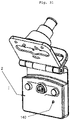
- the figure 31 represents a view of an alternative embodiment of a lock with an alarm.
- One of the parts (2) contains an electronic circuit integrated in the body, with a power supply and a sound generator.
- a probe (140) detects the closure of the device and the support of a protected article between the two parts (1, 2). The activation of the alarm is done when the device is closed. In the open position, it is in standby, until a first closing, activating the alarm. In case of forcing of the opening, the probe (140) is released and triggers the alarm.
- the deactivation under the control of the hostess is carried out by the detection of a magnetic field or a remote deactivation means.
- This circuit would be equipped with a probe allowing that during the introduction of the blister, the pressure exerted by the closure of the moving part and the blister activates the alarm via the probe. During the attempted break-in either by tearing off the blister or attempting to tear off the nail the probe is released and triggers the alarm
- the figure 31 shows a view of another alternative embodiment of a lock with an annular coil (150).
- One of the parts (2) has a disc shape, to receive a large annular coil (150), to increase the efficiency of the detection.
- the invention also relates to an anti-theft system constituted by a plurality of devices according to claim 1 and comprising a locking system common to a range of products, and a plurality of components forming variable first and second parts of geometry.
- the locking system is constituted by a first assembly comprising the nestable cages (12 to 14) and the nail (4), and a second assembly constituted by the locking system of the nail by balls.
- the first set may consist of a clipping component on one of the parts.
- the second set may also consist of a clip-on component on the opposite side.
- This solution reduces tooling costs to provide a wide range of anti-theft products.
Landscapes
- Physics & Mathematics (AREA)
- Engineering & Computer Science (AREA)
- Automation & Control Theory (AREA)
- Computer Security & Cryptography (AREA)
- Electromagnetism (AREA)
- General Physics & Mathematics (AREA)
- Multimedia (AREA)
- Burglar Alarm Systems (AREA)
Description
La présente invention concerne le domaine des dispositifs antivol destinés à sécuriser des articles en libre distribution. La solution la plus répandue pour protéger les articles est sans conteste le système de portique électronique avec étiquetage associé.The present invention relates to the field of antitheft devices for securing articles in free distribution. The most common solution for protecting items is undoubtedly the electronic gantry system with associated labeling.
Ces étiquetages utilisent des dispositifs munis d'un moyen interagissant avec un portique équipant les zones de sorties en dehors des caisses, et déclenchant une alarme lorsqu'un chaland tente de sortir du lieu de vente sans avoir payé l'article auquel le dispositif antivol est fixé.These labels use devices equipped with a means interacting with a gantry equipping the exit areas outside the crates, and triggering an alarm when a barge tries to leave the place of sale without having paid the article to which the anti-theft device is fixed.
La caissière dispose d'un déverrouilleur permettant de retirer le dispositif de l'article lors du passage en caisse.The cashier has an unlocker to remove the device of the article during the checkout.
Les dispositifs antivols sont configurés selon la géométrie et la nature de l'article à protéger. La présente invention concerne plus particulièrement des antivols destinés à protéger des articles vestimentaires tels que des chaussures, des articles de maroquinerie, des tissus, des accessoires de modes, des sous-vêtements, etc. sans que cette liste ne soit limitative.The anti-theft devices are configured according to the geometry and nature of the article to be protected. The present invention relates more particularly to anti-theft devices for protecting clothing articles such as shoes, leather goods, fabrics, fashion accessories, undergarments, etc. without this list being exhaustive.
Pour ce type d'article, il est connu dans l'état de la technique de prévoir un antivol formé de deux parties. L'une des parties présente une pointe pouvant traverser un trou de l'article, ou perforer un tissu. Cette pointe vient se loger dans une cavité prévue sur la partie complémentaire qui assure sont verrouillage. Dans ce cas, le verrouillage de la pointe empêche l'ouverture de l'antivol. Cette cavité comporte un système de verrouillage qui maintient fermement la pointe, lorsqu'elle est engagée dans la deuxième partie. Sa libération n'est possible qu'avec un déverrouilleur spécifique.For this type of article, it is known in the state of the art to provide a lock consisting of two parts. One of the parts has a tip that can pass through a hole in the article, or perforate a tissue. This tip is housed in a cavity provided on the complementary part which ensures locking. In this case, locking the tip prevents the opening of the lock. This cavity has a locking system that firmly holds the tip, when engaged in the second part. Its release is only possible with a specific unlocker.
On connaît en particulier la demande de brevet américain
On connaît aussi la demande de brevet internationale
On connaît encore le brevet
La demande de brevet
On connaît encore le brevet
L'élément male est une aiguille électriquement conductrice et conique sur toute sa longueur et ledit élément femelle est constitué par un boîtier dont le couvercle comporte un trou et dans lequel une plaquette électriquement isolante comporte un trou dans le même axe que le trou et d'un diamètre légèrement supérieur au plus grand diamètre de l'aiguille. L'extrémité du conducteur étant reliée à un point de contact de la plaquette. L'autre extrémité du conducteur est reliée à un second point de contact de la plaquette par l'aiguille et deux fils électriquement conducteurs fixés tangentiellement sur la plaquette de manière à être mis en contact mécanique et électrique avec l'aiguille quand elle pénètre dans les trous.The male element is an electrically conductive and conical needle along its entire length and said female element is constituted by a housing whose lid comprises a hole and in which an electrically insulating plate has a hole in the same axis as the hole and a diameter slightly greater than the largest diameter of the needle. The end of the conductor being connected to a point of contact of the wafer. The other end of the conductor is connected to a second point of contact of the wafer by the needle and two electrically conductive wires fixed tangentially on the wafer so as to be brought into mechanical and electrical contact with the needle when it enters the wafers. holes.
On connaît également un dispositif antivol du document
On connaît enfin des dispositifs antivol des documents
Les solutions de l'art antérieur ne sont pas pleinement satisfaisantes.The solutions of the prior art are not fully satisfactory.
Le premier inconvénient est que la pointe destinée à traverser l'article à protéger est invasive et peut blesser l'utilisateur lors de la mise en place ou du retrait du dispositif sur un article, notamment dans le cas où la pointe affleure de la surface du dispositif en position d'ouverture.The first disadvantage is that the tip intended to cross the article to be protected is invasive and can injure the user when setting up or removing the device on an article, especially in the case where the tip is flush with the surface of the device in the open position.
Le deuxième inconvénient, pour certaines solutions, est que cette pointe effectue une trajectoire courbe dans laquelle elle n'est en face de l'orifice de réception que lorsque les bras sont bien positionnés. Le moindre effort latéral empêche la pénétration de la pointe dans l'orifice de réception.The second disadvantage, for some solutions, is that this tip performs a curved path in which it is opposite the receiving orifice when the arms are well positioned. The slightest lateral force prevents penetration of the tip into the receiving hole.
Le troisième inconvénient est que ces solutions de l'art antérieur sont limités à un type d'articles, et ne présente pas de flexibilité pour une utilisation plus universelle, pour des articles d'épaisseur ou de configuration différentes.The third disadvantage is that these solutions of the prior art are limited to one type of article, and does not have flexibility for more universal use, for articles of different thickness or configuration.
Un quatrième inconvénient est la vulnérabilité du dispositif de l'art antérieur en cas de choc brutal sur le dispositif. Dans ce cas, il est habituel que le moyen de verrouillage libère de manière inopportune l'aiguille, ce qui permet à un voleur de retirer le dispositif et ainsi contrer les dispositifs d'alarme prévus dans le magasin.A fourth drawback is the vulnerability of the device of the prior art in the event of a sudden shock on the device. In this case, it is customary for the locking means to unintentionally release the needle, which allows a thief to remove the device and thus counter the alarm devices provided in the magazine.
Afin de remédier aux trois premiers inconvénients, la présente invention concerne selon son acception la plus générale un dispositif antivol destiné à être attaché à un article en vente libre, formé par deux parties dont l'une comporte un moyen d'interaction à distance avec une borne de détection du passage d'un tel dispositif, lesdites parties étant articulées par une charnière pour permettre un débattement entre une position de protection dans laquelle elle interagissent avec une partie de l'article à protéger pour empêcher la séparation du dispositif antivol et l'article, et une position de libération dans laquelle elle permettent le retrait de l'article, l'une des parties présentant à l'extrémité opposée à ladite charnière mobile aiguille mobile selon une direction perpendiculaire au plan médian du dispositif, l'autre partie comportant un logement pour recevoir ladite aiguille, le logement comportant des moyens de verrouillage configurés pour permettre la libération de ladite aiguille à l'aide d'un déverrouilleur, caractérisé en ce qu'il en ce que ladite première partie présentant trois cages emboitées permettant le déplacement de ladite aiguille entre une position escamotée où la pointe de ladite aiguille ne dépasse pas la surface intérieure de la première partie, et une position sortie où ladite aiguille est engagée dans le logement complémentaire lorsque le dispositif est en position fermée.In order to remedy the first three disadvantages, the present invention relates, according to its most general meaning, to an antitheft device intended to be attached to an article sold over the counter, formed by two parts, one of which includes means for remote interaction with a device. detection terminal of the passage of such a device, said parts being articulated by a hinge to allow a movement between a protective position in which it interacts with a portion of the article to be protected to prevent the separation of the antitheft device and the article, and a release position in which it allows the withdrawal of the article, one of the parties having at the opposite end to said moving needle hinge in a direction perpendicular to the median plane of the device, the other part having a housing for receiving said needle, the housing having locking means configured to allow the release of said needle to using an unlocker, characterized in that said first portion having three nested cages for moving said needle between a retracted position where the tip of said needle does not exceed the inner surface of the first part , and an output position where said needle is engaged in the complementary housing when the device is in the closed position.
De préférence la cage extérieure présente un volume creux intérieure correspondant au volume extérieur de la cage intermédiaire, ladite cage intermédiaire présentant un volume creux intérieure correspondant au volume extérieur de la cage intérieur, la hauteur de la cage intermédiaire étant configurées pour ne pas dépasser la surface frontale supérieure de la cage extérieure, la hauteur de la cage intérieure étant configurées pour ne pas dépasser la surface frontale supérieure des cage extérieure et intermédiaire en position de verrouillage.Preferably the outer cage has an inner hollow volume corresponding to the external volume of the intermediate cage, said intermediate cage having an inner hollow space corresponding to the outer volume of the inner cage, the height of the intermediate cage being configured not to exceed the surface upper end of the outer cage, the height of the inner cage being configured not to exceed the upper end surface of the outer and middle cage in the locking position.
Selon une variante, le moyen de verrouillage est constitué par au moins une bille repoussée par un ressort vers le fond du logement destiné à recevoir l'aiguille, ledit logement présentant une forme tronconique destiné à provoquer un coincement de la bille contre l'aiguille, ladite bile étant apte à interagir avec un moyen de déverrouillage pour s'opposer à l'action dudit ressort.According to a variant, the locking means is constituted by at least one ball driven by a spring towards the bottom of the housing intended to receive the needle, said housing having a frustoconical shape intended to cause jamming of the ball against the needle, said bile being able to interact with an unlocking means to oppose the action of said spring.
Avantageusement, le moyen de verrouillage comprend en outre un moyen de blocage latéral dudit logement de forme tronconique, ledit moyen de blocage latéral étant apte à interagir avec un moyen de déverrouillage pour libérer le déplacement axial dudit logement.Advantageously, the locking means further comprises lateral locking means of said frustoconical shaped housing, said lateral locking means being adapted to interact with an unlocking means to release the axial displacement of said housing.
Selon une première variante, le moyen de verrouillage est constitué par au moins une bille repoussée par un ressort vers le fond du logement destiné à recevoir l'aiguille, ledit logement présentant une forme conique destiné à provoquer un coincement de la bille contre l'aiguille, ladite bile étant apte à interagir avec un moyen de déverrouillage pour s'opposer à l'action dudit ressort.According to a first variant, the locking means is constituted by at least one ball driven by a spring towards the bottom of the housing for receiving the needle, said housing having a conical shape intended to cause jamming of the ball against the needle. said bile being able to interact with an unlocking means to oppose the action of said spring.
Selon une deuxième variante, le moyen de verrouillage est constitué par une lame configurée pour empêcher le déplacement de l'aiguille au repos et interagir avec un moyen de déverrouillage pour libérer ladite aiguille.In a second variant, the locking means is constituted by a blade configured to prevent movement of the needle at rest and interact with an unlocking means to release said needle.
Avantageusement, lesdites première et deuxième parties sont configurées pour délimiter une fenêtre transversale.Advantageously, said first and second parts are configured to delimit a transverse window.
Selon un mode de réalisation particulier, les extrémités desdites première et deuxième parties sont configurées pour former une surface de retenue de l'article à protéger.According to a particular embodiment, the ends of said first and second parts are configured to form a retaining surface of the article to be protected.
Afin de répondre également au quatrième inconvénient susvisé, ladite deuxième partie est prolongée dans l'axe de l'aiguille par un amortisseur.To also meet the fourth disadvantage referred to above, said second portion is extended in the axis of the needle by a damper.
Selon une première variante, ledit amortisseur est constituée par une pièce déformable élastiquement.According to a first variant, said damper is constituted by an elastically deformable piece.
Selon une deuxième variante, ledit amortisseur est constituée par une pièce mobile axialement et amortie par un ressort.According to a second variant, said damper is constituted by a movable part axially and damped by a spring.
L'invention concerne aussi des moyens pour renforcer l'efficacité de la protection.The invention also relates to means for enhancing the effectiveness of the protection.
Selon une première variante, l'une desdites parties contient une capsule remplie d'une substance marquante.According to a first variant, one of said parts contains a capsule filled with a marking substance.
Selon une deuxième variante, l'une desdites parties présente au moins une zone transparente.According to a second variant, one of said parts has at least one transparent zone.
Selon une troisième variante, l'une desdites parties au moins présente sur sa surface interne un état de surface renforçant l'interaction mécanique avec l'article à protéger.According to a third variant, at least one of said parts has on its inner surface a surface state reinforcing the mechanical interaction with the article to be protected.
Selon une quatrième variante, lesdites parties présentent sur leurs surfaces intérieures des éléments de surface complémentaires pour renforcer la coopération avec un article à protéger fin et déformable.According to a fourth variant, said parts have on their inner surfaces complementary surface elements to enhance cooperation with a thin and deformable article to protect.
Selon une cinquième variante, lesdites parties présentent une forme arquée pour entourer une zone cylindrique d'un article à protéger.According to a fifth variant, said portions have an arcuate shape to surround a cylindrical zone of an article to be protected.
Avantageusement, le dispositif antivol selon l'invention constitue l'un des éléments d'une série de dispositifs antivol se distinguant les uns des autres par un code coloré.Advantageously, the antitheft device according to the invention is one of the elements of a series of antitheft devices distinguished from each other by a color code.
L'invention concerne aussi un système formé par une pluralité de tels dispositifs antivol, comportant un système de verrouillage commun à une gamme de produits, et une pluralité de composants formant des premières et deuxièmes parties de géométrie variables, chacun desdits dispositifs de verrouillage étant constitué par un premier ensemble comprenant les cages emboitables (12 à 14) et le clou (4), et un deuxième ensemble constitué par le système de blocage du clou par des billes.The invention also relates to a system formed by a plurality of such antitheft devices, comprising a locking system common to a range of products, and a plurality of components forming first and second variable geometry parts, each of said locking devices consisting of by a first assembly comprising the nestable cages (12 to 14) and the nail (4), and a second assembly constituted by the locking system of the nail by balls.
L'invention sera mieux comprise à la lecture de la description qui suit, se référant aux dessins annexés concernant des exemples non limitatif de réalisation où :
- les
figures 1 et 2 représentent des vues du dispositif respectivement en position ouverte et en position fermée - les
figures 3 et 4 représentent des vues en coupe du dispositif fermé respectivement en position déverrouillée et en position verrouillées - les
figures 5 et 6 représentent des vues en coupe du dispositif fermé selon deux alternatives de réalisation - les
figures 7 à 10 représentent une vue éclatée, des vues en coupe transversale et en coupe longitudinale et une vue de dessus d'un dispositif antivol selon une variante de réalisation où l'un des bras contient une cartouche d'encre - la
figure 11 représente une autre variante de réalisation d'un antivol destiné à des tissus ou vêtements - les
figures 12 et 13 représentent des vues de dessus d'un antivol avec une fenêtre transparente et de cet antivol protégeant un article - les
figures 14 et 15 représentent des vues de dessus d'un antivol pour la protection de bouteilles. - Les
figures 16 à 18 représentent des vues d'une autre variante de mise en oeuvre de l'invention - Les
figures 19 à 22 représentent des vues d'une autre variante de mise en oeuvre de l'invention, avec un codage indexé - La
figure 23 représente une vue éclatée d'une autre variante de réalisation d'un antivol avec une molette d'indexation - La
figure 24 représente une vue éclatée d'une une autre variante de réalisation d'un antivol pour la protection d'articles suspendus - Les
figures 25 à 28 représentent des vues d'une autre variante de mise en oeuvre de l'invention, pour la protection d'articles avec une boucle. - Les
figures 29 à 30 représentent des vues d'une autre variante de mise en oeuvre de l'invention avec une sécurité renforcée - La
figure 31 représente une vue d'une une autre variante de réalisation d'un antivol avec une alarme - La
figure 32 représente une vue d'une une autre variante de réalisation d'un antivol avec bobine annulaire.
- the
Figures 1 and 2 represent views of the device respectively in the open position and in the closed position - the
Figures 3 and 4 represent sectional views of the closed device respectively in the unlocked position and in the locked position - the
Figures 5 and 6 represent sectional views of the closed device according to two alternative embodiments - the
Figures 7 to 10 are an exploded view, cross-sectional and longitudinal sectional views and a top view of an antitheft device according to an alternative embodiment wherein one of the arms contains an ink cartridge - the
figure 11 represents another variant embodiment of an anti-theft device for fabrics or clothing - the
Figures 12 and 13 represent top views of a lock with a transparent window and this lock protecting an item - the
Figures 14 and 15 represent top views of a lock for the protection of bottles. - The
Figures 16 to 18 represent views of another alternative embodiment of the invention - The
Figures 19 to 22 represent views of another alternative embodiment of the invention, with an indexed coding - The
figure 23 represents an exploded view of another embodiment of an antitheft device with an indexing wheel - The
figure 24 is an exploded view of another alternative embodiment of a lock for the protection of hanging articles - The
Figures 25 to 28 represent views of another alternative embodiment of the invention, for the protection of articles with a loop. - The
Figures 29 to 30 represent views of another alternative embodiment of the invention with enhanced security - The
figure 31 represents a view of an alternative embodiment of a lock with an alarm - The
figure 32 shows a view of another alternative embodiment of a lock with annular coil.
Les
Il est formé par deux bras (1, 2), reliés par une articulation (3). Ces bras (1, 2) sont de forme généralement parallélépipédiques, légèrement arqués pour former, en position fermée, une cavité transversale (6). Le premier bras (1) est prolongé perpendiculairement par une aiguille (4). L'autre bras (2) est pourvu d'un prolongement perpendiculaire (5).It is formed by two arms (1, 2), connected by a hinge (3). These arms (1, 2) are of generally parallelepipedal shape, slightly arched to form, in the closed position, a transverse cavity (6). The first arm (1) is extended perpendicularly by a needle (4). The other arm (2) is provided with a perpendicular extension (5).
L'extrémité (7) du premier bras (1) forme un plateau venant au contact d'un plateau complémentaire (8) prévu à l'extrémité du deuxième bras (2) lorsque le dispositif est en positon fermé.The end (7) of the first arm (1) forms a plate coming into contact with a complementary plate (8) provided at the end of the second arm (2) when the device is in closed position.
Ce dispositif peut être utilisé pour différents types d'articles :
- des articles minces présentant des oeillets, tels que des chaussures, des accessoires de mode, des vêtements et sous-vêtements, etc. : dans ce cas, l'aiguille (4) traverse un des oeillets de l'article
- des articles textiles : dans ce cas, l'aiguille (4) perfore une zone peu fragile de l'article
- des articles présentant un manche ou une lanière : dans ce cas, le dispositif est refermé pour loger le manche ou la lanière dans la fenêtre (6). Cette fenêtre peut présenter à cet effet une section rectangulaire, ou ronde, ou de toute autre forme adaptée.
- thin items with eyelets, such as shoes, fashion accessories, clothing and underwear, etc. : in this case, the needle (4) passes through one of the eyelets of the article
- textile articles: in this case, the needle (4) perforates a fragile area of the article
- articles having a handle or a strap: in this case, the device is closed to accommodate the handle or the strap in the window (6). This window may have for this purpose a rectangular section, or round, or any other suitable form.
Les
En position déverrouillée, l'aiguille (4) est repoussée en position escamotée par un ressort (10) qui vient en appui contre un épaulement annulaire (11) prévu au niveau de la tête de l'aiguille (4). Ce ressort s'appuie du coté opposé sur la flasque (7) formant l'extrémité du premier bras (1).In the unlocked position, the needle (4) is pushed into the retracted position by a spring (10) which abuts against an annular shoulder (11) provided at the head of the needle (4). This spring is supported on the opposite side on the flange (7) forming the end of the first arm (1).
L'aiguille (4) est lisse, pour éviter d'abimer l'article protégé lorsqu'elle traverse un tissu. Elle peut aussi présenter des cannelures pour améliorer le maintien par les billes de verrouillage.The needle (4) is smooth, to avoid damaging the protected article as it passes through a fabric. It can also have grooves to improve the maintenance by the locking balls.
L'aiguille est actionnée par un ensemble de trois cages (12, 13, 14) escamotables et emboitées.The needle is actuated by a set of three cages (12, 13, 14) retractable and nested.
La première cage (12) est fixe. La cage intermédiaire (13) est mobile en translation axiale par rapport à la première cage (12). La cage intérieure (14) est mobile en translation axiale par rapport à la cage intermédiaire (14).The first cage (12) is fixed. The intermediate cage (13) is movable in axial translation with respect to the first cage (12). The inner cage (14) is movable in axial translation relative to the intermediate cage (14).
La première cage (12) présente une forme cylindrique. Elle présente la plus grande section. Elle est fixe et solidaire de la flasque (7). Elle présente une surface intérieure tubulaire, assurant le guidage de la deuxième cage (13), mobile en translation axiale par rapport à la première cage (12).The first cage (12) has a cylindrical shape. It has the largest section. It is fixed and integral with the flange (7). It has a tubular inner surface, guiding the second cage (13), movable in axial translation relative to the first cage (12).
L'extrémité supérieure de la première cage présente un épaulement intérieur annulaire (15) réduisant la section et délimitant un passage pour la deuxième cage cylindrique (13).The upper end of the first cage has an annular inner shoulder (15) reducing the section and delimiting a passage for the second cylindrical cage (13).
Cette deuxième cage (13) cylindrique présentant également une surface intérieure tubulaire, assurant le guidage de la cage intérieure (14).This second cylindrical cage (13) also having a tubular inner surface, guiding the inner cage (14).
La cage intermédiaire (13) présente à sa partie inférieure un épaulement extérieur annulaire (16) d'une section extérieure complémentaire à la section intérieure de la cage (12), pour assurer le déplacement et le guidage. Cet épaulement (16) vient en butée contre l'épaulement annulaire intérieure (15) de la cage extérieure (12) et empêche le retrait de la deuxième cage par rapport à la première cage (12).The intermediate cage (13) has at its lower part an annular outer shoulder (16) of an outer section complementary to the inner section of the cage (12), to provide movement and guidance. This shoulder (16) abuts against the inner annular shoulder (15) of the outer cage (12) and prevents removal of the second cage relative to the first cage (12).
La deuxième cage (13) présente également à sa partie supérieure un épaulement intérieur annulaire (17) réduisant la section et délimitant un passage pour d'une troisième cage tronconique (14) présentant à sa partie inférieure un épaulement annulaire extérieur (18) limitant le déplacement et empêchant le retrait de la troisième cage par rapport à la deuxième cage (13).The second cage (13) also has at its upper part an annular inner shoulder (17) reducing the section and delimiting a passage for a third frustoconical cage (14) having at its lower part an outer annular shoulder (18) limiting the moving and preventing removal of the third cage from the second cage (13).
Le fond de la troisième cage (14) est fermée par un fond (20) constituant une butée intérieure contre laquelle vient s'appuyer la tête de l'aiguille (4), et dont la surface extérieure forme une zone d'appui permettant à l'utilisateur de repousser l'aiguille dans son réceptacle (5).The bottom of the third cage (14) is closed by a bottom (20) constituting an inner abutment against which the head of the needle (4) abuts, and whose outer surface forms a bearing zone allowing the user pushing the needle into its receptacle (5).
Les courses des deux cages intermédiaire et intérieure (13, 14) sont sensiblement utiles, de telle sorte que l'amplitude du déplacement de la pointe de l'aiguille (14) est environ deux fois supérieure à la variation de hauteur du bouton de verrouillage, entre la position d'ouverture et la position verrouillée. Ceci permet de réduire l'encombrement du dispositif, tout en préservant une course utile permettant un verrouillage efficace.The strokes of the two intermediate and inner cages (13, 14) are substantially useful, so that the amount of displacement of the tip of the needle (14) is about two times greater than the variation in height of the locking knob , between the open position and the locked position. This reduces the size of the device, while preserving a useful stroke for effective locking.
Bien sur, l'invention pourrait aussi prévoir un nombre plus élevé de cages mobiles.Of course, the invention could also provide a higher number of mobile cages.
En exerçant un effort axial sur le fond de la troisième cage (14), on provoque l'engagement des trois cages les unes dans les autres, ce qui réduit leur hauteur et permet à l'aiguille de dépasser la surface de la zone frontale (7) du premier bras pour s'engager dans le réceptacle (5) prévue à l'extrémité du deuxième bras (2).By exerting an axial force on the bottom of the third cage (14), the three cages are engaged in each other, which reduces their height and allows the needle to pass the surface of the frontal zone ( 7) of the first arm to engage the receptacle (5) provided at the end of the second arm (2).
Ce réceptacle présente un logement tronconique (21) contenant trois billes (22, 23) réparties avec un décalage de 120° autour de l'axe médian.This receptacle has a frustoconical housing (21) containing three balls (22, 23) distributed with an offset of 120 ° around the central axis.
Ces billes (22, 23) sont repoussées en direction du fond (26) de ce logement conique (21) par un ressort (25) prenant appui sur le fond du réceptacle (5). Ces billes viennent bloquer le déplacement de l'aiguille (4) par l'effet de coincement résultant de la composante radiale de l'action des billes (22, 23) sur la paroi intérieure du logement tronconique (21).These balls (22, 23) are pushed towards the bottom (26) of this conical housing (21) by a spring (25) bearing on the bottom of the receptacle (5). These balls block the displacement of the needle (4) by the wedging effect resulting from the radial component of the action of the balls (22, 23) on the inner wall of the frustoconical housing (21).
Les billes (22, 23) sont métalliques et éventuellement magnétiques. Lorsque déverrouilleur comporte un aimant puissant ou un électroaimant est approché du fond du réceptacle (5), la force magnétique s'oppose à l'effet du ressort (25), ce qui réduit l'effet de coincement de l'aiguille (4) et permet de libérer l'aiguille, et donc de déverrouiller puis d'ouvrir le dispositif.The balls (22, 23) are metallic and possibly magnetic. When an unlocker has a strong magnet or an electromagnet is brought near the bottom of the receptacle (5), the magnetic force opposes the effect of the spring (25), which reduces the jamming effect of the needle (4) and allows to release the needle, and thus to unlock and open the device.
Pour éviter que des chocs axiaux, exercés sur le fond du réceptacle, en tapant brutalement le dispositif sur une surface dure, ne vienne inopinément déplacer les billes et libérer l'aiguille, différentes solutions sont proposées.To prevent axial shocks, exerted on the bottom of the receptacle, by suddenly tapping the device on a hard surface, unexpectedly move the balls and release the needle, different solutions are proposed.
La première consiste à orienter l'axe longitudinal défini par l'aiguille (4) et le réceptacle (5) selon un angle par rapport au plan transversal du dispositif par exemple un angle de 10 à 35 degrés par rapport à la perpendiculaire, de façon à ce qu'un choc frontal n'interviennent pas dans l'axe de déplacement des billes (22, 23).The first is to orient the longitudinal axis defined by the needle (4) and the receptacle (5) at an angle relative to the transverse plane of the device, for example an angle of 10 to 35 degrees relative to the perpendicular, so that a frontal impact does not intervene in the axis of movement of the balls (22, 23).
Une autre solution est décrite en référence aux
Le fond du réceptacle (5) est prolongé par une zone amortie. Il s'agit, dans l'exemple illustré par la
Une alternative illustrée par la
Les
Cette substance peut être une encre indélébile, éventuellement sous pression. En cas de tentative de destruction de l'antivol, par exemple avec une pince coupante utilisée pour casser le bras (1), ou un levier inséré entre l'article et le bras pour le forcer, la cartouche (50) se brise et libère son contenu sur l'article protégé, lui enlevant ainsi définitivement sa valeur, mais aussi sur les mains du voleur. La capsule d'encre (50) est transparente pour permettre la visibilité de l'encre.This substance may be an indelible ink, possibly under pressure. In the event of an attempt to destroy the lock, for example with a cutting pliers used to break the arm (1), or a lever inserted between the article and the arm to force it, the cartridge (50) breaks and releases its content on the protected article, thereby removing its value permanently, but also on the hands of the thief. The ink capsule (50) is transparent to allow visibility of the ink.
La cartouche (50) peut aussi contenir une substance odorante, par exemple un liquide d'odeur nauséabonde, facilitant l'identification du voleur et l'apport d'une présomption de tentative de vol.The cartridge (50) may also contain an odorous substance, for example a foul-smelling liquid, facilitating the identification of the thief and the provision of a presumption of attempted theft.
La cartouche (50) est transparente pour sensibiliser les personnes tentées de commettre une fraude des conséquences de leur acte. Elle est protégée par une lame transparente (51) et repose sur un berceau (52).The cartridge (50) is transparent to sensitize people tempted to commit fraud of the consequences of their act. It is protected by a transparent blade (51) and rests on a cradle (52).
Le deuxième bras (2) incorpore un élément électromagnétique (52) interagissant avec l'antenne des portiques de détection placés aux entrées et sorties du magasin. Les deux bras (1, 2) sont articulés par un axe (54).The second arm (2) incorporates an electromagnetic element (52) interacting with the antenna of the detection gantries placed at the entrances and exits of the magazine. The two arms (1, 2) are articulated by an axis (54).
La
Les surfaces intérieures des bras (1, 2) présentent des éléments de surface (55, 56) complémentaires pour renforcer le maintien d'un article présentant une zone fine et déformable telle qu'un tissu ou un vêtement.The inner surfaces of the arms (1, 2) have complementary surface elements (55, 56) to enhance the holding of an article having a thin, deformable area such as a fabric or garment.
Ces éléments de surface présentent des protubérances (55) de géométrie complémentaire à la géométrie des creux (56) prévues sur la surface intérieure du bras opposé.These surface elements have protuberances (55) of geometry complementary to the geometry of the recesses (56) provided on the inner surface of the opposite arm.
Les
Les
L'un des bras (1) présente une forme arquée avec une section en demi-cercle, d'un rayon correspondant au rayon extérieur d'un col de bouteille par exemple. L'autre bras (2) présente un berceau (59) d'un profil complémentaire. Lorsque l'antivol est fermé, il détermine un espace tubulaire (60) pouvant enserrer une partie cylindrique d'un article à protéger.One of the arms (1) has an arcuate shape with a semicircular section, a radius corresponding to the outer radius of a bottle neck for example. The other arm (2) has a cradle (59) of a complementary profile. When the lock is closed, it determines a tubular space (60) can enclose a cylindrical portion of an article to protect.
Les différents dispositifs antivols peuvent être regroupés pour former un ensemble d'antivols, se distinguant par un code couleur, par exemple par la couleur du plastique ou par une pastille colorée.The various anti-theft devices can be grouped to form a set of locks, distinguished by a color code, for example by the color of the plastic or a colored pellet.
Les
Le dispositif est constitué de deux parties (1, 2) de forme rectangulaire, reliées par un axe (53).The device consists of two parts (1, 2) of rectangular shape, connected by an axis (53).
L'une des parties (1) est pourvue des éléments escamotables (12 à 14) pour le déplacement de l'aiguille (4) entre la position escamotée, où son extrémité se trouve en retrait par rapport à la surface intérieure de la partie (1), et une position de verrouillage où elle traverse le blister de l'article et pénètre dans l'organe de verrouillage (5) en passant par un trou (72) prévu dans la deuxième partie (2).
Les surfaces intérieures des parties rectangulaires (1, 2) présentent des zones complémentaires (71) pour le blocage de la fente d'accrochage des blisters.One of the parts (1) is provided with the retractable elements (12 to 14) for the displacement of the needle (4) between the retracted position, where its end is set back with respect to the inner surface of the part ( 1), and a locking position where it passes through the blister of the article and enters the locking member (5) through a hole (72) provided in the second part (2).
The inner surfaces of the rectangular portions (1, 2) have complementary zones (71) for blocking the fastening slot of the blisters.
La partie supérieure du dispositif présente une zone (70) pourvue d'une lumière (73) présentant la forme générale de la découpe d'accrochage dont sont pourvues les blisters.The upper part of the device has an area (70) provided with a slot (73) having the general shape of the attachment cutout provided with the blisters.
Le blister est introduit lorsque les deux parties (1, 2) sont ouvertes et l'aiguille (4) rétractée. On positionne alors la découpe d'accrochage du blister dans la zone complémentaire (71), et on referme les deux parties (1, 2). On enfonce ensuite l'aiguille (4) par une pression sur les parties escamotables (12 à 14), jusqu'à l'introduction de l'extrémité de l'aiguille dans le système de verrouillage à billes (5).The blister is introduced when the two parts (1, 2) are open and the needle (4) retracted. The clipping slit of the blister is then positioned in the complementary zone (71), and the two parts (1, 2) are closed. The needle (4) is then pressed by pressing on the retractable parts (12 to 14) until the end of the needle is inserted into the ball lock system (5).
Les
Cette variante permet de de mettre en évidence un codage en rapport avec la valeur de l'objet sécurisé. En effet les voleurs remplacent l'étiquette code barres sur la bouteille par une étiquette code barres d'une bouteille d'un prix inférieur. Cette astuce de vol étant très difficile à dépister en caisse, un marquage sécurisé bouteille par une étiquette code barres d'une bouteille d'un prix inférieur. Cette astuce de vol étant très difficile à dépister en caisse, un marquage sécurisé sur l'antivol associant un chiffre(s) ou une lettre(s) en rapport avec la valeur de l'objet (exemple : codage 1 -> prix compris entre 1 et 10 EUROS / codage 2 - prix compris entre 10 et 20 EUROS etc ...) permet à l'hôtesse de caisse d'avoir immédiatement un rapport entre la valeur réel de la bouteille et le prix lié au code barres. Si la bouteille passe à 9 euros et que le codage est 4 (prix compris entre 30 et 40 EUROS).This variant makes it possible to highlight an encoding related to the value of the secure object. Indeed thieves replace the barcode label on the bottle by a barcode label of a bottle of a lower price. This flight tip is very difficult to track in the box, a secure marking bottle by a barcode label of a bottle of a lower price. This trick flight is very difficult to detect in cash, a secure marking on the lock associating a number (s) or letter (s) in relation to the value of the object (example: coding 1 -> price between 1 and 10 EUROS / coding 2 - price between 10 and 20 EUROS etc ...) allows the cashier to have an immediate relationship between the actual value of the bottle and the price related to the barcode. If the bottle goes to 9 euros and the coding is 4 (price between 30 and 40 euro).
Pour cette solution technique le corps mobile supérieur doit être forcément transparent.For this technical solution the upper movable body must be necessarily transparent.
Le bouton et la bague de codage étant libre en rotation, nous avons la possibilité lorsque le dispositif est déverrouillé de pouvoir manipuler librement (en rotation) la bague de codage. Suivant le codage désiré, tourner la bague jusqu'à ce que le marquage se retrouve à la verticale de la fenêtre de codage.The knob and the coding ring being free to rotate, we have the possibility when the device is unlocked to be able to freely manipulate (in rotation) the coding ring. Depending on the desired coding, turn the ring until the marking is vertical to the coding window.
A ce stade, l'ensemble des codages restent visible. Après avoir positionné le dispositif sur la bouteille, la pression exercée sur le bouton pour engager le clou dans le verrou à billes va entrainer l'ensemble bouton/bague de codage vers le bas. Cette action permet au codage présélectionné d'être le seul visible par la fenêtre de codage pratiquée dans la bague inférieure.At this point, all the codings remain visible. After positioning the device on the bottle, the pressure exerted on the button to engage the nail in the ball lock will cause the button / encoder ring assembly downward. This action allows preselected coding to be the only one visible by the coding window made in the lower ring.
Malgré que la bague de codage ne soit plus accessible facilement, nous pouvions en exerçant une pression en rotation sur la zone bouton (verrouillée) réussir a changer le codage. Ce problème a été résolu en associant des dents (3 dents en relief à 120°) sur la bague de codage et une zone circulaire dentelée en creux dans le corps mobile transparent. En effet lors du verrouillage, la bague de codage se retrouve en pression contre le corps mobile transparent au niveau de la zone de denture aménagée dans les deux pièces. Cette association de pièces empêche une modification du codage après verrouillage.Although the coding ring was no longer easily accessible, we could exert a pressure in rotation on the button zone (locked) to change the coding. This problem has been solved by associating teeth (3 teeth in relief at 120 °) on the coding ring and a circular zone serrated hollow in the transparent moving body. Indeed during the locking, the coding ring is found in pressure against the transparent movable body at the tooth zone arranged in the two parts. This combination of parts prevents modification of the coding after locking.
Cet exemple concerne un dispositif antivol pour bouteilles, mais la solution proposée n'est pas limitée à cette application, mais s'applique plus généralement à toute application d'un antivol à aiguille actionnable par des cages escamotables. La partie (1) est transparente pour éviter le masquage de la capsule entourant le col de la bouteille.This example relates to an anti-theft device for bottles, but the proposed solution is not limited to this application, but more generally applies to any application of a needle lock operable by retractable cages. The portion (1) is transparent to avoid the masking of the capsule surrounding the neck of the bottle.
Cette variante porte sur le fait que la paroi tubulaire de la cage extérieure (12) présente une découpe (90) s'étendant dans l'exemple décrit sur une largeur angulaire d'environ 40 degrés.This variant relates to the fact that the tubular wall of the outer cage (12) has a cutout (90) extending in the example described over an angular width of about 40 degrees.
La cage intermédiaire (13) porte des marquages répartis sur la surface extérieure de la paroi tubulaire, dans l'exemple décrit une série de chiffres, de caractères, de signes ou de couleurs.The intermediate cage (13) carries markings distributed on the outer surface of the tubular wall, in the example describes a series of numbers, characters, signs or colors.
Le marquage réalisé sur cette bague peut notamment donner une indication sur la taille d'un vêtement en associant le lettrage S / M / L / X / XL / XXL, ou de gamme tarifaire, ou de promotion.The marking made on this ring can in particular give an indication of the size of a garment by combining the lettering S / M / L / X / XL / XXL, or tariff range, or promotion.
Lorsque le dispositif est en position ouverte, la cage intermédiaire peut être déplacée angulairement pour faire correspondre l'un des marquages de la cage intermédiaire avec la découpe (90) de la cage extérieure.When the device is in the open position, the intermediate cage can be moved angularly to match one of the markings of the intermediate cage with the cutout (90) of the outer cage.
Lorsque les cages (12 à 14) sont en position de verrouillage, l'un des marquages est visible à travers la fenêtre (90).When the cages (12 to 14) are in the locked position, one of the markings is visible through the window (90).
La surface frontale inférieure (91) de la cage intermédiaire (14), et plus précisément de sa bordure annulaire, présente une ou plusieurs dents (92) d'indexation. Ces dents d'indexation (92) coopèrent avec une surface crantée (93) prévue sur une zone annulaire du plancher de la partie (1).The lower front surface (91) of the intermediate cage (14), and more precisely of its annular edge, has one or more indexing teeth (92). These indexing teeth (92) cooperate with a notched surface (93) provided on an annular zone of the floor of the portion (1).
Dans cet exemple de réalisation, la cage extérieure (12) présente une jupe tubulaire fendue, formant des pattes (94 à 96) dont l'extrémité inférieure est munie de crochets (97 à 99).In this embodiment, the outer cage (12) has a slotted tubular skirt, forming tabs (94 to 96) whose lower end is provided with hooks (97 to 99).
Ces pattes assurent l'ancrage de la cage extérieure (12) sur la partie (1). Cette partie (1) présente un logement dont la jupe tubulaire présente des nervures (101) dont le fond présente des fentes (100). La cage extérieure (12) est ainsi enclipsée dans la partie (1).These tabs anchor the outer cage (12) on the part (1). This part (1) has a housing whose tubular skirt has ribs (101) whose bottom has slots (100). The outer cage (12) is thus clipped into the part (1).
La
Cette molette fait partie intégrante du sous-ensemble mobile supérieur (1), présentant une fenêtre (112) découpée pour permettre la lecture d'une des marques apposée sur la molette (110).This wheel is an integral part of the upper mobile subassembly (1), having a window (112) cut to allow reading of one of the marks affixed to the wheel (110).
Un système de dentelures (111) entre la partie mobile en rotation et son logement empêche la molette de tourner de manière intempestive.A system of serrations (111) between the rotatable part and its housing prevents the wheel from turning unexpectedly.
En effet seul l'effort exercé sur la molette (110) par l'opérateur pour la mettre en rotation permet de libérer les deux parties dentelées (111).Indeed only the force exerted on the wheel (110) by the operator to rotate it allows to release the two toothed portions (111).
Lorsque le dispositif antivol est en position verrouillée, les forces exercées par l'article pincé dans la cavité (6) prévue entre la première partie (1) et la deuxième partie (2) repousse la molette (110) dans son logement et, grâce aux dentures (111), bloque la rotation de la molette (110).When the anti-theft device is in the locked position, the forces exerted by the pinched article in the cavity (6) provided between the first part (1) and the second part (2) pushes the wheel (110) into its housing and, thanks to to the teeth (111), blocks the rotation of the wheel (110).
La
Cette variante présente deux parties (1, 2) dont l'une est munie d'un un crochet basculant (120) afin de pouvoir sortir de la broche plus facilement et sans risque de casser le crochet. L'articulation du crochet (120) évite aussi que celui-ci ne produise un effet de levier pouvant fragiliser le dispositif.This variant has two parts (1, 2), one of which is provided with a tilting hook (120) in order to be able to exit the spindle more easily and without risk of breaking the hook. The articulation of the hook (120) also prevents it from producing a lever effect that can weaken the device.
Ce crochet (120) est articulé par rapport à la partie (1) à l'aide de deux pivots (121, 122) assurant également l'articulation entre la première et la deuxième partie (1, 2).This hook (120) is hinged relative to the portion (1) with two pivots (121, 122) also ensuring the articulation between the first and the second portion (1, 2).
Le dispositif présente, sur la surface intérieure de l'une des parties (2), deux pions rétractables (123, 124) montés sur ressorts (125, 126). Ces pions (123, 124) permettent de mettre en place des blisters possédant des orifices d'accroches de formes et d'épaisseurs différentes et d'adapter la taille de la cavité formée entre les deux parties à la configuration de l'article à protéger, sans jeu inutile.The device has on the inner surface of one of the parts (2), two retractable pins (123, 124) mounted on springs (125, 126). These pins (123, 124) make it possible to set up blisters having hook holes of different shapes and thicknesses and to adapt the size of the cavity formed between the two parts to the configuration of the article to be protected. without unnecessary game.
Cette solution permet aussi de préserver une surface d'accroche la plus importante possible pour s'opposer à l'arrachage du blister par le voleur. La forme du crochet standard permettait le passage de trois pions, ce qui n'est pas le cas pour les autres formes d'accroché (trou rond ou de forme triangulaire). Les pions latéraux rétractables (123, 124) permet de positionner une grande variété de formes d'accroche. La forme du corps pour permettre d'accepter également des blisters avec une bordure et non pas de forme plate.This solution also makes it possible to preserve the largest possible gripping surface in order to oppose the tearing of the blister by the thief. The shape of the standard hook allowed the passage of three pawns, which is not the case for other forms of hooked (round hole or triangular). The retractable side pegs (123, 124) allow positioning of a wide variety of hook shapes. The shape of the body to allow to also accept blisters with a border and not of flat shape.
Les
Selon cette variante, l'une des parties (2) présente un logement (131) recevant l'extrémité d'une boucle (130) réalisée en un matériau résistant à la coupure, notamment une boucle en acier. L'extrémité opposée de cette boucle (130) présente un perçage (132) pouvant être traversé par l'aiguille (4).According to this variant, one of the parts (2) has a housing (131) receiving the end of a loop (130) made of a material resistant to cutting, including a steel buckle. The opposite end of this loop (130) has a bore (132) which can be traversed by the needle (4).
Ce dispositif utilise la même base de verrouillage que les autres variantes, et permet d'adapter l'antivol avec un minimum de modifications techniques à la protection d'une large gamme d'articles.This device uses the same locking base as the other variants, and allows you to adapt the lock with a minimum of technical changes to the protection of a wide range of items.
La boucle peut présenter une forme en « U » comme représenté sur les
Les
Pour permettre le déverrouillage du système l'utilisation de trois aimants de manière simultané est obligatoire.To enable the unlocking of the system the use of three magnets simultaneously is mandatory.
En effet si les masselottes latérales (130, 131) ne sont attirées par les aimants latéraux (133, 134), le sous-ensemble vertical constitué de la masselotte principale (135), de la cage à billes (136) et des billes (137, 138) ne peut pas descendre sous l'action de l'aimant inférieur (139). La descente de ce sous ensemble libère la pression exercée sur le clou par les billes (137, 138).Indeed, if the lateral weights (130, 131) are not attracted by the side magnets (133, 134), the vertical subassembly consisting of the main feeder (135), the ball cage (136) and the balls ( 137, 138) can not descend under the action of the lower magnet (139). The descent of this subassembly releases the pressure exerted on the nail by the balls (137, 138).
Bien sur, le nombre de masselottes latérales peut être fixé entre 1 et N, et une répartition régulière ou non pour renforcer la sécurité.Of course, the number of lateral weights can be set between 1 and N, and a regular distribution or not to enhance security.
La
Ce circuit serait équipé d'un palpeur permettant que lors de la mise en place du blister, la pression exercée par la fermeture de la partie mobile et du blister active l'alarme par l'intermédiaire du palpeur. Lors de la tentative d'effraction soit par arrachage du blister soit tentative d'arrachage du clou le palpeur se libère et déclenche l'alarmeThis circuit would be equipped with a probe allowing that during the introduction of the blister, the pressure exerted by the closure of the moving part and the blister activates the alarm via the probe. During the attempted break-in either by tearing off the blister or attempting to tear off the nail the probe is released and triggers the alarm
La
L'invention concerne aussi un système d'antivols constitué par une pluralité de dispositifs conformes à la revendication 1 et comportant un système de verrouillage commun à une gamme de produits, et une pluralité de composants formant des premières et deuxièmes parties de géométrie variables. Le système de verrouillage est constitué par un premier ensemble comprenant les cages emboitables (12 à 14) et le clou (4), et un deuxième ensemble constitué par le système de blocage du clou par des billes.The invention also relates to an anti-theft system constituted by a plurality of devices according to
Le premier ensemble peut être constitué par un composant clipsage sur l'une des parties. Le deuxième ensemble peut également être constitué par un composant clipsable sur la partie opposée.The first set may consist of a clipping component on one of the parts. The second set may also consist of a clip-on component on the opposite side.
Cette solution permet de réduire les coûts d'outillage pour fournir une large gamme de produits antivol.This solution reduces tooling costs to provide a wide range of anti-theft products.
Claims (21)
- An anti-theft device intended to be attached to an item sold over-the-counter, formed from two portions (1, 2), one of which comprises a means for remote interaction with a terminal for detecting when it is passed by such a device, with said portions (1, 2) being articulated by a hinge (3) in order to allow travel between a protected position in which they interact with a portion of the item to be protected in order to prevent the anti-theft device from being separated from the item, and a released position in which they can be removed from the item, with one of the portions (1) having, at the end opposite said movable hinge (3), a needle (4) that is movable in a direction perpendicular to the median plane of the device, with the other portion (2) comprising a housing (5) for receiving said needle (4), with the housing (5) comprising locking means so configured as to allow said needle (4) to be released using an opener, characterised in that said first portion (1) has three, so-called outer, middle and inner retractable cages (12, 13, 14) that allow said needle (4) to move between a retracted position in which the tip of said needle (4) does not extend beyond the inner surface of the first portion, and a protruding position in which said needle (4) is engaged in the matching housing (5) when the device is in closed position.
- An anti-theft device according to the preceding claim, characterized in that the outer cage (12) has a hollow internal volume matching the external volume of the middle cage (13), with said middle cage (13) having a hollow internal volume matching the external volume of the inner cage (14), with the height of the middle cage (13) being so configured as not to extend beyond the upper front surface of the outer cage (12), with the height of the inner cage (14) being so configured as not to exceed the upper front surface of the outer (12) and middle (13) cages in the locking position.
- An anti-theft device according to at least one of the preceding claims, characterized in that the locking means consists of at least one ball (22, 23) pushed back by a spring (25) towards the bottom of the housing (21) intended for receiving the needle (4), with said housing (21) having a frustoconical shape intended for causing sticking of the ball against the needle, with said ball being capable of interacting with an unlocking means to oppose the action of said spring.
- An anti-theft device according to at least one of the preceding claims, characterized in that the locking means further comprises a means for laterally locking said housing (21) having a frustoconical shape, with said lateral locking means being adapted to interact with an unlocking means to release the axial movement of said housing (21).
- An anti-theft device according to at least one of the preceding claims, characterized in that one of said portions (1, 2) contains a capsule filled with a marking substance.
- An antitheft device according to at least one of the preceding claims, characterized in that one of said portions (1, 2) has at least one transparent area.
- An anti-theft device according to at least one of the preceding claims, characterized in that at least one of said portions (1, 2) has, on its inner surface, a surface condition which reinforces the mechanical interaction with the item to be protected.
- An anti-theft device according to at least one of the preceding claims, characterized in that said portions (1, 2) have, on their inner surfaces, complementary surface elements for enhancing the cooperation with a thin and deformable item to be protected.
- An anti-theft device according to at least one of the preceding claims, characterized in that said portions (1, 2) have an arcuate shape so as to surround a cylindrical area of an item to be protected.
- An anti-theft device according to claim 1, characterized in that it consists of two portions (1, 2) having a rectangular shape, connected by a shaft (53), with one of the portions (1) being extended by a suspension area (73), with one of the portions (1) being provided with the retractable elements (12 to 14) for moving the needle (4) between the retracted position where its end is set back relative to the inner surface of the portion (1), and a locking position where it goes through the suspension cutout in the item blister and is inserted into the locking member (5) through a hole (72) provided in the second portion (2).
- An anti-theft device according to at least one of the preceding claims, characterized in that it constitutes one of the elements of a series of anti-theft devices which can be distinguished from one another by a color code.
- An anti-theft device according to at least one of the preceding claims, characterized in that the lower front surface (91) of the middle cage (14) has one or more indexing tooth/teeth (92) capable of cooperating with a notched surface (93) provided on an annular area of the bottom of the portion (1).
- An anti-theft device according to at least one of the preceding claims, characterized in that the tubular wall of the outer cage (12) has a cutout (90) and in that the middle cage (13) carries markings distributed over the outer surface of the tubular wall.
- An anti-theft device according to at least one of the preceding claims, characterized in that the outer cage (12) has a slotted tubular skirt forming tabs (94 to 96), the lower end of which is provided with hooks (97 to 99) adapted to provide the anchoring of the outer cage (12) on the portion (1) provided with housings, the tubular skirt of which has ribs (101) provided with slots (100) for clipping the outer cage (12) thereon.
- An anti-theft device according to at least one of the preceding claims, characterized in that it comprises a knurl (110) received in one of the portions (1) having a window (112) cut out to make it possible to read one of the marks affixed on the knurl (110).
- An anti-theft device according to at least one of the preceding claims, characterized in that one of the portions (1) has, on its inner surface, at least one retractable pin (123, 124) mounted on springs (125, 126).
- An anti-theft device according to at least one of the preceding claims, characterized in that one of the portions (2) has a housing (131) receiving the end of a loop (130), with the opposite end of this loop (130) has a bore (132) which the needle (4) can go through.
- An anti-theft device according to at least one of the preceding claims, characterized in that the locking means comprises at least one side feeder head (130, 131) adapted to be attracted by the side magnets (133, 134) and blocking, when at rest, the vertical movement of the subassembly which consists of the main feeder head (135).
- An anti-theft device according to at least one of the preceding claims, characterized in that one of the portions (2) contains an electronic circuit integrated in the body, with a power supply and a sound generator. A probe (140) detects the closing of the device and the resting of a protected item between the two portions (1, 2) .
- An anti-theft device according to at least one of the preceding claims, characterized in that one of the portions (2) has a disc shape, for receiving a large annular coil (150).
- An anti-theft system consisting of a plurality of devices according to claim 1, characterized in that it comprises a locking system common to a range of products, and a plurality of components forming first and second portions having a variable geometry, with each of said locking devices consisting of a first set comprising the nestable cages (12 to 14) and the nail (4), and a second set consisting of the system for blocking the nail with balls.
Priority Applications (1)
| Application Number | Priority Date | Filing Date | Title |
|---|---|---|---|
| PL14738569T PL3014038T3 (en) | 2013-06-28 | 2014-06-20 | Anti-theft device intended to be attached to an item sold over-the-counter |
Applications Claiming Priority (3)
| Application Number | Priority Date | Filing Date | Title |
|---|---|---|---|
| FR1356327A FR3007783B1 (en) | 2013-06-28 | 2013-06-28 | ANTI-THEFT DEVICE FOR ATTACHING TO AN ARTICLE FOR FREE SALE |
| FR1451287A FR3007784B1 (en) | 2013-06-28 | 2014-02-18 | ANTI-THEFT DEVICE FOR ATTACHING TO AN ARTICLE FOR FREE SALE |
| PCT/FR2014/051552 WO2014207356A1 (en) | 2013-06-28 | 2014-06-20 | Anti-theft device intended to be attached to an item sold over-the-counter |
Publications (2)
| Publication Number | Publication Date |
|---|---|
| EP3014038A1 EP3014038A1 (en) | 2016-05-04 |
| EP3014038B1 true EP3014038B1 (en) | 2018-12-26 |
Family
ID=48980192
Family Applications (1)
| Application Number | Title | Priority Date | Filing Date |
|---|---|---|---|
| EP14738569.4A Active EP3014038B1 (en) | 2013-06-28 | 2014-06-20 | Anti-theft device intended to be attached to an item sold over-the-counter |
Country Status (7)
| Country | Link |
|---|---|
| US (1) | US9790715B2 (en) |
| EP (1) | EP3014038B1 (en) |
| CN (1) | CN205259744U (en) |
| ES (1) | ES2711698T3 (en) |
| FR (2) | FR3007783B1 (en) |
| PL (1) | PL3014038T3 (en) |
| WO (1) | WO2014207356A1 (en) |
Cited By (2)
| Publication number | Priority date | Publication date | Assignee | Title |
|---|---|---|---|---|
| FR3112803A1 (en) | 2020-07-24 | 2022-01-28 | Fors France | Anti-theft device intended to be attached to an over-the-counter item |
| FR3140004A1 (en) | 2022-09-27 | 2024-03-29 | Fors France | ANTI-THEFT DEVICE FOR TOOLS EQUIPPED WITH A HANDLE SHOULD |
Families Citing this family (21)
| Publication number | Priority date | Publication date | Assignee | Title |
|---|---|---|---|---|
| US9637951B2 (en) * | 2014-10-10 | 2017-05-02 | Tyco Fire & Security Gmbh | Security tag |
| EP3256673B1 (en) * | 2015-02-13 | 2020-09-30 | Necchi, Piero | Anti-theft safety device with protection from injuries |
| US10121342B2 (en) * | 2016-12-07 | 2018-11-06 | Tyco Fire & Security Gmbh | Security tag with stain prevention pads |
| US11913257B2 (en) | 2017-04-06 | 2024-02-27 | Checkpoint Systems, Inc. | Product security device with engagement pin |
| US10301852B2 (en) | 2017-04-06 | 2019-05-28 | Checkpoint Systems, Inc. | Product security device with engagement pin |
| US10676968B2 (en) | 2017-05-18 | 2020-06-09 | Sensormatic Electronics, LLC | Systems and methods for providing a security tag with a telescoping actuator and/or adjustable range of insert space sizes |
| CN107452176B (en) * | 2017-10-10 | 2022-11-18 | 徐州龙安电子科技有限公司 | Anti-theft label |
| FR3078092A1 (en) | 2018-02-22 | 2019-08-23 | Fors France | ANTI-THEFT SYSTEM FOR PROTECTING A PACKAGED ARTICLE IN PACKAGING |
| FR3086684B1 (en) * | 2018-10-02 | 2022-04-29 | Fors France | ANTI-THEFT DEVICE |
| USD876265S1 (en) * | 2018-10-09 | 2020-02-25 | Fors France | Anti-theft locking device |
| HUP1800372A1 (en) * | 2018-11-05 | 2020-05-28 | Shopguard Kft | Article surveillance tag |
| US11624212B2 (en) | 2019-01-11 | 2023-04-11 | Sensormatic Electronics, LLC | Magnetically-locking retractable tag with anti-defeat impact protection |
| DE102019204779A1 (en) * | 2019-04-03 | 2020-10-08 | Rapitag Gmbh | Theft protection, in particular for textile products |
| EP3997290B1 (en) * | 2019-07-08 | 2023-12-13 | Sensormatic Electronics, LLC | Security tag with perpendicularly releasable 3-ball clutch |
| CN110363948B (en) * | 2019-08-22 | 2024-05-17 | 江苏傲讯达电子科技有限公司 | Antitheft magnetic buckle device |
| USD962806S1 (en) | 2020-08-26 | 2022-09-06 | Sensormatic Electronics, LLC | Security tag |
| GB2604105B (en) * | 2021-02-18 | 2023-03-29 | Sekura Global Ip Llp | Security tag |
| FR3120465B1 (en) * | 2021-03-03 | 2023-10-13 | Thoonsen Trading | IMPROVED ELECTRONIC ANTI-THEFT DEVICE |
| WO2022226136A1 (en) * | 2021-04-23 | 2022-10-27 | Checkpoint Systems, Inc. | Dual stage security tag |
| USD1002415S1 (en) * | 2021-07-29 | 2023-10-24 | Prosegur EAS USA, LLC | Electronic surveillance tag for clothing, textiles, fabric articles and the like |
| GB2619329A (en) * | 2022-06-01 | 2023-12-06 | Sekura Global Ip Llp | Retail security assembly |
Family Cites Families (19)
| Publication number | Priority date | Publication date | Assignee | Title |
|---|---|---|---|---|
| US4221025A (en) * | 1978-12-20 | 1980-09-09 | I. D. Engineering, Inc. | Anti-theft locking device |
| FR2509494A1 (en) * | 1981-07-10 | 1983-01-14 | Gresset Rene | DETECTOR FOR PROTECTION AGAINST THEFT OF ARTICLES |
| US4670950A (en) * | 1985-05-13 | 1987-06-09 | Monarch Marking Systems, Inc. | Theft-deterrent tag |
| NL8900461A (en) * | 1989-02-24 | 1990-09-17 | Nedap Nv | WAFER WITH MOUNTING BRACKET. |
| US5019801A (en) * | 1989-07-24 | 1991-05-28 | Identitech | Article surveillance system having target removal sensor |
| US5022244A (en) * | 1990-05-29 | 1991-06-11 | Security Tag Systems, Inc. | Pin-clutch mechanism for theft-deterrent device |
| US5054172A (en) * | 1990-10-24 | 1991-10-08 | Security Tag Systems, Inc. | Expulsion of detrimental substance from theft-deterrent device |
| DE4432644A1 (en) | 1994-09-14 | 1996-03-21 | Hoechst Ag | Unsaturated polyester urethane acrylates as binders for powder coatings |
| US6255950B1 (en) * | 1999-10-19 | 2001-07-03 | Sensormatic Electronics Corporation | Tack assembly for electronic article surveillance tags |
| US6449991B1 (en) * | 2000-04-12 | 2002-09-17 | Sensormatic Electronics Corporation | One part theft deterrent device |
| US7190272B2 (en) * | 2003-05-06 | 2007-03-13 | Xiao Hui Yang | EAS tag with ball clutch |
| US20060070410A1 (en) * | 2003-08-29 | 2006-04-06 | Arthur Fuss | Product anti-theft device |
| US7342495B2 (en) * | 2004-06-02 | 2008-03-11 | Sayegh Adel O | Integrated theft deterrent device |
| CN101146976B (en) * | 2005-04-05 | 2011-10-19 | 配尔特·莱克齐 | Theft-proof safety label |
| US20070152836A1 (en) * | 2005-12-29 | 2007-07-05 | Alpha Security Products, Inc. | Theft deterrent device with onboard alarm |
| JP4134205B2 (en) * | 2006-05-19 | 2008-08-20 | 株式会社和真 | Retainer |
| FR2947086B1 (en) * | 2009-06-18 | 2012-05-11 | Exaqtworld | DEVICE FOR MARKING AN ARTICLE FOR IDENTIFICATION |
| FR2951570B1 (en) * | 2009-10-19 | 2012-06-29 | Thoonsen Trading | ANTI-THEFT DEVICE FOR SALES ARTICLES |
| IT1401570B1 (en) * | 2010-08-12 | 2013-07-26 | Technology Tags S R L | ANTI-FASTENING DEVICE OF THE TYPE WITH NAIL AND NAIL STOP PLATE |
-
2013
- 2013-06-28 FR FR1356327A patent/FR3007783B1/en active Active
-
2014
- 2014-02-18 FR FR1451287A patent/FR3007784B1/en active Active
- 2014-06-20 CN CN201490000231.6U patent/CN205259744U/en active Active
- 2014-06-20 ES ES14738569T patent/ES2711698T3/en active Active
- 2014-06-20 WO PCT/FR2014/051552 patent/WO2014207356A1/en active Application Filing
- 2014-06-20 EP EP14738569.4A patent/EP3014038B1/en active Active
- 2014-06-20 US US14/900,201 patent/US9790715B2/en active Active
- 2014-06-20 PL PL14738569T patent/PL3014038T3/en unknown
Non-Patent Citations (1)
| Title |
|---|
| None * |
Cited By (3)
| Publication number | Priority date | Publication date | Assignee | Title |
|---|---|---|---|---|
| FR3112803A1 (en) | 2020-07-24 | 2022-01-28 | Fors France | Anti-theft device intended to be attached to an over-the-counter item |
| FR3140004A1 (en) | 2022-09-27 | 2024-03-29 | Fors France | ANTI-THEFT DEVICE FOR TOOLS EQUIPPED WITH A HANDLE SHOULD |
| WO2024068175A1 (en) | 2022-09-27 | 2024-04-04 | Fors France | Anti-theft device for tools having an insertable shank |
Also Published As
| Publication number | Publication date |
|---|---|
| EP3014038A1 (en) | 2016-05-04 |
| FR3007784A1 (en) | 2015-01-02 |
| WO2014207356A1 (en) | 2014-12-31 |
| CN205259744U (en) | 2016-05-25 |
| US20160258192A1 (en) | 2016-09-08 |
| US9790715B2 (en) | 2017-10-17 |
| PL3014038T3 (en) | 2019-07-31 |
| FR3007783B1 (en) | 2015-07-10 |
| FR3007783A1 (en) | 2015-01-02 |
| ES2711698T3 (en) | 2019-05-06 |
| FR3007784B1 (en) | 2015-12-04 |
Similar Documents
| Publication | Publication Date | Title |
|---|---|---|
| EP3014038B1 (en) | Anti-theft device intended to be attached to an item sold over-the-counter | |
| FR2944307A1 (en) | ANTI-THEFT DEVICE FOR SALES ARTICLES | |
| FR2702353A1 (en) | Anti-theft device for glasses. | |
| EP3025323B1 (en) | Labelling device having a hook, for a commercial item | |
| EP2491212B1 (en) | Antitheft device for retail articles | |
| EP3469174B1 (en) | Anti-theft device for cans, tins or bottles | |
| EP3102760B1 (en) | Antitheft device intended to be attached to an item on general sale | |
| EP2526533B1 (en) | Theft-prevention unit for a commercial item | |
| WO2019162588A1 (en) | Anti-theft system intended for protecting an item packaged in a blister pack | |
| EP2734695B1 (en) | Assembly for protecting an item of merchandise against theft, which can be assembled in a temporary manner | |
| EP0278811B1 (en) | Clothes hanger for displaying textile articles | |
| EP3861187B1 (en) | Anti-theft device | |
| EP2489818B1 (en) | Anti-theft device with improved safety clamp | |
| WO2008056058A2 (en) | Safety device for detecting the unauthorized manipulation of an item to be protected | |
| WO2010052391A1 (en) | Antitheft protection device including an elongate housing and a closing device | |
| WO2004013436A2 (en) | Anti-theft device and method for articles having at least one substantially cylindrical end or section | |
| FR2733784A3 (en) | Antitheft package with magnetic unlocking for wares on display |
Legal Events
| Date | Code | Title | Description |
|---|---|---|---|
| PUAI | Public reference made under article 153(3) epc to a published international application that has entered the european phase |
Free format text: ORIGINAL CODE: 0009012 |
|
| 17P | Request for examination filed |
Effective date: 20151221 |
|
| AK | Designated contracting states |
Kind code of ref document: A1 Designated state(s): AL AT BE BG CH CY CZ DE DK EE ES FI FR GB GR HR HU IE IS IT LI LT LU LV MC MK MT NL NO PL PT RO RS SE SI SK SM TR |
|
| AX | Request for extension of the european patent |
Extension state: BA ME |
|
| DAX | Request for extension of the european patent (deleted) | ||
| STAA | Information on the status of an ep patent application or granted ep patent |
Free format text: STATUS: EXAMINATION IS IN PROGRESS |
|
| 17Q | First examination report despatched |
Effective date: 20180531 |
|
| GRAP | Despatch of communication of intention to grant a patent |
Free format text: ORIGINAL CODE: EPIDOSNIGR1 |
|
| STAA | Information on the status of an ep patent application or granted ep patent |
Free format text: STATUS: GRANT OF PATENT IS INTENDED |
|
| INTG | Intention to grant announced |
Effective date: 20181004 |
|
| GRAS | Grant fee paid |
Free format text: ORIGINAL CODE: EPIDOSNIGR3 |
|
| GRAA | (expected) grant |
Free format text: ORIGINAL CODE: 0009210 |
|
| STAA | Information on the status of an ep patent application or granted ep patent |
Free format text: STATUS: THE PATENT HAS BEEN GRANTED |
|
| AK | Designated contracting states |
Kind code of ref document: B1 Designated state(s): AL AT BE BG CH CY CZ DE DK EE ES FI FR GB GR HR HU IE IS IT LI LT LU LV MC MK MT NL NO PL PT RO RS SE SI SK SM TR |
|
| REG | Reference to a national code |
Ref country code: GB Ref legal event code: FG4D Free format text: NOT ENGLISH |
|
| REG | Reference to a national code |
Ref country code: CH Ref legal event code: EP |
|
| REG | Reference to a national code |
Ref country code: AT Ref legal event code: REF Ref document number: 1081634 Country of ref document: AT Kind code of ref document: T Effective date: 20190115 |
|
| REG | Reference to a national code |
Ref country code: DE Ref legal event code: R096 Ref document number: 602014038617 Country of ref document: DE |
|
| REG | Reference to a national code |
Ref country code: IE Ref legal event code: FG4D Free format text: LANGUAGE OF EP DOCUMENT: FRENCH |
|
| REG | Reference to a national code |
Ref country code: NL Ref legal event code: FP |
|
| PG25 | Lapsed in a contracting state [announced via postgrant information from national office to epo] |
Ref country code: FI Free format text: LAPSE BECAUSE OF FAILURE TO SUBMIT A TRANSLATION OF THE DESCRIPTION OR TO PAY THE FEE WITHIN THE PRESCRIBED TIME-LIMIT Effective date: 20181226 Ref country code: BG Free format text: LAPSE BECAUSE OF FAILURE TO SUBMIT A TRANSLATION OF THE DESCRIPTION OR TO PAY THE FEE WITHIN THE PRESCRIBED TIME-LIMIT Effective date: 20190326 Ref country code: HR Free format text: LAPSE BECAUSE OF FAILURE TO SUBMIT A TRANSLATION OF THE DESCRIPTION OR TO PAY THE FEE WITHIN THE PRESCRIBED TIME-LIMIT Effective date: 20181226 Ref country code: LV Free format text: LAPSE BECAUSE OF FAILURE TO SUBMIT A TRANSLATION OF THE DESCRIPTION OR TO PAY THE FEE WITHIN THE PRESCRIBED TIME-LIMIT Effective date: 20181226 Ref country code: LT Free format text: LAPSE BECAUSE OF FAILURE TO SUBMIT A TRANSLATION OF THE DESCRIPTION OR TO PAY THE FEE WITHIN THE PRESCRIBED TIME-LIMIT Effective date: 20181226 Ref country code: NO Free format text: LAPSE BECAUSE OF FAILURE TO SUBMIT A TRANSLATION OF THE DESCRIPTION OR TO PAY THE FEE WITHIN THE PRESCRIBED TIME-LIMIT Effective date: 20190326 |
|
| REG | Reference to a national code |
Ref country code: ES Ref legal event code: FG2A Ref document number: 2711698 Country of ref document: ES Kind code of ref document: T3 Effective date: 20190506 |
|
| REG | Reference to a national code |
Ref country code: LT Ref legal event code: MG4D |
|
| PG25 | Lapsed in a contracting state [announced via postgrant information from national office to epo] |
Ref country code: RS Free format text: LAPSE BECAUSE OF FAILURE TO SUBMIT A TRANSLATION OF THE DESCRIPTION OR TO PAY THE FEE WITHIN THE PRESCRIBED TIME-LIMIT Effective date: 20181226 Ref country code: GR Free format text: LAPSE BECAUSE OF FAILURE TO SUBMIT A TRANSLATION OF THE DESCRIPTION OR TO PAY THE FEE WITHIN THE PRESCRIBED TIME-LIMIT Effective date: 20190327 Ref country code: AL Free format text: LAPSE BECAUSE OF FAILURE TO SUBMIT A TRANSLATION OF THE DESCRIPTION OR TO PAY THE FEE WITHIN THE PRESCRIBED TIME-LIMIT Effective date: 20181226 Ref country code: SE Free format text: LAPSE BECAUSE OF FAILURE TO SUBMIT A TRANSLATION OF THE DESCRIPTION OR TO PAY THE FEE WITHIN THE PRESCRIBED TIME-LIMIT Effective date: 20181226 |
|
| REG | Reference to a national code |
Ref country code: AT Ref legal event code: MK05 Ref document number: 1081634 Country of ref document: AT Kind code of ref document: T Effective date: 20181226 |
|
| PG25 | Lapsed in a contracting state [announced via postgrant information from national office to epo] |
Ref country code: PT Free format text: LAPSE BECAUSE OF FAILURE TO SUBMIT A TRANSLATION OF THE DESCRIPTION OR TO PAY THE FEE WITHIN THE PRESCRIBED TIME-LIMIT Effective date: 20190426 Ref country code: CZ Free format text: LAPSE BECAUSE OF FAILURE TO SUBMIT A TRANSLATION OF THE DESCRIPTION OR TO PAY THE FEE WITHIN THE PRESCRIBED TIME-LIMIT Effective date: 20181226 |
|
| PG25 | Lapsed in a contracting state [announced via postgrant information from national office to epo] |
Ref country code: EE Free format text: LAPSE BECAUSE OF FAILURE TO SUBMIT A TRANSLATION OF THE DESCRIPTION OR TO PAY THE FEE WITHIN THE PRESCRIBED TIME-LIMIT Effective date: 20181226 Ref country code: SM Free format text: LAPSE BECAUSE OF FAILURE TO SUBMIT A TRANSLATION OF THE DESCRIPTION OR TO PAY THE FEE WITHIN THE PRESCRIBED TIME-LIMIT Effective date: 20181226 Ref country code: SK Free format text: LAPSE BECAUSE OF FAILURE TO SUBMIT A TRANSLATION OF THE DESCRIPTION OR TO PAY THE FEE WITHIN THE PRESCRIBED TIME-LIMIT Effective date: 20181226 Ref country code: IS Free format text: LAPSE BECAUSE OF FAILURE TO SUBMIT A TRANSLATION OF THE DESCRIPTION OR TO PAY THE FEE WITHIN THE PRESCRIBED TIME-LIMIT Effective date: 20190426 Ref country code: RO Free format text: LAPSE BECAUSE OF FAILURE TO SUBMIT A TRANSLATION OF THE DESCRIPTION OR TO PAY THE FEE WITHIN THE PRESCRIBED TIME-LIMIT Effective date: 20181226 |
|
| REG | Reference to a national code |
Ref country code: DE Ref legal event code: R097 Ref document number: 602014038617 Country of ref document: DE |
|
| PG25 | Lapsed in a contracting state [announced via postgrant information from national office to epo] |
Ref country code: AT Free format text: LAPSE BECAUSE OF FAILURE TO SUBMIT A TRANSLATION OF THE DESCRIPTION OR TO PAY THE FEE WITHIN THE PRESCRIBED TIME-LIMIT Effective date: 20181226 Ref country code: DK Free format text: LAPSE BECAUSE OF FAILURE TO SUBMIT A TRANSLATION OF THE DESCRIPTION OR TO PAY THE FEE WITHIN THE PRESCRIBED TIME-LIMIT Effective date: 20181226 |
|
| PLBE | No opposition filed within time limit |
Free format text: ORIGINAL CODE: 0009261 |
|
| STAA | Information on the status of an ep patent application or granted ep patent |
Free format text: STATUS: NO OPPOSITION FILED WITHIN TIME LIMIT |
|
| 26N | No opposition filed |
Effective date: 20190927 |
|
| PG25 | Lapsed in a contracting state [announced via postgrant information from national office to epo] |
Ref country code: MC Free format text: LAPSE BECAUSE OF FAILURE TO SUBMIT A TRANSLATION OF THE DESCRIPTION OR TO PAY THE FEE WITHIN THE PRESCRIBED TIME-LIMIT Effective date: 20181226 |
|
| REG | Reference to a national code |
Ref country code: CH Ref legal event code: PL |
|
| PG25 | Lapsed in a contracting state [announced via postgrant information from national office to epo] |
Ref country code: SI Free format text: LAPSE BECAUSE OF FAILURE TO SUBMIT A TRANSLATION OF THE DESCRIPTION OR TO PAY THE FEE WITHIN THE PRESCRIBED TIME-LIMIT Effective date: 20181226 |
|
| REG | Reference to a national code |
Ref country code: BE Ref legal event code: MM Effective date: 20190630 |
|
| PG25 | Lapsed in a contracting state [announced via postgrant information from national office to epo] |
Ref country code: TR Free format text: LAPSE BECAUSE OF FAILURE TO SUBMIT A TRANSLATION OF THE DESCRIPTION OR TO PAY THE FEE WITHIN THE PRESCRIBED TIME-LIMIT Effective date: 20181226 |
|
| PG25 | Lapsed in a contracting state [announced via postgrant information from national office to epo] |
Ref country code: IE Free format text: LAPSE BECAUSE OF NON-PAYMENT OF DUE FEES Effective date: 20190620 |
|
| PG25 | Lapsed in a contracting state [announced via postgrant information from national office to epo] |
Ref country code: LU Free format text: LAPSE BECAUSE OF NON-PAYMENT OF DUE FEES Effective date: 20190620 Ref country code: BE Free format text: LAPSE BECAUSE OF NON-PAYMENT OF DUE FEES Effective date: 20190630 Ref country code: LI Free format text: LAPSE BECAUSE OF NON-PAYMENT OF DUE FEES Effective date: 20190630 Ref country code: CH Free format text: LAPSE BECAUSE OF NON-PAYMENT OF DUE FEES Effective date: 20190630 |
|
| PG25 | Lapsed in a contracting state [announced via postgrant information from national office to epo] |
Ref country code: CY Free format text: LAPSE BECAUSE OF FAILURE TO SUBMIT A TRANSLATION OF THE DESCRIPTION OR TO PAY THE FEE WITHIN THE PRESCRIBED TIME-LIMIT Effective date: 20181226 |
|
| PG25 | Lapsed in a contracting state [announced via postgrant information from national office to epo] |
Ref country code: MT Free format text: LAPSE BECAUSE OF FAILURE TO SUBMIT A TRANSLATION OF THE DESCRIPTION OR TO PAY THE FEE WITHIN THE PRESCRIBED TIME-LIMIT Effective date: 20181226 Ref country code: HU Free format text: LAPSE BECAUSE OF FAILURE TO SUBMIT A TRANSLATION OF THE DESCRIPTION OR TO PAY THE FEE WITHIN THE PRESCRIBED TIME-LIMIT; INVALID AB INITIO Effective date: 20140620 |
|
| PG25 | Lapsed in a contracting state [announced via postgrant information from national office to epo] |
Ref country code: MK Free format text: LAPSE BECAUSE OF FAILURE TO SUBMIT A TRANSLATION OF THE DESCRIPTION OR TO PAY THE FEE WITHIN THE PRESCRIBED TIME-LIMIT Effective date: 20181226 |
|
| PGFP | Annual fee paid to national office [announced via postgrant information from national office to epo] |
Ref country code: NL Payment date: 20230523 Year of fee payment: 10 Ref country code: IT Payment date: 20230523 Year of fee payment: 10 Ref country code: FR Payment date: 20230523 Year of fee payment: 10 Ref country code: DE Payment date: 20230523 Year of fee payment: 10 |
|
| PGFP | Annual fee paid to national office [announced via postgrant information from national office to epo] |
Ref country code: PL Payment date: 20230619 Year of fee payment: 10 |
|
| PGFP | Annual fee paid to national office [announced via postgrant information from national office to epo] |
Ref country code: GB Payment date: 20230523 Year of fee payment: 10 Ref country code: ES Payment date: 20230703 Year of fee payment: 10 |