EP3010001A1 - Remote controller apparatus and control method thereof - Google Patents
Remote controller apparatus and control method thereof Download PDFInfo
- Publication number
- EP3010001A1 EP3010001A1 EP15189406.0A EP15189406A EP3010001A1 EP 3010001 A1 EP3010001 A1 EP 3010001A1 EP 15189406 A EP15189406 A EP 15189406A EP 3010001 A1 EP3010001 A1 EP 3010001A1
- Authority
- EP
- European Patent Office
- Prior art keywords
- remote controller
- controller apparatus
- pointing object
- movement
- control
- Prior art date
- Legal status (The legal status is an assumption and is not a legal conclusion. Google has not performed a legal analysis and makes no representation as to the accuracy of the status listed.)
- Granted
Links
Images


Classifications
-
- G—PHYSICS
- G06—COMPUTING; CALCULATING OR COUNTING
- G06F—ELECTRIC DIGITAL DATA PROCESSING
- G06F3/00—Input arrangements for transferring data to be processed into a form capable of being handled by the computer; Output arrangements for transferring data from processing unit to output unit, e.g. interface arrangements
- G06F3/01—Input arrangements or combined input and output arrangements for interaction between user and computer
- G06F3/048—Interaction techniques based on graphical user interfaces [GUI]
- G06F3/0481—Interaction techniques based on graphical user interfaces [GUI] based on specific properties of the displayed interaction object or a metaphor-based environment, e.g. interaction with desktop elements like windows or icons, or assisted by a cursor's changing behaviour or appearance
- G06F3/04812—Interaction techniques based on cursor appearance or behaviour, e.g. being affected by the presence of displayed objects
-
- G—PHYSICS
- G06—COMPUTING; CALCULATING OR COUNTING
- G06F—ELECTRIC DIGITAL DATA PROCESSING
- G06F3/00—Input arrangements for transferring data to be processed into a form capable of being handled by the computer; Output arrangements for transferring data from processing unit to output unit, e.g. interface arrangements
- G06F3/01—Input arrangements or combined input and output arrangements for interaction between user and computer
- G06F3/03—Arrangements for converting the position or the displacement of a member into a coded form
- G06F3/033—Pointing devices displaced or positioned by the user, e.g. mice, trackballs, pens or joysticks; Accessories therefor
- G06F3/0346—Pointing devices displaced or positioned by the user, e.g. mice, trackballs, pens or joysticks; Accessories therefor with detection of the device orientation or free movement in a 3D space, e.g. 3D mice, 6-DOF [six degrees of freedom] pointers using gyroscopes, accelerometers or tilt-sensors
-
- G—PHYSICS
- G06—COMPUTING; CALCULATING OR COUNTING
- G06F—ELECTRIC DIGITAL DATA PROCESSING
- G06F3/00—Input arrangements for transferring data to be processed into a form capable of being handled by the computer; Output arrangements for transferring data from processing unit to output unit, e.g. interface arrangements
- G06F3/01—Input arrangements or combined input and output arrangements for interaction between user and computer
- G06F3/03—Arrangements for converting the position or the displacement of a member into a coded form
- G06F3/033—Pointing devices displaced or positioned by the user, e.g. mice, trackballs, pens or joysticks; Accessories therefor
- G06F3/0354—Pointing devices displaced or positioned by the user, e.g. mice, trackballs, pens or joysticks; Accessories therefor with detection of 2D relative movements between the device, or an operating part thereof, and a plane or surface, e.g. 2D mice, trackballs, pens or pucks
-
- G—PHYSICS
- G06—COMPUTING; CALCULATING OR COUNTING
- G06F—ELECTRIC DIGITAL DATA PROCESSING
- G06F3/00—Input arrangements for transferring data to be processed into a form capable of being handled by the computer; Output arrangements for transferring data from processing unit to output unit, e.g. interface arrangements
- G06F3/01—Input arrangements or combined input and output arrangements for interaction between user and computer
- G06F3/03—Arrangements for converting the position or the displacement of a member into a coded form
- G06F3/033—Pointing devices displaced or positioned by the user, e.g. mice, trackballs, pens or joysticks; Accessories therefor
- G06F3/0362—Pointing devices displaced or positioned by the user, e.g. mice, trackballs, pens or joysticks; Accessories therefor with detection of 1D translations or rotations of an operating part of the device, e.g. scroll wheels, sliders, knobs, rollers or belts
-
- G—PHYSICS
- G06—COMPUTING; CALCULATING OR COUNTING
- G06F—ELECTRIC DIGITAL DATA PROCESSING
- G06F3/00—Input arrangements for transferring data to be processed into a form capable of being handled by the computer; Output arrangements for transferring data from processing unit to output unit, e.g. interface arrangements
- G06F3/01—Input arrangements or combined input and output arrangements for interaction between user and computer
- G06F3/048—Interaction techniques based on graphical user interfaces [GUI]
- G06F3/0484—Interaction techniques based on graphical user interfaces [GUI] for the control of specific functions or operations, e.g. selecting or manipulating an object, an image or a displayed text element, setting a parameter value or selecting a range
- G06F3/0485—Scrolling or panning
-
- G—PHYSICS
- G06—COMPUTING; CALCULATING OR COUNTING
- G06F—ELECTRIC DIGITAL DATA PROCESSING
- G06F3/00—Input arrangements for transferring data to be processed into a form capable of being handled by the computer; Output arrangements for transferring data from processing unit to output unit, e.g. interface arrangements
- G06F3/01—Input arrangements or combined input and output arrangements for interaction between user and computer
- G06F3/048—Interaction techniques based on graphical user interfaces [GUI]
- G06F3/0487—Interaction techniques based on graphical user interfaces [GUI] using specific features provided by the input device, e.g. functions controlled by the rotation of a mouse with dual sensing arrangements, or of the nature of the input device, e.g. tap gestures based on pressure sensed by a digitiser
-
- G—PHYSICS
- G08—SIGNALLING
- G08C—TRANSMISSION SYSTEMS FOR MEASURED VALUES, CONTROL OR SIMILAR SIGNALS
- G08C17/00—Arrangements for transmitting signals characterised by the use of a wireless electrical link
-
- H—ELECTRICITY
- H04—ELECTRIC COMMUNICATION TECHNIQUE
- H04N—PICTORIAL COMMUNICATION, e.g. TELEVISION
- H04N21/00—Selective content distribution, e.g. interactive television or video on demand [VOD]
- H04N21/40—Client devices specifically adapted for the reception of or interaction with content, e.g. set-top-box [STB]; Operations thereof
- H04N21/41—Structure of client; Structure of client peripherals
- H04N21/422—Input-only peripherals, i.e. input devices connected to specially adapted client devices, e.g. global positioning system [GPS]
- H04N21/42202—Input-only peripherals, i.e. input devices connected to specially adapted client devices, e.g. global positioning system [GPS] environmental sensors, e.g. for detecting temperature, luminosity, pressure, earthquakes
-
- H—ELECTRICITY
- H04—ELECTRIC COMMUNICATION TECHNIQUE
- H04N—PICTORIAL COMMUNICATION, e.g. TELEVISION
- H04N21/00—Selective content distribution, e.g. interactive television or video on demand [VOD]
- H04N21/40—Client devices specifically adapted for the reception of or interaction with content, e.g. set-top-box [STB]; Operations thereof
- H04N21/41—Structure of client; Structure of client peripherals
- H04N21/422—Input-only peripherals, i.e. input devices connected to specially adapted client devices, e.g. global positioning system [GPS]
- H04N21/42204—User interfaces specially adapted for controlling a client device through a remote control device; Remote control devices therefor
- H04N21/42206—User interfaces specially adapted for controlling a client device through a remote control device; Remote control devices therefor characterized by hardware details
- H04N21/42222—Additional components integrated in the remote control device, e.g. timer, speaker, sensors for detecting position, direction or movement of the remote control, microphone or battery charging device
-
- G—PHYSICS
- G08—SIGNALLING
- G08C—TRANSMISSION SYSTEMS FOR MEASURED VALUES, CONTROL OR SIMILAR SIGNALS
- G08C2201/00—Transmission systems of control signals via wireless link
- G08C2201/30—User interface
- G08C2201/32—Remote control based on movements, attitude of remote control device
-
- H—ELECTRICITY
- H04—ELECTRIC COMMUNICATION TECHNIQUE
- H04N—PICTORIAL COMMUNICATION, e.g. TELEVISION
- H04N21/00—Selective content distribution, e.g. interactive television or video on demand [VOD]
- H04N21/40—Client devices specifically adapted for the reception of or interaction with content, e.g. set-top-box [STB]; Operations thereof
- H04N21/41—Structure of client; Structure of client peripherals
- H04N21/4104—Peripherals receiving signals from specially adapted client devices
- H04N21/4126—The peripheral being portable, e.g. PDAs or mobile phones
- H04N21/41265—The peripheral being portable, e.g. PDAs or mobile phones having a remote control device for bidirectional communication between the remote control device and client device
Definitions
- the present invention relates to a display apparatus and a control method thereof, and more specifically, to a remote controller apparatus which changes operating modes and a control method thereof.
- TVs televisions
- PCs personal computers
- PDAs personal digital assistants
- a remote controller apparatus has an increased number of functions to control the display apparatuses in order to support the new functions of the display apparatus.
- Such remote controller apparatus may be implemented as a mouse and a pointing device.
- the mouse and the pointing device have independent platforms and operating methods, and the serviceable functions of these two devices are distinct from each other.
- a remote controller apparatus configured to change pointing methods when an operating mode is changed according to use environment and a control method thereof.
- a remote controller apparatus configured to support a plurality of operating modes
- the remote controller apparatus including: a communicator configured to communicate with an external device displaying a pointing object thereon; a sensor configured to sense a movement of the remote controller apparatus; and a controller configured to control movement of the pointing object based on the movement of the remote controller apparatus, determine position information corresponding to the movement of the remote controller apparatus using a first method when the remote controller apparatus operates in a first operating mode of the plurality of operating modes, determine the position information corresponding to the movement of the remote controller apparatus using a second method when the remote controller apparatus operates in a second operating mode of the plurality of operating modes, control the movement of the pointing object based on the position information, and change the operating mode of the remote controller apparatus in response to a preset event occurring.
- the preset event may include at least one of an event in which a tilting degree of the remote controller apparatus is changed and an event in which an infrared light emitted from an infrared sensor provided on the remote controller apparatus is not sensed by the infrared sensor.
- the first method is an absolute coordinate method and the second method is a relative coordinate method
- the absolute coordinate method may include determining coordinates corresponding to the position of the pointing object based on mapped coordinates on a screen provided on the external device
- the relative coordinate method may include determining an amount of the motion of the pointing object based on a current position of the pointing object.
- the first operating mode may be a pointing device mode
- the controller may be further configured to control the movement of the pointing object so that the pointing object is moved to one of the mapped coordinates on the screen when the remote controller apparatus operates in the pointing device mode.
- the second operating mode may be a mouse device mode
- the controller may be further configured to control the movement of the pointing object according to an amount of the motion of the remote controller apparatus corresponding to the position information when the remote controller apparatus operates in the mouse device mode.
- the controller may be further configured to generate a control signal to perform a preset function and control the communicator to transmit the control signal to the external device when the pointing object is moved to coordinates outside the mapped coordinates on the screen.
- the remote controller apparatus may further include a wheel button configured to be rotatable.
- the controller may be further configured to generate a control signal to change visual effects of the pointing object based on an amount of rotation of the wheel button, and to transmit control the communicator the control signal to the external device.
- the remote controller apparatus may further include a ball sensor configured to extract movement tracks of a ball based on a rotation direction and an amount of rotation of the ball.
- the controller may be further configured to control the communicator to transmit information regarding messages generated according to the extracted movement tracks of the ball to the external device and control the external device to display the messages.
- the remote controller apparatus may further include a display.
- the controller may be further configured to control the display to display a user interface screen for selecting whether to automatically change the operating mode according to the preset event.
- a control method of a remote controller apparatus configured to support a plurality of operating modes, the control method including: sensing a movement of the remote controller apparatus; determining position information corresponding to the movement of the remote controller apparatus; controlling a movement of a pointing object displayed on an external device based on the position information; and changing the operating mode of the remote controller apparatus in response to a preset event occurring while the remote controller apparatus operates, wherein the determining the position information includes determining the position information corresponding to the movement of the remote controller apparatus with a first method when the remote controller apparatus operates in a first operating mode among the plurality of operating modes, and determining the position information corresponding to the movement of the remote controller apparatus with a second method when the remote controller apparatus operates in a second operating mode among the plurality of operating modes.
- the preset event may include at least one of an event in which a tilting degree of the remote controller apparatus is changed and an event in which an infrared light emitted from an infrared sensor provided on the remote controller apparatus is not sensed by the infrared sensor.
- the first method is an absolute coordinate method and the second method a relative coordinate method.
- the absolute coordinate method may include coordinates corresponding to the position of the pointing object based on mapped coordinates on a screen provided on the external device.
- the relative coordinate method may include calculating an amount of the motion of the pointing object based on a current position of the pointing object.
- the first operating mode may be a pointing device mode
- the controlling may include controlling the movement of the pointing object so that the pointing object is moved toward one of the mapped coordinates on the screen when the remote controller device operates in the pointing device mode.
- the second operating mode may be a mouse device mode
- the controlling may include controlling the movement of the pointing object according to an amount of the motion of the remote controller apparatus corresponding to the position information when the remote controller device operates in the mouse device mode.
- the control method may further include: generating, in response to the pointing object being moved to coordinates outside the mapped coordinates on the screen, a control signal to perform a preset function; and transmitting the generated control signal to the external device.
- the control method may further include: generating a control signal to change visual effects of the pointing object based on an amount of rotation of a wheel button of the remote controller apparatus; and transmitting the generated control signal to the external device.
- the control method may further include: extracting movement tracks of a ball provided on the remote controller apparatus, based on a rotation direction and an amount of rotation of the ball; transmitting information regarding messages generated according to the extracted movement tracks of the ball to the external device; and displaying the messages on the external device.
- the control method may further include: displaying a user interface screen for selecting whether to automatically change the operating mode according to the preset event.
- a remote controller apparatus including: a transceiver configured to communicate with an external device; a sensor configured to sense a movement of the remote control; and a controller configured to determine position information corresponding to the movement of the remote control with a first method while the remote control operates in a first operating mode, determine the position information corresponding to the movement of the remote control with a second method while the remote control operates in a second operating mode different from the first operating mode, control the transceiver to transmit the position information to the external device, and control the operating mode of the remote control in response to a change in a use environment of the remote control.
- the controller may be further configured to determine the position information corresponding to the movement of the remote controller apparatus based on an absolute coordinate system while remote controller apparatus operates in the first operating mode, and determine the position information corresponding to the movement of the remote controller apparatus based on a relative coordinate system when the remote controller apparatus operates in the second operating mode.
- the absolute coordinate system may be based on coordinates mapped to a screen provided on the external device.
- the relative coordinate system may be based on an amount of the motion of the remote control and a current position of a pointing object displayed on the screen.
- the controller may be further configured to control the remote control to operate in the first operating mode when the remote control is disposed on a flat surface, and control the remote control to operate in the second operating mode when the remote control is used lifted in the air.
- usability of the remote controller apparatus is increased and user convenience is enhanced, as the remote controller apparatus can change operating modes in accordance with a use environment.
- FIG. 1 is a block diagram of a remote controller apparatus according to an exemplary embodiment.
- the remote controller apparatus 100 i.e., a remote controller, a remote control, or a remote control device, includes a communicator 110, i.e., a transmitter or a transceiver, a sensor 120, and a controller 130.
- the remote controller apparatus 100 may be implemented as various types of electronic devices such as remote controllers, pointing devices, or smart phones, which are configured to control a display apparatus.
- the remote controller apparatus 100 may support a plurality of operating modes, and, when a use environment changes, may change the operating modes based on the changed use environment. Specific operating modes will be described below.
- the communicator 110 may perform communication with an external device.
- the external device may display a pointing object.
- the pointing object may include an indicator to indicate objects, such as pointer, a cursor or an arrow which is displayed on the screen provided on the external device.
- the communicator 110 may perform communication with the external device by using various communication methods such as, wired/wireless local area network (LAN), WAN, Ethernet, Bluetooth, Zigbee, universal serial bus (USB), IEEE 1394, or WiFi.
- the communicator 110 may include chips or input ports corresponding to the respective communication methods.
- the communicator 110 may include a wired LAN card and an input port.
- the sensor 120 may sense a movement of the remote controller apparatus 100.
- the sensor 120 may include one or more of an infrared sensor, a gyro sensor, an acceleration sensor, and a tilt sensor, and sense a movement of the remote controller apparatus 100 with the included sensors.
- the controller 130 may control the movement status, i.e., movement, of the pointing object by calculating position information corresponding to the movement of the remote controller apparatus 100 with a different method.
- the controller 130 may change the operating mode of the remote controller apparatus 100 in response to a preset event.
- the preset event may include at least one of an event in which the tilting degree of the remote controller apparatus 100 is changed, and an event in which the infrared light emitted from the remote controller apparatus 100 is not sensed by an infrared sensor provided on the remote controller apparatus.
- an event in which the tilting degree of the remote controller apparatus 100 is changed and an event in which the infrared light emitted from the remote controller apparatus 100 is not sensed by an infrared sensor provided on the remote controller apparatus.
- FIGS. 2 and 3 illustrate the remote controller apparatus in which the operating mode is changed according to an exemplary embodiment.
- FIG. 2 illustrates the remote controller apparatus 100 provided with a wheel button, for use as both a mouse device and a pointing device.
- the remote controller apparatus 100 may be in a state 210 in which the remote controller apparatus 100 is placed on a flat surface and a state 220 in which the remote controller apparatus 100 is held up in the air and tilted.
- the remote controller apparatus 100 may operate as a mouse device in the state 210 in which the apparatus is placed on a flat surface, and as a pointing device in the state 220 in which the apparatus is held up in the air and tilted.
- the tilting degree may be 0 degrees with reference to the flat surface in the state 210 in which the remote controller apparatus 100 is placed on the flat surface, and ⁇ degrees 230 with reference to the flat surface in the state 220 in which the remote controller apparatus 100 is held up in the air and tilted.
- the controller 130 may determine that a preset event has occurred, when a change in the tilting degree of the remote controller apparatus 100 is sensed through a gyro sensor or a tilt sensor provided on or in the remote controller apparatus 100, and change the operating mode based on the change in the tilting degree.
- the controller 130 may change the operating mode to a mouse device mode or a pointing device mode based on the change in the tilting degree.
- the changeable operating modes may not be limited to the above examples only. Accordingly, the operating modes may be changed to various modes according to various user settings.
- infrared light 212 emitted from the remote controller apparatus 100 may arrive at the surface and be reflected, and reflected infrared light 213 may be received at an infrared sensor 211 provided on the remote controller apparatus.
- the infrared sensor 211 may, in one or more embodiments, also emit the infrared radiation 213 to the surface. Accordingly, the controller 130 may determine the movement of the remote controller apparatus 100 sensing the reflected infrared light 213 being received.
- the infrared light 222 emitted from the infrared sensor 221 provided on the remote controller apparatus 100 may not arrive at the surface. Further, even when the infrared light arrives at the surface, the reflected infrared light 223 may not be sensed by the infrared sensor 221, for example, because of a weak intensity.
- the controller 130 may determine that the remote controller apparatus 100 is in the state 210 of being placed on the flat surface, and, thus, operate in the mouse operating mode. Further, when the infrared light emitted from the infrared sensor provided on the remote controller apparatus 100 is not sensed by the infrared sensor, the controller 130 may determine that the remote controller apparatus 100 is in the state 220 of being held up in the air and tilted, and thus operate in the pointing device mode.
- the controller 130 may control the movement status of the pointing object by calculating position information corresponding to the movement of the remote controller apparatus 100 with one of a plurality of different methods, while changing the operating mode of the remote controller apparatus 100 in response to a preset event including, for example, the tilting degree of the remote controller apparatus 100 being changed, and the infrared light emitted from the infrared sensor provided on the remote controller apparatus not being received at the infrared sensor.
- the position information is calculated using a different method in dependence on the operating mode of the remote controller apparatus 100.
- the controller 130 may calculate the position information corresponding to the movement of the remote controller apparatus with either an absolute coordinate method or a relative coordinate method.
- the absolute coordinate method calculates coordinates corresponding to a position of the pointing object based on the coordinates mapped on the screen provided on an external device, and the relative coordinate method calculates an amount of the motion of the pointing object based on a current position of the pointing object.
- the absolute coordinate method may be based on coordinates mapped to a screen provided on the external device.
- the relative coordinate method may be based on a relative coordinate system based on an amount of the motion of the remote control and a current position of a pointing object displayed on the screen.
- FIG. 4 is a view provided to explain the absolute coordinate method according to an exemplary embodiment.
- the external device 400 i.e., display apparatus 400 displaying a pointing object 420 thereon is illustrated.
- a display 410 provided on the display apparatus 400 may display the pointing object 420.
- the coordinates may be mapped respectively based on vertices A, B, C, D (41, 412, 413, 414) of the display 410.
- the coordinates from (0, 0) to (1000, 000) may be mapped on the display 410 including the vertices A, B, C, D (411, 412, 413, 414).
- coordinates corresponding to the position of the pointing object 420 displayed currently on the display 410 may be indicated correctly with numbers.
- the coordinate corresponding to the position of the pointing object 420 may be specified with one coordinate set such as (20, 20) among a plurality of coordinates mapped on the display 410.
- the remote controller apparatus 100 controls movement status of the pointing object 420, in response to inputting the coordinate values (200, 200) according to an operation of a user, the remote controller apparatus 100 may control the pointing object 420 to be moved toward a point corresponding to the coordinates (200, 200) among the coordinates from (0, 0) to (1000, 000) mapped on the display 410.
- the absolute coordinate method calculates coordinates corresponding to the position of the pointing object based on the coordinates mapped on the screen provided on the external apparatus.
- FIG. 5 is a view provided to explain the relative coordinate method according to an exemplary embodiment.
- an external device 500 i.e., display apparatus 500 displaying a pointing object 520 thereon and a remote controller apparatus 530 are illustrated. Further, a display 510 provided on the display apparatus 500 may display the pointing object 520.
- the remote controller apparatus 530 of FIG. 5 may control the movement of the pointing object 520 by calculating an amount of motion of the pointing object 520 based on a current position of the pointing object 520.
- the remote controller apparatus 530 may control the movement of the pointing object 520 based on a current position of the pointing object 520 displayed on the display 510. As illustrated in FIG. 5 , when the remote controller apparatus 530 moves toward the right direction as much as "a” and toward the upper direction as much as "b", the amount of the motion of the remote controller apparatus 530 may be (a, b). Thus, according to the amount of the motion of the remote controller apparatus 530, the pointing object 520 may be moved toward the right direction as much as "a” and toward the upper direction as much as "b".
- the remote controller apparatus using the absolute coordinate method may move the pointing object to be placed on coordinate corresponding to (100, 100) among the coordinates mapped on the display.
- the remote controller apparatus using the relative coordinate method may move the pointing object as much as (100, 100) toward a specific direction away from a current position of the pointing object. For example, when the numbers input to the remote controller apparatus using the relative coordinate method are 100 toward the right direction and 100 toward the upper direction, the remote controller apparatus using the relative coordinate method may move the pointing object as much as (100, 100) toward the right direction and the upper direction from a current position of the pointing object.
- the controller 130 may change the operating mode of the remote controller apparatus in response to a preset event.
- the changed operating mode is a pointing device mode
- position information corresponding to the movement of the remote controller apparatus 100 may be calculated through the absolute coordinate method as described in FIG. 4 and movement status of the pointing object may be controlled so that the pointing object is moved toward one of the mapped coordinates on the screen.
- the pointing object displayed on the screen may be positioned on the direction pointed by the remote controller apparatus 100.
- the controller 130 may calculate position information corresponding to the movement of the remote controller apparatus 100 with the absolute coordinate method, and move the pointing object toward one of the mapped coordinates on the screen.
- the controller 130 may calculate position information corresponding to the movement of the remote controller apparatus 100 through the relative coordinate method as described in FIG. 5 , and control the movement status of the pointing object according to an amount of the motion of the remote controller apparatus corresponding to the calculated position information.
- the pointing object displayed on the screen may be moved on the screen in response to the movement direction and amount of the motion of the remote controller apparatus 530 based on a current position of the pointing object.
- the controller 130 may generate a control signal to perform a preset function and transmit the control signal to the external device.
- FIG. 6 illustrates an example in which a margin area of the screen is pointed to according to an exemplary embodiment.
- the remote controller apparatus 630 may operate in one of the pointing device mode and the mouse device mode, and control the movement of the pointing object 620 displayed on the display 610 of the display apparatus 600.
- the controller 130 may generate a control signal to perform a preset function and transmit the control signal to the display apparatus 600.
- the display apparatus 600 may transmit the information indicating that the pointing object 620 is out of the mapped coordinate area on the display 610 to the remote controller apparatus 630, and upon receiving such information at the remote controller apparatus 630, the controller 130 may generate a control signal to perform a preset function in the display apparatus 600 and transmit the control signal to the display apparatus 600.
- the preset function may include a return-to-previous screen, next screen playback, slideshow, screen turn off, or other various functions that may be excused according to user setting.
- a user may control the movement of the pointing object 620 displayed on the display apparatus 600 by using the remote controller apparatus 630, and may perform the other functions such as previous screen return or slideshow.
- FIG. 7 illustrates a configuration of a remote controller apparatus according to another exemplary embodiment.
- the remote controller apparatus 100 includes a communicator 110, a sensor 120, a controller 130, and a wheel button 140.
- the communicator 110 and the sensor 120 may be similar to those described above.
- the wheel button 140 may be used in changing the visual effects of the pointing object.
- the controller 130 may generate a control signal to change the visual effects of the pointing object based on an amount of rotation of the wheel button 140 caused by an operation of a user, and transmit the control signal to the external device.
- FIG. 8 illustrates the pointing object with changed visual effects according to an exemplary embodiment.
- the control signal generated in response may be transmitted to the display apparatus 800. Accordingly, the visual effects may be changed according to an amount of rotation of the wheel button 140 regarding the pointing object 820 displayed on the display 810 provided on the display apparatus 800.
- a size of the pointing object 820 may be changed according to an amount of rotation of the wheel button 140, so that a bigger pointing object 830 is displayed.
- FIG. 8 only illustrates that the size of the pointing object 820 may be changed according to an amount of rotation of the wheel button 140, other exemplary embodiments are possible. For example, a transparency of the pointing object 820 may be adjusted, or a color of the pointing object 820 may be adjusted. Additionally, a depth of the pointing object 820 may be adjusted. Accordingly, various visual effects may be changed in response to the rotation of the wheel button 140.
- the controller 130 may slightly increase the size of the pointing object 820 when an amount of rotation of the wheel button 140 is small, while further increasing the size of the pointing object 820 when an amount of rotation of the wheel button 140 is large. Further, the controller 130 may generate a control signal to reduce the size of the pointing object 820 when the wheel button 140 is rotated to the opposite direction from that which causes the pointing object 820 size to be increased. The above process may be uniformly applied to the process of adjusting transparency, color, or depth of the pointing object 820.
- FIG. 9 illustrates a configuration of a remote controller apparatus according to another exemplary embodiment.
- the remote controller apparatus 100 includes a communicator 110, a sensor 120, a controller 130 and a ball sensor 150.
- the communicator 110 and the sensor 120 may be similar to those described above.
- the ball sensor 150 may extract movement tracks regarding the ball based on a rotating direction and an amount of rotation of the ball.
- controller 130 may transmit information regarding messages generated according to the extracted movement tracks regarding the ball to the external device so that the external device displays the messages.
- the ball sensor 150 provided on the remote controller apparatus 100 may extract the movement tracks of the ball based on rotating direction and amount of the rotation of the ball which is moved on the surface.
- controller 130 may obtain the information regarding messages, and transmit the obtained information to the external device so that the external device displays the messages.
- This operating mode of the remote controller apparatus 100 may be defined to be the 'writing mode', in which when a user holds the remote controller apparatus 100 like a pen and when the ball of the ball sensor 150 is touched on the surface, the controller 130 may change the operating mode into the writing mode and perform the above described operation.
- FIG. 10 illustrates a configuration of a remote controller apparatus according to yet another exemplary embodiment.
- the remote controller apparatus 100 includes a communicator 110, a sensor 120, a controller 130 and a display 160.
- the communicator 110 and the sensor 120 may be similar to those described above.
- the display 160 may display a setting screen such as a user interface screen.
- controller 130 may control the display 160 to display the user interface screen. Whether or not to automatically change the operating mode of the remote controller apparatus 100 in response to a preset event may be selected through the user interface screen.
- the controller 130 may automatically change the operating mode of the remote controller apparatus 100 in response to a preset event such as a change in the tilting degree of the remote controller apparatus 100 or a change in whether infrared light emitted from the infrared sensor is sensed by the infrared sensor.
- the controller 130 may keep the current operating mode without changing the operating mode of the remote controller apparatus 100.
- the user interface screen may be implemented as a graphical user interface (GUI) or an on screen display (OSD).
- GUI graphical user interface
- OSD on screen display
- FIG. 11 is a flowchart provided to explain a control method of the remote controller apparatus supporting a plurality of operating modes according to an exemplary embodiment.
- communication may be performed with an external device displaying the pointing object, at S1110.
- the movement of the remote controller apparatus may be sensed.
- movement status of the pointing object may be controlled based on the movement of the remote controller apparatus.
- position information corresponding to the movement of the remote controller apparatus may be calculated with a different, changed method when the operating mode of the remote controller apparatus is changed in response to a preset event.
- the preset event may include at least one of the tilting degree of the remote controller apparatus being changed and a change in whether infrared light is received at the infrared sensor.
- movement status of the pointing object may be controlled based on the calculated position information with the changed method.
- the calculating may comprise calculation of position information corresponding to the movement of the remote controller apparatus through one of the absolute coordinate method in which coordinate corresponding to the position of the pointing object is calculated based on the mapped coordinates on the screen provided on the external device, and the relative coordinate method in which an amount of the motion of the pointing object is calculated based on a current position of the pointing object.
- the calculating may comprise calculation of position information corresponding to the movement of the remote controller apparatus with the absolute coordinate method as the changed method when the operating mode is a pointing device mode.
- the controlling of the movement status of the pointing object based on the calculated position information with the absolute co-ordinate method may control the movement status of the pointing object so as to move the pointing object toward one of the mapped coordinates on the screen.
- the calculating may comprise calculation of position information corresponding to the movement of the remote controller apparatus with the relative coordinate method as the changed method when the operating mode is a mouse device mode.
- the controlling movement status of the pointing object based on the calculated position information with the relative co-ordinate method may control the movement status of the pointing object according to an amount of the motion of the remote controller apparatus corresponding to the calculated position information.
- the control method of the remote controller apparatus may additionally include generating a control signal to perform a preset function and transmitting the control signal to the external device when the pointing object is to be moved to coordinates other than the mapped coordinates on the screen.
- control method of the remote controller apparatus may include generating a control signal to change the visual effects of the pointing object based on an amount of rotation of a wheel button which is moved according to an operation of a user and transmitting the control signal to the external device.
- control method of the remote controller apparatus may include extracting the movement tracks of a ball based on a rotating direction and an amount of the rotation of the ball provided on the remote controller apparatus and transmitting the information regarding messages generated according to the extracted movement tracks of the ball to the external device so that the external device displays the messages.
- control method may include displaying a user interface screen, through which whether or not to automatically change the operating mode in response to a preset event may be selected.
- a non-transitory computer readable recording medium storing programs which are executable by a computer or processor for consecutively performing the control method may be provided.
- the non-transitory computer readable recording medium may store a program which implements operations of performing communication with an external device displaying the pointing object, sensing the movement of the remote controller apparatus, controlling movement status of the pointing object based on the movement of the remote controller apparatus, calculating position information corresponding to the movement of the remote controller apparatus with a different method when the operating mode of the remote controller apparatus is changed in response to a preset event, and controlling the movement status of the pointing object based on the calculated position information with the different method.
- the non-transitory computer readable recording medium may refer to a medium which stores data semi-permanently and can be read by devices, rather than a medium which stores data temporarily such as register, cache, or memory.
- a non-transitory computer readable recording medium such as a compact disc (CD), a digital versatile disc (DVD), a hard disk, a Blu-ray disk, a Universal Serial Bus (USB) flash drive, a memory card, or a read only memory (ROM).
- each device may include a processor such as a central processing unit (CPU) or a microprocessor for performing the various operations mentioned above.
- processor such as a central processing unit (CPU) or a microprocessor for performing the various operations mentioned above.
Landscapes
- Engineering & Computer Science (AREA)
- General Engineering & Computer Science (AREA)
- Theoretical Computer Science (AREA)
- Human Computer Interaction (AREA)
- Physics & Mathematics (AREA)
- General Physics & Mathematics (AREA)
- Signal Processing (AREA)
- Multimedia (AREA)
- Biodiversity & Conservation Biology (AREA)
- Ecology (AREA)
- Emergency Management (AREA)
- Environmental & Geological Engineering (AREA)
- Environmental Sciences (AREA)
- Remote Sensing (AREA)
- Life Sciences & Earth Sciences (AREA)
- Business, Economics & Management (AREA)
- Computer Networks & Wireless Communication (AREA)
- Selective Calling Equipment (AREA)
- Position Input By Displaying (AREA)
Abstract
Description
- The present invention relates to a display apparatus and a control method thereof, and more specifically, to a remote controller apparatus which changes operating modes and a control method thereof.
- Various display apparatuses such as televisions (TVs), mobile phones, personal computers (PCs), laptop PCs, and personal digital assistants (PDAs) are frequently used in many households.
- As the use of display apparatuses has increased, a need for the display apparatuses to perform various functions has also expanded. Manufacturers' increased efforts to meet these needs have led to the emergence of products having new functions that are not provided in a related art.
- In particular, a remote controller apparatus has an increased number of functions to control the display apparatuses in order to support the new functions of the display apparatus. Such remote controller apparatus may be implemented as a mouse and a pointing device.
- However, the mouse and the pointing device have independent platforms and operating methods, and the serviceable functions of these two devices are distinct from each other.
- Accordingly, inconvenience arises, as the type of the remote controller apparatus has to be changed according to use environment necessary for controlling various display apparatuses.
- According to one or exemplary embodiments of the present invention, there is provided a remote controller apparatus configured to change pointing methods when an operating mode is changed according to use environment and a control method thereof.
- In one exemplary embodiment, there is provided a remote controller apparatus configured to support a plurality of operating modes, the remote controller apparatus including: a communicator configured to communicate with an external device displaying a pointing object thereon; a sensor configured to sense a movement of the remote controller apparatus; and a controller configured to control movement of the pointing object based on the movement of the remote controller apparatus, determine position information corresponding to the movement of the remote controller apparatus using a first method when the remote controller apparatus operates in a first operating mode of the plurality of operating modes, determine the position information corresponding to the movement of the remote controller apparatus using a second method when the remote controller apparatus operates in a second operating mode of the plurality of operating modes, control the movement of the pointing object based on the position information, and change the operating mode of the remote controller apparatus in response to a preset event occurring.
- The preset event may include at least one of an event in which a tilting degree of the remote controller apparatus is changed and an event in which an infrared light emitted from an infrared sensor provided on the remote controller apparatus is not sensed by the infrared sensor.
- The first method is an absolute coordinate method and the second method is a relative coordinate method, and the absolute coordinate method may include determining coordinates corresponding to the position of the pointing object based on mapped coordinates on a screen provided on the external device, and the relative coordinate method may include determining an amount of the motion of the pointing object based on a current position of the pointing object.
- The first operating mode may be a pointing device mode, and the controller may be further configured to control the movement of the pointing object so that the pointing object is moved to one of the mapped coordinates on the screen when the remote controller apparatus operates in the pointing device mode.
- The second operating mode may be a mouse device mode, and the controller may be further configured to control the movement of the pointing object according to an amount of the motion of the remote controller apparatus corresponding to the position information when the remote controller apparatus operates in the mouse device mode.
- The controller may be further configured to generate a control signal to perform a preset function and control the communicator to transmit the control signal to the external device when the pointing object is moved to coordinates outside the mapped coordinates on the screen.
- The remote controller apparatus may further include a wheel button configured to be rotatable.
- The controller may be further configured to generate a control signal to change visual effects of the pointing object based on an amount of rotation of the wheel button, and to transmit control the communicator the control signal to the external device.
- The remote controller apparatus may further include a ball sensor configured to extract movement tracks of a ball based on a rotation direction and an amount of rotation of the ball.
- The controller may be further configured to control the communicator to transmit information regarding messages generated according to the extracted movement tracks of the ball to the external device and control the external device to display the messages.
- The remote controller apparatus may further include a display.
- The controller may be further configured to control the display to display a user interface screen for selecting whether to automatically change the operating mode according to the preset event.
- According to one or exemplary embodiments, there is provided a control method of a remote controller apparatus configured to support a plurality of operating modes, the control method including: sensing a movement of the remote controller apparatus; determining position information corresponding to the movement of the remote controller apparatus; controlling a movement of a pointing object displayed on an external device based on the position information; and changing the operating mode of the remote controller apparatus in response to a preset event occurring while the remote controller apparatus operates, wherein the determining the position information includes determining the position information corresponding to the movement of the remote controller apparatus with a first method when the remote controller apparatus operates in a first operating mode among the plurality of operating modes, and determining the position information corresponding to the movement of the remote controller apparatus with a second method when the remote controller apparatus operates in a second operating mode among the plurality of operating modes.
- The preset event may include at least one of an event in which a tilting degree of the remote controller apparatus is changed and an event in which an infrared light emitted from an infrared sensor provided on the remote controller apparatus is not sensed by the infrared sensor.
- The first method is an absolute coordinate method and the second method a relative coordinate method.
- The absolute coordinate method may include coordinates corresponding to the position of the pointing object based on mapped coordinates on a screen provided on the external device.
- The relative coordinate method may include calculating an amount of the motion of the pointing object based on a current position of the pointing object.
- The first operating mode may be a pointing device mode, and the controlling may include controlling the movement of the pointing object so that the pointing object is moved toward one of the mapped coordinates on the screen when the remote controller device operates in the pointing device mode.
- The second operating mode may be a mouse device mode, and the controlling may include controlling the movement of the pointing object according to an amount of the motion of the remote controller apparatus corresponding to the position information when the remote controller device operates in the mouse device mode.
- The control method may further include: generating, in response to the pointing object being moved to coordinates outside the mapped coordinates on the screen, a control signal to perform a preset function; and transmitting the generated control signal to the external device.
- The control method may further include: generating a control signal to change visual effects of the pointing object based on an amount of rotation of a wheel button of the remote controller apparatus; and transmitting the generated control signal to the external device.
- The control method may further include: extracting movement tracks of a ball provided on the remote controller apparatus, based on a rotation direction and an amount of rotation of the ball; transmitting information regarding messages generated according to the extracted movement tracks of the ball to the external device; and displaying the messages on the external device.
- The control method may further include: displaying a user interface screen for selecting whether to automatically change the operating mode according to the preset event.
- According to one or exemplary embodiments, there is provided a remote controller apparatus including: a transceiver configured to communicate with an external device; a sensor configured to sense a movement of the remote control; and a controller configured to determine position information corresponding to the movement of the remote control with a first method while the remote control operates in a first operating mode, determine the position information corresponding to the movement of the remote control with a second method while the remote control operates in a second operating mode different from the first operating mode, control the transceiver to transmit the position information to the external device, and control the operating mode of the remote control in response to a change in a use environment of the remote control.
- The controller may be further configured to determine the position information corresponding to the movement of the remote controller apparatus based on an absolute coordinate system while remote controller apparatus operates in the first operating mode, and determine the position information corresponding to the movement of the remote controller apparatus based on a relative coordinate system when the remote controller apparatus operates in the second operating mode.
- The absolute coordinate system may be based on coordinates mapped to a screen provided on the external device.
- The relative coordinate system may be based on an amount of the motion of the remote control and a current position of a pointing object displayed on the screen.
- The controller may be further configured to control the remote control to operate in the first operating mode when the remote control is disposed on a flat surface, and control the remote control to operate in the second operating mode when the remote control is used lifted in the air.
- According to various exemplary embodiments, usability of the remote controller apparatus is increased and user convenience is enhanced, as the remote controller apparatus can change operating modes in accordance with a use environment.
- The above and/or other aspects will be more apparent by describing certain exemplary embodiments with reference to the accompanying drawings, in which:
-
FIG. 1 is a block diagram of a remote controller apparatus according to an exemplary embodiment; -
FIGS. 2 and 3 illustrate a remote controller apparatus in which an operating mode is changed according to one or more exemplary embodiments; -
FIG. 4 is a view provided to explain an absolute coordinate method according to an exemplary embodiment; -
FIG. 5 is a view provided to explain a relative coordinate method according to an exemplary embodiment; -
FIG. 6 illustrates a case of pointing to a margin area of a screen according to an exemplary embodiment; -
FIG. 7 illustrates a configuration of a remote controller apparatus according to another exemplary embodiment; -
FIG. 8 illustrates changes in visual effects of a pointing object according to an exemplary embodiment; -
FIG. 9 illustrates a configuration of the remote controller apparatus according to another exemplary embodiment; -
FIG. 10 illustrates a configuration of the remote controller apparatus according to another exemplary embodiment; and -
FIG. 11 is a flowchart describing a control method of a remote controller apparatus which supports a plurality of operating modes according to an exemplary embodiment. - Certain exemplary embodiments will now be described in greater detail with reference to the accompanying drawings.
- In the following description, same drawing reference numerals are used for the same elements even in different drawings. The matters defined in the description, such as detailed construction and elements, are provided to assist in a comprehensive understanding of one or more exemplary embodiments. Accordingly, it is apparent that one or more exemplary embodiments can be carried out without those specifically defined matters. Also, well-known functions or constructions are not described in detail since they would obscure the disclosure with unnecessary detail.
-
FIG. 1 is a block diagram of a remote controller apparatus according to an exemplary embodiment. - Referring to
FIG. 1 , theremote controller apparatus 100, i.e., a remote controller, a remote control, or a remote control device, includes acommunicator 110, i.e., a transmitter or a transceiver, asensor 120, and acontroller 130. Herein, theremote controller apparatus 100 may be implemented as various types of electronic devices such as remote controllers, pointing devices, or smart phones, which are configured to control a display apparatus. - Further, the
remote controller apparatus 100 may support a plurality of operating modes, and, when a use environment changes, may change the operating modes based on the changed use environment. Specific operating modes will be described below. - The
communicator 110 may perform communication with an external device. Herein, the external device may display a pointing object. The pointing object may include an indicator to indicate objects, such as pointer, a cursor or an arrow which is displayed on the screen provided on the external device. - The
communicator 110 may perform communication with the external device by using various communication methods such as, wired/wireless local area network (LAN), WAN, Ethernet, Bluetooth, Zigbee, universal serial bus (USB), IEEE 1394, or WiFi. To this end, thecommunicator 110 may include chips or input ports corresponding to the respective communication methods. For example, when the communication is performed according to the wired LAN method, thecommunicator 110 may include a wired LAN card and an input port. - The
sensor 120 may sense a movement of theremote controller apparatus 100. Specifically, thesensor 120 may include one or more of an infrared sensor, a gyro sensor, an acceleration sensor, and a tilt sensor, and sense a movement of theremote controller apparatus 100 with the included sensors. - Further, when the operating mode of the
remote controller apparatus 100 is changed in response to a preset event during operation of theremote controller apparatus 100, thecontroller 130 may control the movement status, i.e., movement, of the pointing object by calculating position information corresponding to the movement of theremote controller apparatus 100 with a different method. - Specifically, while the
remote controller apparatus 100 is in operation, that is, while theremote controller apparatus 100 is controlling the movement of the pointing object displayed on the external device, thecontroller 130 may change the operating mode of theremote controller apparatus 100 in response to a preset event. - Herein, the preset event may include at least one of an event in which the tilting degree of the
remote controller apparatus 100 is changed, and an event in which the infrared light emitted from theremote controller apparatus 100 is not sensed by an infrared sensor provided on the remote controller apparatus. One or more events will be described in greater detail below by referring toFIGS. 2 and 3 . -
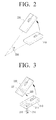
FIGS. 2 and 3 illustrate the remote controller apparatus in which the operating mode is changed according to an exemplary embodiment. -
FIG. 2 illustrates theremote controller apparatus 100 provided with a wheel button, for use as both a mouse device and a pointing device. As illustrated, theremote controller apparatus 100 may be in astate 210 in which theremote controller apparatus 100 is placed on a flat surface and astate 220 in which theremote controller apparatus 100 is held up in the air and tilted. - Herein, the
remote controller apparatus 100 may operate as a mouse device in thestate 210 in which the apparatus is placed on a flat surface, and as a pointing device in thestate 220 in which the apparatus is held up in the air and tilted. - Further, the tilting degree may be 0 degrees with reference to the flat surface in the
state 210 in which theremote controller apparatus 100 is placed on the flat surface, and θdegrees 230 with reference to the flat surface in thestate 220 in which theremote controller apparatus 100 is held up in the air and tilted. - Therefore, the
controller 130 may determine that a preset event has occurred, when a change in the tilting degree of theremote controller apparatus 100 is sensed through a gyro sensor or a tilt sensor provided on or in theremote controller apparatus 100, and change the operating mode based on the change in the tilting degree. - Specifically, the
controller 130 may change the operating mode to a mouse device mode or a pointing device mode based on the change in the tilting degree. However, the changeable operating modes may not be limited to the above examples only. Accordingly, the operating modes may be changed to various modes according to various user settings. - Referring to
FIG. 3 , in thestate 210 in which theremote controller apparatus 100 is placed on the flat surface,infrared light 212 emitted from theremote controller apparatus 100 may arrive at the surface and be reflected, and reflectedinfrared light 213 may be received at aninfrared sensor 211 provided on the remote controller apparatus. Theinfrared sensor 211 may, in one or more embodiments, also emit theinfrared radiation 213 to the surface. Accordingly, thecontroller 130 may determine the movement of theremote controller apparatus 100 sensing the reflectedinfrared light 213 being received. - In the
state 220 in which theremote controller apparatus 100 is held up in the air and tilted, theinfrared light 222 emitted from theinfrared sensor 221 provided on theremote controller apparatus 100 may not arrive at the surface. Further, even when the infrared light arrives at the surface, the reflected infrared light 223 may not be sensed by theinfrared sensor 221, for example, because of a weak intensity. - Therefore, when the infrared light emitted from the infrared sensor provided on the
remote controller apparatus 100 is received at the infrared sensor, thecontroller 130 may determine that theremote controller apparatus 100 is in thestate 210 of being placed on the flat surface, and, thus, operate in the mouse operating mode. Further, when the infrared light emitted from the infrared sensor provided on theremote controller apparatus 100 is not sensed by the infrared sensor, thecontroller 130 may determine that theremote controller apparatus 100 is in thestate 220 of being held up in the air and tilted, and thus operate in the pointing device mode. - Further, the
controller 130 may control the movement status of the pointing object by calculating position information corresponding to the movement of theremote controller apparatus 100 with one of a plurality of different methods, while changing the operating mode of theremote controller apparatus 100 in response to a preset event including, for example, the tilting degree of theremote controller apparatus 100 being changed, and the infrared light emitted from the infrared sensor provided on the remote controller apparatus not being received at the infrared sensor. In other words, the position information is calculated using a different method in dependence on the operating mode of theremote controller apparatus 100. - When the operating mode is changed, the
controller 130 may calculate the position information corresponding to the movement of the remote controller apparatus with either an absolute coordinate method or a relative coordinate method. The absolute coordinate method calculates coordinates corresponding to a position of the pointing object based on the coordinates mapped on the screen provided on an external device, and the relative coordinate method calculates an amount of the motion of the pointing object based on a current position of the pointing object. - The absolute coordinate method may be based on coordinates mapped to a screen provided on the external device. The relative coordinate method may be based on a relative coordinate system based on an amount of the motion of the remote control and a current position of a pointing object displayed on the screen.
- Referring to
FIGS. 4 and5 , the absolute coordinate method and the relative coordinate method will be described in greater detail below. -
FIG. 4 is a view provided to explain the absolute coordinate method according to an exemplary embodiment. - Referring to
FIG. 4 , the external device 400 (i.e., display apparatus 400) displaying apointing object 420 thereon is illustrated. Adisplay 410 provided on thedisplay apparatus 400 may display thepointing object 420. - Herein, the coordinates may be mapped respectively based on vertices A, B, C, D (41, 412, 413, 414) of the
display 410. - For example, when it is assumed that the vertex A (411) is mapped with (0, 0), that the vertex B (412) is mapped with (0, 1000), that the vertex C (413) is mapped with (1000, 1000), and that the vertex D (414) is mapped with (1000, 0), the coordinates from (0, 0) to (1000, 000) may be mapped on the
display 410 including the vertices A, B, C, D (411, 412, 413, 414). - Further, coordinates corresponding to the position of the
pointing object 420 displayed currently on thedisplay 410 may be indicated correctly with numbers. For example, the coordinate corresponding to the position of thepointing object 420 may be specified with one coordinate set such as (20, 20) among a plurality of coordinates mapped on thedisplay 410. - Further, while the
remote controller apparatus 100 controls movement status of thepointing object 420, in response to inputting the coordinate values (200, 200) according to an operation of a user, theremote controller apparatus 100 may control thepointing object 420 to be moved toward a point corresponding to the coordinates (200, 200) among the coordinates from (0, 0) to (1000, 000) mapped on thedisplay 410. - As explained above with reference to
FIG. 4 , the absolute coordinate method calculates coordinates corresponding to the position of the pointing object based on the coordinates mapped on the screen provided on the external apparatus. -
FIG. 5 is a view provided to explain the relative coordinate method according to an exemplary embodiment. - Referring to
FIG. 5 , an external device 500 (i.e., display apparatus 500) displaying apointing object 520 thereon and aremote controller apparatus 530 are illustrated. Further, adisplay 510 provided on thedisplay apparatus 500 may display thepointing object 520. - Rather than controlling the movement of the
pointing object 520 by using the coordinates mapped on the display 510 (seeFIG. 4 ), theremote controller apparatus 530 ofFIG. 5 may control the movement of thepointing object 520 by calculating an amount of motion of thepointing object 520 based on a current position of thepointing object 520. - For example, the
remote controller apparatus 530 may control the movement of thepointing object 520 based on a current position of thepointing object 520 displayed on thedisplay 510. As illustrated inFIG. 5 , when theremote controller apparatus 530 moves toward the right direction as much as "a" and toward the upper direction as much as "b", the amount of the motion of theremote controller apparatus 530 may be (a, b). Thus, according to the amount of the motion of theremote controller apparatus 530, thepointing object 520 may be moved toward the right direction as much as "a" and toward the upper direction as much as "b". - One difference between the absolute coordinate method of
FIG. 4 and the relative coordinate method ofFIG. 5 will be described below. When the numbers (100, 100) are input to the remote controller apparatus using the absolute coordinate method, the remote controller apparatus using the absolute coordinate method may move the pointing object to be placed on coordinate corresponding to (100, 100) among the coordinates mapped on the display. - When the numbers (100, 100) are input to the remote controller apparatus using the relative coordinate method, the remote controller apparatus using the relative coordinate method may move the pointing object as much as (100, 100) toward a specific direction away from a current position of the pointing object. For example, when the numbers input to the remote controller apparatus using the relative coordinate method are 100 toward the right direction and 100 toward the upper direction, the remote controller apparatus using the relative coordinate method may move the pointing object as much as (100, 100) toward the right direction and the upper direction from a current position of the pointing object.
- The
controller 130 may change the operating mode of the remote controller apparatus in response to a preset event. When the changed operating mode is a pointing device mode, position information corresponding to the movement of theremote controller apparatus 100 may be calculated through the absolute coordinate method as described inFIG. 4 and movement status of the pointing object may be controlled so that the pointing object is moved toward one of the mapped coordinates on the screen. - Thus, when the
remote controller apparatus 100 operates in the pointing device mode, the pointing object displayed on the screen may be positioned on the direction pointed by theremote controller apparatus 100. Thecontroller 130 may calculate position information corresponding to the movement of theremote controller apparatus 100 with the absolute coordinate method, and move the pointing object toward one of the mapped coordinates on the screen. - Further, when the
controller 130 changes the operating mode of the remote controller apparatus in response to a preset event to a mouse device mode, thecontroller 130 may calculate position information corresponding to the movement of theremote controller apparatus 100 through the relative coordinate method as described inFIG. 5 , and control the movement status of the pointing object according to an amount of the motion of the remote controller apparatus corresponding to the calculated position information. - Thus, as illustrated in
FIG. 5 , when theremote controller apparatus 530 operates in the mouse device mode, the pointing object displayed on the screen may be moved on the screen in response to the movement direction and amount of the motion of theremote controller apparatus 530 based on a current position of the pointing object. - When the pointing object is moved toward the coordinates other than, or outside of the mapped coordinates on the screen, the
controller 130 may generate a control signal to perform a preset function and transmit the control signal to the external device. -
FIG. 6 illustrates an example in which a margin area of the screen is pointed to according to an exemplary embodiment. - Referring to
FIG. 6 , theremote controller apparatus 630 may operate in one of the pointing device mode and the mouse device mode, and control the movement of thepointing object 620 displayed on thedisplay 610 of thedisplay apparatus 600. - When the
remote controller apparatus 630 moves thepointing object 620 out of an area within the margin of thedisplay 610, referred to as a mapped co-ordinate area, towards the margin at the right hand side of the display, thecontroller 130 may generate a control signal to perform a preset function and transmit the control signal to thedisplay apparatus 600. - Specifically, when the
pointing object 620 is moved toward coordinates outside the mapped coordinate area on thedisplay 610, thedisplay apparatus 600 may transmit the information indicating that thepointing object 620 is out of the mapped coordinate area on thedisplay 610 to theremote controller apparatus 630, and upon receiving such information at theremote controller apparatus 630, thecontroller 130 may generate a control signal to perform a preset function in thedisplay apparatus 600 and transmit the control signal to thedisplay apparatus 600. - For example, the preset function may include a return-to-previous screen, next screen playback, slideshow, screen turn off, or other various functions that may be excused according to user setting.
- Accordingly, a user may control the movement of the
pointing object 620 displayed on thedisplay apparatus 600 by using theremote controller apparatus 630, and may perform the other functions such as previous screen return or slideshow. -
FIG. 7 illustrates a configuration of a remote controller apparatus according to another exemplary embodiment. - Referring to
FIG. 7 , theremote controller apparatus 100 includes acommunicator 110, asensor 120, acontroller 130, and awheel button 140. Thecommunicator 110 and thesensor 120 may be similar to those described above. - The
wheel button 140 may be used in changing the visual effects of the pointing object. Thus, thecontroller 130 may generate a control signal to change the visual effects of the pointing object based on an amount of rotation of thewheel button 140 caused by an operation of a user, and transmit the control signal to the external device. -
FIG. 8 illustrates the pointing object with changed visual effects according to an exemplary embodiment. - Referring to
FIG. 8 , when thewheel button 140 provided on theremote controller apparatus 840 rotates, the control signal generated in response may be transmitted to thedisplay apparatus 800. Accordingly, the visual effects may be changed according to an amount of rotation of thewheel button 140 regarding thepointing object 820 displayed on thedisplay 810 provided on thedisplay apparatus 800. InFIG. 8 , a size of thepointing object 820 may be changed according to an amount of rotation of thewheel button 140, so that abigger pointing object 830 is displayed. - Although
FIG. 8 only illustrates that the size of thepointing object 820 may be changed according to an amount of rotation of thewheel button 140, other exemplary embodiments are possible. For example, a transparency of thepointing object 820 may be adjusted, or a color of thepointing object 820 may be adjusted. Additionally, a depth of thepointing object 820 may be adjusted. Accordingly, various visual effects may be changed in response to the rotation of thewheel button 140. - Further, in generating a control signal to change the visual effects of the
pointing object 820 based on an amount of rotation of thewheel button 140, thecontroller 130 may slightly increase the size of thepointing object 820 when an amount of rotation of thewheel button 140 is small, while further increasing the size of thepointing object 820 when an amount of rotation of thewheel button 140 is large. Further, thecontroller 130 may generate a control signal to reduce the size of thepointing object 820 when thewheel button 140 is rotated to the opposite direction from that which causes thepointing object 820 size to be increased. The above process may be uniformly applied to the process of adjusting transparency, color, or depth of thepointing object 820. -
FIG. 9 illustrates a configuration of a remote controller apparatus according to another exemplary embodiment. - Referring to
FIG. 9 , theremote controller apparatus 100 includes acommunicator 110, asensor 120, acontroller 130 and aball sensor 150. Thecommunicator 110 and thesensor 120 may be similar to those described above. - The
ball sensor 150 may extract movement tracks regarding the ball based on a rotating direction and an amount of rotation of the ball. - Further, the
controller 130 may transmit information regarding messages generated according to the extracted movement tracks regarding the ball to the external device so that the external device displays the messages. - Specifically, when a user holds the
remote controller apparatus 100 and operates the same as if writing with a pen, theball sensor 150 provided on theremote controller apparatus 100 may extract the movement tracks of the ball based on rotating direction and amount of the rotation of the ball which is moved on the surface. - Further, the
controller 130 may obtain the information regarding messages, and transmit the obtained information to the external device so that the external device displays the messages. - This operating mode of the
remote controller apparatus 100 may be defined to be the 'writing mode', in which when a user holds theremote controller apparatus 100 like a pen and when the ball of theball sensor 150 is touched on the surface, thecontroller 130 may change the operating mode into the writing mode and perform the above described operation. -
FIG. 10 illustrates a configuration of a remote controller apparatus according to yet another exemplary embodiment. - Referring to
FIG. 10 , theremote controller apparatus 100 includes acommunicator 110, asensor 120, acontroller 130 and adisplay 160. Thecommunicator 110 and thesensor 120 may be similar to those described above. - The
display 160 may display a setting screen such as a user interface screen. - Further, the
controller 130 may control thedisplay 160 to display the user interface screen. Whether or not to automatically change the operating mode of theremote controller apparatus 100 in response to a preset event may be selected through the user interface screen. - Therefore, when a user establishes that the operating mode of the
remote controller apparatus 100 is to automatically change, on the user interface screen, thecontroller 130 may automatically change the operating mode of theremote controller apparatus 100 in response to a preset event such as a change in the tilting degree of theremote controller apparatus 100 or a change in whether infrared light emitted from the infrared sensor is sensed by the infrared sensor. - However, when a user establishes that the operating mode of the
remote controller apparatus 100 is to not be changed automatically, thecontroller 130 may keep the current operating mode without changing the operating mode of theremote controller apparatus 100. - The user interface screen may be implemented as a graphical user interface (GUI) or an on screen display (OSD).
-
FIG. 11 is a flowchart provided to explain a control method of the remote controller apparatus supporting a plurality of operating modes according to an exemplary embodiment. - According to the method illustrated in
FIG. 11 , communication may be performed with an external device displaying the pointing object, at S1110. - At S1120, the movement of the remote controller apparatus may be sensed.
- At S1130, movement status of the pointing object may be controlled based on the movement of the remote controller apparatus.
- Further, at S1140, position information corresponding to the movement of the remote controller apparatus may be calculated with a different, changed method when the operating mode of the remote controller apparatus is changed in response to a preset event.
- Herein, the preset event may include at least one of the tilting degree of the remote controller apparatus being changed and a change in whether infrared light is received at the infrared sensor.
- At S1150, movement status of the pointing object may be controlled based on the calculated position information with the changed method.
- Further, when the operating mode is changed, the calculating may comprise calculation of position information corresponding to the movement of the remote controller apparatus through one of the absolute coordinate method in which coordinate corresponding to the position of the pointing object is calculated based on the mapped coordinates on the screen provided on the external device, and the relative coordinate method in which an amount of the motion of the pointing object is calculated based on a current position of the pointing object.
- Further, the calculating may comprise calculation of position information corresponding to the movement of the remote controller apparatus with the absolute coordinate method as the changed method when the operating mode is a pointing device mode. The controlling of the movement status of the pointing object based on the calculated position information with the absolute co-ordinate method may control the movement status of the pointing object so as to move the pointing object toward one of the mapped coordinates on the screen.
- Further, the calculating may comprise calculation of position information corresponding to the movement of the remote controller apparatus with the relative coordinate method as the changed method when the operating mode is a mouse device mode. The controlling movement status of the pointing object based on the calculated position information with the relative co-ordinate method may control the movement status of the pointing object according to an amount of the motion of the remote controller apparatus corresponding to the calculated position information.
- The control method of the remote controller apparatus according to an exemplary embodiment may additionally include generating a control signal to perform a preset function and transmitting the control signal to the external device when the pointing object is to be moved to coordinates other than the mapped coordinates on the screen.
- Further, the control method of the remote controller apparatus according to an exemplary embodiment may include generating a control signal to change the visual effects of the pointing object based on an amount of rotation of a wheel button which is moved according to an operation of a user and transmitting the control signal to the external device.
- Further, the control method of the remote controller apparatus according to an exemplary embodiment may include extracting the movement tracks of a ball based on a rotating direction and an amount of the rotation of the ball provided on the remote controller apparatus and transmitting the information regarding messages generated according to the extracted movement tracks of the ball to the external device so that the external device displays the messages.
- Further, the control method according to an exemplary embodiment may include displaying a user interface screen, through which whether or not to automatically change the operating mode in response to a preset event may be selected.
- A non-transitory computer readable recording medium storing programs which are executable by a computer or processor for consecutively performing the control method may be provided.
- For example, the non-transitory computer readable recording medium may store a program which implements operations of performing communication with an external device displaying the pointing object, sensing the movement of the remote controller apparatus, controlling movement status of the pointing object based on the movement of the remote controller apparatus, calculating position information corresponding to the movement of the remote controller apparatus with a different method when the operating mode of the remote controller apparatus is changed in response to a preset event, and controlling the movement status of the pointing object based on the calculated position information with the different method.
- The non-transitory computer readable recording medium may refer to a medium which stores data semi-permanently and can be read by devices, rather than a medium which stores data temporarily such as register, cache, or memory. Specifically, the above various applications or programs may be stored and provided in a non-transitory computer readable recording medium such as a compact disc (CD), a digital versatile disc (DVD), a hard disk, a Blu-ray disk, a Universal Serial Bus (USB) flash drive, a memory card, or a read only memory (ROM).
- Further, communication between respective components of the remote controller apparatus may be performed through the bus. Further, each device may include a processor such as a central processing unit (CPU) or a microprocessor for performing the various operations mentioned above.
- The foregoing exemplary embodiments and advantages are merely exemplary and are not to be construed as limiting the present invention. The present teaching can be readily applied to other types of apparatuses. Also, the description of one or more exemplary embodiments is intended to be illustrative, and not to limit the scope of the claims.
Claims (15)
- A remote controller apparatus configured to operate in a plurality of operating modes, the remote controller apparatus comprising:a communicator configured to communicate with an external device displaying a pointing object thereon;a sensor configured to sense a movement of the remote controller apparatus; anda controller configured to control movement of the pointing object based on the movement of the remote controller apparatus, determine position information corresponding to the movement of the remote controller apparatus using a first method when the remote controller apparatus operates in a first operating mode of the plurality of operating modes, determine the position information corresponding to the movement of the remote controller apparatus using a second method when the remote controller apparatus operates in a second operating mode of the plurality of operating modes, control the movement of the pointing object based on the position information, and change an operating mode of the remote controller apparatus to one of the first operating and the second operating mode in response to a preset event occurring.
- The remote controller apparatus of claim 1, wherein the preset event comprises at least one of an event in which a tilting degree of the remote controller apparatus is changed and an event in which there is a change in whether an infrared light emitted from an infrared sensor provided on the remote controller apparatus is sensed by the infrared sensor.
- The remote controller apparatus of claim 2, wherein the first method is an absolute coordinate method and the second method is a relative coordinate method,
wherein the absolute coordinate method comprises determining coordinates corresponding to the position of the pointing object based on mapped coordinates on a screen provided on the external device, and
wherein the relative coordinate method comprises determining an amount of the motion of the pointing object based on a current position of the pointing object. - The remote controller apparatus of claim 3, wherein the first operating mode is a pointing device mode, and
wherein the controller is further configured to control the movement of the pointing object so that the pointing object is moved to one of the mapped coordinates on the screen when the remote controller apparatus operates in the pointing device mode. - The remote controller apparatus of claim 3 or 4, wherein the second operating mode is a mouse device mode, and
wherein the controller is further configured to control the movement of the pointing object according to the amount of the motion of the remote controller apparatus corresponding to the position information when the remote controller apparatus operates in the mouse device mode. - The remote controller apparatus of any one of claims 3 to 5, wherein the controller is further configured to generate a control signal to perform a preset function and control the communicator to transmit the control signal to the external device when the pointing object is moved to coordinates outside the mapped coordinates on the screen.
- The remote controller apparatus of any one of claims 1 to 6, further comprising a wheel button configured to be rotatable,
wherein the controller is further configured to generate a control signal to change visual effects of the pointing object based on an amount of rotation of the wheel button, and to control the communicator to transmit the control signal to the external device. - The remote controller apparatus of any one of claims 1 to 7, further comprising a ball sensor configured to extract movement tracks of a ball based on a rotation direction and an amount of rotation of the ball,
wherein the controller is further configured to control the communicator to transmit information regarding messages generated according to the extracted movement tracks of the ball to the external device and control the external device to display the messages. - The remote controller apparatus of any one of claims 1 to 8, further comprising a display,
wherein the controller is further configured to control the display to display a user interface screen for selecting whether to automatically change the operating mode according to the preset event. - A control method of a remote controller apparatus configured to operate in a plurality of operating modes, the control method comprising:sensing a movement of the remote controller apparatus;determining position information corresponding to the movement of the remote controller apparatus;controlling a movement of a pointing object displayed on an external device based on the position information; andchanging the operating mode of the remote controller apparatus in response to a preset event occurring while the remote controller apparatus operates,wherein the determining the position information comprises:determining the position information corresponding to the movement of the remote controller apparatus using a first method when the remote controller apparatus operates in a first operating mode among the plurality of operating modes, anddetermining the position information corresponding to the movement of the remote controller apparatus using a second method when the remote controller apparatus operates in a second operating mode among the plurality of operating modes.
- The control method of claim 10, wherein the preset event comprises at least one of an event in which a tilting degree of the remote controller apparatus is changed and an event in which there is a change in whether an infrared light emitted from an infrared sensor provided on the remote controller apparatus is sensed by the infrared sensor.
- The control method of claim 11, wherein of the first method is an absolute coordinate method and the second method is a relative coordinate method,
wherein the absolute coordinate method comprises determining coordinates corresponding to the position of the pointing object based on mapped coordinates on a screen provided on the external device, and
wherein the relative coordinate method comprises determining an amount of the motion of the pointing object based on a current position of the pointing object. - The control method of claim 12, wherein the first operating mode is a pointing device mode, and
wherein the controlling comprises controlling the movement of the pointing object so that the pointing object is moved toward one of the mapped coordinates on the screen when the remote controller device operates in the pointing device mode. - The control method of claim 12 or 13, wherein the second operating mode is a mouse device mode, and
wherein the controlling comprises controlling the movement of the pointing object according to an amount of the motion of the remote controller apparatus corresponding to the position information when the remote controller device operates in the mouse device mode. - The control method of claim 13 or 14, further comprising:generating, in response to the pointing object being moved to coordinates outside the mapped coordinates on the screen, a control signal to perform a preset function; andtransmitting the control signal to the external device.
Applications Claiming Priority (1)
| Application Number | Priority Date | Filing Date | Title |
|---|---|---|---|
| KR1020140139052A KR20160044260A (en) | 2014-10-15 | 2014-10-15 | Remote contoller apparatus and controlling method thereof |
Publications (2)
| Publication Number | Publication Date |
|---|---|
| EP3010001A1 true EP3010001A1 (en) | 2016-04-20 |
| EP3010001B1 EP3010001B1 (en) | 2019-09-25 |
Family
ID=54325368
Family Applications (1)
| Application Number | Title | Priority Date | Filing Date |
|---|---|---|---|
| EP15189406.0A Not-in-force EP3010001B1 (en) | 2014-10-15 | 2015-10-12 | Remote controller apparatus and control method thereof |
Country Status (6)
| Country | Link |
|---|---|
| US (1) | US10386987B2 (en) |
| EP (1) | EP3010001B1 (en) |
| KR (1) | KR20160044260A (en) |
| CN (1) | CN105224203A (en) |
| RU (1) | RU2017107202A (en) |
| WO (1) | WO2016060458A1 (en) |
Cited By (1)
| Publication number | Priority date | Publication date | Assignee | Title |
|---|---|---|---|---|
| EP3499344A1 (en) * | 2017-12-18 | 2019-06-19 | Immersion Corporation | Haptically-enabled peripheral usable for two-dimensional and three-dimensional tracking |
Families Citing this family (7)
| Publication number | Priority date | Publication date | Assignee | Title |
|---|---|---|---|---|
| KR102248741B1 (en) * | 2015-01-29 | 2021-05-07 | 삼성전자주식회사 | Display appaeatus and control method thereof |
| KR102441328B1 (en) * | 2016-01-28 | 2022-09-08 | 삼성전자주식회사 | Method for displaying an image and an electronic device thereof |
| CN110069147B (en) * | 2018-01-23 | 2023-02-03 | 可赛尔内存股份有限公司 | Control device and control method thereof |
| EP4163772A4 (en) * | 2020-06-04 | 2024-01-31 | Lg Electronics Inc | Image display device and method for operating same |
| CN111833581B (en) * | 2020-07-14 | 2021-08-24 | 北京仁光科技有限公司 | Multi-screen laser remote control method and system |
| WO2023097573A1 (en) * | 2021-12-01 | 2023-06-08 | Huawei Technologies Co., Ltd. | Devices and methods for remote control and annotation associated with an electronic device |
| WO2023157993A1 (en) * | 2022-02-18 | 2023-08-24 | 엘지전자 주식회사 | Display device and control method thereof |
Citations (6)
| Publication number | Priority date | Publication date | Assignee | Title |
|---|---|---|---|---|
| US20070022391A1 (en) * | 2005-07-19 | 2007-01-25 | Samsung Electronics Co., Ltd. | Method and apparatus for changing a shape of a mouse cursor corresponding to an item on which the mouse cursor is located |
| US20090303184A1 (en) * | 2008-06-04 | 2009-12-10 | Wistron Corporation | Handheld electronic product and control method for automatically switching an operating mode |
| US20110169734A1 (en) * | 2010-01-12 | 2011-07-14 | Cho Sanghyun | Display device and control method thereof |
| EP2474893A1 (en) * | 2011-01-07 | 2012-07-11 | LG Electronics Inc. | Method of controlling image display device using display screen, and image display device thereof |
| US20120212678A1 (en) * | 2011-02-22 | 2012-08-23 | Chien-Fa Wang | Multimedia television remote control having a cursor control function |
| US20140196086A1 (en) * | 2013-01-09 | 2014-07-10 | Pixart Imaging Inc. | Hand-held pointing device and operation method thereof |
Family Cites Families (13)
| Publication number | Priority date | Publication date | Assignee | Title |
|---|---|---|---|---|
| RU2103723C1 (en) | 1996-01-10 | 1998-01-27 | Акционерное общество закрытого типа "Ракурс-ЗД" | Method for information input into controlled object and device which implements said method |
| JP4011987B2 (en) | 2001-09-28 | 2007-11-21 | フジノン株式会社 | Presentation system using laser pointer |
| TWI234105B (en) * | 2002-08-30 | 2005-06-11 | Ren-Guang King | Pointing device, and scanner, robot, mobile communication device and electronic dictionary using the same |
| US7910843B2 (en) | 2007-09-04 | 2011-03-22 | Apple Inc. | Compact input device |
| KR101237397B1 (en) | 2009-06-03 | 2013-02-26 | (주)레이딕스텍 | Electronic system for inputting pointing information of non-contact type and method for treating thereof |
| ES2565338T3 (en) | 2009-07-02 | 2016-04-04 | Freedom Scientific, Inc. | Increased pointer based on vectors |
| US8432305B2 (en) * | 2009-09-03 | 2013-04-30 | Samsung Electronics Co., Ltd. | Electronic apparatus, control method thereof, remote control apparatus, and control method thereof |
| KR101729527B1 (en) | 2010-09-10 | 2017-04-24 | 엘지전자 주식회사 | Apparatus for displaying image and method for operating the same |
| CN102622106A (en) * | 2011-01-28 | 2012-08-01 | 鸿富锦精密工业(深圳)有限公司 | Mouse and method for establishing Bluetooth communication between mouse and computer |
| CN102955650B (en) * | 2011-08-25 | 2016-04-20 | 幻音科技(深圳)有限公司 | Cursor slidably inputs method and device |
| CN102595224B (en) * | 2011-11-01 | 2015-09-30 | 华为技术有限公司 | A kind of remote control thereof, remote controller, remote control response method and Set Top Box |
| CN102611858A (en) * | 2012-02-24 | 2012-07-25 | 深圳创维数字技术股份有限公司 | Remote control method of multi-mode remote controller, remote controller, user terminal and system |
| DE202013100255U1 (en) * | 2012-06-20 | 2013-04-12 | Samsung Electronics Co. Ltd. | Display device, remote control device and operating function of the same |
-
2014
- 2014-10-15 KR KR1020140139052A patent/KR20160044260A/en not_active Application Discontinuation
-
2015
- 2015-10-12 EP EP15189406.0A patent/EP3010001B1/en not_active Not-in-force
- 2015-10-13 CN CN201510671181.5A patent/CN105224203A/en active Pending
- 2015-10-14 RU RU2017107202A patent/RU2017107202A/en unknown
- 2015-10-14 WO PCT/KR2015/010819 patent/WO2016060458A1/en active Application Filing
- 2015-10-15 US US14/884,212 patent/US10386987B2/en not_active Expired - Fee Related
Patent Citations (6)
| Publication number | Priority date | Publication date | Assignee | Title |
|---|---|---|---|---|
| US20070022391A1 (en) * | 2005-07-19 | 2007-01-25 | Samsung Electronics Co., Ltd. | Method and apparatus for changing a shape of a mouse cursor corresponding to an item on which the mouse cursor is located |
| US20090303184A1 (en) * | 2008-06-04 | 2009-12-10 | Wistron Corporation | Handheld electronic product and control method for automatically switching an operating mode |
| US20110169734A1 (en) * | 2010-01-12 | 2011-07-14 | Cho Sanghyun | Display device and control method thereof |
| EP2474893A1 (en) * | 2011-01-07 | 2012-07-11 | LG Electronics Inc. | Method of controlling image display device using display screen, and image display device thereof |
| US20120212678A1 (en) * | 2011-02-22 | 2012-08-23 | Chien-Fa Wang | Multimedia television remote control having a cursor control function |
| US20140196086A1 (en) * | 2013-01-09 | 2014-07-10 | Pixart Imaging Inc. | Hand-held pointing device and operation method thereof |
Cited By (1)
| Publication number | Priority date | Publication date | Assignee | Title |
|---|---|---|---|---|
| EP3499344A1 (en) * | 2017-12-18 | 2019-06-19 | Immersion Corporation | Haptically-enabled peripheral usable for two-dimensional and three-dimensional tracking |
Also Published As
| Publication number | Publication date |
|---|---|
| RU2017107202A3 (en) | 2019-05-17 |
| WO2016060458A1 (en) | 2016-04-21 |
| RU2017107202A (en) | 2018-11-15 |
| US10386987B2 (en) | 2019-08-20 |
| CN105224203A (en) | 2016-01-06 |
| KR20160044260A (en) | 2016-04-25 |
| US20160110057A1 (en) | 2016-04-21 |
| EP3010001B1 (en) | 2019-09-25 |
Similar Documents
| Publication | Publication Date | Title |
|---|---|---|
| EP3010001B1 (en) | Remote controller apparatus and control method thereof | |
| AU2013200965B2 (en) | Method and apparatus for scrolling a screen in a display apparatus | |
| US9223422B2 (en) | Remote controller and display apparatus, control method thereof | |
| KR101999119B1 (en) | Method using pen input device and terminal thereof | |
| EP3026649B1 (en) | Pointing apparaus, interface apparatus and display apparatus | |
| KR102049475B1 (en) | Input device, display device and methods of controlling thereof | |
| US20160364016A1 (en) | Display apparatus, pointing apparatus, pointing system and control methods thereof | |
| EP2998838B1 (en) | Display apparatus and method for controlling the same | |
| KR20130092074A (en) | Method and apparatus for controlling of electronic device using a control device | |
| KR20140055173A (en) | Input apparatus and input controlling method thereof | |
| US10209790B2 (en) | Remote control apparatus and control method therefor | |
| KR20150011885A (en) | User Interface Providing Method for Device and Device Thereof | |
| US20190064947A1 (en) | Display control device, pointer display method, and non-temporary recording medium | |
| CN110100224B (en) | Display device and control method thereof | |
| US10719147B2 (en) | Display apparatus and control method thereof | |
| US10963073B2 (en) | Display control device including pointer control circuitry, pointer display method, and non-temporary recording medium thereof | |
| KR20190046331A (en) | Remote control and display apparatus, control method thereof | |
| KR102125100B1 (en) | Method for controlling wearable device and apparatus thereof | |
| KR101642279B1 (en) | Touch screen equipment using projected radio frequency signal | |
| KR20150129370A (en) | Apparatus for control object in cad application and computer recordable medium storing program performing the method thereof |
Legal Events
| Date | Code | Title | Description |
|---|---|---|---|
| PUAI | Public reference made under article 153(3) epc to a published international application that has entered the european phase |
Free format text: ORIGINAL CODE: 0009012 |
|
| AK | Designated contracting states |
Kind code of ref document: A1 Designated state(s): AL AT BE BG CH CY CZ DE DK EE ES FI FR GB GR HR HU IE IS IT LI LT LU LV MC MK MT NL NO PL PT RO RS SE SI SK SM TR |
|
| AX | Request for extension of the european patent |
Extension state: BA ME |
|
| 17P | Request for examination filed |
Effective date: 20160711 |
|
| RBV | Designated contracting states (corrected) |
Designated state(s): AL AT BE BG CH CY CZ DE DK EE ES FI FR GB GR HR HU IE IS IT LI LT LU LV MC MK MT NL NO PL PT RO RS SE SI SK SM TR |
|
| STAA | Information on the status of an ep patent application or granted ep patent |
Free format text: STATUS: EXAMINATION IS IN PROGRESS |
|
| 17Q | First examination report despatched |
Effective date: 20180216 |
|
| GRAP | Despatch of communication of intention to grant a patent |
Free format text: ORIGINAL CODE: EPIDOSNIGR1 |
|
| STAA | Information on the status of an ep patent application or granted ep patent |
Free format text: STATUS: GRANT OF PATENT IS INTENDED |
|
| INTG | Intention to grant announced |
Effective date: 20190528 |
|
| GRAS | Grant fee paid |
Free format text: ORIGINAL CODE: EPIDOSNIGR3 |
|
| GRAA | (expected) grant |
Free format text: ORIGINAL CODE: 0009210 |
|
| STAA | Information on the status of an ep patent application or granted ep patent |
Free format text: STATUS: THE PATENT HAS BEEN GRANTED |
|
| AK | Designated contracting states |
Kind code of ref document: B1 Designated state(s): AL AT BE BG CH CY CZ DE DK EE ES FI FR GB GR HR HU IE IS IT LI LT LU LV MC MK MT NL NO PL PT RO RS SE SI SK SM TR |
|
| REG | Reference to a national code |
Ref country code: GB Ref legal event code: FG4D |
|
| REG | Reference to a national code |
Ref country code: CH Ref legal event code: EP |
|
| REG | Reference to a national code |
Ref country code: DE Ref legal event code: R096 Ref document number: 602015038579 Country of ref document: DE |
|
| REG | Reference to a national code |
Ref country code: AT Ref legal event code: REF Ref document number: 1184596 Country of ref document: AT Kind code of ref document: T Effective date: 20191015 |
|
| REG | Reference to a national code |
Ref country code: IE Ref legal event code: FG4D |
|
| REG | Reference to a national code |
Ref country code: NL Ref legal event code: FP |
|
| PG25 | Lapsed in a contracting state [announced via postgrant information from national office to epo] |
Ref country code: BG Free format text: LAPSE BECAUSE OF FAILURE TO SUBMIT A TRANSLATION OF THE DESCRIPTION OR TO PAY THE FEE WITHIN THE PRESCRIBED TIME-LIMIT Effective date: 20191225 Ref country code: NO Free format text: LAPSE BECAUSE OF FAILURE TO SUBMIT A TRANSLATION OF THE DESCRIPTION OR TO PAY THE FEE WITHIN THE PRESCRIBED TIME-LIMIT Effective date: 20191225 Ref country code: SE Free format text: LAPSE BECAUSE OF FAILURE TO SUBMIT A TRANSLATION OF THE DESCRIPTION OR TO PAY THE FEE WITHIN THE PRESCRIBED TIME-LIMIT Effective date: 20190925 Ref country code: HR Free format text: LAPSE BECAUSE OF FAILURE TO SUBMIT A TRANSLATION OF THE DESCRIPTION OR TO PAY THE FEE WITHIN THE PRESCRIBED TIME-LIMIT Effective date: 20190925 Ref country code: LT Free format text: LAPSE BECAUSE OF FAILURE TO SUBMIT A TRANSLATION OF THE DESCRIPTION OR TO PAY THE FEE WITHIN THE PRESCRIBED TIME-LIMIT Effective date: 20190925 Ref country code: FI Free format text: LAPSE BECAUSE OF FAILURE TO SUBMIT A TRANSLATION OF THE DESCRIPTION OR TO PAY THE FEE WITHIN THE PRESCRIBED TIME-LIMIT Effective date: 20190925 |
|
| REG | Reference to a national code |
Ref country code: LT Ref legal event code: MG4D |
|
| PG25 | Lapsed in a contracting state [announced via postgrant information from national office to epo] |
Ref country code: GR Free format text: LAPSE BECAUSE OF FAILURE TO SUBMIT A TRANSLATION OF THE DESCRIPTION OR TO PAY THE FEE WITHIN THE PRESCRIBED TIME-LIMIT Effective date: 20191226 Ref country code: RS Free format text: LAPSE BECAUSE OF FAILURE TO SUBMIT A TRANSLATION OF THE DESCRIPTION OR TO PAY THE FEE WITHIN THE PRESCRIBED TIME-LIMIT Effective date: 20190925 Ref country code: LV Free format text: LAPSE BECAUSE OF FAILURE TO SUBMIT A TRANSLATION OF THE DESCRIPTION OR TO PAY THE FEE WITHIN THE PRESCRIBED TIME-LIMIT Effective date: 20190925 |
|
| REG | Reference to a national code |
Ref country code: AT Ref legal event code: MK05 Ref document number: 1184596 Country of ref document: AT Kind code of ref document: T Effective date: 20190925 |
|
| PG25 | Lapsed in a contracting state [announced via postgrant information from national office to epo] |
Ref country code: AL Free format text: LAPSE BECAUSE OF FAILURE TO SUBMIT A TRANSLATION OF THE DESCRIPTION OR TO PAY THE FEE WITHIN THE PRESCRIBED TIME-LIMIT Effective date: 20190925 Ref country code: PT Free format text: LAPSE BECAUSE OF FAILURE TO SUBMIT A TRANSLATION OF THE DESCRIPTION OR TO PAY THE FEE WITHIN THE PRESCRIBED TIME-LIMIT Effective date: 20200127 Ref country code: ES Free format text: LAPSE BECAUSE OF FAILURE TO SUBMIT A TRANSLATION OF THE DESCRIPTION OR TO PAY THE FEE WITHIN THE PRESCRIBED TIME-LIMIT Effective date: 20190925 Ref country code: IT Free format text: LAPSE BECAUSE OF FAILURE TO SUBMIT A TRANSLATION OF THE DESCRIPTION OR TO PAY THE FEE WITHIN THE PRESCRIBED TIME-LIMIT Effective date: 20190925 Ref country code: RO Free format text: LAPSE BECAUSE OF FAILURE TO SUBMIT A TRANSLATION OF THE DESCRIPTION OR TO PAY THE FEE WITHIN THE PRESCRIBED TIME-LIMIT Effective date: 20190925 Ref country code: AT Free format text: LAPSE BECAUSE OF FAILURE TO SUBMIT A TRANSLATION OF THE DESCRIPTION OR TO PAY THE FEE WITHIN THE PRESCRIBED TIME-LIMIT Effective date: 20190925 Ref country code: EE Free format text: LAPSE BECAUSE OF FAILURE TO SUBMIT A TRANSLATION OF THE DESCRIPTION OR TO PAY THE FEE WITHIN THE PRESCRIBED TIME-LIMIT Effective date: 20190925 Ref country code: PL Free format text: LAPSE BECAUSE OF FAILURE TO SUBMIT A TRANSLATION OF THE DESCRIPTION OR TO PAY THE FEE WITHIN THE PRESCRIBED TIME-LIMIT Effective date: 20190925 |
|
| PG25 | Lapsed in a contracting state [announced via postgrant information from national office to epo] |
Ref country code: IS Free format text: LAPSE BECAUSE OF FAILURE TO SUBMIT A TRANSLATION OF THE DESCRIPTION OR TO PAY THE FEE WITHIN THE PRESCRIBED TIME-LIMIT Effective date: 20200224 Ref country code: SK Free format text: LAPSE BECAUSE OF FAILURE TO SUBMIT A TRANSLATION OF THE DESCRIPTION OR TO PAY THE FEE WITHIN THE PRESCRIBED TIME-LIMIT Effective date: 20190925 Ref country code: SM Free format text: LAPSE BECAUSE OF FAILURE TO SUBMIT A TRANSLATION OF THE DESCRIPTION OR TO PAY THE FEE WITHIN THE PRESCRIBED TIME-LIMIT Effective date: 20190925 Ref country code: CZ Free format text: LAPSE BECAUSE OF FAILURE TO SUBMIT A TRANSLATION OF THE DESCRIPTION OR TO PAY THE FEE WITHIN THE PRESCRIBED TIME-LIMIT Effective date: 20190925 |
|
| REG | Reference to a national code |
Ref country code: CH Ref legal event code: PL |
|
| REG | Reference to a national code |
Ref country code: DE Ref legal event code: R097 Ref document number: 602015038579 Country of ref document: DE |
|
| PG2D | Information on lapse in contracting state deleted |
Ref country code: IS |
|
| PG25 | Lapsed in a contracting state [announced via postgrant information from national office to epo] |
Ref country code: LU Free format text: LAPSE BECAUSE OF NON-PAYMENT OF DUE FEES Effective date: 20191012 Ref country code: LI Free format text: LAPSE BECAUSE OF NON-PAYMENT OF DUE FEES Effective date: 20191031 Ref country code: DK Free format text: LAPSE BECAUSE OF FAILURE TO SUBMIT A TRANSLATION OF THE DESCRIPTION OR TO PAY THE FEE WITHIN THE PRESCRIBED TIME-LIMIT Effective date: 20190925 Ref country code: CH Free format text: LAPSE BECAUSE OF NON-PAYMENT OF DUE FEES Effective date: 20191031 Ref country code: IS Free format text: LAPSE BECAUSE OF FAILURE TO SUBMIT A TRANSLATION OF THE DESCRIPTION OR TO PAY THE FEE WITHIN THE PRESCRIBED TIME-LIMIT Effective date: 20200126 |
|
| PLBE | No opposition filed within time limit |
Free format text: ORIGINAL CODE: 0009261 |
|
| STAA | Information on the status of an ep patent application or granted ep patent |
Free format text: STATUS: NO OPPOSITION FILED WITHIN TIME LIMIT |
|
| REG | Reference to a national code |
Ref country code: BE Ref legal event code: MM Effective date: 20191031 |
|
| PG25 | Lapsed in a contracting state [announced via postgrant information from national office to epo] |
Ref country code: MC Free format text: LAPSE BECAUSE OF FAILURE TO SUBMIT A TRANSLATION OF THE DESCRIPTION OR TO PAY THE FEE WITHIN THE PRESCRIBED TIME-LIMIT Effective date: 20190925 Ref country code: BE Free format text: LAPSE BECAUSE OF NON-PAYMENT OF DUE FEES Effective date: 20191031 |
|
| 26N | No opposition filed |
Effective date: 20200626 |
|
| GBPC | Gb: european patent ceased through non-payment of renewal fee |
Effective date: 20191225 |
|
| PG25 | Lapsed in a contracting state [announced via postgrant information from national office to epo] |
Ref country code: FR Free format text: LAPSE BECAUSE OF NON-PAYMENT OF DUE FEES Effective date: 20191125 Ref country code: IE Free format text: LAPSE BECAUSE OF NON-PAYMENT OF DUE FEES Effective date: 20191012 Ref country code: GB Free format text: LAPSE BECAUSE OF NON-PAYMENT OF DUE FEES Effective date: 20191225 |
|
| PGFP | Annual fee paid to national office [announced via postgrant information from national office to epo] |
Ref country code: NL Payment date: 20200928 Year of fee payment: 6 |
|
| PG25 | Lapsed in a contracting state [announced via postgrant information from national office to epo] |
Ref country code: SI Free format text: LAPSE BECAUSE OF FAILURE TO SUBMIT A TRANSLATION OF THE DESCRIPTION OR TO PAY THE FEE WITHIN THE PRESCRIBED TIME-LIMIT Effective date: 20190925 |
|
| PGFP | Annual fee paid to national office [announced via postgrant information from national office to epo] |
Ref country code: DE Payment date: 20200921 Year of fee payment: 6 |
|
| PG25 | Lapsed in a contracting state [announced via postgrant information from national office to epo] |
Ref country code: CY Free format text: LAPSE BECAUSE OF FAILURE TO SUBMIT A TRANSLATION OF THE DESCRIPTION OR TO PAY THE FEE WITHIN THE PRESCRIBED TIME-LIMIT Effective date: 20190925 |
|
| PG25 | Lapsed in a contracting state [announced via postgrant information from national office to epo] |
Ref country code: MT Free format text: LAPSE BECAUSE OF FAILURE TO SUBMIT A TRANSLATION OF THE DESCRIPTION OR TO PAY THE FEE WITHIN THE PRESCRIBED TIME-LIMIT Effective date: 20190925 Ref country code: HU Free format text: LAPSE BECAUSE OF FAILURE TO SUBMIT A TRANSLATION OF THE DESCRIPTION OR TO PAY THE FEE WITHIN THE PRESCRIBED TIME-LIMIT; INVALID AB INITIO Effective date: 20151012 |
|
| REG | Reference to a national code |
Ref country code: DE Ref legal event code: R119 Ref document number: 602015038579 Country of ref document: DE |
|
| PG25 | Lapsed in a contracting state [announced via postgrant information from national office to epo] |
Ref country code: TR Free format text: LAPSE BECAUSE OF FAILURE TO SUBMIT A TRANSLATION OF THE DESCRIPTION OR TO PAY THE FEE WITHIN THE PRESCRIBED TIME-LIMIT Effective date: 20190925 |
|
| REG | Reference to a national code |
Ref country code: NL Ref legal event code: MM Effective date: 20211101 |
|
| PG25 | Lapsed in a contracting state [announced via postgrant information from national office to epo] |
Ref country code: MK Free format text: LAPSE BECAUSE OF FAILURE TO SUBMIT A TRANSLATION OF THE DESCRIPTION OR TO PAY THE FEE WITHIN THE PRESCRIBED TIME-LIMIT Effective date: 20190925 |
|
| PG25 | Lapsed in a contracting state [announced via postgrant information from national office to epo] |
Ref country code: NL Free format text: LAPSE BECAUSE OF NON-PAYMENT OF DUE FEES Effective date: 20211101 Ref country code: DE Free format text: LAPSE BECAUSE OF NON-PAYMENT OF DUE FEES Effective date: 20220503 |