EP3006867B1 - Low-temperature storage device with rotating lock chamber - Google Patents
Low-temperature storage device with rotating lock chamber Download PDFInfo
- Publication number
- EP3006867B1 EP3006867B1 EP15002719.1A EP15002719A EP3006867B1 EP 3006867 B1 EP3006867 B1 EP 3006867B1 EP 15002719 A EP15002719 A EP 15002719A EP 3006867 B1 EP3006867 B1 EP 3006867B1
- Authority
- EP
- European Patent Office
- Prior art keywords
- transfer
- location
- axis
- chamber
- storage
- Prior art date
- Legal status (The legal status is an assumption and is not a legal conclusion. Google has not performed a legal analysis and makes no representation as to the accuracy of the status listed.)
- Active
Links
- 239000012212 insulator Substances 0.000 claims description 7
- 238000009413 insulation Methods 0.000 description 3
- 238000006073 displacement reaction Methods 0.000 description 2
- 239000012530 fluid Substances 0.000 description 2
- 230000015572 biosynthetic process Effects 0.000 description 1
- 238000001816 cooling Methods 0.000 description 1
- 230000001419 dependent effect Effects 0.000 description 1
- 238000010586 diagram Methods 0.000 description 1
- 230000004907 flux Effects 0.000 description 1
- 238000012423 maintenance Methods 0.000 description 1
- 230000003287 optical effect Effects 0.000 description 1
- 238000007789 sealing Methods 0.000 description 1
- 239000000725 suspension Substances 0.000 description 1
- XLYOFNOQVPJJNP-UHFFFAOYSA-N water Substances O XLYOFNOQVPJJNP-UHFFFAOYSA-N 0.000 description 1
Images


Classifications
-
- F—MECHANICAL ENGINEERING; LIGHTING; HEATING; WEAPONS; BLASTING
- F25—REFRIGERATION OR COOLING; COMBINED HEATING AND REFRIGERATION SYSTEMS; HEAT PUMP SYSTEMS; MANUFACTURE OR STORAGE OF ICE; LIQUEFACTION SOLIDIFICATION OF GASES
- F25D—REFRIGERATORS; COLD ROOMS; ICE-BOXES; COOLING OR FREEZING APPARATUS NOT OTHERWISE PROVIDED FOR
- F25D13/00—Stationary devices, e.g. cold-rooms
- F25D13/06—Stationary devices, e.g. cold-rooms with conveyors carrying articles to be cooled through the cooling space
-
- B—PERFORMING OPERATIONS; TRANSPORTING
- B01—PHYSICAL OR CHEMICAL PROCESSES OR APPARATUS IN GENERAL
- B01L—CHEMICAL OR PHYSICAL LABORATORY APPARATUS FOR GENERAL USE
- B01L7/00—Heating or cooling apparatus; Heat insulating devices
- B01L7/50—Cryostats
-
- F—MECHANICAL ENGINEERING; LIGHTING; HEATING; WEAPONS; BLASTING
- F25—REFRIGERATION OR COOLING; COMBINED HEATING AND REFRIGERATION SYSTEMS; HEAT PUMP SYSTEMS; MANUFACTURE OR STORAGE OF ICE; LIQUEFACTION SOLIDIFICATION OF GASES
- F25D—REFRIGERATORS; COLD ROOMS; ICE-BOXES; COOLING OR FREEZING APPARATUS NOT OTHERWISE PROVIDED FOR
- F25D25/00—Charging, supporting, and discharging the articles to be cooled
- F25D25/04—Charging, supporting, and discharging the articles to be cooled by conveyors
-
- G—PHYSICS
- G01—MEASURING; TESTING
- G01N—INVESTIGATING OR ANALYSING MATERIALS BY DETERMINING THEIR CHEMICAL OR PHYSICAL PROPERTIES
- G01N1/00—Sampling; Preparing specimens for investigation
- G01N1/28—Preparing specimens for investigation including physical details of (bio-)chemical methods covered elsewhere, e.g. G01N33/50, C12Q
- G01N1/42—Low-temperature sample treatment, e.g. cryofixation
-
- G—PHYSICS
- G01—MEASURING; TESTING
- G01N—INVESTIGATING OR ANALYSING MATERIALS BY DETERMINING THEIR CHEMICAL OR PHYSICAL PROPERTIES
- G01N35/00—Automatic analysis not limited to methods or materials provided for in any single one of groups G01N1/00 - G01N33/00; Handling materials therefor
- G01N35/02—Automatic analysis not limited to methods or materials provided for in any single one of groups G01N1/00 - G01N33/00; Handling materials therefor using a plurality of sample containers moved by a conveyor system past one or more treatment or analysis stations
- G01N35/04—Details of the conveyor system
-
- B—PERFORMING OPERATIONS; TRANSPORTING
- B01—PHYSICAL OR CHEMICAL PROCESSES OR APPARATUS IN GENERAL
- B01L—CHEMICAL OR PHYSICAL LABORATORY APPARATUS FOR GENERAL USE
- B01L2200/00—Solutions for specific problems relating to chemical or physical laboratory apparatus
- B01L2200/02—Adapting objects or devices to another
- B01L2200/025—Align devices or objects to ensure defined positions relative to each other
-
- B—PERFORMING OPERATIONS; TRANSPORTING
- B01—PHYSICAL OR CHEMICAL PROCESSES OR APPARATUS IN GENERAL
- B01L—CHEMICAL OR PHYSICAL LABORATORY APPARATUS FOR GENERAL USE
- B01L2200/00—Solutions for specific problems relating to chemical or physical laboratory apparatus
- B01L2200/06—Fluid handling related problems
- B01L2200/0689—Sealing
-
- B—PERFORMING OPERATIONS; TRANSPORTING
- B01—PHYSICAL OR CHEMICAL PROCESSES OR APPARATUS IN GENERAL
- B01L—CHEMICAL OR PHYSICAL LABORATORY APPARATUS FOR GENERAL USE
- B01L2300/00—Additional constructional details
- B01L2300/08—Geometry, shape and general structure
- B01L2300/0832—Geometry, shape and general structure cylindrical, tube shaped
- B01L2300/0841—Drums
-
- G—PHYSICS
- G01—MEASURING; TESTING
- G01N—INVESTIGATING OR ANALYSING MATERIALS BY DETERMINING THEIR CHEMICAL OR PHYSICAL PROPERTIES
- G01N35/00—Automatic analysis not limited to methods or materials provided for in any single one of groups G01N1/00 - G01N33/00; Handling materials therefor
- G01N2035/00346—Heating or cooling arrangements
- G01N2035/00435—Refrigerated reagent storage
-
- G—PHYSICS
- G01—MEASURING; TESTING
- G01N—INVESTIGATING OR ANALYSING MATERIALS BY DETERMINING THEIR CHEMICAL OR PHYSICAL PROPERTIES
- G01N35/00—Automatic analysis not limited to methods or materials provided for in any single one of groups G01N1/00 - G01N33/00; Handling materials therefor
- G01N35/02—Automatic analysis not limited to methods or materials provided for in any single one of groups G01N1/00 - G01N33/00; Handling materials therefor using a plurality of sample containers moved by a conveyor system past one or more treatment or analysis stations
- G01N35/04—Details of the conveyor system
- G01N2035/0401—Sample carriers, cuvettes or reaction vessels
- G01N2035/0418—Plate elements with several rows of samples
- G01N2035/042—Plate elements with several rows of samples moved independently, e.g. by fork manipulator
-
- G—PHYSICS
- G01—MEASURING; TESTING
- G01N—INVESTIGATING OR ANALYSING MATERIALS BY DETERMINING THEIR CHEMICAL OR PHYSICAL PROPERTIES
- G01N35/00—Automatic analysis not limited to methods or materials provided for in any single one of groups G01N1/00 - G01N33/00; Handling materials therefor
- G01N35/02—Automatic analysis not limited to methods or materials provided for in any single one of groups G01N1/00 - G01N33/00; Handling materials therefor using a plurality of sample containers moved by a conveyor system past one or more treatment or analysis stations
- G01N35/04—Details of the conveyor system
- G01N2035/0401—Sample carriers, cuvettes or reaction vessels
- G01N2035/0418—Plate elements with several rows of samples
- G01N2035/0425—Stacks, magazines or elevators for plates
-
- G—PHYSICS
- G01—MEASURING; TESTING
- G01N—INVESTIGATING OR ANALYSING MATERIALS BY DETERMINING THEIR CHEMICAL OR PHYSICAL PROPERTIES
- G01N35/00—Automatic analysis not limited to methods or materials provided for in any single one of groups G01N1/00 - G01N33/00; Handling materials therefor
- G01N35/02—Automatic analysis not limited to methods or materials provided for in any single one of groups G01N1/00 - G01N33/00; Handling materials therefor using a plurality of sample containers moved by a conveyor system past one or more treatment or analysis stations
- G01N35/04—Details of the conveyor system
- G01N2035/0439—Rotary sample carriers, i.e. carousels
- G01N2035/0441—Rotary sample carriers, i.e. carousels for samples
Definitions
- the invention relates to a low-temperature storage device for storing a plurality of objects at a temperature of less than 0°C, in particular below -20°C, typically at approximately -80°C.
- Storage devices of this type require sophisticated thermal and atmospheric insulation.
- warm air with comparatively high water content should be prevented from entering the storage chamber in order to avoid ice formation within the chamber.
- the problem to be solved by the present invention is therefore to provide a storage device of this type that is efficiently accessible by means of an automatic transport device and that provides a good insulation of the storage chamber.
- the low-temperature storage device comprises the following:
- the transport device can be used to manipulate the objects. By pivoting its carriage about the second axis, it can be aligned along a desired direction where an object is to be received or deposited. By said carriage being displaceable along said second axis, it can be adjusted to a desired height where an object is to be received or deposited.
- the transport device is pivotal about as well as displaceable along the second axis.
- the device further comprises, at said transfer location, a plurality of transfer storage locations, with each transfer storage location adapted to receive one of said objects.
- the carriage of the transport device can be pivotal about and/or displaceable along said second axis to be aligned with each of said transfer storage locations.
- several transfer storage locations can be handled by the transport device.
- the device can also comprise an item picker at said transfer location.
- This item picker is equipped with an item picker location for receiving an object and a picker device for removing an individual item from a plurality of items in said object at said picker location or for adding an individual item to a plurality of items in said object at said picker location.
- the carriage of the transport device is pivotal about and/or displaceable along said second axis to be aligned with said picker location.
- the transport device can also be adapted to exchange objects with such an item picker.
- the transfer storage locations are arranged above or below said item picker in order to provide a compact arrangement of parts in the transfer location.
- the device can further comprise a transfer chamber receiving said transfer location.
- the refrigerator device is adapted and structured to cool said transfer chamber to a transfer temperature below 0°C, but above the storage temperature.
- the temperature of the transfer chamber is above the one of the storage chamber, which allows to place cold-sensitive components therein and/or allows better access for users.
- the transfer chamber can further receive a transfer device structured and adapted to transfer objects between a first and second object location.
- the carriage of the transport device is pivotal about and/or displaceable along the second axis to be aligned with said first object location and to reach an object in said first object location.
- the second object location is at an opening of a housing of the low-temperature storage device. This provides a path for moving objects between the storage chamber and the outside of the low-temperature storage device.
- the present invention is advantageously used for storing laboratory objects, in particular microplates, such as multiwell plates or sample tube holders, having the standardized SBS footprint of 127.75 x 85.48 mm.
- a “low-temperature storage device” is a storage device adapted to store objects at temperatures below 0°C, in particular below -20°C, advantageously between - 90°C and -60°C.
- An “automated” transport device is a transport device structured and adapted to be controlled and operated electronically by means of a control unit performing autonomous operations.
- Figs. 1 - 3 show a low-temperature storage device for storing laboratory objects at low temperatures. It comprises a storage chamber 1 for storing the objects at temperatures e.g. between -60 and -90°C. It further comprises a transfer chamber 2 for temporarily receiving the objects at e.g. -20°C.
- a transport device 3 in a lock chamber 4 is used for automatically moving objects between storage chamber 1 and transfer chamber 2.
- a refrigerator device 5 is provided for cooling storage chamber 1 and transfer chamber 2.
- a control unit 6 controls the various components of the storage device.
- Storage chamber 1 comprises insulating walls 10 surrounding an inner space 11 having a substantially quadratic footprint.
- Inner space 11 receives a storage carousel 12 rotatable about a vertical carousel axis 13 (the "third axis" in the context of the claims).
- Carousel 12 is arranged in suspended fashion in a frame 14. As schematically shown in Fig. 11 , a rotational bearing 15 mounted to frame 14 and located at the top or above carousel 12 receives the weight of carousel 12 (i.e. at least 90% of its weight). A substantially no-weight-carrying bearing 16 located at the bottom of the carousel is used for keeping carousel axis 13 in its vertical alignment. Suspending carousel 12 in this manner has the advantage that the weight-receiving bearing 15 is located at the warmest location of storage chamber 1.
- a carousel drive 17 is provided for rotating carousel 12 about carousel axis 13.
- Carousel drive 17 comprises a carousel motor 18 (see Figs. 2 and 11 ), which is arranged outside storage chamber 1 such that it is not exposed to extremely low temperatures.
- Carousel motor 18 drives a shaft 19, which extends into storage chamber 1 in order to rotate carousel 12.
- carousel motor 18 is located in transfer chamber 2 in order to keep the temperature gradient over shaft 19 low.
- shaft 19 extends horizontally, i.e. perpendicularly to carousel axis 13, and it drives carousel 12 for rotation about carousel axis 13 by means of an angular gear 20. This design minimizes the height of the storage device.
- Carousel 12 forms a plurality of carousel storage locations 21 ( Fig. 2 ), each for receiving one of the objects to be stored.
- the carousel storage locations 21 are formed by a plurality of storage cassettes 22 arranged side by side along the periphery of carousel 12.
- Each storage cassette 22 contains a plurality of the storage locations 21 arranged above each other.
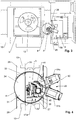
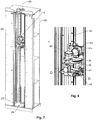
- lock chamber 4 is best seen in Figs. 4 - 7 .
- Lock chamber 4 is basically arranged in insulating wall 10 of storage chamber 1. As shown in Fig. 7 , it is rotatable about a vertical lock chamber axis 25 (the "first axis" in the context of the claims) and located within a stationary lock frame 26. A gas tight sealing is arranged between lock frame 26 and the basically cylindrical outer housing 27 of lock chamber 4 in order to prevent moisture from entering storage chamber 1.
- Opening 29 is arranged in cylindrical housing 27. Opening 29 extends from the top of lock chamber 4 to its bottom and has uniform width along its whole height in order to allow the carriage of the transport device to operate at a wide range of vertical positions, as described below.
- lock chamber 4 The interior of lock chamber 4 is divided along a plane 30 ( Fig. 4 ) into two sections 31, 32.
- plane 30 coincides with a separating wall 33. Separating plane 30 extends parallel to opening 29.
- First section 31 of lock chamber 4 receives a thermal insulator 34, while second section 32 receives transport device 3.
- Thermal insulator 34 which can e.g. be a vacuum insulator, has a maximum thickness at a location opposite opening 29. It reduces the thermal losses from lock chamber 1 through lock chamber 4.
- the maximum radial thickness ("radial" in respect to lock chamber axis 25) of thermal insulator 34 is at least 50% of the radius of cylindrical housing 27.
- Transport device 3 is, as mentioned, arranged within second section 32 of lock chamber 4. Its design can best be seen in Figs. 4 - 8 . Its purpose is to move objects between storage chamber 1 and transfer chamber 2.
- transport device 3 comprises a pivotal and vertically displaceable carriage 38.
- Carriage 38 is mounted to a carrier 39, with a pivoting motor 40 provided for pivoting carriage 38 in respect to carrier 39 about a vertical pivot axis 41 (the "second axis" in the context of the claims).
- Carrier 39 is, in its turn, mounted to a vertical guide rail 42 arranged within lock chamber 4.
- a vertical drive motor 43 is arranged on carriage 38 in order to vertically displace carriage 38 along vertical guide rail 42.
- Carriage 38 carries a manipulator 45, whose purpose is to hold the objects to be manipulated.
- manipulator 45 is formed by a shovel-like table, which can be extended below an object to be picked up and then lifted to engage the object.
- Other manipulator designs, such as grippers or clamps, are known to the skilled person.
- Manipulator 45 has a retracted and an extended position, and it can be extended, in respect to carriage 38, in horizontal direction from its retracted to its extended position in order to pick up or deposit an object. This displacement is achieved by means of a horizontal displacement motor 47.
- Pivot axis 41 extends parallel to lock chamber axis 25. However, pivot axis 41 is advantageously located closer to opening 29 than lock chamber axis 25 in order to provide space for thermal insulator 34 and also in order to have manipulator 45 closer to the locations where the objects are stored.
- lock chamber 4 When handling objects in transfer chamber 2, lock chamber 4 is rotated to a first position, as shown in Fig. 4 , where opening 29 faces the transfer location 50 in lock chamber 4.
- Carriage 38 has at least a first pivotal position 51a, which is shown in solid lines in Figs. 4 and 5 . At this first pivotal position, carriage 38 is located completely within lock chamber 4. It is brought into this first pivotal position 51a when lock chamber 4 is to be rotated.
- carriage 38 From its first pivotal position 51a, carriage 38 can be pivoted about pivot axis 41 into at least one second pivotal position (two such pivotal positions 51b, 51c are shown in Fig. 4 ), where the axis of extension of manipulator 45 aligns with a location of an object to be handled. In this second pivotal position, carriage 38 extends through opening 29, even when it is in its retracted position. In other words, pivoting carriage 38 from its first pivotal position 51a to its at least one second pivotal position 51b, 51c brings manipulator 45 closer to the location of the object to be handled.
- manipulator 45 In order to take up an object, manipulator 45 is brought into its extended position and inserted below the object, then it moved upwards by a small distance to engage the object, whereupon it can be moved by to its retracted position.
- manipulator 45 While rotating lock chamber 4 about its lock chamber axis 25, manipulator 45 is in its retracted position and pivoted into its first pivotal position 51a.
- lock chamber 4 When handling objects in storage chamber 1, lock chamber 4 is rotated to a second rotational position, as shown in Figs. 5 and 6 , where opening 29 faces storage chamber 1. In this case, carriage 38 can again be brought into its second pivotal position 51b, where manipulator 45 can be extended into one of the carousel storage locations 21.
- transfer chamber 2 holds a transfer location 50, where objects to be accessed by transport device 3 are located.
- transfer location 50 forms a plurality of locations 55a - 55d adapted to receive objects, as shown in Figs. 9 and 10 .
- Each object storage location 55a - 55d is adapted to receive one object.
- each transfer store 56 is arranged at storage location 50.
- Each transfer store 56 forms a plurality of transfer storage locations 55a above each other.
- the transfer stores 56 are arranged side by side at different angular locations in respect to pivot axis 41 of carriage 38 (when lock chamber 3 is in the position where its opening 29 faces transfer location 50 as shown in Fig. 4 ).
- each transfer store 56 can be reached by manipulator 45 by pivoting carriage 38 into two different second pivotal position 51b, 51c (cf. Fig. 4 ).
- the present device further comprises an item picker 60 at transfer location 50.
- Item picker 60 serves to remove individual items from an object or to insert an individual item into an object. This type of functionality is advantageously used when the objects are tube holders, with each object holding a plurality of sample tubes (i.e. items).
- Item picker 60 comprises an item picker location 55b for receiving one object from transport device 3. This is e.g. a holder adapted to receive a single plate in SBS format.
- Item picker 60 further comprises a picker device 62, which is adapted for removing an individual item from the plurality of items in the object at picker location 55b and/or for adding an individual item to the plurality of items in the object at picker location 55b.
- item picker 60 comprises an item store 63, which can be used to store individual items 64.
- a gripper 65 can be displaced along three mutually perpendicular axes in order to reach every item in the object at picker location 55b as well as every item in item store 63 and to move the items between these two positions.
- Item picker 60 is arranged vertically above (or below) the storage locations 55a.
- Carriage 38 of transport device 3 can be vertically displaced and pivoted for being aligned with picker location 55b or one of the storage locations 55a.
- the present device further comprises a transfer device 70 located in transfer chamber 2.
- Transfer device 70 is adapted and structured to transfer the objects between a first and second object location 71a, 71b (see Fig. 9 ).
- it comprises an object holder 72 displaceable along a horizontal guide rail 73 between the object locations 71a, 71b by means of a transfer drive 73 and a drive chain.
- First object location 71a forms one of the object locations that can be reached by the manipulator 45 of the transport device.
- Carriage 38 can be pivoted and vertically displaced for aligning manipulator 45 with first object location 71a.
- First object location 71a is located below (or above) the transfer storage locations 55a.
- Second object location 71b is located at an opening 74 of an exterior housing 80 of the present storage device (see Fig. 2 for opening 74, Fig. 1 for exterior housing 80). From second object location 71b, the object can be accessed by an external robotic system or by a user.
- Fig. 10 shows yet another component that can be arranged at transfer location 50, namely an optical scanner 76. It forms a scanner location 55d for receiving an object, which can be reached by manipulator 45.
- carriage 38 can be vertically displaced and pivoted to align manipulator 45 with scanner location 55d.
- Scanner 76 is used to scan markings on the objects and/or on items held by the objects.
- the present storage device comprises an exterior housing 80 enclosing storage chamber 1 as well as transfer chamber 2.
- a first door 81 is provided at the wall of storage chamber 1 and provides access to the interior of storage chamber 1. This door remains typically closed when the storage device is in use, but it may be opened for major service and maintenance.
- a second door 82 is provided at the wall of transfer chamber 2 and provides user access to the components within access chamber 2.
- a third door 83 which is smaller than second door 82, is also provided at the wall of transfer chamber 2 to cover opening 74, through which objects can be accessed at second object location 71b (see Fig. 9 ).
- the present storage device comprises a refrigerator device 5 for maintaining the temperatures within storage chamber 1 and transfer chamber 2.
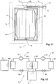
- FIG. 12 An advantageous embodiment of such a device is shown in Fig. 12 . It comprises a first heat pump 90 and a second heat pump 91.
- First heat pump 90 comprises a condenser 92, a compressor 93, an evaporator 94 and an expansion valve 95.
- Compressor 93 pumps a fluid through condenser 92, expansion valve 95 and evaporator 94 in order to transfer heat from evaporator 94 to condenser 92 in a generally known manner.
- second heat pump 91 comprises a condenser 96, a compressor 97, an evaporator 98 and an expansion valve 99.
- Compressor 97 also pumps a fluid through condenser 96, expansion valve 99 and evaporator 98 in order to transfer heat from evaporator 98 to condenser 96.
- First heat pump 90 is structured and adapted to pump heat from transfer chamber 2 to the environment.
- evaporator 94 is in thermal contact with transfer chamber 2 and condenser 92 is in thermal contact with the environment.
- Second heat pump 91 is structured and adapted to pump heat from storage chamber 1 to evaporator 94 of first heat pump 90.
- the heat pumps 90, 91 are thermally arranged in series.
- evaporator 98 of second heat pump 91 is in thermal contact with storage chamber 1
- condenser 96 of second heat pump 91 is in thermal contact with evaporator 94 of first heat pump 90
- evaporator 98 of second heat pump is in thermal contact with storage chamber 1.
- storage chamber 1 holds a single carousel and has substantially quadratic footprint.
- storage chamber 1 can e.g. be of rectangular footprint and hold two carousels side-by-side, or the carousel can be replaced with some other type of apparatus suitable for storing the objects.
- carriage 38 is pivotal as well as vertically displaceable. However, depending on its application, it could also only be pivotal or only be vertically displaceable.
- transfer location 50 is located in transfer chamber 2. This allows to maintain transfer location 50 at a temperature below 0°C and at low humidity, thereby reducing the amount of moisture passing into storage chamber 1 during operation of transport device 3.
- transfer chamber 2 can be dispensed with - in this case, transfer location 50 is located e.g. outside the outer housing of the storage device.
Description
- The invention relates to a low-temperature storage device for storing a plurality of objects at a temperature of less than 0°C, in particular below -20°C, typically at approximately -80°C.
- A device of this type is described in
US 2003/0233842 . - Storage devices of this type require sophisticated thermal and atmospheric insulation. In particular, warm air with comparatively high water content should be prevented from entering the storage chamber in order to avoid ice formation within the chamber.
- This is particularly true for storage devices adapted to store objects at temperatures below -20°C, in particular at approximately -80°C.
- On the other hand, many applications of such storage devices, in particular as used in laboratory automation, require the objects in the storage chamber to be accessible by means of an automated transport device, such as a robot.
- The prior art closest to the subject-matter of claim 1 is considered to be the document
WO98/05753 - The problem to be solved by the present invention is therefore to provide a storage device of this type that is efficiently accessible by means of an automatic transport device and that provides a good insulation of the storage chamber.
- This problem is solved by the low-temperature storage-device of claim 1.
- Accordingly, the low-temperature storage device comprises the following:
- A storage chamber for receiving the objects. This storage chamber typically contains a plurality of storage locations, e.g. formed by shelves or ledges in storage cassettes, for receiving the objects.
- A refrigerator device adapted and structured to cool the storage chamber to a storage temperature below 0°C, in particular below -20°C. The refrigerator device can e.g. comprise one or more heat pumps, and the storage temperature is advantageously between -90°C and -60°C.
- An insulating wall enclosing the storage chamber. This wall provides thermal insulation. Also, it is advantageously gas-tight in order to prevent humidity from entering the storage chamber. It can comprise one or more closeable openings.
- A transfer location arranged outside said storage chamber. This is a designated location for intermediately receiving objects that leave the storage chamber or that are to be moved into the storage chamber.
- A lock chamber arranged in said insulating wall, wherein said lock chamber comprises a cylindrical housing and an opening arranged in said cylindrical housing, and wherein said lock chamber is rotatable about a first axis for selectively orienting said opening towards said storage chamber or said transfer location. The objects can pass this lock chamber on their way between the storage chamber and the transfer location. The lock chamber prevents a free gas exchange between the storage chamber and its surroundings.
- An automatic transport device arranged in said lock chamber, wherein said transport device comprises
- a) a carriage pivotal -relatively to (i.e. in relation to) said lock chamber- about a second axis and/or displaceable -relatively to said lock chamber-along the second axis, wherein said second axis is parallel to said first axis,
- b) a manipulator arranged on said carriage and extendible from a retracted position in a direction perpendicular to said second axis into an extended position, and
- The transport device can be used to manipulate the objects. By pivoting its carriage about the second axis, it can be aligned along a desired direction where an object is to be received or deposited. By said carriage being displaceable along said second axis, it can be adjusted to a desired height where an object is to be received or deposited.
- By providing the pivotal and/or displaceable carriage in addition to having a rotatable lock chamber, it becomes possible to quickly and easily adjust the position of manipulator. Due to its higher weight and potentially higher friction, such movements could not be easily carried out by the lock chamber alone.
- Advantageously, the transport device is pivotal about as well as displaceable along the second axis.
- Advantageously, the device further comprises, at said transfer location, a plurality of transfer storage locations, with each transfer storage location adapted to receive one of said objects. In this case, the carriage of the transport device can be pivotal about and/or displaceable along said second axis to be aligned with each of said transfer storage locations. In this case, several transfer storage locations can be handled by the transport device.
- The device can also comprise an item picker at said transfer location. This item picker is equipped with
an item picker location for receiving an object and
a picker device for removing an individual item from a plurality of items in said object at said picker location or for adding an individual item to a plurality of items in said object at said picker location. - In this case, the carriage of the transport device is pivotal about and/or displaceable along said second axis to be aligned with said picker location. Hence, the transport device can also be adapted to exchange objects with such an item picker.
- Advantageously, the transfer storage locations are arranged above or below said item picker in order to provide a compact arrangement of parts in the transfer location.
- In yet another embodiment, the device can further comprise a transfer chamber receiving said transfer location. In this case, the refrigerator device is adapted and structured to cool said transfer chamber to a transfer temperature below 0°C, but above the storage temperature. By providing such a transfer chamber at a low temperature, the flux of humidity into the storage chamber can be reduced further. However, the temperature of the transfer chamber is above the one of the storage chamber, which allows to place cold-sensitive components therein and/or allows better access for users.
- The transfer chamber can further receive a transfer device structured and adapted to transfer objects between a first and second object location. The carriage of the transport device is pivotal about and/or displaceable along the second axis to be aligned with said first object location and to reach an object in said first object location. The second object location is at an opening of a housing of the low-temperature storage device. This provides a path for moving objects between the storage chamber and the outside of the low-temperature storage device.
- The present invention is advantageously used for storing laboratory objects, in particular microplates, such as multiwell plates or sample tube holders, having the standardized SBS footprint of 127.75 x 85.48 mm.
- Other advantageous embodiments are listed in the dependent claims as well as in the description below.
- The invention will be better understood and objects other than those set forth above will become apparent from the following detailed description thereof. Such description makes reference to the annexed drawings, wherein:
-
Fig. 1 shows a view of a low-temperature device, -
Fig. 2 shows the device ofFig. 1 with partially removed walls, -
Fig. 3 shows a top view of the device with the top walls removed and the storage cassettes on the carousel not shown, -
Fig. 4 shows an enlarged view of the device ofFig. 3 depicting the lock chamber and the transport device, with the lock chamber's opening being aligned with the transfer location, -
Fig. 5 shows the view ofFig. 4 with the lock chamber's opening being aligned with the storage chamber, -
Fig. 6 shows the view ofFig. 5 with the manipulator device in its extended position, -
Fig. 7 shows the lock chamber with its surrounding frame, -
Fig. 8 shows an enlarged view of the transport device ofFig. 7 , -
Fig. 9 shows a set of components arranged in the transfer location, -
Fig. 10 shows an alternative set of components arranged in the transfer location, -
Fig. 11 shows a schematic view of the suspension of the carousel and -
Fig. 12 shows a schematic diagram of the components of the refrigerator device. - A "low-temperature storage device" is a storage device adapted to store objects at temperatures below 0°C, in particular below -20°C, advantageously between - 90°C and -60°C.
- An "automated" transport device is a transport device structured and adapted to be controlled and operated electronically by means of a control unit performing autonomous operations.
-
Figs. 1 - 3 show a low-temperature storage device for storing laboratory objects at low temperatures. It comprises a storage chamber 1 for storing the objects at temperatures e.g. between -60 and -90°C. It further comprises atransfer chamber 2 for temporarily receiving the objects at e.g. -20°C.A transport device 3 in alock chamber 4 is used for automatically moving objects between storage chamber 1 and transferchamber 2. Arefrigerator device 5 is provided for cooling storage chamber 1 and transferchamber 2. A control unit 6 controls the various components of the storage device. - These components are described in more detail in the following.
- Storage chamber 1 comprises insulating
walls 10 surrounding aninner space 11 having a substantially quadratic footprint.Inner space 11 receives astorage carousel 12 rotatable about a vertical carousel axis 13 (the "third axis" in the context of the claims). -
Carousel 12 is arranged in suspended fashion in aframe 14. As schematically shown inFig. 11 , arotational bearing 15 mounted to frame 14 and located at the top or abovecarousel 12 receives the weight of carousel 12 (i.e. at least 90% of its weight). A substantially no-weight-carryingbearing 16 located at the bottom of the carousel is used for keepingcarousel axis 13 in its vertical alignment. Suspendingcarousel 12 in this manner has the advantage that the weight-receivingbearing 15 is located at the warmest location of storage chamber 1. - A
carousel drive 17 is provided for rotatingcarousel 12 aboutcarousel axis 13. Carousel drive 17 comprises a carousel motor 18 (seeFigs. 2 and11 ), which is arranged outside storage chamber 1 such that it is not exposed to extremely low temperatures.Carousel motor 18 drives ashaft 19, which extends into storage chamber 1 in order to rotatecarousel 12. - Advantageously,
carousel motor 18 is located intransfer chamber 2 in order to keep the temperature gradient overshaft 19 low. - In the embodiment shown,
shaft 19 extends horizontally, i.e. perpendicularly tocarousel axis 13, and it drivescarousel 12 for rotation aboutcarousel axis 13 by means of anangular gear 20. This design minimizes the height of the storage device. -
Carousel 12 forms a plurality of carousel storage locations 21 (Fig. 2 ), each for receiving one of the objects to be stored. As can be seen fromFig. 2 , thecarousel storage locations 21 are formed by a plurality ofstorage cassettes 22 arranged side by side along the periphery ofcarousel 12. Eachstorage cassette 22 contains a plurality of thestorage locations 21 arranged above each other. - The design of
lock chamber 4 is best seen inFigs. 4 - 7 . -
Lock chamber 4 is basically arranged in insulatingwall 10 of storage chamber 1. As shown inFig. 7 , it is rotatable about a vertical lock chamber axis 25 (the "first axis" in the context of the claims) and located within astationary lock frame 26. A gas tight sealing is arranged betweenlock frame 26 and the basically cylindricalouter housing 27 oflock chamber 4 in order to prevent moisture from entering storage chamber 1. - An
opening 29 is arranged incylindrical housing 27.Opening 29 extends from the top oflock chamber 4 to its bottom and has uniform width along its whole height in order to allow the carriage of the transport device to operate at a wide range of vertical positions, as described below. - The interior of
lock chamber 4 is divided along a plane 30 (Fig. 4 ) into twosections plane 30 coincides with a separatingwall 33. Separatingplane 30 extends parallel toopening 29.First section 31 oflock chamber 4 receives athermal insulator 34, whilesecond section 32 receivestransport device 3. -
Thermal insulator 34, which can e.g. be a vacuum insulator, has a maximum thickness at a location opposite opening 29. It reduces the thermal losses from lock chamber 1 throughlock chamber 4. Advantageously, the maximum radial thickness ("radial" in respect to lock chamber axis 25) ofthermal insulator 34 is at least 50% of the radius ofcylindrical housing 27. -
Transport device 3 is, as mentioned, arranged withinsecond section 32 oflock chamber 4. Its design can best be seen inFigs. 4 - 8 . Its purpose is to move objects between storage chamber 1 and transferchamber 2. - As can be seen from
Fig. 8 ,transport device 3 comprises a pivotal and verticallydisplaceable carriage 38.Carriage 38 is mounted to acarrier 39, with a pivotingmotor 40 provided for pivotingcarriage 38 in respect tocarrier 39 about a vertical pivot axis 41 (the "second axis" in the context of the claims).Carrier 39 is, in its turn, mounted to avertical guide rail 42 arranged withinlock chamber 4. Avertical drive motor 43 is arranged oncarriage 38 in order to vertically displacecarriage 38 alongvertical guide rail 42. -
Carriage 38 carries amanipulator 45, whose purpose is to hold the objects to be manipulated. In the shown embodiment,manipulator 45 is formed by a shovel-like table, which can be extended below an object to be picked up and then lifted to engage the object. Other manipulator designs, such as grippers or clamps, are known to the skilled person. -
Manipulator 45 has a retracted and an extended position, and it can be extended, in respect tocarriage 38, in horizontal direction from its retracted to its extended position in order to pick up or deposit an object. This displacement is achieved by means of ahorizontal displacement motor 47. -
Pivot axis 41 extends parallel to lockchamber axis 25. However,pivot axis 41 is advantageously located closer to opening 29 thanlock chamber axis 25 in order to provide space forthermal insulator 34 and also in order to havemanipulator 45 closer to the locations where the objects are stored. - When handling objects in
transfer chamber 2,lock chamber 4 is rotated to a first position, as shown inFig. 4 , where opening 29 faces thetransfer location 50 inlock chamber 4. -
Carriage 38 has at least a firstpivotal position 51a, which is shown in solid lines inFigs. 4 and5 . At this first pivotal position,carriage 38 is located completely withinlock chamber 4. It is brought into this firstpivotal position 51a whenlock chamber 4 is to be rotated. - From its first
pivotal position 51a,carriage 38 can be pivoted aboutpivot axis 41 into at least one second pivotal position (two suchpivotal positions Fig. 4 ), where the axis of extension ofmanipulator 45 aligns with a location of an object to be handled. In this second pivotal position,carriage 38 extends throughopening 29, even when it is in its retracted position. In other words, pivotingcarriage 38 from its firstpivotal position 51a to its at least one secondpivotal position manipulator 45 closer to the location of the object to be handled. - In order to take up an object,
manipulator 45 is brought into its extended position and inserted below the object, then it moved upwards by a small distance to engage the object, whereupon it can be moved by to its retracted position. - While
rotating lock chamber 4 about itslock chamber axis 25,manipulator 45 is in its retracted position and pivoted into its firstpivotal position 51a. - When handling objects in storage chamber 1,
lock chamber 4 is rotated to a second rotational position, as shown inFigs. 5 and 6 , where opening 29 faces storage chamber 1. In this case,carriage 38 can again be brought into its secondpivotal position 51b, wheremanipulator 45 can be extended into one of thecarousel storage locations 21. - As mentioned,
transfer chamber 2 holds atransfer location 50, where objects to be accessed bytransport device 3 are located. - Advantageously,
transfer location 50 forms a plurality oflocations 55a - 55d adapted to receive objects, as shown inFigs. 9 and10 . Eachobject storage location 55a - 55d is adapted to receive one object. - In the embodiments of
Fig. 9 and10 , twotransfer stores 56 are arranged atstorage location 50. Eachtransfer store 56 forms a plurality oftransfer storage locations 55a above each other. The transfer stores 56 are arranged side by side at different angular locations in respect to pivotaxis 41 of carriage 38 (whenlock chamber 3 is in the position where itsopening 29 facestransfer location 50 as shown inFig. 4 ). Hence, eachtransfer store 56 can be reached bymanipulator 45 by pivotingcarriage 38 into two different secondpivotal position Fig. 4 ). - In the embodiment of
Fig. 9 , the present device further comprises anitem picker 60 attransfer location 50.Item picker 60 serves to remove individual items from an object or to insert an individual item into an object. This type of functionality is advantageously used when the objects are tube holders, with each object holding a plurality of sample tubes (i.e. items). -
Item picker 60 comprises anitem picker location 55b for receiving one object fromtransport device 3. This is e.g. a holder adapted to receive a single plate in SBS format. -
Item picker 60 further comprises apicker device 62, which is adapted for removing an individual item from the plurality of items in the object atpicker location 55b and/or for adding an individual item to the plurality of items in the object atpicker location 55b. - In the embodiment of
Fig. 9 ,item picker 60 comprises anitem store 63, which can be used to storeindividual items 64. Agripper 65 can be displaced along three mutually perpendicular axes in order to reach every item in the object atpicker location 55b as well as every item initem store 63 and to move the items between these two positions. -
Item picker 60 is arranged vertically above (or below) thestorage locations 55a.Carriage 38 oftransport device 3 can be vertically displaced and pivoted for being aligned withpicker location 55b or one of thestorage locations 55a. - In the embodiments of
Figs. 9 and10 , the present device further comprises atransfer device 70 located intransfer chamber 2.Transfer device 70 is adapted and structured to transfer the objects between a first andsecond object location Fig. 9 ). For this purpose, it comprises anobject holder 72 displaceable along ahorizontal guide rail 73 between theobject locations transfer drive 73 and a drive chain. -
First object location 71a forms one of the object locations that can be reached by themanipulator 45 of the transport device.Carriage 38 can be pivoted and vertically displaced for aligningmanipulator 45 withfirst object location 71a.First object location 71a is located below (or above) thetransfer storage locations 55a. -
Second object location 71b is located at anopening 74 of anexterior housing 80 of the present storage device (seeFig. 2 for opening 74,Fig. 1 for exterior housing 80). Fromsecond object location 71b, the object can be accessed by an external robotic system or by a user. -
Fig. 10 shows yet another component that can be arranged attransfer location 50, namely anoptical scanner 76. It forms ascanner location 55d for receiving an object, which can be reached bymanipulator 45. For this purpose,carriage 38 can be vertically displaced and pivoted to alignmanipulator 45 withscanner location 55d. -
Scanner 76 is used to scan markings on the objects and/or on items held by the objects. - As already mentioned and as shown in
Fig. 1 , the present storage device comprises anexterior housing 80 enclosing storage chamber 1 as well astransfer chamber 2. - A
first door 81 is provided at the wall of storage chamber 1 and provides access to the interior of storage chamber 1. This door remains typically closed when the storage device is in use, but it may be opened for major service and maintenance. - A
second door 82 is provided at the wall oftransfer chamber 2 and provides user access to the components withinaccess chamber 2. - A
third door 83, which is smaller thansecond door 82, is also provided at the wall oftransfer chamber 2 to coveropening 74, through which objects can be accessed atsecond object location 71b (seeFig. 9 ). - As mentioned, the present storage device comprises a
refrigerator device 5 for maintaining the temperatures within storage chamber 1 and transferchamber 2. - An advantageous embodiment of such a device is shown in
Fig. 12 . It comprises afirst heat pump 90 and asecond heat pump 91.First heat pump 90 comprises acondenser 92, acompressor 93, anevaporator 94 and anexpansion valve 95.Compressor 93 pumps a fluid throughcondenser 92,expansion valve 95 andevaporator 94 in order to transfer heat fromevaporator 94 tocondenser 92 in a generally known manner. Similarly,second heat pump 91 comprises acondenser 96, acompressor 97, anevaporator 98 and anexpansion valve 99.Compressor 97 also pumps a fluid throughcondenser 96,expansion valve 99 andevaporator 98 in order to transfer heat fromevaporator 98 tocondenser 96. -
First heat pump 90 is structured and adapted to pump heat fromtransfer chamber 2 to the environment. For this purpose,evaporator 94 is in thermal contact withtransfer chamber 2 andcondenser 92 is in thermal contact with the environment. -
Second heat pump 91 is structured and adapted to pump heat from storage chamber 1 to evaporator 94 offirst heat pump 90. In other words, theheat pumps evaporator 98 ofsecond heat pump 91 is in thermal contact with storage chamber 1,condenser 96 ofsecond heat pump 91 is in thermal contact withevaporator 94 offirst heat pump 90, andevaporator 98 of second heat pump is in thermal contact with storage chamber 1. - This design with two heat pumps arranged "in series" and the first heat pump also being used to
cool transfer chamber 2 provides a high level of efficiency. - In the embodiment shown above, storage chamber 1 holds a single carousel and has substantially quadratic footprint. Alternatively, storage chamber 1 can e.g. be of rectangular footprint and hold two carousels side-by-side, or the carousel can be replaced with some other type of apparatus suitable for storing the objects.
- In the example above,
carriage 38 is pivotal as well as vertically displaceable. However, depending on its application, it could also only be pivotal or only be vertically displaceable. - Advantageously,
transfer location 50 is located intransfer chamber 2. This allows to maintaintransfer location 50 at a temperature below 0°C and at low humidity, thereby reducing the amount of moisture passing into storage chamber 1 during operation oftransport device 3. However, in an alternative embodiment,transfer chamber 2 can be dispensed with - in this case,transfer location 50 is located e.g. outside the outer housing of the storage device. - While there are shown and described presently preferred embodiments of the invention, it is to be distinctly understood that the invention is not limited thereto but may be otherwise variously embodied and practiced within the scope of the following claims.
Claims (19)
- A low-temperature storage device for storing a plurality of objects, comprising
a storage chamber (1) for receiving said objects,
a refrigerator device (90, 91) adapted and structured to cool said storage chamber (1) to a storage temperature below 0°C, in particular below -20°C,
an insulating wall (10) enclosing said storage chamber (1),
a transfer location (50) arranged outside said storage chamber (1),
a lock chamber (4) arranged in said insulating wall (10), wherein said lock chamber (4) comprises a cylindrical housing (27) and an opening (29) arranged in said cylindrical housing (27), and wherein said lock chamber (4) is rotatable about a first axis (25) for selectively orienting said opening (29) towards said storage chamber (1) or said transfer location (50),
an automatic transport device (3) arranged in said lock chamber (4), wherein said transport device (3) comprisesa) a carriage (38) pivotal, relatively to said lock chamber (4), about a second axis and/or displaceable, relatively to said lock chamber (4), along the second axis, wherein said second axis is parallel to said first axis (25),b) a manipulator (45) arranged on said carriage (38) and extendible from a retracted position in a direction perpendicular to said second axis into an extended position, andwherein said transport device (3) is adapted to transport objects between said storage chamber (1) and said transfer location (50) by means of said manipulator (45). - The device of claim 1 wherein said first and said second axes (25, 41) are vertical.
- The device of any of the preceding claims wherein said second axis (41) is closer to said opening (29) than said first axis (25).
- The device of any of the preceding claims wherein said transport device (3) is pivotal about said second axis (41) and displaceable along the second axis (41).
- The device of any of the preceding claims further comprising, at said transfer location (50), a plurality of transfer storage locations (55a), with each transfer storage location (55a) adapted to receive one of said objects, wherein said carriage (38) is pivotal about and/or displaceable along said second axis to be aligned with each of said transfer storage locations (55a).
- The device of claim 5 comprising at least two transfer stores (56), wherein each transfer store (56) forms a plurality of said transfer storage locations (55a) above each other, wherein said transfer stores (56) are arranged beside each other at different angular locations in respect to said second axis (41).
- The device of any of the preceding claims further comprising, at said transfer location (50), an item picker (60), which item picker (60) comprises
an item picker location (55b) for receiving an object and
a picker device (62) structured and adapted for removing an individual item from a plurality of items in said object at said picker location (55b) and/or for adding an individual item to a plurality of items in said object at said picker location (55b),
wherein said carriage (38) is pivotal about and/or displaceable along said second axis (41) to be aligned with said picker location (55b). - The device of any of the claims 5 or 6 and of claim 7, wherein said transfer storage locations (55a) are arranged above or below said item picker (60).
- The device of any of the preceding claims further comprising a transfer chamber (2) receiving said transfer location (50), wherein said refrigerator device (90, 91) is adapted and structured to cool said transfer chamber (2) to a transfer temperature below 0°C, but above said storage temperature.
- The device of claim 9 wherein said refrigerator device (90, 91) comprises a first heat pump (90) and a second heat pump (91), with said first heat pump (90) being structured and adapted to pump heat from said transfer chamber (2) to an environment and said second heat pump (91) being structured and adapted to pump heat from said storage chamber (1) to an evaporator (94) of said first heat pump (90).
- The device of any of the claims 9 or 10 further comprising, in said transfer chamber (2), a transfer device (70) structured and adapted to transfer objects between a first and second object location (71a, 71b), wherein said carriage (38) is pivotal about and/or displaceable along said second axis (41) to be aligned with said first object location (71a) and to reach an object in said first object location (71a), and wherein said second object location (71b) is located at an opening (74) of an exterior housing (80) of said low-temperature storage device.
- The device of the claims 5 and 11 wherein said transfer storage locations (55a) are arranged above or below said first object location (71a).
- The device of any of the preceding claims further comprising, at said transfer location (50), a scanner (76) structured and adapted to scan markings on said objects or on items held by said objects, wherein said scanner (76) forms a scanner location (55d), and wherein said carriage (38) is pivotal about and/or displaceable along said second axis to be aligned with said scanner location (55d).
- The device of any of the preceding claims further comprising a carousel (12) arranged in said storage chamber (1), wherein said carousel (12) is rotatable about a third axis (13) parallel to said first axis (25), and wherein said carousel (12) forms a plurality of carousel storage locations (21), each for receiving one object,
and in particular wherein said carousel (12) is suspended from a rotational bearing (15) arranged at the top or above said carousel (12). - The device of claim 14 further comprising a carousel drive (17) for rotating said carousel (12) about said third axis (13), wherein said carousel drive (17) comprises a carousel motor (18) arranged outside said storage chamber (1) and a shaft (19) driven by said carousel motor (18) and extending into said storage chamber (1),
and in particular wherein said shaft (19) extends perpendicularly to said third axis (13) and wherein said device further comprises an angular gear (20) connecting said shaft (19) to said carousel (12). - The device of the claims 9 and 15 wherein said carousel motor (18) is arranged in said transfer chamber (2).
- The device of any of the preceding claims wherein said lock chamber (4) further comprises a thermal insulator (34) arranged within said cylindrical housing (27), wherein a thickness of said thermal insulator (34) in a direction radially in respect to said second axis is at a maximum at a location opposite said opening (29), and in particular wherein said thickness at said maximum is at least 50% of a radius of said cylindrical housing (27).
- The device of any of the preceding claims wherein said opening (29) extends from a top of said lock chamber (4) to a bottom of said lock chamber (4).
- The device of any of the preceding claims wherein said carriage (38) has a first pivotal position (51a) where it is, in its retracted position, located completely within said lock chamber (4) and from where it is pivotal into at least a second pivotal position (51b, 51c), where it extends, in its retracted position, through said opening (29),
and in particular wherein said carriage (38) is pivotal into at least two second pivotal positions (51b, 51c) at different angular locations, and wherein said device further comprises at least two locations (55a) for receiving objects at said different angular locations.
Applications Claiming Priority (1)
| Application Number | Priority Date | Filing Date | Title |
|---|---|---|---|
| CH14302014 | 2014-09-22 |
Publications (2)
| Publication Number | Publication Date |
|---|---|
| EP3006867A1 EP3006867A1 (en) | 2016-04-13 |
| EP3006867B1 true EP3006867B1 (en) | 2017-08-23 |
Family
ID=54199519
Family Applications (1)
| Application Number | Title | Priority Date | Filing Date |
|---|---|---|---|
| EP15002719.1A Active EP3006867B1 (en) | 2014-09-22 | 2015-09-21 | Low-temperature storage device with rotating lock chamber |
Country Status (2)
| Country | Link |
|---|---|
| US (1) | US9709314B2 (en) |
| EP (1) | EP3006867B1 (en) |
Families Citing this family (6)
| Publication number | Priority date | Publication date | Assignee | Title |
|---|---|---|---|---|
| EP3415005B1 (en) * | 2017-06-16 | 2022-08-03 | Liconic Ag | Automatic blood bank |
| EP4034822A1 (en) * | 2019-10-30 | 2022-08-03 | Liconic AG | High-efficiency low-temperature storage device |
| DE102019134394A1 (en) | 2019-12-13 | 2021-06-17 | Hamilton Storage Gmbh | Laboratory storage cabinet with rotating body in a transfer lock |
| WO2023026282A1 (en) * | 2021-08-22 | 2023-03-02 | Crinsurance S.A.S. | Automated biological sample vitrification, storage and thawing system |
| WO2023066557A1 (en) | 2021-10-18 | 2023-04-27 | Liconic Ag | Storage device for tube racks with a carousel and a tube picker |
| CN117305090B (en) * | 2023-11-27 | 2024-02-13 | 珠海美华医疗科技有限公司 | Sample plate storage device for drug sensitivity analysis system |
Family Cites Families (39)
| Publication number | Priority date | Publication date | Assignee | Title |
|---|---|---|---|---|
| US3272579A (en) | 1964-08-24 | 1966-09-13 | Cryogenic Eng Co | Cryogenic storage vessel with station selector |
| US3782133A (en) | 1972-08-14 | 1974-01-01 | Air Liquide | Low temperature storage vessel |
| DE2254218A1 (en) | 1972-11-06 | 1974-05-16 | Schoett Joachim | REFRIGERATOR WITH REVOLVING COOLERS |
| US4250266A (en) | 1979-12-19 | 1981-02-10 | Honeywell Inc. | Automated micro-organism culture growth and detection instrument |
| US4981409A (en) | 1985-04-16 | 1991-01-01 | Canon Kabushiki Kaisha | Cartridge auto changer |
| US4907889A (en) | 1988-03-24 | 1990-03-13 | Automation Equipment Company | Video cassette library retrieval and sequencing system |
| US5224415A (en) * | 1989-12-29 | 1993-07-06 | Gas Research Institute | Frozen food storage and dispensing system |
| US5365980A (en) | 1991-05-28 | 1994-11-22 | Instant Terminalling And Ship Conversion, Inc. | Transportable liquid products container |
| US5233844A (en) | 1991-08-15 | 1993-08-10 | Cryo-Cell International, Inc. | Storage apparatus, particularly with automatic insertion and retrieval |
| US5345395A (en) | 1991-10-31 | 1994-09-06 | Baxter Diagnostics Inc. | Specimen processing and analyzing systems and methods using photometry |
| US5449229A (en) | 1994-07-07 | 1995-09-12 | Storage Technology Corporation | Tambour door customer access port |
| CH689253A5 (en) | 1995-02-06 | 1999-01-15 | Sandoz Ag | Automatically beschickbarer climate chamber. |
| US5735587A (en) | 1995-02-06 | 1998-04-07 | Liconic Ag | Climatic cabinet, turntable and use of the turntable |
| EP0853657B1 (en) | 1996-08-05 | 2007-12-26 | Thermo Electron LED GmbH | Storage device for objects, storage station, and air-conditioned cabinet |
| US5921102A (en) | 1997-03-28 | 1999-07-13 | Cryo-Cell International, Inc. | Storage apparatus particularly with automatic insertion and retrieval |
| US6059507A (en) | 1997-04-21 | 2000-05-09 | Brooks Automation, Inc. | Substrate processing apparatus with small batch load lock |
| US6068393A (en) | 1997-11-05 | 2000-05-30 | Zymark Corporation | Robotic system for processing chemical products |
| FR2777873B1 (en) | 1998-04-22 | 2000-06-16 | Groupe Ind De Realisations Et | AUTOMATIC STORAGE DEVICE FOR BIOLOGICAL OR CHEMICAL SAMPLES |
| CH690645C1 (en) | 1999-09-02 | 2002-08-30 | Liconic Ag | STORAGE SYSTEM AND STORAGE SYSTEM WITH storage container |
| DE10024581A1 (en) | 2000-05-19 | 2001-11-29 | Kendro Lab Prod Gmbh | Climate cabinet |
| AU2001285215A1 (en) * | 2000-08-23 | 2002-03-04 | University Of Virginia Patent Foundation | Automated storage and retrieval apparatus for freezers and related method thereof |
| EP1354028B1 (en) | 2001-01-26 | 2007-09-19 | Liconic Ag | Air-conditioned storage cupboard |
| US6673595B2 (en) | 2001-08-27 | 2004-01-06 | Biocrystal, Ltd | Automated cell management system for growth and manipulation of cultured cells |
| US6751977B2 (en) * | 2002-04-17 | 2004-06-22 | Carrier Commercial Refrigeration, Inc. | Automated freezer component |
| US7065759B2 (en) | 2002-06-18 | 2006-06-20 | Hewlett-Packard Development Company, L.P. | System and method for assigning basic blocks to computer control flow paths |
| US6694767B2 (en) | 2002-06-19 | 2004-02-24 | Jouan | Work enclosure having article supports that obstruct access openings |
| US7314341B2 (en) | 2003-01-10 | 2008-01-01 | Liconic Ag | Automatic storage device and climate controlled cabinet with such a device |
| DE10332799B4 (en) | 2003-07-18 | 2007-03-01 | Fraunhofer-Gesellschaft zur Förderung der angewandten Forschung e.V. | Apparatus and method for handling a sample |
| JP2005143873A (en) | 2003-11-17 | 2005-06-09 | Taiyo Nippon Sanso Corp | Freezing container |
| US20060150659A1 (en) * | 2004-12-10 | 2006-07-13 | Sidor Michael R | Vertical storage systems |
| EP1972874B1 (en) | 2007-03-20 | 2019-02-13 | Liconic Ag | Automated substance warehouse |
| EP2078961B1 (en) | 2008-01-08 | 2020-04-08 | Liconic Ag | Device for manipulating laboratory samples |
| JP4648444B2 (en) | 2008-01-18 | 2011-03-09 | 大陽日酸株式会社 | Glove box |
| US7861540B2 (en) * | 2008-01-25 | 2011-01-04 | Hamilton Storage Technologies, Inc. | Automated storage and retrieval system for storing biological or chemical samples at ultra-low temperatures |
| EP3327391B1 (en) * | 2009-01-19 | 2021-09-22 | Liconic Ag | Automated low-temperature storage for laboratory samples |
| US8759084B2 (en) * | 2010-01-22 | 2014-06-24 | Michael J. Nichols | Self-sterilizing automated incubator |
| US9255936B2 (en) * | 2010-09-10 | 2016-02-09 | Hamilton Storage Technologies, Inc. | Sample storage cassette for ultra-low or cryogenic temperatures |
| CH704128A1 (en) | 2010-11-24 | 2012-05-31 | Liconic Ag | Storage facility for low temperatures and bearing cartridge for laboratory objects. |
| EP2743614B1 (en) | 2012-12-12 | 2019-10-02 | Liconic Ag | Storage cartridge for laboratory objects |
-
2015
- 2015-09-21 EP EP15002719.1A patent/EP3006867B1/en active Active
- 2015-09-21 US US14/860,011 patent/US9709314B2/en active Active
Non-Patent Citations (1)
| Title |
|---|
| None * |
Also Published As
| Publication number | Publication date |
|---|---|
| US9709314B2 (en) | 2017-07-18 |
| EP3006867A1 (en) | 2016-04-13 |
| US20160084564A1 (en) | 2016-03-24 |
Similar Documents
| Publication | Publication Date | Title |
|---|---|---|
| EP3006867B1 (en) | Low-temperature storage device with rotating lock chamber | |
| US20240044576A1 (en) | Automated Cryogenic Storage And Retrieval System | |
| JP6133070B2 (en) | Cryogenic storage system | |
| US10792662B2 (en) | Low-temperature automated storage for laboratory samples with automated access | |
| US20080231152A1 (en) | Automated substance storage | |
| US9005542B2 (en) | Storage system for storing laboratory objects at low temperatures | |
| US10661988B2 (en) | Low temperature storage system, transport mechanism, and low temperature storage vessel | |
| JP6680689B2 (en) | Sample selection device | |
| CN107438744A (en) | Automatic low-temp stocking system | |
| CN111207545B (en) | Low-temperature access device and low-temperature access method | |
| CN109640648B (en) | Device for handling and storing biological samples at very low temperatures | |
| JP5450326B2 (en) | Cryogenic storage system | |
| CN101219732A (en) | Compact storage system and its use | |
| US9488556B2 (en) | Cryogenic storage system for thermolabile specimens | |
| US9193539B2 (en) | Storage apparatus | |
| US9716021B2 (en) | Substrate heat treatment apparatus, method of installing substrate heat treatment apparatus | |
| JP6342378B2 (en) | Low temperature transfer unit | |
| US11530862B2 (en) | Low-temperature storage plant with a nitrogen withdrawal apparatus | |
| WO2017038257A1 (en) | Low temperature storage system | |
| CN116040094B (en) | Sample storage device | |
| CN115962597A (en) | Low-temperature refrigerator for storing freezing storage box | |
| CN117622676A (en) | Automatic freezing equipment |
Legal Events
| Date | Code | Title | Description |
|---|---|---|---|
| PUAI | Public reference made under article 153(3) epc to a published international application that has entered the european phase |
Free format text: ORIGINAL CODE: 0009012 |
|
| AK | Designated contracting states |
Kind code of ref document: A1 Designated state(s): AL AT BE BG CH CY CZ DE DK EE ES FI FR GB GR HR HU IE IS IT LI LT LU LV MC MK MT NL NO PL PT RO RS SE SI SK SM TR |
|
| AX | Request for extension of the european patent |
Extension state: BA ME |
|
| 17P | Request for examination filed |
Effective date: 20160927 |
|
| RBV | Designated contracting states (corrected) |
Designated state(s): AL AT BE BG CH CY CZ DE DK EE ES FI FR GB GR HR HU IE IS IT LI LT LU LV MC MK MT NL NO PL PT RO RS SE SI SK SM TR |
|
| GRAP | Despatch of communication of intention to grant a patent |
Free format text: ORIGINAL CODE: EPIDOSNIGR1 |
|
| INTG | Intention to grant announced |
Effective date: 20170317 |
|
| GRAS | Grant fee paid |
Free format text: ORIGINAL CODE: EPIDOSNIGR3 |
|
| GRAA | (expected) grant |
Free format text: ORIGINAL CODE: 0009210 |
|
| AK | Designated contracting states |
Kind code of ref document: B1 Designated state(s): AL AT BE BG CH CY CZ DE DK EE ES FI FR GB GR HR HU IE IS IT LI LT LU LV MC MK MT NL NO PL PT RO RS SE SI SK SM TR |
|
| REG | Reference to a national code |
Ref country code: GB Ref legal event code: FG4D |
|
| REG | Reference to a national code |
Ref country code: CH Ref legal event code: EP Ref country code: CH Ref legal event code: NV Representative=s name: E. BLUM AND CO. AG PATENT- UND MARKENANWAELTE , CH |
|
| REG | Reference to a national code |
Ref country code: AT Ref legal event code: REF Ref document number: 921788 Country of ref document: AT Kind code of ref document: T Effective date: 20170915 |
|
| REG | Reference to a national code |
Ref country code: IE Ref legal event code: FG4D |
|
| REG | Reference to a national code |
Ref country code: FR Ref legal event code: PLFP Year of fee payment: 3 |
|
| REG | Reference to a national code |
Ref country code: DE Ref legal event code: R096 Ref document number: 602015004183 Country of ref document: DE |
|
| REG | Reference to a national code |
Ref country code: NL Ref legal event code: MP Effective date: 20170823 |
|
| REG | Reference to a national code |
Ref country code: LT Ref legal event code: MG4D |
|
| REG | Reference to a national code |
Ref country code: AT Ref legal event code: MK05 Ref document number: 921788 Country of ref document: AT Kind code of ref document: T Effective date: 20170823 |
|
| PG25 | Lapsed in a contracting state [announced via postgrant information from national office to epo] |
Ref country code: FI Free format text: LAPSE BECAUSE OF FAILURE TO SUBMIT A TRANSLATION OF THE DESCRIPTION OR TO PAY THE FEE WITHIN THE PRESCRIBED TIME-LIMIT Effective date: 20170823 Ref country code: SE Free format text: LAPSE BECAUSE OF FAILURE TO SUBMIT A TRANSLATION OF THE DESCRIPTION OR TO PAY THE FEE WITHIN THE PRESCRIBED TIME-LIMIT Effective date: 20170823 Ref country code: NO Free format text: LAPSE BECAUSE OF FAILURE TO SUBMIT A TRANSLATION OF THE DESCRIPTION OR TO PAY THE FEE WITHIN THE PRESCRIBED TIME-LIMIT Effective date: 20171123 Ref country code: LT Free format text: LAPSE BECAUSE OF FAILURE TO SUBMIT A TRANSLATION OF THE DESCRIPTION OR TO PAY THE FEE WITHIN THE PRESCRIBED TIME-LIMIT Effective date: 20170823 Ref country code: HR Free format text: LAPSE BECAUSE OF FAILURE TO SUBMIT A TRANSLATION OF THE DESCRIPTION OR TO PAY THE FEE WITHIN THE PRESCRIBED TIME-LIMIT Effective date: 20170823 Ref country code: AT Free format text: LAPSE BECAUSE OF FAILURE TO SUBMIT A TRANSLATION OF THE DESCRIPTION OR TO PAY THE FEE WITHIN THE PRESCRIBED TIME-LIMIT Effective date: 20170823 Ref country code: NL Free format text: LAPSE BECAUSE OF FAILURE TO SUBMIT A TRANSLATION OF THE DESCRIPTION OR TO PAY THE FEE WITHIN THE PRESCRIBED TIME-LIMIT Effective date: 20170823 |
|
| PG25 | Lapsed in a contracting state [announced via postgrant information from national office to epo] |
Ref country code: RS Free format text: LAPSE BECAUSE OF FAILURE TO SUBMIT A TRANSLATION OF THE DESCRIPTION OR TO PAY THE FEE WITHIN THE PRESCRIBED TIME-LIMIT Effective date: 20170823 Ref country code: PL Free format text: LAPSE BECAUSE OF FAILURE TO SUBMIT A TRANSLATION OF THE DESCRIPTION OR TO PAY THE FEE WITHIN THE PRESCRIBED TIME-LIMIT Effective date: 20170823 Ref country code: LV Free format text: LAPSE BECAUSE OF FAILURE TO SUBMIT A TRANSLATION OF THE DESCRIPTION OR TO PAY THE FEE WITHIN THE PRESCRIBED TIME-LIMIT Effective date: 20170823 Ref country code: ES Free format text: LAPSE BECAUSE OF FAILURE TO SUBMIT A TRANSLATION OF THE DESCRIPTION OR TO PAY THE FEE WITHIN THE PRESCRIBED TIME-LIMIT Effective date: 20170823 Ref country code: GR Free format text: LAPSE BECAUSE OF FAILURE TO SUBMIT A TRANSLATION OF THE DESCRIPTION OR TO PAY THE FEE WITHIN THE PRESCRIBED TIME-LIMIT Effective date: 20171124 Ref country code: IS Free format text: LAPSE BECAUSE OF FAILURE TO SUBMIT A TRANSLATION OF THE DESCRIPTION OR TO PAY THE FEE WITHIN THE PRESCRIBED TIME-LIMIT Effective date: 20171223 Ref country code: BG Free format text: LAPSE BECAUSE OF FAILURE TO SUBMIT A TRANSLATION OF THE DESCRIPTION OR TO PAY THE FEE WITHIN THE PRESCRIBED TIME-LIMIT Effective date: 20171123 |
|
| PG25 | Lapsed in a contracting state [announced via postgrant information from national office to epo] |
Ref country code: RO Free format text: LAPSE BECAUSE OF FAILURE TO SUBMIT A TRANSLATION OF THE DESCRIPTION OR TO PAY THE FEE WITHIN THE PRESCRIBED TIME-LIMIT Effective date: 20170823 Ref country code: DK Free format text: LAPSE BECAUSE OF FAILURE TO SUBMIT A TRANSLATION OF THE DESCRIPTION OR TO PAY THE FEE WITHIN THE PRESCRIBED TIME-LIMIT Effective date: 20170823 Ref country code: CZ Free format text: LAPSE BECAUSE OF FAILURE TO SUBMIT A TRANSLATION OF THE DESCRIPTION OR TO PAY THE FEE WITHIN THE PRESCRIBED TIME-LIMIT Effective date: 20170823 |
|
| REG | Reference to a national code |
Ref country code: DE Ref legal event code: R097 Ref document number: 602015004183 Country of ref document: DE |
|
| PG25 | Lapsed in a contracting state [announced via postgrant information from national office to epo] |
Ref country code: IT Free format text: LAPSE BECAUSE OF FAILURE TO SUBMIT A TRANSLATION OF THE DESCRIPTION OR TO PAY THE FEE WITHIN THE PRESCRIBED TIME-LIMIT Effective date: 20170823 Ref country code: MC Free format text: LAPSE BECAUSE OF FAILURE TO SUBMIT A TRANSLATION OF THE DESCRIPTION OR TO PAY THE FEE WITHIN THE PRESCRIBED TIME-LIMIT Effective date: 20170823 Ref country code: EE Free format text: LAPSE BECAUSE OF FAILURE TO SUBMIT A TRANSLATION OF THE DESCRIPTION OR TO PAY THE FEE WITHIN THE PRESCRIBED TIME-LIMIT Effective date: 20170823 Ref country code: SK Free format text: LAPSE BECAUSE OF FAILURE TO SUBMIT A TRANSLATION OF THE DESCRIPTION OR TO PAY THE FEE WITHIN THE PRESCRIBED TIME-LIMIT Effective date: 20170823 Ref country code: SM Free format text: LAPSE BECAUSE OF FAILURE TO SUBMIT A TRANSLATION OF THE DESCRIPTION OR TO PAY THE FEE WITHIN THE PRESCRIBED TIME-LIMIT Effective date: 20170823 |
|
| REG | Reference to a national code |
Ref country code: IE Ref legal event code: MM4A |
|
| REG | Reference to a national code |
Ref country code: BE Ref legal event code: MM Effective date: 20170930 |
|
| PG25 | Lapsed in a contracting state [announced via postgrant information from national office to epo] |
Ref country code: LU Free format text: LAPSE BECAUSE OF NON-PAYMENT OF DUE FEES Effective date: 20170921 |
|
| PLBE | No opposition filed within time limit |
Free format text: ORIGINAL CODE: 0009261 |
|
| STAA | Information on the status of an ep patent application or granted ep patent |
Free format text: STATUS: NO OPPOSITION FILED WITHIN TIME LIMIT |
|
| PG25 | Lapsed in a contracting state [announced via postgrant information from national office to epo] |
Ref country code: IE Free format text: LAPSE BECAUSE OF NON-PAYMENT OF DUE FEES Effective date: 20170921 |
|
| 26N | No opposition filed |
Effective date: 20180524 |
|
| PG25 | Lapsed in a contracting state [announced via postgrant information from national office to epo] |
Ref country code: SI Free format text: LAPSE BECAUSE OF FAILURE TO SUBMIT A TRANSLATION OF THE DESCRIPTION OR TO PAY THE FEE WITHIN THE PRESCRIBED TIME-LIMIT Effective date: 20170823 Ref country code: BE Free format text: LAPSE BECAUSE OF NON-PAYMENT OF DUE FEES Effective date: 20170930 |
|
| REG | Reference to a national code |
Ref country code: FR Ref legal event code: PLFP Year of fee payment: 4 |
|
| PG25 | Lapsed in a contracting state [announced via postgrant information from national office to epo] |
Ref country code: MT Free format text: LAPSE BECAUSE OF NON-PAYMENT OF DUE FEES Effective date: 20170921 |
|
| PG25 | Lapsed in a contracting state [announced via postgrant information from national office to epo] |
Ref country code: HU Free format text: LAPSE BECAUSE OF FAILURE TO SUBMIT A TRANSLATION OF THE DESCRIPTION OR TO PAY THE FEE WITHIN THE PRESCRIBED TIME-LIMIT; INVALID AB INITIO Effective date: 20150921 |
|
| PG25 | Lapsed in a contracting state [announced via postgrant information from national office to epo] |
Ref country code: CY Free format text: LAPSE BECAUSE OF FAILURE TO SUBMIT A TRANSLATION OF THE DESCRIPTION OR TO PAY THE FEE WITHIN THE PRESCRIBED TIME-LIMIT Effective date: 20170823 |
|
| PG25 | Lapsed in a contracting state [announced via postgrant information from national office to epo] |
Ref country code: MK Free format text: LAPSE BECAUSE OF FAILURE TO SUBMIT A TRANSLATION OF THE DESCRIPTION OR TO PAY THE FEE WITHIN THE PRESCRIBED TIME-LIMIT Effective date: 20170823 |
|
| PG25 | Lapsed in a contracting state [announced via postgrant information from national office to epo] |
Ref country code: TR Free format text: LAPSE BECAUSE OF FAILURE TO SUBMIT A TRANSLATION OF THE DESCRIPTION OR TO PAY THE FEE WITHIN THE PRESCRIBED TIME-LIMIT Effective date: 20170823 |
|
| PG25 | Lapsed in a contracting state [announced via postgrant information from national office to epo] |
Ref country code: PT Free format text: LAPSE BECAUSE OF FAILURE TO SUBMIT A TRANSLATION OF THE DESCRIPTION OR TO PAY THE FEE WITHIN THE PRESCRIBED TIME-LIMIT Effective date: 20170823 |
|
| PG25 | Lapsed in a contracting state [announced via postgrant information from national office to epo] |
Ref country code: AL Free format text: LAPSE BECAUSE OF FAILURE TO SUBMIT A TRANSLATION OF THE DESCRIPTION OR TO PAY THE FEE WITHIN THE PRESCRIBED TIME-LIMIT Effective date: 20170823 |
|
| PGFP | Annual fee paid to national office [announced via postgrant information from national office to epo] |
Ref country code: GB Payment date: 20230920 Year of fee payment: 9 |
|
| PGFP | Annual fee paid to national office [announced via postgrant information from national office to epo] |
Ref country code: FR Payment date: 20230928 Year of fee payment: 9 Ref country code: DE Payment date: 20230920 Year of fee payment: 9 |
|
| PGFP | Annual fee paid to national office [announced via postgrant information from national office to epo] |
Ref country code: CH Payment date: 20231001 Year of fee payment: 9 |