EP3005126B1 - Systèmes de stockage et mémoire à alias - Google Patents
Systèmes de stockage et mémoire à alias Download PDFInfo
- Publication number
- EP3005126B1 EP3005126B1 EP14802963.0A EP14802963A EP3005126B1 EP 3005126 B1 EP3005126 B1 EP 3005126B1 EP 14802963 A EP14802963 A EP 14802963A EP 3005126 B1 EP3005126 B1 EP 3005126B1
- Authority
- EP
- European Patent Office
- Prior art keywords
- memory
- block
- data
- request
- alias
- Prior art date
- Legal status (The legal status is an assumption and is not a legal conclusion. Google has not performed a legal analysis and makes no representation as to the accuracy of the status listed.)
- Active
Links
- 230000004044 response Effects 0.000 claims description 27
- 230000009471 action Effects 0.000 claims description 23
- 238000000034 method Methods 0.000 claims description 13
- 238000013507 mapping Methods 0.000 claims description 7
- 238000010586 diagram Methods 0.000 description 15
- 238000004891 communication Methods 0.000 description 10
- 230000003287 optical effect Effects 0.000 description 7
- 238000005516 engineering process Methods 0.000 description 6
- 238000012545 processing Methods 0.000 description 6
- 230000002093 peripheral effect Effects 0.000 description 5
- 230000008901 benefit Effects 0.000 description 4
- 230000005055 memory storage Effects 0.000 description 4
- 230000008569 process Effects 0.000 description 4
- 239000007787 solid Substances 0.000 description 4
- CDFKCKUONRRKJD-UHFFFAOYSA-N 1-(3-chlorophenoxy)-3-[2-[[3-(3-chlorophenoxy)-2-hydroxypropyl]amino]ethylamino]propan-2-ol;methanesulfonic acid Chemical compound CS(O)(=O)=O.CS(O)(=O)=O.C=1C=CC(Cl)=CC=1OCC(O)CNCCNCC(O)COC1=CC=CC(Cl)=C1 CDFKCKUONRRKJD-UHFFFAOYSA-N 0.000 description 3
- 230000006855 networking Effects 0.000 description 3
- 238000010276 construction Methods 0.000 description 2
- 238000001514 detection method Methods 0.000 description 2
- 238000007726 management method Methods 0.000 description 2
- 238000012986 modification Methods 0.000 description 2
- 230000004048 modification Effects 0.000 description 2
- 238000005192 partition Methods 0.000 description 2
- 238000012546 transfer Methods 0.000 description 2
- 101000822695 Clostridium perfringens (strain 13 / Type A) Small, acid-soluble spore protein C1 Proteins 0.000 description 1
- 101000655262 Clostridium perfringens (strain 13 / Type A) Small, acid-soluble spore protein C2 Proteins 0.000 description 1
- 101000655256 Paraclostridium bifermentans Small, acid-soluble spore protein alpha Proteins 0.000 description 1
- 101000655264 Paraclostridium bifermentans Small, acid-soluble spore protein beta Proteins 0.000 description 1
- 238000003491 array Methods 0.000 description 1
- 230000003190 augmentative effect Effects 0.000 description 1
- 230000006399 behavior Effects 0.000 description 1
- 230000007177 brain activity Effects 0.000 description 1
- 239000003990 capacitor Substances 0.000 description 1
- 230000001419 dependent effect Effects 0.000 description 1
- 230000005684 electric field Effects 0.000 description 1
- 230000001815 facial effect Effects 0.000 description 1
- 238000011010 flushing procedure Methods 0.000 description 1
- 230000006870 function Effects 0.000 description 1
- 230000006872 improvement Effects 0.000 description 1
- 230000007246 mechanism Effects 0.000 description 1
- 239000002184 metal Substances 0.000 description 1
- 238000012544 monitoring process Methods 0.000 description 1
- 230000009467 reduction Effects 0.000 description 1
- 230000010076 replication Effects 0.000 description 1
- 230000003068 static effect Effects 0.000 description 1
- 238000013519 translation Methods 0.000 description 1
- 230000007723 transport mechanism Effects 0.000 description 1
- 230000001960 triggered effect Effects 0.000 description 1
- 230000000007 visual effect Effects 0.000 description 1
Images


Classifications
-
- G—PHYSICS
- G06—COMPUTING; CALCULATING OR COUNTING
- G06F—ELECTRIC DIGITAL DATA PROCESSING
- G06F3/00—Input arrangements for transferring data to be processed into a form capable of being handled by the computer; Output arrangements for transferring data from processing unit to output unit, e.g. interface arrangements
- G06F3/06—Digital input from, or digital output to, record carriers, e.g. RAID, emulated record carriers or networked record carriers
- G06F3/0601—Interfaces specially adapted for storage systems
- G06F3/0602—Interfaces specially adapted for storage systems specifically adapted to achieve a particular effect
- G06F3/0614—Improving the reliability of storage systems
- G06F3/0619—Improving the reliability of storage systems in relation to data integrity, e.g. data losses, bit errors
-
- G—PHYSICS
- G06—COMPUTING; CALCULATING OR COUNTING
- G06F—ELECTRIC DIGITAL DATA PROCESSING
- G06F12/00—Accessing, addressing or allocating within memory systems or architectures
- G06F12/02—Addressing or allocation; Relocation
- G06F12/08—Addressing or allocation; Relocation in hierarchically structured memory systems, e.g. virtual memory systems
- G06F12/0802—Addressing of a memory level in which the access to the desired data or data block requires associative addressing means, e.g. caches
- G06F12/0866—Addressing of a memory level in which the access to the desired data or data block requires associative addressing means, e.g. caches for peripheral storage systems, e.g. disk cache
-
- G—PHYSICS
- G06—COMPUTING; CALCULATING OR COUNTING
- G06F—ELECTRIC DIGITAL DATA PROCESSING
- G06F3/00—Input arrangements for transferring data to be processed into a form capable of being handled by the computer; Output arrangements for transferring data from processing unit to output unit, e.g. interface arrangements
- G06F3/06—Digital input from, or digital output to, record carriers, e.g. RAID, emulated record carriers or networked record carriers
- G06F3/0601—Interfaces specially adapted for storage systems
- G06F3/0628—Interfaces specially adapted for storage systems making use of a particular technique
- G06F3/0646—Horizontal data movement in storage systems, i.e. moving data in between storage devices or systems
- G06F3/065—Replication mechanisms
-
- G—PHYSICS
- G06—COMPUTING; CALCULATING OR COUNTING
- G06F—ELECTRIC DIGITAL DATA PROCESSING
- G06F3/00—Input arrangements for transferring data to be processed into a form capable of being handled by the computer; Output arrangements for transferring data from processing unit to output unit, e.g. interface arrangements
- G06F3/06—Digital input from, or digital output to, record carriers, e.g. RAID, emulated record carriers or networked record carriers
- G06F3/0601—Interfaces specially adapted for storage systems
- G06F3/0668—Interfaces specially adapted for storage systems adopting a particular infrastructure
- G06F3/0671—In-line storage system
- G06F3/0673—Single storage device
- G06F3/0679—Non-volatile semiconductor memory device, e.g. flash memory, one time programmable memory [OTP]
-
- G—PHYSICS
- G06—COMPUTING; CALCULATING OR COUNTING
- G06F—ELECTRIC DIGITAL DATA PROCESSING
- G06F2212/00—Indexing scheme relating to accessing, addressing or allocation within memory systems or architectures
- G06F2212/21—Employing a record carrier using a specific recording technology
- G06F2212/214—Solid state disk
Definitions
- Memory for a computer system has traditionally been divided into volatile and nonvolatile memory. Volatile memory requires power to maintain data stored thereon. Nonvolatile memory can retain data even when not powered. Previously, computers have used both volatile and nonvolatile memory because each has certain advantages. For example, volatile memory is typically much faster than nonvolatile memory while nonvolatile memory often costs much less per bit. Advances in nonvolatile memory technology are closing the gap in speed between volatile and nonvolatile memory while nonvolatile memory maintains the advantage of preserving data during power loss.
- US 6 438 672 B1 discloses that a flexible memory overlaying apparatus and method stores repeatedly referenced information, e.g, common global variables, common code segments, interrupt service routines, and/or any other user or system definable information, in spare addressable circuits accessed by a memory aliasing or overlaying module.
- the memory aliasing module monitors (or snoops) memory access by a processor to redirect access to certain appropriate addressable circuits to provide faster access to the information than would be available in an access made from main memory.
- the memory overlaying apparatus and method provides an efficient context switching, e.g., during an interrupt, enables a reduction in the size of instruction code requirements, and helps avoid the occurrences of cache misses, and/or thrashing between cached pages.
- US 2007/033318 A1 discloses a virtually indexed and physically tagged memory having a cache way size which can exceed the minimum page table size such that aliased virtual addresses VA within the cache way 12 can be mapped to the same physical address PA.
- Aliasing management logic 10 permits multiple copies of the data from the same physical address to be stored at different virtual indexes within the cache within given or different cache ways.
- US 5 119 290 A discloses improvements in workstations which utilizes virtual addressing in multi-user operating systems with write back caches, including operating systems which allow each user to have multiple active processes directed to the support of alias addresses, i.e., two or more virtual addresses which map to the same physical address in real memory.
- alias addresses are created so that their low order address bits are identical, modulo the size of the cache (as a minimum) for user programs which use alias addresses generated by the kernel, or wholely within the kernel.
- alias addresses in the operating system rather than user programs, which cannot be made to match in their low order address bits. their pages are assigned as "Don't Cache" pages in the memory management unit (MMU) employed by workstations which utilize virtual addressing.
- MMU memory management unit
- cache memory system 1 comprises: a virtual index obtaining unit 13 operable to obtain, based on a virtual address, virtual indexes of an access-target cache line and a cache line potentially having a cache-aliasing relationship with the access-target cache line; a physical tag obtaining unit 15 operable to obtain a physical tag of a physical page by performing address translation on the virtual address; and a comparing unit 16 operable to compare a physical tag TAG obtained by the physical tag obtaining unit 15 with each tag information piece TAG(i) belonging to cache lines corresponding to the virtual indexes and output from the tag array lla based on the virtual indexes obtained by the virtual index obtaining unit 13, and determines a cache hit/miss.
- US 2008/0005459 A1 discloses performing data operations using non-volatile third dimension memory is, including a storage system having a non-volatile third dimension memory array configured to store data, the data including an address indicating a file location on a disk drive, and a controller configured to process an access request associated with the disk drive, the access request being routed to the non-volatile third dimension memory array to perform a data operation, wherein data from the data operation is used to create a map of the disk drive.
- an address in the non-volatile third dimension memory array provides an alias for another address in a disk drive.
- WO 2013/048483 A1 discloses that a non-volatile random access memory (NVRAM) is used in a computer system to perform multiple roles in a platform storage hierarchy.
- the NVRAM is byte-addressable by the processor and can be configured into one or more partitions, with each partition implementing a different tier of the platform storage hierarchy.
- the NVRAM can be used as mass storage that can be accessed without a storage driver.
- US 2005/0138307 A1 discloses that disk accesses made during normal operation of a disk drive are monitored. One or more data blocks on the disk drive are identified as candidates for replication on the disk drive in response to the monitoring. Each of the identified data blocks are replicated in at least one other place on the disk drive. Other embodiments are described and claimed.
- a file system driver or other component may send a request to a memory controller to create an alias between two blocks of memory.
- One of the blocks of memory may be used for main memory while the other of the blocks of memory may be used for a storage system.
- the memory controller may create an alias between the blocks of memory. Until the alias is severed, when the memory controller receives a request for data from the block in main memory, the memory controller may respond with data from the memory block used for the storage system.
- the memory controller may also implement other actions as described herein.
- the term “includes” and its variants are to be read as open-ended terms that mean “includes, but is not limited to”.
- the term “or” is to be read as “and/or” unless the context clearly dictates otherwise.
- the term “based on” is to be read as “based at least in part on”.
- the terms “one embodiment” and “an embodiment” are to be read as “at least one embodiment”.
- the term “another embodiment” is to be read as “at least one other embodiment”.
- references to an item generally means at least one such item is present and a reference to an action means at least one instance of the action is performed.
- first the terms “first”, “second”, “third” and so forth may be used. Without additional context, the use of these terms in the claims is not intended to imply an ordering but is rather used for identification purposes.
- first version and “second version” do not necessarily mean that the first version is the very first version or was created before the second version or even that the first version is requested or operated on before the second version. Rather, these phrases are used to identify different versions.
- Headings are for convenience only; information on a given topic may be found outside the section whose heading indicates that topic.
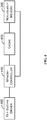
- FIG. 1 illustrates an example of a suitable computing system environment 100 on which aspects of the subject matter described herein may be implemented.
- the computing system environment 100 is only one example of a suitable computing environment and is not intended to suggest any limitation as to the scope of use or functionality of aspects of the subject matter described herein. Neither should the computing environment 100 be interpreted as having any dependency or requirement relating to any one or combination of components illustrated in the exemplary operating environment 100.
- aspects of the subject matter described herein are operational with numerous other general purpose or special purpose computing system environments or configurations.
- Examples of well-known computing systems, environments, or configurations that may be suitable for use with aspects of the subject matter described herein comprise personal computers, server computers--whether on bare metal or as virtual machines--, hand-held or laptop devices, multiprocessor systems, microcontroller-based systems, set-top boxes, programmable and non-programmable consumer electronics, network PCs, minicomputers, mainframe computers, personal digital assistants (PDAs), gaming devices, printers, appliances including set-top, media center, or other appliances, automobile-embedded or attached computing devices, other mobile devices, phone devices including cell phones, wireless phones, and wired phones, distributed computing environments that include any of the above systems or devices, and the like. While various embodiments may be limited to one or more of the above devices, the term computer is intended to cover the devices above unless otherwise indicated.
- aspects of the subject matter described herein may be described in the general context of computer-executable instructions, such as program modules, being executed by a computer.
- program modules include routines, programs, objects, components, data structures, and so forth, which perform particular tasks or implement particular abstract data types.
- aspects of the subject matter described herein may also be practiced in distributed computing environments where tasks are performed by remote processing devices that are linked through a communications network.
- program modules may be located in both local and remote computer storage media including memory storage devices.
- the functionality described herein may be performed, at least in part, by one or more hardware logic components.
- illustrative types of hardware logic components include Field-programmable Gate Arrays (FPGAs), Program-specific Integrated Circuits (ASICs), Program-specific Standard Products (ASSPs), System-on-a-chip systems (SOCs), Complex Programmable Logic Devices (CPLDs), and the like.
- an exemplary system for implementing aspects of the subject matter described herein includes a general-purpose computing device in the form of a computer 110.
- a computer may include any electronic device that is capable of executing an instruction.
- Components of the computer 110 may include a processing unit 120, a system memory 130, and one or more system buses (represented by system bus 121) that couples various system components including the system memory to the processing unit 120.
- the system bus 121 may be any of several types of bus structures including a memory bus or memory controller, a peripheral bus, and a local bus using any of a variety of bus architectures.
- such architectures include Industry Standard Architecture (ISA) bus, Micro Channel Architecture (MCA) bus, Enhanced ISA (EISA) bus, Video Electronics Standards Association (VESA) local bus, Peripheral Component Interconnect (PCI) bus also known as Mezzanine bus, Peripheral Component Interconnect Extended (PCI-X) bus, Advanced Graphics Port (AGP), and PCI express (PCIe).
- ISA Industry Standard Architecture
- MCA Micro Channel Architecture
- EISA Enhanced ISA
- VESA Video Electronics Standards Association
- PCI Peripheral Component Interconnect
- PCI-X Peripheral Component Interconnect Extended
- AGP Advanced Graphics Port
- PCIe PCI express
- the processing unit 120 may be connected to a hardware security device 122.
- the security device 122 may store and be able to generate cryptographic keys that may be used to secure various aspects of the computer 110.
- the security device 122 may comprise a Trusted Platform Module (TPM) chip, TPM Security Device, or the like.
- TPM Trusted Platform Module
- the computer 110 typically includes a variety of computer-readable media.
- Computer-readable media can be any available media that can be accessed by the computer 110 and includes both volatile and nonvolatile media, and removable and non-removable media.
- Computer-readable media may comprise computer storage media and communication media.
- Computer storage media includes both volatile and nonvolatile, removable and non-removable media implemented in any method or technology for storage of information such as computer-readable instructions, data structures, program modules, or other data.
- Computer storage media includes RAM, ROM, EEPROM, solid state storage, flash memory or other memory technology, CD-ROM, digital versatile discs (DVDs), Blu-ray Disc (BD) or other optical disk storage, magnetic cassettes, magnetic tape, magnetic disk storage or other magnetic storage devices, or any other medium which can be used to store the desired information and which can be accessed by the computer 110.
- Computer storage media does not include communication media.
- Communication media typically embodies computer-readable instructions, data structures, program modules, or other data in a modulated data signal such as a carrier wave or other transport mechanism and includes any information delivery media.
- modulated data signal means a signal that has one or more of its characteristics set or changed in such a manner as to encode information in the signal.
- communication media includes wired media such as a wired network or direct wired connection, and wireless media such as acoustic, RF, infrared and other wireless media. Combinations of any of the above should also be included within the scope of computer-readable media.
- the system memory 130 may include computer storage media in the form of volatile and/or nonvolatile memory such as read only memory (ROM) 131 and random access memory (RAM) 132.
- Nonvolatile memory may be substituted for some or all of the ROM 131 and/or the RAM 132.
- memristor memory, phase-change memory (PCM), or some other type of nonvolatile memory may be used instead of, or in addition to, the ROM 131 and/or the RAM 132.
- a basic input/output system 133 (BIOS), containing the basic routines that help to transfer information between elements within computer 110, such as during start-up, is typically stored in ROM 131.
- RAM 132 typically contains data and/or program modules that are immediately accessible to and/or presently being operated on by processing unit 120.
- FIG. 1 illustrates operating system 134, application programs 135, other program modules 136, and program data 137.
- the computer 110 may also include other removable/non-removable, volatile/nonvolatile computer storage media.
- FIG. 1 illustrates a hard disk drive 141 that reads from or writes to non-removable, nonvolatile magnetic media, a magnetic disk drive 151 that reads from or writes to a removable, nonvolatile magnetic disk 152, and an optical disc drive 155 that reads from or writes to a removable, nonvolatile optical disc 156 such as a CD ROM, DVD, BD, or other optical media.
- memristor memory phase-change memory, or some other type of nonvolatile memory may be used instead of, or in addition to, the hard drive 141.
- removable/non-removable, volatile/nonvolatile computer storage media that can be used in the exemplary operating environment include magnetic tape cassettes, flash memory cards and other solid state storage devices, digital versatile discs, other optical discs, digital video tape, solid state RAM, solid state ROM, and the like.
- the hard disk drive 141 may be connected to the system bus 121 through the interface 140, and magnetic disk drive 151 and optical disc drive 155 may be connected to the system bus 121 by an interface for removable nonvolatile memory such as the interface 150.
- hard disk drive 141 is illustrated as storing operating system 144, application programs 145, other program modules 146, and program data 147. Note that these components can either be the same as or different from operating system 134, application programs 135, other program modules 136, and program data 137. Operating system 144, application programs 145, other program modules 146, and program data 147 are given different numbers herein to illustrate that they may be different copies.
- a user may enter commands and information into the computer 110 through input devices such as a keyboard 162 and pointing device 161, commonly referred to as a mouse, trackball, or touch pad.
- Other input devices may include a microphone (e.g., for inputting voice or other audio), joystick, game pad, satellite dish, scanner, a touch-sensitive screen, a writing tablet, a camera (e.g., for inputting gestures or other visual input), or the like.
- These and other input devices are often connected to the processing unit 120 through a user input interface 160 that is coupled to the system bus, but may be connected by other interface and bus structures, such as a parallel port, game port or a universal serial bus (USB).
- USB universal serial bus
- NUI Natural User Interface
- a NUI may rely on speech recognition, touch and stylus recognition, gesture recognition both on screen and adjacent to the screen, air gestures, head and eye tracking, voice and speech, vision, touch, gestures, machine intelligence, and the like.
- NUI technology that may be employed to interact with a user include touch sensitive displays, voice and speech recognition, intention and goal understanding, motion gesture detection using depth cameras (such as stereoscopic camera systems, infrared camera systems, RGB camera systems, and combinations thereof), motion gesture detection using accelerometers/gyroscopes, facial recognition, 3D displays, head, eye, and gaze tracking, immersive augmented reality and virtual reality systems, as well as technologies for sensing brain activity using electric field sensing electrodes (EEG and related methods).
- depth cameras such as stereoscopic camera systems, infrared camera systems, RGB camera systems, and combinations thereof
- motion gesture detection using accelerometers/gyroscopes such as stereoscopic camera systems, infrared camera systems, RGB camera systems, and combinations thereof
- accelerometers/gyroscopes such as stereoscopic camera systems, infrared camera systems, RGB camera systems, and combinations thereof
- facial recognition such as stereoscopic camera systems, infrared camera systems, RGB camera systems, and combinations thereof
- 3D displays
- a monitor 191 or other type of display device is also connected to the system bus 121 via an interface, such as a video interface 190.
- computers may also include other peripheral output devices such as speakers 197 and printer 196, which may be connected through an output peripheral interface 195.
- the computer 110 may operate in a networked environment using logical connections to one or more remote computers, such as a remote computer 180.
- the remote computer 180 may be a personal computer, a server, a router, a network PC, a peer device or other common network node, and typically includes many or all of the elements described above relative to the computer 110, although only a memory storage device 181 has been illustrated in FIG. 1 .
- the logical connections depicted in FIG. 1 include a local area network (LAN) 171 and a wide area network (WAN) 173, but may also include phone networks, near field networks, and other networks.
- LAN local area network
- WAN wide area network
- Such networking environments are commonplace in offices, enterprise-wide computer networks, intranets, and the Internet.
- the computer 110 When used in a LAN networking environment, the computer 110 is connected to the LAN 171 through a network interface or adapter 170. When used in a WAN networking environment, the computer 110 may include a modem 172 or other means for establishing communications over the WAN 173, such as the Internet.
- the modem 172 which may be internal or external, may be connected to the system bus 121 via the user input interface 160 or other appropriate mechanism.
- program modules depicted relative to the computer 110, or portions thereof may be stored in the remote memory storage device.
- FIG. 1 illustrates remote application programs 185 as residing on memory device 181. It will be appreciated that the network connections shown are exemplary and other means of establishing a communications link between the computers may be used.
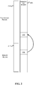
- FIGS. 2 and 5 are block diagrams that generally represent nonvolatile memory in accordance with aspects of the subject matter described herein.
- the nonvolatile memory 205 may include an array of memory storage elements that may be accessed by addresses.
- a memory device that includes the nonvolatile memory 205 may be addressed using memory primitives.
- the memory primitives used to access the nonvolatile memory 205 may be similar or identical to those used to access volatile memory such as RAM.
- Fast nonvolatile memory may be attached to a memory bus.
- some types of nonvolatile memory perform 2-4 times slower than RAM and a couple of orders of magnitude faster than flash memory or hard disk storage. These types of nonvolatile memory may have low latency and high data transfer rates that may benefit more by being attached to a memory bus than being attached to a storage bus.
- the nonvolatile memory 205 has been divided into a file system region 210 and a memory region 211.
- the illustrated sizes of these regions are exemplary only. In other implementations, for example, these sizes may be greatly varied from the sizes shown in FIG. 2 .
- nonvolatile memory 205 may be implemented using one or more subsystems.
- the system may include multiple subsystems to access the nonvolatile memory.
- a storage system may include one or more hardware and/or software components that organize data that is persisted.
- the size of the file system region 210 and the size of the memory region 211 may be set or reset, for example, during a configuration operation.
- a configuration operation may occur prior to or after installing an operation system to size or resize memory regions as desired.
- An operating system may be configured to look for configuration data in a pre-defined location of the nonvolatile memory 205.
- the configuration data may indicate how the nonvolatile memory is to be divided between file system data and memory available for other uses.
- the memory region 211 is a portion of the nonvolatile memory 205 that has been set aside to provide additional main memory for a computer. This memory may be used in lieu of, or in addition to, any RAM or other volatile memory of the computer.
- the file system region 210 is a portion of the nonvolatile memory 205 that has been set aside for file system data. Although physically, memory elements in this region may be accessed in the same manner as memory elements in the memory region 211 are accessed, file system components acting in conjunction with memory hardware may enforce certain rules regarding these accesses as described in more detail below.
- a block of data from a hard disk may be copied into main memory. Once in main memory, the data may be modified. At some point, the block of data as modified is written from the main memory to the hard disk.
- a file system may be structured to avoid some of the copying that occurs in traditional file systems. For example, referring to FIG. 2 , an application may seek to obtain data that is in the block 215. Instead of copying the data in the block 215 to memory in the block 216, the file system may request that memory hardware create an alias between the block 216 and the block 215. When an alias is created, an operation that attempts to read the block 216 obtains the data from the block 215 except when certain conditions are met.
- a write to the block 216 causes data to be written to the block 216.
- the memory hardware may wait to copy the data written to the block 216 to the block 215 until a time after the write of the data to the block 216.
- the memory hardware may wait for an explicit command from the file system before copying the data written to the block 216 to the block 215. This allows the file system to be more involved when writes occur to the nonvolatile memory 205.
- the block 215 may be implemented by a plurality of sub blocks.
- a sub block may be a small, fixed-size of memory that can be accessed on a memory architecture that uses the nonvolatile memory 205.
- a block may correspond to a page of memory while a sub block may correspond to a cache line.
- an alias when an alias is set up between the block 216 and the block 215, physically an alias may be set up between each sub block of the block 216 and its corresponding sub block of the block 215. This results in a plurality of aliases between memory elements of the blocks 216 and 215.
- the sub blocks that include the portion may be determined, and the aliases associated with those sub blocks may be severed. This severing may occur at any time prior to a subsequent read of the block 216.
- data for the read is retrieved from the block 215 where the aliases have not been severed and from block 216 where the aliases have been severed.
- the sub blocks that include the portion may be determined, and the aliases associated with those sub blocks may be severed. This severing may occur at any time prior to a subsequent read of the block 216.
- data for the read is retrieved from the block 215 where the aliases have not been severed and via block 216 where the aliases have been severed.
- the data in the sub block of block 215 may be preserved so that it may be obtained when accessing the corresponding sub block of block 216 (or any other sub block that is aliased to the sub block of block 215).
- Preserving the data may include, for example, copying the data to a location allocated to block 216, copying the data to a new location and updating the alias of block 216 to point to the new location, keeping the data in its current location and updating mapping structures associated with block 215 so that a read to block 215 obtains the changed data, or the like. This behavior keeps the data obtainable via block 216 unchanged even when the data of block 215 changes.
- aliases are broken as outlined above. In another implementation, aliases are broken in response to writing to the block 216, but not in response to writing to the block 215. In another implementation, aliases are broken in response to writing to the block 215, but not in response to an attempted write to the block 216.
- the implementation followed in a particular system may be configurable via hardware or software, be hard-wired or hard-coded, or the like.
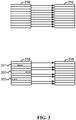
- FIG. 3 is a block diagram that generally represents various states of aliases between sub blocks of the memory blocks of FIG. 2 in accordance with aspects of the subject matter described herein.
- an alias is set up between the block 216 and the block 215, this may cause a plurality of aliases to be set up between the sub blocks of block 216 and sub blocks of block 215.
- a read request for data addressed to block 216 is received in this state, the read is satisfied from the data in the block 215.
- the block 316 represents the block 216 after data has been written to the block 216. In particular, data has been written to the sub blocks 301-303. In conjunction with writing data to create the block 316, aliases for the sub blocks 301-303 have been severed. A read addressed to block 316 will retrieve data from the block 215 where the aliases have not been severed and will retrieve data from the block 316 where the aliases have been severed (e.g., for sub blocks 301-303).
- a memory controller e.g., the memory controller 410 of FIG. 4
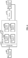
- FIGS. 4 and 6 are block diagrams that generally represents exemplary components of systems configured in accordance with aspects of the subject matter described herein.
- the components illustrated in FIGS. 4 and 6 are exemplary and are not meant to be all-inclusive of components that may be needed or included.
- the number of components may differ in other embodiments without departing from the spirit or scope of aspects of the subject matter described herein.
- the components described in conjunction with FIGS. 4 and 6 may be included in other components (shown or not shown) or placed in subcomponents without departing from the spirit or scope of aspects of the subject matter described herein.
- the components and/or functions described in conjunction with FIGS. 4 and 6 may be distributed across multiple devices.
- the cache 415 may include memory elements that cache data from the nonvolatile memory 205.
- the cache may comprise dynamic RAM (DRAM), static RAM (SRAM), or some other type of volatile or nonvolatile memory.
- the cache 415 may be omitted. In some implementations, there may be more than one level of cache.
- the memory controller 410 may include a circuit for accessing data on the nonvolatile memory 205. Access as used herein may include reading data, writing data, deleting data, updating data, a combination including two or more of the above, and the like. In one implementation, the memory controller 410 may access the nonvolatile memory 205 using the cache 415 only. In other words, in this implementation, whenever the memory controller 410 reads or writes, it may send the read or write to the cache 415. For a read, the cache 415 may then provide the data from the cache 415 if the cache has the data or obtain the data from the nonvolatile memory 205 and then provide the data if the cache does not have the data. For a write, the cache 415 may store the written data on the cache 415 and may flush the cache to the nonvolatile memory 205 according to caching policies.
- the memory controller 410 may also act as a controller for the cache 415 and may obtain data from the cache 415 or the nonvolatile memory 205 as appropriate. In this implementation, the memory controller 410 may also cause the cache 415 to write data to the nonvolatile memory 205 according to caching policies.
- the memory controller 410 may include an interface by which the file system driver 405 may send requests and receive data.
- this interface may allow communications including the following:
- alias is not changed to the new block 505
- a read of data in the memory block 216 may return with the changed data. This may cause problems if, for example, the program expects that the block 216 is still aliased to the data that has not changed (e.g., the data in block 505).
- the memory controller 410 may be structured to receive a request to re-alias a block that is currently aliased. For example, in one implementation, the memory controller 410 may be structured to receive a request to re-alias memory within a specified range to memory within another specified range. In this implementation, the memory controller 410 may determine all aliases that point to the first specified range and re-alias these aliases to point to the second specified range.
- the memory controller 410 may be structured to receive a request to re-alias a specific alias to a new location.
- the memory controller 410 may be structured to receive a request to re-alias one of the aliases for the sub blocks of block 215.
- the file system driver 405 may include logic to determine all aliases for the portion of memory in conjunction with sending commands to re-alias each alias to the memory controller 410.
- a memory controller may be structured to perform a re-aliasing operation in a "safe" manner. Safe in this context means that logically the re-aliasing operation is performed prior to performing other operations that were received subsequent to the re-aliasing request. In one implementation, the memory controller may physically perform other operations as long as the file system driver 405 is unable, using any set of operations, to detect that the re-aliasing operation was performed out-of-order relative to when it was received.
- a memory controller may implement re-aliasing in other ways without departing from the spirit or scope of aspects of the subject matter described herein.
- a memory controller may be structured to receive a move block command and may automatically re-alias aliases that point to the block when the block is moved.
- a memory controller may be structured to receive a move block command and may modify internal mapping elements to logically move the block without physically copying the block to another location.
- moving the block in this way may negate the need to perform re-aliasing. For example, if an alias points to the block regardless of mapping information, then when mapping information is changed to move the block, the alias still points at the block.
- a memory controller may be structured to receive a re-alias command that is not automatically triggered by a move block command.
- the file system driver 405 may explicitly request re-aliasing in addition to requesting moving a block as appropriate.
- the file system driver 405 may be a software and/or hardware component that gives commands and receives responses from the memory controller 410.
- the file system driver 405 may be part of a storage stack of a file system and 405 may communicate with the memory controller 410 over a system bus or other communication link.
- the file system driver 405 may provide an interface to the storage stack of a file system that makes the nonvolatile memory 205 appear like other storage (e.g., hard disk, flash memory, other nonvolatile or volatile memory, or the like) available to the storage stack.
- the teachings herein may also be applied to implementations in which the file system region and the memory region are implemented using other memory configurations.
- the file system region and/or the memory region may be implemented with volatile, nonvolatile, or a combination of volatile and nonvolatile memory.
- the file system region may be implemented on a different memory type than the memory region.
- teachings herein may be applied, for example, to aliases from volatile to volatile memory, aliases from volatile to nonvolatile memory, aliases from nonvolatile to volatile memory, systems that have two or more different types of aliases (e.g., nonvolatile to nonvolatile, volatile to nonvolatile, etc.), and the like.
- a memory controller such as the memory controller 410 of FIG. 4 may provide an interface that allows aliases to be used, created, re-aliased, and so forth and to perform the other actions described herein without departing from the spirit or scope of aspects of the subject matter described herein.
- a circuit may include only physical components such as resistor, transistors, capacitors, voltage sources, current sources, switches, inductors, and the like. One or more of the physical components may be integrated into one or more chips. In another embodiment, a circuit may include physical components together with instructions that indicate how the physical components are to operate. The instructions may be encoded in volatile or nonvolatile memory.
- circuits of the memory controller 605 are exemplary and are not meant to be all-inclusive of circuits that may be needed or included. Furthermore, the number of circuits may differ in other embodiments without departing from the spirit or scope of aspects of the subject matter described herein. In some embodiments, the circuits described in conjunction with FIG. 6 may be included in other circuits or placed in sub circuits without departing from the spirit or scope of aspects of the subject matter described herein.
- the interface 610 may include a structure by which the file system driver 405 may communicate with the memory controller 605.
- the interface 610 may allow the file system driver to communicate with the memory controller 605 via electrical, optical, or other signals that encode requests and responses to those requests.
- the interface 610 may also be structured to allow communications as indicated in conjunction with FIG. 4 .
- the interface 610 may be structured to receive a request to create an alias between a storage system block of memory and a main memory block of memory.
- a storage system block of memory may be used, for example, in maintaining storage system data and may correspond to the file system region 210 of FIG. 2 for example.
- a main memory block may be used for main memory of the computer and may correspond to the memory region 211 of FIG. 2 .
- the aliasing circuit 615 may be structured to create an alias between a storage system block of memory and a main memory block of memory as requested by the file system driver. As indicated previously, creating an alias between these memory blocks may include creating a plurality of aliases between sub blocks of these blocks.
- the aliasing circuit 615 may be further structured to sever an alias to a sub block in response to a request to write to the sub block. In one implementation, the aliasing circuit 615 may wait to sever the alias to the sub block until just before servicing a request to read from the sub block.
- the aliasing circuit 615 may also be structured to re-alias an aliased block in response to a request to move the aliased block, for example.
- the copying circuit 616 may be structured to respond to a request to copy a main memory block to a new location. In one implementation, the copying circuit 616 may respond by physically copying data in the main memory block to the new location. In another implementation, copying circuit 616 may logically copy the data in the main memory block to the new location by leaving the data in the main memory block and updating mapping elements as previously described.
- the zeroing circuit 618 is structured to respond to a request to zero a requested range of memory.
- the requested range of memory may include some or all of memory used for main memory.
- the zeroing circuit 618 may zero a requested range of the memory by flagging that the requested range is zeroed.
- the zeroing circuit 618 may wait to physically zero a portion of the requested range until a read or write request for the portion is received by the memory controller 605.
- the zeroing circuit 618 may place zeroes in a read cache in response to a read for memory that has been flagged as zeroed.
- the zeroing circuit 618 may not actually physically zero the flagged range but the read for memory may return zeroes as it is serviced from the read cache.
- the zeroing circuit may wait to zero (e.g., physically or logically) the memory until after receiving an indication of restart of a computer hosting the main memory.
- the retrieval circuit 617 may be structured to respond to a read request of the file system driver. Where some aliases have been severed, the retrieval circuit 617 may respond to a request by obtaining first data from sub blocks of the storage system block where aliases have not been severed and to obtain second data from sub blocks of the main memory block where aliases have been severed and then combining the first data and the second data to respond to the read request.
- a main memory block of memory may include a page of memory that may be broken into sub blocks where each sub block corresponds to a cache line.
- FIGS. 7-9 are flow diagrams that generally represent exemplary actions that may occur in accordance with aspects of the subject matter described herein.
- the methodology described in conjunction with FIGS. 7-9 is depicted and described as a series of acts. It is to be understood and appreciated that aspects of the subject matter described herein are not limited by the acts illustrated and/or by the order of acts. In one embodiment, the acts occur in an order as described below. In other embodiments, however, two or more of the acts may occur in parallel or in another order. In other embodiments, one or more of the actions may occur with other acts not presented and described herein. Furthermore, not all illustrated acts may be required to implement the methodology in accordance with aspects of the subject matter described herein. In addition, those skilled in the art will understand and appreciate that the methodology could alternatively be represented as a series of interrelated states via a state diagram or as events.
- FIG. 7 is a flow diagram that generally represents exemplary actions that may occur in conjunction with creating an alias from a memory controller perspective in accordance with aspects of the subject matter described herein. At block 705, the actions begin.
- a request to create an alias is received.
- the memory controller 605 may receive a request to alias a block of memory via the interface 610. This request may come from the file system driver 405. The request may request the creation of an alias between a storage system block of memory and a main memory block of memory.
- one or more aliases may be created.
- the aliasing circuit 615 may create an alias between the two blocks of memory and/or may create aliases between corresponding sub blocks of the two blocks of memory.
- actions include, for example, any of the actions described herein with respect to a memory controller.
- FIG. 8 is a flow diagram that generally represents exemplary actions that may occur in conjunction with obtaining data for an aliased block from a memory controller perspective in accordance with aspects of the subject matter described herein. At block 805, the actions begin.
- a read request for an aliased block is received.
- the memory controller 605 may receive a request to read the data in the block 216.
- the request may come from the file system driver 405 and may be communicated via the interface 610.
- data may be obtained from an appropriate block or sub blocks. For example, referring to FIGS. 3 and 6 , if none of the aliases between the sub blocks of blocks 216 and 215 has been severed, then the retrieval circuit 617 may obtain data from the block 215. If aliases have been severed as shown in FIG. 3 , then the retrieval circuit 617 may obtain the data from sub blocks of the block 215 where the aliased have not been severed and from the sub blocks 301, 302, and 303, where the aliases have been severed.
- data is combined if needed. If some but not all of the aliases of sub blocks have been severed, data from sub blocks that are included in different blocks may be combined in response to the request. For example, referring to FIGS. 3 and 6 , if none of the aliases between the sub blocks of blocks 216 and 215 have been severed, then the retrieval circuit 617 may have no need to combine sub blocks from different blocks of memory; otherwise, the retrieval circuit 617 may combine data from the sub blocks 301, 302, and 303 with data from the sub blocks of block 215 where the aliases have not been severed.
- the data is provided in response to the request.
- the memory controller 605 may provide the data to the file system driver 405 via the interface 610.
- FIG. 9 is a flow diagram that shows exemplary actions that may occur on a component accessing memory via a memory controller in accordance with aspects of the subject matter described herein. At block 905, the actions begin.
- a request to create an alias is sent.
- the file system driver 405 may send a request to create an alias between two blocks of memory. This request may be sent to the memory controller 605 via the interface 610.
- a request for the aliased data may be sent.
- the file system driver 405 may send a request addressed to the block 216. This request may also be sent to the memory controller 605 via the interface 610.
- data may be received.
- the file system driver 405 may receive data that has been obtained from the block 215.
Claims (9)
- Contrôleur de mémoire (410) comprenant :un circuit permettant d'accéder à des données sur une mémoire non volatile (205),une interface (610) structurée pour recevoir une demande provenant d'un pilote de système de fichiers (405) afin de créer un alias entre un bloc de système de stockage (215) de mémoire et un bloc de mémoire principale (216) de la mémoire, le bloc de système de stockage de mémoire étant destiné à être utilisé dans la tenue à jour des données du système de stockage, le bloc de mémoire principale de la mémoire étant destiné à être utilisé pour la mémoire principale d'un ordinateur,un circuit de création d'alias (615) structuré pour créer l'alias entre le bloc de système de stockage de mémoire et le bloc de mémoire principale de la mémoire, etun circuit de récupération (617) structuré pour récupérer des données auprès du bloc de système de stockage en réponse à une demande de lecture de données concernant le bloc de mémoire principale tant que l'alias n'est pas rompu,dans lequel la mémoire non volatile (205) est divisée en une zone de système de fichiers (210) et une zone de mémoire (211), et où le bloc de système de stockage de mémoire (215) est situé dans la zone de système de fichiers (210) et le bloc de mémoire principale est situé dans la zone de mémoire (211),caractérisé en ce que des éléments de mémoire dans la zone de système de fichiers sont accessibles physiquement de la même manière que des éléments de mémoire dans la zone de mémoire, et en ce que le circuit de création d'alias, qui est structuré pour créer un alias entre le bloc de système de stockage de mémoire et le bloc de mémoire principale de la mémoire, comprend le circuit de création d'alias structuré pour créer un alias à partir de chaque sous bloc du bloc de mémoire principale de la mémoire vers chaque sous bloc correspondant du bloc de système de stockage de mémoire et pour tenir à jour chaque alias jusqu'à ce qu'il soit rompu.
- Contrôleur de mémoire (410) selon la revendication 1, dans lequel le circuit de récupération (617) est en outre structuré en réponse à la demande de lecture pour récupérer des premières données à partir de sous blocs du bloc de système de stockage ou des alias n'ont pas été rompus et pour récupérer des secondes données à partir de sous blocs du bloc de mémoire principale (216) ou des alias ont été rompus, le circuit de récupération étant en outre structuré pour combiner les premières données et les secondes données afin de répondre à la demande de lecture.
- Contrôleur de mémoire (410) selon la revendication 1, dans lequel le circuit de création d'alias (615) est en outre structuré pour rompre un alias à partir d'un premier sous bloc sur un second sous bloc en réponse à une demande d'écriture sur le premier sous bloc ou d'écriture sur le second sous bloc.
- Contrôleur de mémoire (410) selon la revendication 3, dans lequel le circuit de création d'alias (615) est en outre structuré pour rompre l'alias à partir du premier sous bloc sur le second sous bloc après la demande d'écriture et juste avant de répondre à une demande de lecture à partir du premier sous bloc.
- Contrôleur de mémoire (410) selon la revendication 1, comprenant en outre un circuit de copie (616) structuré pour répondre à une demande de copie du bloc de mémoire principale sur un nouvel emplacement, le circuit de copie étant en outre structuré pour répondre à une demande de copie du bloc de mémoire principale (216) sur un nouvel emplacement en laissant des données dans le bloc de mémoire principale et en modifiant des éléments de mappage de sorte à ce que les données soient renvoyées à la demande depuis le nouvel emplacement.
- Contrôleur de mémoire (410) selon la revendication 1, comprenant en outre un circuit de mise à zéro (618) structuré pour répondre à une requête de mise à zéro d'une plage requise de mémoire qui inclut tout ou partie de la mémoire principale, le circuit de mise à zéro étant structuré pour mettre à zéro une plage requise de la mémoire en indiquant que la plage requise est mise à zéro et, ensuite, en réponse à une demande de lecture qui met en jeu la plage requise de mémoire, en plaçant des valeurs nulles dans une antémémoire de lecture.
- Contrôleur de mémoire (410) selon la revendication 1, dans lequel le circuit de création d'alias (615) est en outre structuré pour créer de nouveau un alias d'un bloc déjà créé en alias en réponse à une demande de déplacement du bloc créé en alias.
- Procédé mis en œuvre sur ordinateur, le procédé comprenant :la réception d'une demande, au niveau d'une interface de contrôleur mémoire appartenant à un contrôleur mémoire (405) conçu pour accéder à une mémoire non volatile (205), en provenance d'un pilote de système de fichiers (405) afin de créer un alias entre un bloc de système de stockage (215) de mémoire et un bloc de mémoire principale (216) de la mémoire, le bloc de système de stockage de mémoire étant destiné à être utilisé dans la tenue à jour des données du système de stockage, le bloc de mémoire principale de la mémoire étant destiné à être utilisé pour la mémoire principale d'un ordinateur,la mise à jour d'une structure de circuit pour créer l'alias entre le bloc de système de stockage de mémoire et le bloc de mémoire principale de la mémoire, etla fourniture des données à partir du bloc de système de stockage de mémoire en réponse à une demande de données, la demande indiquant le bloc de mémoire principale de la mémoire,dans lequel la mémoire non volatile (205) est divisée en une zone de système de fichiers (210) et une zone de mémoire (211), et où le bloc de système de stockage de mémoire (215) est situé dans la zone de système de fichiers (210) et le bloc de mémoire principale est situé dans la zone de mémoire (211),caractérisé en ce que des éléments de mémoire dans la zone de système de fichiers sont accessibles physiquement de la même manière que des éléments de mémoire dans la zone de mémoire, et en ce que lorsqu'un alias est établi entre le bloc de mémoire principale (216) et le bloc de système de stockage (215), un alias est créé physiquement entre chaque sous bloc du bloc (216) et son sous bloc correspondant du bloc (215), et chaque alias est tenu à jour jusqu'à ce qu'il soit rompu.
- Support de stockage sur ordinateur comportant des instructions exécutables par ordinateur, qui, lorsqu'elles sont exécutées sur le contrôleur de mémoire de la revendication 1, effectuent des actions comprenant :l'envoi d'une demande à partir d'un pilote système de fichiers d'un système d'exploitation à une interface de contrôleur mémoire (410) qui est conçu pour accéder à une mémoire non volatile (205), la demande requérant la création d'un alias entre un premier bloc de mémoire (215) et un second bloc de mémoire principale (216), le premier bloc de mémoire étant destiné à être utilisé pour la tenue à jour de données de système de stockage, le second bloc de mémoire étant destiné à être utilisé pour la mémoire principale d'un ordinateur,l'envoi, à partir du pilote système de fichiers (405) au contrôleur de mémoire, d'une demande de données, la demande indiquant le premier bloc de mémoire, eten réponse à la demande de données, la réception, en provenance du contrôleur de mémoire, de données provenant du second bloc de mémoire,dans lequel la mémoire non volatile divisée en une zone de système de fichiers (210) et une zone de mémoire (200), et où le bloc de système de stockage de la mémoire est situé dans la zone de système de fichiers et le bloc de mémoire principale est situé dans la zone de mémoire,caractérisé en ce que des éléments de mémoire dans la zone de système de fichiers sont accessibles physiquement de la même manière que des éléments de mémoire dans la zone de mémoire, et en ce que lorsqu'un alias est établi entre le bloc de mémoire principale (216) et le bloc de système de stockage (215), un alias est créé physiquement entre chaque sous bloc du bloc (216) et son sous bloc correspondant du bloc (215), et chaque alias est tenu à jour jusqu'à ce qu'il soit rompu.
Applications Claiming Priority (3)
| Application Number | Priority Date | Filing Date | Title |
|---|---|---|---|
| US201361828636P | 2013-05-29 | 2013-05-29 | |
| US14/036,298 US9678689B2 (en) | 2013-05-29 | 2013-09-25 | Storage systems and aliased memory |
| PCT/US2014/039634 WO2014193862A2 (fr) | 2013-05-29 | 2014-05-28 | Systèmes de stockage et mémoire à alias |
Publications (2)
| Publication Number | Publication Date |
|---|---|
| EP3005126A2 EP3005126A2 (fr) | 2016-04-13 |
| EP3005126B1 true EP3005126B1 (fr) | 2021-03-31 |
Family
ID=51986493
Family Applications (1)
| Application Number | Title | Priority Date | Filing Date |
|---|---|---|---|
| EP14802963.0A Active EP3005126B1 (fr) | 2013-05-29 | 2014-05-28 | Systèmes de stockage et mémoire à alias |
Country Status (8)
| Country | Link |
|---|---|
| US (2) | US9678689B2 (fr) |
| EP (1) | EP3005126B1 (fr) |
| JP (1) | JP6324494B2 (fr) |
| CN (1) | CN105339909B (fr) |
| BR (1) | BR112015029108B1 (fr) |
| ES (1) | ES2865575T3 (fr) |
| RU (1) | RU2669008C2 (fr) |
| WO (1) | WO2014193862A2 (fr) |
Families Citing this family (7)
| Publication number | Priority date | Publication date | Assignee | Title |
|---|---|---|---|---|
| US9678689B2 (en) * | 2013-05-29 | 2017-06-13 | Microsoft Technology Licensing, Llc | Storage systems and aliased memory |
| US10049052B2 (en) * | 2014-10-27 | 2018-08-14 | Nxp Usa, Inc. | Device having a cache memory |
| US9740414B2 (en) | 2015-10-29 | 2017-08-22 | Pure Storage, Inc. | Optimizing copy operations |
| KR20170076878A (ko) * | 2015-12-24 | 2017-07-05 | 에스케이하이닉스 주식회사 | 메모리 시스템 및 메모리 시스템의 동작 방법 |
| US10210088B2 (en) | 2015-12-28 | 2019-02-19 | Nxp Usa, Inc. | Computing system with a cache invalidation unit, a cache invalidation unit and a method of operating a cache invalidation unit in a computing system |
| US11237758B2 (en) * | 2016-08-06 | 2022-02-01 | Wolley Inc. | Apparatus and method of wear leveling for storage class memory using address cache |
| US10387304B2 (en) * | 2017-12-28 | 2019-08-20 | Intel Corporation | Virtual transfer of data between memory and storage domains |
Citations (2)
| Publication number | Priority date | Publication date | Assignee | Title |
|---|---|---|---|---|
| US20050138307A1 (en) * | 2003-12-18 | 2005-06-23 | Grimsrud Knut S. | Storage performance improvement using data replication on a disk |
| WO2013048483A1 (fr) * | 2011-09-30 | 2013-04-04 | Intel Corporation | Hiérarchie de stockage de plate-forme avec une mémoire vive non volatile ayant des partitions configurables |
Family Cites Families (22)
| Publication number | Priority date | Publication date | Assignee | Title |
|---|---|---|---|---|
| US5119290A (en) * | 1987-10-02 | 1992-06-02 | Sun Microsystems, Inc. | Alias address support |
| JPH05158782A (ja) * | 1991-12-06 | 1993-06-25 | Hitachi Ltd | 記憶装置 |
| US6438672B1 (en) * | 1999-06-03 | 2002-08-20 | Agere Systems Guardian Corp. | Memory aliasing method and apparatus |
| RU2257609C2 (ru) * | 1999-10-21 | 2005-07-27 | Мацусита Электрик Индастриал Ко., Лтд. | Устройство доступа к полупроводниковой карте памяти, компьютерно-считываемый носитель записи, способ инициализации и полупроводниковая карта памяти |
| US6625725B1 (en) * | 1999-12-22 | 2003-09-23 | Intel Corporation | Speculative reuse of code regions |
| GB2372589B (en) * | 2001-02-21 | 2003-01-22 | 3Com Corp | Memory aliasing in a processor system |
| US7900017B2 (en) * | 2002-12-27 | 2011-03-01 | Intel Corporation | Mechanism for remapping post virtual machine memory pages |
| JP2004362464A (ja) * | 2003-06-06 | 2004-12-24 | Sony Corp | 不揮発メモリを利用したコンピュータシステム |
| US20110029723A1 (en) | 2004-08-06 | 2011-02-03 | Super Talent Electronics, Inc. | Non-Volatile Memory Based Computer Systems |
| US8417915B2 (en) * | 2005-08-05 | 2013-04-09 | Arm Limited | Alias management within a virtually indexed and physically tagged cache memory |
| US7872657B1 (en) * | 2006-06-16 | 2011-01-18 | Nvidia Corporation | Memory addressing scheme using partition strides |
| US7747817B2 (en) * | 2006-06-28 | 2010-06-29 | Unity Semiconductor Corporation | Performing data operations using non-volatile third dimension memory |
| JP4783229B2 (ja) * | 2006-07-19 | 2011-09-28 | パナソニック株式会社 | キャッシュメモリシステム |
| JP2009009665A (ja) * | 2007-06-29 | 2009-01-15 | Elpida Memory Inc | 半導体記憶装置 |
| US8074034B2 (en) * | 2007-07-25 | 2011-12-06 | Agiga Tech Inc. | Hybrid nonvolatile ram |
| US7855916B2 (en) | 2007-10-24 | 2010-12-21 | Rao G R Mohan | Nonvolatile memory systems with embedded fast read and write memories |
| US8250282B2 (en) * | 2009-05-14 | 2012-08-21 | Micron Technology, Inc. | PCM memories for storage bus interfaces |
| US8412987B2 (en) * | 2009-06-30 | 2013-04-02 | Micron Technology, Inc. | Non-volatile memory to store memory remap information |
| US20130033957A1 (en) * | 2011-08-04 | 2013-02-07 | Spar Food Machinery Manufacturing Co., Ltd. | Stirrer having Programmable Stirring Mode Control |
| WO2013101050A1 (fr) * | 2011-12-29 | 2013-07-04 | Intel Corporation | Mémoire multi-niveau à accès direct |
| US9552176B2 (en) | 2013-04-12 | 2017-01-24 | Microsoft Technology Licensing, Llc | Block storage using a hybrid memory device |
| US9678689B2 (en) * | 2013-05-29 | 2017-06-13 | Microsoft Technology Licensing, Llc | Storage systems and aliased memory |
-
2013
- 2013-09-25 US US14/036,298 patent/US9678689B2/en active Active
-
2014
- 2014-05-28 CN CN201480030762.4A patent/CN105339909B/zh active Active
- 2014-05-28 ES ES14802963T patent/ES2865575T3/es active Active
- 2014-05-28 JP JP2016516745A patent/JP6324494B2/ja active Active
- 2014-05-28 BR BR112015029108-2A patent/BR112015029108B1/pt active IP Right Grant
- 2014-05-28 RU RU2015151012A patent/RU2669008C2/ru active
- 2014-05-28 EP EP14802963.0A patent/EP3005126B1/fr active Active
- 2014-05-28 WO PCT/US2014/039634 patent/WO2014193862A2/fr active Application Filing
-
2017
- 2017-05-30 US US15/608,690 patent/US10216437B2/en active Active
Patent Citations (2)
| Publication number | Priority date | Publication date | Assignee | Title |
|---|---|---|---|---|
| US20050138307A1 (en) * | 2003-12-18 | 2005-06-23 | Grimsrud Knut S. | Storage performance improvement using data replication on a disk |
| WO2013048483A1 (fr) * | 2011-09-30 | 2013-04-04 | Intel Corporation | Hiérarchie de stockage de plate-forme avec une mémoire vive non volatile ayant des partitions configurables |
Also Published As
| Publication number | Publication date |
|---|---|
| RU2669008C2 (ru) | 2018-10-05 |
| CN105339909A (zh) | 2016-02-17 |
| US20170262207A1 (en) | 2017-09-14 |
| ES2865575T3 (es) | 2021-10-15 |
| WO2014193862A2 (fr) | 2014-12-04 |
| JP6324494B2 (ja) | 2018-05-16 |
| RU2015151012A (ru) | 2017-06-01 |
| US9678689B2 (en) | 2017-06-13 |
| BR112015029108B1 (pt) | 2022-05-17 |
| US10216437B2 (en) | 2019-02-26 |
| US20140359203A1 (en) | 2014-12-04 |
| EP3005126A2 (fr) | 2016-04-13 |
| CN105339909B (zh) | 2018-08-24 |
| BR112015029108A2 (pt) | 2017-07-25 |
| JP2016524228A (ja) | 2016-08-12 |
| WO2014193862A3 (fr) | 2015-04-09 |
Similar Documents
| Publication | Publication Date | Title |
|---|---|---|
| EP3005126B1 (fr) | Systèmes de stockage et mémoire à alias | |
| US20200301836A1 (en) | Storage system and method for accessing same | |
| US10896136B2 (en) | Storage system including secondary memory that predicts and prefetches data | |
| US9785545B2 (en) | Method and apparatus for providing dual memory access to non-volatile memory | |
| JP6190045B2 (ja) | 高性能でかつ低コストのフラッシュ変換層のためのシステムおよび方法 | |
| US11341059B2 (en) | Using multiple memory elements in an input-output memory management unit for performing virtual address to physical address translations | |
| US8595451B2 (en) | Managing a storage cache utilizing externally assigned cache priority tags | |
| US10782904B2 (en) | Host computing arrangement, remote server arrangement, storage system and methods thereof | |
| US20170255561A1 (en) | Technologies for increasing associativity of a direct-mapped cache using compression | |
| US8954707B2 (en) | Automatic use of large pages | |
| US10339021B2 (en) | Method and apparatus for operating hybrid storage devices | |
| US20190340129A1 (en) | Unified in-memory cache | |
| US10628048B2 (en) | Storage control device for controlling write access from host device to memory device | |
| US20230049799A1 (en) | Storage system and method for accessing same | |
| US20130173862A1 (en) | Method for cleaning cache of processor and associated processor | |
| US20170153994A1 (en) | Mass storage region with ram-disk access and dma access | |
| CN116034366A (zh) | 通过选择性数据移动防止ram访问模式攻击 | |
| US20220300424A1 (en) | Memory system, control method, and memory controller | |
| US20240053923A1 (en) | Write coalescing via hmb to optimize write performance | |
| TW202349214A (zh) | 輸入/輸出裝置的位址變換預取出 | |
| TWI569129B (zh) | 系統暫停方法、系統回復方法及應用其之電腦系統 |
Legal Events
| Date | Code | Title | Description |
|---|---|---|---|
| PUAI | Public reference made under article 153(3) epc to a published international application that has entered the european phase |
Free format text: ORIGINAL CODE: 0009012 |
|
| 17P | Request for examination filed |
Effective date: 20151021 |
|
| AK | Designated contracting states |
Kind code of ref document: A2 Designated state(s): AL AT BE BG CH CY CZ DE DK EE ES FI FR GB GR HR HU IE IS IT LI LT LU LV MC MK MT NL NO PL PT RO RS SE SI SK SM TR |
|
| AX | Request for extension of the european patent |
Extension state: BA ME |
|
| DAX | Request for extension of the european patent (deleted) | ||
| STAA | Information on the status of an ep patent application or granted ep patent |
Free format text: STATUS: EXAMINATION IS IN PROGRESS |
|
| 17Q | First examination report despatched |
Effective date: 20180102 |
|
| REG | Reference to a national code |
Ref country code: DE Ref legal event code: R079 Ref document number: 602014076185 Country of ref document: DE Free format text: PREVIOUS MAIN CLASS: G06F0012080000 Ipc: G06F0012086600 |
|
| RIC1 | Information provided on ipc code assigned before grant |
Ipc: G06F 12/0866 20160101AFI20200421BHEP |
|
| GRAP | Despatch of communication of intention to grant a patent |
Free format text: ORIGINAL CODE: EPIDOSNIGR1 |
|
| RIC1 | Information provided on ipc code assigned before grant |
Ipc: G06F 12/0866 20160101AFI20200430BHEP |
|
| STAA | Information on the status of an ep patent application or granted ep patent |
Free format text: STATUS: GRANT OF PATENT IS INTENDED |
|
| INTG | Intention to grant announced |
Effective date: 20200604 |
|
| GRAJ | Information related to disapproval of communication of intention to grant by the applicant or resumption of examination proceedings by the epo deleted |
Free format text: ORIGINAL CODE: EPIDOSDIGR1 |
|
| STAA | Information on the status of an ep patent application or granted ep patent |
Free format text: STATUS: EXAMINATION IS IN PROGRESS |
|
| GRAP | Despatch of communication of intention to grant a patent |
Free format text: ORIGINAL CODE: EPIDOSNIGR1 |
|
| STAA | Information on the status of an ep patent application or granted ep patent |
Free format text: STATUS: GRANT OF PATENT IS INTENDED |
|
| INTC | Intention to grant announced (deleted) | ||
| INTG | Intention to grant announced |
Effective date: 20201105 |
|
| GRAS | Grant fee paid |
Free format text: ORIGINAL CODE: EPIDOSNIGR3 |
|
| GRAA | (expected) grant |
Free format text: ORIGINAL CODE: 0009210 |
|
| STAA | Information on the status of an ep patent application or granted ep patent |
Free format text: STATUS: THE PATENT HAS BEEN GRANTED |
|
| AK | Designated contracting states |
Kind code of ref document: B1 Designated state(s): AL AT BE BG CH CY CZ DE DK EE ES FI FR GB GR HR HU IE IS IT LI LT LU LV MC MK MT NL NO PL PT RO RS SE SI SK SM TR |
|
| REG | Reference to a national code |
Ref country code: GB Ref legal event code: FG4D Ref country code: CH Ref legal event code: EP |
|
| REG | Reference to a national code |
Ref country code: DE Ref legal event code: R096 Ref document number: 602014076185 Country of ref document: DE Ref country code: AT Ref legal event code: REF Ref document number: 1377713 Country of ref document: AT Kind code of ref document: T Effective date: 20210415 |
|
| REG | Reference to a national code |
Ref country code: IE Ref legal event code: FG4D |
|
| REG | Reference to a national code |
Ref country code: SE Ref legal event code: TRGR |
|
| REG | Reference to a national code |
Ref country code: NL Ref legal event code: FP |
|
| REG | Reference to a national code |
Ref country code: LT Ref legal event code: MG9D |
|
| PG25 | Lapsed in a contracting state [announced via postgrant information from national office to epo] |
Ref country code: NO Free format text: LAPSE BECAUSE OF FAILURE TO SUBMIT A TRANSLATION OF THE DESCRIPTION OR TO PAY THE FEE WITHIN THE PRESCRIBED TIME-LIMIT Effective date: 20210630 Ref country code: BG Free format text: LAPSE BECAUSE OF FAILURE TO SUBMIT A TRANSLATION OF THE DESCRIPTION OR TO PAY THE FEE WITHIN THE PRESCRIBED TIME-LIMIT Effective date: 20210630 Ref country code: FI Free format text: LAPSE BECAUSE OF FAILURE TO SUBMIT A TRANSLATION OF THE DESCRIPTION OR TO PAY THE FEE WITHIN THE PRESCRIBED TIME-LIMIT Effective date: 20210331 Ref country code: HR Free format text: LAPSE BECAUSE OF FAILURE TO SUBMIT A TRANSLATION OF THE DESCRIPTION OR TO PAY THE FEE WITHIN THE PRESCRIBED TIME-LIMIT Effective date: 20210331 |
|
| PG25 | Lapsed in a contracting state [announced via postgrant information from national office to epo] |
Ref country code: RS Free format text: LAPSE BECAUSE OF FAILURE TO SUBMIT A TRANSLATION OF THE DESCRIPTION OR TO PAY THE FEE WITHIN THE PRESCRIBED TIME-LIMIT Effective date: 20210331 Ref country code: LV Free format text: LAPSE BECAUSE OF FAILURE TO SUBMIT A TRANSLATION OF THE DESCRIPTION OR TO PAY THE FEE WITHIN THE PRESCRIBED TIME-LIMIT Effective date: 20210331 |
|
| REG | Reference to a national code |
Ref country code: AT Ref legal event code: MK05 Ref document number: 1377713 Country of ref document: AT Kind code of ref document: T Effective date: 20210331 |
|
| REG | Reference to a national code |
Ref country code: ES Ref legal event code: FG2A Ref document number: 2865575 Country of ref document: ES Kind code of ref document: T3 Effective date: 20211015 |
|
| PG25 | Lapsed in a contracting state [announced via postgrant information from national office to epo] |
Ref country code: SM Free format text: LAPSE BECAUSE OF FAILURE TO SUBMIT A TRANSLATION OF THE DESCRIPTION OR TO PAY THE FEE WITHIN THE PRESCRIBED TIME-LIMIT Effective date: 20210331 Ref country code: EE Free format text: LAPSE BECAUSE OF FAILURE TO SUBMIT A TRANSLATION OF THE DESCRIPTION OR TO PAY THE FEE WITHIN THE PRESCRIBED TIME-LIMIT Effective date: 20210331 Ref country code: LT Free format text: LAPSE BECAUSE OF FAILURE TO SUBMIT A TRANSLATION OF THE DESCRIPTION OR TO PAY THE FEE WITHIN THE PRESCRIBED TIME-LIMIT Effective date: 20210331 Ref country code: AT Free format text: LAPSE BECAUSE OF FAILURE TO SUBMIT A TRANSLATION OF THE DESCRIPTION OR TO PAY THE FEE WITHIN THE PRESCRIBED TIME-LIMIT Effective date: 20210331 |
|
| RAP4 | Party data changed (patent owner data changed or rights of a patent transferred) |
Owner name: MICROSOFT TECHNOLOGY LICENSING, LLC |
|
| PG25 | Lapsed in a contracting state [announced via postgrant information from national office to epo] |
Ref country code: SK Free format text: LAPSE BECAUSE OF FAILURE TO SUBMIT A TRANSLATION OF THE DESCRIPTION OR TO PAY THE FEE WITHIN THE PRESCRIBED TIME-LIMIT Effective date: 20210331 Ref country code: RO Free format text: LAPSE BECAUSE OF FAILURE TO SUBMIT A TRANSLATION OF THE DESCRIPTION OR TO PAY THE FEE WITHIN THE PRESCRIBED TIME-LIMIT Effective date: 20210331 Ref country code: PL Free format text: LAPSE BECAUSE OF FAILURE TO SUBMIT A TRANSLATION OF THE DESCRIPTION OR TO PAY THE FEE WITHIN THE PRESCRIBED TIME-LIMIT Effective date: 20210331 Ref country code: PT Free format text: LAPSE BECAUSE OF FAILURE TO SUBMIT A TRANSLATION OF THE DESCRIPTION OR TO PAY THE FEE WITHIN THE PRESCRIBED TIME-LIMIT Effective date: 20210802 Ref country code: IS Free format text: LAPSE BECAUSE OF FAILURE TO SUBMIT A TRANSLATION OF THE DESCRIPTION OR TO PAY THE FEE WITHIN THE PRESCRIBED TIME-LIMIT Effective date: 20210731 |
|
| REG | Reference to a national code |
Ref country code: CH Ref legal event code: PL |
|
| REG | Reference to a national code |
Ref country code: DE Ref legal event code: R097 Ref document number: 602014076185 Country of ref document: DE |
|
| PG25 | Lapsed in a contracting state [announced via postgrant information from national office to epo] |
Ref country code: DK Free format text: LAPSE BECAUSE OF FAILURE TO SUBMIT A TRANSLATION OF THE DESCRIPTION OR TO PAY THE FEE WITHIN THE PRESCRIBED TIME-LIMIT Effective date: 20210331 Ref country code: MC Free format text: LAPSE BECAUSE OF FAILURE TO SUBMIT A TRANSLATION OF THE DESCRIPTION OR TO PAY THE FEE WITHIN THE PRESCRIBED TIME-LIMIT Effective date: 20210331 Ref country code: LI Free format text: LAPSE BECAUSE OF NON-PAYMENT OF DUE FEES Effective date: 20210531 Ref country code: LU Free format text: LAPSE BECAUSE OF NON-PAYMENT OF DUE FEES Effective date: 20210528 Ref country code: CH Free format text: LAPSE BECAUSE OF NON-PAYMENT OF DUE FEES Effective date: 20210531 Ref country code: AL Free format text: LAPSE BECAUSE OF FAILURE TO SUBMIT A TRANSLATION OF THE DESCRIPTION OR TO PAY THE FEE WITHIN THE PRESCRIBED TIME-LIMIT Effective date: 20210331 |
|
| PLBE | No opposition filed within time limit |
Free format text: ORIGINAL CODE: 0009261 |
|
| STAA | Information on the status of an ep patent application or granted ep patent |
Free format text: STATUS: NO OPPOSITION FILED WITHIN TIME LIMIT |
|
| 26N | No opposition filed |
Effective date: 20220104 |
|
| PG25 | Lapsed in a contracting state [announced via postgrant information from national office to epo] |
Ref country code: IE Free format text: LAPSE BECAUSE OF NON-PAYMENT OF DUE FEES Effective date: 20210528 |
|
| PG25 | Lapsed in a contracting state [announced via postgrant information from national office to epo] |
Ref country code: IS Free format text: LAPSE BECAUSE OF FAILURE TO SUBMIT A TRANSLATION OF THE DESCRIPTION OR TO PAY THE FEE WITHIN THE PRESCRIBED TIME-LIMIT Effective date: 20210731 |
|
| PG25 | Lapsed in a contracting state [announced via postgrant information from national office to epo] |
Ref country code: HU Free format text: LAPSE BECAUSE OF FAILURE TO SUBMIT A TRANSLATION OF THE DESCRIPTION OR TO PAY THE FEE WITHIN THE PRESCRIBED TIME-LIMIT; INVALID AB INITIO Effective date: 20140528 |
|
| P01 | Opt-out of the competence of the unified patent court (upc) registered |
Effective date: 20230505 |
|
| PG25 | Lapsed in a contracting state [announced via postgrant information from national office to epo] |
Ref country code: CY Free format text: LAPSE BECAUSE OF FAILURE TO SUBMIT A TRANSLATION OF THE DESCRIPTION OR TO PAY THE FEE WITHIN THE PRESCRIBED TIME-LIMIT Effective date: 20210331 |
|
| PGFP | Annual fee paid to national office [announced via postgrant information from national office to epo] |
Ref country code: NL Payment date: 20230419 Year of fee payment: 10 |
|
| PG25 | Lapsed in a contracting state [announced via postgrant information from national office to epo] |
Ref country code: GR Free format text: LAPSE BECAUSE OF FAILURE TO SUBMIT A TRANSLATION OF THE DESCRIPTION OR TO PAY THE FEE WITHIN THE PRESCRIBED TIME-LIMIT Effective date: 20210331 |
|
| PGFP | Annual fee paid to national office [announced via postgrant information from national office to epo] |
Ref country code: IT Payment date: 20230420 Year of fee payment: 10 Ref country code: FR Payment date: 20230420 Year of fee payment: 10 Ref country code: ES Payment date: 20230601 Year of fee payment: 10 Ref country code: DE Payment date: 20230419 Year of fee payment: 10 Ref country code: CZ Payment date: 20230421 Year of fee payment: 10 |
|
| PGFP | Annual fee paid to national office [announced via postgrant information from national office to epo] |
Ref country code: SE Payment date: 20230419 Year of fee payment: 10 |
|
| PGFP | Annual fee paid to national office [announced via postgrant information from national office to epo] |
Ref country code: BE Payment date: 20230419 Year of fee payment: 10 |
|
| PGFP | Annual fee paid to national office [announced via postgrant information from national office to epo] |
Ref country code: GB Payment date: 20230420 Year of fee payment: 10 |
|
| PG25 | Lapsed in a contracting state [announced via postgrant information from national office to epo] |
Ref country code: MK Free format text: LAPSE BECAUSE OF FAILURE TO SUBMIT A TRANSLATION OF THE DESCRIPTION OR TO PAY THE FEE WITHIN THE PRESCRIBED TIME-LIMIT Effective date: 20210331 |