EP3003999B1 - Heat resistant separation fabric - Google Patents
Heat resistant separation fabric Download PDFInfo
- Publication number
- EP3003999B1 EP3003999B1 EP14725069.0A EP14725069A EP3003999B1 EP 3003999 B1 EP3003999 B1 EP 3003999B1 EP 14725069 A EP14725069 A EP 14725069A EP 3003999 B1 EP3003999 B1 EP 3003999B1
- Authority
- EP
- European Patent Office
- Prior art keywords
- heat resistant
- stainless steel
- resistant separation
- steel fibers
- separation fabric
- Prior art date
- Legal status (The legal status is an assumption and is not a legal conclusion. Google has not performed a legal analysis and makes no representation as to the accuracy of the status listed.)
- Active
Links
- 239000004744 fabric Substances 0.000 title claims description 53
- 238000000926 separation method Methods 0.000 title claims description 40
- 239000000835 fiber Substances 0.000 claims description 73
- 229910001220 stainless steel Inorganic materials 0.000 claims description 57
- 239000010935 stainless steel Substances 0.000 claims description 57
- 239000011521 glass Substances 0.000 claims description 35
- 239000011651 chromium Substances 0.000 claims description 26
- 229910052804 chromium Inorganic materials 0.000 claims description 14
- 238000004519 manufacturing process Methods 0.000 claims description 12
- 239000000463 material Substances 0.000 claims description 10
- 229910045601 alloy Inorganic materials 0.000 claims description 9
- 239000000956 alloy Substances 0.000 claims description 9
- 230000015556 catabolic process Effects 0.000 claims description 8
- 229910052742 iron Inorganic materials 0.000 claims description 8
- 125000004122 cyclic group Chemical group 0.000 claims description 7
- 230000010287 polarization Effects 0.000 claims description 7
- VYZAMTAEIAYCRO-UHFFFAOYSA-N Chromium Chemical compound [Cr] VYZAMTAEIAYCRO-UHFFFAOYSA-N 0.000 claims description 6
- UFHFLCQGNIYNRP-UHFFFAOYSA-N Hydrogen Chemical compound [H][H] UFHFLCQGNIYNRP-UHFFFAOYSA-N 0.000 claims description 6
- 229910052739 hydrogen Inorganic materials 0.000 claims description 6
- 239000001257 hydrogen Substances 0.000 claims description 6
- 238000010791 quenching Methods 0.000 claims description 2
- PXHVJJICTQNCMI-UHFFFAOYSA-N Nickel Chemical compound [Ni] PXHVJJICTQNCMI-UHFFFAOYSA-N 0.000 description 6
- 238000000034 method Methods 0.000 description 6
- 239000000523 sample Substances 0.000 description 6
- GRYLNZFGIOXLOG-UHFFFAOYSA-N Nitric acid Chemical compound O[N+]([O-])=O GRYLNZFGIOXLOG-UHFFFAOYSA-N 0.000 description 5
- 239000000203 mixture Substances 0.000 description 5
- 229910017604 nitric acid Inorganic materials 0.000 description 5
- LFQSCWFLJHTTHZ-UHFFFAOYSA-N Ethanol Chemical compound CCO LFQSCWFLJHTTHZ-UHFFFAOYSA-N 0.000 description 4
- 239000002253 acid Substances 0.000 description 4
- 238000011109 contamination Methods 0.000 description 4
- -1 poly(p-phenylene-2, 6-benzobisoxazole) Polymers 0.000 description 4
- 229910021607 Silver chloride Inorganic materials 0.000 description 3
- 238000004833 X-ray photoelectron spectroscopy Methods 0.000 description 3
- 230000009286 beneficial effect Effects 0.000 description 3
- 239000003792 electrolyte Substances 0.000 description 3
- 238000005259 measurement Methods 0.000 description 3
- 229910052759 nickel Inorganic materials 0.000 description 3
- HKZLPVFGJNLROG-UHFFFAOYSA-M silver monochloride Chemical compound [Cl-].[Ag+] HKZLPVFGJNLROG-UHFFFAOYSA-M 0.000 description 3
- FAPWRFPIFSIZLT-UHFFFAOYSA-M Sodium chloride Chemical compound [Na+].[Cl-] FAPWRFPIFSIZLT-UHFFFAOYSA-M 0.000 description 2
- 239000003365 glass fiber Substances 0.000 description 2
- BASFCYQUMIYNBI-UHFFFAOYSA-N platinum Chemical compound [Pt] BASFCYQUMIYNBI-UHFFFAOYSA-N 0.000 description 2
- 229910001256 stainless steel alloy Inorganic materials 0.000 description 2
- XLYOFNOQVPJJNP-UHFFFAOYSA-N water Substances O XLYOFNOQVPJJNP-UHFFFAOYSA-N 0.000 description 2
- 238000009736 wetting Methods 0.000 description 2
- OKTJSMMVPCPJKN-UHFFFAOYSA-N Carbon Chemical compound [C] OKTJSMMVPCPJKN-UHFFFAOYSA-N 0.000 description 1
- 229910000831 Steel Inorganic materials 0.000 description 1
- 239000007864 aqueous solution Substances 0.000 description 1
- 229910000963 austenitic stainless steel Inorganic materials 0.000 description 1
- 238000009954 braiding Methods 0.000 description 1
- 230000001680 brushing effect Effects 0.000 description 1
- 229940075397 calomel Drugs 0.000 description 1
- 229910052799 carbon Inorganic materials 0.000 description 1
- ZOMNIUBKTOKEHS-UHFFFAOYSA-L dimercury dichloride Chemical compound Cl[Hg][Hg]Cl ZOMNIUBKTOKEHS-UHFFFAOYSA-L 0.000 description 1
- 229920006240 drawn fiber Polymers 0.000 description 1
- 230000005518 electrochemistry Effects 0.000 description 1
- PCHJSUWPFVWCPO-UHFFFAOYSA-N gold Chemical compound [Au] PCHJSUWPFVWCPO-UHFFFAOYSA-N 0.000 description 1
- 229910052737 gold Inorganic materials 0.000 description 1
- 239000010931 gold Substances 0.000 description 1
- 238000009940 knitting Methods 0.000 description 1
- 239000004745 nonwoven fabric Substances 0.000 description 1
- 230000003287 optical effect Effects 0.000 description 1
- 229910052697 platinum Inorganic materials 0.000 description 1
- 238000005498 polishing Methods 0.000 description 1
- 229910052709 silver Inorganic materials 0.000 description 1
- 239000004332 silver Substances 0.000 description 1
- 239000011780 sodium chloride Substances 0.000 description 1
- 239000000243 solution Substances 0.000 description 1
- 238000009987 spinning Methods 0.000 description 1
- 238000004544 sputter deposition Methods 0.000 description 1
- 239000010959 steel Substances 0.000 description 1
- 239000000126 substance Substances 0.000 description 1
- 238000009941 weaving Methods 0.000 description 1
- 239000002759 woven fabric Substances 0.000 description 1
Images
Classifications
-
- C—CHEMISTRY; METALLURGY
- C03—GLASS; MINERAL OR SLAG WOOL
- C03B—MANUFACTURE, SHAPING, OR SUPPLEMENTARY PROCESSES
- C03B40/00—Preventing adhesion between glass and glass or between glass and the means used to shape it, hold it or support it
- C03B40/005—Fabrics, felts or loose covers
-
- B—PERFORMING OPERATIONS; TRANSPORTING
- B05—SPRAYING OR ATOMISING IN GENERAL; APPLYING FLUENT MATERIALS TO SURFACES, IN GENERAL
- B05D—PROCESSES FOR APPLYING FLUENT MATERIALS TO SURFACES, IN GENERAL
- B05D1/00—Processes for applying liquids or other fluent materials
- B05D1/18—Processes for applying liquids or other fluent materials performed by dipping
-
- C—CHEMISTRY; METALLURGY
- C03—GLASS; MINERAL OR SLAG WOOL
- C03B—MANUFACTURE, SHAPING, OR SUPPLEMENTARY PROCESSES
- C03B35/00—Transporting of glass products during their manufacture, e.g. hot glass lenses, prisms
-
- C—CHEMISTRY; METALLURGY
- C03—GLASS; MINERAL OR SLAG WOOL
- C03B—MANUFACTURE, SHAPING, OR SUPPLEMENTARY PROCESSES
- C03B35/00—Transporting of glass products during their manufacture, e.g. hot glass lenses, prisms
- C03B35/14—Transporting hot glass sheets or ribbons, e.g. by heat-resistant conveyor belts or bands
- C03B35/16—Transporting hot glass sheets or ribbons, e.g. by heat-resistant conveyor belts or bands by roller conveyors
- C03B35/18—Construction of the conveyor rollers ; Materials, coatings or coverings thereof
- C03B35/181—Materials, coatings, loose coverings or sleeves thereof
-
- C—CHEMISTRY; METALLURGY
- C03—GLASS; MINERAL OR SLAG WOOL
- C03B—MANUFACTURE, SHAPING, OR SUPPLEMENTARY PROCESSES
- C03B35/00—Transporting of glass products during their manufacture, e.g. hot glass lenses, prisms
- C03B35/14—Transporting hot glass sheets or ribbons, e.g. by heat-resistant conveyor belts or bands
- C03B35/20—Transporting hot glass sheets or ribbons, e.g. by heat-resistant conveyor belts or bands by gripping tongs or supporting frames
- C03B35/202—Transporting hot glass sheets or ribbons, e.g. by heat-resistant conveyor belts or bands by gripping tongs or supporting frames by supporting frames
- C03B35/207—Construction or design of supporting frames
-
- C—CHEMISTRY; METALLURGY
- C22—METALLURGY; FERROUS OR NON-FERROUS ALLOYS; TREATMENT OF ALLOYS OR NON-FERROUS METALS
- C22C—ALLOYS
- C22C38/00—Ferrous alloys, e.g. steel alloys
-
- C—CHEMISTRY; METALLURGY
- C22—METALLURGY; FERROUS OR NON-FERROUS ALLOYS; TREATMENT OF ALLOYS OR NON-FERROUS METALS
- C22C—ALLOYS
- C22C38/00—Ferrous alloys, e.g. steel alloys
- C22C38/18—Ferrous alloys, e.g. steel alloys containing chromium
-
- C—CHEMISTRY; METALLURGY
- C22—METALLURGY; FERROUS OR NON-FERROUS ALLOYS; TREATMENT OF ALLOYS OR NON-FERROUS METALS
- C22C—ALLOYS
- C22C38/00—Ferrous alloys, e.g. steel alloys
- C22C38/18—Ferrous alloys, e.g. steel alloys containing chromium
- C22C38/40—Ferrous alloys, e.g. steel alloys containing chromium with nickel
-
- D—TEXTILES; PAPER
- D03—WEAVING
- D03D—WOVEN FABRICS; METHODS OF WEAVING; LOOMS
- D03D15/00—Woven fabrics characterised by the material, structure or properties of the fibres, filaments, yarns, threads or other warp or weft elements used
- D03D15/20—Woven fabrics characterised by the material, structure or properties of the fibres, filaments, yarns, threads or other warp or weft elements used characterised by the material of the fibres or filaments constituting the yarns or threads
- D03D15/242—Woven fabrics characterised by the material, structure or properties of the fibres, filaments, yarns, threads or other warp or weft elements used characterised by the material of the fibres or filaments constituting the yarns or threads inorganic, e.g. basalt
- D03D15/267—Glass
-
- D—TEXTILES; PAPER
- D10—INDEXING SCHEME ASSOCIATED WITH SUBLASSES OF SECTION D, RELATING TO TEXTILES
- D10B—INDEXING SCHEME ASSOCIATED WITH SUBLASSES OF SECTION D, RELATING TO TEXTILES
- D10B2101/00—Inorganic fibres
- D10B2101/20—Metallic fibres
Description
- The invention relates to the field of heat resistant separation fabrics such as can be used in the production of car glass. The heat resistant separation fabrics of the invention comprise stainless steel fibers. Such fabrics can be used to cover moulds, rings and transport rollers (e.g. in the car glass industry) to avoid direct contact between the moulds, rings and transport rollers and the hot glass panels or products.
- Heat resistant separation fabrics that comprise stainless steel fibers are known (see e.g. in
WO00/40792 WO2011/117048 ). Such fabrics are e.g. used in the production of car glass (so called lites) to avoid direct contact between tooling (moulds, rings, rollers) and the hot glass. The fabrics can consist for 100% of stainless steel fibers (e.g. inJP2001164442A2 WO99/47738A1 WO00/61508A1 - It is a problem of the steel fiber comprising heat resistant separation fabrics of the prior art that such fabrics need a running in time when used for the first time. After mounting a new heat resistant separation fabric on the mould, a first series of lites (car glass panels) made with it are not of optimum quality and frequently need to be thrown away.
- It is an objective of the invention to provide an improved heat resistant separation fabric that comprises stainless steel fibers. It is a specific objective of the invention to provide such fabrics that allow to improve the quality (and especially the optical quality) of glass products (e.g. car glass products) when starting up production with heat resistant separation fabrics covering tooling such as moulds, rollers or rings.
- The first aspect of the invention is a heat resistant separation fabric comprising stainless steel fibers. The stainless steel fibers are made out of an alloy comprising more than 12% (and preferably more than 18%) by weight of chromium. The stainless steel fibers comprise an oxide skin, wherein the atomic percentage of Cr at 5 nm depth of the oxide skin divided by the sum of the atomic percentages of Cr and Fe at 5 nm depth of said oxide skin, and multiplied with 100 to express as a percentage, is higher than 30%, preferably higher than 40%.
- The atomic percentage of the elements Cr and Fe at a specified depth of the oxide skin (meant is the depth from the surface of the oxide skin layer of the stainless steel fibers) can be determined by means of XPS (X-ray Photoelectron Spectroscopy), using sputtering to measure element composition at different depths.
- Surprisingly, the fabrics of the invention - even where the oxide skin is covering the complete surface of the stainless steel fibers and where the oxide skin is rather thick - are sufficiently flexible in that the fabrics can even be draped easily on double curved moulds. When using the heat resistant separation fabrics of the invention as covering of tooling (e.g. moulds, rollers or rings) in car glass production, the quality of the car glass at start-up with new coverings is improved to a large extent. This is especially important when small series of car glass products have to be made, as it can lead to frequent changes of tooling coverings. In such cases, the lifetime of the tooling covering is of lesser importance; however, it is beneficial that as from start-up of production with new covering, good quality car glass products are produced.
- In preferred embodiments, the stainless steel fibers are made out of an austenitic stainless steel alloy.
- Preferably the stainless steel fibers comprise more than 16 % by weight of chromium, and preferably less than 28% by weight of chromium.
- Preferably, the alloy comprises more than 6% by weight of nickel, more preferably more than 15% by weight of nickel. Preferably, the alloy comprises less than 25 % by weight of nickel.
- E.g. stainless steel fibers made out of an alloy of the 300 series of ASTM A313 can be advantageously used for the invention. Preferred examples of alloys for the invention are 316, 316L and 347 (according to ASTM A313).
- Preferably the equivalent diameter of the stainless steel fibers is larger than 4 µm, preferably larger than 6 µm.
- Preferably, the equivalent diameter of the stainless steel fibers is smaller than 25 µm, preferably smaller than 20 µm, more preferably smaller than 15 µm.
- Examples of equivalent fiber diameters that can advantageously be used are 6.5 µm, 8 µm, 12 µm and 22 µm.
- With equivalent diameter is meant the diameter of a circle that has the same surface area as the surface area of the cross section of a fiber, which is not necessarily having a circular cross section.
- Preferably, the stainless steel fibers are made via bundled drawing.
- Preferably, the stainless steel fibers are of discrete length (e.g. fibers obtained via stretch breaking of bundle drawn fiber bundles) and spun into a yarn.
- Preferably the heat resistant separation fabric comprises stainless steel fibers in two-ply or three-ply yarns.
- In a preferred embodiment, the stainless steel fibers have in the oxide skin an atomic percentage of Cr divided by the sum of the atomic percentages of Cr and Fe of the oxide skin, and multiplied with 100, higher than 30%, preferably higher than 40%, from the surface till minimum at a depth of 25 nm (and preferably till minimum at a depth of 40 nm, and more preferably till minimum at a depth of 60 nm) from the fiber surface. Heat resistant separation fabrics according to such embodiments have even better start-up behavior when used as covering for tooling that comes in contact with hot glass products.
- In a preferred embodiment, the oxide skin covers the complete surface of the stainless steel fibers. The complete coverage of the full surface of the stainless steel fibers by the oxide skin reinforces the start-up benefits of the heat resistant separation fabric.
- In a preferred embodiment, the potential range of the current plateau of the heat resistant separation material as measured in cyclic potentiodynamic polarization is at least 0.18 V.
- Cyclic potentiodynamic polarization is a test that can be performed to evaluate whether or not the full surface of the stainless steel fibers of the heat resistant fabric of the invention is covered by an oxide skin. The preferred minimum value for the potential range of the current plateau is an indication of full coverage of the stainless steel fibers by the oxide skin, and contributing to improved beneficial start-up behaviour of the heat resistant separation material.
- Cyclic potentiodynamic polarization (CCP) is an electrochemical technique that is a fairly simple routine technique in laboratories specialized in electrochemistry. This technique is based on potentiodynamic anodic measurements as described in the standards ASTM G5-94(2004) and ASTM G61-86(2009). In the test, a voltage is applied between the sample, used as working electrode, and an inert counter electrode (e.g. carbon, gold or platinum electrode). The voltage is consecutively increased with a constant increment resulting in a scan rate expressed in Volt per minute or Volt per second. When the voltage is applied to the sample the current between the sample and an inert counter electrode is recorded. The potential is ramped at a continuous, often slow rate relative to a reference electrode using an instrument called a potentiostat. Traditionally, the potential is first increased at a constant rate (forward scan). The scan direction is reversed at some chosen maximum current or voltage and progresses at the same rate in the backward or reverse direction. The scan is terminated at another chosen voltage. During the test, the electrical current is measured. A plot can be made of the relation between the applied voltage and the logarithm of the electrical current that is measured.
- The voltage measurement is compared to the Standard Hydrogen Electrode (SHE) as described in the IUPAC Compendium of Chemical Terminology, 2nd ed. (the "Gold Book"), compiled by A. D. McNaught and A. Wilkinson. Blackwell Scientific Publications, Oxford (1997). XML on-line corrected version http://goldbook.iupac.org/S05917.html. For practical use however a standardized lab reference electrode like a calomel (SCE) or silver / silver chloride (Ag/AgCl) electrode may be used.
- For the tests performed in the framework of the invention the standards ASTM G5-94(2004) and ASTM G61-86(2009) are followed. For the test the electrolyte in which the electrodes are immersed contains 5% by weight of NaCl in a 40/60 by volume of water / ethanol mixture. Ethanol is used in the electrolyte in order to assure complete wetting of the sample material, as incomplete wetting of the material would result in an errorteous measurement of the voltage. The pH of the electrolyte is adjusted to 2 using HCl. As reference electrode Ag/AgCl (0.22 V versus Standard Hydrogen Electrode (SHE)) is used. The scan rate used in the tests is 5 mV/s. Potential values are compared to the Standard Hydrogen Electrode (SHE) electrode.
- The potential range of the current plateau is the range of the potential in the first part of the potential versus the logarithm of the current that shows a linear relationship (as defined between the two points of inflection) between the potential and the logarithm of het current. The current plateau is described as "passive region" in fig. 4, in ASTM G3-89 (2010)). The range of the potential of the current plateau for fabrics of the invention is illustrated in
figure 2 of this patent application (indicated with F infigure 2 ) and is measured between the two points of inflection. - The breakdown potential is the potential at the end of the current plateau, where the potential versus the logarithm of the current shows a point of inflection. The breakdown potential is illustrated in
figure 2 (indicated with H). - In a preferred embodiment, the breakdown potential of the heat resistant separation material as measured in cyclic potentiodynamic polarization is higher than 0.55 V, preferably higher than 0.60 V, compared to the Standard Hydrogen Electrode (SHE) electrode. The preferred minimum values for the breakdown potential are an indication of full coverage of the stainless steel fibers by the oxide skin, and contributing to improved beneficial start-up behaviour of the heat resistant separation material.
- In a preferred embodiment of the invention, the heat resistant separation fabric consists out of stainless steel fibers.
- In an embodiment of the invention, the heat resistant separation fabric comprises more than one fiber type, e.g. stainless steel fibers and glass fibers or poly(p-phenylene-2, 6-benzobisoxazole) fibers (PBO fibers). The blend can be made as an intimate blend and spinning yarns out of the blended fibers, or yarns out of one fiber type can be combined via plying, or different yarn types can be combined when producing the fabric, e.g. via knitting, weaving or braiding.
- The treatment of the stainless steel fibers to create the oxide skin can be performed on stainless steel fibers as such, or on spun yarns comprising or consisting out of stainless steel fibers, or on fabrics.
- When the fabric comprises fibers that are not stainless steel fibers, preferably the stainless steel fibers are treated to create the oxide skin layer in a form in which only stainless steel fibers (and no other fibers) are present, e.g. in fiber form or in the form of yarns consisting out of stainless steel fibers.
- The heat resistant separation material of the invention can e.g. be a knitted fabric, a woven fabric, a braided fabric or a felt. A felt is a nonwoven fabric comprising stainless steel fibers.
- A specific embodiment of the invention is a heat resistant separation fabric that is a sleeve, e.g. a tubular sleeve, e.g. a knitted sleeve, e.g. a circular knitted sleeve, e.g. a braided sleeve. Such sleeves can e.g. be used as covering for rollers transporting glass panels and lites in car glass manufacturing. It has surprisingly been observed that the sleeves according to the invention were solving - additionally to the improved quality of glass panels at start up - the slippage problem that occurred on prior art sleeves. The glass panels are transported on the rollers that are driven. Subsequent rollers have a higher speed and are thus accelerating the car glass panels. With prior art sleeves, it was observed that slippage could occur between the rollers and the car glass panel, resulting in incorrect transport of the glass panel. The sleeves according to the invention showed to solve this problem as substantially no slippage occurs between the roller and the car glass.
- A specific embodiment of the invention is a heat resistant separation fabric according to the invention that is a press mould covering or a quench ring covering.
- A method for the production of a heat resistant separation fabric as in the first aspect of the invention, comprises the treatment of stainless steel fibers made out of an alloy comprising more than 12 % by weight of chromium (and preferably more than 18% by weight of chromium), in fiber, yarn or fabric form, in an acid, in order to build an oxide skin on said stainless steel fibers, wherein in the oxide skin the atomic percentage of Cr at 5 nm depth of said oxide skin divided by the sum of the atomic percentages of Cr and Fe at 5 nm depth of said oxide skin, and multiplied with 100 to express the result as a percentage, is higher than 30%, preferably higher than 40%. The stainless steel fibers are e.g. made out of an alloy of the 300 series of ASTM A313.
- Preferably, a heat resistant separation material comprising stainless steel fibers, or a yarn comprising stainless steel fibers or the stainless steel fibers themselves are treated in nitric acid, preferably at a temperature of at least 50 °C.
- An acid comprising nitric acid can be used in the method. Preferably, when nitric acid is used, the concentration of nitric acid in the treatment is at least 20 % by volume, more preferably at least 30 % by volume, and preferably less than 50% by volume in water.
- Preferably, the treatment in acid is performed during a period of at least 1 hour, more preferably during a period of at least 1.5 hours, more preferably at least 2 hours, even more preferably at least 2 hours and preferably below 4 hours.
- The method can be performed on stainless steel fibers, or on yarns comprising or consisting out of stainless steel fibers, or on fabrics comprising or consisting out of stainless steel fibers.
- Another aspect of the invention is the use of a heat resistant separation fabric of the first aspect of the invention as covering of tooling that comes in contact with hot glass products in glass products manufacturing, in order to improve the quality of the glass products when starting glass products manufacturing with new covering. Such products could be car glass products or hollow glass products (e.g. bottles).
-
-
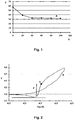
Figure 1 shows the percentage Cr/ (Cr + Fe) over the depth from the surface of the stainless steel fibers for an example of the invention. -
Figure 2 shows a CPP curve of an example of the invention. - A first example of a heat resistant separation material according to the invention is a weft knitted mould covering fabric consisting out of stainless steel fibers of diameter 12 µm out of stainless steel alloy 316L, spun into yarns of Nm 11/2. The fabric has a specific weight of 950 g/m2.
- A second example of a heat resistant separation material according to the invention is a circular weft knitted tubular sleeve of
diameter 60 mm (in unstretched state) consisting out of stainless steel fibers of diameter 12 µm out of stainless steel alloy 347, spun into yarns of Nm 11/2. The sleeve has a specific weight of 136 g/m2. - The fabrics according to the invention were treated in an aqueous solution of 30 % by volume of nitric acid during a time period of one hour at a temperature of 50°C. Afterwards, the fabric was neutralized, rinsed and dried.
-
Figure 1 shows the percentage of atomic Cr over the sum of the atomic percentages of Cr and Fe over the depth from the surface of the stainless steel fibers for an example of the invention (curve A). The test results have been obtained using XPS. In horizontal axis (X) the depth in nanometer from the stainless steel fiber surface (which obviously coincides with the surface of the oxide layer) is shown. The Y-axis shows the atomic percentage of Cr divided by the sum of the atomic percentages of Cr and Fe, and multiplied with 100, to express the result as a percentage. Curve A shows the result as a function of the depth from the surface of the stainless steel fiber. In the sample tested and shown infigure 1 , at the surface of the stainless steel fiber (which is also the surface of the oxide skin on the stainless steel fiber) the atomic percentage of Cr is 14.5%, while the atomic percentage of Fe is 10.9%, resulting in Cr/(Cr + Fe)*100 of 57.08%. -
Figure 2 shows a cyclic potentiodynamic polarization (CPP) curve for an example of heat resistant separation fabric according to the invention. The vertical axis V indicates the potential (in Volt) relative to an SHE-electrode (Standard Hydrogen Electrode). The horizontal axis log (A) indicates the logarithm of the measured electrical current in Ampere. E represents the measured CPP curve of the sample. F is the potential range of the current plateau (measured from inflection point to inflection point), and H is the breakdown potential. In the example shown (figure 2 ) the potential range of the current plateau is 0.19 V and the breakdown potential is 0.56 V. - Another example of the invention, made with a treatment time of two hours in the acid solution, showed a potential range of the current plateau of 0.20 V and a breakdown potential of 0.61 V.
- Trials in car glass production with the exemplary sleeves as roller covering have shown an important improvement of quality of the car glass (lites) produced when starting up with new sleeves. With prior art sleeves, quality of the first lites was not good, lites had to be thrown away frequently because of markings and/or imprints in the lites or because of an unwanted contamination of the lites. The contamination sometimes appeared as a haze on the glass in which the imprint of the tool covering fabric could be distinguished. The contamination could sometimes be removed by means of brushing or polishing, however, this is an extra step that requires extra labour and cost. The sleeves according to the invention did not show the contamination on the lites and provided improved quality of lites at start-up.
- Furthermore, the slippage problem between covered rollers and glass panels that was observed with prior art sleeves did not occur when using sleeves according to the invention as roller covering.
Claims (9)
- Heat resistant separation fabric comprising stainless steel fibers,- wherein said stainless steel fibers are made out of an alloy comprising more than 12 % by weight of chromium;- wherein said stainless steel fibers comprise an oxide skin;characterised in that the atomic percentage of Cr at 5 nm depth of said oxide skin divided by the sum of the atomic percentages of Cr and Fe at 5 nm depth of said oxide skin, and multiplied with 100, is higher than 30%.
- Heat resistant separation fabric as in claim 1, wherein in said oxide skin the atomic percentage of Cr divided by the sum of the atomic percentages of Cr and Fe, and multiplied with 100, is higher than 30% from the surface till minimum at a depth of 25 nm.
- Heat resistant separation fabric as in claims 1 or 2, wherein said oxide skin covers the complete surface of said stainless steel fibers.
- Heat resistant separation fabric as in any of the preceding claims, wherein the potential range of the current plateau as measured in cyclic potentiodynamic polarization is at least 0.18V.
- Heat resistant separation fabric as in any of the preceding claims, wherein the breakdown potential as measured in cyclic potentiodynamic polarization is, compared to the Standard Hydrogen Electrode, higher than 0.55 V.
- Heat resistant separation fabric as in any of the preceding claims, wherein said heat resistant separation fabric consists out of stainless steel fibers.
- Heat resistant separation fabric as in any of the preceding claims, wherein the heat resistant separation fabric is a sleeve.
- Heat resistant separation fabric as in claims 1 - 6, wherein the heat resistant separation fabric is a press mould covering or a quench ring covering.
- Use of a heat resistant separation material as in claims 1 - 8, as covering of tooling that comes in contact with hot glass products in glass products production, in order to improve the quality of the glass products when starting glass products production with new covering.
Priority Applications (2)
| Application Number | Priority Date | Filing Date | Title |
|---|---|---|---|
| PL14725069T PL3003999T3 (en) | 2013-05-29 | 2014-05-13 | Heat resistant separation fabric |
| EP14725069.0A EP3003999B1 (en) | 2013-05-29 | 2014-05-13 | Heat resistant separation fabric |
Applications Claiming Priority (3)
| Application Number | Priority Date | Filing Date | Title |
|---|---|---|---|
| EP13169688 | 2013-05-29 | ||
| PCT/EP2014/059709 WO2014191193A1 (en) | 2013-05-29 | 2014-05-13 | Heat resistant separation fabric |
| EP14725069.0A EP3003999B1 (en) | 2013-05-29 | 2014-05-13 | Heat resistant separation fabric |
Publications (2)
| Publication Number | Publication Date |
|---|---|
| EP3003999A1 EP3003999A1 (en) | 2016-04-13 |
| EP3003999B1 true EP3003999B1 (en) | 2017-03-01 |
Family
ID=48577508
Family Applications (1)
| Application Number | Title | Priority Date | Filing Date |
|---|---|---|---|
| EP14725069.0A Active EP3003999B1 (en) | 2013-05-29 | 2014-05-13 | Heat resistant separation fabric |
Country Status (6)
| Country | Link |
|---|---|
| US (1) | US20160083285A1 (en) |
| EP (1) | EP3003999B1 (en) |
| CN (1) | CN105246845B (en) |
| HU (1) | HUE034243T2 (en) |
| PL (1) | PL3003999T3 (en) |
| WO (1) | WO2014191193A1 (en) |
Families Citing this family (16)
| Publication number | Priority date | Publication date | Assignee | Title |
|---|---|---|---|---|
| US11669090B2 (en) | 2014-05-20 | 2023-06-06 | State Farm Mutual Automobile Insurance Company | Autonomous vehicle operation feature monitoring and evaluation of effectiveness |
| US10599155B1 (en) | 2014-05-20 | 2020-03-24 | State Farm Mutual Automobile Insurance Company | Autonomous vehicle operation feature monitoring and evaluation of effectiveness |
| US10185997B1 (en) | 2014-05-20 | 2019-01-22 | State Farm Mutual Automobile Insurance Company | Accident fault determination for autonomous vehicles |
| US9972054B1 (en) | 2014-05-20 | 2018-05-15 | State Farm Mutual Automobile Insurance Company | Accident fault determination for autonomous vehicles |
| US10373259B1 (en) | 2014-05-20 | 2019-08-06 | State Farm Mutual Automobile Insurance Company | Fully autonomous vehicle insurance pricing |
| US10540723B1 (en) | 2014-07-21 | 2020-01-21 | State Farm Mutual Automobile Insurance Company | Methods of providing insurance savings based upon telematics and usage-based insurance |
| US10266180B1 (en) | 2014-11-13 | 2019-04-23 | State Farm Mutual Automobile Insurance Company | Autonomous vehicle control assessment and selection |
| US9870649B1 (en) | 2015-08-28 | 2018-01-16 | State Farm Mutual Automobile Insurance Company | Shared vehicle usage, monitoring and feedback |
| US11119477B1 (en) | 2016-01-22 | 2021-09-14 | State Farm Mutual Automobile Insurance Company | Anomalous condition detection and response for autonomous vehicles |
| US10134278B1 (en) | 2016-01-22 | 2018-11-20 | State Farm Mutual Automobile Insurance Company | Autonomous vehicle application |
| US10324463B1 (en) | 2016-01-22 | 2019-06-18 | State Farm Mutual Automobile Insurance Company | Autonomous vehicle operation adjustment based upon route |
| US11441916B1 (en) | 2016-01-22 | 2022-09-13 | State Farm Mutual Automobile Insurance Company | Autonomous vehicle trip routing |
| US11719545B2 (en) | 2016-01-22 | 2023-08-08 | Hyundai Motor Company | Autonomous vehicle component damage and salvage assessment |
| US11242051B1 (en) | 2016-01-22 | 2022-02-08 | State Farm Mutual Automobile Insurance Company | Autonomous vehicle action communications |
| US10395332B1 (en) | 2016-01-22 | 2019-08-27 | State Farm Mutual Automobile Insurance Company | Coordinated autonomous vehicle automatic area scanning |
| ES2909727T3 (en) | 2017-11-17 | 2022-05-10 | Bekaert Sa Nv | Heat resistant separation cloth |
Family Cites Families (10)
| Publication number | Priority date | Publication date | Assignee | Title |
|---|---|---|---|---|
| FR2673424B1 (en) * | 1991-03-01 | 1993-12-03 | Saint Gobain Vitrage Internal | COATING FOR BOMBING FORMS. |
| US5607520A (en) * | 1995-08-18 | 1997-03-04 | Northrop Grumman Corporation | Reel-to-reel passivation of stainless steel wire |
| DE69731788T2 (en) * | 1996-05-29 | 2005-12-08 | Sumitomo Metal Industries, Ltd. | Use of a stainless steel in or containing water with added ozone |
| US5858200A (en) * | 1996-05-30 | 1999-01-12 | Bridgestone Metalpha Corporation | Method of and apparatus for manufacturing metallic fiber and the twine of metallic fibers, and method of coloring metallic fiber and the twine of metallic fibers |
| BE1012976A3 (en) | 1998-03-18 | 2001-07-03 | Bekaert Sa Nv | HETEROGENEOUS THIN KNIT FABRIC COMPREHENSIVE metal fibers. |
| DE69921186T2 (en) | 1999-01-08 | 2005-11-10 | N.V. Bekaert S.A. | STRICKWARE OF STEEL FIBERS WITH INCREASED NUMBER OF MESH |
| DK1169272T3 (en) | 1999-04-09 | 2002-10-14 | Bekaert Sa Nv | Heat-resistant covering material |
| JP4301664B2 (en) | 1999-12-03 | 2009-07-22 | 日本精線株式会社 | Heat-resistant knitted fabric for buffer material for glass molds |
| HUE039285T2 (en) | 2010-03-26 | 2018-12-28 | Bekaert Sa Nv | Hybrid sleeve with glass or ceramic fibres and metal fibres |
| BE1020217A3 (en) * | 2011-09-09 | 2013-06-04 | Bekaert Sa Nv | FABRICS FOR THE PRODUCTION OF MIRRORS. |
-
2014
- 2014-05-13 CN CN201480029969.XA patent/CN105246845B/en active Active
- 2014-05-13 PL PL14725069T patent/PL3003999T3/en unknown
- 2014-05-13 WO PCT/EP2014/059709 patent/WO2014191193A1/en active Application Filing
- 2014-05-13 US US14/785,256 patent/US20160083285A1/en not_active Abandoned
- 2014-05-13 EP EP14725069.0A patent/EP3003999B1/en active Active
- 2014-05-13 HU HUE14725069A patent/HUE034243T2/en unknown
Non-Patent Citations (1)
| Title |
|---|
| None * |
Also Published As
| Publication number | Publication date |
|---|---|
| EP3003999A1 (en) | 2016-04-13 |
| PL3003999T3 (en) | 2017-08-31 |
| WO2014191193A1 (en) | 2014-12-04 |
| CN105246845B (en) | 2018-03-16 |
| CN105246845A (en) | 2016-01-13 |
| US20160083285A1 (en) | 2016-03-24 |
| HUE034243T2 (en) | 2018-02-28 |
Similar Documents
| Publication | Publication Date | Title |
|---|---|---|
| EP3003999B1 (en) | Heat resistant separation fabric | |
| JP4719320B2 (en) | High strength extra fine steel wire and method for producing the same | |
| Ryl et al. | Study on surface termination of boron-doped diamond electrodes under anodic polarization in H2SO4 by means of dynamic impedance technique | |
| CN112272717A (en) | Apparatus, system, and method for producing multiple articles with nanolaminate coating using rotation | |
| Sinha et al. | Textile-based electrochemical sensors and their applications | |
| KR101545416B1 (en) | Method for producing surface-treated metallic material | |
| Bennett et al. | Investigating the viability of electrodeposited vanadium pentoxide as a suitable electrode material for in vivo amperometric hydrogen sulfide detection | |
| Crassous et al. | Study of the fluorination of carbon anode in molten KF-2HF by XPS and NMR investigations | |
| JP5202998B2 (en) | Chuck device, tensile test device, and manufacturing method of chuck device | |
| CN104562631A (en) | Anodic oxidation surface treatment method of carbon fibers | |
| JP5081570B2 (en) | Titanium material and titanium material manufacturing method | |
| JP2009114557A (en) | Uniformly surface-treated carbon fiber and method for producing the same | |
| Liu et al. | Electrodeposition of dendritic silver nanostructures and their application as hydrogen peroxide sensor | |
| JP5625288B2 (en) | Corrosion-resistant wear-resistant member and manufacturing method thereof | |
| WO2015139731A1 (en) | Method for delamination of ceramic hard material layers from steel and cemented carbide substrates | |
| JP2008240140A (en) | Steel wire for reinforcing rubber product excellent in corrosion fatigue resistance and its manufacturing method | |
| Recco et al. | A new strategy for detecting dopamine in human serum using polymer brushes reinforced with carbon nanotubes | |
| Akbarov et al. | Development of electroconductive polyacrylonitrile fibers through chemical metallization and galvanisation | |
| Hadi et al. | Filamentous pyrolytic carbon film and its electroanalytical properties | |
| EP3710625B1 (en) | Heat resistant separation fabric | |
| CN104321636B (en) | For the analysis method for the cleannes level for quantifying parts surface | |
| Asai et al. | Fabrication of an all-diamond microelectrode using a chromium mask | |
| WO2010070742A1 (en) | Titanium material and method for producing titanium material | |
| JP2010209405A (en) | Stainless steel having excellent surface electric conductivity, and method for manufacturing the same | |
| Wang et al. | Reduced graphene oxide cotton fabric based on copper nanowires for flexible non-enzyme glucose sensor |
Legal Events
| Date | Code | Title | Description |
|---|---|---|---|
| PUAI | Public reference made under article 153(3) epc to a published international application that has entered the european phase |
Free format text: ORIGINAL CODE: 0009012 |
|
| 17P | Request for examination filed |
Effective date: 20150930 |
|
| AK | Designated contracting states |
Kind code of ref document: A1 Designated state(s): AL AT BE BG CH CY CZ DE DK EE ES FI FR GB GR HR HU IE IS IT LI LT LU LV MC MK MT NL NO PL PT RO RS SE SI SK SM TR |
|
| AX | Request for extension of the european patent |
Extension state: BA ME |
|
| DAX | Request for extension of the european patent (deleted) | ||
| GRAP | Despatch of communication of intention to grant a patent |
Free format text: ORIGINAL CODE: EPIDOSNIGR1 |
|
| INTG | Intention to grant announced |
Effective date: 20161011 |
|
| GRAS | Grant fee paid |
Free format text: ORIGINAL CODE: EPIDOSNIGR3 |
|
| GRAA | (expected) grant |
Free format text: ORIGINAL CODE: 0009210 |
|
| AK | Designated contracting states |
Kind code of ref document: B1 Designated state(s): AL AT BE BG CH CY CZ DE DK EE ES FI FR GB GR HR HU IE IS IT LI LT LU LV MC MK MT NL NO PL PT RO RS SE SI SK SM TR |
|
| REG | Reference to a national code |
Ref country code: GB Ref legal event code: FG4D |
|
| REG | Reference to a national code |
Ref country code: CH Ref legal event code: EP Ref country code: AT Ref legal event code: REF Ref document number: 871065 Country of ref document: AT Kind code of ref document: T Effective date: 20170315 |
|
| REG | Reference to a national code |
Ref country code: IE Ref legal event code: FG4D |
|
| REG | Reference to a national code |
Ref country code: DE Ref legal event code: R096 Ref document number: 602014007173 Country of ref document: DE |
|
| REG | Reference to a national code |
Ref country code: NL Ref legal event code: MP Effective date: 20170301 |
|
| REG | Reference to a national code |
Ref country code: LT Ref legal event code: MG4D |
|
| REG | Reference to a national code |
Ref country code: AT Ref legal event code: MK05 Ref document number: 871065 Country of ref document: AT Kind code of ref document: T Effective date: 20170301 |
|
| PG25 | Lapsed in a contracting state [announced via postgrant information from national office to epo] |
Ref country code: FI Free format text: LAPSE BECAUSE OF FAILURE TO SUBMIT A TRANSLATION OF THE DESCRIPTION OR TO PAY THE FEE WITHIN THE PRESCRIBED TIME-LIMIT Effective date: 20170301 Ref country code: LT Free format text: LAPSE BECAUSE OF FAILURE TO SUBMIT A TRANSLATION OF THE DESCRIPTION OR TO PAY THE FEE WITHIN THE PRESCRIBED TIME-LIMIT Effective date: 20170301 Ref country code: NO Free format text: LAPSE BECAUSE OF FAILURE TO SUBMIT A TRANSLATION OF THE DESCRIPTION OR TO PAY THE FEE WITHIN THE PRESCRIBED TIME-LIMIT Effective date: 20170601 Ref country code: HR Free format text: LAPSE BECAUSE OF FAILURE TO SUBMIT A TRANSLATION OF THE DESCRIPTION OR TO PAY THE FEE WITHIN THE PRESCRIBED TIME-LIMIT Effective date: 20170301 Ref country code: GR Free format text: LAPSE BECAUSE OF FAILURE TO SUBMIT A TRANSLATION OF THE DESCRIPTION OR TO PAY THE FEE WITHIN THE PRESCRIBED TIME-LIMIT Effective date: 20170602 |
|
| PG25 | Lapsed in a contracting state [announced via postgrant information from national office to epo] |
Ref country code: ES Free format text: LAPSE BECAUSE OF FAILURE TO SUBMIT A TRANSLATION OF THE DESCRIPTION OR TO PAY THE FEE WITHIN THE PRESCRIBED TIME-LIMIT Effective date: 20170301 Ref country code: BG Free format text: LAPSE BECAUSE OF FAILURE TO SUBMIT A TRANSLATION OF THE DESCRIPTION OR TO PAY THE FEE WITHIN THE PRESCRIBED TIME-LIMIT Effective date: 20170601 Ref country code: SE Free format text: LAPSE BECAUSE OF FAILURE TO SUBMIT A TRANSLATION OF THE DESCRIPTION OR TO PAY THE FEE WITHIN THE PRESCRIBED TIME-LIMIT Effective date: 20170301 Ref country code: AT Free format text: LAPSE BECAUSE OF FAILURE TO SUBMIT A TRANSLATION OF THE DESCRIPTION OR TO PAY THE FEE WITHIN THE PRESCRIBED TIME-LIMIT Effective date: 20170301 Ref country code: RS Free format text: LAPSE BECAUSE OF FAILURE TO SUBMIT A TRANSLATION OF THE DESCRIPTION OR TO PAY THE FEE WITHIN THE PRESCRIBED TIME-LIMIT Effective date: 20170301 Ref country code: LV Free format text: LAPSE BECAUSE OF FAILURE TO SUBMIT A TRANSLATION OF THE DESCRIPTION OR TO PAY THE FEE WITHIN THE PRESCRIBED TIME-LIMIT Effective date: 20170301 |
|
| PG25 | Lapsed in a contracting state [announced via postgrant information from national office to epo] |
Ref country code: NL Free format text: LAPSE BECAUSE OF FAILURE TO SUBMIT A TRANSLATION OF THE DESCRIPTION OR TO PAY THE FEE WITHIN THE PRESCRIBED TIME-LIMIT Effective date: 20170301 |
|
| PG25 | Lapsed in a contracting state [announced via postgrant information from national office to epo] |
Ref country code: SK Free format text: LAPSE BECAUSE OF FAILURE TO SUBMIT A TRANSLATION OF THE DESCRIPTION OR TO PAY THE FEE WITHIN THE PRESCRIBED TIME-LIMIT Effective date: 20170301 Ref country code: RO Free format text: LAPSE BECAUSE OF FAILURE TO SUBMIT A TRANSLATION OF THE DESCRIPTION OR TO PAY THE FEE WITHIN THE PRESCRIBED TIME-LIMIT Effective date: 20170301 Ref country code: CZ Free format text: LAPSE BECAUSE OF FAILURE TO SUBMIT A TRANSLATION OF THE DESCRIPTION OR TO PAY THE FEE WITHIN THE PRESCRIBED TIME-LIMIT Effective date: 20170301 Ref country code: EE Free format text: LAPSE BECAUSE OF FAILURE TO SUBMIT A TRANSLATION OF THE DESCRIPTION OR TO PAY THE FEE WITHIN THE PRESCRIBED TIME-LIMIT Effective date: 20170301 |
|
| PG25 | Lapsed in a contracting state [announced via postgrant information from national office to epo] |
Ref country code: PT Free format text: LAPSE BECAUSE OF FAILURE TO SUBMIT A TRANSLATION OF THE DESCRIPTION OR TO PAY THE FEE WITHIN THE PRESCRIBED TIME-LIMIT Effective date: 20170703 Ref country code: IS Free format text: LAPSE BECAUSE OF FAILURE TO SUBMIT A TRANSLATION OF THE DESCRIPTION OR TO PAY THE FEE WITHIN THE PRESCRIBED TIME-LIMIT Effective date: 20170701 Ref country code: SM Free format text: LAPSE BECAUSE OF FAILURE TO SUBMIT A TRANSLATION OF THE DESCRIPTION OR TO PAY THE FEE WITHIN THE PRESCRIBED TIME-LIMIT Effective date: 20170301 |
|
| REG | Reference to a national code |
Ref country code: DE Ref legal event code: R119 Ref document number: 602014007173 Country of ref document: DE |
|
| REG | Reference to a national code |
Ref country code: CH Ref legal event code: PL |
|
| PLBE | No opposition filed within time limit |
Free format text: ORIGINAL CODE: 0009261 |
|
| STAA | Information on the status of an ep patent application or granted ep patent |
Free format text: STATUS: NO OPPOSITION FILED WITHIN TIME LIMIT |
|
| PG25 | Lapsed in a contracting state [announced via postgrant information from national office to epo] |
Ref country code: DK Free format text: LAPSE BECAUSE OF FAILURE TO SUBMIT A TRANSLATION OF THE DESCRIPTION OR TO PAY THE FEE WITHIN THE PRESCRIBED TIME-LIMIT Effective date: 20170301 Ref country code: MC Free format text: LAPSE BECAUSE OF FAILURE TO SUBMIT A TRANSLATION OF THE DESCRIPTION OR TO PAY THE FEE WITHIN THE PRESCRIBED TIME-LIMIT Effective date: 20170301 |
|
| 26N | No opposition filed |
Effective date: 20171204 |
|
| REG | Reference to a national code |
Ref country code: IE Ref legal event code: MM4A |
|
| PG25 | Lapsed in a contracting state [announced via postgrant information from national office to epo] |
Ref country code: SI Free format text: LAPSE BECAUSE OF FAILURE TO SUBMIT A TRANSLATION OF THE DESCRIPTION OR TO PAY THE FEE WITHIN THE PRESCRIBED TIME-LIMIT Effective date: 20170301 Ref country code: LI Free format text: LAPSE BECAUSE OF NON-PAYMENT OF DUE FEES Effective date: 20170531 Ref country code: CH Free format text: LAPSE BECAUSE OF NON-PAYMENT OF DUE FEES Effective date: 20170531 |
|
| REG | Reference to a national code |
Ref country code: HU Ref legal event code: AG4A Ref document number: E034243 Country of ref document: HU |
|
| REG | Reference to a national code |
Ref country code: FR Ref legal event code: ST Effective date: 20180131 |
|
| REG | Reference to a national code |
Ref country code: BE Ref legal event code: MM Effective date: 20170531 |
|
| PG25 | Lapsed in a contracting state [announced via postgrant information from national office to epo] |
Ref country code: IE Free format text: LAPSE BECAUSE OF NON-PAYMENT OF DUE FEES Effective date: 20170513 Ref country code: DE Free format text: LAPSE BECAUSE OF NON-PAYMENT OF DUE FEES Effective date: 20171201 |
|
| PG25 | Lapsed in a contracting state [announced via postgrant information from national office to epo] |
Ref country code: FR Free format text: LAPSE BECAUSE OF NON-PAYMENT OF DUE FEES Effective date: 20170531 |
|
| PG25 | Lapsed in a contracting state [announced via postgrant information from national office to epo] |
Ref country code: BE Free format text: LAPSE BECAUSE OF NON-PAYMENT OF DUE FEES Effective date: 20170531 |
|
| PG25 | Lapsed in a contracting state [announced via postgrant information from national office to epo] |
Ref country code: MT Free format text: LAPSE BECAUSE OF NON-PAYMENT OF DUE FEES Effective date: 20170513 |
|
| GBPC | Gb: european patent ceased through non-payment of renewal fee |
Effective date: 20180513 |
|
| PG25 | Lapsed in a contracting state [announced via postgrant information from national office to epo] |
Ref country code: GB Free format text: LAPSE BECAUSE OF NON-PAYMENT OF DUE FEES Effective date: 20180513 |
|
| PG25 | Lapsed in a contracting state [announced via postgrant information from national office to epo] |
Ref country code: CY Free format text: LAPSE BECAUSE OF FAILURE TO SUBMIT A TRANSLATION OF THE DESCRIPTION OR TO PAY THE FEE WITHIN THE PRESCRIBED TIME-LIMIT Effective date: 20170301 |
|
| PG25 | Lapsed in a contracting state [announced via postgrant information from national office to epo] |
Ref country code: MK Free format text: LAPSE BECAUSE OF FAILURE TO SUBMIT A TRANSLATION OF THE DESCRIPTION OR TO PAY THE FEE WITHIN THE PRESCRIBED TIME-LIMIT Effective date: 20170301 |
|
| PG25 | Lapsed in a contracting state [announced via postgrant information from national office to epo] |
Ref country code: TR Free format text: LAPSE BECAUSE OF FAILURE TO SUBMIT A TRANSLATION OF THE DESCRIPTION OR TO PAY THE FEE WITHIN THE PRESCRIBED TIME-LIMIT Effective date: 20170301 |
|
| PG25 | Lapsed in a contracting state [announced via postgrant information from national office to epo] |
Ref country code: AL Free format text: LAPSE BECAUSE OF FAILURE TO SUBMIT A TRANSLATION OF THE DESCRIPTION OR TO PAY THE FEE WITHIN THE PRESCRIBED TIME-LIMIT Effective date: 20170301 |
|
| PGFP | Annual fee paid to national office [announced via postgrant information from national office to epo] |
Ref country code: LU Payment date: 20230519 Year of fee payment: 10 |
|
| P01 | Opt-out of the competence of the unified patent court (upc) registered |
Effective date: 20230619 |
|
| PGFP | Annual fee paid to national office [announced via postgrant information from national office to epo] |
Ref country code: IT Payment date: 20230526 Year of fee payment: 10 |
|
| PGFP | Annual fee paid to national office [announced via postgrant information from national office to epo] |
Ref country code: PL Payment date: 20230507 Year of fee payment: 10 Ref country code: HU Payment date: 20230523 Year of fee payment: 10 |