EP3003185B1 - Instrument for inserting an interspinous process implant - Google Patents
Instrument for inserting an interspinous process implant Download PDFInfo
- Publication number
- EP3003185B1 EP3003185B1 EP14804610.5A EP14804610A EP3003185B1 EP 3003185 B1 EP3003185 B1 EP 3003185B1 EP 14804610 A EP14804610 A EP 14804610A EP 3003185 B1 EP3003185 B1 EP 3003185B1
- Authority
- EP
- European Patent Office
- Prior art keywords
- implant
- plunger
- insertion instrument
- main body
- spike cap
- Prior art date
- Legal status (The legal status is an assumption and is not a legal conclusion. Google has not performed a legal analysis and makes no representation as to the accuracy of the status listed.)
- Active
Links
Images


Classifications
-
- A—HUMAN NECESSITIES
- A61—MEDICAL OR VETERINARY SCIENCE; HYGIENE
- A61B—DIAGNOSIS; SURGERY; IDENTIFICATION
- A61B17/00—Surgical instruments, devices or methods, e.g. tourniquets
- A61B17/56—Surgical instruments or methods for treatment of bones or joints; Devices specially adapted therefor
- A61B17/58—Surgical instruments or methods for treatment of bones or joints; Devices specially adapted therefor for osteosynthesis, e.g. bone plates, screws, setting implements or the like
- A61B17/68—Internal fixation devices, including fasteners and spinal fixators, even if a part thereof projects from the skin
- A61B17/70—Spinal positioners or stabilisers ; Bone stabilisers comprising fluid filler in an implant
- A61B17/7062—Devices acting on, attached to, or simulating the effect of, vertebral processes, vertebral facets or ribs ; Tools for such devices
- A61B17/7065—Devices with changeable shape, e.g. collapsible or having retractable arms to aid implantation; Tools therefor
-
- A—HUMAN NECESSITIES
- A61—MEDICAL OR VETERINARY SCIENCE; HYGIENE
- A61B—DIAGNOSIS; SURGERY; IDENTIFICATION
- A61B17/00—Surgical instruments, devices or methods, e.g. tourniquets
- A61B17/56—Surgical instruments or methods for treatment of bones or joints; Devices specially adapted therefor
- A61B17/58—Surgical instruments or methods for treatment of bones or joints; Devices specially adapted therefor for osteosynthesis, e.g. bone plates, screws, setting implements or the like
- A61B17/68—Internal fixation devices, including fasteners and spinal fixators, even if a part thereof projects from the skin
- A61B17/70—Spinal positioners or stabilisers ; Bone stabilisers comprising fluid filler in an implant
- A61B17/7062—Devices acting on, attached to, or simulating the effect of, vertebral processes, vertebral facets or ribs ; Tools for such devices
-
- A—HUMAN NECESSITIES
- A61—MEDICAL OR VETERINARY SCIENCE; HYGIENE
- A61B—DIAGNOSIS; SURGERY; IDENTIFICATION
- A61B17/00—Surgical instruments, devices or methods, e.g. tourniquets
- A61B17/56—Surgical instruments or methods for treatment of bones or joints; Devices specially adapted therefor
- A61B17/58—Surgical instruments or methods for treatment of bones or joints; Devices specially adapted therefor for osteosynthesis, e.g. bone plates, screws, setting implements or the like
- A61B17/68—Internal fixation devices, including fasteners and spinal fixators, even if a part thereof projects from the skin
- A61B17/70—Spinal positioners or stabilisers ; Bone stabilisers comprising fluid filler in an implant
- A61B17/7074—Tools specially adapted for spinal fixation operations other than for bone removal or filler handling
-
- A—HUMAN NECESSITIES
- A61—MEDICAL OR VETERINARY SCIENCE; HYGIENE
- A61B—DIAGNOSIS; SURGERY; IDENTIFICATION
- A61B17/00—Surgical instruments, devices or methods, e.g. tourniquets
- A61B17/56—Surgical instruments or methods for treatment of bones or joints; Devices specially adapted therefor
- A61B17/58—Surgical instruments or methods for treatment of bones or joints; Devices specially adapted therefor for osteosynthesis, e.g. bone plates, screws, setting implements or the like
- A61B17/68—Internal fixation devices, including fasteners and spinal fixators, even if a part thereof projects from the skin
- A61B17/84—Fasteners therefor or fasteners being internal fixation devices
- A61B17/844—Fasteners therefor or fasteners being internal fixation devices with expandable anchors or anchors having movable parts
-
- A—HUMAN NECESSITIES
- A61—MEDICAL OR VETERINARY SCIENCE; HYGIENE
- A61B—DIAGNOSIS; SURGERY; IDENTIFICATION
- A61B17/00—Surgical instruments, devices or methods, e.g. tourniquets
- A61B17/56—Surgical instruments or methods for treatment of bones or joints; Devices specially adapted therefor
- A61B17/58—Surgical instruments or methods for treatment of bones or joints; Devices specially adapted therefor for osteosynthesis, e.g. bone plates, screws, setting implements or the like
- A61B17/88—Osteosynthesis instruments; Methods or means for implanting or extracting internal or external fixation devices
- A61B17/8875—Screwdrivers, spanners or wrenches
- A61B17/8877—Screwdrivers, spanners or wrenches characterised by the cross-section of the driver bit
- A61B17/8883—Screwdrivers, spanners or wrenches characterised by the cross-section of the driver bit the driver bit acting on the periphery of the screw head
-
- A—HUMAN NECESSITIES
- A61—MEDICAL OR VETERINARY SCIENCE; HYGIENE
- A61B—DIAGNOSIS; SURGERY; IDENTIFICATION
- A61B17/00—Surgical instruments, devices or methods, e.g. tourniquets
- A61B17/56—Surgical instruments or methods for treatment of bones or joints; Devices specially adapted therefor
- A61B17/58—Surgical instruments or methods for treatment of bones or joints; Devices specially adapted therefor for osteosynthesis, e.g. bone plates, screws, setting implements or the like
- A61B17/88—Osteosynthesis instruments; Methods or means for implanting or extracting internal or external fixation devices
- A61B17/8875—Screwdrivers, spanners or wrenches
- A61B17/8886—Screwdrivers, spanners or wrenches holding the screw head
- A61B17/8888—Screwdrivers, spanners or wrenches holding the screw head at its central region
-
- A—HUMAN NECESSITIES
- A61—MEDICAL OR VETERINARY SCIENCE; HYGIENE
- A61B—DIAGNOSIS; SURGERY; IDENTIFICATION
- A61B17/00—Surgical instruments, devices or methods, e.g. tourniquets
- A61B17/56—Surgical instruments or methods for treatment of bones or joints; Devices specially adapted therefor
- A61B17/58—Surgical instruments or methods for treatment of bones or joints; Devices specially adapted therefor for osteosynthesis, e.g. bone plates, screws, setting implements or the like
- A61B17/88—Osteosynthesis instruments; Methods or means for implanting or extracting internal or external fixation devices
- A61B17/8875—Screwdrivers, spanners or wrenches
- A61B17/8886—Screwdrivers, spanners or wrenches holding the screw head
- A61B17/8891—Screwdrivers, spanners or wrenches holding the screw head at its periphery
-
- A—HUMAN NECESSITIES
- A61—MEDICAL OR VETERINARY SCIENCE; HYGIENE
- A61B—DIAGNOSIS; SURGERY; IDENTIFICATION
- A61B17/00—Surgical instruments, devices or methods, e.g. tourniquets
- A61B2017/00526—Methods of manufacturing
Definitions
- the spine consists of a column of twenty-four vertebrae that extend from the skull to the hips. Discs of soft tissue are disposed between adjacent vertebrae. The vertebrae provide support for the head and body, while the discs act as cushions. In addition, the spine encloses and protects the spinal cord, defining a bony channel around the spinal cord, called the spinal canal. There is normally a space between the spinal cord and the borders of the spinal canal so that the spinal cord and the nerves associated therewith are not pinched.
- Non-surgical treatments for spinal stenosis include non-steroidal anti-inflammatory drugs to reduce the swelling and pain, and corticosteroid injections to reduce swelling and treat acute pain. While some patients may experience relief from symptoms of spinal stenosis with such treatments, many do not, and thus turn to surgical treatment.
- Some surgical procedures for treating spinal stenosis are decompressive laminectomy and interspinous process decompression (IPD).
- a well-known implant used for performing IPD surgery is the X-STOP® device, which is described in U.S. Patent No. 6,419,676 .
- Another interspinous process implant placed in a minimally invasive surgical procedure is disclosed in U.S. Patent Application Publication 2008/0243250 .
- Still another interspinous process implant placed in a minimally invasive surgical procedure is disclosed in U.S. Patent Application Publication 2010/0234889 .
- One aspect of effective insertion of these implants is to provide a low profile instrument for deploying the implant. Often, the insertion instrument has several moving parts. Because of the cost of the insertion instruments, the instruments are re-used many times.
- US 2010/0057130 A1 discloses a conical interspinous apparatus including a distractor comprising an insertion portion and a central engagement groove, the insertion portion having a conical shape which tapers to a tip and is adapted to enable passage of the distractor between two spinous processes of vertebrae, and the central engagement groove is adapted to secure the distractor between the two spinous processes such that the two spinous processes rest in the central engagement groove.
- the conical interspinous apparatus includes a stabilizer which is adapted to be deployed from within the distractor to secure the two spinous processes within the central engagement groove and an insertion driver detachably coupled to a rear portion of the distractor.
- a guide wire having a pointed tip, aids in the insertion of the distractor between the two spinous processes and is configured to guide the insertion of the distractor.
- CA 2 751 750 A1 discloses an interspinous process implant having deployable engagement arms.
- the implant includes an elongated body portion dimensioned and configured for percutaneous introduction into a target interspinous process space, at which interspinous distraction and/or spinal fusion are desired.
- the body portion can include a threaded outer surface, or alternatively a smooth surface.
- the body portion can include one or more interior cavities, and can include deployable engagement members adapted and configured to move in tandem between a stowed position retracted within the interior cavity of the body portion and a deployed position extended from the interior cavity of the body for engaging adjacent spinous processes.
- An internal drive assembly for selectively moving the engagement members from the stowed position to the deployed position can be provided, as can a elements for locking the engagement members in a deployed position.
- WO 2010/025408 A2 discloses a bone-derived interspinous spacer for implantation into an interspinous space located between spinous process of adjacent vertebrae.
- the spacer preferably includes a body, a core and a plurality of dep lovable retainers.
- the body may be operatively associated with the plurality of deployable retainers.
- the plurality of retainers is deployed so that they prevent migration of the spacer.
- the core is preferably sized and configured to be inserted and/or moved into operatively engagement with the body to deploy the plurality of retainers.
- the subject technology is directed to an insertion device for a spinal implant, wherein the spinal implant includes: a) an elongated body to function as a spacer placed in a target interspinous process space between two adjacent spinous processes, wherein the body defines an interior and a proximal internal recess for access to the interior, the proximal internal recess forming a transverse groove; b) a distal anchor that is at least partially threaded and has opposing radially deployable blades mounted for rotation about a pin transversely mounted in the interior; c) a proximal anchor including a spike cap mounted to slide along the body and a drive nut mounted for longitudinal movement along the body between a first position spaced apart from the distal anchor and a second position relatively closer to the distal anchor to thereby compress the two adjacent spinous processes between the spike cap and the distal anchor; and d) an actuation plunger slidably inside the interior for moving the blades from a stowed/insertion position to
- the insertion device includes an elongated main body having a distal locking portion for coupling to the implant and a proximal handle portion.
- the main body defines a central passage and the distal locking portion has outer ridges.
- the at least one slot allows at least one of the outer ridges to flex radially inward.
- a plunger slides in the central passage for movement between an unlocked position for mounting the implant on the distal locking portion, a locked position within the slot for locking the implant on the distal locking portion, and an insertion instrument deployed position for deploying the actuation plunger to move the blades from the stowed position to the deployed position.
- a spike cap drive rotatably mounts on the main body having a socket end for engaging the drive nut to, in turn, move the spike cap.
- the insertion instrument includes a plunger stop coupled to the main body.
- the plunger stop has a central passage substantially aligned with the central passage of the main body, wherein: the plunger stop has a boss protruding into the central passage; and the plunger forms a three-part groove that captures the boss as the plunger slides and rotates within the central passage, the three-part groove having a first axial part that defines the unlocked position, an intermediate radial part that defines the locked position, and a second axial part that defines the insertion instrument deployed position.
- the outer ridges are engaged in the transverse groove.
- the outer ridges are engaged in the transverse groove and the plunger extends through the central passage to be concentric with the outer ridges.
- the plunger extends out of the central passage to move the actuation plunger of the implant.
- adapters are matched to the implant for coupling the socket end to the drive nut of the implant.
- the spike cap may also be keyed to the implant body to prevent rotation when driven.
- the implant has flat portions that allow efficient compression of the implant when engaged in the spinous processes.
- the subject technology is directed to an instrument for inserting an implant having a threaded body, selectively deployable distal blades, and a selectively deployable proximal anchor.
- the instrument includes an elongated main body having a proximal handle portion that defines a central passage and a distal portion that selectively couples to the implant.
- a plunger slides in the central passage to fix the implant to the elongated main body and deploy the distal blades.
- a spike cap drive is concentrically located about the plunger to deploy the proximal anchor.
- the implant defines an interior with a transverse groove, the distal portion snaps into the transverse groove, and the plunger slides down central passage to prevent the distal portion from unsnapping from the transverse groove.
- the plunger can move between an unlocked position for mounting the implant on the distal portion, a locked position for locking the implant on the distal locking portion, and an insertion instrument deployed position for deploying the blade.
- the subject technology is directed to an insertion instrument for inserting an implant having a body that defines a mounting recess.
- the insertion instrument includes an elongated main body having a proximal handle portion and a slotted distal portion that selectively couples to the mounting recess of the implant.
- a plunger slides in a central passage of the elongated main body for fixing the implant to the elongated main body by selectively filling the central passage within the slotted distal portion.
- the implant defines an interior connected to the mounting recess.
- the implant may further include selectively deployable distal blades, and the plunger deploys the distal blades by extending out of the central passage into the interior.
- the implant can further include a selectively deployable proximal anchor and the insertion instrument further comprises a spike cap drive concentrically located about the plunger and elongated main body to deploy the proximal anchor.
- the mounting recess may have a transverse groove so that the distal portion has ridges that snap into the transverse groove.
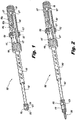
- FIG. 1 a perspective view of an assembled instrument 100 for inserting an implant in accordance with the subject technology is shown.
- the instrument 100 is particularly useful for inserting interspinous process implants and fusion cage spacers in accordance with those shown in U.S. PG Pub. No. 2010/0234889 (the '889 application).
- Figure 2 a perspective view of the insertion instrument 100 mounted with an implant 200 in accordance with the '889 application is shown.
- the instrument 100 can be disassembled easily to allow for full and proper cleaning, then reassembled to be used again.
- the components of the instrument 100 are fabricated from medical grade stainless steel, alloys, and/or polymers (e.g., RULON, PEEK) or another like durable material to allow for repeated use, cleaning and reuse.
- the instrument 100 includes an elongated main body 102 having a proximal handle portion 104 that defines a central passage 106 and a distal portion 108 that selectively couples to the implant 200.
- the distal portion 108 forms axial slots 109 that allows compression of the tip 113.
- the tip 113 is roughly hexagonal shaped but as a result of the opposing slots 109, the tip 113 becomes two opposing, spaced apart "V" in cross-sectional shape.
- the tip 113 has four outer ridges 111, one ridge 111 on each flat section of the V-shape.
- the handle portion 104 also has stripes 127 to provide visual references to the user.
- the handle portion 131 has a distal guide portion 133.
- the handle portion 104 of the main body 102 also has a first pair of opposing locking tabs 115.
- the locking tabs 115 are hingedly connected to the main body 102 to rotate radially inward and outward by the surgeon or surgical assistant.
- the handle portion 104 also has a second pair of opposing locking tabs 117 that are located relatively proximally compared to the first locking tabs 115.
- the second locking tabs 117 are also hingedly connected to the main body 102 to rotate radially inward and outward by the user.
- the handle portion 104 defines an axial recess 134.
- the axial recess 134 is formed by an angled surface 135 (best seen in Figure 7 ).
- the main body 102 also forms an axial wing slot 103 with location indicia 105a-c adjacent the wing slot 103 as described in more detail with reference to Figure 23 among other figures herein.
- the indicia 105a-c combine with the reference notch 131 on the wings to indicate "unlocked,” “locked” and “deployed” positions of the instrument 100, respectively, as described in more detail below.
- the main body 102 and spike cap drive 104 includes alignment indicia 123,127 in the form of stripes 127 and an arrow 123, respectively.
- a plunger 110 slides in the central passage 106.
- the plunger 110 has a distal pushing end 112 and a proximal locking end 114.
- the proximal locking end 114 has a relatively thicker radius that includes a series of spaced apart radial holes 118.
- Opposing radial wings 120 are formed adjacent a proximal recess 122.
- the radial wings 120 include a reference notch 131.
- the plunger 110 is shown coupled to a plunger knob 126.
- a plunger knob 126 has an externally threaded proximal end 128 that threadably couples to the axial threaded post 124 of the plunger 110.
- the plunger knob 126 has a proximal handle portion 130 for gripping to move the plunger 110 in the central passage 106.
- the plunger knob 126 has an annular recess 142 that extends completely around the plunger knob 126.
- the implant 200 comes in a variety of sizes so that an appropriate size can be selected for a desired amount of interspinous distraction. Any technique now known and later developed may be used to determine the proper interspinous distraction. Once the proper size implant 200 is selected, the corresponding or matching adapter 170 can be selected. Once the adapter 170 has been chosen, the implant 200 can be mounted on the insertion instrument 100.
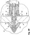
- Figure 28 is a dorsal view illustrating the implant 200 with the spike cap 230 urged distally by the nut 235, engaging the adjacent spinous processes 381a, 381b.
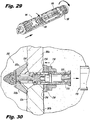
- Figure 30 is a dorsal view illustrating the implant 200 fixed in place with removal of the insertion instrument 100.
- the spike cap drive 140 is rotated clockwise relative to the main body 102 by the handle portion 148. Turning the handle portion 148 turns the adapter 170 and thereby the hex nut 235. Once the spike cap 230 engages the spinous processes 381a, 381b, the blades 220a, 220b are drawn proximally into engagement with the bone 381a, 381b. A flat portion of the implant 200 is not threaded so that the implant 200 slides proximally. While the spike cap drive 140 is used to tighten the hex nut 235, the surgeon can feel the spike cap 230 become fully seated or full seating is seen in an accompanying fluoroscopy display. Preferably, one or more osteogenesis promoting substances can be packed in and/or around the implant 200 to promote bone ingrowth and/or spinal fusion, if desired.
Landscapes
- Health & Medical Sciences (AREA)
- Orthopedic Medicine & Surgery (AREA)
- Surgery (AREA)
- Life Sciences & Earth Sciences (AREA)
- Neurology (AREA)
- Medical Informatics (AREA)
- Biomedical Technology (AREA)
- Heart & Thoracic Surgery (AREA)
- Engineering & Computer Science (AREA)
- Molecular Biology (AREA)
- Animal Behavior & Ethology (AREA)
- General Health & Medical Sciences (AREA)
- Public Health (AREA)
- Veterinary Medicine (AREA)
- Nuclear Medicine, Radiotherapy & Molecular Imaging (AREA)
- Prostheses (AREA)
- Surgical Instruments (AREA)
Description
- This application claims the benefit of and priority to
U.S. Provisional Patent Application No. 61/828,384 filed May 29, 2013 - The subject technology is directed to instruments for inserting spinal implants, and more particularly, to an insertion instrument that is easily assembled and disassembled for required cleaning while being able to effectively deploy an interspinous process implant for spinal stabilization, for percutaneous placement in a target interspinous process space, wherein the implant can also serve as a fusion cage spacer to treat lumbar spinal stenosis.
- The spine consists of a column of twenty-four vertebrae that extend from the skull to the hips. Discs of soft tissue are disposed between adjacent vertebrae. The vertebrae provide support for the head and body, while the discs act as cushions. In addition, the spine encloses and protects the spinal cord, defining a bony channel around the spinal cord, called the spinal canal. There is normally a space between the spinal cord and the borders of the spinal canal so that the spinal cord and the nerves associated therewith are not pinched.
- Over time, the ligaments and bone that surround the spinal canal can thicken and harden, resulting in a narrowing of the spinal canal and compression of the spinal cord or nerve roots. This condition is called spinal stenosis, which results in pain and numbness in the back and legs, weakness and/or a loss of balance. These symptoms often increase after walking or standing for a period of time.
- There are a number of non-surgical treatments for spinal stenosis. These include non-steroidal anti-inflammatory drugs to reduce the swelling and pain, and corticosteroid injections to reduce swelling and treat acute pain. While some patients may experience relief from symptoms of spinal stenosis with such treatments, many do not, and thus turn to surgical treatment. Some surgical procedures for treating spinal stenosis are decompressive laminectomy and interspinous process decompression (IPD).
- A well-known implant used for performing IPD surgery is the X-STOP® device, which is described in
U.S. Patent No. 6,419,676 . Another interspinous process implant placed in a minimally invasive surgical procedure is disclosed inU.S. Patent Application Publication 2008/0243250 . Still another interspinous process implant placed in a minimally invasive surgical procedure is disclosed inU.S. Patent Application Publication 2010/0234889 . One aspect of effective insertion of these implants is to provide a low profile instrument for deploying the implant. Often, the insertion instrument has several moving parts. Because of the cost of the insertion instruments, the instruments are re-used many times. For such insertion instruments to be re-used, the insertion instruments must be properly and fully cleaned without damage or loss of the components.US 2010/0057130 A1 discloses a conical interspinous apparatus including a distractor comprising an insertion portion and a central engagement groove, the insertion portion having a conical shape which tapers to a tip and is adapted to enable passage of the distractor between two spinous processes of vertebrae, and the central engagement groove is adapted to secure the distractor between the two spinous processes such that the two spinous processes rest in the central engagement groove. The conical interspinous apparatus includes a stabilizer which is adapted to be deployed from within the distractor to secure the two spinous processes within the central engagement groove and an insertion driver detachably coupled to a rear portion of the distractor. A guide wire, having a pointed tip, aids in the insertion of the distractor between the two spinous processes and is configured to guide the insertion of the distractor.CA 2 751 750 A1 discloses an interspinous process implant having deployable engagement arms. The implant includes an elongated body portion dimensioned and configured for percutaneous introduction into a target interspinous process space, at which interspinous distraction and/or spinal fusion are desired. The body portion can include a threaded outer surface, or alternatively a smooth surface. The body portion can include one or more interior cavities, and can include deployable engagement members adapted and configured to move in tandem between a stowed position retracted within the interior cavity of the body portion and a deployed position extended from the interior cavity of the body for engaging adjacent spinous processes. An internal drive assembly for selectively moving the engagement members from the stowed position to the deployed position can be provided, as can a elements for locking the engagement members in a deployed position.WO 2010/025408 A2 discloses a bone-derived interspinous spacer for implantation into an interspinous space located between spinous process of adjacent vertebrae. The spacer preferably includes a body, a core and a plurality of dep lovable retainers. The body may be operatively associated with the plurality of deployable retainers. In use, after the body has been inserted into the interspinous space, the plurality of retainers is deployed so that they prevent migration of the spacer. The core is preferably sized and configured to be inserted and/or moved into operatively engagement with the body to deploy the plurality of retainers. - It would be advantageous to provide an insertion instrument for deploying spinal implants that can be easily disassembled for cleaning and assembled for use.
- In one embodiment, the subject technology is directed to an insertion device for a spinal implant, wherein the spinal implant includes: a) an elongated body to function as a spacer placed in a target interspinous process space between two adjacent spinous processes, wherein the body defines an interior and a proximal internal recess for access to the interior, the proximal internal recess forming a transverse groove; b) a distal anchor that is at least partially threaded and has opposing radially deployable blades mounted for rotation about a pin transversely mounted in the interior; c) a proximal anchor including a spike cap mounted to slide along the body and a drive nut mounted for longitudinal movement along the body between a first position spaced apart from the distal anchor and a second position relatively closer to the distal anchor to thereby compress the two adjacent spinous processes between the spike cap and the distal anchor; and d) an actuation plunger slidably inside the interior for moving the blades from a stowed/insertion position to an implant deployed position.
- The insertion device includes an elongated main body having a distal locking portion for coupling to the implant and a proximal handle portion. The main body defines a central passage and the distal locking portion has outer ridges. The at least one slot allows at least one of the outer ridges to flex radially inward. A plunger slides in the central passage for movement between an unlocked position for mounting the implant on the distal locking portion, a locked position within the slot for locking the implant on the distal locking portion, and an insertion instrument deployed position for deploying the actuation plunger to move the blades from the stowed position to the deployed position. A spike cap drive rotatably mounts on the main body having a socket end for engaging the drive nut to, in turn, move the spike cap.
- Preferably, the insertion instrument includes a plunger stop coupled to the main body. The plunger stop has a central passage substantially aligned with the central passage of the main body, wherein: the plunger stop has a boss protruding into the central passage; and the plunger forms a three-part groove that captures the boss as the plunger slides and rotates within the central passage, the three-part groove having a first axial part that defines the unlocked position, an intermediate radial part that defines the locked position, and a second axial part that defines the insertion instrument deployed position. When the implant is mounted, in the unlocked position, the outer ridges are engaged in the transverse groove. In the locked position, the outer ridges are engaged in the transverse groove and the plunger extends through the central passage to be concentric with the outer ridges. In the insertion instrument deployed position, the plunger extends out of the central passage to move the actuation plunger of the implant.
- As the size of the implant may vary, adapters are matched to the implant for coupling the socket end to the drive nut of the implant. The spike cap may also be keyed to the implant body to prevent rotation when driven. The implant has flat portions that allow efficient compression of the implant when engaged in the spinous processes.
- In another embodiment, the subject technology is directed to an instrument for inserting an implant having a threaded body, selectively deployable distal blades, and a selectively deployable proximal anchor. The instrument includes an elongated main body having a proximal handle portion that defines a central passage and a distal portion that selectively couples to the implant. A plunger slides in the central passage to fix the implant to the elongated main body and deploy the distal blades. A spike cap drive is concentrically located about the plunger to deploy the proximal anchor. Preferably, the implant defines an interior with a transverse groove, the distal portion snaps into the transverse groove, and the plunger slides down central passage to prevent the distal portion from unsnapping from the transverse groove. The plunger can move between an unlocked position for mounting the implant on the distal portion, a locked position for locking the implant on the distal locking portion, and an insertion instrument deployed position for deploying the blade.
- In still another embodiment, the subject technology is directed to an insertion instrument for inserting an implant having a body that defines a mounting recess. The insertion instrument includes an elongated main body having a proximal handle portion and a slotted distal portion that selectively couples to the mounting recess of the implant. A plunger slides in a central passage of the elongated main body for fixing the implant to the elongated main body by selectively filling the central passage within the slotted distal portion. Preferably, the implant defines an interior connected to the mounting recess. The implant may further include selectively deployable distal blades, and the plunger deploys the distal blades by extending out of the central passage into the interior.
- The implant can further include a selectively deployable proximal anchor and the insertion instrument further comprises a spike cap drive concentrically located about the plunger and elongated main body to deploy the proximal anchor. The mounting recess may have a transverse groove so that the distal portion has ridges that snap into the transverse groove.
- It should be appreciated that the present technology can be implemented and utilized in numerous ways, including without limitation as a process, an apparatus, a system, a device, a method for applications now known and later developed. These and other unique features of the technology disclosed herein will become more readily apparent from the following description and the accompanying drawings.
- So that those skilled in the art to which the subject invention relates will readily understand how to make and use the insertion instrument of the subject technology without undue experimentation, embodiments thereof will be described in detail herein below with reference to the following figures.
-
Figure 1 is a perspective view of an insertion instrument in accordance with a first exemplary embodiment of the subject technology. -
Figure 2 is a perspective view of the insertion instrument ofFigure 1 with an implant in accordance with a first exemplary embodiment of the subject technology. -
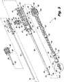
Figure 3 is an exploded view of the insertion instrument ofFigure 1 , illustrating the components thereof. -
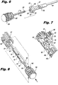
Figure 4 is a further exploded view of the spike cap drive of the insertion instrument ofFigure 1 , illustrating the components thereof. -
Figure 5 is a perspective view of the main body ready to engage the spike cap drive of the insertion instrument ofFigure 1 . -
Figure 6 is a further exploded view of the plunger and plunger knob of the insertion instrument ofFigure 1 , illustrating the components thereof. -
Figure 7 is a perspective view of the plunger stop being coupled to the main body of the insertion instrument ofFigure 1 . -
Figure 8 is a perspective view of the plunger being coupled to the main body of the insertion instrument ofFigure 1 . -
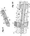
Figure 9 is a perspective view of the assembled main body of the insertion instrument ofFigure 1 . -
Figure 10 is a cross-sectional view of the insertion instrument ofFigure 9 taken at line 10-10 ofFigure 9 , where the plunger is an unlocked position. -
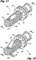
Figure 11 is a perspective view of the implant with blades in a stowed position. -
Figure 12 is a perspective view of the implant with blades in a deployed position. -
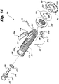
Figure 13 is a rear exploded view of the implant in accordance with the subject technology. -
Figure 14 is a front exploded view of the implant in accordance with the subject technology. -
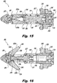
Figure 15 is a cross-sectional view of the implant ofFigures 11-14 taken at line 15-15 ofFigure 11 , where the distal anchor elements are in a stowed position. -
Figure 16 is a cross-sectional view of the implant ofFigures 11-14 taken at line 16-16 ofFigure 11 , where the distal anchor elements are in a deployed position. -
Figure 17 is a perspective view of the spike cap drive being retracted from the distal tip of the main body of the insertion instrument ofFigure 1 . -
Figure 18 is a perspective view of the adapter mounted on the spike cap drive of the instrument ofFigure 1 about to be coupled to the implant. -
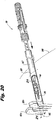
Figure 19 is a side elevational view of the insertion instrument ofFigure 1 with the implant mounted thereon. -
Figure 20 is a perspective view, illustrating an implant in preparation to be installed dorsally. -
Figure 21 is a dorsal view of an implant within an introducer tube during lateral insertion thereof. -
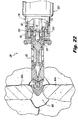
Figure 22 is a dorsal view illustrating the implant being screwed into a target interspinous process space. -
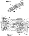
Figure 23 is a perspective view of the insertion instrument with the plunger stop actuated to move the plunger from the locked to the deployed position. -
Figure 24 is a cross-sectional view of the insertion instrument showing the plunger and plunger stop as the implant blades are being deployed. -
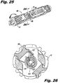
Figure 25 is a perspective view of the insertion instrument illustrating the spike cap drive being utilized to turn the hex nut of the implant. -
Figure 26 is a cross-sectional view of the insertion instrument showing the plunger and plunger stop in the locked position. -
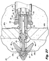
Figure 27 is cross-sectional view illustrating the deployment of the blades of the implant. -
Figure 28 is a cross-sectional view illustrating the spike cap drive securing the implant to the spinous processes. -
Figure 29 is a perspective view of the insertion instrument with the plunger being retracted from the implant in preparation to remove the insertion instrument from the implant after deployment of the implant in the spinal column. -
Figure 30 is a dorsal cross-sectional view of the implant fixed in the spinal column with the insertion instrument removed. - The present disclosure overcomes many of the prior art problems associated with instruments for inserting spinal implants and other devices such as cage spacers and the like. The advantages and other features of the instruments disclosed herein will become more readily apparent to those having ordinary skill in the art from the following detailed description of certain preferred embodiments taken in conjunction with the drawings which set forth representative embodiments of the present invention and wherein like reference numerals identify similar structural elements.
- All relative descriptions herein such as left, right, up, and down are with reference to the Figures, and not meant in a limiting sense. The illustrated embodiments can be understood as providing exemplary features of varying detail of certain embodiments, and therefore, features, components, modules, elements, and/or aspects of the illustrations can be otherwise combined, interconnected, sequenced, separated, interchanged, positioned, and/or rearranged without materially departing from the disclosed systems. The shapes and sizes of components are also exemplary and unless otherwise specified, can be altered without materially affecting or limiting the disclosed technology.
- Referring now to
Figure 1 , a perspective view of an assembledinstrument 100 for inserting an implant in accordance with the subject technology is shown. Theinstrument 100 is particularly useful for inserting interspinous process implants and fusion cage spacers in accordance with those shown in U.S. PG Pub. No.2010/0234889 (the '889 application). Referring additionally toFigure 2 , a perspective view of theinsertion instrument 100 mounted with animplant 200 in accordance with the '889 application is shown. - After use, the
instrument 100 can be disassembled easily to allow for full and proper cleaning, then reassembled to be used again. Preferably, the components of theinstrument 100 are fabricated from medical grade stainless steel, alloys, and/or polymers (e.g., RULON, PEEK) or another like durable material to allow for repeated use, cleaning and reuse. - Referring to
Figure 3 , an exploded view of theinstrument 100 with animplant 200 is shown. Theinstrument 100 includes an elongatedmain body 102 having aproximal handle portion 104 that defines acentral passage 106 and adistal portion 108 that selectively couples to theimplant 200. Thedistal portion 108 formsaxial slots 109 that allows compression of thetip 113. Thetip 113 is roughly hexagonal shaped but as a result of the opposingslots 109, thetip 113 becomes two opposing, spaced apart "V" in cross-sectional shape. Thetip 113 has fourouter ridges 111, oneridge 111 on each flat section of the V-shape. Thehandle portion 104 also hasstripes 127 to provide visual references to the user. - The
handle portion 131 has adistal guide portion 133. Thehandle portion 104 of themain body 102 also has a first pair of opposing lockingtabs 115. The lockingtabs 115 are hingedly connected to themain body 102 to rotate radially inward and outward by the surgeon or surgical assistant. Thehandle portion 104 also has a second pair of opposing lockingtabs 117 that are located relatively proximally compared to thefirst locking tabs 115. Thesecond locking tabs 117 are also hingedly connected to themain body 102 to rotate radially inward and outward by the user. Thehandle portion 104 defines anaxial recess 134. Theaxial recess 134 is formed by an angled surface 135 (best seen inFigure 7 ). - The
main body 102 also forms anaxial wing slot 103 withlocation indicia 105a-c adjacent thewing slot 103 as described in more detail with reference toFigure 23 among other figures herein. Theindicia 105a-c combine with thereference notch 131 on the wings to indicate "unlocked," "locked" and "deployed" positions of theinstrument 100, respectively, as described in more detail below. Themain body 102 andspike cap drive 104 includes alignment indicia 123,127 in the form ofstripes 127 and anarrow 123, respectively. - A
plunger 110 slides in thecentral passage 106. Theplunger 110 has a distal pushingend 112 and aproximal locking end 114. Theproximal locking end 114 has a relatively thicker radius that includes a series of spaced apartradial holes 118. Opposingradial wings 120 are formed adjacent aproximal recess 122. Theradial wings 120 include areference notch 131. InFigure 3 , theplunger 110 is shown coupled to aplunger knob 126. - Referring now to
Figure 6 , an exploded view of theplunger 110 andplunger knob 126 is shown. Theproximal recess 122 has internal threads that are left-handed. Theproximal locking end 114 also forms a three-part groove 116. The three-part groove 116 has a first distalaxial groove portion 119 and a second proximalaxial groove portion 125. Intermediate thegroove portions proximal locking end 114 forms aradial groove portion 121. - A
plunger knob 126 has an externally threadedproximal end 128 that threadably couples to the axial threaded post 124 of theplunger 110. Theplunger knob 126 has aproximal handle portion 130 for gripping to move theplunger 110 in thecentral passage 106. At the distal end of thehandle portion 130, theplunger knob 126 has anannular recess 142 that extends completely around theplunger knob 126. - Referring again to
Figure 3 as well asFigures 7 and9 , a plunger stop 132 seats in arecess 134 formed in thehandle portion 104 of themain body 102 to guide theplunger 110 within themain body 102. Theplunger stop 132 has two outer opposinglands 138 that facilitate a user holding theplunger stop 132 and manipulating position of the plunger stop 132 with their thumbs. Theplunger stop 132 hastubular portion 137 that defines anaxial passage 136 for receiving theplunger locking end 114. Aboss 139, best seen inFigures 7 and10 , extends radially inward from theaxial passage 136 to engage thegroove 116 of theplunger locking end 114. A biasingspring 141 surrounds thetubular portion 137 such that ends 143 of thespring 141 extend outward. - Still referring to
Figure 3 , aspike cap drive 140 defines anaxial passage 144 for receiving thedistal end 108 of themain body 102. Thespike cap drive 140 has aproximal portion 146 that includes a relatively largerradius handle portion 148 with a smallerradius interlocking portion 150. The interlockingportion 150 defines anannular groove 152 for interacting with themain body 102. A tubularintermediate portion 154 extends from thehandle portion 148 and slidingly receives adrive shaft 160. Thedrive shaft 160 terminates in asocket end 156. Thesocket end 156 is also tubular but forms asquare opening 158 for coupling to theimplant 200. Thesocket end 156 also forms a transversesquare locking passage 157. - The
drive shaft 160 is also able to be locked in a retracted position within theintermediate portion 154. Referring now toFigure 4 , an exploded view of thespike cap drive 140 is shown. Thespike cap drive 140 has aspring 163 mounted within theintermediate portion 154 for biasing thedrive shaft 160 distally. So, in order to lock thedrive shaft 160 in a retracted position, the bias of thespring 163 must be overcome. To accomplish this locking, thedrive shaft 160 forms two opposing complimentary slots 161 (only oneslot 161 can be seen) and pins 165 mount in opposing pin holes 167 on theintermediate portion 154. When assembled, thepins 165 ride in therespective slots 161 so that upon fully pushing thedrive shaft 160 in theintermediate portion 154, a small rotation of thedrive shaft 160 will set thepins 165 in aradial portion 164 of theslots 161 and retain thespike cap drive 140 in this compressed position. - Referring again to
Figure 3 , anadapter 170 attaches to thesquare opening 158 of thespike cap drive 140 to provide ahex socket 172 for coupling to theimplant 200. Thehex socket 172 can vary in size to accommodatedifferent size implants 200. Theadapter 170 has a centralaxial passage 173 to slide over thetip 113 of themain body 102. Theadapter 170 has a standard male square openproximal end 174 to couple to thesquare opening 158. Theproximal end 174 has two opposingrigid legs 175 intermediate two opposingflexible legs 176. Each of theflexible legs 176 has alocking tab 177 so that as theproximal end 174 is pushed into thesquare opening 158 of thespike cap drive 140, thelegs 176 deflect to allow easy insertion, then thetabs 177 couple to thetransverse locking passage 157 to securely retain theadapter 170 on thedrive shaft 160. To remove theadapter 170, the lockingtabs 177 are simply depressed while retracting theadapter 170. Theadapter 170 also has opposing outeraxial alignment ridges 178. - The
implant 200 may take a variety of different configurations and sizes. Preferably, the implant is useful for treatment of spondylolisthesis, central and foraminal lumbar stenosis, degenerative disc disease and the like. Beneficially, theimplant 200 is percutaneously placed, provides stabilization of the spine, can be used with bone graft material to promote fusion, requires less than a 2.6 cm incision, and can be inserted with local or general anesthesia. As such, the recovery time is relatively quicker and the hospital stay is relatively shorter. -
Figures 11-16 illustrate in detail theinterspinous process implant 200 for use the withinsertion instrument 100. Theimplant 200 includes abody 212, providing overall structure to theimplant 200. Thebody 212, as illustrated, is provided withthreads 222 for facilitating insertion of theimplant 200 into a target interspinous process space 382 (Figures 20-22 ,27 ,28 and30 ), as will be described in more detail below in connection withFigures 20-30 , as well as for providing additional engagement with the anatomy of the patient in the targetinterspinous process space 382. Further, thethreads 222 permit rotational engagement between thebody 212 and aproximal nut 235, provided to securely engage theimplant 200 withinterspinous processes interspinous process space 382, which will be described in more detail below. Alternatively, theimplant 200 can be provided without threads thereon, or with threads provided only on a portion thereof for one of the foregoing functions. That is, if desired,threads 222 can be provided only on the proximal end of thebody 112, for engaging thenut 235 and not on the distal portion, or vice versa. - The
implant 200 include a distal anchor portion, which is configured as two opposed deployable blades 220 (220a, 220b). The blades 220 are provided with a common pivot, defined by apin 259 passing therethrough, as well as through thebody 212. Use of a common pivot advantageously minimizes the space required for housing all elements within thebody 212 in their stowed state, although variations from this precise configuration are possible. For example, two separate pivots can be provided for eachblade spikes 224 for engaging the relevant adjacent bony anatomy, such as thespinous processes such spikes 224. - The
blades hinge portions 223a, 223b for engaging thepin 259. In the illustrated embodiment, onehinge portion 223a is shaped as a clevis, while the other 223b is shaped to fit within the clevis-shapedhinge portion 223a. - In the illustrated embodiment, an
implant plunger 226 is provided and includes ahead portion 228 shaped and configured to act as a cam and cooperate with inner cam surfaces 240 formed on each of theblades plunger head 228 moves distally, cam surfaces 240 of theblades plunger head 228, and urge theblades plunger 226 can include, as described above, aproximal head 225 having a proximalinternal recess 221, and an angled distal surface to facilitate distally-directed urging and proximal-directed urging, respectively, applied from the proximal direction. - Preferably, the
implant plunger 226 also includes arecess 229, for securely engaging aresilient catch 227. Thecatch 227 is configured to interface between theimplant plunger 226 and internal surface features of thebody 212, such as annular grooves or recesses 254. As described, theresilient catch 227 permits axial movement of theimplant plunger 226, and in conjunction with the above-described internal surface features of thebody 212, defined positions at which theimplant plunger 226 is held, inhibiting unintentional movement therefrom. Thecatch 227 can be formed of any suitable material or configuration, such as from a resilient material, such as an elastomer, or as a resilient structure, such as a toroidal metallic coil, or a combination of these, for example. Thecatch 227 can be, in accordance with the invention, a canted coil, such as a Bal Latch™, available from Bal Seal Engineering, Inc. of Foothill Ranch, California, USA. - When deployed, the blades 220 function in concert with the
spike cap 230, which is axially moveable along the length of theimplant 200. Thenut 235 includes threads on its inner surface that engage thethreads 222 provided on the outer surface of thebody 212. Accordingly, rotational movement of thenut 235 yields axial movement thereof. When that axial movement is in the distal direction, thenut 235 urges thespike cap 230 distally until thespike cap 230 abuts the bony structures (e.g.spinous processes interspinous process space 382. If provided, protrusions or spikes 234 on the proximal anchor portion facilitate engagement with the bone and thus stabilization of the entire vertebrae-implant construct. - As illustrated, opposed flat portions 217, comprising upper and lower
flat portions 217a, 217b, respectively, guide correspondingly shaped (e.g., flat)portions 237 of thespike cap 230, permitting axial movement but inhibiting rotational movement thereof, during movement of thenut 235. Alock washer 233 or equivalent feature can be provided to inhibit unintentional loosening of thenut 235 following implantation and deployment of theblades - With reference to the cross-sectional views of
Figures 15 and 16 , in the illustrated embodiment, the blades 220 can be provided with aninternal spring element 281, spanning between respective recess in each of theblades spring element 281 can be provided straight to maintain theblades blades spring element 281 is provided bent, and urges theblades implant plunger 226, thespring 281 serves to maintain a position of the blades 220. As illustrated, when theimplant plunger 226 is fully extended, ahead portion 228 thereof engages acorresponding detent 249 in theblades detent 249 by thehead portion 228 further ensures secure deployment of theblades - The
spring element 281 can alternatively be provided as normally straight, urging theblades spring element 281 permits inward rotation of theblades spring element 281 in the process. Thus, during implantation thespring 281 serves to maintain a position of theblades interspinous process space 382, theimplant plunger 226 can be urged distally in order to lock theblades detent 249 by thehead portion 228 of theimplant plunger 226 further ensures maintenance of that position. - The
body 212 of theimplant 200 includes at its proximal end, an expanded-diameter portion 213, defining a proximal-most limit for traveling of thenut 235 andspike cap 230. Also in the proximal end portion, formed within the proximalinternal recess 250, is a shapedsocket 251 for engagement with theinsertion instrument 100 as discussed in more detail below. As illustrated, thesocket 251 is substantially hexagonal, with flat portions defined at regular angular intervals. Practicable departures from the precise configuration illustrated are possible. The shapedsocket 251 facilitates mutual rotational engagement between theimplant 200 and theinsertion instrument 100. - Also provided in connection with the
socket 251, aretransverse grooves 253, which, in conjunction with thetip 113 of themain body 102 and pushingend 112 of theplunger 110 mount and lock theimplant 100 to theinsertion instrument 100. The mounting and/or locking elements on the insertion instrument can also be, for example, a resiliently and optionally lockable protrusion extending laterally (i.e., radially) from the insertion instrument. The lockable protrusion may be, for example, a lockable springloaded spherical element, for example. - The
implant 200 can be provided with one ormore apertures 214 to permit packing of the implant, such as in the proximalinternal recess 250 thereof, with osteogenesis-promoting substances to facilitate bone ingrowth and/or fusion, such as demineralized bone. - Referring now to
Figures 3 and5 , in order to assemble theinsertion instrument 100, thedistal portion 108 of themain body 102 is inserted into theaxial passage 144 of thespike cap drive 140 until theproximal handle portion 104 is flush against thehandle portion 148 of thespike cap drive 140. Thefirst locking tabs 115 are rotated from the open position shown inFigure 5 to the closed position shown inFigure 1 . Thefirst locking tabs 115 axially lock themain body 102 and thespike cap drive 140 together. The locking occurs by the lockingtabs 115 extending into theannular groove 152 of thespike cap drive 140 and snapping fixedly into place. Preferably, the user hears an audible click to know that the engagement of thetabs 115 into thegroove 152 has been fully completed. Thespike cap drive 140 can still rotate with respect to themain body 102. Thedistal guide portion 133 of themain body 102 is sized so that thespike cap drive 140 rotates smoothly. A suitable material or coating may be used in contact areas to prevent wear and galling. - Referring to
Figures 6-8 , the threadeddistal end 128 of theplunger knob 126 is partially threaded into therecess 122 of theplunger 110 as shown inFigure 6 . Theplunger knob 126 is turned counter-clockwise because the threading is left-handed. Theplunger stop 132 is seated in therecess 134 of themain body 102 as shown inFigure 7 . Theplunger stop 132 is seated with theends 143 of thespring 141 against theangled surface 135 so that theplunger stop 132 will be biased for clockwise rotation when one looks down theinsertion instrument 100 from the proximal to the distal direction. - While holding the
plunger stop 132 in place with one hand, theplunger 110 can be partially inserted into thecentral passage 106 of themain body 102 by holding theplunger knob 126 with the other hand as shown inFigure 8 . As noted above, at this point, theplunger knob 126 need not be completely threaded into theplunger 110 but theplunger knob 126 may be. Theradial wings 120 will slide in theslot 103 of themain body 102 so that thereference notch 131 is adjacent theindicia 105a-c. - As the
plunger 110 is inserted through theplunger stop 132, the user applies rotational force to the plunger stop 132 by using the thumb lands 138 to make sure that the plunger stopboss 139 aligns with the distalaxial groove portion 119. The user must apply enough force to overcome thespring 141 because thespring 141 biases the plunger stop 132 theaxial groove portion 119 towards theradial groove portion 121. Once the plunger stopboss 139 is in the distalaxial groove portion 119, as shown inFigure 10 , and theplunger knob 126 is flush against theproximal handle portion 104 of themain body 102, the second pair of opposing lockingtabs 117 are clicked into theannular recess 142 of theplunger knob 126 as shown inFigure 9 . As a result, theplunger 110 andplunger knob 126 are axially locked to themain body 102. - Referring to
Figure 10 , when the plunger stopboss 139 is in the first distalaxial groove portion 119, rotation of theplunger 110 is prevented until theboss 139 reaches theradial groove portion 121 of theplunger 110. However, rotation of theplunger knob 126 is still possible. - While the
boss 139 is in theaxial groove portion 119 and both pairs of lockingtabs instrument 100 is in the "unlocked" position as visually indicated to the user by thereference notch 131 being adjacent theunlocked indicia 105a. "Unlocked" refers to theimplant 200 not being secured to theinsertion instrument 100 even if theimplant 200 is mounted on thetip 113. Theimplant 200 is locked to theinsertion instrument 100 by deploying theplunger 110 as described below. - As would be understood from the description above, even once assembled, several components of the
insertion instrument 100 are able to move. Thus, it is important to make sure the moving components are in the proper position to be ready for mounting theimplant 200. In particular, theplunger 110 should be fully retracted into the unlocked position by turning theplunger knob 126 counter clockwise while rotating and holding the plunger stop 132 to allowplunger 110 travel (i.e., theboss 139 of theplunger stop 132 is aligned with the first axialdistal groove portion 119 of theplunger 110 as shown inFigure 10 ). Once theplunger 110 is fully retracted, thereference notch 131 will indicate fully unlocked on theunlocked indicia 105a. - Turning to the selection of the
implant 200, it is envisioned that theimplant 200 comes in a variety of sizes so that an appropriate size can be selected for a desired amount of interspinous distraction. Any technique now known and later developed may be used to determine the proper interspinous distraction. Once theproper size implant 200 is selected, the corresponding or matchingadapter 170 can be selected. Once theadapter 170 has been chosen, theimplant 200 can be mounted on theinsertion instrument 100. - Referring now to
Figure 17 , thedistal portion 108 of themain body 102 is uncovered by sliding thedrive shaft 160 into theintermediate portion 154 of thespike cap drive 140. Thedrive shaft 160 is initially prevented from rotation because thepins 165 are riding in the slots 161 (best seen inFigure 4 ). However, once thepins 165 bottom out in theslots 161, the user can hold thehandle portion 148 and rotate thedrive shaft 160 so thepins 165 come to rest in theradial portion 164 of theslots 161. As a result, thedrive shaft 160 is retained in theintermediate portion 154 and will stay retracted even when released by the user. - Referring now to
Figure 18 , the matchingadapter 170 is slid over thedistal portion 108 of themain body 102 so that thelegs square opening 158. Preferably, the lockingtabs 177 provide an audible click when thelegs 176 deflect outward into thetransverse locking passage 157 to confirm positive engagement for the user. The user can also visually confirm proper positioning of theadapter 170 because thealignment ridge 178 should align with theindicator arrow 123 on thesocket end 156 as shown inFigure 19 . - Referring to
Figures 18 and 19 , after positioning theadapter 170 on thedrive shaft 160, theimplant 200 can be partially engaged to thetip 113 by a snap friction fit. Thetip 113 is slightly compressed, by virtue of theslots 109, and passed into the proximalinternal recess 250 of theimplant 200 with theblades implant 200 aligned with theslots 109,arrow 123 andstripes 127 of themain body 102. As a result, the surgeon can determine proper blade orientation visually prior to and during insertion. Thetip 113 stops within therecess 250 when theridges 111 seat into thetransverse groove 253. At this point, theimplant 200 is coupled to theinsertion instrument 100 but not yet "locked." - To lock the
implant 200 to theinstrument 100, theplunger 110 is moved from the unlocked position to the locked position. To move theplunger 110 distally, theplunger knob 126 is rotated clockwise (looking from the proximal end). As the threads are left-handed, theplunger 110 will move towards thedistal tip 113. As theplunger 110 moves, the first distalaxial groove portion 119 passes along theboss 139 of theplunger stop 132 until theboss 139 aligns with theradial portion 121 of thegroove 116. When theboss 139 aligns with theradial portion 121 of thegroove 116, theplunger stop 132 rotates clockwise because of the bias of thespring 141. Theboss 139 passes into theradial portion 121 and further axial movement is prevented. Thereference notch 131 of thewing 120 is at the locked indicia 105b and the insertion instrument is in the locked position. - In the locked position, the distal pushing
end 112 of theplunger 110 is approximately flush with thedistal tip 113 of themain body 102. Thus, theslots 109 of themain body 102 can no longer flex to allow theridges 111 out of thetransverse groove 253 best seen inFigure 22 . Consequently, theimplant 200 is tightly coupled and locked to thetip 113 so that inadvertent removal does not occur. Theinsertion instrument 100 is now ready to have thesocket end 156 of thespike cap drive 140 engaged to thehex nut 235 of theimplant 200. - To engage the
spike cap drive 140 to thehex nut 235 of theimplant 200, thehandle portion 148 is held to prevent rotation while thedrive shaft 160 is rotated to bring thepins 165 out of theradial portion 164 of theslots 161. Thespring 163 will bias thedrive shaft 160 outward so care should be taken to slowly extend thedrive shaft 160 to have thehex socket 172 properly engage thehex nut 235 of the implant 200 (best seen inFigure 22 ). In order to have thehex socket 172 properly engage thehex nut 235, a slight manual rotation or jiggle of thedrive shaft 160 may be required. Theimplant 200 is now locked to theinsertion instrument 100 to be ready for spinal implantation. The force provided by thespring 163 is optimized to insure proper, reliable engagement between theadapter 170 andhex nut 235 while providing excessive force to interfere with the operation of theinsertion instrument 100 or deployment of theimplant 200. -
Figures 20-24 illustrate various stages during insertion and placement of theimplant 200 into a targetinterspinous process space 382. In short,Figure 20 is a perspective view of theimplant 200 locked to theinsertion instrument 100, in preparation to be installed dorsally through acurved introducer tube 387, which has been inserted through anincision 389 formed through theskin 388 of a patient.Figure 21 is a dorsal (rear) view of theimplant 200, still held by the elongatedinsertion instrument 100, within a lumen of anintroducer tube 387, during lateral insertion thereof. -
Figure 22 is a dorsal view illustrating theimplant 200 being laterally advanced to the targetinterspinous process space 382, under application of a rotational force applied by theinsertion instrument 100, by virtue of thethreads 222 provided on thebody 212 thereof.Figure 27 is a dorsal view illustrating theimplant 200 with theinternal implant plunger 226 urged distally, effecting deployment of the distal anchor elements- in this case,blades nut 235 is then tightened, which urges thebody 212 proximally, and thus also urges the blades 220 more securely against the adjacent bony structure, impinging thespinous processes Figure 28 , which is a dorsal view illustrating theimplant 200 with thespike cap 230 urged distally by thenut 235, engaging the adjacentspinous processes Figure 30 is a dorsal view illustrating theimplant 200 fixed in place with removal of theinsertion instrument 100. - More particularly, as seen in
Figure 20 , asleeve 387 is provided to facilitate insertion. The insertion methods can include use of a stylet, dilators, and the like to gain access and define a path for thesleeve 387, as will be described in more detail below. However, dorsal insertion can be accomplished as set forth inU.S. Patent Application Serial No. 12/011,905, filed January 30, 2008 (U.S. Pub. No. 2009/0054988 ). As illustrated, inFigure 20 , dorsal insertion of the subject implants, represented byimplant 200, can be effected by forming anincision 389 through theskin 388 of a patient, at a level corresponding to a targetinterspinous process space 382, defined between adjacentvertebral processes Figure 20 , the path traversed by theimplant 200, and therefore also by thesleeve 387 is curved to align the path and theimplant 200 with the targetinterspinous process space 382. As such, theinsertion instrument 100 may be flexible and/or curved to match the curve of thesleeve 387. -
Figure 21 , in contrast, illustrates direct lateral insertion of theimplant 200 into the targetinterspinous process space 382. In this arrangement, an incision is formed in theskin 388 of a patient, and ultimately asleeve 387 is advanced through the tissue to the targetinterspinous process space 382, through which theimplant 200 is advanced, connected to theinsertion instrument 100. As shown inFigures 21 and22 , of whichFigure 22 is illustrated for clarity without thesleeve 387, theimplant 200 is axially rotated by way of theinsertion instrument 100, thus threading theimplant 200 into the targetinterspinous process space 382, distracting the adjacentspinous processes implant 200, generally centered with respect to thespinous processes - To rotate the
implant 200, theproximal handle portion 103 of themain body 102 is rotated in a tightening or clockwise direction to self-thread theimplant 200 through theinterspinous space 382 as shown inFigure 22 . During the rotation of theimplant 200, theimplant 200 distracts the interspinous space. Relative rotation and axial translation between theimplant 200 and theinsertion instrument 100 is inhibited because theimplant 200 is locked onto thetip 113 by the distal pushingend 112 of theplunger 110. Distraction can also be performed in advance by a separate instrument, with insertion of theimplant 200 following, and maintaining such distraction. - When anchoring
blades interspinous space 382 as shown inFigure 27 , theanchoring blades Figures 23 and 24 , to deploy theanchoring blades plunger stop 132 is rotated so that theboss 139 moves out of theradial groove portion 121 of theplunger 110. As such, theplunger 110 becomes free to move with theaxial portion 125 sliding along theboss 139 of the plunger stop 132 as shown best inFigure 24 . To accomplish the proximal movement of theplunger 110, theplunger stop 132 is held and theplunger knob 126 is turned clockwise or in a tightening motion. Because the threading is left-handed, theplunger 110 will move away from theplunger knob 126. Thereference notch 131 will slide toward the "deployed" position indicia 105c as the second proximalaxial groove portion 125 rides along theboss 139. - As the
plunger 110 extends distally, the distal pushingend 112 seats in therecess 221 of theimplant plunger 226. As theplunger 110 continues to move distally, the pushingend 112 applies pressure and moves theimplant plunger 226 distally to deploy theblades Figure 27 . Once fully deployed, thereference notch 131 will be adjacent the "deployed"indicia 105c and turning of theplunger knob 126 can stop. The physician can also verify proper deployment of theblades blades implant 200 can be set in final position. - Referring now to
Figure 28 , thehex nut 235 of theimplant 200 is shown being driven by thespike cap drive 140 to engage thespikes spinous processes spike cap drive 140 rotates thehex nut 235 to move thespike cap 230 distally. Because thespike cap 230 is keyed to theimplant 200 to prevent rotation, as thehex nut 235 turns, thespike cap 230 slides distally. - To rotationally drive the
hex nut 235, thespike cap drive 140 is rotated clockwise relative to themain body 102 by thehandle portion 148. Turning thehandle portion 148 turns theadapter 170 and thereby thehex nut 235. Once thespike cap 230 engages thespinous processes blades bone implant 200 is not threaded so that theimplant 200 slides proximally. While thespike cap drive 140 is used to tighten thehex nut 235, the surgeon can feel thespike cap 230 become fully seated or full seating is seen in an accompanying fluoroscopy display. Preferably, one or more osteogenesis promoting substances can be packed in and/or around theimplant 200 to promote bone ingrowth and/or spinal fusion, if desired. - A separate tap can be used in the target
interspinous process space 382 before the insertion of theimplant 200, or as mentioned above, theimplant 200 can be provided with features that provide self-tapping capability. Methods of lateral insertion of thespinal implant 200 into a targetinterspinous process space 382 can include, following forming the incision, inserting a stylet (not illustrated) through the incision 399, laterally to the targetinterspinous process space 382, preferably using an internal imaging technique, such as fluoroscopy. - Referring now to
Figures 29 and 30 , once theimplant 200 is properly deployed, theinsertion instrument 100 is disengaged from theimplant 200. To disengage theinsertion instrument 100, thedrive shaft 160 of thespike cap drive 140 is retracted into theintermediate portion 154 with thepins 165 captured in theradial portion 164 of theslot 161 following the same procedure as described above so that theadapter 170 disengages from thehex nut 235. Theplunger stop 132 is rotated and held by the user's thumb so that thegroove 116 will ride from the proximalaxial portion 125 to the distalaxial portion 119 without passing into theradial portion 121. To withdraw theplunger 110, theplunger knob 126 is loosened or rotated in the counter-clockwise direction relative to thehandle portion 104 of themain body 102 until thereference notch 131 fully indicates the "unlocked" position next to theunlocked indicia 105a. As theplunger 110 withdraws from thetip 113, theslots 109 are again allowed to flex so that thetip 113 pops out of the proximalinternal recess 250 of theimplant 200. With theadapter 170 disengaged and theplunger 110 retracted to the unlocked position, the coupling force of thetip 113 to theimplant 200 can be overcome to fully detach theinsertion instrument 100. Once removed, theinsertion instrument 100 can be removed from the patient for disassembly, cleaning and re-use. - Referring now to
Figures 29 and 30 , once theimplant 200 is properly deployed, theinsertion instrument 100 is disengaged from theimplant 200. To disengage theinsertion instrument 100, theplunger knob 126 is loosened or rotated in the counter-clockwise direction relative to thehandle portion 104 of themain body 109 to withdraw theplunger 110 until thereference notch 131 fully indicates the "locked" position next to the unlocked indicia 105b. Theplunger stop 132 clicks over, bringing theboss 139 into theradial groove portion 121, and engages to prevent further loosening of theplunger 110. Theplunger stop 132 is rotated and held by the user's thumb so that thegroove 116 will ride from theradial groove portion 121 to the distalaxial portion 119. This retraction of theplunger 110 may also be accomplished without theboss 139 passing into theradial groove portion 121. As theplunger 110 withdraws from thetip 113 by further counter-clockwise rotation of theplunger knob 126, theslots 109 are again allowed to flex so that thetip 113 can pop out of the proximalinternal recess 250 of theimplant 200. With theadapter 170 disengaged and theplunger 110 retracted to the unlocked position, the coupling force of thetip 113 to theimplant 200 can be overcome to fully detach theinsertion instrument 100. Once removed, theinsertion instrument 100 can be removed from the patient for disassembly, cleaning and re-use. - It is advantageous to disassemble the
insertion instrument 100 for cleaning. Referring toFigures 3-10 in reverse, the lockingtabs 117 that retain theplunger 110 are flipped up to unlock theplunger 110. As long as theplunger 110 is in the unlocked position, theplunger 110 can then be removed from themain body 102. Theplunger knob 126 can be unscrewed from theplunger 110. Once theplunger 110 is removed, the plunger stop 132 can also be removed from themain body 102. Next, the lockingtabs 115 that retain thespike cap drive 140 are released so that thespike cap drive 140 can be removed from themain body 102. Theadapter 170 can be unsnapped from thespike cap drive 140. At this point, the components of theinsertion instrument 100 are ready to be cleaned. - Below is Table 1, which is a parts list for the
insertion instrument 100 andimplant 200 illustrated in the figures.TABLE 1 Part Ref. No. insertion instrument 100 elongated main body 102 axial wing slot 103 proximal handle portion 104 "unlocked" position indicia 105a "locked" position indicia 105b "deployed" position indicia 105c central passage 106 distal portion 108 forms axial slots 109 plunger 110 outer ridges 111 distal pushing end 112 tip 113 locking end 114 locking tabs 115 groove 116 second pair of opposing locking tabs 117 radial holes 118 first distal axial groove portion 119 opposing radial wings 120 radial groove portion 121 proximal recess 122 indicator arrow 123 axial threaded post 124 second proximal axial groove portion 125 plunger knob 126 stripes 127 threaded distal end 128 proximal handle portion 130 reference notch 131 plunger stop 132 distal guide portion 133 axial recess 134 angled surface 135 axial passage 136 tubular portion 137 outer opposing lands/thumb lands 138 boss 139 spike cap drive 140 biasing spring 141 annular recess 142 ends 143 axial passage 144 proximal portion 146 handle portion 148 interlocking portion 150 annular groove 152 intermediate portion 154 socket end 156 transverse square locking passage 157 square opening 158 drive shaft 160 complimentary slots 161 spring 163 radial portion 164 pins 165 pin holes 167 adapter 170 hex socket 172 central axial passage 173 standard male square open proximal end 174 rigid legs 175 flexible legs 176 locking tab 177 outer axial alignment ridges 178 implant 200 body 212 expanded-diameter portion 213 apertures 214 flat portions 217 blades 220 proximal internal recess 221 threads 222 hinge portions 223a, 223b spikes 224 proximal head 225 plunger 226 catch 227 head portion 228 recess 229 spike cap 230 lock washer 233 hex nut 235 guide correspondingly shaped portions 237 inner cam surfaces 240 detent 249 bore 250 shaped socket 251 transverse grooves 253 annular grooves/recesses 254 pin 259 spring element 281 spinous processes 381a, 381b interspinous process space 382 introducer tube 387 skin 388 incision 389 insertion device 392 - Many of the primary structural components of the implant devices described herein are preferably formed from biological and/or biocompatible materials, including metal, ceramic, polymeric and/or composite materials that can be selected to have a modulus of elasticity that is substantially similar to that of bone, for example, polyetheretherketone thermoplastic (PEEK), machined bone, a titanium alloy or stainless steel, for example. The insertion instrument can additional take advantage of polytetrafluoroethylene (PTFE) plastic with low coefficients of friction, abrasion resistance, a wide range of operating temperatures, and chemical inertness to form bearing surfaces on the rotating components to prevent metal wear and galling. PTFE is particularly useful for the portions of adjacent components that rotate with respect to each other.
Claims (5)
- An insertion instrument (100) for a spinal implant (200), wherein the spinal implant includes: a) an elongated body (212) to function as a spacer placed in a target interspinous process space between two adjacent spinous processes, wherein the body (212) defines an interior and a proximal internal recess for access to the interior, the proximal internal recess forming a transverse groove (253); b) a distal anchor that is at least partially threaded and has opposing radially deployable blades (220) mounted for rotation about a pin transversely mounted in the interior; c) a proximal anchor including a spike cap (230) mounted to slide along the body (212) and a drive nut (235) mounted for longitudinal movement along the body (212) between a first position spaced apart from the distal anchor and a second position relatively closer to the distal anchor to thereby compress the two adjacent spinous processes between the spike cap (230) and the distal anchor; and d) an actuation plunger (226) slidably inside the interior for moving the blades (220) from a stowed position to an implant deployed position, the insertion device (100) comprising:an elongated main body (102) having a distal locking portion (108) for coupling to the implant (200) and a proximal handle portion (104), the main body defining a central passage (106) and the distal locking portion (108) having outer ridges (111) and at least one slot (109) to allow at least one of the outer ridges (111) to flex radially inward;a plunger (110) slideably coupled in the central passage (106) for movement between an unlocked position for mounting the implant (200) on the distal locking portion (108), a locked position for locking the implant (200) on the distal locking portion (108), and an insertion instrument deployed position for deploying the actuation plunger to move the blades from the stowed position to the deployed position;a spike cap drive (140) rotatably mounted on the main body (102) having a socket end (156) for engaging the drive nut (235) to, in turn, move the spike cap (230); anda plunger stop (132) coupled to the main body, the plunger stop having a central passage (136) substantially aligned with the central passage (106) of the main body, wherein:the plunger stop (132) has a boss (139) protruding into the central passage; andthe plunger (110) forms a three-part groove (116) that captures the boss (139) as the plunger (110) slides and rotates within the central passage (106), the three-part groove (116) having a first axial part that defines the unlocked position, an intermediate radial part that defines the locked position, and a second axial part that defines the insertion instrument deployed position.
- An insertion instrument as recited in Claim 1, wherein:in the unlocked position, when the implant (200) is mounted on the insertion instrument, the outer ridges (111) are engaged in the transverse groove (253);in the locked position, the outer ridges are engaged in the transverse groove (253) and the plunger (110) extends through the central passage (106) to be concentric with the outer ridges (111); andin the insertion instrument deployed position, the plunger extends out of the central passage (106) to move the actuation plunger (226) of the implant (200).
- An insertion instrument as recited in any of the preceding Claims, further comprising an adapter (170) matched to the implant (200) for coupling the socket end (156) to the drive nut (235) of the implant (200).
- An insertion instrument as recited in any of the preceding Claims, wherein the spike cap (230) is keyed to the implant body (212) to prevent rotation when driven and the implant (200) has flat portions (217) that allow efficient compression of the implant (200) when engaged in the spinous processes.
- An insertion instrument as recited in any of the preceding Claims, further comprising polytetrafluoroethylene (PTFE) on at least one of the spike cap drive (140) or main body (102) to reduce wear and provide smooth operation as the spike cap drive is rotated.
Applications Claiming Priority (2)
| Application Number | Priority Date | Filing Date | Title |
|---|---|---|---|
| US201361828384P | 2013-05-29 | 2013-05-29 | |
| PCT/US2014/039951 WO2014194046A1 (en) | 2013-05-29 | 2014-05-29 | Instrument for inserting an interspinous process implant |
Publications (3)
| Publication Number | Publication Date |
|---|---|
| EP3003185A1 EP3003185A1 (en) | 2016-04-13 |
| EP3003185A4 EP3003185A4 (en) | 2017-01-18 |
| EP3003185B1 true EP3003185B1 (en) | 2018-05-23 |
Family
ID=51985962
Family Applications (1)
| Application Number | Title | Priority Date | Filing Date |
|---|---|---|---|
| EP14804610.5A Active EP3003185B1 (en) | 2013-05-29 | 2014-05-29 | Instrument for inserting an interspinous process implant |
Country Status (11)
| Country | Link |
|---|---|
| US (3) | US9603648B2 (en) |
| EP (1) | EP3003185B1 (en) |
| JP (1) | JP6500013B2 (en) |
| KR (1) | KR20160016919A (en) |
| CN (1) | CN105530881B (en) |
| AU (1) | AU2014274197A1 (en) |
| BR (1) | BR112015029573A2 (en) |
| CA (1) | CA2913463A1 (en) |
| ES (1) | ES2692277T3 (en) |
| MX (1) | MX2015016394A (en) |
| WO (1) | WO2014194046A1 (en) |
Families Citing this family (22)
| Publication number | Priority date | Publication date | Assignee | Title |
|---|---|---|---|---|
| US8808335B2 (en) * | 2010-03-08 | 2014-08-19 | Miami Device Solutions, Llc | Locking element for a polyaxial bone anchor, bone plate assembly and tool |
| US9526553B2 (en) * | 2014-04-04 | 2016-12-27 | K2M, Inc. | Screw insertion instrument |
| USD764054S1 (en) * | 2014-05-29 | 2016-08-16 | Spinal Simplicity Llc. | Insertion instrument |
| US10603094B2 (en) * | 2015-03-31 | 2020-03-31 | Depuy Ireland Unlimited Company | System and method for attaching a surgical instrument to a patient's bone |
| EP3359240B1 (en) * | 2015-10-08 | 2022-06-01 | Cardiovascular Systems, Inc. | System for unlocking a device from a guide wire |
| US20220226027A1 (en) * | 2016-04-14 | 2022-07-21 | Spinal Simplicity, Llc | Interspinous implant insertion instrument with wing actuation tool |
| US11510710B2 (en) * | 2016-04-14 | 2022-11-29 | Spinal Simplicity, Llc | Locking system for interspinous implant insertion instrument |
| US10420591B2 (en) * | 2016-04-14 | 2019-09-24 | Spinal Simplicity, Llc | Interspinous implant insertion instrument with staggered path implant deployment mechanism |
| CN106420121B (en) * | 2016-08-31 | 2018-09-14 | 广州爱锘德医疗器械有限公司 | The operating mechanism of arc fusion device |
| US10779866B2 (en) | 2016-12-29 | 2020-09-22 | K2M, Inc. | Rod reducer assembly |
| KR101852973B1 (en) * | 2017-01-31 | 2018-05-02 | 주식회사 솔고 바이오메디칼 | Inserting device of cage for disc space between vertebrae |
| CN111419299B (en) * | 2017-07-13 | 2021-08-31 | 先健科技(深圳)有限公司 | Plugging device pushing device and conveying system |
| US9987967B1 (en) * | 2017-08-17 | 2018-06-05 | Trident Systems Llc | Deck fitting with removable fixture |
| US10856924B2 (en) * | 2017-12-21 | 2020-12-08 | Globus Medical Inc. | Headless compression screw driver system |
| IT201800003973A1 (en) * | 2018-03-23 | 2019-09-23 | Techlamed S R L | DEVICE FOR INTERSPINUS FUSION |
| JP2021525119A (en) * | 2018-05-23 | 2021-09-24 | スミス アンド ネフュー インコーポレイテッド | Anchor delivery system |
| US10722703B2 (en) | 2018-08-23 | 2020-07-28 | Advanced Neuromodulation Systems, Inc. | Systems and methods for deploying a paddle neurostimulation lead configured to provide DRG stimulation therapy |
| US20220054168A1 (en) * | 2020-08-19 | 2022-02-24 | Conmed Corporation | Driver for arthroscopic implant |
| US11490934B1 (en) * | 2021-11-16 | 2022-11-08 | Warsaw Orthopedic, Inc. | Spinal implant system and method |
| WO2023196535A1 (en) | 2022-04-08 | 2023-10-12 | Spinal Simplicity, Llc | Interspinous implant insertion instrument with wing actuation tool |
| US11766280B1 (en) * | 2022-04-08 | 2023-09-26 | Spinal Simplicity, Llc | Interspinous implant insertion instrument with wing actuation tool |
| US11504828B1 (en) * | 2022-06-30 | 2022-11-22 | The Seaberg Company, Inc. | Adapter for intraosseous needle assembly |
Family Cites Families (25)
| Publication number | Priority date | Publication date | Assignee | Title |
|---|---|---|---|---|
| US6716216B1 (en) * | 1998-08-14 | 2004-04-06 | Kyphon Inc. | Systems and methods for treating vertebral bodies |
| US7887539B2 (en) * | 2003-01-24 | 2011-02-15 | Depuy Spine, Inc. | Spinal rod approximators |
| US7226453B2 (en) * | 2004-03-31 | 2007-06-05 | Depuy Spine, Inc. | Instrument for inserting, adjusting and removing pedicle screws and other orthopedic implants |
| US8706259B2 (en) * | 2004-04-30 | 2014-04-22 | Boston Scientific Neuromodulation Corporation | Insertion tool for paddle-style electrode |
| US8128662B2 (en) * | 2004-10-20 | 2012-03-06 | Vertiflex, Inc. | Minimally invasive tooling for delivery of interspinous spacer |
| US20080154277A1 (en) * | 2004-10-26 | 2008-06-26 | Scott Machalk | Tool apparatus for locking a spinal rod in an anchoring device therefor |
| US20070270876A1 (en) * | 2006-04-07 | 2007-11-22 | Yi-Chen Kuo | Vertebra bone cement introduction system |
| BRPI0716665A2 (en) * | 2006-08-17 | 2013-12-10 | Synthes Gmbh | DRIVER TO INSERT A BONE SCREW |
| US8641764B2 (en) | 2006-10-11 | 2014-02-04 | G&L Consulting, Llc | Spine implant insertion device and method |
| US9545267B2 (en) * | 2007-03-26 | 2017-01-17 | Globus Medical, Inc. | Lateral spinous process spacer |
| US8142479B2 (en) * | 2007-05-01 | 2012-03-27 | Spinal Simplicity Llc | Interspinous process implants having deployable engagement arms |
| US8540718B2 (en) * | 2007-10-23 | 2013-09-24 | Aesculap Implant Systems, Llc | Rod persuader |
| US20090326545A1 (en) * | 2008-06-26 | 2009-12-31 | Amedica Corporation | Systems and methods for inserting a bone anchor without a pilot hole |
| US8172878B2 (en) * | 2008-08-27 | 2012-05-08 | Yue James J | Conical interspinous apparatus and a method of performing interspinous distraction |
| JP2012501231A (en) * | 2008-08-28 | 2012-01-19 | ジンテス ゲゼルシャフト ミット ベシュレンクテル ハフツング | Bone-derived interspinous spacer |
| CA2751750C (en) | 2009-02-11 | 2017-02-07 | Spinal Simplicity Llc | Interspinous process implants having deployable engagement arms |
| US8945184B2 (en) | 2009-03-13 | 2015-02-03 | Spinal Simplicity Llc. | Interspinous process implant and fusion cage spacer |
| US9801732B2 (en) * | 2009-10-30 | 2017-10-31 | Spinefrontier, Inc | System and method for an intervertebral implant assembly |
| US8475467B2 (en) * | 2009-12-07 | 2013-07-02 | Globus Medical, Inc. | Derotation apparatus for treating spinal irregularities |
| US9480576B2 (en) * | 2010-08-27 | 2016-11-01 | Thompson Mis | Methods and systems for interbody implant and bone graft delivery |
| US8777960B2 (en) * | 2011-03-28 | 2014-07-15 | DePuy Synthes Products, LLC | Interlock driving instrument |
| US9572605B2 (en) * | 2012-10-09 | 2017-02-21 | Warsaw Orthopedic, Inc. | Surgical instrument and method |
| US9526533B1 (en) * | 2014-09-12 | 2016-12-27 | Roberto J. Aranibar | Spinal repair implants and related methods |
| US11278325B2 (en) * | 2015-03-11 | 2022-03-22 | Warsaw Orthopedic, Inc. | Surgical instrument and method |
| US11344354B2 (en) * | 2019-09-09 | 2022-05-31 | Warsaw Orthopedic, Inc. | Surgical instrument and method |
-
2014
- 2014-05-29 ES ES14804610.5T patent/ES2692277T3/en active Active
- 2014-05-29 CN CN201480042702.4A patent/CN105530881B/en active Active
- 2014-05-29 US US14/290,183 patent/US9603648B2/en active Active
- 2014-05-29 KR KR1020157036866A patent/KR20160016919A/en not_active Application Discontinuation
- 2014-05-29 CA CA2913463A patent/CA2913463A1/en not_active Abandoned
- 2014-05-29 EP EP14804610.5A patent/EP3003185B1/en active Active
- 2014-05-29 JP JP2016516808A patent/JP6500013B2/en active Active
- 2014-05-29 BR BR112015029573A patent/BR112015029573A2/en not_active IP Right Cessation
- 2014-05-29 MX MX2015016394A patent/MX2015016394A/en unknown
- 2014-05-29 AU AU2014274197A patent/AU2014274197A1/en not_active Abandoned
- 2014-05-29 WO PCT/US2014/039951 patent/WO2014194046A1/en active Application Filing
-
2017
- 2017-03-23 US US15/467,533 patent/US10285739B2/en active Active
-
2019
- 2019-04-05 US US16/376,774 patent/US11234740B2/en active Active
Non-Patent Citations (1)
| Title |
|---|
| None * |
Also Published As
| Publication number | Publication date |
|---|---|
| US9603648B2 (en) | 2017-03-28 |
| CN105530881B (en) | 2019-04-26 |
| US11234740B2 (en) | 2022-02-01 |
| JP6500013B2 (en) | 2019-04-10 |
| CN105530881A (en) | 2016-04-27 |
| US10285739B2 (en) | 2019-05-14 |
| CA2913463A1 (en) | 2014-12-04 |
| US20140358186A1 (en) | 2014-12-04 |
| MX2015016394A (en) | 2016-04-11 |
| EP3003185A1 (en) | 2016-04-13 |
| BR112015029573A2 (en) | 2017-07-25 |
| EP3003185A4 (en) | 2017-01-18 |
| KR20160016919A (en) | 2016-02-15 |
| ES2692277T3 (en) | 2018-12-03 |
| US20170189079A1 (en) | 2017-07-06 |
| US20190231398A1 (en) | 2019-08-01 |
| WO2014194046A1 (en) | 2014-12-04 |
| JP2016523120A (en) | 2016-08-08 |
| AU2014274197A1 (en) | 2015-12-10 |
Similar Documents
| Publication | Publication Date | Title |
|---|---|---|
| US11234740B2 (en) | Instrument for inserting an interspinous process implant | |
| US11298161B2 (en) | Interspinous implant insertion instrument with staggered path implant deployment mechanism | |
| US9907581B2 (en) | Interspinous process implant and fusion cage spacer | |
| US10980528B2 (en) | Devices and systems for surgical retraction | |
| EP3337406A1 (en) | Devices and systems for surgical retraction | |
| US20230240725A1 (en) | Instrument for inserting an interspinous process implant | |
| US20230015890A1 (en) | Interspinous implant insertion instrument with staggered path implant deployment mechanism | |
| US11510710B2 (en) | Locking system for interspinous implant insertion instrument | |
| US11766280B1 (en) | Interspinous implant insertion instrument with wing actuation tool |
Legal Events
| Date | Code | Title | Description |
|---|---|---|---|
| PUAI | Public reference made under article 153(3) epc to a published international application that has entered the european phase |
Free format text: ORIGINAL CODE: 0009012 |
|
| 17P | Request for examination filed |
Effective date: 20151202 |
|
| AK | Designated contracting states |
Kind code of ref document: A1 Designated state(s): AL AT BE BG CH CY CZ DE DK EE ES FI FR GB GR HR HU IE IS IT LI LT LU LV MC MK MT NL NO PL PT RO RS SE SI SK SM TR |
|
| AX | Request for extension of the european patent |
Extension state: BA ME |
|
| DAX | Request for extension of the european patent (deleted) | ||
| A4 | Supplementary search report drawn up and despatched |
Effective date: 20161220 |
|
| RIC1 | Information provided on ipc code assigned before grant |
Ipc: A61B 17/70 20060101ALI20161214BHEP Ipc: A61F 2/44 20060101ALI20161214BHEP Ipc: A61B 17/88 20060101AFI20161214BHEP |
|
| GRAP | Despatch of communication of intention to grant a patent |
Free format text: ORIGINAL CODE: EPIDOSNIGR1 |
|
| INTG | Intention to grant announced |
Effective date: 20171130 |
|
| GRAS | Grant fee paid |
Free format text: ORIGINAL CODE: EPIDOSNIGR3 |
|
| GRAA | (expected) grant |
Free format text: ORIGINAL CODE: 0009210 |
|
| AK | Designated contracting states |
Kind code of ref document: B1 Designated state(s): AL AT BE BG CH CY CZ DE DK EE ES FI FR GB GR HR HU IE IS IT LI LT LU LV MC MK MT NL NO PL PT RO RS SE SI SK SM TR |
|
| REG | Reference to a national code |
Ref country code: GB Ref legal event code: FG4D |
|
| REG | Reference to a national code |
Ref country code: CH Ref legal event code: EP |
|
| REG | Reference to a national code |
Ref country code: IE Ref legal event code: FG4D |
|
| REG | Reference to a national code |
Ref country code: AT Ref legal event code: REF Ref document number: 1000875 Country of ref document: AT Kind code of ref document: T Effective date: 20180615 |
|
| REG | Reference to a national code |
Ref country code: DE Ref legal event code: R096 Ref document number: 602014025932 Country of ref document: DE |
|
| REG | Reference to a national code |
Ref country code: FR Ref legal event code: PLFP Year of fee payment: 5 |
|
| REG | Reference to a national code |
Ref country code: NL Ref legal event code: MP Effective date: 20180523 |
|
| REG | Reference to a national code |
Ref country code: LT Ref legal event code: MG4D |
|
| PG25 | Lapsed in a contracting state [announced via postgrant information from national office to epo] |
Ref country code: SE Free format text: LAPSE BECAUSE OF FAILURE TO SUBMIT A TRANSLATION OF THE DESCRIPTION OR TO PAY THE FEE WITHIN THE PRESCRIBED TIME-LIMIT Effective date: 20180523 Ref country code: FI Free format text: LAPSE BECAUSE OF FAILURE TO SUBMIT A TRANSLATION OF THE DESCRIPTION OR TO PAY THE FEE WITHIN THE PRESCRIBED TIME-LIMIT Effective date: 20180523 Ref country code: NO Free format text: LAPSE BECAUSE OF FAILURE TO SUBMIT A TRANSLATION OF THE DESCRIPTION OR TO PAY THE FEE WITHIN THE PRESCRIBED TIME-LIMIT Effective date: 20180823 Ref country code: BG Free format text: LAPSE BECAUSE OF FAILURE TO SUBMIT A TRANSLATION OF THE DESCRIPTION OR TO PAY THE FEE WITHIN THE PRESCRIBED TIME-LIMIT Effective date: 20180823 Ref country code: LT Free format text: LAPSE BECAUSE OF FAILURE TO SUBMIT A TRANSLATION OF THE DESCRIPTION OR TO PAY THE FEE WITHIN THE PRESCRIBED TIME-LIMIT Effective date: 20180523 |
|
| PGFP | Annual fee paid to national office [announced via postgrant information from national office to epo] |
Ref country code: FR Payment date: 20180827 Year of fee payment: 5 Ref country code: ES Payment date: 20180904 Year of fee payment: 5 |
|
| PG25 | Lapsed in a contracting state [announced via postgrant information from national office to epo] |
Ref country code: GR Free format text: LAPSE BECAUSE OF FAILURE TO SUBMIT A TRANSLATION OF THE DESCRIPTION OR TO PAY THE FEE WITHIN THE PRESCRIBED TIME-LIMIT Effective date: 20180824 Ref country code: NL Free format text: LAPSE BECAUSE OF FAILURE TO SUBMIT A TRANSLATION OF THE DESCRIPTION OR TO PAY THE FEE WITHIN THE PRESCRIBED TIME-LIMIT Effective date: 20180523 Ref country code: LV Free format text: LAPSE BECAUSE OF FAILURE TO SUBMIT A TRANSLATION OF THE DESCRIPTION OR TO PAY THE FEE WITHIN THE PRESCRIBED TIME-LIMIT Effective date: 20180523 Ref country code: HR Free format text: LAPSE BECAUSE OF FAILURE TO SUBMIT A TRANSLATION OF THE DESCRIPTION OR TO PAY THE FEE WITHIN THE PRESCRIBED TIME-LIMIT Effective date: 20180523 Ref country code: RS Free format text: LAPSE BECAUSE OF FAILURE TO SUBMIT A TRANSLATION OF THE DESCRIPTION OR TO PAY THE FEE WITHIN THE PRESCRIBED TIME-LIMIT Effective date: 20180523 |
|
| REG | Reference to a national code |
Ref country code: ES Ref legal event code: FG2A Ref document number: 2692277 Country of ref document: ES Kind code of ref document: T3 Effective date: 20181203 |
|
| REG | Reference to a national code |
Ref country code: CH Ref legal event code: PL |
|
| REG | Reference to a national code |
Ref country code: AT Ref legal event code: MK05 Ref document number: 1000875 Country of ref document: AT Kind code of ref document: T Effective date: 20180523 |
|
| REG | Reference to a national code |
Ref country code: BE Ref legal event code: MM Effective date: 20180531 |
|
| PG25 | Lapsed in a contracting state [announced via postgrant information from national office to epo] |
Ref country code: RO Free format text: LAPSE BECAUSE OF FAILURE TO SUBMIT A TRANSLATION OF THE DESCRIPTION OR TO PAY THE FEE WITHIN THE PRESCRIBED TIME-LIMIT Effective date: 20180523 Ref country code: CZ Free format text: LAPSE BECAUSE OF FAILURE TO SUBMIT A TRANSLATION OF THE DESCRIPTION OR TO PAY THE FEE WITHIN THE PRESCRIBED TIME-LIMIT Effective date: 20180523 Ref country code: AT Free format text: LAPSE BECAUSE OF FAILURE TO SUBMIT A TRANSLATION OF THE DESCRIPTION OR TO PAY THE FEE WITHIN THE PRESCRIBED TIME-LIMIT Effective date: 20180523 Ref country code: EE Free format text: LAPSE BECAUSE OF FAILURE TO SUBMIT A TRANSLATION OF THE DESCRIPTION OR TO PAY THE FEE WITHIN THE PRESCRIBED TIME-LIMIT Effective date: 20180523 Ref country code: PL Free format text: LAPSE BECAUSE OF FAILURE TO SUBMIT A TRANSLATION OF THE DESCRIPTION OR TO PAY THE FEE WITHIN THE PRESCRIBED TIME-LIMIT Effective date: 20180523 Ref country code: DK Free format text: LAPSE BECAUSE OF FAILURE TO SUBMIT A TRANSLATION OF THE DESCRIPTION OR TO PAY THE FEE WITHIN THE PRESCRIBED TIME-LIMIT Effective date: 20180523 Ref country code: SK Free format text: LAPSE BECAUSE OF FAILURE TO SUBMIT A TRANSLATION OF THE DESCRIPTION OR TO PAY THE FEE WITHIN THE PRESCRIBED TIME-LIMIT Effective date: 20180523 |
|
| REG | Reference to a national code |
Ref country code: IE Ref legal event code: MM4A |
|
| REG | Reference to a national code |
Ref country code: DE Ref legal event code: R097 Ref document number: 602014025932 Country of ref document: DE |
|
| PG25 | Lapsed in a contracting state [announced via postgrant information from national office to epo] |
Ref country code: LI Free format text: LAPSE BECAUSE OF NON-PAYMENT OF DUE FEES Effective date: 20180531 Ref country code: CH Free format text: LAPSE BECAUSE OF NON-PAYMENT OF DUE FEES Effective date: 20180531 Ref country code: SM Free format text: LAPSE BECAUSE OF FAILURE TO SUBMIT A TRANSLATION OF THE DESCRIPTION OR TO PAY THE FEE WITHIN THE PRESCRIBED TIME-LIMIT Effective date: 20180523 |
|
| PG25 | Lapsed in a contracting state [announced via postgrant information from national office to epo] |
Ref country code: MC Free format text: LAPSE BECAUSE OF FAILURE TO SUBMIT A TRANSLATION OF THE DESCRIPTION OR TO PAY THE FEE WITHIN THE PRESCRIBED TIME-LIMIT Effective date: 20180523 Ref country code: LU Free format text: LAPSE BECAUSE OF NON-PAYMENT OF DUE FEES Effective date: 20180529 |
|
| PLBE | No opposition filed within time limit |
Free format text: ORIGINAL CODE: 0009261 |
|
| STAA | Information on the status of an ep patent application or granted ep patent |
Free format text: STATUS: NO OPPOSITION FILED WITHIN TIME LIMIT |
|
| PG25 | Lapsed in a contracting state [announced via postgrant information from national office to epo] |
Ref country code: IE Free format text: LAPSE BECAUSE OF NON-PAYMENT OF DUE FEES Effective date: 20180529 |
|
| 26N | No opposition filed |
Effective date: 20190226 |
|
| PG25 | Lapsed in a contracting state [announced via postgrant information from national office to epo] |
Ref country code: BE Free format text: LAPSE BECAUSE OF NON-PAYMENT OF DUE FEES Effective date: 20180531 Ref country code: SI Free format text: LAPSE BECAUSE OF FAILURE TO SUBMIT A TRANSLATION OF THE DESCRIPTION OR TO PAY THE FEE WITHIN THE PRESCRIBED TIME-LIMIT Effective date: 20180523 |
|
| PG25 | Lapsed in a contracting state [announced via postgrant information from national office to epo] |
Ref country code: AL Free format text: LAPSE BECAUSE OF FAILURE TO SUBMIT A TRANSLATION OF THE DESCRIPTION OR TO PAY THE FEE WITHIN THE PRESCRIBED TIME-LIMIT Effective date: 20180523 |
|
| PG25 | Lapsed in a contracting state [announced via postgrant information from national office to epo] |
Ref country code: MT Free format text: LAPSE BECAUSE OF NON-PAYMENT OF DUE FEES Effective date: 20180529 |
|
| PG25 | Lapsed in a contracting state [announced via postgrant information from national office to epo] |
Ref country code: TR Free format text: LAPSE BECAUSE OF FAILURE TO SUBMIT A TRANSLATION OF THE DESCRIPTION OR TO PAY THE FEE WITHIN THE PRESCRIBED TIME-LIMIT Effective date: 20180523 |
|
| PG25 | Lapsed in a contracting state [announced via postgrant information from national office to epo] |
Ref country code: PT Free format text: LAPSE BECAUSE OF FAILURE TO SUBMIT A TRANSLATION OF THE DESCRIPTION OR TO PAY THE FEE WITHIN THE PRESCRIBED TIME-LIMIT Effective date: 20180523 |
|
| PG25 | Lapsed in a contracting state [announced via postgrant information from national office to epo] |
Ref country code: MK Free format text: LAPSE BECAUSE OF NON-PAYMENT OF DUE FEES Effective date: 20180523 Ref country code: CY Free format text: LAPSE BECAUSE OF FAILURE TO SUBMIT A TRANSLATION OF THE DESCRIPTION OR TO PAY THE FEE WITHIN THE PRESCRIBED TIME-LIMIT Effective date: 20180523 Ref country code: HU Free format text: LAPSE BECAUSE OF FAILURE TO SUBMIT A TRANSLATION OF THE DESCRIPTION OR TO PAY THE FEE WITHIN THE PRESCRIBED TIME-LIMIT; INVALID AB INITIO Effective date: 20140529 Ref country code: FR Free format text: LAPSE BECAUSE OF NON-PAYMENT OF DUE FEES Effective date: 20190531 |
|
| PG25 | Lapsed in a contracting state [announced via postgrant information from national office to epo] |
Ref country code: IS Free format text: LAPSE BECAUSE OF FAILURE TO SUBMIT A TRANSLATION OF THE DESCRIPTION OR TO PAY THE FEE WITHIN THE PRESCRIBED TIME-LIMIT Effective date: 20180923 |
|
| REG | Reference to a national code |
Ref country code: ES Ref legal event code: FD2A Effective date: 20200930 |
|
| PG25 | Lapsed in a contracting state [announced via postgrant information from national office to epo] |
Ref country code: ES Free format text: LAPSE BECAUSE OF NON-PAYMENT OF DUE FEES Effective date: 20190530 |
|
| P01 | Opt-out of the competence of the unified patent court (upc) registered |
Effective date: 20230508 |
|
| PGFP | Annual fee paid to national office [announced via postgrant information from national office to epo] |
Ref country code: IT Payment date: 20230510 Year of fee payment: 10 Ref country code: DE Payment date: 20230502 Year of fee payment: 10 |
|
| PGFP | Annual fee paid to national office [announced via postgrant information from national office to epo] |
Ref country code: GB Payment date: 20230504 Year of fee payment: 10 |