EP3000456B1 - Electric walking assistance device, program for controlling electric walking assistance device, and method of controlling electric walking assistance device - Google Patents
Electric walking assistance device, program for controlling electric walking assistance device, and method of controlling electric walking assistance device Download PDFInfo
- Publication number
- EP3000456B1 EP3000456B1 EP14801739.5A EP14801739A EP3000456B1 EP 3000456 B1 EP3000456 B1 EP 3000456B1 EP 14801739 A EP14801739 A EP 14801739A EP 3000456 B1 EP3000456 B1 EP 3000456B1
- Authority
- EP
- European Patent Office
- Prior art keywords
- assistance device
- speed
- walking assistance
- electric walking
- wheels
- Prior art date
- Legal status (The legal status is an assumption and is not a legal conclusion. Google has not performed a legal analysis and makes no representation as to the accuracy of the status listed.)
- Active
Links
- 238000000034 method Methods 0.000 title claims description 26
- 238000001514 detection method Methods 0.000 claims description 69
- 230000001133 acceleration Effects 0.000 claims description 25
- 230000007246 mechanism Effects 0.000 claims description 5
- 230000003247 decreasing effect Effects 0.000 claims description 4
- 210000002414 leg Anatomy 0.000 description 54
- 230000008569 process Effects 0.000 description 17
- 230000007306 turnover Effects 0.000 description 9
- 230000007704 transition Effects 0.000 description 8
- 230000002265 prevention Effects 0.000 description 6
- 238000006073 displacement reaction Methods 0.000 description 4
- 239000003638 chemical reducing agent Substances 0.000 description 3
- 230000001172 regenerating effect Effects 0.000 description 3
- 230000004044 response Effects 0.000 description 3
- 239000000758 substrate Substances 0.000 description 3
- 230000005021 gait Effects 0.000 description 2
- 230000008859 change Effects 0.000 description 1
- 230000008878 coupling Effects 0.000 description 1
- 238000010168 coupling process Methods 0.000 description 1
- 238000005859 coupling reaction Methods 0.000 description 1
- 230000007423 decrease Effects 0.000 description 1
- 230000001419 dependent effect Effects 0.000 description 1
- 210000003127 knee Anatomy 0.000 description 1
- 238000005096 rolling process Methods 0.000 description 1
- 238000000926 separation method Methods 0.000 description 1
- 230000001960 triggered effect Effects 0.000 description 1
Images


Classifications
-
- A—HUMAN NECESSITIES
- A61—MEDICAL OR VETERINARY SCIENCE; HYGIENE
- A61H—PHYSICAL THERAPY APPARATUS, e.g. DEVICES FOR LOCATING OR STIMULATING REFLEX POINTS IN THE BODY; ARTIFICIAL RESPIRATION; MASSAGE; BATHING DEVICES FOR SPECIAL THERAPEUTIC OR HYGIENIC PURPOSES OR SPECIFIC PARTS OF THE BODY
- A61H3/00—Appliances for aiding patients or disabled persons to walk about
- A61H3/04—Wheeled walking aids for patients or disabled persons
-
- G—PHYSICS
- G08—SIGNALLING
- G08B—SIGNALLING OR CALLING SYSTEMS; ORDER TELEGRAPHS; ALARM SYSTEMS
- G08B21/00—Alarms responsive to a single specified undesired or abnormal condition and not otherwise provided for
- G08B21/02—Alarms for ensuring the safety of persons
- G08B21/04—Alarms for ensuring the safety of persons responsive to non-activity, e.g. of elderly persons
- G08B21/0438—Sensor means for detecting
- G08B21/0461—Sensor means for detecting integrated or attached to an item closely associated with the person but not worn by the person, e.g. chair, walking stick, bed sensor
-
- A—HUMAN NECESSITIES
- A61—MEDICAL OR VETERINARY SCIENCE; HYGIENE
- A61H—PHYSICAL THERAPY APPARATUS, e.g. DEVICES FOR LOCATING OR STIMULATING REFLEX POINTS IN THE BODY; ARTIFICIAL RESPIRATION; MASSAGE; BATHING DEVICES FOR SPECIAL THERAPEUTIC OR HYGIENIC PURPOSES OR SPECIFIC PARTS OF THE BODY
- A61H3/00—Appliances for aiding patients or disabled persons to walk about
- A61H3/04—Wheeled walking aids for patients or disabled persons
- A61H2003/043—Wheeled walking aids for patients or disabled persons with a drive mechanism
-
- A—HUMAN NECESSITIES
- A61—MEDICAL OR VETERINARY SCIENCE; HYGIENE
- A61H—PHYSICAL THERAPY APPARATUS, e.g. DEVICES FOR LOCATING OR STIMULATING REFLEX POINTS IN THE BODY; ARTIFICIAL RESPIRATION; MASSAGE; BATHING DEVICES FOR SPECIAL THERAPEUTIC OR HYGIENIC PURPOSES OR SPECIFIC PARTS OF THE BODY
- A61H2201/00—Characteristics of apparatus not provided for in the preceding codes
- A61H2201/01—Constructive details
- A61H2201/0173—Means for preventing injuries
- A61H2201/0176—By stopping operation
-
- A—HUMAN NECESSITIES
- A61—MEDICAL OR VETERINARY SCIENCE; HYGIENE
- A61H—PHYSICAL THERAPY APPARATUS, e.g. DEVICES FOR LOCATING OR STIMULATING REFLEX POINTS IN THE BODY; ARTIFICIAL RESPIRATION; MASSAGE; BATHING DEVICES FOR SPECIAL THERAPEUTIC OR HYGIENIC PURPOSES OR SPECIFIC PARTS OF THE BODY
- A61H2201/00—Characteristics of apparatus not provided for in the preceding codes
- A61H2201/16—Physical interface with patient
- A61H2201/1602—Physical interface with patient kind of interface, e.g. head rest, knee support or lumbar support
- A61H2201/1628—Pelvis
- A61H2201/1633—Seat
-
- A—HUMAN NECESSITIES
- A61—MEDICAL OR VETERINARY SCIENCE; HYGIENE
- A61H—PHYSICAL THERAPY APPARATUS, e.g. DEVICES FOR LOCATING OR STIMULATING REFLEX POINTS IN THE BODY; ARTIFICIAL RESPIRATION; MASSAGE; BATHING DEVICES FOR SPECIAL THERAPEUTIC OR HYGIENIC PURPOSES OR SPECIFIC PARTS OF THE BODY
- A61H2201/00—Characteristics of apparatus not provided for in the preceding codes
- A61H2201/50—Control means thereof
- A61H2201/5023—Interfaces to the user
- A61H2201/5025—Activation means
-
- A—HUMAN NECESSITIES
- A61—MEDICAL OR VETERINARY SCIENCE; HYGIENE
- A61H—PHYSICAL THERAPY APPARATUS, e.g. DEVICES FOR LOCATING OR STIMULATING REFLEX POINTS IN THE BODY; ARTIFICIAL RESPIRATION; MASSAGE; BATHING DEVICES FOR SPECIAL THERAPEUTIC OR HYGIENIC PURPOSES OR SPECIFIC PARTS OF THE BODY
- A61H2201/00—Characteristics of apparatus not provided for in the preceding codes
- A61H2201/50—Control means thereof
- A61H2201/5058—Sensors or detectors
- A61H2201/5061—Force sensors
-
- A—HUMAN NECESSITIES
- A61—MEDICAL OR VETERINARY SCIENCE; HYGIENE
- A61H—PHYSICAL THERAPY APPARATUS, e.g. DEVICES FOR LOCATING OR STIMULATING REFLEX POINTS IN THE BODY; ARTIFICIAL RESPIRATION; MASSAGE; BATHING DEVICES FOR SPECIAL THERAPEUTIC OR HYGIENIC PURPOSES OR SPECIFIC PARTS OF THE BODY
- A61H2201/00—Characteristics of apparatus not provided for in the preceding codes
- A61H2201/50—Control means thereof
- A61H2201/5058—Sensors or detectors
- A61H2201/5069—Angle sensors
-
- A—HUMAN NECESSITIES
- A61—MEDICAL OR VETERINARY SCIENCE; HYGIENE
- A61H—PHYSICAL THERAPY APPARATUS, e.g. DEVICES FOR LOCATING OR STIMULATING REFLEX POINTS IN THE BODY; ARTIFICIAL RESPIRATION; MASSAGE; BATHING DEVICES FOR SPECIAL THERAPEUTIC OR HYGIENIC PURPOSES OR SPECIFIC PARTS OF THE BODY
- A61H2201/00—Characteristics of apparatus not provided for in the preceding codes
- A61H2201/50—Control means thereof
- A61H2201/5058—Sensors or detectors
- A61H2201/5092—Optical sensor
Definitions
- the present invention relates to an electric walking assistance device according to the preamble of independent claim 1. Such a device can be taken from the prior art document KR 2011 0039617 A .
- the invention also relates to a program and a method for controlling the electric walking assistance device.
- Walking aids including a wheeled walker (a rollator, a rolling walker) that assists the elderly's outing, and a walker that assists disabled people or patients to gait have been used.
- a wheeled walker a rollator, a rolling walker
- a walker that assists disabled people or patients to gait have been used.
- Patent Literature 1 Japanese Patent Application Publication 2009-183407 . disclosed a walking aid device which a user can easily maneuver to travel straight or turn.
- the walking aid device disclosed in Patent Literature 1 includes a frame body having a handle bar which a user holds, more than one wheel provided on the right and left sides of the frame body, more than one driving motor that drives each wheel rotatably, and a control means that detects a counter electromotive force generated at the driving motor and then controls the driving motor based on the detected counter electromotive force.
- Patent Literature 2 Japanese Patent Hei 8-280763 . disclosed a motor-driven four-wheel handcart which can be easily and safely used by elderly people and the like who need to use a cane for walking.
- a direct-current motor is rotatably driven by power of a battery and the motor speed is reduced by a reducer that includes a combination of a worm wheel and a worm gear with a self-locking feature.
- the rotative force is transmitted to a main drive shaft of a differential gear mechanism through a clutch that enables coupling and separation of the rotative force.
- a pair of driving wheels is configured to be rotated by differential rotative forces distributed to a left driving shaft and a right driving shaft by the differential gear mechanism.
- Left and right hand-pushing springs are provided on an internal supporting member that are supported by left and right fixed handles.
- a movable hand-pushing outer cylinder disposed at the center of the handle is pushed equally in the left and right sides from the inner side to a rear upper direction opposite to the forward direction of the handcart by the hand-pushing springs.
- Left and right hand-pushing sensing switches are disposed on the internal supporting member adjacent to the left and right hand-pushing springs respectively.
- the DC motor When the clutch is set to couple the driving force, the DC motor is powered by the battery only when both of the hand-pushing sensing switches are turned ON and the rotative force of the DC motor is transmitted to the pair of the driving wheels and thereby the handcart is traveled forward by electric power.
- Patent Literature 3 Japanese Patent Application Publication Hei 11-267162 . disclosed a rollator or a wheeled walker equipped with an electric motor in which battery power consumption by the electric motor is saved as much as possible and a drive force by human power is utilized. Moreover the rollator or the wheeled walker including a baby stroller and a baby carriage can be accelerated or decelerated to a speed at which the rollator can autonomously travel uphill and downhill so that the elderlies and people with a weak walking ability can easily use the rollator or the wheeled walker.
- the rollator disclosed in the Patent Literature 3 Japanese Patent Application Publication Hei 11-267162 ) is equipped with an inclination detector.
- Patent Literature 2 disclosed that the motor-driven four-wheel handcart is stopped when either one or both of the hand-pushing sensing switches disposed at the handle is turned on/off (see paragraph 0006 of Patent Literature 2).
- Patent Literature 3 also disclosed that a photoelectric switch of the electric-motor equipped rollator is turned off when a user loses his/her grip from a handle, and the rotation of the motor is stopped while the clutch is working. Consequently a reducer serves as brakes even when the rollator travels downhill and the rollator can be remained standstill (see paragraph 0011 of Patent Literature 3).
- One object of the invention is to provide an electric walking assistance device with which it is possible to prevent an elderly user who is holding a handle of the device and about to fall from actually falling down, and to provide a program and method for controlling the electric walking assistance device.
- An electric walking assistance device having the features of independent claim 1 and a program for controlling an electric walking assistance device having the features of independent claim 18 and a method for controlling an electric walking assistance device having the features of independent claim 19.
- Preferred embodiments are laid down in the dependent claims.
- revolutions of the wheels or the continuous track is controlled in accordance with an operating force (generally, a pushing and pulling force) applied to the walking assistance device by a user (this control may be hereunder referred to as an "assist control").
- an operating force generally, a pushing and pulling force
- this control may be hereunder referred to as an "assist control”
- a resultant force in which the operating force and the rotational force of the wheels are combined makes it possible for the user to walk as utilizing the user's ability even when the user walks on a slope, a rough road or other disadvantageous factors for walking.
- the number of the revolutions of the wheels or the continuous track is limited when it is determined that the revolutions of the wheels or the continuous track or a speed of the electric walking assistance device is equal to or larger than a predetermined value.
- an increase in the revolutions of the wheels or the continuous track or the speed of the electric walking assistance device just before a user falls is detected to limit the revolutions of the wheels so that it is possible to prevent the user from actually falling.
- the revolutions of the wheels or the continuous track encompasses an angular acceleration of the wheels, an angular velocity of the wheels, and the number of revolutions of the wheels per unit hour.
- the speed of the walking assistance device encompasses a velocity and an acceleration of the walking assistance device.
- the control unit of the power-assisted rollator may turn OFF the assist control and put the rollator in a free state (no load on the wheels) when the speed of the rollator or the number of revolutions of the wheels exceeds a predetermined value. Furthermore, the control unit of the power-assisted rollator may turn ON the assist control to resume the operation when the speed of the rollator or the number of revolutions of the wheels falls below a predetermined value.
- the control unit of the power-assisted rollator may put a weak brake through the assist control when the speed of the wheels is further increased.
- the control unit may set a certain hysteresis such that the speed of the wheel is reduced to below the predetermined value. In this way, turning ON/OFF of the brakes will not be frequently repeated.
- the control unit may put a hard brake when the speed is further increased. In this case, the speed of the electric walking assistance device becomes substantially zero.
- the rollator may perform off-and-on behavior such that the rollator is accelerated again with an unstable attitude such as fall. Therefore, once a hard brake is applied, release of the brake should be triggered by other signal indicating that the user for example, a user released his/her hand from the device, the user's body is situated close to the device or the like.
- the revolution of the wheels or the continuous track is controlled in accordance with the operating force applied to the walking assistance device by the user.
- a resultant force in which the operating force and the rotational force of the wheels are combined makes it possible for the user to walk as utilizing the user's ability even when the user walks on a slope, a rough road or other disadvantageous factors for walking.
- whether the revolutions of the wheels or the continuous track or a speed of the electric walking assistance device is equal to or larger than a predetermined value is determined. When it is, the revolutions of the wheels or the continuous track are limited.
- an increase in the revolutions of the wheels or the continuous track or the speed of the electric walking assistance device just before a user falls is detected to limit the revolutions of the wheels or the continuous track so that it is possible to prevent the user from actually falling.
- the revolutions of the wheels or the continuous track encompasses an angular acceleration of the wheels, an angular velocity of the wheels, and the number of revolutions of the wheels per unit hour.
- the speed of the walking assistance device encompasses a velocity and an acceleration of the walking assistance device.
- FIG. 1 is a schematic perspective view of a power-assisted rollator 100 according to the first embodiment, showing its appearance.
- Fig. 2 is a side view of the power-assisted rollator 100 of Fig. 1
- Fig. 3 is a schematic view of the power-assisted rollator 100 showing its major internal structural components.
- the power-assisted rollator 100 may include a frame 210, a pair of front wheels 220, a pair of rear wheels 230, a pair of handles 240, a brake unit 250, and a fall prevention member 260.
- the power-assisted rollator 100 may further include a battery 310, motors 320, a display 330, a control unit 400, a main power supply 480, a speed limiting unit 500, a speed detection sensor 610, a gyro sensor 620, a leg/foot detection sensor 630, a ground sensor 640, an operating force sensor 650, and an alarm device 670.
- the display 330, the gyro sensor 620, the leg/foot detection sensor 630, the ground sensor 640, and the alarm device 670 may be omitted as appropriate.
- the frame 210 may include a left-right pair of pipe frames 211, 212, and a frame 213 that couples the pair of pipe frames 211, 212.
- a pair of wheels 221, 222 which are front wheels 220, may be provided respectively.
- the wheels 221, 222 in the front-wheel pair 220 may be configured to wheel in a front-rear direction and also rotate about a vertical axis.
- a pair of wheels 231, 232 which are rear wheels 230, may be provided respectively.
- the wheels 231, 332 may be configured to wheel in the front-rear direction.
- the power-assisted rollator 100 can be easily moved forward and backward, moreover, can be easily maneuvered in a left-right direction or easily turn around.
- Brake shoes 255, 256 may be provided on the periphery of the wheels 231, 232 respectively such that they mechanically contact with the wheels 231, 232.
- the brake shoes 255, 256 may be coupled to brake levers 251, 252 of a hereunder-described brake unit 250 through wires 253, 254 respectively.
- the brake shoes 255, 256 are activated in accordance with operation of the brake levers 251, 252.
- the mechanical brakes are not limited to this but any mechanical brakes can be used.
- the fall prevention member 260 may be provided on the rear end of each of the pipe frames 211, 212.
- the fall prevention member 260 is configured to prevent the power-assisted rollator 100 from being toppled in the rear direction when the pair of front wheel 220 is lifted off the ground. Note that other mechanism or structures may be used to prevent the rollator from falling instead of the above-described fall prevention member 260. In this case, the fall prevention member 260 may be omitted.
- a pair of handles 240 may be provided on upper ends of the pipe frames 211, 212.
- the pair of handles 240 may include poles 241, 242.
- the poles 241, 242 may have grips 243, 244 respectively.
- Brake levers 241, 242 may be provided on the poles 241, 242 respectively.
- a battery 310 may be fixedly provided on the frame 213 disposed between the pair of pipe frames 211, 212. Over the battery 310, a storage 315 where an user can store his/her belongings may be provided.
- the motor 320 is respectively provided inside the pair of wheels 231, 232 of the rear wheels 230.
- the motor 320 may be any motor such as a servomotor, a stepper motor, an AC motor, and a DC motor. Moreover, a reducer can be integrated with the motor.
- the motor 320 may be stored only within the wheels 221, 222 of the front wheel pair 220, or within all of the pair of front wheels 220 and the pair of rear wheels 230.
- the control unit 400 and the speed limiting unit 500 may be provided in proximity to the battery 310. Details of the control unit 400 and the speed limiting unit 500 will be described below.
- the speed detection sensor 610 may be disposed in proximity to the control unit 400 and the speed limiting unit 500. Alternatively the speed detection sensor 610 may be provided within each of the wheels 231, 232 of the rear wheel pair 230 of the power-assisted rollator 100. Alternatively, the speed detection sensor 610 may be provided within each of the wheels 221, 222 of the front wheel pair 220 in the same manner as the motor 320, or within all of the pair of front wheels 220 and the pair of rear wheels 230.
- the speed detection sensor 610 may be configured to calculate the number of revolutions or a speed of the wheel or a speed of the power-assisted rollator 100 using a hall element.
- the speed can be detected from a counter electromotive force of the motor 320
- the number of revolutions or a speed of the wheel or a speed of the power-assisted rollator 100 can be calculated from the counter electromotive force.
- the number of revolutions or a speed of the wheel or a speed of the power-assisted rollator 100 can be calculated from the angular velocities.
- the speed detection sensor 610 may be mounted to any of the components such as the frame 210 and the pair of handles 240, not limited to the pair of the front wheels 220 and the pair of the rear wheels 230.
- the speed detection sensor is an acceleration detection sensor
- the speed may be calculated by integrating acceleration components.
- the speed detection sensor includes a global positioning system (GPS)
- GPS global positioning system
- the gyro sensor 620 may be provided in the upper portion of the power-assisted rollator 100, for example, inside the pair of handles 240. Alternatively the gyro sensor 620 may be provided in the lower portion of the power-assisted rollator 100. However, when the gyro sensor 620 is provided in the upper portion, it is possible to detect the attitude of the power-assisted rollator 100 more accurately. Note that the attitude of the power-assisted rollator 100 may be detected by a two or more-axis acceleration detection sensor instead of the gyro sensor.
- the control unit 400 of the power-assisted rollator 100 may turn OFF the power assist control and put the rollator in a free state (no load on the wheels) when the number of revolutions of the wheels 220, 230 exceeds a first predetermined value.
- the control unit 400 of the power-assisted rollator 100 may turn ON the power assist control and resume the power assist control when the number of revolutions of the wheels 220, 230 decreases and becomes lower than the first predetermined value by a certain amount.
- the control unit 400 of the power-assisted rollator 100 may control the assist control to put a weak brake on the rollator when the number of revolutions of the wheels 220, 230 increases and exceeds a second predetermined value (the first predetermined value ⁇ the second predetermined value).
- the control unit 400 may set a certain hysteresis such that it may lift the brakes when the speed of the wheel is reduced to below a predetermined value. In this way, turning ON/OFF of the brakes will not be frequently repeated. In other words, only when the speed is reduced by a predetermined amount from the second predetermined value, the control unit releases the brake.
- control unit 400 may put a hard brake on the rollator when the number of revolutions of the wheels 220, 230 increases and exceeds a third predetermined value (the second predetermined value ⁇ the third predetermined value). In this case, the speed of the power-assisted rollator 100 becomes substantially zero.
- the rollator may perform off-and-on behavior such that the rollator is accelerated again with an unstable attitude including turnover.
- the control unit lifts the brake in response to other signal indicating that, for example, an user released his/her hand from the handle 240, the leg/foot detection sensor 630 detects that the user's body is situated close to the power-assisted rollator 100 or the like.
- control unit 400 of the power-assisted rollator 100 can set any number of revolutions of the wheel in order to prevent the fall of the rollator.
- a turnover force generated when the rollator falls have a front-downward direction vector. Acceleration of the electric walking assistance device works generally in parallel with the ground surface. More specifically, when a road is flat, the walking assistance device is accelerated in a horizontal direction and when a road is an upward slope, the walking assistance device is accelerated in parallel with the upward slope.
- the cosine of the turnover force and the slope of the ground can be detected as the acceleration.
- the acceleration at the time of turnover on the upward slope is detected smaller than that of the flat ground. Consequently if a threshold value of the revolutions is set equally for the flat ground and the upward slope, the turnover on the upward slope will be less sensitive to the sensor. For this reason, the predetermined number of revolutions is set such that the threshold value is corrected in accordance with the slope in this embodiment.
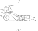
- Fig. 4 is a schematic view of an example of the leg/foot detection sensor 630.
- the leg/foot detection sensor 630 may be mounted on the frame 213.
- the foot detection sensor 630 may be an image sensor, an infrared sensor, or the like.
- the foot detection sensor 630 can detect behavior of a user's foot by measuring a distance from a foot of the user of the power-assisted rollator 100.
- the leg/foot detection sensor 630 shown in Fig. 4 may determine whether the user's foot in the area 630AR is moving, stays still, or moving closer/away, or the user is turning his/her back and about to sit on a seat 270.
- the ground sensor 640 may be provided on an axle of the pair of front wheels 220 and the pair of rear wheels 230. More specifically, the ground sensor 640 may detect whether each wheel touches the ground or not.
- the ground sensor 640 at the front wheels are in an OFF state and an inclined state of the rollator are detected from the signal from the above-described gyro sensor 620.
- Figs. 5 and 6 are schematic views for explaining the operating force sensor 650.
- the operating force sensor 650 may be provided on the grips 243, 244 of the pair of handles 240 to detect a pushing/pulling force of a user who is pushing or pulling the power-assisted rollator 100. Displacement of the operating force sensor 650 in the pushing and/or pulling direction with respect to the poles 241, 242 may be restricted by an elastic member such as a spring (not shown).
- the operating force sensor 650 may further include a potentiometer to detect the displacement.
- the pair of handles 240 may be disposed with an angle of ⁇ 1 in the downward direction with respect to the horizontal plane. Accordingly a user of the rollator can easily place his/her hands on the handles 240.
- the grips 243, 244 are movable in the front-rear direction with respect to the poles 241, 242.
- the grips When the grips are moved in the front direction indicated by the arrow in Fig. 6 , it may be determined that the power-assisted rollator 100 is pushed by a user.
- the grips When the grips are moved in the rear direction, it may be determined the power-assisted rollator 100 is pulled by the user.
- the grips are not moved, it may be determined that the rollator is neither pushed nor pulled.
- the user can easily operate the power-assisted rollator 100 since the user can operate the power-assisted rollator 100 in the same manner as a manual rollator.
- strain sensors 651, 652 may be provided on the grips 243, 244 to detect moments on the grips 243, 244 or the pair of pipe frames 211, 212, and the strain sensors may serve as the operating force sensor 650.
- the grips 243, 244 are fixed on the poles 241, 242 so that the structure becomes simple.
- a joy stick or a push button may be provided on the grips 243, 244 and these may be used as the operating force sensor 650.
- control unit 400 and the speed limiting unit 500 control the behavior of the motor 320 based on the detection signals from the speed detection sensor 610 and the operating force sensor 650.
- the motor 320 can be controlled based on the detection signals from the gyro sensor 620, the leg/foot detection sensor 630, and the ground sensors 640. More details will be hereunder described.
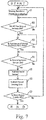
- Fig. 7 is a flowchart for explaining one example of the behavior of the control unit 400.
- control unit 400 may determine a received power from the battery 310 and display it on the display (step S1).
- step S2 it may be determined whether the ground sensors 640 at all of the wheels are ON state or not (step S2). When all the ground sensors 640 are not ON state, the control unit 400 waits until the ground sensors 640 at all of the wheels turn to ON state (No in the step S2).
- the leg/foot detection sensor 630 may determine whether a foot of a user exists within a predetermined area or not (step S3) after it is determined that the ground sensors 640 at all of the wheels become ON state (step S3).
- the control unit 400 waits until a leg/foot of the user is situated within the predetermined area (No in the step S3).
- the leg/foot detection sensor 630 determines that the user's leg/foot is situated within the predetermined area (Yes in the step S3), it may be determined whether the operating force sensor 650 is ON state or not (whether one or both of the grips 243, 244 is/are displaced in the pushing/pulling direction more than a predetermined amount of the displacement) (step S4).
- the control unit 400 waits until the operating force sensor 650 becomes ON state.
- control unit 400 drives (assist-control) the motor 320 in accordance with the ON state of the sensor (in accordance with the amount of the displacement of the grips 243, 244 in the pushing/pulling direction) (step S5).
- the assist control may be applied only when the rollator travels uphill instead of applying the assist control all the time. In this case, it is possible to save the battery while maintaining the usability of the rollator to a certain level.
- the control unit 400 may cause the speed limiting unit 500 to perform processing based on the detection states detected by each sensor (step S6).
- the speed limiting unit 500 may perform processing such that the power-assisted rollator 100 will not move at a speed exceeding a predetermined speed. For instance, the speed limiting unit 500 stops the driving of the motor 320, causes a dynamic braking or a regenerative braking on the motor, or causes a drive force of the motor in the opposite direction when a value of the speed detection sensor 610 exceeds a predetermined value.
- the control unit 400 may repeat the above-described process until the main power supply 480 is turned off (step S7).
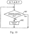
- Fig. 10 is a flowchart for explaining one example of the behavior of the speed limiting unit 500.
- Fig. 11 illustrates an example of characteristics of the speed limiting.
- the leg/foot detection sensor 630 is provided, the process of the flow chart shown in Fig. 8 is further performed.
- the gyro sensor 620 and the ground sensor 640 are provided, the processes of Figs. 12 and 13 are further performed.
- the speed limiting unit 500 may be configured to perform the processes concurrently.
- the speed limiting unit 500 may determine whether the leg/foot detection sensor 630 detects a leg/foot of a user within a predetermined area or not (step S21).
- leg/foot of the user who stretches his/her arms to the handles is situated between the pair of rear wheels 230 or within 50 cm distance from the rear wheels 230 in the backward direction.
- step S22 When it is determined that the leg/foot detection sensor 630 detected the leg/foot (Yes in the step S21), whether the leg/foot of the user is moving or not is determined (step S22). When it is determined that the leg/foot of the user stays still (No in the step S22), the speed limiting unit 500 halts or puts brakes on the operation of the motor 320 (step S23).
- step S24 it is determined whether a leg/foot is detected or not (step S24).
- the speed limiting unit 500 may cause the motor 320 to reverse by a certain amount, for example, 20 cm (step S25).
- the speed limiting unit 500 does not perform the process and goes back to the step S21.
- the speed limiting unit 500 goes back to the step S21 without performing the steps S23-S25 and repeats the above-described process.
- leg/foot detection sensor 630 detects that the detected foot of the user is a heel
- the rotation of the motor 320 may be stopped. This is because there is a possibility that the user turns his/her back and is about to sit on the seat of the power-assisted rollator 100.
- the speed limiting unit 500 may determine whether a switch for the main power supply 480 or the display 330 is turned ON or not (step S31).
- a stop process step step S32 is performed.
- the switch for the main power supply 480 is not turned ON, the motor is not driven so that the device is in a standby state until the switch for the main power supply 480 is turned ON.
- step S33 When the switch for the main power supply 480 or the display 330 is turned ON (Yes in the step S31), whether the operating force sensor 650 is ON or not (step S33) is determined. When it is determined that the operating force sensor 650 is OFF (No in the step S33), a drive instruction is not transmitted from the control unit 400 to the motor 320 but the speed limiting unit 500 controls the motor 320 to be excited so that the wheels will not be rotated (step S34). In this case, there is a possibility that the rollator is moving by an inertial force. Therefore when a value detected by the speed detection sensor 610 is equal to or smaller than a predetermined value, not a hard braking but a soft braking may be applied.
- step S36 When it is determined that the operating force sensor 650 is ON (Yes in the step S33), whether the ON state of the operating force sensor 650 is detected only on one side or only partially in the vertical direction is determined to perform a deceleration process (step S36).
- a driving amount of the motor 320 disposed in the right wheel may be increased or a driving amount of the motor 320 disposed in the left wheel may be decreased so that the rollator can turn left.
- a driving amount of the motor 320 disposed in the left wheel may be increased or a driving amount of the motor 320 disposed in the right wheel may be decreased so that the rollator can turn right.
- the operating force sensor 650 When the operating force sensor 650 is ON only partially in the vertical direction, the inclined state of the rollator is detected and the deceleration process may performed after the user's intention is confirmed.
- the speed limiting unit 500 may check the speed detection sensor 610 and determine whether the revolutions of the pair of front wheels 220/rear wheels 230 or the speed of the power-assisted rollator 100 is equal to or less than a predetermined value (step S41).
- the speed limiting unit 500 may not perform a process but the control unit 400 may perform the control.
- the speed limiting unit 500 may stop the assist control, halt driving of the motor 320, cause a dynamic braking or a regenerative braking, or cause a drive force of the motor in the opposite direction to perform the braking process (step S42).
- the vertical axis indicates a brake force or a braking load on the power-assisted rollator 100
- the horizontal axis indicates the number of revolutions of the wheel.
- the braking load when the number of revolutions of the wheel is equal to or smaller than a predetermined value, the braking load may remain at zero. But when the number of revolutions of the wheel exceeds the predetermined value, the braking load or the braking force may be set as indicated by the segment BP that increases in accordance with the number of revolutions of the wheel.
- the braking load is not limited to this. For instance, a constant braking load may be applied.
- the speed limiting unit 500 may control the motor 320 based on rotational acceleration or acceleration of the power-assisted rollator.
- the motor can be decelerated before the speed of the rollator increases so that the rollator can promptly slow down.
- it since it is not necessary to set the rollator to a reduced speed so that the usability will not be affected.
- the motor 320 may be reversed immediately after the power-assisted rollator 100 is stopped and then the power-assisted rollator 100 may be brought closer to the user by, for example, 20 cm. In this way, it is possible to promptly shorten the distance between the user and the power-assisted rollator 100 so that the user can restore a stable posture.
- the speed limiting unit 500 may check the attitude of the rollator by using the gyro sensor 620, and determine whether the power-assisted rollator 100 is on a flat ground or not (step S51). When it is determined that the power-assisted rollator 100 is on the flat ground (Yes in the step S51), the speed limiting unit 500 may not perform the process but the control unit 400 may perform the control.
- the speed limiting unit 500 determines whether the power-assisted rollator 100 is situated on an upward slope or not (step S52).
- the speed limiting unit 500 may not perform the process but the control unit 400 may perform the control.
- the control unit 400 may control to increase an amount of torque with its assisting function.
- the amount of torque may be increased in proportion to an amount of tilt detected by the gyro sensor 620.
- the predetermined value for the speed limiting unit 500 sets the number of revolutions of the wheels or the speed of the power-assisted rollator 100 shown in Fig. 11 to a lower value, thereby the braking load is applied at a speed lower than that of the flat ground (step S53).
- the speed limiting unit 500 may determine whether all the wheels (the pair of front wheels 220 and the pair of rear wheels 230) touch the ground or not by using the ground sensors 640 (step S61). When it is determined that all of the wheels touch the ground (Yes in the step S61), the processes described above with reference to Figs. 8-10 and 12 may be performed (step S62).
- step S63 determines whether only the pair of rear wheels 230 touches the ground.
- the speed limiting unit 500 performs an alarm process to trigger the alarm device 670 (step S64).
- the above detection result indicates that the wheels on only one side, only any one of the wheels, or only the pair of front wheels 220 is/are lifted from the ground so that the user is alerted.
- the alarm device 670 may be any device such as a display. a buzzer that makes an alarm sound, and a vibrator that imparts vibration on the grips 243, 244.
- the speed limiting unit 500 detects the attitude of the rollator by using the gyro sensor 620 and determine whether the detected value is equal to or smaller than a predetermined value (step S65).
- step S65 When the detected attitude using the gyro sensor 620 is within a predetermined range (Yes in the step S65), a braking process is applied by controlling the motor 320 (step S66).
- step S67 the motor 320 is reversed (step S67).
- a load can be applied so as to prevent the pair of front wheels 220 from lifting further from the ground.
- the motor may be controlled to reverse in order to bring the pair of front wheels 220 down to the ground.
- Fig. 14 is a schematic perspective view of a power-assisted rollator 100a according to the second embodiment, showing its major structural components.
- the power-assisted rollator 100a may include a limiting brake unit 700 instead of the speed limiting unit 500 in the power-assisted rollator 100 of the first embodiment.
- the limiting brake unit 700 may have the same braking characteristics as that of Fig. 11 and may be a centrifugal brake. In this case, the limiting brake unit 700 may be provided at least in the pair of rear wheels 230. For instance, the limiting brake unit 700 may be provided within the pair of rear wheels 230.
- the limiting brake unit 700 may be provided in the pair of front wheels 220 instead of the pair of rear wheels 230.
- the speed can be mechanically reduced so that the power of the power-assisted rollator 100a is not consumed by the speed limiting unit 500.
- a switch may be provided for adjusting the braking characteristics externally and thereby the adjustment of the speed limiting can be performed mechanically. Moreover, since electric power is not used to put brakes, the power can be saved and it is possible to extend a duration of the assist control.
- the braking is performed by only the limiting brake unit 700 in the second embodiment, this is not limited.
- a dynamic braking, a regenerative braking, or a drive force of the motor 320 generated in the opposite direction to the traveling direction may also be used in addition to the limiting brake unit 700. In this case, it is possible to reduce the size of the limiting brake unit 700 and to save the battery.
- Figs. 15 and 16 are schematic perspective views of a power-assisted rollator 100b according to the third embodiment.
- the power-assisted rollator 100b may have a structure that can be elongated and contracted in the front-rear direction of the power-assisted rollator 100b. This structure will be described in detail below.
- the power-assisted rollator 100b may include a horseshoe-like member 240b provided on the pair of handles 240.
- a pipe frame 241b may be formed so as to be connected with the pair of handles.
- the horseshoe-like member 240b and the pipe frame 241b may be configured to be turnable with respect to a pair of pipe frames 211b, 212b.
- a lock (not shown) for the turning of the horseshoe-like member 240b and the pipe frame 241b may be also provided.
- the seat 251b may be configured to be flipped up as illustrated in Figs. 15 and 16 .
- Frames 541, 543 may be provided such that they extend in the horizontal direction with respect to the pair of pipe frames 211b, 212b.
- a frame 571 may extend obliquely downward from the frame 541.
- Members 551, 552 that can be folded may be extended from the frame 543 and connected to the center of the frame 571.
- the power-assisted rollator 100b becomes in a usable state for a user as shown in Fig. 15 .
- the power-assisted rollator 100b becomes in a folded state to be stored as illustrated in Fig. 16 .
- a storage 271b may be provided under the seat 251b of the power-assisted rollator 100b.
- a substrate unit 592 which may include the control unit 400, the speed limiting unit 500 and the like may be provided in a portion of the storage 271b.
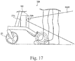
- Fig. 17 is a schematic view of another example of the leg/foot detection sensor 630 of Fig. 4 .
- a leg/foot detection sensor 630b may be mounted on the substrate unit 592 in the storage 271b. Like the leg/foot detection sensor 630, the leg/foot detection sensor 630b may be an image sensor, an infrared sensor, or the like.
- the leg detection sensor 630b can detect behavior of user's legs by measuring distances from right and left legs of the user of the power-assisted rollator 100b.
- the leg/foot detection sensor 630b shown in Fig. 17 may determine whether the user's leg within the area 630BR is moving, stays still, or moving closer/away, or the user is turning his/her back and about to sit on the seat 251b.
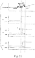
- Figs. 18-21 are schematic illustrations for control examples of the control unit 400.
- the drawing (a) in each of Figs. 18-21 illustrates an actual state of a slop and a flat ground.
- the drawing (b) in each of Figs. 18-21 illustrates an example of an amount of assist from the control unit 400 to the motor according to the conventional device.
- the drawing (c) in each of Figs. 18-21 illustrates an example of an amount of assist from the control unit 400 to the motor according to the embodiment.
- the drawing (d) in each of Figs. 18-21 illustrates another example of the amount of assist from the control unit 400 to the motor according to the embodiment.
- the limiting brake unit 700 may be used.
- the amount of assist gradually transitions (indicated by "CU") from positive to negative, subsequently overshot (indicated by "OS”) and then settled to a predetermined negative value as illustrated in Fig. 18(c) .
- the amount of assist is gradually transitioned (indicated by "CU") from a positive value to a negative value as illustrated in Fig. 18(d) .
- the amount of assist gradually transitions (indicated by "CU") from a positive value to a smaller positive value, subsequently overshot (indicated by "OS”) and then settled to a predetermined small value as illustrated in Fig. 19(c) .
- the amount of assist gradually transitions (indicated by "CU") from a positive value to a smaller positive value as illustrated in Fig. 19(d) .
- the amount of assist gradually transitions (indicated by "CU") from a negative value to a positive value, subsequently overshot (indicated by "OS”) and then settled to a predetermined positive value as illustrated in Fig. 20(c) .
- the amount of assist is gradually transitioned (indicated by "CU") from a negative value to a positive value as illustrated in Fig. 20(d) .
- the amount of assist gradually transitions (indicated by "CU") from a small positive value to a large positive value, subsequently overshot (indicated by "OS”) and then settled to a predetermined large positive value as illustrated in Fig. 21(c) .
- the amount of assist gradually transitions (indicated by "CU") from a small positive value to a large positive value as illustrated in Fig. 21(d) .
- the amount of assist generated by the motor 320 is not sharply changed but gradually transitions (CU) so that it is possible to prevent the power-assisted rollator 100b from leaving the user behind.
- the revolutions of the pair of rear wheels 230 are assist-controlled to facilitate the gait of the user.
- the revolutions of the rear wheels 230 can be reduced so that revolutions of the front wheels 220 and the rear wheels 230 immediately before the user falls can be controlled. Consequently it is possible to prevent the user from actually falling over.
- the motor 320 can be reduced automatically by the speed limiting unit 500 or by the limiting brake unit 700. Therefore, it is possible to prevent the power-assisted rollator 100, 100a, 100b from leaving the user behind and consequently the user is less likely to fall.
- the leg/foot detection sensor 630 and the leg/foot detection sensor 630b can detect the movements/distance of foot (feet)/leg(s) of the user and then the revolution of the pair of rear wheels 230 is controlled. Therefore, the revolution of the pair of wheels 230 can be stopped. Furthermore, when the distance from the rollator to the foot/leg of the user is increased, the revolution of the pair of rear wheels 230 can be stopped or reversed to prevent the user from falling over.
- the attitude of the power-assisted rollator 100, 100a, 100b is detected by using the gyro sensor 620 and thereby it is possible to determine that the rollator is situated on an upward slope, a flat ground, or a downward slope as well as controlling the pair of front wheels 220 and/or the pair of rear wheels 230 to obtain an adequate revolution of the wheels.
- each of the four wheels of the rollator touches the ground by the ground sensors 640. Accordingly it is possible to determine that the rollator 100, 100a, 100b is situated on steps, only the pair of rear wheels 230, only the pair of front wheels 220, only the right wheels, or only the left wheels touch the ground. Therefore, the rotational acceleration of the pair of front wheels 220 and the pair of rear wheels 230 can be controlled.
- the speed limiting unit 500 controlled the motor 320 based on the revolutions of the pair of rear wheels 230 or the speed of the power-assisted rollator.
- the motor 320 may be controlled based on the rotational acceleration of the rear wheels 230 and /or the front wheels 220 or the acceleration of the power-assisted rollator 100, 100a, 100b.
- the motor can be decelerated before the speed of the rollator increases so that the rollator can promptly slow down. Moreover, since it is not necessary to set the rollator to a reduced speed so that the usability will not be affected. Furthermore, by combining the limitations based on the speed and the acceleration, it is possible to satisfy both the usability and safety at a high level.
- the pair of rear wheels 230 have been illustrated but the embodiments are not limited to this.
- any continuous track such as a track shoe, a caterpillar and the like that surrounds a drive wheel, a track roller, an idling (idle) wheel, and a vertical trunk roller may be used.
- the pole-like handle or the horseshoe-like handle have been described as the pair of handles 240.
- both the pole-like handle (extending in the horizontal direction or the vertical direction) and the horseshoe-like handle may be provided to the rollator.
- a user can choose one of the two handle types which the user prefers.
- the embodiments are not limited to this.
- the embodiments may also include a walker and the like.
- the motor 320 corresponds to a "motor”
- the control unit 400 corresponds to a “control unit”
- the pair of rear wheels 230 corresponds to “wheels or continuous track”
- the speed limiting unit 500 corresponds to a "speed limiting unit”
- the limiting brake unit 700 corresponds to a “centrifugal brake”
- the power-assisted rollator 100, 100a, 100b corresponds to an "electric walking assistance device”
- the speed detection sensor 610 corresponds to a " speed detector”
- the seat 251b corresponds to a "seat”
- the storage 271 corresponds to a "storage”
- the leg/foot detection sensor 630, 630b corresponds to a " leg movement detector”
- the gyro sensor 620 corresponds to an "attitude detection sensor”
- the ground sensor 640 corresponds to a “ground sensor”
- the operating force sensor 650 corresponds to an “operating force sensor”
- the handle 240 corresponds to a “handle
Landscapes
- Health & Medical Sciences (AREA)
- General Health & Medical Sciences (AREA)
- Gerontology & Geriatric Medicine (AREA)
- Business, Economics & Management (AREA)
- Emergency Management (AREA)
- Physics & Mathematics (AREA)
- General Physics & Mathematics (AREA)
- Epidemiology (AREA)
- Pain & Pain Management (AREA)
- Physical Education & Sports Medicine (AREA)
- Rehabilitation Therapy (AREA)
- Life Sciences & Earth Sciences (AREA)
- Animal Behavior & Ethology (AREA)
- Public Health (AREA)
- Veterinary Medicine (AREA)
- Rehabilitation Tools (AREA)
Description
- The present invention relates to an electric walking assistance device according to the preamble of
independent claim 1. Such a device can be taken from the prior art documentKR 2011 0039617 A - Walking aids including a wheeled walker (a rollator, a rolling walker) that assists the elderly's outing, and a walker that assists disabled people or patients to gait have been used. For instance, Patent Literature 1 (Japanese Patent Application Publication
2009-183407 - The walking aid device disclosed in Patent Literature 1 (Japanese Patent Application Publication
2009-183407 - Patent Literature 2 (Japanese Patent
Hei 8-280763 - In the motor-driven four-wheel handcart disclosed in Patent Literature 2 (Japanese Patent
Hei 8-280763 - Patent Literature 3 (Japanese Patent Application Publication
Hei 11-267162 - The rollator disclosed in the Patent Literature 3 (Japanese Patent Application Publication
Hei 11-267162 -
- Patent Literature 1: Japanese Patent Application Publication No.
2009-183407 - Patent Literature 2: Japanese Patent Application Publication No.
Hei 8-280763 - Patent Literature 3: Japanese Patent Application Publication
Hei 11-267162 - In the field of the walking assistance device, it is well-known that the wheel drive is adjusted in accordance with the human power added thereto like the walking aid device disclosed in
Patent Literature 1. -
Patent Literature 2 disclosed that the motor-driven four-wheel handcart is stopped when either one or both of the hand-pushing sensing switches disposed at the handle is turned on/off (see paragraph 0006 of Patent Literature 2).Patent Literature 3 also disclosed that a photoelectric switch of the electric-motor equipped rollator is turned off when a user loses his/her grip from a handle, and the rotation of the motor is stopped while the clutch is working. Consequently a reducer serves as brakes even when the rollator travels downhill and the rollator can be remained standstill (see paragraph 0011 of Patent Literature 3). - However, when the elderlies use such walking assistance devices, they sometime fall as they are still holding the handle of the walking assistance device. In this case, only with the detection means provided at the handle, it is not possible to determine that the walking assistance device should be brought to a halt, and therefore it is not possible to prevent the user from falling down.
- One object of the invention is to provide an electric walking assistance device with which it is possible to prevent an elderly user who is holding a handle of the device and about to fall from actually falling down, and to provide a program and method for controlling the electric walking assistance device.
- According to the present invention said object is solved by An electric walking assistance device having the features of
independent claim 1 and a program for controlling an electric walking assistance device having the features of independent claim 18 and a method for controlling an electric walking assistance device having the features of independent claim 19. Preferred embodiments are laid down in the dependent claims. - [1] According to one aspect of the invention, an electric walking assistance device is a walking assistance device that has wheels or a continuous track. The electric walking assistance device includes a motor that drives the wheels or the continuous track, a control unit that controls the motor in accordance with an operating force applied to the walking assistance device by a user, and a speed limiting unit that limits revolutions of the wheels or the continuous track when it is determined that the revolutions of the wheels or the continuous track or a speed of the electric walking assistance device is equal to or larger than a predetermined value.
- In the electric walking assistance device according to one aspect of the invention, revolutions of the wheels or the continuous track is controlled in accordance with an operating force (generally, a pushing and pulling force) applied to the walking assistance device by a user (this control may be hereunder referred to as an "assist control"). A resultant force in which the operating force and the rotational force of the wheels are combined makes it possible for the user to walk as utilizing the user's ability even when the user walks on a slope, a rough road or other disadvantageous factors for walking. Moreover, the number of the revolutions of the wheels or the continuous track is limited when it is determined that the revolutions of the wheels or the continuous track or a speed of the electric walking assistance device is equal to or larger than a predetermined value. In other words, an increase in the revolutions of the wheels or the continuous track or the speed of the electric walking assistance device just before a user falls is detected to limit the revolutions of the wheels so that it is possible to prevent the user from actually falling.
Here, the revolutions of the wheels or the continuous track encompasses an angular acceleration of the wheels, an angular velocity of the wheels, and the number of revolutions of the wheels per unit hour. The speed of the walking assistance device encompasses a velocity and an acceleration of the walking assistance device. - The control unit of the power-assisted rollator may turn OFF the assist control and put the rollator in a free state (no load on the wheels) when the speed of the rollator or the number of revolutions of the wheels exceeds a predetermined value. Furthermore, the control unit of the power-assisted rollator may turn ON the assist control to resume the operation when the speed of the rollator or the number of revolutions of the wheels falls below a predetermined value.
- The control unit of the power-assisted rollator may put a weak brake through the assist control when the speed of the wheels is further increased. The control unit may set a certain hysteresis such that the speed of the wheel is reduced to below the predetermined value. In this way, turning ON/OFF of the brakes will not be frequently repeated.
The control unit may put a hard brake when the speed is further increased. In this case, the speed of the electric walking assistance device becomes substantially zero.
However, if the control unit suddenly lifts the brake in response to the detected speed, the rollator may perform off-and-on behavior such that the rollator is accelerated again with an unstable attitude such as fall. Therefore, once a hard brake is applied, release of the brake should be triggered by other signal indicating that the user for example, a user released his/her hand from the device, the user's body is situated close to the device or the like. - [2] According to a second aspect of the invention, when the number of rotations of the motor is equal to or larger than a predetermined value, the speed limiting unit may cause a torque to be generated in the motor to reduce the number of rotations of the motor to less than a predetermined value.
In this case, it becomes possible to easily set any number of rotations of the motor. In other words, the number of rotations of the motor can be set in accordance with a walking capability of the user so that it is possible to prevent the fall of the user from occurring.
Here, setting any number of rotations of the motor means that a "fall" is detected through an acceleration of the walking assistance device. More specifically, a turnover force generated when the rollator falls have a front-downward direction vector. The electric walking assistance device is generally accelerated in parallel to the ground surface.
In other words, the cosine of the turnover force and the slope of the ground can be detected as the acceleration. Therefore, the acceleration at the time of turnover on the upward slope is detected smaller than that on the flat ground. Consequently if a threshold value of the revolutions is set equally for the flat ground and the upward slope, the turnover on the upward slope will be less sensitive to the sensor. By correcting the threshold depending on a slope, this problem can be solved. - [3] According to a third aspect of the invention, in the electric walking assistance device according to the first and second aspects, when an acceleration of the walking assistance device is equal to or larger than a predetermined value, the control unit may stop the rotations of the motor or reverse the motor by a prescribed amount.
In this case, the rotation of the motor is stopped when the acceleration exceeds the predetermined value, so that it is possible to at least prevent the electric walking assistance device from leaving the user behind. Moreover even if the electric walking assistance device temporarily moves away from a position where the user can easily operate the walking assistance device, it is possible to bring the walking assistance device back to the position by reversing the motor by a prescribed amount. In this way, it is possible to effectively prevent the fall of the user. - [4] According to a fourth aspect of the invention, the electric walking assistance device according to the first to third aspects may further include a leg movement detector sensing a back side of the electric walking assistance device, wherein the control unit controls the rotations of the motor depending on a sensing result of the leg movement detector.
In this case, the movements/distance of foot (feet)/leg(s) of the user is detected and then the rotations of the motor is controlled. Therefore, when the leg or foot of the user stops, the rotation of the motor can be stopped. Furthermore, when the distance from the rollator to the foot/leg of the user is increased, the rotation of the motor can be stopped or reversed to prevent the user from falling over.
Note that the all of the legs of the user may be detected. For instance, each knee of the user may be detected by a respective leg movement detector. - [5] According to a fifth aspect of the invention, the electric walking assistance device according to the second to fourth aspects may further include an attitude detection sensor detecting an attitude of the electric walking assistance device, wherein the control unit controls the rotations of the motor depending on a detection result of the attitude detection sensor.
In this case, it is possible to determine that the rollator is situated on an upward slope, a flat ground, or a downward slope by detecting an attitude of the walking assistance device. Moreover it is possible to control the wheels or the continuous track to obtain an adequate revolution. In this way, it is possible to maintain a constant relationship between the user and the walking assistance device, for example, a constant distance therebetween, so that it is possible to prevent the user from falling. - [6] According to a sixth aspect of the invention, the electric walking assistance device according to the second to fifth aspects may further include a ground sensor detecting whether the wheels or the continuous track touches the ground, wherein the control unit controls the rotations of the motor depending on a detection result of the ground sensor.
In this case, it is possible to determine whether the wheels or the continuous track of the electric walking assistance device touches the ground or not by the ground sensor. Accordingly, it is possible to whether the walking assistance device is situated at a place having steps such as stairs. Therefore the rotation of the motor can be controlled in accordance with a use state of the walking assistance device by the user. In this way, it is possible to effectively prevent the fall of the user. - [7] According to a seventh aspect of the invention, in the electric walking assistance device according to the second to sixth aspects, when the attitude detection sensor detects that an attitude of the electric walking assistance device is changed from a horizontal state to a downwardly inclined state, the rotations of the motor is reduced from a normal state or reversed by a predetermined amount.
When the electric walking assistance device according to this aspect is inclined downwardly from the horizontal state, the rotation of the motor is reduced gradually or in a step-by-step manner or reversed by a predetermined amount to prevent the electric walking assistance device from leaving the user behind. Therefore the user can use the electric walking assistance device reliably when the user starts walking on a downward slope. In this way, it is possible to effectively prevent the fall of the user.
Here, the normal state means the rotation state of the power-assisted motor when the electric walking assistance device is in the horizontal state. - [8] According to an eighth aspect of the invention, in the electric walking assistance device according to the second to sixth aspects, when the attitude detection sensor detects that an attitude of the electric walking assistance device is changed from a forward tilting state (the downward inclined state) to the horizontal state, the rotations of the motor may be increased from a reduced state to the normal state.
When the attitude of the electric walking assistance device according to this aspect is changed from the forward tilting state (the downward inclined state) to the horizontal state, the rotation of the motor is increased gradually or in a step-by-step manner to prevent the electric walking assistance device from being brought too close to the user. Therefore the user can use the electric walking assistance device reliably when the user walking from the downward slope to a flat ground. In this way, it is possible to effectively prevent the fall of the user. - [9] According to a ninth aspect of the invention, in the electric walking assistance device according to the second to eighth aspects, when the attitude detection sensor detects that an attitude of the electric walking assistance device is changed from the horizontal state to a backward tilting state (an upward inclined state), the rotations of the motor may be increased from the normal state.
When the attitude of the electric walking assistance device according to this aspect is changed from the horizontal state to the backward tilting state (the upward inclined state), the rotation of the motor is increased gradually or in a step-by-step manner to prevent the electric walking assistance device from slipping down on the slope toward the user. Therefore the user can use the electric walking assistance device reliably when the user starts walking on the upward slope. In this way, it is possible to effectively prevent the fall of the user. - [10] According to a tenth aspect of the invention, in the electric walking assistance device according to the second to ninth aspects, when the attitude detection sensor detects that an attitude of the electric walking assistance device is changed from the backward tilting state (the upward inclined state) to the horizontal state, the rotations of the motor may be reduced from the increased state.
When the attitude of the electric walking assistance device according to this aspect is changed from the backward tilting state (the upward inclined state) to the horizontal state, the rotation of the motor is decreased gradually or in a step-by-step manner to prevent the electric walking assistance device from leaving the user behind. Therefore the user can use the electric walking assistance device reliably when the user starts walking on the flat ground. In this way, it is possible to effectively prevent the fall of the user. - [11] According to an eleventh aspect of the invention, the electric walking assistance device according to the second to tenth aspects may further include a handle coupled to the frame, and the handle may have an operating force sensor.
In this case, it is possible to determine whether a user tries to operate the electric walking assistance device or not by the operating force sensor. Accordingly, when the user does not try to operate the electric walking assistance device, the revolutions of the wheels or the continuous track can be stopped. In this way, it is possible to effectively prevent the fall of the user. - [12] According to a twelfth aspect of the invention, in the electric walking assistance device according to the second to eleventh aspects, the handle may have a horseshoe shape.
Since the shape of the handle is a horseshoe shape on which the user can place his/her both elbows so that the user can easily operate the electric walking assistance device. In this way, it is possible to effectively prevent the fall of the user. Note that both the pole-like handle and the horseshoe-like handle may be provided to the electric walking assistance device. - [13] According to a thirteenth aspect of the invention, the electric walking assistance device according to the second to twelfth aspects may further include a handle coupled to the frame, and a connecting portion that couples the handle to the frame, wherein the handle extends from the connection portion in a horizontally downward direction.
In this case, since the handle extends from the connection portion of the frame in a horizontally downward direction so that it is possible to enhance the operability of the electric walking assistance device. In this way, it is possible to effectively prevent the fall of the user. - [14] According to a fourteenth aspect of the invention, the electric walking assistance device according to the second to thirteenth aspects may further include a handle coupled to the frame, and the handle extends in one direction and has a movable grip, wherein the rotations of the motor may be controlled depending on a position of the grip.
In this case, when the grip is moved forward, the user intends to travel forward so that the rotation of the motor is power assisted. Whereas when the grip is moved backward, the user intends to stop using the electric walking assistance device so that the rotation of the motor may be stopped. According to this operation method, the user's intention can be easily reflected to the electric walking assistance device and the user less likely to make an operation mistake. Therefore, it is possible to effectively prevent the fall of the user. - [15] According to a fifteenth aspect of the invention, in the electric walking assistance device according to the first to fourteenth aspects, the handle has a flip-up mechanism, and when the handle is flipped up, the control unit may stop the rotations of the motor to stop the wheels or the continuous track.
When the handle is flipped up, the rotation of the motor is stopped and thereby the wheels or the continuous track is stopped. When the handle is flipped up by a user, the user intends to stop walking so that it is preferable that the wheels or the continuous track is stopped. In this way, the electric walking assistance device will not move involuntarily so that it is possible to effectively prevent the user from falling. - [16] According to a sixteenth aspect of the invention, the electric walking assistance device according to the first to fifteenth aspects may further include a storage disposed below a handle and above the wheels or the continuous track, wherein the control unit may be disposed in a part of the storage.
Since the storage is disposed below a handle and above the wheels or the continuous track, the stability of the electric walking assistance device will be maintained even when the storage stores something therein. In this way, it is possible to effectively prevent the fall of the user. Moreover, since the control unit is disposed in a portion of the storage, wirings extending from the control unit to the wheels can be made short. - [17] According to a seventeenth aspect of the invention, in the electric walking assistance device, the speed limiting unit may include a centrifugal brake disposed within the wheels or a driving wheel of the continuous track.
Since a mechanical centrifugal brake is provided inside the wheels or the driving wheel of the continuous track, electric power is not used to put brakes. Therefore the power can be saved and it is possible to extend a duration of the assist control. Moreover, adjustment of the speed limiting can be mechanically performed. In this way, it is possible to prevent the fall of the user from actually occurring. - [18] According to another aspect of the invention, provided is a program for controlling an electric walking assistance device. The program may include rotating a motor that drives wheels or a continuous track in accordance with a human power applied to the electric walking assistance device by a user; determining whether revolutions of the wheels or the continuous track or a speed of the electric walking assistance device is equal to or larger than a predetermined value; and limiting the revolutions of the wheels or the continuous track when it is determined that the revolutions or the speed of the electric walking assistance device is equal to or larger than the predetermined value.
The revolution of the wheels or the continuous track is controlled in accordance with the operating force applied to the walking assistance device by the user. A resultant force in which the operating force and the rotational force of the wheels are combined makes it possible for the user to walk as utilizing the user's ability even when the user walks on a slope, a rough road or other disadvantageous factors for walking. Moreover, whether the revolutions of the wheels or the continuous track or a speed of the electric walking assistance device is equal to or larger than a predetermined value is determined. When it is, the revolutions of the wheels are limited. In other words, an increase in the revolutions of the wheels or the continuous track or the speed of the electric walking assistance device just before a user falls is detected to limit the revolutions of the wheels or the continuous track so that it is possible to prevent the user from actually falling.
Here, the revolutions of the wheels or the continuous track encompasses an angular acceleration of the wheels, an angular velocity of the wheels, and the number of revolutions of the wheels per unit hour. The speed of the walking assistance device encompasses a velocity and an acceleration of the walking assistance device. - [19] According to another aspect of the invention, provided is a method for controlling an electric walking assistance device. The method may include: rotating a motor that drives wheels or a continuous track in accordance with a human power applied to the electric walking assistance device by a user; determining whether revolutions of the wheels or the continuous track or a speed of the electric walking assistance device is equal to or larger than a predetermined value; and limiting the revolutions of the wheels or the continuous track when it is determined that the revolutions or the speed of the electric walking assistance device is equal to or larger than the predetermined value.
- The revolution of the wheels or the continuous track is controlled in accordance with the operating force applied to the walking assistance device by the user. A resultant force in which the operating force and the rotational force of the wheels are combined makes it possible for the user to walk as utilizing the user's ability even when the user walks on a slope, a rough road or other disadvantageous factors for walking. Moreover, whether the revolutions of the wheels or the continuous track or a speed of the electric walking assistance device is equal to or larger than a predetermined value is determined. When it is, the revolutions of the wheels or the continuous track are limited. In other words, an increase in the revolutions of the wheels or the continuous track or the speed of the electric walking assistance device just before a user falls is detected to limit the revolutions of the wheels or the continuous track so that it is possible to prevent the user from actually falling.
Here, the revolutions of the wheels or the continuous track encompasses an angular acceleration of the wheels, an angular velocity of the wheels, and the number of revolutions of the wheels per unit hour. The speed of the walking assistance device encompasses a velocity and an acceleration of the walking assistance device. -
-
Fig. 1 is a schematic perspective view of a power-assisted rollator according to a first embodiment, showing its appearance. -
Fig. 2 is a side view of the power-assisted rollator ofFig. 1 . -
Fig. 3 is a schematic view of the power-assisted rollator showing its major internal structural components. -
Fig. 4 is a schematic view of an example of a leg/foot detection sensor. -
Fig. 5 is a schematic view for explaining an operating force sensor. -
Fig. 6 is a schematic view for explaining the operating force sensor. -
Fig. 7 is a flowchart for explaining one example of the behavior of a control unit. -
Fig. 8 is a flowchart for explaining one example of the behavior of a speed limiting unit. -
Fig. 9 is a flowchart for explaining one example of the behavior of the speed limiting unit. -
Fig. 10 is a flowchart for explaining one example of the behavior of the speed limiting unit. -
Fig. 11 illustrates an example of characteristics of the speed limiting. -
Fig. 12 is a flowchart for explaining one example of the behavior of the speed limiting unit. -
Fig. 13 is a flowchart for explaining one example of the behavior of the speed limiting unit. -
Fig. 14 is a schematic perspective view of a power-assisted rollator according to a second embodiment, showing its major structural components. -
Fig. 15 is a schematic perspective view of a power-assisted rollator according to a third embodiment. -
Fig. 16 is a schematic perspective view of the power-assisted rollator according to the third embodiment. -
Fig. 17 is a schematic view of another example of the leg/foot detection sensor ofFig. 4 . -
Fig. 18 is a schematic illustration for a control example of a control unit. -
Fig. 19 is a schematic illustration for a control example of the control unit. -
Fig. 20 is a schematic illustration for a control example of the control unit. -
Fig. 21 is a schematic illustration for a control example of the control unit. -
- 100, 100a, 100b
- power-assisted rollator
- 210
- frame
- 220
- front wheels
- 230
- rear wheels
- 240
- handle
- 250
- brake unit
- 251b
- seat
- 260
- fall prevention member
- 271b
- storage
- 310
- battery
- 320
- motor
- 400
- control unit
- 500
- speed limiting unit
- 592
- substrate unit
- 610
- speed detection sensor
- 620
- gyro sensor
- 630, 630b
- leg/foot detection sensor
- 640
- ground sensor
- 650
- operating force sensor
- 670
- alarm device
- 700
- control brake unit
- Embodiment of the present invention will be now described with reference to the accompanying drawings. In the following description, like elements may be numbered and labeled similarly. Functions of the like elements are also same so that descriptions of such elements will be hereunder omitted.
- An electric rollator (hereunder referred to as a power-assisted rollator) is now described as an example of a walking assistance device.
Fig. 1 is a schematic perspective view of a power-assistedrollator 100 according to the first embodiment, showing its appearance.Fig. 2 is a side view of the power-assistedrollator 100 ofFig. 1 , andFig. 3 is a schematic view of the power-assistedrollator 100 showing its major internal structural components. - Referring to
Figs. 1-3 , the power-assistedrollator 100 may include aframe 210, a pair offront wheels 220, a pair ofrear wheels 230, a pair ofhandles 240, abrake unit 250, and afall prevention member 260. - The power-assisted
rollator 100 may further include abattery 310,motors 320, adisplay 330, acontrol unit 400, amain power supply 480, aspeed limiting unit 500, aspeed detection sensor 610, agyro sensor 620, a leg/foot detection sensor 630, aground sensor 640, an operatingforce sensor 650, and analarm device 670. - Note that the
display 330, thegyro sensor 620, the leg/foot detection sensor 630, theground sensor 640, and thealarm device 670 may be omitted as appropriate. - Referring to
Figs. 1 and2 , theframe 210 may include a left-right pair of pipe frames 211, 212, and aframe 213 that couples the pair of pipe frames 211, 212. - On front ends of the pipe frames 211, 212, a pair of
wheels front wheels 220, may be provided respectively. Thewheels wheel pair 220 may be configured to wheel in a front-rear direction and also rotate about a vertical axis. - On rear ends of the pipe frames 211, 212, a pair of
wheels rear wheels 230, may be provided respectively. - The
wheels 231, 332 may be configured to wheel in the front-rear direction. - Accordingly, the power-assisted
rollator 100 can be easily moved forward and backward, moreover, can be easily maneuvered in a left-right direction or easily turn around. -
Brake shoes 255, 256 may be provided on the periphery of thewheels wheels brake shoes 255, 256 may be coupled to brakelevers brake unit 250 through wires 253, 254 respectively. Thebrake shoes 255, 256 are activated in accordance with operation of the brake levers 251, 252. The mechanical brakes are not limited to this but any mechanical brakes can be used. - The
fall prevention member 260 may be provided on the rear end of each of the pipe frames 211, 212. Thefall prevention member 260 is configured to prevent the power-assistedrollator 100 from being toppled in the rear direction when the pair offront wheel 220 is lifted off the ground. Note that other mechanism or structures may be used to prevent the rollator from falling instead of the above-describedfall prevention member 260. In this case, thefall prevention member 260 may be omitted. - On upper ends of the pipe frames 211, 212, a pair of
handles 240 may be provided. The pair ofhandles 240 may includepoles poles grips - Brake levers 241, 242 may be provided on the
poles - A
battery 310 may be fixedly provided on theframe 213 disposed between the pair of pipe frames 211, 212. Over thebattery 310, astorage 315 where an user can store his/her belongings may be provided. - In this embodiment, the
motor 320 is respectively provided inside the pair ofwheels rear wheels 230. - The
motor 320 may be any motor such as a servomotor, a stepper motor, an AC motor, and a DC motor. Moreover, a reducer can be integrated with the motor. - Although the
motor 320 is provided within each of thewheels motor 320 may be stored only within thewheels front wheel pair 220, or within all of the pair offront wheels 220 and the pair ofrear wheels 230. - The
control unit 400 and thespeed limiting unit 500 may be provided in proximity to thebattery 310. Details of thecontrol unit 400 and thespeed limiting unit 500 will be described below. - The
speed detection sensor 610 may be disposed in proximity to thecontrol unit 400 and thespeed limiting unit 500. Alternatively thespeed detection sensor 610 may be provided within each of thewheels rear wheel pair 230 of the power-assistedrollator 100. Alternatively, thespeed detection sensor 610 may be provided within each of thewheels front wheel pair 220 in the same manner as themotor 320, or within all of the pair offront wheels 220 and the pair ofrear wheels 230. - In this case, when the
motor 320 is a brushless motor, thespeed detection sensor 610 may be configured to calculate the number of revolutions or a speed of the wheel or a speed of the power-assistedrollator 100 using a hall element. - When the speed can be detected from a counter electromotive force of the
motor 320, the number of revolutions or a speed of the wheel or a speed of the power-assistedrollator 100 can be calculated from the counter electromotive force. When angular velocities of thewheels rear wheel pair 230 or thewheels front wheel pair 220 can be detected, the number of revolutions or a speed of the wheel or a speed of the power-assistedrollator 100 can be calculated from the angular velocities. - The
speed detection sensor 610 may be mounted to any of the components such as theframe 210 and the pair ofhandles 240, not limited to the pair of thefront wheels 220 and the pair of therear wheels 230. In this case, when the speed detection sensor is an acceleration detection sensor, the speed may be calculated by integrating acceleration components. When the speed detection sensor includes a global positioning system (GPS), the speed may be calculated by differentiating location information. - The
gyro sensor 620 may be provided in the upper portion of the power-assistedrollator 100, for example, inside the pair ofhandles 240. Alternatively thegyro sensor 620 may be provided in the lower portion of the power-assistedrollator 100. However, when thegyro sensor 620 is provided in the upper portion, it is possible to detect the attitude of the power-assistedrollator 100 more accurately. Note that the attitude of the power-assistedrollator 100 may be detected by a two or more-axis acceleration detection sensor instead of the gyro sensor. - The
control unit 400 of the power-assistedrollator 100 may turn OFF the power assist control and put the rollator in a free state (no load on the wheels) when the number of revolutions of thewheels - The
control unit 400 of the power-assistedrollator 100 may turn ON the power assist control and resume the power assist control when the number of revolutions of thewheels - The
control unit 400 of the power-assistedrollator 100 may control the assist control to put a weak brake on the rollator when the number of revolutions of thewheels - The
control unit 400 may set a certain hysteresis such that it may lift the brakes when the speed of the wheel is reduced to below a predetermined value. In this way, turning ON/OFF of the brakes will not be frequently repeated. In other words, only when the speed is reduced by a predetermined amount from the second predetermined value, the control unit releases the brake. - Moreover, the
control unit 400 may put a hard brake on the rollator when the number of revolutions of thewheels rollator 100 becomes substantially zero. - If the
control unit 400 suddenly lifts the brake in response to the detected speed, the rollator may perform off-and-on behavior such that the rollator is accelerated again with an unstable attitude including turnover. - To avoid this, after a hard brake is applied, the control unit lifts the brake in response to other signal indicating that, for example, an user released his/her hand from the
handle 240, the leg/foot detection sensor 630 detects that the user's body is situated close to the power-assistedrollator 100 or the like. - Moreover, the
control unit 400 of the power-assistedrollator 100 can set any number of revolutions of the wheel in order to prevent the fall of the rollator. - More specifically, a turnover force generated when the rollator falls have a front-downward direction vector. Acceleration of the electric walking assistance device works generally in parallel with the ground surface. More specifically, when a road is flat, the walking assistance device is accelerated in a horizontal direction and when a road is an upward slope, the walking assistance device is accelerated in parallel with the upward slope.
- In other words, the cosine of the turnover force and the slope of the ground can be detected as the acceleration.
- Therefore, the acceleration at the time of turnover on the upward slope is detected smaller than that of the flat ground. Consequently if a threshold value of the revolutions is set equally for the flat ground and the upward slope, the turnover on the upward slope will be less sensitive to the sensor. For this reason, the predetermined number of revolutions is set such that the threshold value is corrected in accordance with the slope in this embodiment.
-
Fig. 4 is a schematic view of an example of the leg/foot detection sensor 630. - Referring to
Fig. 4 , the leg/foot detection sensor 630 may be mounted on theframe 213. Thefoot detection sensor 630 may be an image sensor, an infrared sensor, or the like. - The
foot detection sensor 630 can detect behavior of a user's foot by measuring a distance from a foot of the user of the power-assistedrollator 100. - More specifically, the leg/
foot detection sensor 630 shown inFig. 4 may determine whether the user's foot in the area 630AR is moving, stays still, or moving closer/away, or the user is turning his/her back and about to sit on aseat 270. - The
ground sensor 640 may be provided on an axle of the pair offront wheels 220 and the pair ofrear wheels 230. More specifically, theground sensor 640 may detect whether each wheel touches the ground or not. - When the front wheels of the rollator are lifted up to climb over a step, the
ground sensor 640 at the front wheels are in an OFF state and an inclined state of the rollator are detected from the signal from the above-describedgyro sensor 620. - When the rollator moves on a slope, an inclined state is detected from a signal of the
gyro sensor 620 and theground sensors 640 in all the wheels are also in an ON state. In this way, it is possible to detect that the rollator is moving on the slope. -
Figs. 5 and6 are schematic views for explaining the operatingforce sensor 650. - The operating
force sensor 650 may be provided on thegrips handles 240 to detect a pushing/pulling force of a user who is pushing or pulling the power-assistedrollator 100. Displacement of the operatingforce sensor 650 in the pushing and/or pulling direction with respect to thepoles force sensor 650 may further include a potentiometer to detect the displacement. - The pair of
handles 240 may be disposed with an angle of θ1 in the downward direction with respect to the horizontal plane. Accordingly a user of the rollator can easily place his/her hands on thehandles 240. - As mentioned above, the
grips poles Fig. 6 , it may be determined that the power-assistedrollator 100 is pushed by a user. When the grips are moved in the rear direction, it may be determined the power-assistedrollator 100 is pulled by the user. When the grips are not moved, it may be determined that the rollator is neither pushed nor pulled. - In this manner, it is possible to determine that the user tries to move the power-assisted
rollator 100 forward or backward, or the user does not have the intention to change the state of the power-assistedrollator 100. - With this configuration, the user can easily operate the power-assisted
rollator 100 since the user can operate the power-assistedrollator 100 in the same manner as a manual rollator. - Referring again to
Fig. 6 ,strain sensors 651, 652 (for example, strain gauges) may be provided on thegrips grips force sensor 650. - In this case, the
grips poles - Alternatively, a joy stick or a push button may be provided on the
grips force sensor 650. - As described above, the
control unit 400 and thespeed limiting unit 500 control the behavior of themotor 320 based on the detection signals from thespeed detection sensor 610 and the operatingforce sensor 650. Moreover, themotor 320 can be controlled based on the detection signals from thegyro sensor 620, the leg/foot detection sensor 630, and theground sensors 640. More details will be hereunder described. -
Fig. 7 is a flowchart for explaining one example of the behavior of thecontrol unit 400. - Referring to
Fig. 7 , after themain power supply 480 is turned on, thecontrol unit 400 may determine a received power from thebattery 310 and display it on the display (step S1). - If the
ground sensors 640 are provided, it may be determined whether theground sensors 640 at all of the wheels are ON state or not (step S2). When all theground sensors 640 are not ON state, thecontrol unit 400 waits until theground sensors 640 at all of the wheels turn to ON state (No in the step S2). - If the leg/
foot detection sensor 630 is provided, the leg/foot detection sensor 630 may determine whether a foot of a user exists within a predetermined area or not (step S3) after it is determined that theground sensors 640 at all of the wheels become ON state (step S3). - When the leg/
foot detection sensor 630 determines that the user's leg/foot is not situated within the predetermined area, thecontrol unit 400 waits until a leg/foot of the user is situated within the predetermined area (No in the step S3). - Whereas when the leg/
foot detection sensor 630 determines that the user's leg/foot is situated within the predetermined area (Yes in the step S3), it may be determined whether the operatingforce sensor 650 is ON state or not (whether one or both of thegrips force sensor 650 is not ON state (No in the step S4), thecontrol unit 400 waits until the operatingforce sensor 650 becomes ON state. - When the operating
force sensor 650 is turned to ON state (Yes in the step S4), thecontrol unit 400 drives (assist-control) themotor 320 in accordance with the ON state of the sensor (in accordance with the amount of the displacement of thegrips - When the
gyro sensor 620 is provided, the assist control may be applied only when the rollator travels uphill instead of applying the assist control all the time. In this case, it is possible to save the battery while maintaining the usability of the rollator to a certain level. - The
control unit 400 may cause thespeed limiting unit 500 to perform processing based on the detection states detected by each sensor (step S6). Thespeed limiting unit 500 may perform processing such that the power-assistedrollator 100 will not move at a speed exceeding a predetermined speed. For instance, thespeed limiting unit 500 stops the driving of themotor 320, causes a dynamic braking or a regenerative braking on the motor, or causes a drive force of the motor in the opposite direction when a value of thespeed detection sensor 610 exceeds a predetermined value. - The
control unit 400 may repeat the above-described process until themain power supply 480 is turned off (step S7). -
Fig. 10 is a flowchart for explaining one example of the behavior of thespeed limiting unit 500.Fig. 11 illustrates an example of characteristics of the speed limiting. When the leg/foot detection sensor 630 is provided, the process of the flow chart shown inFig. 8 is further performed. When thegyro sensor 620 and theground sensor 640 are provided, the processes ofFigs. 12 and13 are further performed. Thespeed limiting unit 500 may be configured to perform the processes concurrently. - Referring to
Fig. 8 , thespeed limiting unit 500 may determine whether the leg/foot detection sensor 630 detects a leg/foot of a user within a predetermined area or not (step S21). - More specifically, it is determined whether the leg/foot of the user who stretches his/her arms to the handles is situated between the pair of
rear wheels 230 or within 50 cm distance from therear wheels 230 in the backward direction. - When the leg/foot of the user is not detected (No in the step S21), the
speed limiting unit 500 goes standby. - When it is determined that the leg/
foot detection sensor 630 detected the leg/foot (Yes in the step S21), whether the leg/foot of the user is moving or not is determined (step S22). When it is determined that the leg/foot of the user stays still (No in the step S22), thespeed limiting unit 500 halts or puts brakes on the operation of the motor 320 (step S23). - After the braking process, it is determined whether a leg/foot is detected or not (step S24). When no leg/foot of the user is detected (Yes in the step S24), the
speed limiting unit 500 may cause themotor 320 to reverse by a certain amount, for example, 20 cm (step S25). - When the leg/foot of the user is not detected (No in the step S24), the
speed limiting unit 500 does not perform the process and goes back to the step S21. - Whereas when it is determined that the leg/foot of the user is moving (Yes in the step S22), the
speed limiting unit 500 goes back to the step S21 without performing the steps S23-S25 and repeats the above-described process. - Although not shown in
Fig. 8 , note that when the leg/foot detection sensor 630 detects that the detected foot of the user is a heel, the rotation of themotor 320 may be stopped. This is because there is a possibility that the user turns his/her back and is about to sit on the seat of the power-assistedrollator 100. - Referring to
Fig. 9 , thespeed limiting unit 500 may determine whether a switch for themain power supply 480 or thedisplay 330 is turned ON or not (step S31). When the switch for themain power supply 480 or thedisplay 330 is not turned ON (No in the step S31), a stop process step (step S32) is performed. When the switch for themain power supply 480 is not turned ON, the motor is not driven so that the device is in a standby state until the switch for themain power supply 480 is turned ON. - When the switch for the
main power supply 480 or thedisplay 330 is turned ON (Yes in the step S31), whether the operatingforce sensor 650 is ON or not (step S33) is determined. When it is determined that the operatingforce sensor 650 is OFF (No in the step S33), a drive instruction is not transmitted from thecontrol unit 400 to themotor 320 but thespeed limiting unit 500 controls themotor 320 to be excited so that the wheels will not be rotated (step S34). In this case, there is a possibility that the rollator is moving by an inertial force. Therefore when a value detected by thespeed detection sensor 610 is equal to or smaller than a predetermined value, not a hard braking but a soft braking may be applied. - When it is determined that the operating
force sensor 650 is ON (Yes in the step S33), whether the ON state of the operatingforce sensor 650 is detected only on one side or only partially in the vertical direction is determined to perform a deceleration process (step S36). - In the deceleration process, for example, when the operating
force sensor 650 is ON only on one side (the right side) or an amount of the operation is larger in the right side, a driving amount of themotor 320 disposed in the right wheel may be increased or a driving amount of themotor 320 disposed in the left wheel may be decreased so that the rollator can turn left. Whereas when the operatingforce sensor 650 is ON only on the left side or an amount of the operation is larger in the left side, a driving amount of themotor 320 disposed in the left wheel may be increased or a driving amount of themotor 320 disposed in the right wheel may be decreased so that the rollator can turn right. - When the operating
force sensor 650 is ON only partially in the vertical direction, the inclined state of the rollator is detected and the deceleration process may performed after the user's intention is confirmed. - Referring to
Fig. 10 , thespeed limiting unit 500 may check thespeed detection sensor 610 and determine whether the revolutions of the pair offront wheels 220/rear wheels 230 or the speed of the power-assistedrollator 100 is equal to or less than a predetermined value (step S41). - When it is determined that the revolutions of the wheels or the speed of the power-assisted
rollator 100 is equal to or smaller than the predetermined value (Yes in the step S41), thespeed limiting unit 500 may not perform a process but thecontrol unit 400 may perform the control. - Whereas when it is determined that the revolutions of the wheels or the speed of the power-assisted
rollator 100 exceeds the predetermined value (No in the step S41), thespeed limiting unit 500 may stop the assist control, halt driving of themotor 320, cause a dynamic braking or a regenerative braking, or cause a drive force of the motor in the opposite direction to perform the braking process (step S42). - In the chart of
Fig. 11 , the vertical axis indicates a brake force or a braking load on the power-assistedrollator 100, and the horizontal axis indicates the number of revolutions of the wheel. - Referring to
Fig. 11 , when the number of revolutions of the wheel is equal to or smaller than a predetermined value, the braking load may remain at zero. But when the number of revolutions of the wheel exceeds the predetermined value, the braking load or the braking force may be set as indicated by the segment BP that increases in accordance with the number of revolutions of the wheel. - The braking load is not limited to this. For instance, a constant braking load may be applied.
- Alternatively, the
speed limiting unit 500 may control themotor 320 based on rotational acceleration or acceleration of the power-assisted rollator. In this case, the motor can be decelerated before the speed of the rollator increases so that the rollator can promptly slow down. Moreover, since it is not necessary to set the rollator to a reduced speed so that the usability will not be affected. Furthermore, by combining the limitations based on the speed and the acceleration, it is possible to satisfy both the usability and safety at a high level. - Moreover, when the power-assisted
rollator 100 travels more than a predetermined distance, for instance, more than 30 cm, themotor 320 may be reversed immediately after the power-assistedrollator 100 is stopped and then the power-assistedrollator 100 may be brought closer to the user by, for example, 20 cm. In this way, it is possible to promptly shorten the distance between the user and the power-assistedrollator 100 so that the user can restore a stable posture. - In the following description with reference to
Fig. 12 , it is assumed that theground sensors 640 at all the wheels (the pair offront wheels 220 and the pair of rear wheels 230) detect that all the wheels touch the ground. A case where theground sensors 640 at all the wheels detect that all the wheels do not touch the ground will be hereunder described with reference toFig. 13 . - Referring to
Fig. 12 , thespeed limiting unit 500 may check the attitude of the rollator by using thegyro sensor 620, and determine whether the power-assistedrollator 100 is on a flat ground or not (step S51). When it is determined that the power-assistedrollator 100 is on the flat ground (Yes in the step S51), thespeed limiting unit 500 may not perform the process but thecontrol unit 400 may perform the control. - Whereas when it is determined that the power-assisted
rollator 100 is not on the flat ground (No in the step S51), thespeed limiting unit 500 determines whether the power-assistedrollator 100 is situated on an upward slope or not (step S52). - When it is determined that the power-assisted
rollator 100 is on the upward slope (Yes in the step S52), thespeed limiting unit 500 may not perform the process but thecontrol unit 400 may perform the control. - The
control unit 400 may control to increase an amount of torque with its assisting function. Alternatively, the amount of torque may be increased in proportion to an amount of tilt detected by thegyro sensor 620. - When it is determined that the power-assisted
rollator 100 is not on the upward slope (No in the step S52), the predetermined value for thespeed limiting unit 500 sets the number of revolutions of the wheels or the speed of the power-assistedrollator 100 shown inFig. 11 to a lower value, thereby the braking load is applied at a speed lower than that of the flat ground (step S53). As a result, it is possible to increase the operability of the power-assistedrollator 100 on the upward slope and the flat ground as well as the safety of the rollator on a downward slope. - Referring to
Fig. 13 , thespeed limiting unit 500 may determine whether all the wheels (the pair offront wheels 220 and the pair of rear wheels 230) touch the ground or not by using the ground sensors 640 (step S61). When it is determined that all of the wheels touch the ground (Yes in the step S61), the processes described above with reference toFigs. 8-10 and12 may be performed (step S62). - Whereas when it is determined that not all the wheels touch the ground (No in the step S61), whether only the pair of
rear wheels 230 touches the ground is determined (step S63). When it is determined that not only the pair ofrear wheels 230 touches the ground (No in the step S63), thespeed limiting unit 500 performs an alarm process to trigger the alarm device 670 (step S64). - More specifically, the above detection result indicates that the wheels on only one side, only any one of the wheels, or only the pair of
front wheels 220 is/are lifted from the ground so that the user is alerted. Here, thealarm device 670 may be any device such as a display. a buzzer that makes an alarm sound, and a vibrator that imparts vibration on thegrips - When it is determined that only the pair of
rear wheels 230 touch the ground (Yes in the step S63), thespeed limiting unit 500 detects the attitude of the rollator by using thegyro sensor 620 and determine whether the detected value is equal to or smaller than a predetermined value (step S65). - When the detected attitude using the
gyro sensor 620 is within a predetermined range (Yes in the step S65), a braking process is applied by controlling the motor 320 (step S66). - Whereas when the detected attitude using the
gyro sensor 620 exceeds the predetermined range (No in the step S65), themotor 320 is reversed (step S67). - Judging from the attitude detected through the
gyro sensor 620, more specifically, when it is determined that the power-assistedrollator 100 is not about to overturn considering the tilted angle of the rollator, a load can be applied so as to prevent the pair offront wheels 220 from lifting further from the ground. When it is determined that the power-assistedrollator 100 almost falls, the motor may be controlled to reverse in order to bring the pair offront wheels 220 down to the ground. - A second embodiment of the invention will be now described. In the following description of the second embodiment, differences from the first embodiment will be mainly described and descriptions of like elements as those of the first embodiment will be omitted.
-
Fig. 14 is a schematic perspective view of a power-assistedrollator 100a according to the second embodiment, showing its major structural components. - Referring to
Fig. 14 , the power-assistedrollator 100a may include a limitingbrake unit 700 instead of thespeed limiting unit 500 in the power-assistedrollator 100 of the first embodiment. - The limiting
brake unit 700 may have the same braking characteristics as that ofFig. 11 and may be a centrifugal brake. In this case, the limitingbrake unit 700 may be provided at least in the pair ofrear wheels 230. For instance, the limitingbrake unit 700 may be provided within the pair ofrear wheels 230. - The limiting
brake unit 700 may be provided in the pair offront wheels 220 instead of the pair ofrear wheels 230. - In this case, the speed can be mechanically reduced so that the power of the power-assisted
rollator 100a is not consumed by thespeed limiting unit 500. - In addition, a switch may be provided for adjusting the braking characteristics externally and thereby the adjustment of the speed limiting can be performed mechanically. Moreover, since electric power is not used to put brakes, the power can be saved and it is possible to extend a duration of the assist control.
- Although the braking is performed by only the limiting
brake unit 700 in the second embodiment, this is not limited. In order to generate a high braking force, a dynamic braking, a regenerative braking, or a drive force of themotor 320 generated in the opposite direction to the traveling direction may also be used in addition to the limitingbrake unit 700. In this case, it is possible to reduce the size of the limitingbrake unit 700 and to save the battery. - A third embodiment of the invention will be now described. In the following description of the third embodiment, differences from the first and second embodiments will be mainly described and descriptions of like elements as those of the first and second embodiments will be omitted.
-
Figs. 15 and16 are schematic perspective views of a power-assistedrollator 100b according to the third embodiment. - Referring to
Figs. 15 ,16 , unlike the power-assistedrollator 100 of the first embodiment, the power-assistedrollator 100b may have a structure that can be elongated and contracted in the front-rear direction of the power-assistedrollator 100b. This structure will be described in detail below. - Referring to
Figs. 15 ,16 , the power-assistedrollator 100b may include a horseshoe-like member 240b provided on the pair ofhandles 240. On the front side of the horseshoe-shapedmember 240b, apipe frame 241b may be formed so as to be connected with the pair of handles. - The horseshoe-
like member 240b and thepipe frame 241b may be configured to be turnable with respect to a pair ofpipe frames like member 240b and thepipe frame 241b may be also provided. - When the horseshoe-
like member 240b and thepipe frame 241b are turned, thewheels brake unit 700 or themotor 320. In this case, the user can sit on aseat 251b provided between the pair ofpipe frames - The
seat 251b may be configured to be flipped up as illustrated inFigs. 15 and16 . -
Frames pipe frames frame 571 may extend obliquely downward from theframe 541.Members frame 543 and connected to the center of theframe 571. - When the
foldable members rollator 100b becomes in a usable state for a user as shown inFig. 15 . When thefoldable members bar 591, the power-assistedrollator 100b becomes in a folded state to be stored as illustrated inFig. 16 . - Referring again to
Fig. 16 , astorage 271b may be provided under theseat 251b of the power-assistedrollator 100b. Asubstrate unit 592 which may include thecontrol unit 400, thespeed limiting unit 500 and the like may be provided in a portion of thestorage 271b. -
Fig. 17 is a schematic view of another example of the leg/foot detection sensor 630 ofFig. 4 . - Referring to
Fig. 17 , a leg/foot detection sensor 630b may be mounted on thesubstrate unit 592 in thestorage 271b. Like the leg/foot detection sensor 630, the leg/foot detection sensor 630b may be an image sensor, an infrared sensor, or the like. - The
leg detection sensor 630b can detect behavior of user's legs by measuring distances from right and left legs of the user of the power-assistedrollator 100b. - More specifically, the leg/
foot detection sensor 630b shown inFig. 17 may determine whether the user's leg within the area 630BR is moving, stays still, or moving closer/away, or the user is turning his/her back and about to sit on theseat 251b. -
Figs. 18-21 are schematic illustrations for control examples of thecontrol unit 400. - The drawing (a) in each of
Figs. 18-21 illustrates an actual state of a slop and a flat ground. The drawing (b) in each ofFigs. 18-21 illustrates an example of an amount of assist from thecontrol unit 400 to the motor according to the conventional device. The drawing (c) in each ofFigs. 18-21 illustrates an example of an amount of assist from thecontrol unit 400 to the motor according to the embodiment. The drawing (d) in each ofFigs. 18-21 illustrates another example of the amount of assist from thecontrol unit 400 to the motor according to the embodiment. - In the following description, state transitions of the power-assisted
rollator 100b from a horizontal state to an upward slope state, the horizontal state to a downward slope state, the downward slope state to the horizontal state, and the upward slope state to the horizontal state, which are detected by using thegyro sensor 620, will be described. When the amount of assist is positive, themotor 320 is rotated in the forward direction. When the amount of assist is negative, themotor 320 is reversed and the power-assistedrollator 100b travels at a low speed. - When the power-assisted
rollator 100b travel at a low speed, in other words, when the amount of assist is negative, the limitingbrake unit 700 may be used. - When a conventional rollator travels from the horizontal state to the downward slope state as illustrated in
Fig. 18(a) , the amount of assist is sharply changed from positive to negative as illustrated inFig. 18(b) . - Whereas in an exemplary embodiment of the invention, the amount of assist gradually transitions (indicated by "CU") from positive to negative, subsequently overshot (indicated by "OS") and then settled to a predetermined negative value as illustrated in
Fig. 18(c) . - In another exemplary embodiment of the invention, the amount of assist is gradually transitioned (indicated by "CU") from a positive value to a negative value as illustrated in
Fig. 18(d) . - When a conventional rollator travels from the upward slope state to the horizontal state as illustrated in
Fig. 19(a) , an amount of assist is sharply changed from a positive value to a smaller positive value as illustrated inFig. 19(b) . - Whereas in an exemplary embodiment of the invention, the amount of assist gradually transitions (indicated by "CU") from a positive value to a smaller positive value, subsequently overshot (indicated by "OS") and then settled to a predetermined small value as illustrated in
Fig. 19(c) . - In another exemplary embodiment of the invention, the amount of assist gradually transitions (indicated by "CU") from a positive value to a smaller positive value as illustrated in
Fig. 19(d) . - When a conventional rollator travels from the downward slope state to the horizontal state as illustrated in
Fig. 20(a) , the amount of assist is sharply changed from a negative value to a positive value as illustrated inFig. 20(b) . - Whereas in an exemplary embodiment of the invention, the amount of assist gradually transitions (indicated by "CU") from a negative value to a positive value, subsequently overshot (indicated by "OS") and then settled to a predetermined positive value as illustrated in
Fig. 20(c) . - In another exemplary embodiment of the invention, the amount of assist is gradually transitioned (indicated by "CU") from a negative value to a positive value as illustrated in
Fig. 20(d) . - When a conventional rollator travels from the horizontal state to the upward slope state as illustrated in
Fig. 21(a) , the amount of assist is sharply changed from a small positive value to a large negative value as illustrated inFig. 21(b) . - Whereas in an exemplary embodiment of the invention, the amount of assist gradually transitions (indicated by "CU") from a small positive value to a large positive value, subsequently overshot (indicated by "OS") and then settled to a predetermined large positive value as illustrated in
Fig. 21(c) . - In another exemplary embodiment of the invention, the amount of assist gradually transitions (indicated by "CU") from a small positive value to a large positive value as illustrated in
Fig. 21(d) . - According to the embodiments, the amount of assist generated by the
motor 320 is not sharply changed but gradually transitions (CU) so that it is possible to prevent the power-assistedrollator 100b from leaving the user behind. - Moreover, since the amount of assist gradually changes, it is possible to provide a sense of safety to the user.
- As described above, according to the embodiment, when a user uses the power-assisted
rollator rear wheels 230 are assist-controlled to facilitate the gait of the user. Moreover, in the power-assistedrollator rear wheels 230 is equal to or larger than a predetermined value, the revolutions of therear wheels 230 can be reduced so that revolutions of thefront wheels 220 and therear wheels 230 immediately before the user falls can be controlled. Consequently it is possible to prevent the user from actually falling over. - Furthermore, if a rotation speed of the
motor 320 exceeds a predetermined value, themotor 320 can be reduced automatically by thespeed limiting unit 500 or by the limitingbrake unit 700. Therefore, it is possible to prevent the power-assistedrollator - Moreover, the leg/
foot detection sensor 630 and the leg/foot detection sensor 630b can detect the movements/distance of foot (feet)/leg(s) of the user and then the revolution of the pair ofrear wheels 230 is controlled. Therefore, the revolution of the pair ofwheels 230 can be stopped. Furthermore, when the distance from the rollator to the foot/leg of the user is increased, the revolution of the pair ofrear wheels 230 can be stopped or reversed to prevent the user from falling over. - Moreover, the attitude of the power-assisted
rollator gyro sensor 620 and thereby it is possible to determine that the rollator is situated on an upward slope, a flat ground, or a downward slope as well as controlling the pair offront wheels 220 and/or the pair ofrear wheels 230 to obtain an adequate revolution of the wheels. - Furthermore, it is possible to determine whether each of the four wheels of the rollator touches the ground by the
ground sensors 640. Accordingly it is possible to determine that therollator rear wheels 230, only the pair offront wheels 220, only the right wheels, or only the left wheels touch the ground. Therefore, the rotational acceleration of the pair offront wheels 220 and the pair ofrear wheels 230 can be controlled. - In the above exemplary embodiments, the
speed limiting unit 500 controlled themotor 320 based on the revolutions of the pair ofrear wheels 230 or the speed of the power-assisted rollator. However, the embodiment is not limited to this. Themotor 320 may be controlled based on the rotational acceleration of therear wheels 230 and /or thefront wheels 220 or the acceleration of the power-assistedrollator - In this case, the motor can be decelerated before the speed of the rollator increases so that the rollator can promptly slow down. Moreover, since it is not necessary to set the rollator to a reduced speed so that the usability will not be affected. Furthermore, by combining the limitations based on the speed and the acceleration, it is possible to satisfy both the usability and safety at a high level.
- In the above exemplary embodiments, the pair of
rear wheels 230 have been illustrated but the embodiments are not limited to this. Alternatively, any continuous track such as a track shoe, a caterpillar and the like that surrounds a drive wheel, a track roller, an idling (idle) wheel, and a vertical trunk roller may be used. - Moreover, in the above exemplary embodiments, the pole-like handle or the horseshoe-like handle have been described as the pair of
handles 240. However, both the pole-like handle (extending in the horizontal direction or the vertical direction) and the horseshoe-like handle may be provided to the rollator. In this case, a user can choose one of the two handle types which the user prefers. - Although the electric wheeled walker has been described but the embodiments are not limited to this. The embodiments may also include a walker and the like.
- In the invention, the
motor 320 corresponds to a "motor," thecontrol unit 400 corresponds to a "control unit," the pair ofrear wheels 230 corresponds to "wheels or continuous track," thespeed limiting unit 500 corresponds to a "speed limiting unit," the limitingbrake unit 700 corresponds to a "centrifugal brake," the power-assistedrollator speed detection sensor 610 corresponds to a " speed detector," theseat 251b corresponds to a "seat," the storage 271 corresponds to a "storage," the leg/foot detection sensor gyro sensor 620 corresponds to an "attitude detection sensor," theground sensor 640 corresponds to a "ground sensor," the operatingforce sensor 650 corresponds to an "operating force sensor," thehandle 240 corresponds to a "handle," the angle θ corresponds to "extending from a connection portion in a horizontally downward direction," and thegrips
Claims (19)
- An electric walking assistance device having wheels (230) or a continuous track, comprising:a motor (320) driving the wheels (230) or the continuous track; anda control unit (400) controlling the motor (320) in accordance with an operating force applied to the electric walking assistance device by a user; characterized by a speed limiting unit (500) limiting the speed of the wheels (230) or the speed of the continuous track when it is determined that the speed of the wheels (230) or the speed of the continuous track or a speed of the electric walking assistance device is equal to or larger than a predetermined value, such that an increase in the speed of the wheel or the speed of the continuous track or the speed of the electric walking assistance device associated with the risk of an user's fall is detected to limit the speed of the wheel or the speed of the continuous track so that it is possible to prevent the user from actually falling.
- The electric walking assistance device of claim 1, characterized in that when the number of rotations of the motor (320) is equal to or larger than a predetermined value, the speed limiting unit (500) causes a torque to be generated in the motor (320) to reduce the number of rotations of the motor (320).
- The electric walking assistance device of claim 1 or 2, characterized in that when an acceleration of the electric walking assistance device is equal to or larger than a predetermined value, the control unit (400) stops the rotations of the motor (320) or reverses the motor (320) by a predetermined amount.
- The electric walking assistance device of any one of claims 1 to 3, characterized by:a leg movement detector (630, 630b) sensing a back side of the electric walking assistance device,wherein the control unit (400) controls the rotations of the motor (320) depending on a sensing result of the leg movement detector (630, 630b).
- The electric walking assistance device of any one of claims 1 to 4, characterized by:an attitude detection sensor (620) detecting an attitude of the electric walking assistance device,wherein the control unit (400) controls the rotations of the motor (320) depending on a detection result of the attitude detection sensor (620).
- The electric walking assistance device of any one of claims 1 to 5, characterized by:a ground sensor (640) detecting whether the wheels (230) or the continuous track touches the ground;wherein the control unit (400) controls the rotations of the motor (320) depending on a detection result of the ground sensor (640).
- The electric walking assistance device of any one of claims 1 to 6, characterized in that when the attitude detection sensor (620) detects that an attitude of the electric walking assistance device is changed from a horizontal state to a forward tilting state, the rotations of the motor (320) is reduced from a normal state or reversed by a predetermined amount.
- The electric walking assistance device of any one of claims 1 to 7, characterized in that when the attitude detection sensor (620) detects that an attitude of the electric walking assistance device is changed from a forward tilting state to a horizontal state, the rotations of the motor (320) is increased from a reduced state.
- The electric walking assistance device of any one of claims 1 to 8, characterized in that when the attitude detection sensor (620) detects that an attitude of the electric walking assistance device is changed from a horizontal state to a backward tilting state, the rotations of the motor (320) is increased from a normal state.
- The electric walking assistance device of any one of claims 1 to 9, characterized in that when the attitude detection sensor (620) detects that an attitude of the electric walking assistance device is changed from a backward tilting state to a horizontal state, the rotations of the motor (320) is decreased from an increased state.
- The electric walking assistance device of any one of claims 1 to 10, characterized by:
a handle (240) coupled to the frame (210), and the handle (240) having an operating force sensor (650). - The electric walking assistance device of any one of claims 1 to 11, characterized by:
a handle (240) coupled to the frame (210), and the handle (240) having a horseshoe shape. - The electric walking assistance device of any one of claims 1 to 12, characterized by:a handle (240) coupled to the frame (210);wherein the handle (240) has a connecting portion coupled to the frame (210); andwherein the handle (240) extends from the connection portion in a horizontally downward direction.
- The electric walking assistance device of any one of claims 1 to 13, characterized by:a handle (240) coupled to the frame (210), the handle (240) extending in one direction and having a movable grip (243, 244),wherein the rotations of the motor (320) is controlled depending on a position of the grip (243, 244).
- The electric walking assistance device of any one of claims 11 to 14, characterized in that the handle (240) has a flip-up mechanism, and when the handle (240) is flipped up, the control unit (400) stops the rotations of the motor (320) to stop the wheels (230) or the continuous track.
- The electric walking assistance device of any one of claims 1 to 15, characterized by:a storage (271) disposed below a handle (240) and above the wheels (230) or the continuous track,wherein the control unit (400) is disposed in a part of the storage (271).
- The electric walking assistance device of claim 1, characterized in that the speed limiting unit (500) includes a centrifugal brake (700) disposed within the wheels (230) or a driving wheel of the continuous track.
- A program for controlling an electric walking assistance device according to claim 1, comprising instructions for:rotating a motor (320) that drives wheels (230) or a continuous track in accordance with a human power applied to the electric walking assistance device by a user;determining whether speed of the wheels (230) or the speed of the continuous track is equal to or larger than a predetermined value; andlimiting the speed of the wheels (230) or the speed of continuous track when it is determined that the speed of the wheels (230) or the speed of continuous track is equal to or larger than the predetermined value, such that an increase in the speed of the wheel or the speed of the continuous track or the speed of the electric walking assistance device associated with the risk of an user's fall is detected to limit the speed of the wheel or the speed of the continuous track so that it is possible to prevent the user from actually falling.
- A method for controlling an electric walking assistance device according to claim 1, comprising:rotating a motor (320) that drives wheels (230) or a continuous track in accordance with a human power applied to the electric walking assistance device by a user;determining whether speed of the wheels (230) or the speed of the continuous track is equal to or larger than a predetermined value; andlimiting the speed of the wheels (230) or the speed of continuous track when it is determined that the speed of the wheel (230) or the speed of continuous track is equal to or larger than the predetermined value, such that an increase in the speed of the wheel or the speed of the continuous track or the speed of the electric walking assistance device associated with the risk of an user's fall is detected to limit the speed of the wheel or the speed of the continuous track so that it is possible to prevent the user from actually falling.
Applications Claiming Priority (2)
| Application Number | Priority Date | Filing Date | Title |
|---|---|---|---|
| JP2013107993 | 2013-05-22 | ||
| PCT/JP2014/002706 WO2014188726A1 (en) | 2013-05-22 | 2014-05-22 | Electric walking assistance device, program for controlling electric walking assistance device, and method of controlling electric walking assistance device |
Publications (3)
| Publication Number | Publication Date |
|---|---|
| EP3000456A1 EP3000456A1 (en) | 2016-03-30 |
| EP3000456A4 EP3000456A4 (en) | 2016-12-14 |
| EP3000456B1 true EP3000456B1 (en) | 2019-04-24 |
Family
ID=51933293
Family Applications (1)
| Application Number | Title | Priority Date | Filing Date |
|---|---|---|---|
| EP14801739.5A Active EP3000456B1 (en) | 2013-05-22 | 2014-05-22 | Electric walking assistance device, program for controlling electric walking assistance device, and method of controlling electric walking assistance device |
Country Status (3)
| Country | Link |
|---|---|
| EP (1) | EP3000456B1 (en) |
| JP (1) | JP6199380B2 (en) |
| WO (1) | WO2014188726A1 (en) |
Cited By (3)
| Publication number | Priority date | Publication date | Assignee | Title |
|---|---|---|---|---|
| US11276294B2 (en) | 2019-08-25 | 2022-03-15 | Stride Tech Medical Inc. | System including grip assembly and hip sensing assembly for rollator configured to provide feedback to user |
| EP4082508A4 (en) * | 2019-12-25 | 2024-01-24 | Nabtesco Corp | Electric wheeled walking aid |
| US11995971B2 (en) | 2022-02-03 | 2024-05-28 | Stride Tech Medical Inc. | System including grip assembly and hip sensing assembly for rollator configured to provide feedback to user |
Families Citing this family (33)
| Publication number | Priority date | Publication date | Assignee | Title |
|---|---|---|---|---|
| WO2015098511A1 (en) * | 2013-12-25 | 2015-07-02 | 株式会社村田製作所 | Pushcart |
| JP6423719B2 (en) * | 2015-01-14 | 2018-11-14 | 株式会社ミツバ | Hand moving body |
| JP6053059B2 (en) * | 2015-02-25 | 2016-12-27 | シャープ株式会社 | Operating force detection device and walking assist device provided with the operating force detection device |
| JP6059279B2 (en) * | 2015-03-27 | 2017-01-11 | シャープ株式会社 | Program for controlling walking assistance vehicles and walking assistance vehicles |
| JP2016187485A (en) * | 2015-03-30 | 2016-11-04 | ナブテスコ株式会社 | Electrically-driven walking assist device, program of electrically-driven walking assist device, and control method of electrically-driven walking assist device |
| JP6812189B2 (en) * | 2015-10-05 | 2021-01-13 | ナブテスコ株式会社 | Electric vehicle and its control method |
| JP6901276B2 (en) * | 2016-02-15 | 2021-07-14 | ナブテスコ株式会社 | Electric vehicle |
| DE102016203972A1 (en) * | 2016-03-10 | 2017-09-14 | Kuka Roboter Gmbh | Rollator with support function |
| JP2017169861A (en) * | 2016-03-24 | 2017-09-28 | 株式会社安川電機 | Assist device and assist method |
| JP6945176B2 (en) * | 2016-06-29 | 2021-10-06 | パナソニックIpマネジメント株式会社 | Walking support robot and walking support method |
| JP6887274B2 (en) * | 2017-03-21 | 2021-06-16 | パナソニック株式会社 | Walking support robot and walking support method |
| US10864127B1 (en) | 2017-05-09 | 2020-12-15 | Pride Mobility Products Corporation | System and method for correcting steering of a vehicle |
| CN109199802B (en) * | 2017-06-29 | 2021-04-06 | 沈阳新松机器人自动化股份有限公司 | Auxiliary walking vehicle and control method thereof |
| CN109199803B (en) * | 2017-06-29 | 2021-05-04 | 沈阳新松机器人自动化股份有限公司 | Method and device for detecting falling |
| JP7118607B2 (en) * | 2017-08-14 | 2022-08-16 | ナブテスコ株式会社 | Electric walker, control method for electric walker, and computer program |
| CN109966121A (en) * | 2017-12-28 | 2019-07-05 | 沈阳新松机器人自动化股份有限公司 | A kind of auxiliary moving machine device people |
| DE102018202711A1 (en) * | 2018-02-22 | 2019-08-22 | Robert Bosch Gmbh | Transport device and method |
| US20190365592A1 (en) * | 2018-06-04 | 2019-12-05 | John Mark Norton | Mobility assistance device |
| US11446201B2 (en) * | 2018-07-04 | 2022-09-20 | Jtekt Corporation | Walking assist device |
| JP7215187B2 (en) * | 2019-01-22 | 2023-01-31 | 株式会社ジェイテクト | walking support device |
| JP7300101B2 (en) | 2019-05-08 | 2023-06-29 | スズキ株式会社 | electric walker |
| CN110051512A (en) * | 2019-05-09 | 2019-07-26 | 法罗适(上海)医疗技术有限公司 | A kind of multifunctional intellectual walking frame |
| EP4049646A1 (en) * | 2019-10-24 | 2022-08-31 | Nabtesco Corporation | Electric vehicle, control method for same, and control program for same |
| FR3104942B1 (en) * | 2019-12-20 | 2022-11-25 | Gema Sa | ROBOTIZED WALKER AND ASSOCIATED FALL PREVENTION METHOD |
| JP7220811B2 (en) * | 2019-12-25 | 2023-02-10 | ナブテスコ株式会社 | A vehicle with an electric braking mechanism, a wheel unit, and a program for controlling the wheel unit |
| JP7479146B2 (en) | 2019-12-25 | 2024-05-08 | ナブテスコ株式会社 | Electrically Controlled Vehicles |
| JP7261321B2 (en) * | 2019-12-25 | 2023-04-19 | ナブテスコ株式会社 | electric control vehicle |
| USD953210S1 (en) * | 2020-06-17 | 2022-05-31 | Foshan Hct Medical Equipment Co., Ltd. | Foldable four-wheel walking aid |
| CN111658453B (en) * | 2020-07-14 | 2022-03-25 | 山东科亿宏智能科技有限公司 | Anti-falling self-adaptive rollator and working method |
| US11918537B2 (en) | 2021-06-28 | 2024-03-05 | Ubkang (Qingdao) Technology Co., Ltd. | Robotic walking assistant, method for controlling the same and computer-readable storage medium |
| CN113552822B (en) * | 2021-07-01 | 2022-07-08 | 浙江益恒悦医疗科技有限公司 | Power-assisted control method and device of intelligent walking aid, intelligent walking aid and controller |
| CN113712788B (en) * | 2021-08-13 | 2022-06-28 | 浙江益恒悦医疗科技有限公司 | Anti-falling control method of intelligent walking aid, intelligent walking aid and controller |
| CN117771087B (en) * | 2024-02-23 | 2024-05-10 | 中国人民解放军总医院第二医学中心 | Be suitable for old nursing and prevent auxiliary device that tumbles |
Family Cites Families (20)
| Publication number | Priority date | Publication date | Assignee | Title |
|---|---|---|---|---|
| JPS62199563A (en) * | 1986-02-27 | 1987-09-03 | トクちやんベビ−株式会社 | Handcart |
| JP3042312B2 (en) * | 1994-08-04 | 2000-05-15 | 株式会社ナブコ | Electric vehicle |
| JPH08280763A (en) | 1995-04-10 | 1996-10-29 | Isao Ueda | Motor-driven type four-wheel handcart as cane |
| EP0976378A1 (en) * | 1997-03-17 | 2000-02-02 | Hitachi, Ltd. | Walking assist device |
| JPH11267162A (en) | 1998-03-19 | 1999-10-05 | Eiji Matsuura | Walk assisting cart |
| JP2000157585A (en) * | 1998-11-30 | 2000-06-13 | Asahi Chem Ind Co Ltd | Auxiliary vehicle for welfare and medical use |
| JP2001104418A (en) * | 1999-10-04 | 2001-04-17 | Nabco Ltd | Braking device for walking cart |
| JP2001170119A (en) * | 1999-12-15 | 2001-06-26 | Hitachi Ltd | Walk-assisting equipment |
| JP2004166843A (en) * | 2002-11-18 | 2004-06-17 | Taotekku:Kk | Walking aid |
| CN1747866A (en) * | 2003-02-17 | 2006-03-15 | 三洋电机株式会社 | Force input operation device, movable body, carrying vehicle, and auxiliary vehicle for walking |
| JP2007090019A (en) * | 2005-09-29 | 2007-04-12 | Hiroshi Okamura | Walking support system |
| JP4665173B2 (en) * | 2006-02-03 | 2011-04-06 | 独立行政法人科学技術振興機構 | BODY STATE JUDGING SYSTEM, EXERCISE STATE JUDGING SYSTEM, AND MOBILE CAR WITH THESE SYSTEMS |
| JP4884244B2 (en) * | 2007-01-30 | 2012-02-29 | ピジョン株式会社 | Walking car |
| JP2009183407A (en) | 2008-02-05 | 2009-08-20 | Toyota Motor Corp | Walking aid device |
| JP2009247611A (en) * | 2008-04-07 | 2009-10-29 | Toyota Motor Corp | Walking assisting device |
| JP5167077B2 (en) * | 2008-11-12 | 2013-03-21 | トヨタ自動車株式会社 | Mobile body and control method thereof |
| JP2010131059A (en) * | 2008-12-02 | 2010-06-17 | Paramount Bed Co Ltd | Walking stick with roller |
| KR101102845B1 (en) * | 2009-10-12 | 2012-01-05 | 경성대학교 산학협력단 | Motor-operated moving apparatus for the old or the weak |
| WO2013047222A1 (en) * | 2011-09-27 | 2013-04-04 | ナブテスコ株式会社 | Vehicle speed control device and vehicle equipped with vehicle speed control device |
| JP5756384B2 (en) * | 2011-09-28 | 2015-07-29 | 株式会社ミツバ | Electric handy cart |
-
2014
- 2014-05-22 JP JP2015518086A patent/JP6199380B2/en active Active
- 2014-05-22 EP EP14801739.5A patent/EP3000456B1/en active Active
- 2014-05-22 WO PCT/JP2014/002706 patent/WO2014188726A1/en active Application Filing
Non-Patent Citations (1)
| Title |
|---|
| None * |
Cited By (3)
| Publication number | Priority date | Publication date | Assignee | Title |
|---|---|---|---|---|
| US11276294B2 (en) | 2019-08-25 | 2022-03-15 | Stride Tech Medical Inc. | System including grip assembly and hip sensing assembly for rollator configured to provide feedback to user |
| EP4082508A4 (en) * | 2019-12-25 | 2024-01-24 | Nabtesco Corp | Electric wheeled walking aid |
| US11995971B2 (en) | 2022-02-03 | 2024-05-28 | Stride Tech Medical Inc. | System including grip assembly and hip sensing assembly for rollator configured to provide feedback to user |
Also Published As
| Publication number | Publication date |
|---|---|
| EP3000456A1 (en) | 2016-03-30 |
| WO2014188726A1 (en) | 2014-11-27 |
| JPWO2014188726A1 (en) | 2017-02-23 |
| JP6199380B2 (en) | 2017-09-20 |
| EP3000456A4 (en) | 2016-12-14 |
Similar Documents
| Publication | Publication Date | Title |
|---|---|---|
| EP3000456B1 (en) | Electric walking assistance device, program for controlling electric walking assistance device, and method of controlling electric walking assistance device | |
| US9186992B2 (en) | Walking assistance moving vehicle | |
| JP6812189B2 (en) | Electric vehicle and its control method | |
| EP3205322B1 (en) | Electric vehicle | |
| JP6076490B2 (en) | Walking assist device | |
| EP3075369A1 (en) | Electric walking assistance device | |
| US10617578B2 (en) | Brake assistance system for patient handling equipment | |
| US20150066242A1 (en) | Walking assistance moving vehicle | |
| US11793706B2 (en) | Power-assist control method and device for intelligent rollator, intelligent rollator, and controller | |
| JP6164300B2 (en) | Wheelbarrow | |
| JP6055020B2 (en) | Walking assistance vehicle | |
| JP7118607B2 (en) | Electric walker, control method for electric walker, and computer program | |
| US20230270618A1 (en) | Control method for intelligent rollator, and a control device, an intelligent rollator, a controller thereof | |
| JP5177692B2 (en) | Riding movement device combining a pair of one-leg-mounted moving bodies | |
| JP2022094589A (en) | Electrically-driven walking assisting vehicle | |
| WO2021079835A1 (en) | Electric vehicle, control method for same, and control program for same | |
| JP7083593B2 (en) | Braking method for electric vehicles and electric vehicles | |
| KR101198841B1 (en) | Walking-assitance apparatus | |
| JP2021065468A (en) | Electric vehicle, and control method and control program of electric vehicle | |
| US11294415B2 (en) | Device and system for controlling a transport vehicle | |
| CA3128095A1 (en) | Device and system for controlling a transport vehicle | |
| Wakatsuki et al. | Modification of the Personal Cart and Its Control |
Legal Events
| Date | Code | Title | Description |
|---|---|---|---|
| PUAI | Public reference made under article 153(3) epc to a published international application that has entered the european phase |
Free format text: ORIGINAL CODE: 0009012 |
|
| 17P | Request for examination filed |
Effective date: 20151210 |
|
| AK | Designated contracting states |
Kind code of ref document: A1 Designated state(s): AL AT BE BG CH CY CZ DE DK EE ES FI FR GB GR HR HU IE IS IT LI LT LU LV MC MK MT NL NO PL PT RO RS SE SI SK SM TR |
|
| AX | Request for extension of the european patent |
Extension state: BA ME |
|
| DAX | Request for extension of the european patent (deleted) | ||
| A4 | Supplementary search report drawn up and despatched |
Effective date: 20161110 |
|
| RIC1 | Information provided on ipc code assigned before grant |
Ipc: A61H 3/04 20060101AFI20161104BHEP |
|
| GRAP | Despatch of communication of intention to grant a patent |
Free format text: ORIGINAL CODE: EPIDOSNIGR1 |
|
| STAA | Information on the status of an ep patent application or granted ep patent |
Free format text: STATUS: GRANT OF PATENT IS INTENDED |
|
| INTG | Intention to grant announced |
Effective date: 20180704 |
|
| GRAJ | Information related to disapproval of communication of intention to grant by the applicant or resumption of examination proceedings by the epo deleted |
Free format text: ORIGINAL CODE: EPIDOSDIGR1 |
|
| STAA | Information on the status of an ep patent application or granted ep patent |
Free format text: STATUS: REQUEST FOR EXAMINATION WAS MADE |
|
| GRAP | Despatch of communication of intention to grant a patent |
Free format text: ORIGINAL CODE: EPIDOSNIGR1 |
|
| STAA | Information on the status of an ep patent application or granted ep patent |
Free format text: STATUS: GRANT OF PATENT IS INTENDED |
|
| INTC | Intention to grant announced (deleted) | ||
| INTG | Intention to grant announced |
Effective date: 20181121 |
|
| GRAS | Grant fee paid |
Free format text: ORIGINAL CODE: EPIDOSNIGR3 |
|
| GRAA | (expected) grant |
Free format text: ORIGINAL CODE: 0009210 |
|
| STAA | Information on the status of an ep patent application or granted ep patent |
Free format text: STATUS: THE PATENT HAS BEEN GRANTED |
|
| AK | Designated contracting states |
Kind code of ref document: B1 Designated state(s): AL AT BE BG CH CY CZ DE DK EE ES FI FR GB GR HR HU IE IS IT LI LT LU LV MC MK MT NL NO PL PT RO RS SE SI SK SM TR |
|
| REG | Reference to a national code |
Ref country code: GB Ref legal event code: FG4D |
|
| REG | Reference to a national code |
Ref country code: CH Ref legal event code: EP |
|
| REG | Reference to a national code |
Ref country code: AT Ref legal event code: REF Ref document number: 1123261 Country of ref document: AT Kind code of ref document: T Effective date: 20190515 Ref country code: IE Ref legal event code: FG4D |
|
| REG | Reference to a national code |
Ref country code: DE Ref legal event code: R096 Ref document number: 602014045436 Country of ref document: DE |
|
| REG | Reference to a national code |
Ref country code: NL Ref legal event code: MP Effective date: 20190424 |
|
| REG | Reference to a national code |
Ref country code: LT Ref legal event code: MG4D |
|
| PG25 | Lapsed in a contracting state [announced via postgrant information from national office to epo] |
Ref country code: NL Free format text: LAPSE BECAUSE OF FAILURE TO SUBMIT A TRANSLATION OF THE DESCRIPTION OR TO PAY THE FEE WITHIN THE PRESCRIBED TIME-LIMIT Effective date: 20190424 |
|
| PG25 | Lapsed in a contracting state [announced via postgrant information from national office to epo] |
Ref country code: FI Free format text: LAPSE BECAUSE OF FAILURE TO SUBMIT A TRANSLATION OF THE DESCRIPTION OR TO PAY THE FEE WITHIN THE PRESCRIBED TIME-LIMIT Effective date: 20190424 Ref country code: AL Free format text: LAPSE BECAUSE OF FAILURE TO SUBMIT A TRANSLATION OF THE DESCRIPTION OR TO PAY THE FEE WITHIN THE PRESCRIBED TIME-LIMIT Effective date: 20190424 Ref country code: PT Free format text: LAPSE BECAUSE OF FAILURE TO SUBMIT A TRANSLATION OF THE DESCRIPTION OR TO PAY THE FEE WITHIN THE PRESCRIBED TIME-LIMIT Effective date: 20190824 Ref country code: NO Free format text: LAPSE BECAUSE OF FAILURE TO SUBMIT A TRANSLATION OF THE DESCRIPTION OR TO PAY THE FEE WITHIN THE PRESCRIBED TIME-LIMIT Effective date: 20190724 Ref country code: HR Free format text: LAPSE BECAUSE OF FAILURE TO SUBMIT A TRANSLATION OF THE DESCRIPTION OR TO PAY THE FEE WITHIN THE PRESCRIBED TIME-LIMIT Effective date: 20190424 Ref country code: SE Free format text: LAPSE BECAUSE OF FAILURE TO SUBMIT A TRANSLATION OF THE DESCRIPTION OR TO PAY THE FEE WITHIN THE PRESCRIBED TIME-LIMIT Effective date: 20190424 Ref country code: LT Free format text: LAPSE BECAUSE OF FAILURE TO SUBMIT A TRANSLATION OF THE DESCRIPTION OR TO PAY THE FEE WITHIN THE PRESCRIBED TIME-LIMIT Effective date: 20190424 Ref country code: ES Free format text: LAPSE BECAUSE OF FAILURE TO SUBMIT A TRANSLATION OF THE DESCRIPTION OR TO PAY THE FEE WITHIN THE PRESCRIBED TIME-LIMIT Effective date: 20190424 |
|
| PG25 | Lapsed in a contracting state [announced via postgrant information from national office to epo] |
Ref country code: LV Free format text: LAPSE BECAUSE OF FAILURE TO SUBMIT A TRANSLATION OF THE DESCRIPTION OR TO PAY THE FEE WITHIN THE PRESCRIBED TIME-LIMIT Effective date: 20190424 Ref country code: BG Free format text: LAPSE BECAUSE OF FAILURE TO SUBMIT A TRANSLATION OF THE DESCRIPTION OR TO PAY THE FEE WITHIN THE PRESCRIBED TIME-LIMIT Effective date: 20190724 Ref country code: RS Free format text: LAPSE BECAUSE OF FAILURE TO SUBMIT A TRANSLATION OF THE DESCRIPTION OR TO PAY THE FEE WITHIN THE PRESCRIBED TIME-LIMIT Effective date: 20190424 Ref country code: GR Free format text: LAPSE BECAUSE OF FAILURE TO SUBMIT A TRANSLATION OF THE DESCRIPTION OR TO PAY THE FEE WITHIN THE PRESCRIBED TIME-LIMIT Effective date: 20190725 Ref country code: PL Free format text: LAPSE BECAUSE OF FAILURE TO SUBMIT A TRANSLATION OF THE DESCRIPTION OR TO PAY THE FEE WITHIN THE PRESCRIBED TIME-LIMIT Effective date: 20190424 |
|
| REG | Reference to a national code |
Ref country code: AT Ref legal event code: MK05 Ref document number: 1123261 Country of ref document: AT Kind code of ref document: T Effective date: 20190424 |
|
| REG | Reference to a national code |
Ref country code: CH Ref legal event code: PL |
|
| PG25 | Lapsed in a contracting state [announced via postgrant information from national office to epo] |
Ref country code: IS Free format text: LAPSE BECAUSE OF FAILURE TO SUBMIT A TRANSLATION OF THE DESCRIPTION OR TO PAY THE FEE WITHIN THE PRESCRIBED TIME-LIMIT Effective date: 20190824 |
|
| REG | Reference to a national code |
Ref country code: DE Ref legal event code: R097 Ref document number: 602014045436 Country of ref document: DE |
|
| PG25 | Lapsed in a contracting state [announced via postgrant information from national office to epo] |
Ref country code: SK Free format text: LAPSE BECAUSE OF FAILURE TO SUBMIT A TRANSLATION OF THE DESCRIPTION OR TO PAY THE FEE WITHIN THE PRESCRIBED TIME-LIMIT Effective date: 20190424 Ref country code: MC Free format text: LAPSE BECAUSE OF FAILURE TO SUBMIT A TRANSLATION OF THE DESCRIPTION OR TO PAY THE FEE WITHIN THE PRESCRIBED TIME-LIMIT Effective date: 20190424 Ref country code: CH Free format text: LAPSE BECAUSE OF NON-PAYMENT OF DUE FEES Effective date: 20190531 Ref country code: DK Free format text: LAPSE BECAUSE OF FAILURE TO SUBMIT A TRANSLATION OF THE DESCRIPTION OR TO PAY THE FEE WITHIN THE PRESCRIBED TIME-LIMIT Effective date: 20190424 Ref country code: AT Free format text: LAPSE BECAUSE OF FAILURE TO SUBMIT A TRANSLATION OF THE DESCRIPTION OR TO PAY THE FEE WITHIN THE PRESCRIBED TIME-LIMIT Effective date: 20190424 Ref country code: EE Free format text: LAPSE BECAUSE OF FAILURE TO SUBMIT A TRANSLATION OF THE DESCRIPTION OR TO PAY THE FEE WITHIN THE PRESCRIBED TIME-LIMIT Effective date: 20190424 Ref country code: LI Free format text: LAPSE BECAUSE OF NON-PAYMENT OF DUE FEES Effective date: 20190531 Ref country code: RO Free format text: LAPSE BECAUSE OF FAILURE TO SUBMIT A TRANSLATION OF THE DESCRIPTION OR TO PAY THE FEE WITHIN THE PRESCRIBED TIME-LIMIT Effective date: 20190424 Ref country code: CZ Free format text: LAPSE BECAUSE OF FAILURE TO SUBMIT A TRANSLATION OF THE DESCRIPTION OR TO PAY THE FEE WITHIN THE PRESCRIBED TIME-LIMIT Effective date: 20190424 |
|
| REG | Reference to a national code |
Ref country code: BE Ref legal event code: MM Effective date: 20190531 |
|
| PG25 | Lapsed in a contracting state [announced via postgrant information from national office to epo] |
Ref country code: IT Free format text: LAPSE BECAUSE OF FAILURE TO SUBMIT A TRANSLATION OF THE DESCRIPTION OR TO PAY THE FEE WITHIN THE PRESCRIBED TIME-LIMIT Effective date: 20190424 Ref country code: LU Free format text: LAPSE BECAUSE OF NON-PAYMENT OF DUE FEES Effective date: 20190522 Ref country code: SM Free format text: LAPSE BECAUSE OF FAILURE TO SUBMIT A TRANSLATION OF THE DESCRIPTION OR TO PAY THE FEE WITHIN THE PRESCRIBED TIME-LIMIT Effective date: 20190424 |
|
| PLBE | No opposition filed within time limit |
Free format text: ORIGINAL CODE: 0009261 |
|
| STAA | Information on the status of an ep patent application or granted ep patent |
Free format text: STATUS: NO OPPOSITION FILED WITHIN TIME LIMIT |
|
| PG25 | Lapsed in a contracting state [announced via postgrant information from national office to epo] |
Ref country code: TR Free format text: LAPSE BECAUSE OF FAILURE TO SUBMIT A TRANSLATION OF THE DESCRIPTION OR TO PAY THE FEE WITHIN THE PRESCRIBED TIME-LIMIT Effective date: 20190424 |
|
| 26N | No opposition filed |
Effective date: 20200127 |
|
| PG25 | Lapsed in a contracting state [announced via postgrant information from national office to epo] |
Ref country code: IE Free format text: LAPSE BECAUSE OF NON-PAYMENT OF DUE FEES Effective date: 20190522 |
|
| PG25 | Lapsed in a contracting state [announced via postgrant information from national office to epo] |
Ref country code: SI Free format text: LAPSE BECAUSE OF FAILURE TO SUBMIT A TRANSLATION OF THE DESCRIPTION OR TO PAY THE FEE WITHIN THE PRESCRIBED TIME-LIMIT Effective date: 20190424 Ref country code: BE Free format text: LAPSE BECAUSE OF NON-PAYMENT OF DUE FEES Effective date: 20190531 |
|
| PG25 | Lapsed in a contracting state [announced via postgrant information from national office to epo] |
Ref country code: CY Free format text: LAPSE BECAUSE OF FAILURE TO SUBMIT A TRANSLATION OF THE DESCRIPTION OR TO PAY THE FEE WITHIN THE PRESCRIBED TIME-LIMIT Effective date: 20190424 |
|
| PG25 | Lapsed in a contracting state [announced via postgrant information from national office to epo] |
Ref country code: HU Free format text: LAPSE BECAUSE OF FAILURE TO SUBMIT A TRANSLATION OF THE DESCRIPTION OR TO PAY THE FEE WITHIN THE PRESCRIBED TIME-LIMIT; INVALID AB INITIO Effective date: 20140522 Ref country code: MT Free format text: LAPSE BECAUSE OF FAILURE TO SUBMIT A TRANSLATION OF THE DESCRIPTION OR TO PAY THE FEE WITHIN THE PRESCRIBED TIME-LIMIT Effective date: 20190424 |
|
| PG25 | Lapsed in a contracting state [announced via postgrant information from national office to epo] |
Ref country code: MK Free format text: LAPSE BECAUSE OF FAILURE TO SUBMIT A TRANSLATION OF THE DESCRIPTION OR TO PAY THE FEE WITHIN THE PRESCRIBED TIME-LIMIT Effective date: 20190424 |
|
| P01 | Opt-out of the competence of the unified patent court (upc) registered |
Effective date: 20230523 |
|
| PGFP | Annual fee paid to national office [announced via postgrant information from national office to epo] |
Ref country code: FR Payment date: 20230526 Year of fee payment: 10 Ref country code: DE Payment date: 20230519 Year of fee payment: 10 |
|
| PGFP | Annual fee paid to national office [announced via postgrant information from national office to epo] |
Ref country code: GB Payment date: 20230524 Year of fee payment: 10 |