EP2994812B1 - Calibration of eye location - Google Patents
Calibration of eye location Download PDFInfo
- Publication number
- EP2994812B1 EP2994812B1 EP14730325.9A EP14730325A EP2994812B1 EP 2994812 B1 EP2994812 B1 EP 2994812B1 EP 14730325 A EP14730325 A EP 14730325A EP 2994812 B1 EP2994812 B1 EP 2994812B1
- Authority
- EP
- European Patent Office
- Prior art keywords
- user
- location
- head
- real world
- eye
- Prior art date
- Legal status (The legal status is an assumption and is not a legal conclusion. Google has not performed a legal analysis and makes no representation as to the accuracy of the status listed.)
- Active
Links
- 238000000034 method Methods 0.000 claims description 48
- 230000008569 process Effects 0.000 description 13
- 230000033001 locomotion Effects 0.000 description 12
- 238000004891 communication Methods 0.000 description 10
- 210000003128 head Anatomy 0.000 description 8
- 230000003287 optical effect Effects 0.000 description 6
- 238000010586 diagram Methods 0.000 description 5
- 230000003190 augmentative effect Effects 0.000 description 3
- 238000013461 design Methods 0.000 description 3
- 238000012545 processing Methods 0.000 description 3
- 230000005540 biological transmission Effects 0.000 description 2
- 238000004590 computer program Methods 0.000 description 2
- 238000001514 detection method Methods 0.000 description 2
- 238000005516 engineering process Methods 0.000 description 2
- 239000003550 marker Substances 0.000 description 2
- 238000010295 mobile communication Methods 0.000 description 2
- 230000002093 peripheral effect Effects 0.000 description 2
- 230000002085 persistent effect Effects 0.000 description 2
- 230000000644 propagated effect Effects 0.000 description 2
- 230000000007 visual effect Effects 0.000 description 2
- 230000001755 vocal effect Effects 0.000 description 2
- 101000822695 Clostridium perfringens (strain 13 / Type A) Small, acid-soluble spore protein C1 Proteins 0.000 description 1
- 101000655262 Clostridium perfringens (strain 13 / Type A) Small, acid-soluble spore protein C2 Proteins 0.000 description 1
- 241000699666 Mus <mouse, genus> Species 0.000 description 1
- 241000699670 Mus sp. Species 0.000 description 1
- 101000655256 Paraclostridium bifermentans Small, acid-soluble spore protein alpha Proteins 0.000 description 1
- 101000655264 Paraclostridium bifermentans Small, acid-soluble spore protein beta Proteins 0.000 description 1
- 230000004308 accommodation Effects 0.000 description 1
- 239000008186 active pharmaceutical agent Substances 0.000 description 1
- 210000003484 anatomy Anatomy 0.000 description 1
- 238000013459 approach Methods 0.000 description 1
- 238000003491 array Methods 0.000 description 1
- 230000007177 brain activity Effects 0.000 description 1
- 230000008859 change Effects 0.000 description 1
- 238000004883 computer application Methods 0.000 description 1
- 238000003708 edge detection Methods 0.000 description 1
- 230000005684 electric field Effects 0.000 description 1
- 230000004424 eye movement Effects 0.000 description 1
- 238000010191 image analysis Methods 0.000 description 1
- 238000003384 imaging method Methods 0.000 description 1
- 238000005259 measurement Methods 0.000 description 1
- 238000003825 pressing Methods 0.000 description 1
- 230000001902 propagating effect Effects 0.000 description 1
- 210000001747 pupil Anatomy 0.000 description 1
- 230000011514 reflex Effects 0.000 description 1
- 238000013515 script Methods 0.000 description 1
- 239000004065 semiconductor Substances 0.000 description 1
- 239000007787 solid Substances 0.000 description 1
- 230000003068 static effect Effects 0.000 description 1
- 230000026683 transduction Effects 0.000 description 1
- 238000010361 transduction Methods 0.000 description 1
- 238000001429 visible spectrum Methods 0.000 description 1
Images


Classifications
-
- G—PHYSICS
- G02—OPTICS
- G02B—OPTICAL ELEMENTS, SYSTEMS OR APPARATUS
- G02B27/00—Optical systems or apparatus not provided for by any of the groups G02B1/00 - G02B26/00, G02B30/00
- G02B27/01—Head-up displays
- G02B27/0149—Head-up displays characterised by mechanical features
-
- G—PHYSICS
- G02—OPTICS
- G02B—OPTICAL ELEMENTS, SYSTEMS OR APPARATUS
- G02B27/00—Optical systems or apparatus not provided for by any of the groups G02B1/00 - G02B26/00, G02B30/00
- G02B27/01—Head-up displays
- G02B27/017—Head mounted
- G02B27/0172—Head mounted characterised by optical features
-
- G—PHYSICS
- G02—OPTICS
- G02B—OPTICAL ELEMENTS, SYSTEMS OR APPARATUS
- G02B27/00—Optical systems or apparatus not provided for by any of the groups G02B1/00 - G02B26/00, G02B30/00
- G02B27/01—Head-up displays
- G02B27/0189—Sight systems
-
- G—PHYSICS
- G02—OPTICS
- G02B—OPTICAL ELEMENTS, SYSTEMS OR APPARATUS
- G02B7/00—Mountings, adjusting means, or light-tight connections, for optical elements
- G02B7/02—Mountings, adjusting means, or light-tight connections, for optical elements for lenses
- G02B7/12—Adjusting pupillary distance of binocular pairs
-
- G—PHYSICS
- G06—COMPUTING; CALCULATING OR COUNTING
- G06F—ELECTRIC DIGITAL DATA PROCESSING
- G06F3/00—Input arrangements for transferring data to be processed into a form capable of being handled by the computer; Output arrangements for transferring data from processing unit to output unit, e.g. interface arrangements
- G06F3/01—Input arrangements or combined input and output arrangements for interaction between user and computer
- G06F3/011—Arrangements for interaction with the human body, e.g. for user immersion in virtual reality
- G06F3/013—Eye tracking input arrangements
-
- G—PHYSICS
- G02—OPTICS
- G02B—OPTICAL ELEMENTS, SYSTEMS OR APPARATUS
- G02B27/00—Optical systems or apparatus not provided for by any of the groups G02B1/00 - G02B26/00, G02B30/00
- G02B27/01—Head-up displays
- G02B2027/0192—Supplementary details
- G02B2027/0198—System for aligning or maintaining alignment of an image in a predetermined direction
Description
- Near-eye display systems, such as head-mounted displays, present virtual content to the eyes of a user. To provide a realistic virtual image or hologram, the virtual content may be stereoscopically rendered from the point of view of each eye. To determine each eye's point of view, an estimated location of each of the user's eyes may be determined. In one example, the interpupillary distance (IPD) of the user and/or one or more assumptions regarding a location of the eyes relative to the display may be assumed or ascertained.
- However, the use of an IPD to determine an estimated location of a user's eyes may pose various challenges. For example, depending upon the age, gender and other characteristics of a user, an IPD may range from 40 mm or less to 73 mm or more. Thus, using an assumed IPD introduces uncertainty into the accuracy of the corresponding estimated location. Further, directly measuring the IPD of a user typically involves an optical professional measuring the user's IPD using a millimeter ruler or a corneal reflex pupillometer. Visiting such a professional to acquire an IPD measurement may impose a significant inconvenience on a user of a near-eye display, as well as additional expense.
- Additionally, it will be appreciated that an IPD value provides the distance between the pupils of each eye, without reference to each eye's location relative to the actual near-eye display. Thus, using solely an IPD value to estimate a user's eye location provides limited information with regard to each eye's actual location relative to the display.
- Anton Fuhrman et al.: "Fast Calibration for Augmented Reality", Proceedings of ACM Virtual Reality Software & Technology '99 *VRST'99) discloses a calibration scheme for a head-mounted display that does not require additional instrumentation or complicated procedures.
-
US 2006/0152434 discloses a system and method for calibration of an optical see-through head-mounted display that implements a real reference as a light spot originating from an illuminator attached to the head-mounted display. -
US 2010/0091377 discloses a helmet mounted display system comprising a display pod having a light wave optical element. The helmet mounted display system is adapted to compensate for variations in mounting position using a bore sighting adjustment. -
US 2012/0293395 discloses a method and system of aligning a helmet mounted display. -
US7986816 discloses calibrating an eye-tracking device and thereafter asking the user to log on. - Various embodiments are disclosed herein that relate to calibrating a predetermined eye location in a head-mounted display. The invention however is defined by the appended independent claims 1 and 2.
- This Summary is provided to introduce a selection of concepts in a simplified form that are further described below in the Detailed Description. This Summary is not intended to identify key features or essential features of the claimed subject matter, nor is it intended to be used to limit the scope of the claimed subject matter. Furthermore, the claimed subject matter is not limited to implementations that solve any or all disadvantages noted in any part of this disclosure.
-
-
Figure 1 shows an example embodiment of a head-mounted display. -
Figure 2 shows a block diagram of the head-mounted display ofFigure 1 . -
Figure 3 shows a schematic diagram illustrating an example embodiment of a plane aligned with a real world target and a virtual marker displayed by the head-mounted display ofFigure 1 . -
Figure 4 shows a schematic top view of the schematic diagram ofFigure 3 illustrating the user's eyes in relation to the plane, target, virtual marker, and also a lens of the head-mounted display. -
Figure 5 shows a schematic view of an example embodiment of a virtual marker and a real world target aligned with an eye. -
Figure 6 shows a flow diagram depicting an example embodiment of a method for calibrating a predetermined eye location. -
Figure 7 shows a block diagram of an example embodiment of a computing system. - As mentioned above, various types of near-eye displays may estimate the location of a user's eyes using a predetermined or measured IPD along with one or more other assumptions regarding the position of the eyes relative to the display. One example embodiment of a near-eye display is illustrated in
Figures 1 and 2 as a wearable computing system in the form of a head-mounted display (HMD) 10. Using the HMD 10, a view of a real world scene through the HMD may be augmented with virtual images displayed via a see-throughdisplay subsystem 14. - The see-through
display subsystem 14 may be configured to visually augment an appearance of a physical environment to a user viewing the physical environment through the HMD. For example, the appearance of the physical environment may be augmented by graphical content (e.g., one or more pixels each having a respective color and brightness) that is presented via the see-throughdisplay subsystem 14. The see-through display subsystem may display an image in any suitable manner. As one non-limiting example, thedisplay subsystem 14 may include a light modulator on an edge of thelenses 18. In this example, thelenses 18 may serve as a light guide for delivering light from the light modulator to the eyes of a user. Such a light guide may enable a user to perceive a 3D virtual image located within the physical environment that the user is viewing, while also allowing the user to view physical objects in the physical environment. - The HMD 10 further comprises a
computing device 38 having alogic subsystem 42, astorage subsystem 34 in communication with the see-throughdisplay subsystem 14, and one or more sensors. Thestorage subsystem 34 comprises instructions stored thereon that are executable bylogic subsystem 42, for example, to receive image data from outward facing image sensor(s) 22, location data from aGPS system 46, audio information from one or more microphone(s) 30, and motion data from one or more motion sensor(s) 50. - As mentioned above, calibrating a position of a user's eye relative to an HMD display may aid, for example, in the display of realistic stereoscopic images. Thus, to assist with such calibration, the HMD 10 may comprise instructions stored thereon that are executable to perform a calibration process in which a virtual marker is displayed that a user may align with a physical real world target by moving the user's head. When the virtual marker is aligned with the real world target ("alignment condition"), one or more outward facing
image sensors 22 may acquire image data of the real world target, and an eyelocation calibration program 26 may determine a relative location of the real world target from the image data. Information regarding the real world target location combined with the known location of the virtual marker may allow the eyelocation calibration program 26 to determine an estimated eye location, and to use this location to calibrate a predetermined eye location. - The outward facing
image sensors 22 may comprise any suitable type of image sensor or sensors. For example, outward facingimage sensors 22 may include a depth camera, a visible light camera, an infrared light camera, and/or a position tracking camera. In some examples, outward facingimage sensors 22 may include one or more optical sensors for observing visible spectrum and/or infrared light from real-world lighting conditions in the physical environment. Such sensors may include, for example, a charge coupled device image sensor and/or a CMOS sensor. It will be understood that outward facingimage sensors 22 may have any suitable number and arrangement of light sources and image sensors. - It will be appreciated that, in some embodiments, the HMD 10 may not include eye-tracking or gaze-tracking capabilities or related sensor systems. Advantageously, and as described in more detail below, the disclosed embodiments may enable calibration of an eye location while avoiding the additional design complexity and associated costs of an eye-tracking or gaze-tracking system. It will also be appreciated that in other embodiments the HMD 10 may include eye-tracking or gaze-tracking systems that utilize, for example, one or more inward facing (i.e. user-facing) sensors.
- The HMD 10 further may include one or
more microphones 30 configured to detect sounds, such as voice commands from a user. The HMD 10 also may comprise a global positioning (GPS)system 46 to allow a location of the HMD 10 to be determined. The HMD 10 may further include one ormore motion sensors 50 to detect movements of a user's head when the user is wearing the HMD 10. Themotion sensors 50 as well as the microphone(s) 30 may also be employed as user input devices, such that a user may interact with see-throughdisplay subsystem 14 and/or eyelocation calibration program 26 via gestures of the eye, neck and/or head, as well as via verbal commands. The HMD 10 further may further include one ormore speakers 54 configured to provide audio content to a user wearing the HMD. - It will be appreciated that the depicted HMD 10 is provided by way of example, and thus is not meant to be limiting. Therefore it is to be understood that the
HMD 10 may include additional and/or alternative sensors, cameras, microphones, input devices, output devices, etc. than those shown without departing from the scope of this disclosure. Further, the physical configuration of an HMD and its various sensors and subcomponents may take a variety of different forms without departing from the scope of this disclosure. - It also will be understood that a computing system configured to calibrate an eye location in an HMD may take any suitable form other than integrated within the HMD 10, including but not limited to a mainframe computer, server computer, desktop computer, laptop computer, tablet computer, home-entertainment computer, network computing device, gaming device, mobile computing device, mobile communication device (e.g., smart phone), other wearable computer, etc. Additionally, the methods and processes described above may be implemented as a computer-application program or service, an application-programming interface (API), a library, and/or other computer-program product.
-
Figure 3 shows an example use case in which auser 302 wears an HMD, such as theHMD 10.Figure 4 shows a schematic top view of the user'sleft eye 402 andright eye 406 in relation to alens 18 of theHMD 10. It will be appreciated thatFigures 3 and 4 are schematic illustrations in which distances, orientations, sizes and other parameters may be altered for descriptive purposes. In this example and for each of theleft eye 402 andright eye 406 ofuser 302, theHMD 10 may access or calculate a predetermined eye location. For example, a left eyepredetermined location 410 may be calculated relative to a fixedlocation 414 on theHMD 10. The left eyepredetermined location 410 and fixedlocation 414 may be expressed in any suitable manner, such as via coordinates on an x-z axis or x-y-z axis. A right eyepredetermined location 418 may be similarly accessed or calculated relative to fixedlocation 414. - In some examples the left eye
predetermined location 410 and right eyepredetermined location 418 may be estimated using one or more assumed distances, such as an IPD and/or a distance of an eye from thelens 18 of the HMD (e.g., an eye relief distance). In one example, an assumed IPD may be 65mm and an assumed eye relief distance may be 20 mm. As the IPD is the sum of the individual distances from a center position between the eyes toward both eyes, in this example, the left eyepredetermined location 410 and right eyepredetermined location 418 may also be assumed to be equally offset from an estimatedcenter 450, which may be based on fixedlocation 414. Thus, in this example both the left eyepredetermined location 410 and right eyepredetermined location 418 are assumed to be spaced from the estimatedcenter 450 by 32.5 mm. - To calibrate one of the predetermined eye locations, the
HMD 10 may display via the see-though display subsystem 14 avirtual marker 306 at anapparent distance 310 from theHMD 10 worn byuser 302. As shown in the example shown inFigures 3 and 4 , to theuser 302 thevirtual marker 306 in some embodiments may appear to float in space between the user and aposter 314 including areal world target 318 at which the user is gazing. Thevirtual marker 306 may be displayed to appear at any suitable distance from theHMD 10, and, may be displayed to appear either in front of or behind thereal world target 318. In the example illustrated inFigures 3 and 4 , thevirtual marker 306 is displayed in the form of a vertical line (shown here with an exaggerated depth for ease of illustration). As described in more detail below, using a vertical line for thevirtual marker 306 may enable a user to easily align the marker with a corresponding real world target having a linear component, such as a real world vertical line. Such a combination enables the user to easily detect when the two lines overlap, and to notice any tilting or other offset when the two lines are not aligned. Additionally and as discussed below, in other examples thevirtual marker 306 may take other suitable forms and shapes including, but not limited to, an apparent point, a plurality of points, a cross shape, etc. - The
virtual marker 306 may be displayed at a fixed location and distance 310 relative to theHMD 10 such that, regardless of the user's movement or head location, thevirtual marker 306 remains in this orientation relative to the HMD. Alternatively expressed and from the perspective ofuser 302, thevirtual marker 306 is "tethered" to theHMD 10 such that it moves with the HMD. Accordingly and as described in more detail below, theuser 302 may move his head and/or body to align thevirtual marker 306 with thereal world target 318 at an alignment condition. Additionally, it will be appreciated that because thevirtual marker 306 is generated by theHMD 10, the fixed location of thevirtual marker 306 relative to the HMD is known. - In the present example, the
real world target 318 takes the form of a vertical line on theposter 314. In this example the vertical line has approximately the same width and length as thevirtual marker 306. In other examples, the vertical line may be longer or shorter than thevirtual marker 306. In still other examples, thereal world target 318 may take other suitable forms and shapes including, but not limited to, a single point, a plurality of points, a cross shape, one or more dashed lines, a three-dimensional shape, etc. Thereal world target 318 may take the same form or shape as thevirtual marker 306, or may take a different form or shape, such as a complimentary shape. - With the
virtual marker 306 displayed, theuser 302 closes either hisleft eye 402 orright eye 406, such that the user is viewing the virtual marker with only one eye. The user then follows the steps described below while viewing the virtual marker only with the one eye to calibrate the predetermined location for that eye. The user may then repeat the process for the user's other eye. For ease of description, the following describes calibration of the predetermined location of the user'sleft eye 402. - With the
user 302 viewing the target marker only with the user'sleft eye 402, the user may move his head until the virtual marker is visually aligned with thereal world target 318 at an alignment condition. When thevirtual marker 306 is visually aligned with thereal world target 318 at the alignment condition, theuser 302 may provide a user input indicating the alignment. The user input may comprise a verbal cue, such as theuser 302 speaking "Aligned", that is received by themicrophone 30 of theHMD 10 and processed by the eyelocation calibration program 26. In other examples, the user input may comprise a gesture made by theuser 302 that is visible by the outward facing image sensor(s) 22. In other examples the user input may comprise theuser 302 holding his head stationary for a predetermined period of time such as, for example, 5 seconds. In still other examples, the user input may comprise theuser 302 pressing a button on another computing device. It will be appreciated that any other suitable form of user input may also be used. - At the alignment condition, the
HMD 10 acquires image data via the outward facing image sensor(s) 22 that includes thereal world target 318. Using such image data, theHMD 10 then determines the location of thereal world target 318 relative to the HMD. In one example, the image sensor(s) 22 comprise one or more depth cameras that generate image data including depth data that is used to determine the location of thereal world target 318. In another example, the image sensor(s) 22 comprise two or more RGB, infrared, grayscale, and/or other cameras that generate image data that is used to determine the location of thereal world target 318. In another example where the size of thereal world target 318 is known, theHMD 10 may utilize a single camera to determine the location of thereal world target 318. - In the example shown in
Figure 3 , thereal world target 318 is located onposter 314 that is mounted towall 330. However, theposter 314 may be located or mounted in any suitable manner. Further, in other examples, theposter 314 may comprise a hand-held poster or other calibration surface that is configured to be held byuser 302 in front of theHMD 10. - In yet other embodiments, the real-world target may be a background object in a local environment, rather than a dedicated poster or other dedicated target. For example, in some embodiments the real world target may take the form of an edge or surface of an article or feature in the physical environment surrounding the user. As more specific examples and with reference to
Figure 3 , the real world target may take the form of aceiling corner 332, anedge 334 of a table 338, or any other suitable surface or edge. It will be understood that these real world targets are presented for the purpose of example, and are not intended to be limiting in any manner. - Where a background object is used as a real-world alignment target, as opposed to a dedicated target, the background object to be used for alignment may be identified in any suitable manner. For example, in some embodiments, image analysis and/or scene understanding techniques may be used to automatically identify straight lines in a background image (e.g. by edge detection methods, such as by contrast and/or gradient), and depth data (e.g. stereo image data or depth image data) may be used to determine the distance to the real-world target. As another example, plane detection based upon both a two-dimensional image (grayscale or RGB) and a depth map or mesh representation of the background environment may be used to detect alignment targets. The depth information may be used to locate edges, and the edges located may then be compared with an RGB image to help identify objects in the RGB image for use as alignment targets. Surface reconstruction techniques also may be used to locate alignment targets from depth information. Further, multiple depth maps from different angles may be used to provide a richer set of depth information.
- Any suitable background object may be used as an alignment target. Suitable objects may include, but are not limited to, objects having detectable vertical and/or horizontal lines (for respectively calibrating horizontal and vertical eye position). Additionally, objects that are stationary, and/or that have a sufficiently large size to obtain good demarcation and to be larger than the noise level in the imaging system, also may be suitable as alignment targets. Additionally, location relative to a user may be considered when selecting a background object as an alignment target. For example, as one non-limiting example, linear objects (or objects with linear characteristics, e.g. rectangular or other polygonal objects with a horizontal and/or vertical linear feature) within .9-1.5 meters away and that are resolvable at approximately a user's eye height may be suitable as alignment targets. Further, objects having a sufficient volume of navigable space around them also may be located, such that a user is determined to have a well-located space in which to stand to perform a calibration process. Such space may be identified in any suitable manner, including but not limited to surface reconstruction techniques.
- The use of a background object to perform calibration may offer advantages over the use of a dedicated target. For example, a user may calibrate an IPD in any environment in which suitable objects can be located, which may be more convenient than carrying a dedicated target or moving to an environment in which a dedicated target is placed.
- Additionally, the use of background objects may allow a previously-determined calibration to be updated at runtime as a background process while a user is executing other experiences on an HMD. This may allow the calibration to be adjusted for temporary changes in IPD that occur during the HMD use. For example, if the user is looking at an object close by, the eyes of the user will be directed more inwardly. As such, the IPD of the user may be temporarily smaller than when initially calibrated while the user is gazing at the close object.
- Temporary changes in IPD that occur during the HMD use may be detected or determined in any suitable manner. For example, in some embodiments, an estimate of where a user is looking may be made based upon physical scene understanding and/or virtual scene understanding, and the estimate may be used to perform an updated calibration. As a more specific example, if it is determined that the user is facing a wall that is located close to the user, it may be assumed that the user is looking at the wall, and the IPD may be updated based upon a distance to the wall. Likewise, if it can be determined that there is an "interesting" object in front of the user, such as a picture, at which the user is likely to look, the IPD calibration may be updated based upon the location of the object of potential interest. Further, in embodiments that comprise eye tracking sensors, eye tracking may be used to determine a direction of the user's gaze of each eye, and to update the IPD calibration accordingly.
- The use of a background object as an alignment target (or a dedicated target positioned at a fixed location in a use environment) also may offer advantages over the use of a hand-held dedicated target. For example, such alignment targets may help to avoid vergence accommodation conflicts that may arise if a user holds an alignment target too close to the HMD. Additionally, because such alignment targets are at a fixed position, a user may move relative to the alignment target to acquire additional data points from different perspectives. This may help to reduce an uncertainty in the determined calibration relative to the use of a hand-held target. Further, additional data points also may facilitate the determination of a depth distance between the user's eye and the display of the HMD. In other embodiments, this distance may be estimated or pre-set based, for example, upon system design and assumed user anatomy.
- Upon locating a suitable object, the HMD may notify a user of the identity of the object in any suitable manner. For example, the HMD may visually highlight an area around the object, display pointers to the object, etc.
- In some instances, ambiguities may arise regarding whether a user looked at a correct background alignment target. As a more specific example, if an alignment target comprises a selected stripe of a wall covered in striped wallpaper, it may be unclear whether the user looked at the correct stripe during calibration. Such ambiguities may be avoided prospectively and/or resolved retrospectively. For example, when identifying potential alignment targets, potential alignment targets located sufficiently close to other potential alignment targets for such ambiguity to occur may be rejected as alignment targets. Likewise, if a user uses the wrong object to perform calibration, the location at which the user was actually looking may be determined, and the object at that location then may be used as a calibration target in a calibration process.
- With reference to
Figure 4 , it will be appreciated that at the alignment condition thereal world target 318 andvirtual marker 306 are approximately collinear with the center of the user'sleft eye 402. Thus, using the acquired image data the eyelocation calibration program 26 may determine and generate aplane 326 that extends in the Y and Z directions and passes through thereal world target 318, thevirtual marker 306 and the approximate center of the user'sleft eye 402. Using the known locations of thereal world target 318 andvirtual marker 306, as well as an estimatedeye relief distance 434, an estimatedleft eye location 438 relative to a fixedlocation 414 on theHMD 10 may be determined. Example methods for performing this determination are described below. - With continued reference to
Figure 4 , in some examples the estimatedcenter 450 between the left eyepredetermined location 410 and the right eyepredetermined location 418 may be determined using a predetermined IPD. Aray 458 may be projected that extends from the estimatedcenter 450 toward the left eyepredetermined location 410. The point at which theray 458 intersects theplane 326 may then be determined as the estimatedleft eye location 438. Additionally, the distance between the estimatedcenter 450 and the estimatedleft eye location 438 may be added to the distance between the estimatedcenter 450 and the estimatedright eye location 454, determined in a similar manner, to yield an estimated IPD between the user'sleft eye 402 andright eye 406. - In some examples, the estimated
left eye location 438 may be spaced from the left eyepredetermined location 410 by a horizontal offset 442. In this example, the left eyepredetermined location 410 may be calibrated by subtracting the horizontal offset 442 from the predetermined left eye location. - It will be appreciated that the above-described examples of determining and using an estimated
left eye location 438 to calibrate a left eyepredetermined location 410 may be utilized with respect to the user'sright eye 406 to calibrate the right eyepredetermined location 418. Additionally, one or both of the left eyepredetermined location 410 and right eyepredetermined location 418 may be calibrated a plurality of times to refine one or both such locations. Further, in some examples amotion sensor 50 of theHMD 10 may determine whether the HMD is in motion at the alignment condition when image data of the real world target is captured. Where the HMD is in motion, the image data may be weighted less or otherwise adjusted in determining the estimated eye location. In some examples where the magnitude of the motion exceeds a predetermined threshold, the corresponding image data may be discarded and the user may be instructed to align the virtual marker again. - In other examples and with reference now to
Figure 5 , a vertical offset 502 of a left eyepredetermined location 510 relative to an estimatedleft eye location 538 may also be determined in a manner similar to determining the horizontal offset 442. In these examples, theuser 302 may align another embodiment of avirtual marker 506 comprising at least onehorizontal line 512 with another embodiment of areal world target 514. In the example shown inFigure 5 , thevirtual marker 506 andreal world target 514 each comprise a cross shape that includes horizontal and vertical solid lines and dashed lines. For ease of illustration, it will be appreciated that thevirtual marker 506 andreal world target 514 are shown rotated 90 degrees. - It will also be appreciated that the solid lines of the
virtual marker 506 correspond to dashed lines on thereal world target 514, and the dashed lines of thevirtual marker 506 correspond to solid lines on thereal world target 514. Advantageously, this configuration of solid and dashed lines may facilitate and simplify the process of visually aligning thevirtual marker 506 andreal world target 514, as a visual overlap condition may be more easily identified by a user. It will also be appreciated that in other examples a virtual marker may include one or more solid lines, one or more dashed lines, one or more solid lines and one or more dashed lines, and/or any other suitable feature or combination of features. - With continued reference to
Figure 5 and in another example, aray 522 that extends in the Z direction and passes through a center of the secondreal world target 514, the center of the secondvirtual marker 506 and the center of the user'sleft eye 402 may be determined and generated. Using the known locations of the secondreal world target 514 and secondvirtual marker 506, as well as an estimated eye relief distance, an estimatedleft eye location 538 along the Y axis may be determined. - In other examples, one or more of the above-described examples may be combined with a password login process. For example, prior to performing a series of eye movements and/or dwells for a password login process, a user may align a virtual marker with a real world target as described above. The user may then visually interact with a virtual keyboard displayed by the
HMD 10 to type in a password by directing the user's gaze along virtual keyboard keys in a selected order. - In another example, after aligning the virtual marker and real world target the user may enter a password by drawing a shape or other design via gaze movements. In yet another example, a plurality of real world targets may be available for the user to choose from. The user may align the virtual marker with the real world targets in a particular order to enter the user's password, and in the process the system may collect image data for calibrating a predetermined eye location. It will be appreciated that in each of these examples, an eye location calibration process similar to the process described above may occur in the background during the password login process without the user being aware of the calibration process.
-
FIG. 6 illustrates a flow chart of amethod 600 of calibrating a predetermined eye location according to an embodiment of the present disclosure. The following description ofmethod 600 is provided with reference to the software and hardware components of theHMD 10 and eyelocation calibration program 26 described above and shown inFigures 1 and 2 . It will be appreciated thatmethod 600 may also be performed in other contexts using other suitable hardware and software components. - Accordingly, in one example at 604 the
method 600 includes displaying a virtual marker that is visually alignable with a real world target at an alignment condition. At 608 and in one example, the real world target may comprise a vertical line. In another example, at 612 the real world target may comprise an image comprising one or more solid lines and one or more dashed lines. - At 616 the
method 600 includes, at the alignment condition, acquiring image data to determine the location of the real world target. At 620, themethod 600 may also include receiving user input indicating that the virtual marker is visually aligned with the real world target at the alignment condition. At 624 themethod 600 includes determining from the image data an estimated eye location relative to the location of theHMD 10. In one example, at 628 themethod 600 may include determining a plane that passes through the virtual marker and the real world target. In another example, at 632 themethod 600 may include determining a ray that passes through the virtual marker and the real world target. - At 636 the
method 600 may include determining a horizontal offset relative to a predetermined eye location. At 640 themethod 600 may further include determining a vertical offset relative to a predetermined eye location. At 644 themethod 600 may also include determining an eye relief distance relative to theHMD 10. - At 648 the
method 600 includes calibrating the predetermined eye location based upon the estimated eye location. At 652 themethod 600 may include using the calibrated predetermined eye location to determine an IPD. At 656 themethod 600 may include calibrating a predetermined eye location for a left eye, and calibrating a predetermined eye location for a right eye. At 660 themethod 600 may include calibrating a predetermined eye location a plurality of times. - It will be appreciated that the methods described above may be performed via any suitable computing device configured to display a virtual marker, including but not limited to the
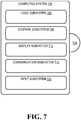
HMD 10.FIG. 7 schematically shows a nonlimiting embodiment of acomputing system 700 that may perform one or more of the above described methods and processes.Computing system 700 is shown in simplified form. It is to be understood that virtually any computer architecture may be used without departing from the scope of this disclosure. In different embodiments,computing system 700 may take the form ofcomputing device 38 integrated in theHMD 10, a mainframe computer, server computer, desktop computer, laptop computer, tablet computer, home entertainment computer, network computing device, mobile computing device, mobile communication device, gaming device, etc. - As shown in
FIG. 7 ,computing system 700 includes alogic subsystem 704 and astorage subsystem 708.Computing system 700 may optionally include adisplay subsystem 712, acommunication subsystem 716, aninput subsystem 720, and/or other subsystems and components not shown inFIG. 7 .Computing system 700 may also include computer readable media, with the computer readable media including computer readable storage media and computer readable communication media.Computing system 700 may also optionally include other user input devices such as keyboards, mice, game controllers, and/or touch screens, for example. Further, in some embodiments the methods and processes described herein may be implemented as a computer application, computer service, computer API, computer library, and/or other computer program product in a computing system that includes one or more computers. -
Logic subsystem 704 may include one or more physical devices configured to execute one or more instructions. For example, thelogic subsystem 704 may be configured to execute one or more instructions that are part of one or more applications, services, programs, routines, libraries, objects, components, data structures, or other logical constructs. Such instructions may be implemented to perform a task, implement a data type, transform the state of one or more devices, or otherwise arrive at a desired result. - The
logic subsystem 704 may include one or more processors that are configured to execute software instructions. Additionally or alternatively, the logic subsystem may include one or more hardware or firmware logic machines configured to execute hardware or firmware instructions. Processors of the logic subsystem may be single core or multicore, and the programs executed thereon may be configured for parallel or distributed processing. The logic subsystem may optionally include individual components that are distributed throughout two or more devices, which may be remotely located and/or configured for coordinated processing. One or more aspects of the logic subsystem may be virtualized and executed by remotely accessible networked computing devices configured in a cloud computing configuration. -
Storage subsystem 708 may include one or more physical, persistent devices configured to hold data and/or instructions executable by thelogic subsystem 704 to implement the herein described methods and processes. When such methods and processes are implemented, the state ofstorage subsystem 708 may be transformed (e.g., to hold different data). -
Storage subsystem 708 may include removable media and/or built-in devices.Storage subsystem 708 may include optical memory devices (e.g., CD, DVD, HD DVD, Blu-ray Disc, etc.), semiconductor memory devices (e.g., RAM, EPROM, EEPROM, etc.) and/or magnetic memory devices (e.g., hard disk drive, floppy disk drive, tape drive, MRAM, etc.), among others.Storage subsystem 708 may include devices with one or more of the following characteristics: volatile, nonvolatile, dynamic, static, read/write, read-only, random access, sequential access, location addressable, file addressable, and content addressable. - In some embodiments, aspects of
logic subsystem 704 andstorage subsystem 708 may be integrated into one or more common devices through which the functionally described herein may be enacted, at least in part. Such hardware-logic components may include field-programmable gate arrays (FPGAs), program- and application-specific integrated circuits (PASIC / ASICs), program- and application-specific standard products (PSSP / ASSPs), system-on-a-chip (SOC) systems, and complex programmable logic devices (CPLDs), for example. -
FIG. 7 also shows an aspect of thestorage subsystem 708 in the form of removable computerreadable storage media 724, which may be used to store data and/or instructions executable to implement the methods and processes described herein. Removable computer-readable storage media 724 may take the form of CDs, DVDs, HD DVDs, Blu-Ray Discs, EEPROMs, and/or floppy disks, among others. - It is to be appreciated that
storage subsystem 708 includes one or more physical, persistent devices, and excludes propagating signals per se. In contrast, in some embodiments aspects of the instructions described herein may be propagated by a pure signal (e.g., an electromagnetic signal, an optical signal, etc.) via a transmission medium. Furthermore, data and/or other forms of information pertaining to the present disclosure may be propagated by a pure signal via a transmission medium. - When included,
display subsystem 712 may be used to present a visual representation of data held bystorage subsystem 708. As the above described methods and processes change the data held by thestorage subsystem 708, and thus transform the state of the storage subsystem, the state of thedisplay subsystem 712 may likewise be transformed to visually represent changes in the underlying data. Thedisplay subsystem 712 may include one or more display devices utilizing virtually any type of technology. Such display devices may be combined withlogic subsystem 704 and/orstorage subsystem 708 in a shared enclosure, or such display devices may be peripheral display devices. - When included,
communication subsystem 716 may be configured to communicatively couplecomputing system 700 with one or more networks and/or one or more other computing devices.Communication subsystem 716 may include wired and/or wireless communication devices compatible with one or more different communication protocols. As nonlimiting examples, thecommunication subsystem 716 may be configured for communication via a wireless telephone network, a wireless local area network, a wired local area network, a wireless wide area network, a wired wide area network, etc. In some embodiments, the communication subsystem may allowcomputing system 700 to send and/or receive messages to and/or from other devices via a network such as the Internet. - When included,
input subsystem 720 may comprise or interface with one or more user-input devices such as a keyboard, mouse, microphone, touch screen, or game controller. In some embodiments, the input subsystem may comprise or interface with selected natural user input (NUI) componentry. Such componentry may be integrated or peripheral, and the transduction and/or processing of input actions may be handled on- or off-board. Example NUI componentry may include a microphone for speech and/or voice recognition; an infrared, color, stereoscopic, and/or depth camera for machine vision and/or gesture recognition; a head tracker, eye tracker, accelerometer, and/or gyroscope for motion detection and/or intent recognition; as well as electric-field sensing componentry for assessing brain activity. - The term "program" may be used to describe an aspect of the present disclosure that is implemented to perform one or more particular functions. In some cases, such a program may be instantiated via
logic subsystem 704 executing instructions held bystorage subsystem 708. It is to be understood that different programs may be instantiated from the same application, service, code block, object, library, routine, API, function, etc. Likewise, the same program may be instantiated by different applications, services, code blocks, objects, routines, APIs, functions, etc. The term "program" is meant to encompass individual or groups of executable files, data files, libraries, drivers, scripts, database records, etc. - It will be understood that the configurations and/or approaches described herein are presented for the purpose of example, and that these specific embodiments or examples are not to be considered in a limiting sense, because numerous variations are possible. The invention however is solely defined by the appended claims.
Claims (2)
- A head-mounted display (10) comprising:at least one image sensor (22); anda computing device (38) comprising:a logic subsystem (42); anda data-holding subsystem (34) comprising instructions stored thereon that are executable by the logic subsystem (42) to:identify, using image data from the at least one image sensor (22), a background object in a physical environment surrounding the head-mounted display (10) as a real world target (318; 514);via the head-mounted display (10), display a virtual marker (306; 506) being visually alignable with the real world target (318; 514) by a user (302) of the head-mounted display (10) by moving the head-mounted display (10);receive an input from the user (302) indicating that the user (302) has visually aligned the virtual marker (306; 506) with the real world target (318; 514);in response to receiving the input from the user (302), acquire image data from the head-mounted display (10) to determine a location of the real world target (318; 514);using the acquired image data, determine an estimated eye location relative to a location of the head-mounted display (10); andcalibrate a predetermined eye location based upon the estimated eye location, the predetermined eye location indicating a location of an eye of a user relative to the head-mounted display (10),characterized in that the virtual marker (306; 506) is aligned with a plurality of real world targets (318; 514) in a particular order to enter a user's password.
- A method (600) of calibrating a predetermined eye location for a head-mounted display, the predetermined eye location indicating a location of an eye of a user relative to the head-mounted display, the method (600) comprising:identifying, using image data from at least one image sensor, a background object in a physical environment surrounding the head-mounted display as a real world target;displaying (604) a virtual marker visually alignable with the real world target by a user of the head-mounted display by moving the head-mounted displayreceiving (620) an input from the user indicating that the user has visually aligned the virtual marker with the real world target;in response to receiving the input from the user, acquiring (616) image data to determine a location of the real world target;from the acquired image data, determining (624) an estimated eye location relative to a location of the head-mounted display; andcalibrating (648) the predetermined eye location based upon the estimated eye location,characterized in moving the head-mounted display to virtually align the virtual marker (306; 506) with a plurality of real world targets (318; 514) in a particular order to enter a user's password.
Applications Claiming Priority (2)
| Application Number | Priority Date | Filing Date | Title |
|---|---|---|---|
| US13/892,142 US9239460B2 (en) | 2013-05-10 | 2013-05-10 | Calibration of eye location |
| PCT/US2014/037411 WO2014182977A1 (en) | 2013-05-10 | 2014-05-09 | Calibration of eye location |
Publications (2)
| Publication Number | Publication Date |
|---|---|
| EP2994812A1 EP2994812A1 (en) | 2016-03-16 |
| EP2994812B1 true EP2994812B1 (en) | 2019-04-17 |
Family
ID=50942862
Family Applications (1)
| Application Number | Title | Priority Date | Filing Date |
|---|---|---|---|
| EP14730325.9A Active EP2994812B1 (en) | 2013-05-10 | 2014-05-09 | Calibration of eye location |
Country Status (4)
| Country | Link |
|---|---|
| US (1) | US9239460B2 (en) |
| EP (1) | EP2994812B1 (en) |
| CN (1) | CN105247448B (en) |
| WO (1) | WO2014182977A1 (en) |
Families Citing this family (58)
| Publication number | Priority date | Publication date | Assignee | Title |
|---|---|---|---|---|
| EP2904349B1 (en) * | 2012-10-01 | 2020-03-18 | Bodybarista ApS | A method of calibrating a camera |
| US10345903B2 (en) * | 2013-07-30 | 2019-07-09 | Microsoft Technology Licensing, Llc | Feedback for optic positioning in display devices |
| US10073518B2 (en) * | 2013-08-19 | 2018-09-11 | Qualcomm Incorporated | Automatic calibration of eye tracking for optical see-through head mounted display |
| US10372204B2 (en) | 2013-10-30 | 2019-08-06 | Technology Against Als | Communication and control system and method |
| US20150145887A1 (en) * | 2013-11-25 | 2015-05-28 | Qualcomm Incorporated | Persistent head-mounted content display |
| US9524580B2 (en) * | 2014-01-06 | 2016-12-20 | Oculus Vr, Llc | Calibration of virtual reality systems |
| US20150348322A1 (en) * | 2014-06-02 | 2015-12-03 | Dell Products L.P. | Dynamically Composited Information Handling System Augmented Reality at a Primary Display |
| US10198865B2 (en) * | 2014-07-10 | 2019-02-05 | Seiko Epson Corporation | HMD calibration with direct geometric modeling |
| US10070120B2 (en) * | 2014-09-17 | 2018-09-04 | Qualcomm Incorporated | Optical see-through display calibration |
| US10306217B2 (en) * | 2015-04-17 | 2019-05-28 | Seiko Epson Corporation | Display device, control method for display device, and computer program |
| JP6550885B2 (en) | 2015-04-21 | 2019-07-31 | セイコーエプソン株式会社 | Display device, display device control method, and program |
| US9746675B2 (en) * | 2015-05-28 | 2017-08-29 | Microsoft Technology Licensing, Llc | Alignment based view matrix tuning |
| US11252399B2 (en) * | 2015-05-28 | 2022-02-15 | Microsoft Technology Licensing, Llc | Determining inter-pupillary distance |
| EP4279972A3 (en) * | 2015-06-15 | 2024-03-06 | Essilor International | Method for calibrating a binocular displaying device |
| US10192133B2 (en) | 2015-06-22 | 2019-01-29 | Seiko Epson Corporation | Marker, method of detecting position and pose of marker, and computer program |
| US9898865B2 (en) * | 2015-06-22 | 2018-02-20 | Microsoft Technology Licensing, Llc | System and method for spawning drawing surfaces |
| US10192361B2 (en) | 2015-07-06 | 2019-01-29 | Seiko Epson Corporation | Head-mounted display device and computer program |
| US10149958B1 (en) * | 2015-07-17 | 2018-12-11 | Bao Tran | Systems and methods for computer assisted operation |
| JP6548821B2 (en) * | 2015-09-30 | 2019-07-24 | 株式会社ソニー・インタラクティブエンタテインメント | How to optimize the placement of content on the screen of a head mounted display |
| US10630965B2 (en) * | 2015-10-02 | 2020-04-21 | Microsoft Technology Licensing, Llc | Calibrating a near-eye display |
| US10424117B2 (en) | 2015-12-02 | 2019-09-24 | Seiko Epson Corporation | Controlling a display of a head-mounted display device |
| US10304446B2 (en) | 2016-02-03 | 2019-05-28 | Disney Enterprises, Inc. | Self calibration for smartphone goggles |
| US10334076B2 (en) * | 2016-02-22 | 2019-06-25 | Google Llc | Device pairing in augmented/virtual reality environment |
| IL245334B (en) * | 2016-04-21 | 2018-10-31 | Elbit Systems Ltd | Head wearable display reliability verification |
| US10423830B2 (en) * | 2016-04-22 | 2019-09-24 | Intel Corporation | Eye contact correction in real time using neural network based machine learning |
| US10496156B2 (en) * | 2016-05-17 | 2019-12-03 | Google Llc | Techniques to change location of objects in a virtual/augmented reality system |
| CN106123916B (en) * | 2016-06-13 | 2019-11-15 | 上海临奇智能科技有限公司 | It is a kind of for calibrating the method and apparatus of Inertial Measurement Unit in VR equipment |
| CN107015637B (en) * | 2016-10-27 | 2020-05-05 | 阿里巴巴集团控股有限公司 | Input method and device in virtual reality scene |
| US10928638B2 (en) * | 2016-10-31 | 2021-02-23 | Dolby Laboratories Licensing Corporation | Eyewear devices with focus tunable lenses |
| JP6852355B2 (en) * | 2016-11-09 | 2021-03-31 | セイコーエプソン株式会社 | Program, head-mounted display device |
| KR101894846B1 (en) * | 2017-05-19 | 2018-09-04 | 주식회사 맥스트 | Calibration method for matching of augmented reality object and head mounted display for executing the method |
| CA3065131A1 (en) * | 2017-05-31 | 2018-12-06 | Magic Leap, Inc. | Eye tracking calibration techniques |
| KR102401168B1 (en) | 2017-10-27 | 2022-05-24 | 삼성전자주식회사 | Method and apparatus for calibrating parameter of 3d display apparatus |
| CN109725418B (en) * | 2017-10-30 | 2020-10-16 | 华为技术有限公司 | Display device, method and device for adjusting image presentation of display device |
| AU2018367510A1 (en) * | 2017-11-14 | 2020-06-25 | Vivid Vision, Inc. | Systems and methods for visual field analysis |
| EP3729378B1 (en) | 2017-12-19 | 2021-07-21 | Telefonaktiebolaget Lm Ericsson (Publ) | Head-mounted display device and method thereof |
| US10523912B2 (en) * | 2018-02-01 | 2019-12-31 | Microsoft Technology Licensing, Llc | Displaying modified stereo visual content |
| WO2019160698A2 (en) * | 2018-02-16 | 2019-08-22 | Valve Corporation | Using detected pupil location to align optical components of a head-mounted display |
| US10902680B2 (en) * | 2018-04-03 | 2021-01-26 | Saeed Eslami | Augmented reality application system and method |
| US10928900B2 (en) | 2018-04-27 | 2021-02-23 | Technology Against Als | Communication systems and methods |
| CN108592865A (en) * | 2018-04-28 | 2018-09-28 | 京东方科技集团股份有限公司 | Geometric measurement method and its device, AR equipment based on AR equipment |
| WO2019220464A1 (en) * | 2018-05-16 | 2019-11-21 | Cartosense Pvt. Ltd. | A system and method for alignment between real and virtual objects in a head-mounted optical see-through display |
| CN110554511B (en) * | 2018-05-30 | 2022-05-03 | 托比股份公司 | Method and apparatus for calibrating head mounted display |
| US11215828B1 (en) * | 2018-08-03 | 2022-01-04 | Rockwell Collins, Inc. | In field visor characterization for visor projected displays |
| CN110874868A (en) * | 2018-09-03 | 2020-03-10 | 广东虚拟现实科技有限公司 | Data processing method and device, terminal equipment and storage medium |
| US10776954B2 (en) * | 2018-10-08 | 2020-09-15 | Microsoft Technology Licensing, Llc | Real-world anchor in a virtual-reality environment |
| JP7148634B2 (en) * | 2018-12-04 | 2022-10-05 | マクセル株式会社 | head mounted display device |
| AT522012A1 (en) * | 2018-12-19 | 2020-07-15 | Viewpointsystem Gmbh | Method for adapting an optical system to an individual user |
| CN113196139B (en) | 2018-12-20 | 2023-08-11 | 美国斯耐普公司 | Flexible eye-wear device with dual cameras for generating stereoscopic images |
| US10895949B2 (en) * | 2019-02-22 | 2021-01-19 | Htc Corporation | Head mounted display and display method for eye-tracking cursor |
| WO2020185219A1 (en) * | 2019-03-13 | 2020-09-17 | Hewlett-Packard Development Company, L.P. | Detecting eye tracking calibration errors |
| US11333888B2 (en) | 2019-08-05 | 2022-05-17 | Facebook Technologies, Llc | Automatic position determination of head mounted display optics |
| US10991343B2 (en) * | 2019-08-05 | 2021-04-27 | Facebook Technologies, Llc | Automatic image alignment with head mounted display optics |
| US11054659B2 (en) * | 2019-11-07 | 2021-07-06 | Htc Corporation | Head mounted display apparatus and distance measurement device thereof |
| US10965931B1 (en) * | 2019-12-06 | 2021-03-30 | Snap Inc. | Sensor misalignment compensation |
| CN111643887B (en) * | 2020-06-08 | 2023-07-14 | 歌尔科技有限公司 | Headset, data processing method thereof and computer readable storage medium |
| CN115278203A (en) * | 2022-07-20 | 2022-11-01 | 广州视享科技有限公司 | Calibration method and calibration device for virtual reality equipment and calibration robot |
| CN115953813B (en) * | 2022-12-19 | 2024-01-30 | 北京字跳网络技术有限公司 | Expression driving method, device, equipment and storage medium |
Family Cites Families (21)
| Publication number | Priority date | Publication date | Assignee | Title |
|---|---|---|---|---|
| EP0933720A3 (en) | 1998-01-29 | 1999-11-10 | Shimadzu Corporation | Input apparatus for the physically handicapped |
| US6753828B2 (en) * | 2000-09-25 | 2004-06-22 | Siemens Corporated Research, Inc. | System and method for calibrating a stereo optical see-through head-mounted display system for augmented reality |
| US7190331B2 (en) | 2002-06-06 | 2007-03-13 | Siemens Corporate Research, Inc. | System and method for measuring the registration accuracy of an augmented reality system |
| US6943754B2 (en) | 2002-09-27 | 2005-09-13 | The Boeing Company | Gaze tracking system, eye-tracking assembly and an associated method of calibration |
| CN100416336C (en) * | 2003-06-12 | 2008-09-03 | 美国西门子医疗解决公司 | Calibrating real and virtual views |
| US7369101B2 (en) * | 2003-06-12 | 2008-05-06 | Siemens Medical Solutions Usa, Inc. | Calibrating real and virtual views |
| WO2006012678A1 (en) | 2004-08-03 | 2006-02-09 | Silverbrook Research Pty Ltd | Walk-up printing |
| US9323055B2 (en) | 2006-05-26 | 2016-04-26 | Exelis, Inc. | System and method to display maintenance and operational instructions of an apparatus using augmented reality |
| US7986816B1 (en) | 2006-09-27 | 2011-07-26 | University Of Alaska | Methods and systems for multiple factor authentication using gaze tracking and iris scanning |
| WO2008055262A2 (en) | 2006-11-02 | 2008-05-08 | Sensics, Inc. | Systems and methods for a head-mounted display |
| US8120857B2 (en) | 2008-10-15 | 2012-02-21 | Gentex Corporation | Apparatus and method for mounting and calibrating a helmet-mounted display |
| US9323056B2 (en) | 2009-12-17 | 2016-04-26 | Bae Systems Plc | Method of aligning a helmet mounted display |
| US8482859B2 (en) | 2010-02-28 | 2013-07-09 | Osterhout Group, Inc. | See-through near-eye display glasses wherein image light is transmitted to and reflected from an optically flat film |
| US8884984B2 (en) | 2010-10-15 | 2014-11-11 | Microsoft Corporation | Fusing virtual content into real content |
| US8872766B2 (en) | 2011-05-10 | 2014-10-28 | Raytheon Company | System and method for operating a helmet mounted display |
| US8510166B2 (en) | 2011-05-11 | 2013-08-13 | Google Inc. | Gaze tracking system |
| US9727132B2 (en) | 2011-07-01 | 2017-08-08 | Microsoft Technology Licensing, Llc | Multi-visor: managing applications in augmented reality environments |
| US9213163B2 (en) | 2011-08-30 | 2015-12-15 | Microsoft Technology Licensing, Llc | Aligning inter-pupillary distance in a near-eye display system |
| US9025252B2 (en) | 2011-08-30 | 2015-05-05 | Microsoft Technology Licensing, Llc | Adjustment of a mixed reality display for inter-pupillary distance alignment |
| US9164580B2 (en) | 2012-08-24 | 2015-10-20 | Microsoft Technology Licensing, Llc | Calibration of eye tracking system |
| TWI486629B (en) * | 2012-11-21 | 2015-06-01 | Ind Tech Res Inst | Optical-see-through head mounted display system and interactive operation |
-
2013
- 2013-05-10 US US13/892,142 patent/US9239460B2/en active Active
-
2014
- 2014-05-09 EP EP14730325.9A patent/EP2994812B1/en active Active
- 2014-05-09 CN CN201480026457.8A patent/CN105247448B/en active Active
- 2014-05-09 WO PCT/US2014/037411 patent/WO2014182977A1/en active Application Filing
Non-Patent Citations (1)
| Title |
|---|
| None * |
Also Published As
| Publication number | Publication date |
|---|---|
| CN105247448A (en) | 2016-01-13 |
| CN105247448B (en) | 2018-04-10 |
| US9239460B2 (en) | 2016-01-19 |
| EP2994812A1 (en) | 2016-03-16 |
| US20140333665A1 (en) | 2014-11-13 |
| WO2014182977A1 (en) | 2014-11-13 |
Similar Documents
| Publication | Publication Date | Title |
|---|---|---|
| EP2994812B1 (en) | Calibration of eye location | |
| US10248199B2 (en) | Gaze detection calibration | |
| US10740960B2 (en) | Virtual object placement for augmented reality | |
| KR102460047B1 (en) | Head up display with eye tracking device determining user spectacles characteristics | |
| US9824499B2 (en) | Mixed-reality image capture | |
| US10630965B2 (en) | Calibrating a near-eye display | |
| US9977492B2 (en) | Mixed reality presentation | |
| US9473764B2 (en) | Stereoscopic image display | |
| US11683470B2 (en) | Determining inter-pupillary distance | |
| US20160212538A1 (en) | Spatial audio with remote speakers | |
| KR20170090490A (en) | Gaze target application launcher | |
| KR20160106629A (en) | Target positioning with gaze tracking | |
| EP3014343A1 (en) | Adjusting a near-eye display device | |
| KR20160022922A (en) | User interface navigation | |
| WO2016118344A1 (en) | Fixed size augmented reality objects | |
| US20200242335A1 (en) | Information processing apparatus, information processing method, and recording medium | |
| US20220172405A1 (en) | Velocity-based controls |
Legal Events
| Date | Code | Title | Description |
|---|---|---|---|
| PUAI | Public reference made under article 153(3) epc to a published international application that has entered the european phase |
Free format text: ORIGINAL CODE: 0009012 |
|
| 17P | Request for examination filed |
Effective date: 20151109 |
|
| AK | Designated contracting states |
Kind code of ref document: A1 Designated state(s): AL AT BE BG CH CY CZ DE DK EE ES FI FR GB GR HR HU IE IS IT LI LT LU LV MC MK MT NL NO PL PT RO RS SE SI SK SM TR |
|
| AX | Request for extension of the european patent |
Extension state: BA ME |
|
| DAX | Request for extension of the european patent (deleted) | ||
| RIC1 | Information provided on ipc code assigned before grant |
Ipc: G06F 3/01 20060101AFI20161005BHEP Ipc: G02B 7/12 20060101ALI20161005BHEP Ipc: G02B 27/01 20060101ALI20161005BHEP |
|
| GRAP | Despatch of communication of intention to grant a patent |
Free format text: ORIGINAL CODE: EPIDOSNIGR1 |
|
| STAA | Information on the status of an ep patent application or granted ep patent |
Free format text: STATUS: GRANT OF PATENT IS INTENDED |
|
| INTG | Intention to grant announced |
Effective date: 20161124 |
|
| GRAJ | Information related to disapproval of communication of intention to grant by the applicant or resumption of examination proceedings by the epo deleted |
Free format text: ORIGINAL CODE: EPIDOSDIGR1 |
|
| STAA | Information on the status of an ep patent application or granted ep patent |
Free format text: STATUS: REQUEST FOR EXAMINATION WAS MADE |
|
| INTC | Intention to grant announced (deleted) | ||
| STAA | Information on the status of an ep patent application or granted ep patent |
Free format text: STATUS: EXAMINATION IS IN PROGRESS |
|
| 17Q | First examination report despatched |
Effective date: 20170504 |
|
| GRAP | Despatch of communication of intention to grant a patent |
Free format text: ORIGINAL CODE: EPIDOSNIGR1 |
|
| STAA | Information on the status of an ep patent application or granted ep patent |
Free format text: STATUS: GRANT OF PATENT IS INTENDED |
|
| INTG | Intention to grant announced |
Effective date: 20181115 |
|
| GRAS | Grant fee paid |
Free format text: ORIGINAL CODE: EPIDOSNIGR3 |
|
| GRAA | (expected) grant |
Free format text: ORIGINAL CODE: 0009210 |
|
| STAA | Information on the status of an ep patent application or granted ep patent |
Free format text: STATUS: THE PATENT HAS BEEN GRANTED |
|
| AK | Designated contracting states |
Kind code of ref document: B1 Designated state(s): AL AT BE BG CH CY CZ DE DK EE ES FI FR GB GR HR HU IE IS IT LI LT LU LV MC MK MT NL NO PL PT RO RS SE SI SK SM TR |
|
| REG | Reference to a national code |
Ref country code: GB Ref legal event code: FG4D |
|
| REG | Reference to a national code |
Ref country code: CH Ref legal event code: EP |
|
| REG | Reference to a national code |
Ref country code: DE Ref legal event code: R096 Ref document number: 602014044875 Country of ref document: DE |
|
| REG | Reference to a national code |
Ref country code: AT Ref legal event code: REF Ref document number: 1122277 Country of ref document: AT Kind code of ref document: T Effective date: 20190515 Ref country code: IE Ref legal event code: FG4D |
|
| REG | Reference to a national code |
Ref country code: NL Ref legal event code: FP |
|
| REG | Reference to a national code |
Ref country code: LT Ref legal event code: MG4D |
|
| PG25 | Lapsed in a contracting state [announced via postgrant information from national office to epo] |
Ref country code: HR Free format text: LAPSE BECAUSE OF FAILURE TO SUBMIT A TRANSLATION OF THE DESCRIPTION OR TO PAY THE FEE WITHIN THE PRESCRIBED TIME-LIMIT Effective date: 20190417 Ref country code: NO Free format text: LAPSE BECAUSE OF FAILURE TO SUBMIT A TRANSLATION OF THE DESCRIPTION OR TO PAY THE FEE WITHIN THE PRESCRIBED TIME-LIMIT Effective date: 20190717 Ref country code: SE Free format text: LAPSE BECAUSE OF FAILURE TO SUBMIT A TRANSLATION OF THE DESCRIPTION OR TO PAY THE FEE WITHIN THE PRESCRIBED TIME-LIMIT Effective date: 20190417 Ref country code: FI Free format text: LAPSE BECAUSE OF FAILURE TO SUBMIT A TRANSLATION OF THE DESCRIPTION OR TO PAY THE FEE WITHIN THE PRESCRIBED TIME-LIMIT Effective date: 20190417 Ref country code: AL Free format text: LAPSE BECAUSE OF FAILURE TO SUBMIT A TRANSLATION OF THE DESCRIPTION OR TO PAY THE FEE WITHIN THE PRESCRIBED TIME-LIMIT Effective date: 20190417 Ref country code: PT Free format text: LAPSE BECAUSE OF FAILURE TO SUBMIT A TRANSLATION OF THE DESCRIPTION OR TO PAY THE FEE WITHIN THE PRESCRIBED TIME-LIMIT Effective date: 20190817 Ref country code: ES Free format text: LAPSE BECAUSE OF FAILURE TO SUBMIT A TRANSLATION OF THE DESCRIPTION OR TO PAY THE FEE WITHIN THE PRESCRIBED TIME-LIMIT Effective date: 20190417 Ref country code: LT Free format text: LAPSE BECAUSE OF FAILURE TO SUBMIT A TRANSLATION OF THE DESCRIPTION OR TO PAY THE FEE WITHIN THE PRESCRIBED TIME-LIMIT Effective date: 20190417 |
|
| PG25 | Lapsed in a contracting state [announced via postgrant information from national office to epo] |
Ref country code: BG Free format text: LAPSE BECAUSE OF FAILURE TO SUBMIT A TRANSLATION OF THE DESCRIPTION OR TO PAY THE FEE WITHIN THE PRESCRIBED TIME-LIMIT Effective date: 20190717 Ref country code: PL Free format text: LAPSE BECAUSE OF FAILURE TO SUBMIT A TRANSLATION OF THE DESCRIPTION OR TO PAY THE FEE WITHIN THE PRESCRIBED TIME-LIMIT Effective date: 20190417 Ref country code: RS Free format text: LAPSE BECAUSE OF FAILURE TO SUBMIT A TRANSLATION OF THE DESCRIPTION OR TO PAY THE FEE WITHIN THE PRESCRIBED TIME-LIMIT Effective date: 20190417 Ref country code: GR Free format text: LAPSE BECAUSE OF FAILURE TO SUBMIT A TRANSLATION OF THE DESCRIPTION OR TO PAY THE FEE WITHIN THE PRESCRIBED TIME-LIMIT Effective date: 20190718 Ref country code: LV Free format text: LAPSE BECAUSE OF FAILURE TO SUBMIT A TRANSLATION OF THE DESCRIPTION OR TO PAY THE FEE WITHIN THE PRESCRIBED TIME-LIMIT Effective date: 20190417 |
|
| REG | Reference to a national code |
Ref country code: DE Ref legal event code: R082 Ref document number: 602014044875 Country of ref document: DE |
|
| REG | Reference to a national code |
Ref country code: AT Ref legal event code: MK05 Ref document number: 1122277 Country of ref document: AT Kind code of ref document: T Effective date: 20190417 |
|
| REG | Reference to a national code |
Ref country code: CH Ref legal event code: PL |
|
| PG25 | Lapsed in a contracting state [announced via postgrant information from national office to epo] |
Ref country code: IS Free format text: LAPSE BECAUSE OF FAILURE TO SUBMIT A TRANSLATION OF THE DESCRIPTION OR TO PAY THE FEE WITHIN THE PRESCRIBED TIME-LIMIT Effective date: 20190817 |
|
| REG | Reference to a national code |
Ref country code: DE Ref legal event code: R097 Ref document number: 602014044875 Country of ref document: DE |
|
| PG25 | Lapsed in a contracting state [announced via postgrant information from national office to epo] |
Ref country code: SK Free format text: LAPSE BECAUSE OF FAILURE TO SUBMIT A TRANSLATION OF THE DESCRIPTION OR TO PAY THE FEE WITHIN THE PRESCRIBED TIME-LIMIT Effective date: 20190417 Ref country code: RO Free format text: LAPSE BECAUSE OF FAILURE TO SUBMIT A TRANSLATION OF THE DESCRIPTION OR TO PAY THE FEE WITHIN THE PRESCRIBED TIME-LIMIT Effective date: 20190417 Ref country code: CZ Free format text: LAPSE BECAUSE OF FAILURE TO SUBMIT A TRANSLATION OF THE DESCRIPTION OR TO PAY THE FEE WITHIN THE PRESCRIBED TIME-LIMIT Effective date: 20190417 Ref country code: LI Free format text: LAPSE BECAUSE OF NON-PAYMENT OF DUE FEES Effective date: 20190531 Ref country code: DK Free format text: LAPSE BECAUSE OF FAILURE TO SUBMIT A TRANSLATION OF THE DESCRIPTION OR TO PAY THE FEE WITHIN THE PRESCRIBED TIME-LIMIT Effective date: 20190417 Ref country code: AT Free format text: LAPSE BECAUSE OF FAILURE TO SUBMIT A TRANSLATION OF THE DESCRIPTION OR TO PAY THE FEE WITHIN THE PRESCRIBED TIME-LIMIT Effective date: 20190417 Ref country code: EE Free format text: LAPSE BECAUSE OF FAILURE TO SUBMIT A TRANSLATION OF THE DESCRIPTION OR TO PAY THE FEE WITHIN THE PRESCRIBED TIME-LIMIT Effective date: 20190417 Ref country code: MC Free format text: LAPSE BECAUSE OF FAILURE TO SUBMIT A TRANSLATION OF THE DESCRIPTION OR TO PAY THE FEE WITHIN THE PRESCRIBED TIME-LIMIT Effective date: 20190417 Ref country code: CH Free format text: LAPSE BECAUSE OF NON-PAYMENT OF DUE FEES Effective date: 20190531 |
|
| REG | Reference to a national code |
Ref country code: BE Ref legal event code: MM Effective date: 20190531 |
|
| PLBE | No opposition filed within time limit |
Free format text: ORIGINAL CODE: 0009261 |
|
| STAA | Information on the status of an ep patent application or granted ep patent |
Free format text: STATUS: NO OPPOSITION FILED WITHIN TIME LIMIT |
|
| PG25 | Lapsed in a contracting state [announced via postgrant information from national office to epo] |
Ref country code: LU Free format text: LAPSE BECAUSE OF NON-PAYMENT OF DUE FEES Effective date: 20190509 Ref country code: SM Free format text: LAPSE BECAUSE OF FAILURE TO SUBMIT A TRANSLATION OF THE DESCRIPTION OR TO PAY THE FEE WITHIN THE PRESCRIBED TIME-LIMIT Effective date: 20190417 Ref country code: IT Free format text: LAPSE BECAUSE OF FAILURE TO SUBMIT A TRANSLATION OF THE DESCRIPTION OR TO PAY THE FEE WITHIN THE PRESCRIBED TIME-LIMIT Effective date: 20190417 |
|
| 26N | No opposition filed |
Effective date: 20200120 |
|
| PG25 | Lapsed in a contracting state [announced via postgrant information from national office to epo] |
Ref country code: TR Free format text: LAPSE BECAUSE OF FAILURE TO SUBMIT A TRANSLATION OF THE DESCRIPTION OR TO PAY THE FEE WITHIN THE PRESCRIBED TIME-LIMIT Effective date: 20190417 |
|
| PG25 | Lapsed in a contracting state [announced via postgrant information from national office to epo] |
Ref country code: IE Free format text: LAPSE BECAUSE OF NON-PAYMENT OF DUE FEES Effective date: 20190509 |
|
| PG25 | Lapsed in a contracting state [announced via postgrant information from national office to epo] |
Ref country code: BE Free format text: LAPSE BECAUSE OF NON-PAYMENT OF DUE FEES Effective date: 20190531 Ref country code: SI Free format text: LAPSE BECAUSE OF FAILURE TO SUBMIT A TRANSLATION OF THE DESCRIPTION OR TO PAY THE FEE WITHIN THE PRESCRIBED TIME-LIMIT Effective date: 20190417 |
|
| PG25 | Lapsed in a contracting state [announced via postgrant information from national office to epo] |
Ref country code: CY Free format text: LAPSE BECAUSE OF FAILURE TO SUBMIT A TRANSLATION OF THE DESCRIPTION OR TO PAY THE FEE WITHIN THE PRESCRIBED TIME-LIMIT Effective date: 20190417 |
|
| PG25 | Lapsed in a contracting state [announced via postgrant information from national office to epo] |
Ref country code: HU Free format text: LAPSE BECAUSE OF FAILURE TO SUBMIT A TRANSLATION OF THE DESCRIPTION OR TO PAY THE FEE WITHIN THE PRESCRIBED TIME-LIMIT; INVALID AB INITIO Effective date: 20140509 Ref country code: MT Free format text: LAPSE BECAUSE OF FAILURE TO SUBMIT A TRANSLATION OF THE DESCRIPTION OR TO PAY THE FEE WITHIN THE PRESCRIBED TIME-LIMIT Effective date: 20190417 |
|
| PG25 | Lapsed in a contracting state [announced via postgrant information from national office to epo] |
Ref country code: MK Free format text: LAPSE BECAUSE OF FAILURE TO SUBMIT A TRANSLATION OF THE DESCRIPTION OR TO PAY THE FEE WITHIN THE PRESCRIBED TIME-LIMIT Effective date: 20190417 |
|
| P01 | Opt-out of the competence of the unified patent court (upc) registered |
Effective date: 20230501 |
|
| PGFP | Annual fee paid to national office [announced via postgrant information from national office to epo] |
Ref country code: NL Payment date: 20230419 Year of fee payment: 10 |
|
| PGFP | Annual fee paid to national office [announced via postgrant information from national office to epo] |
Ref country code: FR Payment date: 20230420 Year of fee payment: 10 Ref country code: DE Payment date: 20230419 Year of fee payment: 10 |
|
| PGFP | Annual fee paid to national office [announced via postgrant information from national office to epo] |
Ref country code: GB Payment date: 20230420 Year of fee payment: 10 |