EP2990893B1 - Power supply returning apparatus - Google Patents
Power supply returning apparatus Download PDFInfo
- Publication number
- EP2990893B1 EP2990893B1 EP14788560.2A EP14788560A EP2990893B1 EP 2990893 B1 EP2990893 B1 EP 2990893B1 EP 14788560 A EP14788560 A EP 14788560A EP 2990893 B1 EP2990893 B1 EP 2990893B1
- Authority
- EP
- European Patent Office
- Prior art keywords
- power input
- input port
- power
- powering
- electronic equipment
- Prior art date
- Legal status (The legal status is an assumption and is not a legal conclusion. Google has not performed a legal analysis and makes no representation as to the accuracy of the status listed.)
- Active
Links
- 230000002441 reversible effect Effects 0.000 claims description 35
- 238000006243 chemical reaction Methods 0.000 claims description 11
- 230000002093 peripheral effect Effects 0.000 description 10
- 238000010586 diagram Methods 0.000 description 8
- 238000000034 method Methods 0.000 description 3
- 230000005540 biological transmission Effects 0.000 description 2
- 230000001419 dependent effect Effects 0.000 description 1
- 230000009977 dual effect Effects 0.000 description 1
- 238000009434 installation Methods 0.000 description 1
- 238000012544 monitoring process Methods 0.000 description 1
- 230000006855 networking Effects 0.000 description 1
Images

Classifications
-
- H—ELECTRICITY
- H02—GENERATION; CONVERSION OR DISTRIBUTION OF ELECTRIC POWER
- H02J—CIRCUIT ARRANGEMENTS OR SYSTEMS FOR SUPPLYING OR DISTRIBUTING ELECTRIC POWER; SYSTEMS FOR STORING ELECTRIC ENERGY
- H02J1/00—Circuit arrangements for dc mains or dc distribution networks
- H02J1/10—Parallel operation of dc sources
- H02J1/108—Parallel operation of dc sources using diodes blocking reverse current flow
-
- H—ELECTRICITY
- H02—GENERATION; CONVERSION OR DISTRIBUTION OF ELECTRIC POWER
- H02J—CIRCUIT ARRANGEMENTS OR SYSTEMS FOR SUPPLYING OR DISTRIBUTING ELECTRIC POWER; SYSTEMS FOR STORING ELECTRIC ENERGY
- H02J9/00—Circuit arrangements for emergency or stand-by power supply, e.g. for emergency lighting
- H02J9/04—Circuit arrangements for emergency or stand-by power supply, e.g. for emergency lighting in which the distribution system is disconnected from the normal source and connected to a standby source
- H02J9/06—Circuit arrangements for emergency or stand-by power supply, e.g. for emergency lighting in which the distribution system is disconnected from the normal source and connected to a standby source with automatic change-over, e.g. UPS systems
- H02J9/061—Circuit arrangements for emergency or stand-by power supply, e.g. for emergency lighting in which the distribution system is disconnected from the normal source and connected to a standby source with automatic change-over, e.g. UPS systems for DC powered loads
-
- Y—GENERAL TAGGING OF NEW TECHNOLOGICAL DEVELOPMENTS; GENERAL TAGGING OF CROSS-SECTIONAL TECHNOLOGIES SPANNING OVER SEVERAL SECTIONS OF THE IPC; TECHNICAL SUBJECTS COVERED BY FORMER USPC CROSS-REFERENCE ART COLLECTIONS [XRACs] AND DIGESTS
- Y02—TECHNOLOGIES OR APPLICATIONS FOR MITIGATION OR ADAPTATION AGAINST CLIMATE CHANGE
- Y02B—CLIMATE CHANGE MITIGATION TECHNOLOGIES RELATED TO BUILDINGS, e.g. HOUSING, HOUSE APPLIANCES OR RELATED END-USER APPLICATIONS
- Y02B90/00—Enabling technologies or technologies with a potential or indirect contribution to GHG emissions mitigation
- Y02B90/20—Smart grids as enabling technology in buildings sector
-
- Y—GENERAL TAGGING OF NEW TECHNOLOGICAL DEVELOPMENTS; GENERAL TAGGING OF CROSS-SECTIONAL TECHNOLOGIES SPANNING OVER SEVERAL SECTIONS OF THE IPC; TECHNICAL SUBJECTS COVERED BY FORMER USPC CROSS-REFERENCE ART COLLECTIONS [XRACs] AND DIGESTS
- Y04—INFORMATION OR COMMUNICATION TECHNOLOGIES HAVING AN IMPACT ON OTHER TECHNOLOGY AREAS
- Y04S—SYSTEMS INTEGRATING TECHNOLOGIES RELATED TO POWER NETWORK OPERATION, COMMUNICATION OR INFORMATION TECHNOLOGIES FOR IMPROVING THE ELECTRICAL POWER GENERATION, TRANSMISSION, DISTRIBUTION, MANAGEMENT OR USAGE, i.e. SMART GRIDS
- Y04S20/00—Management or operation of end-user stationary applications or the last stages of power distribution; Controlling, monitoring or operating thereof
- Y04S20/12—Energy storage units, uninterruptible power supply [UPS] systems or standby or emergency generators, e.g. in the last power distribution stages
Definitions
- the present invention relates to the field of electronic equipment power supply technology, particularly to a reversible powering device.
- a surveillance camera could be powered by an external power supply unit or by POE (Power over Ethernet, which means remote powering over Ethernet, namely transmitting network signals and power to electronic equipments through one networking cable) or POC (Power over Cable, which means transmitting video signals and power to electronic equipments through one coaxial cable).
- POE Power over Ethernet
- POC Power over Cable
- peripheral equipments of a surveillance camera are often powered by external power units.
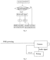
- Fig. 1 shows a powering mode for prior art surveillance cameras and pickups. The camera is powered by POE, while a 220V AC power is converted into a 12V DC power by an adapter to power the pickup.
- US 2012/229074 A1 discloses dual rate charger for notebook computer.
- US 2011/121653 A1 discloses parallel powering of portable electrical devices.
- US 2011/0080048 A1 discloses electronic assembly provided with a parallel circuit for connecting electrically to two battery units.
- US 2011/125341 A1 discloses providing power to powered device having multiple power supply inputs.
- CN 102 497276 A discloses a power source conversion circuit and a network camera with the circuit.
- One object of the present invention is to provide a reversible powering device that enables the electronic equipment using the reversible powering device to power another electronic equipment directly.
- Another object of the present invention is to reduce the cost for powering equipments.
- Yet another object of the present invention is to design a simple and effective reversible powering circuitry for powering other electronic equipments.
- a reversible powering device In order to address the above problem, the present disclosure proposes a reversible powering device.
- the reversible powering device is not only applicable to surveillance cameras and peripheral equipments, but also applicable to other electronic equipments with the same problem. Detail description will be given below with respect to specific exemplary embodiments.
- the electronic equipment used in the inventive technology must have at least two power input ports.
- the reversible powering device logically includes a power input determining module and a switch controlling module.
- the power input determining module is configured to determine whether the first power input port and the second power input port of the electronic equipment have a power input. If it is determined that the first power input port has power input while the second power input port has no power input, a control signal is sent to the switch controlling module.
- the switch controlling module is configured to control a switch device according to said control signal such that the power input into the first power input port can be output from the second power input port in a reverse direction to power another electronic equipment.
- the electronic equipment has at least two power input ports.
- the electronic equipment has a power input port A for powering the electronic equipment in a manner of POE or POC.
- the electronic equipment further has a power input port B for powering the electronic equipment with DC power. While powering the electronic equipment in practice, it is possible to power the electronic equipment only through the power input port A, or only through the power input port B, or through both power input port A and power input port B.
- the two powering modes herein are only examples, and other powering modes are not excluded.
- one original power input port is skillfully used as a power output port for powering peripheral equipments.
- the reversible powering device of the present exemplary embodiment includes an enable determining module for determining whether the electronic equipment enables the reversible powering function after the electronic equipment is powered on. If the reversible powering function is enabled, the power input determining module implements said determination.
- Fig. 3 shows a design chart of a reversible powering output device according to an example of the present disclosure.
- the design chart includes two sections in which one is a schematic diagram of a power circuit for the electronic equipment and the other is a schematic diagram of the reversible powering output circuitry.
- Fig. 3 is explained with POE or POC powering and 12V DC power as an example.
- the electronic equipment power circuit is shown by a dashed box in the figure.
- the conversion unit 31 converts power input from POE or POC port into DC power that is output and concentrated to the power bus via a diode 32.
- Another DC power (DC 12V input) is input from the DC power input port and then output and concentrated to the power bus via another diode 33. It is possible that these two ways of DC power may power the electronic equipment at the same time or only one way powers the electronic equipment.
- the diodes mainly functions to avoid mutual interference between the POE/POC powering voltage and the 12V voltage in case of being input together. Another function of the diodes is to isolate one and the next stage voltages to and avoid interference with the preceding stage by the next stage.
- the schematic diagram of the reversible powering circuitry includes a processor 37 with an output pin connected with a switching device 34 that is connected in parallel to a diode 33.
- the switching device 34 may be a relay switch, a low on-impedance MOS or other switchable devices. The switch is in off-state by default.
- the output of the conversion unit 31 is input into the processor 37 via a level conversion circuit 36 and the DC current input from the DC power input port is input into the processor 37 via another level conversion circuit 35.
- the input to the processor 37 via the level conversion circuits 35 and 36 serves as a powering status signal for the electronic equipment to be detected by the processor 37.
- the level conversion circuit 35 is disposed here. Based on the same reason, the level conversion circuit 36 is provided. Since the diodes 32 and 33 can function to isolate preceding and next stage voltages and avoid interference with preceding stage by the next stage, diodes provide guarantee for the processor 37 to determine the powering status signal and avoid misjudgement.
- the processor 37 may be a dedicated chip, a single chip machine, a CPLD, a FPGA or a DSP.
- the reversible powering function is enable controlled by the enable signal that is input into the processor 37 to implement enable and disable operations.
- the work flow of the system according to the present embodiment is as shown in Fig. 4 . It is assumed that in case of no power input, the powering status signal into the processor is 0, and in case of power input, the powering status signal into the processor is 1; input to the DC power input port is at high level, and power input to the POE/POC is at low level.
- step S1 after the system is powered on, it is determined whether the reversible powering function is enabled, and if so, the process proceeds to step S2, if not, proceeds to step S4.
- the customer can enable or disable the reversible powering function by pressing a button on the electronic equipment or clicking on the operation interface of the software client. If the customer enables the reversible powering function, it means the customer connects a peripheral equipment at the DC 12V input port.
- step S2 the powering status signal is read, when the status signal is 01, the process proceeds to step S3; and when the status signal is 10 or 11, the process proceeds to step S4.
- step S3 reversible powering function is implemented.
- step S4 reversible powering function is disabled.
- a status signal of 01 represents input at the POE or POC port and no input at the DC power input port. Now, power can be back fed through the DC power input port.
- a status signal of 10 represents no input at POE or POC port and input at DC power input port. Now the reversible powering function is disabled.
- a status signal of 11 represents inputs at both two ports. In this case, even if the customer enables the reversible powering function, the system will not provide reversed powering at the DC power input port.
- the processor can output signals to close the switch of the switching device such that the DC power from POE or POC port will be output via the switch input port to power the peripheral electronic equipment.
- the reversible powering enable signal is determined only once after the system is powered on and will not be determined afterwards unless the system is powered on again. Doing so mainly because while implementing reversible powering function, the system status signal will be read as 11, and the reversible powering function should be disabled according to the above-mentioned system flowchart. This would cause the system to enable and disable the reversible powering function continuously, causing the peripheral equipment can not work properly.
- Fig. 5 is a schematic diagram of powering a camera and its peripheral electronic equipment, a pickup using the technology according to an example of the present disclosure.
- the camera is powered by POE, and the pickup is powered by the DC power output by the power input port of the camera.
- no separate transmission lines and power adapter is needed, which saves costs on the one hand and is simple and convenient on the other hand.
Landscapes
- Engineering & Computer Science (AREA)
- Power Engineering (AREA)
- Business, Economics & Management (AREA)
- Emergency Management (AREA)
- Direct Current Feeding And Distribution (AREA)
- Dc-Dc Converters (AREA)
- Power Sources (AREA)
Description
- The present invention relates to the field of electronic equipment power supply technology, particularly to a reversible powering device.
- Surveillance cameras for security-monitoring are often installed with some peripheral equipments including alarming devices, pickups, and 485 controlling equipments etc. A surveillance camera could be powered by an external power supply unit or by POE (Power over Ethernet, which means remote powering over Ethernet, namely transmitting network signals and power to electronic equipments through one networking cable) or POC (Power over Cable, which means transmitting video signals and power to electronic equipments through one coaxial cable). However, peripheral equipments of a surveillance camera are often powered by external power units.
Fig. 1 shows a powering mode for prior art surveillance cameras and pickups. The camera is powered by POE, while a 220V AC power is converted into a 12V DC power by an adapter to power the pickup.US 2012/229074 A1 discloses dual rate charger for notebook computer.US 2011/121653 A1 discloses parallel powering of portable electrical devices.US 2011/0080048 A1 discloses electronic assembly provided with a parallel circuit for connecting electrically to two battery units.US 2011/125341 A1 discloses providing power to powered device having multiple power supply inputs.CN 102 497276 A discloses a power source conversion circuit and a network camera with the circuit. - The invention is defined in the independent claim. Particular embodiments are set out in the dependent claims.
- One object of the present invention is to provide a reversible powering device that enables the electronic equipment using the reversible powering device to power another electronic equipment directly.
- Another object of the present invention is to reduce the cost for powering equipments.
- Yet another object of the present invention is to design a simple and effective reversible powering circuitry for powering other electronic equipments.
-
-
Fig. 1 is a schematic diagram of powering a surveillance camera and a pickup in prior art. -
Fig. 2 is a schematic diagram showing logical outcome of an exemplary embodiment of the present invention. -
Fig. 3 is a schematic diagram showing a reversible powering device according to an exemplary embodiment of the present invention. -
Fig. 4 is an operation flow chart of a system according to an exemplary embodiment of the present invention. -
Fig. 5 is a schematic diagram of powering a surveillance camera and a pickup with a example of the inventive technology. - In case of harsh circumstance for equipment installation and restrictive powering, such as in a campus where long distance AC power routing is not allowed, powering peripheral equipments of surveillance cameras is a challenge for engineers. In addition, although the powering mode in
Fig. 1 can power surveillance cameras and their peripheral equipments normally, additionally providing power transmission lines and power converting adapters evidently increases costs and reduces reliability. In order to address the above problem, the present disclosure proposes a reversible powering device. The reversible powering device is not only applicable to surveillance cameras and peripheral equipments, but also applicable to other electronic equipments with the same problem. Detail description will be given below with respect to specific exemplary embodiments. The electronic equipment used in the inventive technology must have at least two power input ports. - Referring to
Fig. 2 , the reversible powering device logically includes a power input determining module and a switch controlling module. The power input determining module is configured to determine whether the first power input port and the second power input port of the electronic equipment have a power input. If it is determined that the first power input port has power input while the second power input port has no power input, a control signal is sent to the switch controlling module. The switch controlling module is configured to control a switch device according to said control signal such that the power input into the first power input port can be output from the second power input port in a reverse direction to power another electronic equipment. - The implementation of the technology according to the present exemplary embodiment depends on that the electronic equipment has at least two power input ports. For example, the electronic equipment has a power input port A for powering the electronic equipment in a manner of POE or POC. The electronic equipment further has a power input port B for powering the electronic equipment with DC power. While powering the electronic equipment in practice, it is possible to power the electronic equipment only through the power input port A, or only through the power input port B, or through both power input port A and power input port B. In addition, the two powering modes herein are only examples, and other powering modes are not excluded.
- According to the present invention, one original power input port is skillfully used as a power output port for powering peripheral equipments.
- From a viewpoint of broader applicability, the reversible powering device of the present exemplary embodiment includes an enable determining module for determining whether the electronic equipment enables the reversible powering function after the electronic equipment is powered on. If the reversible powering function is enabled, the power input determining module implements said determination.
-
Fig. 3 shows a design chart of a reversible powering output device according to an example of the present disclosure. The design chart includes two sections in which one is a schematic diagram of a power circuit for the electronic equipment and the other is a schematic diagram of the reversible powering output circuitry.Fig. 3 is explained with POE or POC powering and 12V DC power as an example. - The electronic equipment power circuit is shown by a dashed box in the figure. The conversion unit 31 converts power input from POE or POC port into DC power that is output and concentrated to the power bus via a
diode 32. Another DC power (DC 12V input) is input from the DC power input port and then output and concentrated to the power bus via anotherdiode 33. It is possible that these two ways of DC power may power the electronic equipment at the same time or only one way powers the electronic equipment. Here, the diodes mainly functions to avoid mutual interference between the POE/POC powering voltage and the 12V voltage in case of being input together. Another function of the diodes is to isolate one and the next stage voltages to and avoid interference with the preceding stage by the next stage. - The schematic diagram of the reversible powering circuitry includes a
processor 37 with an output pin connected with aswitching device 34 that is connected in parallel to adiode 33. Theswitching device 34 may be a relay switch, a low on-impedance MOS or other switchable devices. The switch is in off-state by default. The output of the conversion unit 31 is input into theprocessor 37 via alevel conversion circuit 36 and the DC current input from the DC power input port is input into theprocessor 37 via another level conversion circuit 35. The input to theprocessor 37 via thelevel conversion circuits 35 and 36 serves as a powering status signal for the electronic equipment to be detected by theprocessor 37. Since the input level of the conversion unit 31 and the level required by theprocessor 37 to be input into itself may mismatch each other, the level conversion circuit 35 is disposed here. Based on the same reason, thelevel conversion circuit 36 is provided. Since thediodes processor 37 to determine the powering status signal and avoid misjudgement. Theprocessor 37 may be a dedicated chip, a single chip machine, a CPLD, a FPGA or a DSP. In the scheme of the present exemplary embodiment, the reversible powering function is enable controlled by the enable signal that is input into theprocessor 37 to implement enable and disable operations. - After the electronic equipment is powered on, the work flow of the system according to the present embodiment is as shown in
Fig. 4 . It is assumed that in case of no power input, the powering status signal into the processor is 0, and in case of power input, the powering status signal into the processor is 1; input to the DC power input port is at high level, and power input to the POE/POC is at low level. - In step S1, after the system is powered on, it is determined whether the reversible powering function is enabled, and if so, the process proceeds to step S2, if not, proceeds to step S4.
- The customer can enable or disable the reversible powering function by pressing a button on the electronic equipment or clicking on the operation interface of the software client. If the customer enables the reversible powering function, it means the customer connects a peripheral equipment at the
DC 12V input port. - In step S2, the powering status signal is read, when the status signal is 01, the process proceeds to step S3; and when the status signal is 10 or 11, the process proceeds to step S4.
- In step S3, reversible powering function is implemented.
- In step S4, reversible powering function is disabled.
- A status signal of 01 represents input at the POE or POC port and no input at the DC power input port. Now, power can be back fed through the DC power input port.
- A status signal of 10 represents no input at POE or POC port and input at DC power input port. Now the reversible powering function is disabled.
- A status signal of 11 represents inputs at both two ports. In this case, even if the customer enables the reversible powering function, the system will not provide reversed powering at the DC power input port.
- While implementing reversible powering function, referring to
Fig. 3 , the processor can output signals to close the switch of the switching device such that the DC power from POE or POC port will be output via the switch input port to power the peripheral electronic equipment. - It is to be noted here that the reversible powering enable signal is determined only once after the system is powered on and will not be determined afterwards unless the system is powered on again. Doing so mainly because while implementing reversible powering function, the system status signal will be read as 11, and the reversible powering function should be disabled according to the above-mentioned system flowchart. This would cause the system to enable and disable the reversible powering function continuously, causing the peripheral equipment can not work properly.
-
Fig. 5 is a schematic diagram of powering a camera and its peripheral electronic equipment, a pickup using the technology according to an example of the present disclosure. The camera is powered by POE, and the pickup is powered by the DC power output by the power input port of the camera. As compared to the powering mode inFig. 1 , no separate transmission lines and power adapter is needed, which saves costs on the one hand and is simple and convenient on the other hand.
Claims (8)
- A reversible powering device for an electronic equipment comprising a first power input port and a second power input port, comprising:a power input determining module configured to determine whether the first power input port or the second power input port of the electronic equipment has a power input respectively, and send a control signal to a switch controlling module if it is determined that the first power input port has a power input and the second power input port has no power input;characterised in that the switch controlling module is configured to control a switching device (34) according to said control signal such that the power input into the first power input port is output from the second power input port in a reverse direction to power another electronic equipment, andsaid reversible powering device further comprises an enable determining module configured to determine, after the electronic equipment is powered on, whether the electronic equipment enables a reversible powering function, and if the reversible powering function is enabled, the power input determining module implements said determination,wherein said determination is performed only once after the electronic equipment is powered on.
- The device of claim 1, wherein said second power input port is connected with said switching device (34) at its back such that after the switching device (34) is closed, the power input into the first power input port is output from the second power input port in a reverse direction.
- The device of claim 1, wherein said power input determining module determines the power input of the electronic equipment according to signals input into itself by said first power input port and said second power input port.
- The device of claim 1, wherein said first power input port is input with POE or POC power.
- The device of claim 1, wherein, in a default state, the switch controlling module prohibits power input into the first power input port from being output from the second power input port.
- The device of claim 1, wherein the electronic equipment to which the reversible powering device is applied is a surveillance camera.
- The device of claim 1, wherein said first power input port being connected with a first diode at its back, and said second power input port being connected with a second diode at its back,the second diode is connected in parallel with a switching device (34) at its two ends;the switching device (34) is connected with a processor (37) and the switching device's on and off are controlled by signals output by the processor (37);the processor (37) is further connected to the first power input port and the second power input port respectively to receive input status signals for the first power input port and the second power input port after being converted by a level conversion unit (36) respectively so as to determine whether to output power input from the first power input port from the second power input port.
- The device of claim 7, wherein said first power input port is connected with a conversion unit (31) at its back that converts POE or POC power input from the first power input port into DC power.
Applications Claiming Priority (2)
| Application Number | Priority Date | Filing Date | Title |
|---|---|---|---|
| CN201310158121.4A CN103268075B (en) | 2013-04-27 | 2013-04-27 | It is a kind of that power supply is counter send device |
| PCT/CN2014/076166 WO2014173311A1 (en) | 2013-04-27 | 2014-04-24 | Power supply returning apparatus |
Publications (4)
| Publication Number | Publication Date |
|---|---|
| EP2990893A1 EP2990893A1 (en) | 2016-03-02 |
| EP2990893A4 EP2990893A4 (en) | 2016-11-30 |
| EP2990893C0 EP2990893C0 (en) | 2023-09-06 |
| EP2990893B1 true EP2990893B1 (en) | 2023-09-06 |
Family
ID=49011711
Family Applications (1)
| Application Number | Title | Priority Date | Filing Date |
|---|---|---|---|
| EP14788560.2A Active EP2990893B1 (en) | 2013-04-27 | 2014-04-24 | Power supply returning apparatus |
Country Status (7)
| Country | Link |
|---|---|
| US (1) | US9876392B2 (en) |
| EP (1) | EP2990893B1 (en) |
| CN (1) | CN103268075B (en) |
| ES (1) | ES2958512T3 (en) |
| HU (1) | HUE064086T2 (en) |
| PL (1) | PL2990893T3 (en) |
| WO (1) | WO2014173311A1 (en) |
Families Citing this family (2)
| Publication number | Priority date | Publication date | Assignee | Title |
|---|---|---|---|---|
| CN103268075B (en) * | 2013-04-27 | 2016-03-02 | 浙江宇视科技有限公司 | It is a kind of that power supply is counter send device |
| CN114222057B (en) * | 2021-11-09 | 2023-04-25 | 浙江大华技术股份有限公司 | Camera power supply method, audio/video recorder, camera power supply system, and storage medium |
Citations (1)
| Publication number | Priority date | Publication date | Assignee | Title |
|---|---|---|---|---|
| US20120229074A1 (en) * | 2011-03-08 | 2012-09-13 | Lenovo (Singapore) Pte. Ltd. | Dual rate charger for notebook computer |
Family Cites Families (11)
| Publication number | Priority date | Publication date | Assignee | Title |
|---|---|---|---|---|
| US20110121653A1 (en) * | 2005-02-18 | 2011-05-26 | O2Micro International Limited | Parallel powering of portable electrical devices |
| JP2007036832A (en) | 2005-07-28 | 2007-02-08 | Canon Inc | Power supply circuit and peripheral device |
| CN101436786B (en) * | 2007-11-14 | 2011-02-09 | 环旭电子股份有限公司 | Power supply switching device and network appliance |
| CN101707393A (en) | 2009-11-18 | 2010-05-12 | 太仓市同维电子有限公司 | Automatic switching circuit of power supply |
| CN102074998B (en) | 2009-11-19 | 2013-03-20 | 国基电子(上海)有限公司 | Protection circuit and Ethernet electrical equipment |
| US8581438B2 (en) * | 2009-11-23 | 2013-11-12 | Linear Technology Corporation | Providing power to powered device having multiple power supply inputs |
| TW201121195A (en) | 2009-12-02 | 2011-06-16 | Giga Byte Tech Co Ltd | An electronic device which has a parallel circuit for battery |
| CN102281145A (en) * | 2011-08-18 | 2011-12-14 | 北京星网锐捷网络技术有限公司 | Power supply processing method and device |
| CN102497276B (en) * | 2011-12-20 | 2015-06-24 | 青岛海信网络科技股份有限公司 | Power source conversion circuit and network camera with same |
| CN102970146B (en) * | 2012-10-25 | 2016-03-09 | 杭州华三通信技术有限公司 | The power supply unit of a kind of POE and method of supplying power to |
| CN103268075B (en) * | 2013-04-27 | 2016-03-02 | 浙江宇视科技有限公司 | It is a kind of that power supply is counter send device |
-
2013
- 2013-04-27 CN CN201310158121.4A patent/CN103268075B/en active Active
-
2014
- 2014-04-24 US US14/765,807 patent/US9876392B2/en active Active
- 2014-04-24 EP EP14788560.2A patent/EP2990893B1/en active Active
- 2014-04-24 PL PL14788560.2T patent/PL2990893T3/en unknown
- 2014-04-24 HU HUE14788560A patent/HUE064086T2/en unknown
- 2014-04-24 ES ES14788560T patent/ES2958512T3/en active Active
- 2014-04-24 WO PCT/CN2014/076166 patent/WO2014173311A1/en active Application Filing
Patent Citations (1)
| Publication number | Priority date | Publication date | Assignee | Title |
|---|---|---|---|---|
| US20120229074A1 (en) * | 2011-03-08 | 2012-09-13 | Lenovo (Singapore) Pte. Ltd. | Dual rate charger for notebook computer |
Also Published As
| Publication number | Publication date |
|---|---|
| EP2990893C0 (en) | 2023-09-06 |
| US20150380987A1 (en) | 2015-12-31 |
| US9876392B2 (en) | 2018-01-23 |
| ES2958512T3 (en) | 2024-02-09 |
| EP2990893A4 (en) | 2016-11-30 |
| CN103268075B (en) | 2016-03-02 |
| WO2014173311A1 (en) | 2014-10-30 |
| CN103268075A (en) | 2013-08-28 |
| HUE064086T2 (en) | 2024-02-28 |
| PL2990893T3 (en) | 2024-02-26 |
| EP2990893A1 (en) | 2016-03-02 |
Similar Documents
| Publication | Publication Date | Title |
|---|---|---|
| US10884466B2 (en) | Methods and systems for supplying and receiving power over ethernet | |
| KR20130002970A (en) | Time-domain multiplexing of power and data | |
| US8941342B2 (en) | Integrated servo system | |
| US20190278348A1 (en) | System for Transmitting Power to a Remote PoE Subsystem by forwarding PD Input Voltage PCT | |
| US20160088211A1 (en) | Network camera system and network camera thereof | |
| US11102407B2 (en) | Powered device and method of changing power supply therefor | |
| US20110254366A1 (en) | Data transmission device | |
| US20160173290A1 (en) | Communication system, power supply control method, and power supply control non-transitory computer readable medium | |
| US9679726B2 (en) | Anti-interference switch signal transmission circuit | |
| US9257858B2 (en) | Apparatus and method for controlling a charging circuit in a power over ethernet device | |
| EP2990893B1 (en) | Power supply returning apparatus | |
| US10079688B2 (en) | Network port and ethernet device integrating powered device and power sourcing equivalent in a port | |
| WO2017215672A1 (en) | Power supply method and power supply device in poe system | |
| WO2012026300A1 (en) | Power feeding system and method | |
| KR20150016894A (en) | Power device operating module, and power conversion system | |
| US9401821B2 (en) | Powered device, power supply system, and operation mode selection method | |
| KR102162464B1 (en) | Parallel inverter system | |
| CN109240262B (en) | Bus circuit and intelligent goods shelf system | |
| CN110417559B (en) | Ethernet power supply equipment and detection method | |
| US11606509B2 (en) | Camera system and method for monitoring an installation, in particular switchgear | |
| US20220329449A1 (en) | Filtering-Based Power Supply Apparatus, Power Sourcing Equipment, and Power Supply System | |
| CN103514317B (en) | For the method and system for realizing software selectable all-rounder pin | |
| US20240171415A1 (en) | Power over ethernet system and switching device and method for the same | |
| KR20100029990A (en) | Apparatus and method for power supply using communication line in ethernet network system | |
| CN101477922A (en) | Motherboard electric connection construction for protection electric appliance controlling |
Legal Events
| Date | Code | Title | Description |
|---|---|---|---|
| PUAI | Public reference made under article 153(3) epc to a published international application that has entered the european phase |
Free format text: ORIGINAL CODE: 0009012 |
|
| STAA | Information on the status of an ep patent application or granted ep patent |
Free format text: STATUS: REQUEST FOR EXAMINATION WAS MADE |
|
| 17P | Request for examination filed |
Effective date: 20151020 |
|
| AK | Designated contracting states |
Kind code of ref document: A1 Designated state(s): AL AT BE BG CH CY CZ DE DK EE ES FI FR GB GR HR HU IE IS IT LI LT LU LV MC MK MT NL NO PL PT RO RS SE SI SK SM TR |
|
| AX | Request for extension of the european patent |
Extension state: BA ME |
|
| DAX | Request for extension of the european patent (deleted) | ||
| A4 | Supplementary search report drawn up and despatched |
Effective date: 20161031 |
|
| RIC1 | Information provided on ipc code assigned before grant |
Ipc: H02J 9/06 20060101ALI20161025BHEP Ipc: H02J 1/10 20060101AFI20161025BHEP |
|
| STAA | Information on the status of an ep patent application or granted ep patent |
Free format text: STATUS: EXAMINATION IS IN PROGRESS |
|
| 17Q | First examination report despatched |
Effective date: 20210210 |
|
| STAA | Information on the status of an ep patent application or granted ep patent |
Free format text: STATUS: EXAMINATION IS IN PROGRESS |
|
| GRAP | Despatch of communication of intention to grant a patent |
Free format text: ORIGINAL CODE: EPIDOSNIGR1 |
|
| STAA | Information on the status of an ep patent application or granted ep patent |
Free format text: STATUS: GRANT OF PATENT IS INTENDED |
|
| INTG | Intention to grant announced |
Effective date: 20230405 |
|
| RAP3 | Party data changed (applicant data changed or rights of an application transferred) |
Owner name: ZHEJIANG UNIVIEW TECHNOLOGIES CO., LTD |
|
| RIN1 | Information on inventor provided before grant (corrected) |
Inventor name: SUN, YIFEI Inventor name: WANG, JIANTING Inventor name: LI, HAITAO |
|
| GRAS | Grant fee paid |
Free format text: ORIGINAL CODE: EPIDOSNIGR3 |
|
| GRAA | (expected) grant |
Free format text: ORIGINAL CODE: 0009210 |
|
| STAA | Information on the status of an ep patent application or granted ep patent |
Free format text: STATUS: THE PATENT HAS BEEN GRANTED |
|
| AK | Designated contracting states |
Kind code of ref document: B1 Designated state(s): AL AT BE BG CH CY CZ DE DK EE ES FI FR GB GR HR HU IE IS IT LI LT LU LV MC MK MT NL NO PL PT RO RS SE SI SK SM TR |
|
| REG | Reference to a national code |
Ref country code: GB Ref legal event code: FG4D |
|
| REG | Reference to a national code |
Ref country code: CH Ref legal event code: EP |
|
| REG | Reference to a national code |
Ref country code: DE Ref legal event code: R096 Ref document number: 602014088213 Country of ref document: DE |
|
| REG | Reference to a national code |
Ref country code: IE Ref legal event code: FG4D |
|
| U01 | Request for unitary effect filed |
Effective date: 20231004 |
|
| U07 | Unitary effect registered |
Designated state(s): AT BE BG DE DK EE FI FR IT LT LU LV MT NL PT SE SI Effective date: 20231016 |
|
| PG25 | Lapsed in a contracting state [announced via postgrant information from national office to epo] |
Ref country code: GR Free format text: LAPSE BECAUSE OF FAILURE TO SUBMIT A TRANSLATION OF THE DESCRIPTION OR TO PAY THE FEE WITHIN THE PRESCRIBED TIME-LIMIT Effective date: 20231207 |
|
| PG25 | Lapsed in a contracting state [announced via postgrant information from national office to epo] |
Ref country code: RS Free format text: LAPSE BECAUSE OF FAILURE TO SUBMIT A TRANSLATION OF THE DESCRIPTION OR TO PAY THE FEE WITHIN THE PRESCRIBED TIME-LIMIT Effective date: 20230906 Ref country code: NO Free format text: LAPSE BECAUSE OF FAILURE TO SUBMIT A TRANSLATION OF THE DESCRIPTION OR TO PAY THE FEE WITHIN THE PRESCRIBED TIME-LIMIT Effective date: 20231206 Ref country code: HR Free format text: LAPSE BECAUSE OF FAILURE TO SUBMIT A TRANSLATION OF THE DESCRIPTION OR TO PAY THE FEE WITHIN THE PRESCRIBED TIME-LIMIT Effective date: 20230906 Ref country code: GR Free format text: LAPSE BECAUSE OF FAILURE TO SUBMIT A TRANSLATION OF THE DESCRIPTION OR TO PAY THE FEE WITHIN THE PRESCRIBED TIME-LIMIT Effective date: 20231207 |
|
| REG | Reference to a national code |
Ref country code: ES Ref legal event code: FG2A Ref document number: 2958512 Country of ref document: ES Kind code of ref document: T3 Effective date: 20240209 |
|
| REG | Reference to a national code |
Ref country code: HU Ref legal event code: AG4A Ref document number: E064086 Country of ref document: HU |
|
| PG25 | Lapsed in a contracting state [announced via postgrant information from national office to epo] |
Ref country code: IS Free format text: LAPSE BECAUSE OF FAILURE TO SUBMIT A TRANSLATION OF THE DESCRIPTION OR TO PAY THE FEE WITHIN THE PRESCRIBED TIME-LIMIT Effective date: 20240106 |
|
| PG25 | Lapsed in a contracting state [announced via postgrant information from national office to epo] |
Ref country code: SM Free format text: LAPSE BECAUSE OF FAILURE TO SUBMIT A TRANSLATION OF THE DESCRIPTION OR TO PAY THE FEE WITHIN THE PRESCRIBED TIME-LIMIT Effective date: 20230906 Ref country code: RO Free format text: LAPSE BECAUSE OF FAILURE TO SUBMIT A TRANSLATION OF THE DESCRIPTION OR TO PAY THE FEE WITHIN THE PRESCRIBED TIME-LIMIT Effective date: 20230906 Ref country code: IS Free format text: LAPSE BECAUSE OF FAILURE TO SUBMIT A TRANSLATION OF THE DESCRIPTION OR TO PAY THE FEE WITHIN THE PRESCRIBED TIME-LIMIT Effective date: 20240106 Ref country code: CZ Free format text: LAPSE BECAUSE OF FAILURE TO SUBMIT A TRANSLATION OF THE DESCRIPTION OR TO PAY THE FEE WITHIN THE PRESCRIBED TIME-LIMIT Effective date: 20230906 Ref country code: SK Free format text: LAPSE BECAUSE OF FAILURE TO SUBMIT A TRANSLATION OF THE DESCRIPTION OR TO PAY THE FEE WITHIN THE PRESCRIBED TIME-LIMIT Effective date: 20230906 |
|
| U20 | Renewal fee paid [unitary effect] |
Year of fee payment: 11 Effective date: 20240410 |