EP2988821B1 - Electrode assemblies and associated fixation members for implantable medical devices - Google Patents
Electrode assemblies and associated fixation members for implantable medical devices Download PDFInfo
- Publication number
- EP2988821B1 EP2988821B1 EP14724605.2A EP14724605A EP2988821B1 EP 2988821 B1 EP2988821 B1 EP 2988821B1 EP 14724605 A EP14724605 A EP 14724605A EP 2988821 B1 EP2988821 B1 EP 2988821B1
- Authority
- EP
- European Patent Office
- Prior art keywords
- fixation member
- electrode assembly
- helical structure
- distal tip
- engaging portion
- Prior art date
- Legal status (The legal status is an assumption and is not a legal conclusion. Google has not performed a legal analysis and makes no representation as to the accuracy of the status listed.)
- Active
Links
Images

Classifications
-
- A—HUMAN NECESSITIES
- A61—MEDICAL OR VETERINARY SCIENCE; HYGIENE
- A61N—ELECTROTHERAPY; MAGNETOTHERAPY; RADIATION THERAPY; ULTRASOUND THERAPY
- A61N1/00—Electrotherapy; Circuits therefor
- A61N1/02—Details
- A61N1/04—Electrodes
- A61N1/05—Electrodes for implantation or insertion into the body, e.g. heart electrode
- A61N1/056—Transvascular endocardial electrode systems
- A61N1/057—Anchoring means; Means for fixing the head inside the heart
- A61N1/0573—Anchoring means; Means for fixing the head inside the heart chacterised by means penetrating the heart tissue, e.g. helix needle or hook
-
- A—HUMAN NECESSITIES
- A61—MEDICAL OR VETERINARY SCIENCE; HYGIENE
- A61N—ELECTROTHERAPY; MAGNETOTHERAPY; RADIATION THERAPY; ULTRASOUND THERAPY
- A61N1/00—Electrotherapy; Circuits therefor
- A61N1/02—Details
- A61N1/04—Electrodes
- A61N1/05—Electrodes for implantation or insertion into the body, e.g. heart electrode
- A61N1/0587—Epicardial electrode systems; Endocardial electrodes piercing the pericardium
- A61N1/059—Anchoring means
-
- A—HUMAN NECESSITIES
- A61—MEDICAL OR VETERINARY SCIENCE; HYGIENE
- A61N—ELECTROTHERAPY; MAGNETOTHERAPY; RADIATION THERAPY; ULTRASOUND THERAPY
- A61N1/00—Electrotherapy; Circuits therefor
- A61N1/18—Applying electric currents by contact electrodes
- A61N1/32—Applying electric currents by contact electrodes alternating or intermittent currents
- A61N1/36—Applying electric currents by contact electrodes alternating or intermittent currents for stimulation
- A61N1/372—Arrangements in connection with the implantation of stimulators
- A61N1/37205—Microstimulators, e.g. implantable through a cannula
-
- A—HUMAN NECESSITIES
- A61—MEDICAL OR VETERINARY SCIENCE; HYGIENE
- A61N—ELECTROTHERAPY; MAGNETOTHERAPY; RADIATION THERAPY; ULTRASOUND THERAPY
- A61N1/00—Electrotherapy; Circuits therefor
- A61N1/18—Applying electric currents by contact electrodes
- A61N1/32—Applying electric currents by contact electrodes alternating or intermittent currents
- A61N1/36—Applying electric currents by contact electrodes alternating or intermittent currents for stimulation
- A61N1/372—Arrangements in connection with the implantation of stimulators
- A61N1/375—Constructional arrangements, e.g. casings
- A61N1/3756—Casings with electrodes thereon, e.g. leadless stimulators
Definitions
- the present invention pertains to implantable medical devices, and, more specifically, to electrode assemblies thereof.
- Electrode assemblies of implantable medical devices for the delivery of stimulation therapy and/or for diagnostic sensing, include fixation members configured to hold an electrode surface of the assembly in stable and intimate contact with tissue at an implant site.
- fixation members configured to hold an electrode surface of the assembly in stable and intimate contact with tissue at an implant site.
- the helical structure typically includes a piercing distal tip to engage with tissue so that the helical structure may be screwed into the tissue and thereby fix an electrode surface of the assembly in intimate contact with the tissue.
- the electrode surface is formed directly on the helical structure.
- WO 2009/006531 A1 generally describes methods and systems for minimizing energy utilization for tissue stimulation using implantable microstimulators, and discloses the features according to the preamble of claim 1.
- WO 2007/073435 A1 4 discloses helical electrodes for intramyocardial pacing and sensing.
- a fixation member for an electrode assembly includes a tissue engaging portion that extends along a circular path, between a piercing distal tip thereof and a coupling portion, or a fixed end, of the member, which is configured to be fixedly attached to a distal portion of the device.
- the circular path extends around a longitudinal axis of the fixation member and of the electrode assembly, and the electrode assembly further includes a helical structure that has an electrode surface formed thereon, and a piercing distal tip adjacent thereto; the helical structure is located within a perimeter of the circular path and also extends around the longitudinal axis.
- the tissue engaging portion of the fixation member extends from the distal tip thereof in a direction along the circular path that is the same as that in which the helical structure extends from the distal tip thereof.
- rotation of the distal portion of the device when the piercing distal tips of the helical structure and the fixation member are positioned in proximity to a target implant site, causes both the helical structure and the tissue engaging portion of the fixation member to engage within tissue at the implant site.
- An implantable medical device comprises a relatively compact, or miniature capsule in which a pulse generator and power source are hermetically sealed, and to which the electrode assembly is directly coupled.
- an outer diameter of the helical structure is approximately 2 French, while an outer diameter defined by the tissue engaging portion of the fixation member is approximately 20 French; and the electrode surface formed on the helical structure is preferably formed for 'high impedance' pacing, for example, having a gross surface area of approximately 1 to 2 square millimeters and an increased microscopic surface area, for example, being formed as a titanium nitride (TiN) coating overlaying the helical structure.
- another electrode surface is formed on the fixation member, for example, to form a bipolar pace-sense pair with the electrode surface formed on the helical structure.
- Electrode assemblies include a pair of the above-described fixation members, for example, wherein the fixed ends thereof are located opposite one another, on either side of the helical structure.
- the tissue engaging portion of each fixation member may extend between approximately one quarter of a turn and approximately one turn along the circular path, preferably, approximately one half of a turn.
- the piercing distal tip of each fixation member may be coplanar with that of the helical structure, or proximally offset therefrom.
- the coupling portion, or fixed end, of the fixation member includes a post that is offset from, and extends approximately parallel with the longitudinal axis
- the tissue engaging portion of the fixation member includes a first segment and a second segment, wherein the first segment extends along the circular path and proximally from the post, in a longitudinal direction, and the second segment extends along the circular path and distally from the first segment to the distal tip, in an opposite longitudinal direction.
- the tissue engaging portion has a contour that may be likened to a saddle shape, wherein a gap between the distal portion of the device and the tissue engaging portion of the fixation member narrows in between the piercing distal tip thereof and the post of the coupling portion to create a kind of lock on the tissue with which the fixation member is engaged.
- Figure 1 is a schematic diagram showing the interior of a right atrium RA and a right ventricle RV of a heart.
- Figure 1 illustrates some potential endocardial implant sites 102, 103 for implantable electrode assemblies, according to embodiments of the present invention, for example, like that shown in Figure 2A . It should be noted that any other suitable implant site, either endocardial or epicardial, may be selected for electrode assembly embodiments.
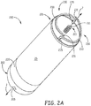
- Figure 2A is a perspective view of an implantable medical device 200, wherein the electrode assembly thereof includes a helical structure 210, which extends distally from a distal portion 201 of device 200, and around a longitudinal axis 2 of the electrode assembly, and on which a first electrode surface is formed, and a ring structure 220, on which a second electrode surface is formed.
- the pair of electrode surfaces can provide bipolar pacing and sensing at either of implant sites 102, 103 shown in Figure 1 .
- both pulse generator electronic circuitry and a battery power source of device 200 are contained within a relatively compact, or miniature, hermetically sealed capsule 25 thereof, for example, that has a length of approximately 2 to 2.5 centimeters and a diameter of approximately 20 French (6 - 7 millimeters).
- Capsule 25 is preferably formed from a biocompatible and biostable metal such as titanium, which is overlaid with an insulative layer, for example, parylene, polyimide, medical grade polyurethane, Polyether ether ketone (PEEK), or silicone.
- Hermetic feedthroughs couple each electrode surface to the pulse generator circuitry contained within capsule 25, which is configured, according to methods known to those skilled in art, to sense, via the electrode surfaces, either atrial depolarization (i.e. P-waves), for example, from implant site 102, or ventricular depolarization (i.e. R-waves), for example, from implant site 103, and to apply stimulation pulses to the myocardial tissue for cardiac pacing when necessary.
- atrial depolarization i.e. P-waves
- R-waves ventricular depolarization
- helical structure 210 is preferably configured for high impedance pacing from the electrode surface thereof; thus, according to an exemplary embodiment, helical structure 210 has an outer diameter of approximately 2 French (0.6 - 0.7 millimeters), and the gross surface area of the electrode surface is between approximately 1 square millimeter and approximately 2 square millimeters. In some embodiments, the electrode surface is formed along an outer portion of helical structure 210, while an inner portion thereof is insulated. Those skilled in the art will appreciate that the high impedance of this electrode surface, resultant of the relatively small gross surface area thereof, provides relatively efficient pacing stimulation, for example, to maximize the life of the battery power source of device 200.
- Helical structure 210 may be formed from a platinum iridium wire or a tantalum wire, for example, having an outer diameter of between approximately 0.005 inch (0.13 mm) and approximately .010 inch (0.25 mm); and the electrode surface of helical structure 210 may be formed by a titanium nitride (TiN) coating that increases the microscopic surface area of the electrode surface for an enhanced interface with the myocardial tissue, for example, at either of implant sites 102, 103.
- Ring structure 220 may likewise be formed of either platinum iridium or tantalum and have a TiN coating that forms the second electrode surface, which may have a surface area of approximately 50 millimeters, according to some embodiments.
- Intimate contact between the electrode surface of helical structure 210 and the myocardial tissue is attained by engaging a piercing distal tip 211 of helical structure 210 in the tissue and then rotating structure 210 counter-clockwise, according to Figure 2A , to screw structure 210 into the tissue.
- the electrode assembly of device 200 further includes one or a pair of fixation members 230.
- FIG. 2A illustrates each fixation member 230 including a tissue engaging portion 233, which is terminated by a piercing distal tip 231, wherein each tissue engaging portion 233 extends from the distal tip 231 thereof, along a circular path, which defines a perimeter in which helical structure 210 is located.
- tissue engaging portion 233 of each fixation member 230 extends along the circular path toward a fixed end, which is coupled to distal portion 201 of device 200, and which includes a post 235 extending distally from distal portion 201.
- Posts 235 are shown located opposite one another on either side of helix structure 210, being radially offset from, and extending approximately parallel with, longitudinal axis 2.
- each tissue engaging portion 233 extends from the corresponding distal tip 231
- helical structure 210 extends from piercing distal tip 211 thereof, which is clockwise according to Figure 2A .
- device 200 as a whole may be rotated, for example, in the counter-clockwise direction, according to Figure 2A (i.e.
- each tissue engaging portion 233 may extend between approximately one quarter of a turn to approximately one full turn around the circular path.
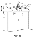
- FIG. 2B is an elevation view of a portion of the electrode assembly of device 200 wherein a contour of each tissue engaging portion 233, according to some embodiments, as it extends along the circular path is more clearly seen.
- Figure 2B illustrates each tissue engaging portion 233 including a first segment 233A, which extends along the circular path and bends proximally from a distal end 41 of the corresponding post 235, toward distal portion 201 of device 200, and a second segment 233B, which extends along the circular path and distally from the corresponding first segment 233A, away from distal portion 201.
- piercing distal tips 231 of fixation members 230 and piercing distal tip 211 of helical structure 210 are coplanar with one another and spaced at a distance T from distal portion 201, wherein distance T may be between approximately 1 millimeter and approximately 3 millimeters.
- a pitch of helical structure 210 e.g., approximately 0.016 inch (0.4064) is less than or equal to that defined by tissue engaging portion 233 between distal end 41 of post 235 and piercing distal tip 231.
- helical structure 210 may extend beyond distal tips 231, so that distal tips 231 are proximally offset from distal tip 211 of helical structure 210, in which case helical structure 210 may engage within tissue at the target implant site ahead of the engagement of one or both of portions 233, depending on the character, or structure of the surface of the tissue at the site, and an orientation of the electrode assembly relative to the surface.
- each tissue engaging portion 233 may be likened to a saddle shape, wherein a gap G between distal portion 201 and tissue engaging portion 233 narrows to a distance N, in between piercing distal tip 231 and post 235, to create a kind of lock on the tissue with which portion 233 is engaged.
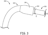
- a delivery device 300 may be configured with an outer sheath 340 and a telescoping inner member 360 that is configured to engage around a proximal portion 202 ( Figure 2A ) of device 200.
- delivery device 300 with device 200 loaded into a distal portion 341 of outer sheath 340, may be inserted into the vascular system of a patient, for example, via a percutaneous entry site, and distal portion 341 passed into the heart, via an inferior vena cava IVC or a superior vena cava SVC thereof.
- inner member 360 may be advanced, relative to outer sheath 340, to push device 200 out from a distal opening of distal portion 341 and into contact with the site, and then inner member 360 may be rotated, per arrow F, to fix device in tissue M at the target implant site.
- device 200 includes a notch 205, which is formed in proximal portion 202 and configured for engagement with a screw-driver type stylet, wherein the tool may replace or form a part of telescoping inner member 360 that rotates device 200 per arrow F.
- an electrode surface may be formed on one or both of fixation members 230 to function as a bipolar pace-sense pair with the above-described electrode surface formed on helical structure 210.
- Such a pace-sense pair may be advantageous in some instances, over the pace-sense pair formed with the electrode surface of ring structure 220, for example, when device 200 is implanted in the right atrium RA for pacing function based on P-wave sensing, since the closer spacing between the electrode surface of helical structure 210 and that of one or both of fixation members 230 is less susceptible to far-field R-wave sensing.
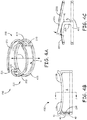
- Figure 4A is a perspective view of a pair 430 of fixation members 230, wherein pair 430 may be machined, or cut, from a tubular member, according to some embodiments.
- Figure 4B is an elevation view of pair 430; and
- Figure 4C is a cross-section view through section line A-A of Figure 4B.
- Figures 4A-C illustrate a coupling portion of each fixation member 230 including the aforementioned post 235 and a base segment 435, which extends from a proximal end 42 of post 235 and along a circular path, which is offset from the above-described circular path along which tissue engaging portions 233 extend.
- base segments 435 may be fixed and embedded within distal portion 201 of device 200, and thus hidden from view in these Figures. It should be noted that, in alternative embodiments, base segments 435 may extend in different paths, either arcuate or relatively straight. But, according to the illustrated embodiment, because pair 430 of fixation members 230 is cut from a tubular member, both circular paths (of tissue securing portions 233 and base segments 435) extend around a longitudinal axis 4 of the tubular member.
- the tubular member from which pair 430 is cut may be any suitable biocompatible and rigid material, preferably a metallic material, for example, titanium or tantalum.
- FIG. 4A-B further illustrates one of posts 235 including an optional extension 45 that protrudes radially outward, away from longitudinal axis 4. Extension 45 may serve as a tissue stop, when tissue engaging portions 233 are being screwed into tissue, for example, as described above.
- Figure 4C illustrates a rectangular cross-section of each base segment 435 and of each tissue engaging portion 233, wherein, according to an exemplary embodiment, the cross section of each tissue engaging portion 233 is approximately 0.005 inch by 0.010 inch (0.127 x 0.254 mm), and may vary slightly in size to enhance a strength thereof.
- Figure 4C further illustrates piercing distal tip 231 of one of tissue engaging portions 233 extending over first segment 233A of the other of portions 233, and spaced apart therefrom by a distance R. According to an exemplary embodiment distance R is approximately 0.018 inch (0.4572 mm).
Landscapes
- Health & Medical Sciences (AREA)
- Engineering & Computer Science (AREA)
- Biomedical Technology (AREA)
- Nuclear Medicine, Radiotherapy & Molecular Imaging (AREA)
- Radiology & Medical Imaging (AREA)
- Life Sciences & Earth Sciences (AREA)
- Animal Behavior & Ethology (AREA)
- General Health & Medical Sciences (AREA)
- Public Health (AREA)
- Veterinary Medicine (AREA)
- Heart & Thoracic Surgery (AREA)
- Cardiology (AREA)
- Vascular Medicine (AREA)
- Electrotherapy Devices (AREA)
Description
- The present invention pertains to implantable medical devices, and, more specifically, to electrode assemblies thereof.
- Many electrode assemblies of implantable medical devices, for the delivery of stimulation therapy and/or for diagnostic sensing, include fixation members configured to hold an electrode surface of the assembly in stable and intimate contact with tissue at an implant site. Those skilled in the art are familiar with electrode assemblies that include a helical structure; the helical structure typically includes a piercing distal tip to engage with tissue so that the helical structure may be screwed into the tissue and thereby fix an electrode surface of the assembly in intimate contact with the tissue. In some of these electrode assemblies the electrode surface is formed directly on the helical structure. Although such a helical structure can provide adequate fixation in many types of electrode assemblies, there is a need for new types of electrode assemblies and associated fixation members.
WO 2009/006531 A1 generally describes methods and systems for minimizing energy utilization for tissue stimulation using implantable microstimulators, and discloses the features according to the preamble of claim 1.WO 2007/073435 A1 4 discloses helical electrodes for intramyocardial pacing and sensing. - Embodiments of the present description encompass implantable medical devices (e.g., cardiac pacemakers), electrode assemblies thereof, and fixation members for the electrode assemblies. According to some embodiments, a fixation member for an electrode assembly, includes a tissue engaging portion that extends along a circular path, between a piercing distal tip thereof and a coupling portion, or a fixed end, of the member, which is configured to be fixedly attached to a distal portion of the device. The circular path extends around a longitudinal axis of the fixation member and of the electrode assembly, and the electrode assembly further includes a helical structure that has an electrode surface formed thereon, and a piercing distal tip adjacent thereto; the helical structure is located within a perimeter of the circular path and also extends around the longitudinal axis. The tissue engaging portion of the fixation member extends from the distal tip thereof in a direction along the circular path that is the same as that in which the helical structure extends from the distal tip thereof. Thus, rotation of the distal portion of the device, when the piercing distal tips of the helical structure and the fixation member are positioned in proximity to a target implant site, causes both the helical structure and the tissue engaging portion of the fixation member to engage within tissue at the implant site.
- An implantable medical device, according to some embodiments, comprises a relatively compact, or miniature capsule in which a pulse generator and power source are hermetically sealed, and to which the electrode assembly is directly coupled. In some embodiments, an outer diameter of the helical structure is approximately 2 French, while an outer diameter defined by the tissue engaging portion of the fixation member is approximately 20 French; and the electrode surface formed on the helical structure is preferably formed for 'high impedance' pacing, for example, having a gross surface area of approximately 1 to 2 square millimeters and an increased microscopic surface area, for example, being formed as a titanium nitride (TiN) coating overlaying the helical structure. According to some embodiments, another electrode surface is formed on the fixation member, for example, to form a bipolar pace-sense pair with the electrode surface formed on the helical structure.
- Electrode assemblies, according to some preferred embodiments, include a pair of the above-described fixation members, for example, wherein the fixed ends thereof are located opposite one another, on either side of the helical structure. The tissue engaging portion of each fixation member may extend between approximately one quarter of a turn and approximately one turn along the circular path, preferably, approximately one half of a turn. The piercing distal tip of each fixation member may be coplanar with that of the helical structure, or proximally offset therefrom.
- In some embodiments, the coupling portion, or fixed end, of the fixation member includes a post that is offset from, and extends approximately parallel with the longitudinal axis, and the tissue engaging portion of the fixation member includes a first segment and a second segment, wherein the first segment extends along the circular path and proximally from the post, in a longitudinal direction, and the second segment extends along the circular path and distally from the first segment to the distal tip, in an opposite longitudinal direction. Thus, the tissue engaging portion, according to these embodiments of the fixation member has a contour that may be likened to a saddle shape, wherein a gap between the distal portion of the device and the tissue engaging portion of the fixation member narrows in between the piercing distal tip thereof and the post of the coupling portion to create a kind of lock on the tissue with which the fixation member is engaged.
- The following drawings are illustrative of particular embodiments of the present description and therefore do not limit the scope of the description. The drawings are not to scale (unless so stated) and are intended for use in conjunction with the explanations in the following detailed description. Embodiments will hereinafter be described in conjunction with the appended drawings wherein like numerals/letters denote like elements, and:
-
Figure 1 is a schematic diagram showing potential implant sites for embodiments of the present description; -
Figure 2A is a perspective view of an implantable medical device, according to some embodiments; -
Figure 2B is an elevation view of a portion of an electrode assembly of the device, according to some embodiments; -
Figures 3 is a plan view of a distal portion of a delivery device engaging the medical device, according to some methods; -
Figure 4A is a perspective view of a pair of fixation members, according to some embodiments; -
Figure 4B is an elevation view of the pair of fixation members; and -
Figure 4C is a cross-section view through section line A-A ofFigure 4B . - The following description provides practical examples, and those skilled in the art will recognize that some of the examples may have suitable alternatives.
-
Figure 1 is a schematic diagram showing the interior of a right atrium RA and a right ventricle RV of a heart.Figure 1 illustrates some potentialendocardial implant sites Figure 2A . It should be noted that any other suitable implant site, either endocardial or epicardial, may be selected for electrode assembly embodiments.Figure 2A is a perspective view of an implantablemedical device 200, wherein the electrode assembly thereof includes ahelical structure 210, which extends distally from adistal portion 201 ofdevice 200, and around alongitudinal axis 2 of the electrode assembly, and on which a first electrode surface is formed, and aring structure 220, on which a second electrode surface is formed. The pair of electrode surfaces can provide bipolar pacing and sensing at either ofimplant sites Figure 1 . According to the illustrated embodiment, both pulse generator electronic circuitry and a battery power source ofdevice 200 are contained within a relatively compact, or miniature, hermetically sealedcapsule 25 thereof, for example, that has a length of approximately 2 to 2.5 centimeters and a diameter of approximately 20 French (6 - 7 millimeters). Capsule 25 is preferably formed from a biocompatible and biostable metal such as titanium, which is overlaid with an insulative layer, for example, parylene, polyimide, medical grade polyurethane, Polyether ether ketone (PEEK), or silicone. Hermetic feedthroughs, such as any known to those skilled in the art, couple each electrode surface to the pulse generator circuitry contained withincapsule 25, which is configured, according to methods known to those skilled in art, to sense, via the electrode surfaces, either atrial depolarization (i.e. P-waves), for example, fromimplant site 102, or ventricular depolarization (i.e. R-waves), for example, fromimplant site 103, and to apply stimulation pulses to the myocardial tissue for cardiac pacing when necessary. - With further reference to
Figure 2A ,helical structure 210 is preferably configured for high impedance pacing from the electrode surface thereof; thus, according to an exemplary embodiment,helical structure 210 has an outer diameter of approximately 2 French (0.6 - 0.7 millimeters), and the gross surface area of the electrode surface is between approximately 1 square millimeter and approximately 2 square millimeters. In some embodiments, the electrode surface is formed along an outer portion ofhelical structure 210, while an inner portion thereof is insulated. Those skilled in the art will appreciate that the high impedance of this electrode surface, resultant of the relatively small gross surface area thereof, provides relatively efficient pacing stimulation, for example, to maximize the life of the battery power source ofdevice 200.Helical structure 210 may be formed from a platinum iridium wire or a tantalum wire, for example, having an outer diameter of between approximately 0.005 inch (0.13 mm) and approximately .010 inch (0.25 mm); and the electrode surface ofhelical structure 210 may be formed by a titanium nitride (TiN) coating that increases the microscopic surface area of the electrode surface for an enhanced interface with the myocardial tissue, for example, at either ofimplant sites Ring structure 220 may likewise be formed of either platinum iridium or tantalum and have a TiN coating that forms the second electrode surface, which may have a surface area of approximately 50 millimeters, according to some embodiments. - Intimate contact between the electrode surface of
helical structure 210 and the myocardial tissue is attained by engaging a piercingdistal tip 211 ofhelical structure 210 in the tissue and then rotatingstructure 210 counter-clockwise, according toFigure 2A , toscrew structure 210 into the tissue. In order to stabilize and maintain this intimate tissue contact of the electrode surface ofhelical structure 210, the electrode assembly ofdevice 200 further includes one or a pair offixation members 230. -
Figure 2A illustrates eachfixation member 230 including atissue engaging portion 233, which is terminated by a piercingdistal tip 231, wherein eachtissue engaging portion 233 extends from thedistal tip 231 thereof, along a circular path, which defines a perimeter in whichhelical structure 210 is located. With further reference toFigure 2A ,tissue engaging portion 233 of eachfixation member 230 extends along the circular path toward a fixed end, which is coupled todistal portion 201 ofdevice 200, and which includes apost 235 extending distally fromdistal portion 201.Posts 235 are shown located opposite one another on either side ofhelix structure 210, being radially offset from, and extending approximately parallel with,longitudinal axis 2. According to the illustrated embodiment, the direction along the circular path, in which eachtissue engaging portion 233 extends from the correspondingdistal tip 231, is the same as in whichhelical structure 210 extends from piercingdistal tip 211 thereof, which is clockwise according toFigure 2A . Thus, according to those embodiments in whichhelical structure 210 is fixedly attached todistal portion 201 ofdevice 200, likefixation members 230, and when piercingdistal tips site 102 or 103) for engagement with myocardial tissue,device 200 as a whole may be rotated, for example, in the counter-clockwise direction, according toFigure 2A (i.e. per arrow F ofFigures 2B and3 ), to screw bothhelical structure 210 andfixation members 230 into the tissue. AlthoughFigure 2A illustrates eachtissue engaging portion 233 extending approximately one half of a turn along the circular path, in alternative embodiments eachportion 233 may extend between approximately one quarter of a turn to approximately one full turn around the circular path. -
Figure 2B is an elevation view of a portion of the electrode assembly ofdevice 200 wherein a contour of eachtissue engaging portion 233, according to some embodiments, as it extends along the circular path is more clearly seen.Figure 2B illustrates eachtissue engaging portion 233 including afirst segment 233A, which extends along the circular path and bends proximally from adistal end 41 of thecorresponding post 235, towarddistal portion 201 ofdevice 200, and asecond segment 233B, which extends along the circular path and distally from the correspondingfirst segment 233A, away fromdistal portion 201. According to the illustrated embodiment, piercingdistal tips 231 offixation members 230 and piercingdistal tip 211 of helical structure 210 (Figure 2A ) are coplanar with one another and spaced at a distance T fromdistal portion 201, wherein distance T may be between approximately 1 millimeter and approximately 3 millimeters. According to some preferred embodiments, a pitch of helical structure 210 (e.g., approximately 0.016 inch (0.4064)) is less than or equal to that defined bytissue engaging portion 233 betweendistal end 41 ofpost 235 and piercingdistal tip 231. According to some alternative embodiments, as illustrated by the broken lines inFigure 2B ,helical structure 210 may extend beyonddistal tips 231, so thatdistal tips 231 are proximally offset fromdistal tip 211 ofhelical structure 210, in which casehelical structure 210 may engage within tissue at the target implant site ahead of the engagement of one or both ofportions 233, depending on the character, or structure of the surface of the tissue at the site, and an orientation of the electrode assembly relative to the surface. With further reference toFigure 2B , in conjunction withFigures 4A-C , the above described contour of eachtissue engaging portion 233 may be likened to a saddle shape, wherein a gap G betweendistal portion 201 andtissue engaging portion 233 narrows to a distance N, in between piercingdistal tip 231 andpost 235, to create a kind of lock on the tissue with whichportion 233 is engaged. - As was mentioned above, in those embodiments wherein both
helical structure 210 and one or a pair offixation members 230 are fixedly attached todistal portion 201 ofdevice 200,device 200 may be rotated to engagehelical structure 210 and fixation member(s) 230 in tissue at a target implant site. With reference toFigure 3 , and according to some implant methods, adelivery device 300 may be configured with anouter sheath 340 and a telescopinginner member 360 that is configured to engage around a proximal portion 202 (Figure 2A ) ofdevice 200. With reference back toFigure 1 ,delivery device 300, withdevice 200 loaded into adistal portion 341 ofouter sheath 340, may be inserted into the vascular system of a patient, for example, via a percutaneous entry site, anddistal portion 341 passed into the heart, via an inferior vena cava IVC or a superior vena cava SVC thereof. Oncedistal portion 341 is located in proximity to a target implant site, for example, one ofsites inner member 360 may be advanced, relative toouter sheath 340, to pushdevice 200 out from a distal opening ofdistal portion 341 and into contact with the site, and theninner member 360 may be rotated, per arrow F, to fix device in tissue M at the target implant site. With reference back toFigure 2A , according to some embodiments,device 200 includes anotch 205, which is formed inproximal portion 202 and configured for engagement with a screw-driver type stylet, wherein the tool may replace or form a part of telescopinginner member 360 that rotatesdevice 200 per arrow F. - It should be noted that, according to some embodiments, an electrode surface may be formed on one or both of
fixation members 230 to function as a bipolar pace-sense pair with the above-described electrode surface formed onhelical structure 210. Such a pace-sense pair may be advantageous in some instances, over the pace-sense pair formed with the electrode surface ofring structure 220, for example, whendevice 200 is implanted in the right atrium RA for pacing function based on P-wave sensing, since the closer spacing between the electrode surface ofhelical structure 210 and that of one or both offixation members 230 is less susceptible to far-field R-wave sensing. -
Figure 4A is a perspective view of apair 430 offixation members 230, whereinpair 430 may be machined, or cut, from a tubular member, according to some embodiments.Figure 4B is an elevation view ofpair 430; andFigure 4C is a cross-section view through section line A-A ofFigure 4B. Figures 4A-C illustrate a coupling portion of eachfixation member 230 including theaforementioned post 235 and abase segment 435, which extends from aproximal end 42 ofpost 235 and along a circular path, which is offset from the above-described circular path along whichtissue engaging portions 233 extend. With reference back toFigures 2A-B ,base segments 435 may be fixed and embedded withindistal portion 201 ofdevice 200, and thus hidden from view in these Figures. It should be noted that, in alternative embodiments,base segments 435 may extend in different paths, either arcuate or relatively straight. But, according to the illustrated embodiment, becausepair 430 offixation members 230 is cut from a tubular member, both circular paths (oftissue securing portions 233 and base segments 435) extend around a longitudinal axis 4 of the tubular member. The tubular member from which pair 430 is cut may be any suitable biocompatible and rigid material, preferably a metallic material, for example, titanium or tantalum. - According to the illustrated embodiment, and with reference to
Figure 4B , in conjunction withFigure 2B , it may be seen that a central cross-section, per section line A-A (aligned on axis 4), dividesfirst segment 233A of eachtissue engaging portion 233 from the correspondingsecond segment 233B and, thus, coincides with the above-described narrowing of gap G.Figures 4A-B further illustrates one ofposts 235 including anoptional extension 45 that protrudes radially outward, away from longitudinal axis 4.Extension 45 may serve as a tissue stop, whentissue engaging portions 233 are being screwed into tissue, for example, as described above. -
Figure 4C illustrates a rectangular cross-section of eachbase segment 435 and of eachtissue engaging portion 233, wherein, according to an exemplary embodiment, the cross section of eachtissue engaging portion 233 is approximately 0.005 inch by 0.010 inch (0.127 x 0.254 mm), and may vary slightly in size to enhance a strength thereof.Figure 4C further illustrates piercingdistal tip 231 of one oftissue engaging portions 233 extending overfirst segment 233A of the other ofportions 233, and spaced apart therefrom by a distance R. According to an exemplary embodiment distance R is approximately 0.018 inch (0.4572 mm). The present invention is set out in the appended claims. The embodiments, aspects or examples according to the present description that do not fall within the scope of said claims are provided for illustrative purposes only and do not form part of the present invention.
Claims (11)
- An implantable medical device comprising a pulse generator, a power source, an hermetically sealed capsule (25) that contains the pulse generator and the power source, and an electrode assembly, the electrode assembly comprising a longitudinal axis (2), a helical structure (210) coupled to the capsule and extending distally from the capsule and around the longitudinal axis in a first direction being either clockwise or counter-clockwise, a first electrode surface formed on the helical structure, and a second electrode surface electrically isolated from the first electrode surface, the helical structure including a piercing distal tip located adjacent the first electrode surface; and characterised by the device comprising at least one fixation member (230), wherein the or each fixation member comprises:a fixed end coupled to the capsule; anda tissue engaging portion (233) terminated by a piercing distal tip (231), each tissue engaging portion extending from the corresponding distal tip to the corresponding fixed end along a circular path around the longitudinal axis, the helical structure being located within a perimeter of the circular path; andwherein each tissue engaging portion extends from the piercing distal tip thereof in a direction along the circular path that is the same as the first direction in which the helical structure extends from the piercing distal tip thereof, either clockwise or counter-clockwise;wherein the fixed end of each fixation member of the electrode assembly comprises a post (235) that extends approximately parallel with the longitudinal axis, between the distal portion of the device and the tissue engaging portion of the corresponding fixation member, andwherein the tissue engaging portion of each fixation member of the electrode assembly includes a first segment (233A) and a second segment (233B), each first segment extending along the circular path and bending proximally from the corresponding post, toward the capsule of the device, and each second segment extending along the circular path and distally from the corresponding first segment, away from the capsule of the device.
- The device of claim 1, wherein the tissue engaging portion of each fixation member of the electrode assembly extends between approximately one quarter of a turn and approximately one turn along the circular path.
- The device of claim 1, wherein the fixed end of each fixation member of the electrode assembly further comprises a base segment from which the corresponding post extends distally to the corresponding tissue engaging portion, the base segment of each fixation member extending along an arcuate path, around the longitudinal axis.
- The device of any of claims 1 - 3, wherein the piercing distal tip of each fixation member of the electrode assembly is approximately coplanar with the piercing distal tip of the helical structure.
- The device of any of claims 1 - 3, wherein the piercing distal tip of each fixation member of the electrode assembly is proximally offset from the piercing distal tip of the helical structure.
- The device of any of claims 1 - 3, wherein the second electrode surface of the electrode assembly is formed on the fixation member of the electrode assembly.
- The device of any of claims 1 - 3, wherein the electrode assembly further comprises a ring structure (220) that extends around a perimeter of the capsule, and the second electrode surface is formed on the ring structure.
- The device of any of claims 1 - 7, wherein the electrode assembly further comprises a third electrode surface formed on the fixation member thereof.
- The device of any of claims 1 - 7 wherein an outer diameter of the helical structure of the electrode assembly is 2 French, and an outer diameter defined by the tissue engaging portion of each fixation member of the electrode assembly is 20 French.
- The device of any of claims 1 - 7, wherein a gross surface area of the first electrode surface is between 1 square millimeter and 2 square millimeters.
- The device of any of claims 1 - 7, wherein the first electrode surface comprises a TiN coating that overlays the helical structure.
Applications Claiming Priority (2)
| Application Number | Priority Date | Filing Date | Title |
|---|---|---|---|
| US13/869,509 US8948883B2 (en) | 2013-04-24 | 2013-04-24 | Electrode assemblies and associated fixation members for implantable medical devices |
| PCT/US2014/034155 WO2014176076A1 (en) | 2013-04-24 | 2014-04-15 | Electrode assemblies and associated fixation members for implantable medical devices |
Publications (2)
| Publication Number | Publication Date |
|---|---|
| EP2988821A1 EP2988821A1 (en) | 2016-03-02 |
| EP2988821B1 true EP2988821B1 (en) | 2018-08-15 |
Family
ID=50732320
Family Applications (1)
| Application Number | Title | Priority Date | Filing Date |
|---|---|---|---|
| EP14724605.2A Active EP2988821B1 (en) | 2013-04-24 | 2014-04-15 | Electrode assemblies and associated fixation members for implantable medical devices |
Country Status (4)
| Country | Link |
|---|---|
| US (2) | US8948883B2 (en) |
| EP (1) | EP2988821B1 (en) |
| CN (1) | CN105142715B (en) |
| WO (1) | WO2014176076A1 (en) |
Cited By (1)
| Publication number | Priority date | Publication date | Assignee | Title |
|---|---|---|---|---|
| US11541243B2 (en) | 2019-03-15 | 2023-01-03 | Pacesetter, Inc. | Biostimulator having coaxial fixation elements |
Families Citing this family (39)
| Publication number | Priority date | Publication date | Assignee | Title |
|---|---|---|---|---|
| US10842993B2 (en) * | 2013-08-16 | 2020-11-24 | Cardiac Pacemakers, Inc. | Leadless cardiac pacing devices |
| WO2016065058A1 (en) | 2014-10-22 | 2016-04-28 | Cardiac Pacemakers, Inc. | Delivery devices for leadless cardiac devices |
| US11278720B2 (en) | 2014-10-22 | 2022-03-22 | Cardiac Pacemakers, Inc. | Delivery devices and methods for leadless cardiac devices |
| US20180056043A1 (en) * | 2016-08-29 | 2018-03-01 | Randolf Von Oepen | Adjustable guidewire receiving member |
| US10238865B2 (en) * | 2016-10-06 | 2019-03-26 | Medtronic, Inc. | Electrode fixation in interventional medical systems |
| US10905465B2 (en) | 2016-11-21 | 2021-02-02 | Cardiac Pacemakers, Inc. | Delivery devices and wall apposition sensing |
| US11198013B2 (en) | 2016-11-21 | 2021-12-14 | Cardiac Pacemakers, Inc. | Catheter and leadless cardiac devices including electrical pathway barrier |
| US10485981B2 (en) | 2016-12-27 | 2019-11-26 | Cardiac Pacemakers, Inc. | Fixation methods for leadless cardiac devices |
| US10722684B2 (en) | 2016-12-27 | 2020-07-28 | Cardiac Pacemakers, Inc. | Leadless delivery catheter with conductive pathway |
| US10806931B2 (en) | 2016-12-27 | 2020-10-20 | Cardiac Pacemakers, Inc. | Delivery devices and methods for leadless cardiac devices |
| EP3562545B1 (en) | 2016-12-27 | 2023-11-08 | Cardiac Pacemakers, Inc. | Delivery devices and methods for leadless cardiac devices |
| US10773089B2 (en) | 2017-01-26 | 2020-09-15 | Cardiac Pacemakers, Inc. | Delivery devices and methods for leadless cardiac devices |
| CN110418661B (en) | 2017-03-10 | 2024-01-02 | 心脏起搏器股份公司 | Fixing piece for leadless cardiac device |
| US10737092B2 (en) | 2017-03-30 | 2020-08-11 | Cardiac Pacemakers, Inc. | Delivery devices and methods for leadless cardiac devices |
| US11577085B2 (en) | 2017-08-03 | 2023-02-14 | Cardiac Pacemakers, Inc. | Delivery devices and methods for leadless cardiac devices |
| US10758733B2 (en) | 2017-09-15 | 2020-09-01 | Medtronic, Inc. | Implantable medical device with retractable fixation sheath |
| US11478653B2 (en) | 2017-09-15 | 2022-10-25 | Medtronic, Inc. | Electrodes for intra-cardiac pacemaker |
| WO2019090256A1 (en) | 2017-11-06 | 2019-05-09 | Pacesetter, Inc. | Biostimulator having fixation element |
| EP3768160B1 (en) | 2018-03-23 | 2023-06-07 | Medtronic, Inc. | Vfa cardiac therapy for tachycardia |
| US11235159B2 (en) | 2018-03-23 | 2022-02-01 | Medtronic, Inc. | VFA cardiac resynchronization therapy |
| JP2021518208A (en) | 2018-03-23 | 2021-08-02 | メドトロニック,インコーポレイテッド | AV Synchronized VfA Cardiac Treatment |
| US11577086B2 (en) | 2018-08-20 | 2023-02-14 | Pacesetter, Inc. | Fixation mechanisms for a leadless cardiac biostimulator |
| CN112770807A (en) | 2018-09-26 | 2021-05-07 | 美敦力公司 | Capture in atrial-to-ventricular cardiac therapy |
| US11951313B2 (en) | 2018-11-17 | 2024-04-09 | Medtronic, Inc. | VFA delivery systems and methods |
| US11679265B2 (en) | 2019-02-14 | 2023-06-20 | Medtronic, Inc. | Lead-in-lead systems and methods for cardiac therapy |
| USD894396S1 (en) | 2019-03-08 | 2020-08-25 | Pacesetter, Inc. | Leadless biostimulator attachment feature |
| WO2020205397A1 (en) | 2019-03-29 | 2020-10-08 | Cardiac Pacemakers, Inc. | Systems and methods for treating cardiac arrhythmias |
| CN113660977A (en) | 2019-03-29 | 2021-11-16 | 心脏起搏器股份公司 | System and method for treating cardiac arrhythmias |
| US11697025B2 (en) | 2019-03-29 | 2023-07-11 | Medtronic, Inc. | Cardiac conduction system capture |
| US11213676B2 (en) | 2019-04-01 | 2022-01-04 | Medtronic, Inc. | Delivery systems for VfA cardiac therapy |
| US11712188B2 (en) | 2019-05-07 | 2023-08-01 | Medtronic, Inc. | Posterior left bundle branch engagement |
| US11541232B2 (en) | 2019-06-18 | 2023-01-03 | Medtronic, Inc. | Electrode configuration for a medical device |
| US11305127B2 (en) | 2019-08-26 | 2022-04-19 | Medtronic Inc. | VfA delivery and implant region detection |
| WO2021050679A1 (en) | 2019-09-11 | 2021-03-18 | Cardiac Pacemakers, Inc. | Tools and systems for implanting and/or retrieving a leadless cardiac pacing device with helix fixation |
| WO2021050685A1 (en) | 2019-09-11 | 2021-03-18 | Cardiac Pacemakers, Inc. | Tools and systems for implanting and/or retrieving a leadless cardiac pacing device with helix fixation |
| US11813466B2 (en) | 2020-01-27 | 2023-11-14 | Medtronic, Inc. | Atrioventricular nodal stimulation |
| US11911168B2 (en) | 2020-04-03 | 2024-02-27 | Medtronic, Inc. | Cardiac conduction system therapy benefit determination |
| US11813464B2 (en) | 2020-07-31 | 2023-11-14 | Medtronic, Inc. | Cardiac conduction system evaluation |
| WO2022152585A1 (en) * | 2021-01-15 | 2022-07-21 | Biotronik Se & Co. Kg | Implantable medical device |
Family Cites Families (13)
| Publication number | Priority date | Publication date | Assignee | Title |
|---|---|---|---|---|
| US4355642A (en) * | 1980-11-14 | 1982-10-26 | Physio-Control Corporation | Multipolar electrode for body tissue |
| US5443492A (en) | 1994-02-02 | 1995-08-22 | Medtronic, Inc. | Medical electrical lead and introducer system for implantable pulse generator |
| US5439484A (en) * | 1994-04-21 | 1995-08-08 | Medtronic, Inc. | Defibrillator employing transvenous and subcutaneous electrodes |
| US7212870B1 (en) | 2004-09-16 | 2007-05-01 | Pacesetter, Inc. | Dual helix active fixation stimulation lead |
| CN103381284B (en) | 2005-10-14 | 2017-03-01 | 内诺斯蒂姆股份有限公司 | Leadless cardiac pacemaker and system |
| WO2007073435A1 (en) | 2005-12-22 | 2007-06-28 | Mayo Foundation For Medical Education And Research | Helical electrodes for intramyocardial pacing and sensing |
| EP2674191B1 (en) | 2007-04-25 | 2014-10-29 | St. Jude Medical AB | A medical implantable lead with dual helix |
| WO2009006531A1 (en) | 2007-07-03 | 2009-01-08 | Ebr Systems, Inc. | Minimization of tissue stimulation energy using a microstimulator |
| EP2254663B1 (en) | 2008-02-07 | 2012-08-01 | Cardiac Pacemakers, Inc. | Wireless tissue electrostimulation |
| WO2010088687A1 (en) | 2009-02-02 | 2010-08-05 | Nanostim, Inc. | Leadless cardiac pacemaker with secondary fixation capability |
| EP2394695B1 (en) | 2010-06-14 | 2012-09-26 | Sorin CRM SAS | Standalone intracardiac capsule and implantation accessory |
| CN202236888U (en) * | 2011-07-28 | 2012-05-30 | 陕西秦明医学仪器股份有限公司 | Implanted type double-cavity cardiac pacemaker |
| CN102824197B (en) * | 2012-09-21 | 2017-11-17 | 复旦大学附属华山医院 | A kind of stem cell transplantation screw electrode for left ventricle |
-
2013
- 2013-04-24 US US13/869,509 patent/US8948883B2/en active Active
-
2014
- 2014-04-15 WO PCT/US2014/034155 patent/WO2014176076A1/en active Application Filing
- 2014-04-15 CN CN201480022867.5A patent/CN105142715B/en active Active
- 2014-04-15 EP EP14724605.2A patent/EP2988821B1/en active Active
-
2015
- 2015-02-02 US US14/611,838 patent/US9517336B2/en active Active
Non-Patent Citations (1)
| Title |
|---|
| None * |
Cited By (1)
| Publication number | Priority date | Publication date | Assignee | Title |
|---|---|---|---|---|
| US11541243B2 (en) | 2019-03-15 | 2023-01-03 | Pacesetter, Inc. | Biostimulator having coaxial fixation elements |
Also Published As
| Publication number | Publication date |
|---|---|
| CN105142715B (en) | 2017-11-07 |
| CN105142715A (en) | 2015-12-09 |
| US20140324145A1 (en) | 2014-10-30 |
| US9517336B2 (en) | 2016-12-13 |
| WO2014176076A1 (en) | 2014-10-30 |
| EP2988821A1 (en) | 2016-03-02 |
| US8948883B2 (en) | 2015-02-03 |
| US20150151117A1 (en) | 2015-06-04 |
Similar Documents
| Publication | Publication Date | Title |
|---|---|---|
| EP2988821B1 (en) | Electrode assemblies and associated fixation members for implantable medical devices | |
| US20230023767A1 (en) | Tube-cut helical fixation anchor for electrotherapy device | |
| US7657325B2 (en) | Implantable medical lead including a helical fixation member | |
| US8219213B2 (en) | Active fixation cardiac vein medical lead | |
| US6505082B1 (en) | Single pass lead system | |
| US6931285B2 (en) | Drive shaft seal for a medical electrical lead | |
| US20150088155A1 (en) | Mechanical configurations for a multi-site leadless pacemaker | |
| US11541232B2 (en) | Electrode configuration for a medical device | |
| US9192317B2 (en) | Implantable active fixation lead with biodegradable helical tip | |
| US11975206B2 (en) | Multi-electrode implantable medical device (IMD) | |
| CN112714662A (en) | Bundle of his leads with extendable electrodes and repositioning features | |
| US8543224B2 (en) | Active fixation lead with helix securement mechanism | |
| WO1999030772A2 (en) | Lead system | |
| WO2023230214A1 (en) | Implantable apparatus having helix fixation with varying cross-section | |
| WO2024023622A1 (en) | Medical device fixation with anti-rotation feature | |
| WO2023088766A1 (en) | Implantable medical device comprising an electrode device having a helix element |
Legal Events
| Date | Code | Title | Description |
|---|---|---|---|
| PUAI | Public reference made under article 153(3) epc to a published international application that has entered the european phase |
Free format text: ORIGINAL CODE: 0009012 |
|
| 17P | Request for examination filed |
Effective date: 20151118 |
|
| AK | Designated contracting states |
Kind code of ref document: A1 Designated state(s): AL AT BE BG CH CY CZ DE DK EE ES FI FR GB GR HR HU IE IS IT LI LT LU LV MC MK MT NL NO PL PT RO RS SE SI SK SM TR |
|
| AX | Request for extension of the european patent |
Extension state: BA ME |
|
| DAX | Request for extension of the european patent (deleted) | ||
| STAA | Information on the status of an ep patent application or granted ep patent |
Free format text: STATUS: EXAMINATION IS IN PROGRESS |
|
| 17Q | First examination report despatched |
Effective date: 20170227 |
|
| GRAP | Despatch of communication of intention to grant a patent |
Free format text: ORIGINAL CODE: EPIDOSNIGR1 |
|
| STAA | Information on the status of an ep patent application or granted ep patent |
Free format text: STATUS: GRANT OF PATENT IS INTENDED |
|
| INTG | Intention to grant announced |
Effective date: 20180228 |
|
| GRAS | Grant fee paid |
Free format text: ORIGINAL CODE: EPIDOSNIGR3 |
|
| GRAA | (expected) grant |
Free format text: ORIGINAL CODE: 0009210 |
|
| STAA | Information on the status of an ep patent application or granted ep patent |
Free format text: STATUS: THE PATENT HAS BEEN GRANTED |
|
| AK | Designated contracting states |
Kind code of ref document: B1 Designated state(s): AL AT BE BG CH CY CZ DE DK EE ES FI FR GB GR HR HU IE IS IT LI LT LU LV MC MK MT NL NO PL PT RO RS SE SI SK SM TR |
|
| REG | Reference to a national code |
Ref country code: CH Ref legal event code: EP Ref country code: GB Ref legal event code: FG4D Ref country code: AT Ref legal event code: REF Ref document number: 1029054 Country of ref document: AT Kind code of ref document: T Effective date: 20180815 |
|
| REG | Reference to a national code |
Ref country code: IE Ref legal event code: FG4D |
|
| REG | Reference to a national code |
Ref country code: DE Ref legal event code: R096 Ref document number: 602014030445 Country of ref document: DE |
|
| REG | Reference to a national code |
Ref country code: NL Ref legal event code: MP Effective date: 20180815 |
|
| REG | Reference to a national code |
Ref country code: LT Ref legal event code: MG4D |
|
| REG | Reference to a national code |
Ref country code: AT Ref legal event code: MK05 Ref document number: 1029054 Country of ref document: AT Kind code of ref document: T Effective date: 20180815 |
|
| PG25 | Lapsed in a contracting state [announced via postgrant information from national office to epo] |
Ref country code: IS Free format text: LAPSE BECAUSE OF FAILURE TO SUBMIT A TRANSLATION OF THE DESCRIPTION OR TO PAY THE FEE WITHIN THE PRESCRIBED TIME-LIMIT Effective date: 20181215 Ref country code: RS Free format text: LAPSE BECAUSE OF FAILURE TO SUBMIT A TRANSLATION OF THE DESCRIPTION OR TO PAY THE FEE WITHIN THE PRESCRIBED TIME-LIMIT Effective date: 20180815 Ref country code: BG Free format text: LAPSE BECAUSE OF FAILURE TO SUBMIT A TRANSLATION OF THE DESCRIPTION OR TO PAY THE FEE WITHIN THE PRESCRIBED TIME-LIMIT Effective date: 20181115 Ref country code: SE Free format text: LAPSE BECAUSE OF FAILURE TO SUBMIT A TRANSLATION OF THE DESCRIPTION OR TO PAY THE FEE WITHIN THE PRESCRIBED TIME-LIMIT Effective date: 20180815 Ref country code: NL Free format text: LAPSE BECAUSE OF FAILURE TO SUBMIT A TRANSLATION OF THE DESCRIPTION OR TO PAY THE FEE WITHIN THE PRESCRIBED TIME-LIMIT Effective date: 20180815 Ref country code: LT Free format text: LAPSE BECAUSE OF FAILURE TO SUBMIT A TRANSLATION OF THE DESCRIPTION OR TO PAY THE FEE WITHIN THE PRESCRIBED TIME-LIMIT Effective date: 20180815 Ref country code: FI Free format text: LAPSE BECAUSE OF FAILURE TO SUBMIT A TRANSLATION OF THE DESCRIPTION OR TO PAY THE FEE WITHIN THE PRESCRIBED TIME-LIMIT Effective date: 20180815 Ref country code: GR Free format text: LAPSE BECAUSE OF FAILURE TO SUBMIT A TRANSLATION OF THE DESCRIPTION OR TO PAY THE FEE WITHIN THE PRESCRIBED TIME-LIMIT Effective date: 20181116 Ref country code: NO Free format text: LAPSE BECAUSE OF FAILURE TO SUBMIT A TRANSLATION OF THE DESCRIPTION OR TO PAY THE FEE WITHIN THE PRESCRIBED TIME-LIMIT Effective date: 20181115 Ref country code: AT Free format text: LAPSE BECAUSE OF FAILURE TO SUBMIT A TRANSLATION OF THE DESCRIPTION OR TO PAY THE FEE WITHIN THE PRESCRIBED TIME-LIMIT Effective date: 20180815 |
|
| PG25 | Lapsed in a contracting state [announced via postgrant information from national office to epo] |
Ref country code: HR Free format text: LAPSE BECAUSE OF FAILURE TO SUBMIT A TRANSLATION OF THE DESCRIPTION OR TO PAY THE FEE WITHIN THE PRESCRIBED TIME-LIMIT Effective date: 20180815 Ref country code: LV Free format text: LAPSE BECAUSE OF FAILURE TO SUBMIT A TRANSLATION OF THE DESCRIPTION OR TO PAY THE FEE WITHIN THE PRESCRIBED TIME-LIMIT Effective date: 20180815 Ref country code: AL Free format text: LAPSE BECAUSE OF FAILURE TO SUBMIT A TRANSLATION OF THE DESCRIPTION OR TO PAY THE FEE WITHIN THE PRESCRIBED TIME-LIMIT Effective date: 20180815 |
|
| PG25 | Lapsed in a contracting state [announced via postgrant information from national office to epo] |
Ref country code: IT Free format text: LAPSE BECAUSE OF FAILURE TO SUBMIT A TRANSLATION OF THE DESCRIPTION OR TO PAY THE FEE WITHIN THE PRESCRIBED TIME-LIMIT Effective date: 20180815 Ref country code: RO Free format text: LAPSE BECAUSE OF FAILURE TO SUBMIT A TRANSLATION OF THE DESCRIPTION OR TO PAY THE FEE WITHIN THE PRESCRIBED TIME-LIMIT Effective date: 20180815 Ref country code: CZ Free format text: LAPSE BECAUSE OF FAILURE TO SUBMIT A TRANSLATION OF THE DESCRIPTION OR TO PAY THE FEE WITHIN THE PRESCRIBED TIME-LIMIT Effective date: 20180815 Ref country code: EE Free format text: LAPSE BECAUSE OF FAILURE TO SUBMIT A TRANSLATION OF THE DESCRIPTION OR TO PAY THE FEE WITHIN THE PRESCRIBED TIME-LIMIT Effective date: 20180815 Ref country code: ES Free format text: LAPSE BECAUSE OF FAILURE TO SUBMIT A TRANSLATION OF THE DESCRIPTION OR TO PAY THE FEE WITHIN THE PRESCRIBED TIME-LIMIT Effective date: 20180815 Ref country code: PL Free format text: LAPSE BECAUSE OF FAILURE TO SUBMIT A TRANSLATION OF THE DESCRIPTION OR TO PAY THE FEE WITHIN THE PRESCRIBED TIME-LIMIT Effective date: 20180815 |
|
| REG | Reference to a national code |
Ref country code: DE Ref legal event code: R097 Ref document number: 602014030445 Country of ref document: DE |
|
| PG25 | Lapsed in a contracting state [announced via postgrant information from national office to epo] |
Ref country code: SK Free format text: LAPSE BECAUSE OF FAILURE TO SUBMIT A TRANSLATION OF THE DESCRIPTION OR TO PAY THE FEE WITHIN THE PRESCRIBED TIME-LIMIT Effective date: 20180815 Ref country code: SM Free format text: LAPSE BECAUSE OF FAILURE TO SUBMIT A TRANSLATION OF THE DESCRIPTION OR TO PAY THE FEE WITHIN THE PRESCRIBED TIME-LIMIT Effective date: 20180815 Ref country code: DK Free format text: LAPSE BECAUSE OF FAILURE TO SUBMIT A TRANSLATION OF THE DESCRIPTION OR TO PAY THE FEE WITHIN THE PRESCRIBED TIME-LIMIT Effective date: 20180815 |
|
| PLBE | No opposition filed within time limit |
Free format text: ORIGINAL CODE: 0009261 |
|
| STAA | Information on the status of an ep patent application or granted ep patent |
Free format text: STATUS: NO OPPOSITION FILED WITHIN TIME LIMIT |
|
| 26N | No opposition filed |
Effective date: 20190516 |
|
| PG25 | Lapsed in a contracting state [announced via postgrant information from national office to epo] |
Ref country code: SI Free format text: LAPSE BECAUSE OF FAILURE TO SUBMIT A TRANSLATION OF THE DESCRIPTION OR TO PAY THE FEE WITHIN THE PRESCRIBED TIME-LIMIT Effective date: 20180815 |
|
| REG | Reference to a national code |
Ref country code: CH Ref legal event code: PL |
|
| REG | Reference to a national code |
Ref country code: BE Ref legal event code: MM Effective date: 20190430 |
|
| GBPC | Gb: european patent ceased through non-payment of renewal fee |
Effective date: 20190415 |
|
| PG25 | Lapsed in a contracting state [announced via postgrant information from national office to epo] |
Ref country code: MC Free format text: LAPSE BECAUSE OF FAILURE TO SUBMIT A TRANSLATION OF THE DESCRIPTION OR TO PAY THE FEE WITHIN THE PRESCRIBED TIME-LIMIT Effective date: 20180815 Ref country code: LU Free format text: LAPSE BECAUSE OF NON-PAYMENT OF DUE FEES Effective date: 20190415 |
|
| PG25 | Lapsed in a contracting state [announced via postgrant information from national office to epo] |
Ref country code: GB Free format text: LAPSE BECAUSE OF NON-PAYMENT OF DUE FEES Effective date: 20190415 Ref country code: LI Free format text: LAPSE BECAUSE OF NON-PAYMENT OF DUE FEES Effective date: 20190430 Ref country code: CH Free format text: LAPSE BECAUSE OF NON-PAYMENT OF DUE FEES Effective date: 20190430 |
|
| PG25 | Lapsed in a contracting state [announced via postgrant information from national office to epo] |
Ref country code: BE Free format text: LAPSE BECAUSE OF NON-PAYMENT OF DUE FEES Effective date: 20190430 |
|
| PG25 | Lapsed in a contracting state [announced via postgrant information from national office to epo] |
Ref country code: TR Free format text: LAPSE BECAUSE OF FAILURE TO SUBMIT A TRANSLATION OF THE DESCRIPTION OR TO PAY THE FEE WITHIN THE PRESCRIBED TIME-LIMIT Effective date: 20180815 |
|
| PG25 | Lapsed in a contracting state [announced via postgrant information from national office to epo] |
Ref country code: IE Free format text: LAPSE BECAUSE OF NON-PAYMENT OF DUE FEES Effective date: 20190415 |
|
| PG25 | Lapsed in a contracting state [announced via postgrant information from national office to epo] |
Ref country code: PT Free format text: LAPSE BECAUSE OF FAILURE TO SUBMIT A TRANSLATION OF THE DESCRIPTION OR TO PAY THE FEE WITHIN THE PRESCRIBED TIME-LIMIT Effective date: 20181215 |
|
| PG25 | Lapsed in a contracting state [announced via postgrant information from national office to epo] |
Ref country code: CY Free format text: LAPSE BECAUSE OF FAILURE TO SUBMIT A TRANSLATION OF THE DESCRIPTION OR TO PAY THE FEE WITHIN THE PRESCRIBED TIME-LIMIT Effective date: 20180815 |
|
| PG25 | Lapsed in a contracting state [announced via postgrant information from national office to epo] |
Ref country code: HU Free format text: LAPSE BECAUSE OF FAILURE TO SUBMIT A TRANSLATION OF THE DESCRIPTION OR TO PAY THE FEE WITHIN THE PRESCRIBED TIME-LIMIT; INVALID AB INITIO Effective date: 20140415 Ref country code: MT Free format text: LAPSE BECAUSE OF FAILURE TO SUBMIT A TRANSLATION OF THE DESCRIPTION OR TO PAY THE FEE WITHIN THE PRESCRIBED TIME-LIMIT Effective date: 20180815 |
|
| PG25 | Lapsed in a contracting state [announced via postgrant information from national office to epo] |
Ref country code: MK Free format text: LAPSE BECAUSE OF FAILURE TO SUBMIT A TRANSLATION OF THE DESCRIPTION OR TO PAY THE FEE WITHIN THE PRESCRIBED TIME-LIMIT Effective date: 20180815 |
|
| PGFP | Annual fee paid to national office [announced via postgrant information from national office to epo] |
Ref country code: FR Payment date: 20230321 Year of fee payment: 10 |
|
| PGFP | Annual fee paid to national office [announced via postgrant information from national office to epo] |
Ref country code: DE Payment date: 20230321 Year of fee payment: 10 |