EP2987663B1 - Driver assistance system for a commercial vehicle trailer assembly and method for performing a coupling procedure - Google Patents
Driver assistance system for a commercial vehicle trailer assembly and method for performing a coupling procedure Download PDFInfo
- Publication number
- EP2987663B1 EP2987663B1 EP15000914.0A EP15000914A EP2987663B1 EP 2987663 B1 EP2987663 B1 EP 2987663B1 EP 15000914 A EP15000914 A EP 15000914A EP 2987663 B1 EP2987663 B1 EP 2987663B1
- Authority
- EP
- European Patent Office
- Prior art keywords
- coupling
- semitrailer
- assistance system
- driver assistance
- driver
- Prior art date
- Legal status (The legal status is an assumption and is not a legal conclusion. Google has not performed a legal analysis and makes no representation as to the accuracy of the status listed.)
- Active
Links
- 238000010168 coupling process Methods 0.000 title claims description 117
- 230000008878 coupling Effects 0.000 title claims description 103
- 238000005859 coupling reaction Methods 0.000 title claims description 103
- 238000000034 method Methods 0.000 title claims description 16
- 238000012545 processing Methods 0.000 claims description 12
- 230000008569 process Effects 0.000 claims description 10
- 230000003287 optical effect Effects 0.000 claims description 7
- 238000013459 approach Methods 0.000 claims description 6
- 238000003780 insertion Methods 0.000 claims description 5
- 230000037431 insertion Effects 0.000 claims description 5
- 238000011156 evaluation Methods 0.000 claims description 3
- 238000012800 visualization Methods 0.000 claims description 3
- 239000003550 marker Substances 0.000 description 5
- 238000006073 displacement reaction Methods 0.000 description 4
- 230000006978 adaptation Effects 0.000 description 3
- 238000001514 detection method Methods 0.000 description 2
- 238000011161 development Methods 0.000 description 2
- 238000007689 inspection Methods 0.000 description 2
- 241001136792 Alle Species 0.000 description 1
- 230000004913 activation Effects 0.000 description 1
- 230000009849 deactivation Effects 0.000 description 1
- 230000001419 dependent effect Effects 0.000 description 1
- 238000013461 design Methods 0.000 description 1
- 230000006872 improvement Effects 0.000 description 1
- 230000008685 targeting Effects 0.000 description 1
- 230000000007 visual effect Effects 0.000 description 1
Images


Classifications
-
- B—PERFORMING OPERATIONS; TRANSPORTING
- B60—VEHICLES IN GENERAL
- B60R—VEHICLES, VEHICLE FITTINGS, OR VEHICLE PARTS, NOT OTHERWISE PROVIDED FOR
- B60R1/00—Optical viewing arrangements; Real-time viewing arrangements for drivers or passengers using optical image capturing systems, e.g. cameras or video systems specially adapted for use in or on vehicles
- B60R1/20—Real-time viewing arrangements for drivers or passengers using optical image capturing systems, e.g. cameras or video systems specially adapted for use in or on vehicles
- B60R1/22—Real-time viewing arrangements for drivers or passengers using optical image capturing systems, e.g. cameras or video systems specially adapted for use in or on vehicles for viewing an area outside the vehicle, e.g. the exterior of the vehicle
- B60R1/23—Real-time viewing arrangements for drivers or passengers using optical image capturing systems, e.g. cameras or video systems specially adapted for use in or on vehicles for viewing an area outside the vehicle, e.g. the exterior of the vehicle with a predetermined field of view
- B60R1/26—Real-time viewing arrangements for drivers or passengers using optical image capturing systems, e.g. cameras or video systems specially adapted for use in or on vehicles for viewing an area outside the vehicle, e.g. the exterior of the vehicle with a predetermined field of view to the rear of the vehicle
-
- B—PERFORMING OPERATIONS; TRANSPORTING
- B60—VEHICLES IN GENERAL
- B60D—VEHICLE CONNECTIONS
- B60D1/00—Traction couplings; Hitches; Draw-gear; Towing devices
- B60D1/58—Auxiliary devices
- B60D1/62—Auxiliary devices involving supply lines, electric circuits, or the like
-
- B—PERFORMING OPERATIONS; TRANSPORTING
- B60—VEHICLES IN GENERAL
- B60D—VEHICLE CONNECTIONS
- B60D1/00—Traction couplings; Hitches; Draw-gear; Towing devices
- B60D1/01—Traction couplings or hitches characterised by their type
- B60D1/015—Fifth wheel couplings
-
- B—PERFORMING OPERATIONS; TRANSPORTING
- B60—VEHICLES IN GENERAL
- B60D—VEHICLE CONNECTIONS
- B60D1/00—Traction couplings; Hitches; Draw-gear; Towing devices
- B60D1/24—Traction couplings; Hitches; Draw-gear; Towing devices characterised by arrangements for particular functions
- B60D1/36—Traction couplings; Hitches; Draw-gear; Towing devices characterised by arrangements for particular functions for facilitating connection, e.g. hitch catchers, visual guide means, signalling aids
-
- B—PERFORMING OPERATIONS; TRANSPORTING
- B60—VEHICLES IN GENERAL
- B60R—VEHICLES, VEHICLE FITTINGS, OR VEHICLE PARTS, NOT OTHERWISE PROVIDED FOR
- B60R2300/00—Details of viewing arrangements using cameras and displays, specially adapted for use in a vehicle
- B60R2300/80—Details of viewing arrangements using cameras and displays, specially adapted for use in a vehicle characterised by the intended use of the viewing arrangement
- B60R2300/808—Details of viewing arrangements using cameras and displays, specially adapted for use in a vehicle characterised by the intended use of the viewing arrangement for facilitating docking to a trailer
Description
Die Erfindung betrifft ein Fahrerassistenzsystem eines Nutzfahrzeuggespanns nach dem Oberbegriff des Anspruchs 1 sowie ein Verfahren zur Durchführung eines Ankuppelvorgangs nach dem Oberbegriff des Anspruchs 15.The invention relates to a driver assistance system of a utility vehicle combination according to the preamble of claim 1 and to a method for carrying out a coupling process according to the preamble of
Nutzfahrzeuggespanne sind in zwei grundsätzlich bezüglich ihrer Kupplung unterschiedlichen Ausführungen bekannt. Ein Nutzfahrzeuggespann als Sattelzug besteht aus einem Zugfahrzeug und einem Auflieger. Ein Nutzfahrzeuggespann als Gliederzug besteht dagegen aus einem Zugfahrzeug und einem Anhänger. Beide Ausführungsformen weisen jeweils eine Kupplungsvorrichtung auf, mit einem zugfahrzeugseitigen, verriegelbaren Kupplungs-Aufnahmeteil und einem zugeordneten, in das Kupplungs-Aufnahmeteil einfahrbaren Kuppelelement am Auflieger/ Anhänger.Commercial vehicle combinations are known in two different versions with respect to their coupling. A commercial vehicle combination as a semitrailer consists of a towing vehicle and a semi-trailer. A commercial vehicle combination as an articulated train, however, consists of a towing vehicle and a trailer. Both embodiments each have a coupling device, with a zugfahrzeugseitigen, lockable coupling receiving part and an associated, retractable into the coupling receiving part coupling element on the trailer / trailer.
Bei einem Sattelzug ist das zugfahrzeugseitige Kupplungs-Aufnahmeteil eine bekannte Kupplungsplatte mit einem nach hinten offenen Einfahrschlitz und einem Kupplungsschloss und das aufliegerseitige Kuppelelement ist ein von einer Aufliegerplatte nach unten abragender Zugsattelzapfen als sogenannter Königszapfen.In a tractor-trailer, the towing vehicle-side coupling-receiving part is a known coupling plate with a rearwardly open Einfahrschlitz and a coupling lock and the semi-trailer coupling element is a of a trailer plate downwardly projecting kingpins as a so-called kingpin.
Bei einem Gliederzug ist das zugfahrzeugseitige Kupplungs-Aufnahmeteil meist als an sich bekannte Maulkupplung mit einem nach hinten offenen Fangmaulbereich ausgebildet und das anhängerseitige Kuppelelement besteht aus einer Zugöse an einer Deichsel des Anhängers.In an articulated train, the towing vehicle-side coupling receiving part is usually designed as known per se with a jaw opening open to the rear and the trailer-side coupling element consists of a drawbar eye on a drawbar of the trailer.
Weiter ist es bekannt, solche Nutzfahrzeuggespanne zugfahrzeugseitig mit wenigstens einer Rückfahrkamera als Videokamera auszurüsten mit einem zugeordneten Bildschirm für ein Videobild im Sichtbereich eines Fahrers.It is also known to equipe such utility vehicle combinations with at least one reversing camera as video camera with an associated screen for a video image in the field of vision of a driver.
Solche Videokameras werden sowohl als Rangierhilfen als auch zur Erkennung von Hindernissen im Umfeld des Nutzfahrzeuggespanns, insbesondere in Totwinkelbereichen verwendet. Damit können auch Personen, insbesondere Fußgänger und Radfahrer deutlich erkannt werden, die sich in sicherheitskritischen, nicht mit Außenspiegeln einsehbaren Bereichen im Umfeld des Nutzfahrzeuggespanns befinden. Solche Videokameras sind somit zur Unterstützung des Fahrers beim Fahrbetrieb des zusammengekoppelten Nutzfahrzeuggespanns bestimmt und dadurch regelmäßig seitlich und hoch, beispielsweise auch als "Bird-View"-Kameras am Zugfahrzeug angeordnet. Eine wirksame Unterstützung des Fahrers beim Ankuppelvorgang ist mit diesen Videokameras schon wegen der ungeeigneten Perspektive nicht möglich, da damit weder der Einfahrbereich für das Kuppelelement am Kupplungs-Aufnahmeteil noch das Kuppelelement selbst geeignet erfasst und im Videobild abgebildet wird.Such video cameras are used both as maneuvering aids and for the detection of obstacles in the vicinity of the utility vehicle combination, in particular in blind spot areas. This also clearly recognizes persons, in particular pedestrians and cyclists, who are located in safety-critical areas, which are not visible with exterior mirrors, in the vicinity of the utility vehicle combination. Such video cameras are thus intended to assist the driver in driving the coupled utility vehicle combination and thereby regularly arranged laterally and high, for example, as a "bird-view" cameras on towing vehicle. Effective support of the driver during the coupling process is not possible with these video cameras because of the inappropriate perspective, since neither the retracting area for the coupling element on the coupling receiving part nor the coupling element itself is appropriately detected and imaged in the video image.
Der Ankuppelvorgang bei einem Nutzfahrzeuggespann ist bisher eine aufwendige Maßnahme für den Fahrer, da beim Zurücksetzen des Zugfahrzeugs die beiden zugeordneten Kupplungsteile am Zugfahrzeug und Auflieger/Anhänger, insbesondere durch Peilen über die Außenspiegel gegebenenfalls unterstützt durch mehrere Kontrollgänge, in der Horizontale und in der Höhe zusammengeführt werden müssen. Da Zugfahrzeuggespanne meist nur mit einem Fahrer bewegt werden, steht regelmäßig eine einweisende Hilfsperson nicht zur Verfügung. Ein Ankuppelvorgang kann somit zeitaufwendig mit mehreren Fehlversuchen sein.The Ankuppelvorgang in a commercial vehicle combination is previously a costly measure for the driver, since when resetting the towing vehicle, the two associated coupling parts on towing vehicle and semi-trailer / trailer, in particular by aligning over the mirrors optionally supported by several inspection gears, merged in the horizontal and in height Need to become. Since towing vehicle teams are usually only moved with one driver, a guiding helper is not available on a regular basis. An Ankuppelvorgang can thus be time consuming with multiple failed attempts.
Aus der
Die weitere
Aufgabe der Erfindung ist es, ein Fahrerassistenzsystem eines Nutzfahrzeuggespanns vorzuschlagen, mit dem ein Ankuppelvorgang sicher, schnell und bequem durchführbar ist. Des weiteren ist es eine Aufgabe der vorliegenden Erfindung ein Verfahren zur Durchführung eines derartigen Ankuppelvorgangs vorzuschlagen.The object of the invention is to propose a driver assistance system of a commercial vehicle combination, with a Ankuppelvorgang is safe, fast and convenient to carry out. Furthermore, it is an object of the present invention to propose a method for carrying out such a coupling process.
Diese Aufgabe wird gelöst mit den Merkmalen der unabhängigen Ansprüche. Vorteilhafte Ausgestaltungen sind Gegenstand der darauf rückbezogenen Unteransprüche.This object is achieved with the features of the independent claims. Advantageous embodiments are the subject of the dependent claims.
Gemäß Anspruch 1 wird ein Fahrerassistenzsystem für ein Nutzfahrzeuggespann vorgeschlagen, wobei das Nutzfahrzeuggespann als Sattelzug aus einem Zugfahrzeug und einem Auflieger aufgebaut ist, wobei eine Kupplungsvorrichtung vorgesehen ist, die ein zugfahrzeugseitiges, verriegelbares Kupplungs-Aufnahmeteil und ein zugeordnetes, in das Kupplungs-Aufnahmeteil einfahrbares Kuppelelement am Auflieger aufweist, und wobei zugfahrzeugseitig eine Rückfahrkameraeinrichtung mit einer Videokamera und mit einem zugeordneten Bildschirm für ein Videobild im Sichtbereich eines Fahrers vorgesehen ist. Erfindungsgemäß ist vorgesehen, dass die Videokamera, insbesondere zur Durchführung eines Ankuppelvorgangs, dem Kupplungs-Aufnahmeteil so zugeordnet ist (insbesondere in Fahrtrichtung so vor dem Kupplungs-Aufnahmeteil oder im Kupplungs-Aufnahmeteil angeordnet ist), dass der Bereich des Kupplungs-Aufnahmeteils sowie ein rückwärtiges Umfeld mit dem Kuppelelement erfassbar und im Videobild abbildbar sind, wobei im Videobild eine für den Fahrer sichtbare Leitmarkierung als Peilhilfe eingeblendet ist, die den Einfahrbereich für das Kuppelelement am Kupplungs-Aufnahmeteil visualisiert.According to claim 1, a driver assistance system for a utility vehicle combination is proposed, wherein the utility vehicle combination is constructed as a semitrailer from a towing vehicle and a semi-trailer, wherein a coupling device is provided, the zugfahrzeugseitiges, lockable coupling receiving part and an associated, retractable into the coupling receiving part coupling element on the trailer, and wherein zugfahrzeugseitig a rear-view camera device is provided with a video camera and with an associated screen for a video image in the field of view of a driver. According to the invention, the video camera, in particular for carrying out a coupling process, is associated with the coupling receiving part (in particular in the direction of travel in front of the coupling receiving part or in the coupling receiving part) that the area of the coupling receiving part and a rearward Environment can be detected with the coupling element and in the video image can be mapped, wherein in the video image visible to the driver guide mark is displayed as Peilhilfe that visualizes the retraction area for the coupling element on the coupling-receiving part.
Mit der beanspruchten Videokameraanordnung erhält der Fahrer ein Videobild, auf dem er sowohl das Kupplungs-Aufnahmeteil als auch das Kuppelelement abgebildet sieht. Für das Zusammenführen der beiden Kupplungsteile ist es wesentlich, dass das Kuppelelement am Auflieger in den Einfahrbereich des zugfahrzeugseitigen Kupplungs-Aufnahmeteils gelangt. Da dieser Einfahrbereich an einer Kupplungsplatte als nach hinten offener Einfahrschlitz nach hinten gerichtet ist und damit weder vom Fahrer noch von der Videokamera unmittelbar erfasst und einsehbar ist, wird an dieser Stelle eine Leitmarkierung als Peilhilfe eingeblendet. Damit hat der Fahrer eine sehr genaue Peilmöglichkeit, die einen Ankuppelvorgang schnell, einfach und bequem durchführen lässt.With the claimed video camera arrangement, the driver receives a video image on which he sees both the coupling receiving part and the coupling element. For the merging of the two coupling parts, it is essential that the coupling element on the trailer passes into the retraction area of the towing vehicle-side coupling receiving part. Since this retraction area is directed to a coupling plate as rearwardly open Einfahrschlitz to the rear and thus neither the driver nor the video camera is directly detected and visible, a guide mark is displayed as a direction finder at this point. Thus, the driver has a very accurate Peilmöglichkeit, which makes a Ankuppelvorgang quickly, easily and conveniently.
In einer relativ einfachen Ausführungsform kann die Leitmarkierung als vertikale eingeblendete Leitlinie ausgeführt sein. Bei der Kupplungsplatte des Zugfahrzeugs des Sattelzugs verläuft diese dann durch den in Fahrzeuglängsachsenrichtung nach hinten offenen konischen Einfahrschlitz und muss für eine horizontale Anpeilung mit dem Zugsattelzapfen bzw. dem Königszapfen an der Aufliegerplatte des Aufliegers fluchten. Die Lage einer solchen vertikalen Leitlinie ist durch die geometrischen Verhältnisse am Zugfahrzeug bestimmt und daher unveränderlich im Videobild, so dass die Erzeugung und Einblendung der Leitlinie einfach durchführbar ist. Eine solche vertikale Leitlinie ist bereits eine wertvolle Peilhilfe für den Fahrer.In a relatively simple embodiment, the guide mark can be designed as a vertical superimposed guideline. In the coupling plate of the towing vehicle of the semitrailer this then runs through the vehicle in the longitudinal direction rearwardly open conical Einfahrschlitz and must be aligned for horizontal bearing with the kingpin or the kingpin on the trailer plate of the trailer. The location of such a vertical guideline is determined by the geometric conditions on the tractor and therefore immutable in the video image, so that the generation and display of the guideline is easy to carry out. Such a vertical guideline is already a valuable finding aid for the driver.
In einer weiteren Ausgestaltung wird die Leitmarkierung im Videobild in der Art eines "Zielkreuzes" ausgebildet, die aus der vertikalen Leitlinie und einer horizontalen Höhenhilfslinie gebildet ist, welche eine für den Kopplungsvorgang relevante Höhenlage am Zugfahrzeug visualisiert. Auch die Lage einer solchen Höhenhilfslinie hängt von den geometrischen Gegebenheiten am Zugfahrzeug ab und ist damit gleichbleibend im Videobild einblendbar, so dass eine solche Einblendung einfach durchführbar ist. Bei dem Zugfahrzeug des Sattelzugs kann die horizontale Höhenhilfslinie vorteilhaft die Höhenlage der Oberseite einer Kupplungsplatte, insbesondere einer um eine Fahrzeugquerachse kippbaren Kupplungsplatte im Kupplungspunkt, bzw. die Mitte eines Kupplungsschlosses einer Kupplungsplatte visualisieren, insbesondere zur Unterstützung des Fahrers bei der vertikalen Höhenanpassung zwischen der Kupplungsplatte und der Aufliegerplatte mitsamt dem Zugsattel- bzw. Königszapfen, wobei die Aufliegerplatte beim Ankuppelvorgang bevorzugt mit einem Zwischenspalt unterfahren wird. Damit steht dem Fahrer mit dem "Zielkreuz" eine sehr gute Peilhilfe zur Verfügung.In a further embodiment, the guide mark is formed in the video image in the manner of a "destination cross", which consists of the vertical guideline and a horizontal height auxiliary line is, which visualizes a relevant for the coupling process altitude on the towing vehicle. The location of such a height auxiliary line depends on the geometric conditions of the towing vehicle and is thus constantly displayed in the video image, so that such a display is easy to carry out. In the towing vehicle of the semitrailer, the horizontal Höhenhilfslinie can advantageously visualize the altitude of the top of a clutch plate, in particular a tiltable about a vehicle transverse axis coupling plate in the coupling point, or the center of a clutch lock a clutch plate, in particular to assist the driver in the vertical height adjustment between the clutch plate and the trailer plate together with the drawbar or kingpin, wherein the trailer plate is preferably traversed during Ankuppelvorgang with an intermediate gap. Thus, the driver with the "target cross" is a very good Peilhilfe available.
In einer Weiterbildung des Assistenzsystems wird eine Bildverarbeitungseinrichtung, insbesondere eine Bildverarbeitungseinrichtung mit wenigstens einem Bildverarbeitungsalgorithmus, vorgesehen, mittels der eine in Fahrtrichtung vordere Unterkante des Aufliegers des Sattelzugs und/oder solche definierten Bauteile des Aufliegers des Sattelzugs, welche beim Ankuppelvorgang eine Höheneinschätzung der Relativlage zwischen der Kupplungsplatte und der Aufliegerplatte und/oder einem Zugsattelzapfen ermöglichen, erfassbar, insbesondere automatisch erfassbar, ist oder sind. Dabei werden die erfassten Elemente bzw. Bauteile dann im Videobild mittels wenigstens einer Leitmarkierung, insbesondere mittels einer horizontalen Leitlinie, eingeblendet und für den Fahrer angezeigt. Eine solche Höheneinschätzung ist wesentlich, da sich bei einer Annäherung des Zugfahrzeugs an den Auflieger die Kupplungsplatte unter die Aufliegerplatte mit einem Höhenspalt bewegt, den der Fahrer mit Hilfe einer pneumatischen Einrichtung zur Anhebung/Absenkung des Zugfahrzeugs ausgleichen muss, so dass die Kupplungsplatte bündig mit der Aufliegerplatte ist. Für diesen Ausgleichsprozess kann der Fahrer vorteilhaft die Leitmarkierungen, insbesondere horizontale Leitlinien heranziehen. Dementsprechend wird auch eine Einrichtung zum Anheben/Absenken des Zugfahrzeugs sowie alternativ oder zusätzlich des Aufliegers vorgesehen, mittels der ein Höhenausgleich beim Ankuppelvorgang durch Auswertung von Bilddaten zur Relativlage zwischen dem Kupplungs-Aufnahmeteil sowie dem Kuppelelement durchführbar ist, insbesondere automatisch durchführbar ist.In a further development of the assistance system, an image processing device, in particular an image processing device with at least one image processing algorithm, is provided by means of a front in the direction of travel lower edge of the semitrailer semitrailer and / or such defined components of the semi-trailer semitrailer, which during Ankuppelvorgang a height assessment of the relative position between the Enable coupling plate and the trailer plate and / or a kingpin, detectable, in particular automatically detectable, is or are. The detected elements or components are then displayed in the video image by means of at least one guidance mark, in particular by means of a horizontal guideline, and displayed to the driver. Such a height estimation is essential because when approaching the towing vehicle to the semi-trailer, the clutch plate moves under the trailer plate with a height gap, the driver with the help of a pneumatic device for raising / lowering of the towing vehicle must compensate, so that the clutch plate flush with the Trailer plate is. For this compensation process, the driver can advantageously use the guide marks, in particular horizontal guidelines. Accordingly, a device for raising / lowering the towing vehicle as well as alternatively or additionally the trailer is provided, by means of which a height compensation during Ankuppelvorgang by evaluation of image data for relative position between the clutch-receiving part and the coupling element is feasible, in particular automatically carried out.
Eine weitere Verbesserung und Ausgestaltung des Systems kann dadurch erreicht werden, dass eine Einrichtung zur Bestimmung und/oder Abschätzung des horizontalen Abstands bei der Annäherung zwischen dem Kupplungs-Aufnahmeteil und dem Kuppelelement, insbesondere bei der Annäherung zwischen einer Kupplungsplatte und einem Zugsattelzapfen des Sattelzugs, vorgesehen ist, wobei wenigstens eine den Abstand verdeutlichende Hilfsmarkierung als Element einer Leitmarkierung oder eine, ein Element einer Leitmarkierung ausbildende virtuelle Form in das Videobild einblendbar ist. Damit kann dem Fahrer auch bezüglich eines relevanten Abstandes eine hilfreiche Information zur Verfügung gestellt werden.A further improvement and refinement of the system can be achieved by providing a device for determining and / or estimating the horizontal distance the approach between the coupling-receiving part and the coupling element, in particular when approaching between a coupling plate and a kingpin of the semitrailer, is provided, wherein at least one distance clarifying auxiliary mark as an element of a guide mark or, forming an element of a guide mark virtual shape in the Video image is fade in. In this way, helpful information can also be made available to the driver with regard to a relevant distance.
Eine solche wenigstens eine Hilfsmarkierung als Abstandsbestimmungshilfe, welche die relative Ankuppelposition wiedergibt, kann aus wenigstens einer im Videobild eingeblendeten Leitlinien bestehen, die bei definierten Abständen zwischen Zugfahrzeug und Auflieger mit wenigstens einer definierten Kant, insbesondere mit wenigstens einer zugeordneten Außenkanten des Aufliegers übereinstimmen und/oder aus wenigstens einer eingeblendeten virtuellen Form bestehen, welche bei einem definierten Abstand zwischen Zugfahrzeug und Auflieger mit definierten Bauteilen des Aufliegers bzw. deren Form größenmäßig übereinstimmen. Dabei wird der Umstand berücksichtigt, dass das im Videobild gezeigte Bild des Aufliegers umso kleiner ist, je größer der Abstand zwischen Zugfahrzeug und Auflieger ist, wobei eine Übereinstimmung der eingeblendeten und der aktuell erfassten Aufliegerformen insbesondere beim Erreichen des Ankuppelpunkts erfolgen kann.Such at least one auxiliary marker as a distance determination aid, which reproduces the relative coupling position, may consist of at least one guideline displayed in the video image, which at defined distances between towing vehicle and semi-trailer with at least one defined Kant, in particular with at least one associated outer edges of the trailer agree and / or consist of at least one visualized virtual form, which coincide in terms of size at a defined distance between towing vehicle and semi-trailer with defined components of the trailer or its shape. In this case, the fact is taken into account that the image of the trailer shown in the video image is the smaller, the greater the distance between towing vehicle and semitrailer, with a match of the superimposed and the currently detected semitrailer forms can be made in particular when reaching the Ankupppunkts.
Besonders eignen sich dazu im Videobild abgebildete genormte Bauteile des Aufliegers, z.B. ein Königszapfen, wobei der Größenvergleich vom Fahrer im Videobild durch Augenschein durchgeführt werden kann. Auch durch eine Bildverarbeitungseinrichtung kann ein solcher Größenvergleich durchgeführt werden, wobei z.B. die aktuell erfasste Größe eines Bauteils mit der bekannten gespeicherten und genormten realen Größe dieses Bauteils verglichen wird. Aus diesem aktuellen Größenvergleich kann dann der reale Abstand bestimmt und dem Fahrer numerisch und/oder graphisch angezeigt wird. Der Größenvergleich mit Hilfe von genormten Bauteilen, wie beispielsweise des Königszapfens, ist vorteilhaft unabhängig von der individuellen Größe und Form eines Aufliegers und ist somit universell für alle Auflieger geeignet.Particularly suitable for this purpose in the video image depicted standardized components of the trailer, e.g. a kingpin, the size comparison by the driver in the video image can be performed by inspection. Also by an image processing device such a size comparison can be performed, e.g. the currently detected size of a component is compared with the known stored and standardized real size of this component. The actual distance can then be determined from this current size comparison and displayed numerically and / or graphically to the driver. The size comparison with the help of standardized components, such as the kingpin, is advantageous regardless of the individual size and shape of a trailer and is therefore suitable for all semi-trailers universal.
Unabhängig oder zusätzlich zu der vorstehenden Bildauswertung für eine Abstandsbestimmung kann der Relativabstand auch durch andere an sich bekannte Einrichtungen, insbesondere mittels Ultraschallsensoren oder Radarsensoren bestimmt und dem Fahrer angezeigt werden.Regardless of or in addition to the above image evaluation for a distance determination, the relative distance can also be determined by other devices known per se, in particular by means of ultrasonic sensors or radar sensors, and displayed to the driver.
Weiter kann eine Anpassungseinrichtung vorgesehen sein, mittels der wenigstens ein Teil der die Leitmarkierung bildenden Elemente, insbesondere Leitlinien und/oder Hilfsmarkierungen und/oder ein Zielkreuz, in der Farbe und/oder in der Transparenz und/oder in der Form den Visualisierungsgegebenheiten und/oder Toleranzbereichen und/oder physikalisch möglichen Bereichen stationär oder dynamisch in Abhängigkeit des Fortschritts beim Ankuppelvorgang selbsttätig oder manuell anpassbar sind. Die Leitmarkierungen und/oder Hilfsmarkierungen und/oder ein Zielkreuz können somit je nach den Anforderungen und Visualisierungsgegebenheiten unterschiedlich gestaltet sein oder auch während des Kupplungsvorgangs individuell angepasst werden. So kann vorzugsweise die Breite der vertikalen Leitlinie dem Toleranzbereich des Einfahrschlitzes der Sattelkupplung entsprechen. Auch kann die Länge der vertikalen Leitlinie auf einen physikalisch möglichen Bereich eingegrenzt werden. Optional kann das "Zielkreuz" auch durch andere Darstellungsformen visualisiert werden, welche ein Anpeilen des Zielgebiets ermöglichen. Dies kann insbesondere ein Kreis mit anpassbarem/dynamischen Radius oder eine Ellipse mit anpassbaren/dynamischen Halbachsen sein.Furthermore, an adaptation device can be provided, by means of which at least part of the elements forming the guide marking, in particular guidelines and / or auxiliary markings and / or a target cross, in the color and / or in the transparency and / or in the form of the visualization conditions and / or tolerance ranges and / or physically possible areas stationary or dynamically depending on the progress in Ankuppelvorgang are automatically or manually adjustable. The guide marks and / or auxiliary markings and / or a target cross can thus be designed differently depending on the requirements and visualization conditions or can also be individually adapted during the coupling process. Thus, preferably, the width of the vertical guideline correspond to the tolerance range of the Einfahrschlitzes the fifth wheel. Also, the length of the vertical guideline can be limited to a physically possible range. Optionally, the "target cross" can also be visualized by other forms of representation, which enable a targeting of the target area. This may in particular be a circle with adaptable / dynamic radius or an ellipse with adjustable / dynamic half-axes.
Besonders bevorzugt ist eine Ausführungsform, bei der eine Zoomeinrichtung vorgesehen ist, mittels der der im oder als Videobild angezeigte Bildausschnitt manuell oder insbesondere automatisch, insbesondere in Abhängigkeit des Ankuppelvorgangs, in der Größe veränderbar ist. Dies hilft dem Fahrer den Ankuppelvorgang selbst noch einfacher durchzuführen.Particularly preferred is an embodiment in which a zoom device is provided, by means of which the image section displayed in or as a video image can be changed in size manually or in particular automatically, in particular as a function of the coupling process. This helps the driver to carry out the coupling process even easier.
Beim erfindungsgemäßen Fahrerassistenzsystem ist die Lage und Ausrichtung der Videokamera ein wesentliches Merkmal. Besonders einfache und funktionelle perspektivische Gegebenheiten werden erhalten, wenn die Videokamera am Zugfahrzeug des Sattelzugs so positioniert ist, dass deren optische Achse in der Fahrzeuglängsmitte horizontal auf der Höhe der Oberkante der Sattelplatte bzw. durch den Kupplungspunkt einer kippbaren Kupplungsplatte verläuft. Damit liegt das "Zielkreuz" zentral im Videobild und bei der Anpeilung und Rückwärtsfahrt des Zugfahrzeugs in Richtung auf den Königszapfen treten keine perspektivischen Veränderungen oder Verzerrungen auf.In the driver assistance system according to the invention, the position and orientation of the video camera is an essential feature. Particularly simple and functional perspective conditions are obtained when the video camera is positioned on the towing vehicle of the semitrailer so that its optical axis in the vehicle longitudinal center is horizontal at the height of the upper edge of the fifth wheel or by the coupling point of a tiltable coupling plate. Thus, the "target cross" is centrally located in the video image and in the direction of the trajectory and reverse drive of the towing vehicle in the direction of the kingpin occur no perspective changes or distortions.
Auch wenn die Lage und Ausrichtung der Videokamera von der vorstehenden optimalen Kameraposition in der y- und/oder z-Richtung abweicht, kann für einen Peilvorgang das "Zielkreuz" durch einen eingeblendeten "Leitkegel" ergänzt werden, dessen Leitkegelöffnung und Kegelachse in Richtung der Abweichung ausgerichtet sind. Der Leitkegel kann im Bereich des "Zielkreuzes" mit einem "Kegelboden" abgeflacht sein, dessen Breite dem seitlichen Toleranzbereich der Einkuppelstelle entsprechen kann.Even if the position and orientation of the video camera deviates from the above optimum camera position in the y and / or z direction, for a direction finding operation the "target cross" can be supplemented by an inserted "traffic cone" whose cone angle and cone axis in the direction of the deviation are aligned. The traffic cone can be flattened in the region of the "target cross" with a "cone bottom" whose width can correspond to the lateral tolerance range of Einkuppelstelle.
Zweckmäßig wird die Videokamera an der Rückwand der Fahrerhauskabine oder rahmenfest am Fahrzeuggestell insbesondere auf einer dort in Z-Richtung verlaufenden Schiene befestigt. Je nach Auslegung des Fahrerassistenzsystems kann dieses in Abhängigkeit von Betriebsbedingungen des Fahrzeugs, insbesondere eines eingelegten Rückwärtsgangs, automatisch und/oder bei Bedarf manuell vom Fahrer aktiviert werden. Ebenso können gegebenenfalls die Anzahl und Arten der vorstehend beschriebenen Leitmarkierungen und/oder Hilfsmarkierungen in ihrer Lage, Größe und Form, Transparenz, Vergrößerungen, etc. bei Bedarf manuell vom Fahrer oder selbsttätig aktiviert werden.The video camera is expediently fastened to the rear wall of the cab cab or to the frame on the vehicle frame, in particular on a rail extending there in the Z direction. Depending on the design of the driver assistance system, this can be activated automatically and / or as required by the driver as a function of operating conditions of the vehicle, in particular an engaged reverse gear. Likewise, if appropriate, the number and types of the guide marks and / or auxiliary markings described above can be activated manually or automatically by the driver in terms of their position, size and shape, transparency, magnifications, etc., as required.
Der Ankuppelprozess wird im Folgenden erläutert:
- 1. Der Fahrer positioniert das Zugfahrzeug "grob" vor dem Auflieger.
- 2. Der Fahrer aktiviert das Fahrerassistenzsystem manuell. Optional aktiviert sich das Fahrerassistenzsystem durch Erkennen eines eingelegten Rückwärtsgangs. Optional wird gleichzeitig mit Hilfe von Bildverarbeitungsalgorithmen der Auflieger im Kamerabild der Videokamera erkannt und Bilddaten werden für weitere Informationen ausgewertet.
- 3. Zumindest eine vertikale Leitlinie wird ins Videobild eingeblendet. Optional können zugleich mit der Systemaktivierung oder manuell auch ein Teil oder alle vorstehend angegebenen Hilfsmarkierungen (horizontal, vertikal, virtuelle Formen und weitere Hilfsmarkierungen) im Videobild eingeblendet werden. Damit kann der Fahrer in Bezug auf die Querrichtung sein Fahrzeug relativ zum Auflieger ausrichten und mit der Rückwärtsfahrt beginnen.
- 4. Bei der Weiterbildung des Fahrerassistenzsystem mit einer Einrichtung zur Abstandsbestimmung wird eine entsprechende Hilfsmarkierung eingeblendet. Idealerweise wird der Fahrer über einen Abstand informiert, bei dem er eine Höhenanpassung durchführen kann. Nachdem der Fahrer in Bezug auf die Längsrichtung das Zugfahrzeug relativ zum Auflieger ausgerichtet hat, kann eine Höhenanpassung vorgenommen werden und anschließend der Einkuppelvorgang durchgeführt werden.
- 5. Insbesondere kann der Fahrer mit Hilfe der horizontalen Leitlinien eine Höhenanpassung vornehmen und nach einer Anpassung in allen drei Raumrichtungen ist das Zugfahrzeug optimal positioniert, um den Königszapfen in den Einfahrschlitz einzuführen und den Ankuppelvorgang zu beenden.
- 6. Anschließend deaktiviert sich das Fahrerassistenzsystem durch eine manuelle Deaktivierung des Fahrers oder optional durch ein Erkennen eines eingelegten Vorwärtsgangs und/oder einer erfolgreichen Sicherung des Königszapfens in der Sattelkupplung.
- 1. The driver positions the towing vehicle "roughly" in front of the semi-trailer.
- 2. The driver activates the driver assistance system manually. Optionally, the driver assistance system activates by detecting an engaged reverse gear. Optionally, the semitrailer in the camera image of the video camera is detected simultaneously with the aid of image processing algorithms and image data are evaluated for further information.
- 3. At least one vertical guideline is displayed in the video image. Optionally, at the same time as the system activation or manually also a part or all of the above-indicated auxiliary markings (horizontal, vertical, virtual shapes and further auxiliary markings) can be displayed in the video image. Thus, the driver can align his vehicle relative to the trailer with respect to the transverse direction and start the reverse drive.
- 4. In the development of the driver assistance system with a device for distance determination, a corresponding auxiliary marker is displayed. Ideally, the driver is informed of a distance at which he can perform a height adjustment. After the driver has aligned the towing vehicle with respect to the longitudinal direction relative to the trailer, a height adjustment can be made and then the engagement process can be performed.
- 5. In particular, the driver can make height adjustments using the horizontal guidelines, and after adjustment in all three spatial directions, the towing vehicle is optimally positioned to insert the kingpin into the entry slot and complete the hitching process.
- 6. Subsequently, the driver assistance system deactivates by a manual deactivation of the driver or optionally by detecting an engaged forward gear and / or a successful securing of the kingpin in the fifth wheel.
Anhand einer Zeichnung wird die Erfindung weiter erläutert.Reference to a drawing, the invention will be further explained.
Es zeigen:
- Fig. 1
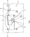
- eine stark schematisierte Seitenansicht eines Zugfahrzeugs eines Sattelzugs mit einem erfindungsgemäßen Fahrerassistenzsystem beim Ankuppelvorgang,
- Fig. 2
- eine Draufsicht auf eine Kupplungsplatte des Zugfahrzeugs,
- Fig. 3
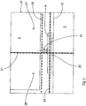
- ein Videobild einer Videokamera des Systems mit eingeblendetem "Zielkreuz" und visualisierter Unterkante eines Aufliegers mit einem Königszapfen,
- Fig. 4
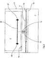
- ein Videobild mit eingeblendeten virtuellen Formen und den von der Videokamera erfassten realen Formen,
- Fig. 5
- eine alternative angepasste Form einer vertikalen Leitlinie,
- Fig. 6
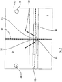
- ein Leitmarkierungssystem mit einem Leitkegel vor einer Ankupplung,
- Fig. 7
- eine Darstellung entsprechend
Fig. 6 nach erfolgter Ankupplung, und - Fig. 8
- eine Darstellung mit einem Verschiebungsvektor aufgrund einer von einer optimalen Kameraposition abweichenden Position.
- Fig. 1
- a highly schematic side view of a towing vehicle of a tractor-trailer with a driver assistance system according to the invention during the coupling process,
- Fig. 2
- a top view of a coupling plate of the towing vehicle,
- Fig. 3
- a video image of a video camera of the system with the "target cross" displayed and the visualized lower edge of a trailer with a kingpin,
- Fig. 4
- a video image with visualized virtual shapes and the real forms captured by the video camera,
- Fig. 5
- an alternative adapted form of a vertical guideline,
- Fig. 6
- a guidance system with a traffic cone before a coupling,
- Fig. 7
- a representation accordingly
Fig. 6 after coupling, and - Fig. 8
- a representation with a displacement vector due to a position deviating from an optimal camera position.
In
Am Zugfahrzeug 2 ist in an sich bekannter Weise eine Kupplungsplatte 4 angeordnet, wie sie in einer Draufsicht mit weiteren Details in
Die Kupplungsplatte 4 weist insbesondere einen nach hinten offenen Einfahrschlitz 5 auf, welcher sich zu einem verriegelbaren Kupplungsschloss 6 hin verengt. Funktionselemente des Verriegelungsschlosses 6 sind eine Zugfeder 7, ein Sicherungshebel 8, ein Handhebel 9, ein Kupplungshaken 10 und ein Verschlusskeil 11 als Verriegelungsklinke.On
The
Der in
Dieses weist u.a. eine Videokamera 14 und einen zugeordneten Bildschirm 15 im Sichtbereich eines Fahrers auf, auf dem das erfasste Videobild gezeigt wird. Die Videokamera 14 ist in Fahrtrichtung vor der Kupplungsplatte 4 an einer Schiene 16 an einer Fahrerhausrückwand 33 angebracht und dabei so ausgerichtet, dass ihre optische Achse 45 (Sichtstrahl) in der Fahrzeuglängsmitte horizontal auf der Höhe der Oberkante der Sattelplatte 4 bzw. des Verriegelungsschlosses 6 verläuft.The in
This has inter alia a
In
Wie aus
Für eine genaue Anpeilung und Anpassung der Position des Zugfahrzeugs 2 bzw. der Kupplungsplatte 4 bei einem Ankuppelvorgang ist in das Videobild 17 ein "Zielkreuz" 20 eingeblendet bestehend aus einer vertikalen Leitlinie 21 durch die Längsmitte des (für einen Fahrer praktisch nicht einsehbaren) Einfahrschlitzes 5 der Kupplungsplatte 4 sowie aus einer horizontalen Höhenlinie 22, welche die Höhe der Oberseite der horizontal ausgerichteten Kupplungsplatte 4 im Kupplungspunkt bzw. in der Mitte des Verriegelungsschlosses 6 visualisiert. Die Kupplungsplatte 4 ist hier in gewissen Grenzen um die y-Achse drehbar gelagert und in einer gekippten Position dargestellt, so dass bei einer Betrachtung des Videobildes (ohne eingeblendeter Höhenlinie 22) die exakte Höhe der Oberseite der Kupplungsplatte 4 im Kupplungspunkt nicht exakt eingesehen bzw. eingeschätzt werden kann. Die eingeblendete horizontale Höhenlinie 22 hilft dem Fahrer bei einer geeigneten Einschätzung insbesondere bei gekippter Kupplungsplatte 4.For a precise bearing and adaptation of the position of towing
Sobald sich der Fahrer mit der Kupplungsplatte 4 dem Auflieger 3 nähert bzw. mit der Kupplungsplatte 4 unter der Aufliegerplatte 24 einfährt, ergibt sich ein Höhenspalt, den der Fahrer mit Hilfe einer pneumatischen Einrichtung zur Anhebung/Absenkung des Zugfahrzeugs ausgleichen muss, so dass die Kupplungsplatte 4 bündig mit der Aufliegerplatte 24 ist. Für diesen Ausgleichsprozess kann der Fahrer die horizontale Höhenlinie 22 heranziehen. Aufgabe des Fahrers ist es dann nur noch, seine pneumatische Einrichtung zur Anhebung/Absenkung des Zugfahrzeugs so zu betätigen, dass die Unterkante 19 des Aufliegers 3 mit der horizontalen Höhenlinie 22 in Deckung gebracht wird bzw. sich auf einem definierten Abstand nähert.As soon as the driver approaches the
Optional kann die Erfassung der vorderen Unterkante 19 des Aufliegers 3 oder sonstiger Bauteile, welche eine Höheneinschätzung erlauben automatisch mit Hilfe von Bildverarbeitungsalgorithmen erfolgen. Weiterhin kann optional der Höhenausgleich insgesamt auch automatisch erfolgen.Optionally, the detection of the front
In
Weiter ist in
Ähnlich können auch weitere Leitlinien eingeblendet werden, welche bei definierten Abständen zwischen Zugfahrzeug 2 und Auflieger 3 mit definierten Kanten des sich nähernden Aufliegers 3 übereinstimmen. Derartige Kanten können beispielsweise die vier vorderen Außenkanten des Aufliegers sein. Die Einblendung dieser virtuellen Markierungen kann selbsttätig oder gegebenenfalls durch den Fahrer manuell erfolgen.Similarly, other guidelines can be displayed, which coincide with defined distances between towing
Mit
Wenn die Position und Ausrichtung der Videokamera 14 von der in Verbindung mit den
Ersichtlich weist der Leitkegel 31 einen abgeflachten "Kegelboden" 32 auf, wobei dessen Breite dem seitlichen Toleranzbereich der Einkuppelstelle entspricht.Visible, the
Wenn die Kameraposition gegenüber der optimalen Position in Richtung der z-Achse und der y-Achse verschoben ist, so ist die Symmetrieachse des Leitkegels 31 entsprechend dem Winkel α eines Verschiebungsvektors auszurichten, wie dies schematisch in
In ![]()
![]()
Die Symmetrieachse eines hier relevanten Leitkegels 31 ist entsprechend dem Winkel α des Verschiebungsvektors 36 auszurichten.The axis of symmetry of a relevant here
- 11
- SattelzugTractor
- 22
- Zugfahrzeugtowing vehicle
- 33
- Aufliegersemitrailer
- 44
- Kupplungsplatteclutch plate
- 55
- EinfahrschlitzEinfahrschlitz
- 66
- Verriegelungsschlosslock lock
- 77
- Zugfedermainspring
- 88th
- Sicherungshebelsafety lever
- 99
- Handhebelhand lever
- 1010
- Kupplungshakencoupling hook
- 1111
- Verschlusskeilcover wedge
- 1212
- Stützesupport
- 1313
- Königszapfenkingpin
- 1414
- Videokameravideo camera
- 1515
- Bildschirmscreen
- 1616
- Schienerail
- 1717
- Videobildvideo image
- 1818
- Oberkantetop edge
- 1919
- vordere Unterkantefront lower edge
- 2020
- Zielkreuzcrosshair
- 2121
- vertikale Leitlinievertical guideline
- 2222
- horizontale Höhenliniehorizontal contour line
- 2323
- virtuelle Formvirtual shape
- 2424
- Aufliegerplatteskid plate
- 2525
- horizontale Markierungsliniehorizontal marking line
- 2626
- Markierungspunktmarker
- 2727
- Markierungspunktmarker
- 2828
- Rechteckrectangle
- 2929
- Rechteckbreiterectangle width
- 3030
- Rechteckhöherectangle height
- 3131
- Leitkegeltraffic cone
- 3232
- Kegelbodenconical
- 3333
- FahrerhausrückwandCab rear wall
- 3434
- optimale Kamerapositionoptimal camera position
- 3535
- abweichende Kamerapositiondifferent camera position
- 3636
- Pfeilarrow
- 4545
- optische Achseoptical axis
- ΔzAz
- Distanzdistance
- ΔyDy
- Distanzdistance
- αα
- Winkelcorner
Claims (16)
- Driver assistance system for a commercial vehicle trailer combination, wherein the commercial vehicle trailer combination is constructed as a tractor/semitrailer combination (1) comprising a traction vehicle (2) and a semitrailer (3), wherein a coupling apparatus is provided, which coupling apparatus has a traction vehicle-side, lockable coupling receiving part (4; 37) and an associated coupling element (13; 44), which can be inserted into the coupling receiving part (4; 37), on the semitrailer (3), and wherein a reversing camera device comprising a video camera (14) and comprising an associated screen (15) for a video image (17) in the field of view of a driver is provided on the traction vehicle side, wherein a guide marking, which is visible to the driver, is superimposed into the video image (17) as an aiming aid, which guide marking visualises the insertion region for the coupling element (13; 44) on the coupling receiving part (4; 37),
characterized in that the video camera (14) is associated with the coupling receiving part (4; 37) such that the region of the coupling receiving part (4; 37) and a rear surrounding area containing the coupling element (13; 44) can be recorded and can be depicted in the video image (17). - Driver assistance system according to Claim 1, characterized in that the guide marking in the video image (17) has or is a vertical guide line (21) which runs through an insertion slot (5) of a coupling plate (4) of the traction vehicle (2) of the tractor/semitrailer combination (1), which insertion slot is open to the rear in the direction of the vehicle longitudinal axis, in particular for exact horizontal aiming of the tractor/semitrailer combination kingpin (13) on the semitrailer plate (24) of a semitrailer (3).
- Driver assistance system according to Claim 2, characterized in that the guide marking in the video image (17) is designed in the form of a target cross (20) which is formed from the vertical guide line (21) and a horizontal auxiliary elevation line (22) which visualises an elevation on the traction vehicle (2), which elevation is relevant for the coupling process.
- Driver assistance system according to Claim 3, characterized in that the horizontal auxiliary elevation line visualises, in the traction vehicle (2) of the tractor/semitrailer combination (1), the elevation of the top side of a coupling plate (4), preferably a coupling plate (4) which can be tilted about a vehicle transverse axis (y axis), at the coupling point and/or the middle of a coupling lock (6) of a coupling plate (4), in particular for assisting the driver with vertical elevation adjustment between the coupling plate (4) and the semitrailer plate (24) during the coupling-on process, or in that the horizontal auxiliary elevation line (22) visualises, in the traction vehicle of a truck/trailer combination, the elevation of a jaw (38) of an open-end coupling (37).
- Driver assistance system according to Claim 3 or 4, characterized in that an image processing device, in particular an image processing device with at least one image processing algorithm, is provided, by means of which image processing device a bottom edge (19) of the semitrailer (3) of the tractor/semitrailer combination (1), which bottom edge is at the front in the direction of travel, and/or that of defined components of the semitrailer (3) of the tractor/semitrailer combination (1) which, during the coupling-on process, allow elevation estimation of the relative position between the coupling plate (4) and the semitrailer plate (24) and/or a fifth-wheel kingpin (13), can be recorded, in particular can be automatically recorded.
- Driver assistance system according to one of the preceding claims, characterized in that a device for raising/lowering the traction vehicle (2) and/or the semitrailer (3) is provided, by means of which device elevation compensation can be carried out, in particular can be carried out automatically, during the coupling-on process by evaluating image data relating to the relative position between the coupling receiving part (4; 37) and the coupling element (13; 44).
- Driver assistance system according to one of the preceding claims, characterized in that a device for determining and/or estimating the horizontal distance as the coupling receiving part (4; 38) and the coupling element (13; 44) approach each other, in particular as a coupling plate (4) and a fifth-wheel kingpin (13) of the tractor/semitrailer combination (1) approach each other, is provided, by means of which device at least one auxiliary marking, which illustrates the distance, can be superimposed into the video image as an element of a guide marking or a virtual shape which forms an element of a guide marking.
- Driver assistance system according to Claim 7, characterized in that the at least one auxiliary marking is a distance determining aid comprising at least one guide line (25) which is superimposed into the video image and which, given defined distances between the traction vehicle (2) and the semitrailer (3), corresponds to at least one defined edge, in particular to at least one associated outer edge, of the semitrailer (3), and/or in that the at least one auxiliary marking is formed by at least one superimposed virtual shape (23) which, given a defined distance between the traction vehicle (2) and the semitrailer (3), corresponds to at least one defined component (13; 26, 27) of the semitrailer (3) and/or the shape thereof in respect of size.
- Driver assistance system according to Claim 7 or Claim 8, characterized in that, using the device for determining and/or estimating the horizontal distance, at least one standardized component (13) of the semitrailer (3), which component is depicted in the video image (17), can be recorded by means of an image processing device and the size recorded at that instant can be compared with the known, stored real size, wherein provision is preferably made for the real distance to be determined from the size comparison at that instant by means of an evaluation device and to be graphically and/or numerically displayed to the driver.
- Driver assistance system according to one of the preceding claims, characterized in that an adjustment device is provided, by means of which at least some of the elements which form the guide marking, in particular guide lines (21, 22) and/or auxiliary markings (23) and/or a target cross (20), can be automatically or manually adjusted in respect of colour and/or in respect of transparency and/or in respect of shape (28) to match the visualization conditions and/or tolerance ranges and/or physically possible regions in a stationary or dynamic manner depending on the progress during the coupling-on process.
- Driver assistance system according to one of the preceding claims, characterized in that a zoom device is provided, by means of which the image detail displayed in the or as the video image can be manually or automatically changed in respect of size, in particular depending on the coupling-on process.
- Driver assistance system according to one of the preceding claims, characterized in that the video camera (14) is positioned on the traction vehicle (2) of the tractor/semitrailer combination (1) such that the optical axis (45) thereof in the longitudinal centre of the vehicle runs horizontally level with the top edge of the coupling plate (4), or in that the video camera (14) on the traction vehicle (2) of a truck/trailer combination is aligned with an optical axis in the longitudinal centre of the vehicle.
- Driver assistance system according to one of the preceding claims, characterized in that the video camera (14) is positioned on the traction vehicle (2) of the tractor/semitrailer combination (1) such that the position thereof in the y and/or z direction deviates from a horizontal optical axis (45) through the longitudinal centre of the vehicle level with the top edge of the coupling receiving part (4), and in that, in this case, a guide cone (31) is further superimposed in addition to a target cross (20) comprising a vertical guide line (21) and horizontal elevation line (22) as guide marking, the guide cone opening and cone axis of said guide cone being oriented in the direction of the deviation, wherein the guide cone (31) may be flattened in the region of the target cross (20) with a cone base (32) and the width of the cone base (32) corresponds to the lateral tolerance range of the coupling-in point in this case.
- Driver assistance system according to Claim 13, characterized in that the video camera (14) is fastened to the rear wall (33) of the driver compartment cabin or fixed to the frame of the vehicle, in particular on a rail (16) there which runs in the z direction.
- Method for carrying out a coupling-on process for a commercial vehicle trailer combination comprising a driver assistance system, wherein the commercial vehicle trailer combination is constructed as a tractor/semitrailer combination (1) comprising a traction vehicle (2) and a semitrailer (3), wherein a coupling apparatus is provided, which coupling apparatus has a traction vehicle-side, lockable coupling receiving part (4; 37) and an associated coupling element (13; 44), which can be inserted into the coupling receiving part (4; 37), on the semitrailer (3), and wherein a reversing camera device comprising a video camera (14) and comprising an associated screen (15) for a video image (17) in the field of view of a driver is provided on the traction vehicle side, characterized in that the video camera (14) is associated with the coupling receiving part (4; 37) such that the said video camera records the region of the coupling receiving part (4; 37) and a rear surrounding area containing the coupling element (13; 44) and depicts them in the video image (17), and in that at least one guide marking, which is visible to the driver, is superimposed into the video image (17) as the aiming aid, which aiming aid visualises the insertion region for the coupling element (13; 44) on the coupling receiving part (4; 37).
- Commercial vehicle comprising a driver assistance system according to one of the preceding Claims 1 to 14 for carrying out a method according to Claim 15.
Applications Claiming Priority (1)
| Application Number | Priority Date | Filing Date | Title |
|---|---|---|---|
| DE102014012330.8A DE102014012330A1 (en) | 2014-08-20 | 2014-08-20 | Driver assistance system for a commercial vehicle combination and method for carrying out a coupling process |
Publications (2)
| Publication Number | Publication Date |
|---|---|
| EP2987663A1 EP2987663A1 (en) | 2016-02-24 |
| EP2987663B1 true EP2987663B1 (en) | 2019-05-08 |
Family
ID=52814774
Family Applications (1)
| Application Number | Title | Priority Date | Filing Date |
|---|---|---|---|
| EP15000914.0A Active EP2987663B1 (en) | 2014-08-20 | 2015-03-28 | Driver assistance system for a commercial vehicle trailer assembly and method for performing a coupling procedure |
Country Status (2)
| Country | Link |
|---|---|
| EP (1) | EP2987663B1 (en) |
| DE (1) | DE102014012330A1 (en) |
Families Citing this family (13)
| Publication number | Priority date | Publication date | Assignee | Title |
|---|---|---|---|---|
| DE102016011324A1 (en) | 2016-09-21 | 2018-03-22 | Wabco Gmbh | A method of controlling a towing vehicle as it approaches and hitches to a trailer vehicle |
| JP6909862B2 (en) * | 2017-03-06 | 2021-07-28 | ボルボトラックコーポレーション | How to support automatic trailer disconnection / connection |
| DE102017119969B4 (en) * | 2017-08-31 | 2023-01-05 | Saf-Holland Gmbh | Trailer with a trailer controller, hitch system and method for performing a hitch process |
| DE102017119968B4 (en) | 2017-08-31 | 2020-06-18 | Saf-Holland Gmbh | Trailer and system for identifying a trailer and supporting a coupling process to a tractor |
| DE102017221458B3 (en) | 2017-11-29 | 2019-02-07 | Volkswagen Aktiengesellschaft | Method for operating an operating device for a motor vehicle to assist a driver when coupling the motor vehicle to a trailer, and operating device and motor vehicle |
| DE102018204442B4 (en) * | 2018-03-22 | 2021-05-27 | Zf Friedrichshafen Ag | Trailer and method and control device for determining an orientation of a trailer |
| DE102018210356A1 (en) * | 2018-06-26 | 2020-01-02 | Zf Friedrichshafen Ag | Method for assisting a driver of a commercial vehicle when driving under a swap body and driver assistance system |
| DE102018210361B4 (en) * | 2018-06-26 | 2020-07-23 | Zf Friedrichshafen Ag | Method for determining a relative pose between a vehicle and a target object |
| DE102018214973A1 (en) * | 2018-09-04 | 2020-03-05 | Volkswagen Aktiengesellschaft | Method and system for automatically recognizing a coupling maneuver of a motor vehicle to a trailer |
| DE102020003141A1 (en) | 2020-05-26 | 2021-12-02 | Jost-Werke Deutschland Gmbh | Driver assistance system and method for coupling a trailer to a towing vehicle |
| CN114425930A (en) * | 2022-02-24 | 2022-05-03 | 一汽解放汽车有限公司 | Trailer auxiliary device |
| DE102022003318A1 (en) | 2022-09-09 | 2024-03-14 | Jost-Werke Deutschland Gmbh | ALIGNMENT SYSTEM FOR APPROACHING A VEHICLE TO A SPATIALLY DISTANCED TARGET OBJECT |
| DE102022123359A1 (en) | 2022-09-13 | 2024-03-14 | Jost-Werke Deutschland Gmbh | Method for coupling a tractor unit with a semi-trailer and a tractor unit with a tractor unit and a semi-trailer |
Citations (2)
| Publication number | Priority date | Publication date | Assignee | Title |
|---|---|---|---|---|
| DE102004043761A1 (en) * | 2004-09-10 | 2006-03-16 | Daimlerchrysler Ag | Tow coupling monitoring method for towing vehicle, involves comparing graphic data with allowed samples and threshold values for producing assistance signals, and displaying data and signals for monitoring coupling process of coupling |
| EP2921350A2 (en) * | 2014-03-20 | 2015-09-23 | MAN Truck & Bus AG | Camera-based driver assistance system for a traction vehicle, in particular of a traction vehicle of a combination of commercial vehicles |
Family Cites Families (3)
| Publication number | Priority date | Publication date | Assignee | Title |
|---|---|---|---|---|
| DE102004029129B4 (en) * | 2004-06-17 | 2008-08-28 | Daimler Ag | Method and device for coupling a trailer to a motor vehicle |
| DE102004029130A1 (en) * | 2004-06-17 | 2005-12-29 | Daimlerchrysler Ag | Method for coupling a trailer to a motor vehicle |
| US20140151979A1 (en) * | 2012-12-03 | 2014-06-05 | Fontaine Fifth Wheel | Fifth Wheel Backup Camera System and Method |
-
2014
- 2014-08-20 DE DE102014012330.8A patent/DE102014012330A1/en not_active Withdrawn
-
2015
- 2015-03-28 EP EP15000914.0A patent/EP2987663B1/en active Active
Patent Citations (2)
| Publication number | Priority date | Publication date | Assignee | Title |
|---|---|---|---|---|
| DE102004043761A1 (en) * | 2004-09-10 | 2006-03-16 | Daimlerchrysler Ag | Tow coupling monitoring method for towing vehicle, involves comparing graphic data with allowed samples and threshold values for producing assistance signals, and displaying data and signals for monitoring coupling process of coupling |
| EP2921350A2 (en) * | 2014-03-20 | 2015-09-23 | MAN Truck & Bus AG | Camera-based driver assistance system for a traction vehicle, in particular of a traction vehicle of a combination of commercial vehicles |
Also Published As
| Publication number | Publication date |
|---|---|
| EP2987663A1 (en) | 2016-02-24 |
| DE102014012330A1 (en) | 2016-02-25 |
Similar Documents
| Publication | Publication Date | Title |
|---|---|---|
| EP2987663B1 (en) | Driver assistance system for a commercial vehicle trailer assembly and method for performing a coupling procedure | |
| DE112012000466B4 (en) | System and method for maneuvering a vehicle-trailer combination when reversing | |
| EP3024700B1 (en) | Method and device for reproducing a lateral and/or rear surrounding area of a vehicle | |
| EP3219533B1 (en) | Viewing system for a motor vehicle, in particular a commercial vehicle | |
| EP3560796B1 (en) | Trailer driving assistance system for a motor vehicle and method for operating a trailer driving assistance system of a motor vehicle | |
| DE10109350B4 (en) | Assistance device for reverse parking a vehicle in series | |
| EP3012154B1 (en) | Method and device to support a driver of a vehicle combination, in particular a commercial vehicle combination | |
| DE102007011180A1 (en) | Rangierhilfe and method for drivers of vehicles or vehicle combinations, which consist of mutually bendable vehicle elements | |
| DE102014204872B4 (en) | A method and display system for displaying environmental information of a vehicle | |
| DE102019117132A1 (en) | SYSTEM AND METHOD FOR DETECTING AND RESPONDING TO FAILURE BETWEEN TRAILER CONNECTOR AND TRAILER JOINT BALL | |
| DE102009032024A1 (en) | A method for determining a position of a trailer attached to a vehicle relative to the vehicle and driver assistance system for a vehicle | |
| WO2019145161A1 (en) | Video monitoring system and method and device for operating a video monitoring system for a motor vehicle | |
| DE102016109954A1 (en) | A method for assisting a driver of a team when maneuvering the team, driver assistance system and motor vehicle | |
| DE102020127261A1 (en) | ALIGNMENT POSITION ADJUSTMENT FOR ATTACHMENT HITCH TRAILERS IN HITCH SUPPORT OPERATION | |
| EP2949532A2 (en) | Method and driver assistance system for assisting a driver of a commercial vehicle | |
| EP3284649A1 (en) | Driver assistance for parking a motor vehicle and a trailer by means of virtual sensors | |
| DE102020107023A1 (en) | TRAILER ALIGNMENT SYSTEM AND PROCEDURE | |
| DE112019001414T5 (en) | CONTROL UNIT FOR A VEHICLE | |
| DE102014218995A1 (en) | Method and device for bird-view display of a vehicle combination and retrofittable camera | |
| EP3476696B1 (en) | Method for determining object boundaries of an object in an external area of a motor vehicle and control device and motor vehicle | |
| WO2021160637A1 (en) | Method and system for ascertaining an orientation of a trailer relative to a tractor vehicle | |
| DE102016117401B4 (en) | Method and device for imaging a trailer with boundary markings | |
| EP3915838B1 (en) | Driver assistance system and method for coupling a trailer onto a tractor | |
| DE102016110305B4 (en) | Method for supporting a driver of a motor vehicle when maneuvering the motor vehicle with a trailer, driver assistance system and motor vehicle | |
| EP4344908A2 (en) | Alignment system for approaching a vehicle to a target object spatially spaced apart from said system |
Legal Events
| Date | Code | Title | Description |
|---|---|---|---|
| PUAI | Public reference made under article 153(3) epc to a published international application that has entered the european phase |
Free format text: ORIGINAL CODE: 0009012 |
|
| AK | Designated contracting states |
Kind code of ref document: A1 Designated state(s): AL AT BE BG CH CY CZ DE DK EE ES FI FR GB GR HR HU IE IS IT LI LT LU LV MC MK MT NL NO PL PT RO RS SE SI SK SM TR |
|
| AX | Request for extension of the european patent |
Extension state: BA ME |
|
| 17P | Request for examination filed |
Effective date: 20160822 |
|
| STAA | Information on the status of an ep patent application or granted ep patent |
Free format text: STATUS: EXAMINATION IS IN PROGRESS |
|
| 17Q | First examination report despatched |
Effective date: 20180130 |
|
| GRAP | Despatch of communication of intention to grant a patent |
Free format text: ORIGINAL CODE: EPIDOSNIGR1 |
|
| STAA | Information on the status of an ep patent application or granted ep patent |
Free format text: STATUS: GRANT OF PATENT IS INTENDED |
|
| INTG | Intention to grant announced |
Effective date: 20181105 |
|
| GRAS | Grant fee paid |
Free format text: ORIGINAL CODE: EPIDOSNIGR3 |
|
| GRAA | (expected) grant |
Free format text: ORIGINAL CODE: 0009210 |
|
| STAA | Information on the status of an ep patent application or granted ep patent |
Free format text: STATUS: THE PATENT HAS BEEN GRANTED |
|
| AK | Designated contracting states |
Kind code of ref document: B1 Designated state(s): AL AT BE BG CH CY CZ DE DK EE ES FI FR GB GR HR HU IE IS IT LI LT LU LV MC MK MT NL NO PL PT RO RS SE SI SK SM TR |
|
| REG | Reference to a national code |
Ref country code: GB Ref legal event code: FG4D Free format text: NOT ENGLISH |
|
| REG | Reference to a national code |
Ref country code: CH Ref legal event code: EP Ref country code: AT Ref legal event code: REF Ref document number: 1129577 Country of ref document: AT Kind code of ref document: T Effective date: 20190515 |
|
| REG | Reference to a national code |
Ref country code: DE Ref legal event code: R096 Ref document number: 502015008938 Country of ref document: DE |
|
| REG | Reference to a national code |
Ref country code: IE Ref legal event code: FG4D Free format text: LANGUAGE OF EP DOCUMENT: GERMAN |
|
| REG | Reference to a national code |
Ref country code: NL Ref legal event code: FP |
|
| RAP2 | Party data changed (patent owner data changed or rights of a patent transferred) |
Owner name: MAN TRUCK & BUS SE |
|
| REG | Reference to a national code |
Ref country code: SE Ref legal event code: TRGR |
|
| REG | Reference to a national code |
Ref country code: LT Ref legal event code: MG4D Ref country code: DE Ref legal event code: R081 Ref document number: 502015008938 Country of ref document: DE Owner name: MAN TRUCK & BUS SE, DE Free format text: FORMER OWNER: MAN TRUCK & BUS AG, 80995 MUENCHEN, DE |
|
| PG25 | Lapsed in a contracting state [announced via postgrant information from national office to epo] |
Ref country code: AL Free format text: LAPSE BECAUSE OF FAILURE TO SUBMIT A TRANSLATION OF THE DESCRIPTION OR TO PAY THE FEE WITHIN THE PRESCRIBED TIME-LIMIT Effective date: 20190508 Ref country code: ES Free format text: LAPSE BECAUSE OF FAILURE TO SUBMIT A TRANSLATION OF THE DESCRIPTION OR TO PAY THE FEE WITHIN THE PRESCRIBED TIME-LIMIT Effective date: 20190508 Ref country code: LT Free format text: LAPSE BECAUSE OF FAILURE TO SUBMIT A TRANSLATION OF THE DESCRIPTION OR TO PAY THE FEE WITHIN THE PRESCRIBED TIME-LIMIT Effective date: 20190508 Ref country code: FI Free format text: LAPSE BECAUSE OF FAILURE TO SUBMIT A TRANSLATION OF THE DESCRIPTION OR TO PAY THE FEE WITHIN THE PRESCRIBED TIME-LIMIT Effective date: 20190508 Ref country code: PT Free format text: LAPSE BECAUSE OF FAILURE TO SUBMIT A TRANSLATION OF THE DESCRIPTION OR TO PAY THE FEE WITHIN THE PRESCRIBED TIME-LIMIT Effective date: 20190908 Ref country code: NO Free format text: LAPSE BECAUSE OF FAILURE TO SUBMIT A TRANSLATION OF THE DESCRIPTION OR TO PAY THE FEE WITHIN THE PRESCRIBED TIME-LIMIT Effective date: 20190808 Ref country code: HR Free format text: LAPSE BECAUSE OF FAILURE TO SUBMIT A TRANSLATION OF THE DESCRIPTION OR TO PAY THE FEE WITHIN THE PRESCRIBED TIME-LIMIT Effective date: 20190508 |
|
| PG25 | Lapsed in a contracting state [announced via postgrant information from national office to epo] |
Ref country code: LV Free format text: LAPSE BECAUSE OF FAILURE TO SUBMIT A TRANSLATION OF THE DESCRIPTION OR TO PAY THE FEE WITHIN THE PRESCRIBED TIME-LIMIT Effective date: 20190508 Ref country code: GR Free format text: LAPSE BECAUSE OF FAILURE TO SUBMIT A TRANSLATION OF THE DESCRIPTION OR TO PAY THE FEE WITHIN THE PRESCRIBED TIME-LIMIT Effective date: 20190809 Ref country code: BG Free format text: LAPSE BECAUSE OF FAILURE TO SUBMIT A TRANSLATION OF THE DESCRIPTION OR TO PAY THE FEE WITHIN THE PRESCRIBED TIME-LIMIT Effective date: 20190808 Ref country code: RS Free format text: LAPSE BECAUSE OF FAILURE TO SUBMIT A TRANSLATION OF THE DESCRIPTION OR TO PAY THE FEE WITHIN THE PRESCRIBED TIME-LIMIT Effective date: 20190508 |
|
| PG25 | Lapsed in a contracting state [announced via postgrant information from national office to epo] |
Ref country code: RO Free format text: LAPSE BECAUSE OF FAILURE TO SUBMIT A TRANSLATION OF THE DESCRIPTION OR TO PAY THE FEE WITHIN THE PRESCRIBED TIME-LIMIT Effective date: 20190508 Ref country code: CZ Free format text: LAPSE BECAUSE OF FAILURE TO SUBMIT A TRANSLATION OF THE DESCRIPTION OR TO PAY THE FEE WITHIN THE PRESCRIBED TIME-LIMIT Effective date: 20190508 Ref country code: EE Free format text: LAPSE BECAUSE OF FAILURE TO SUBMIT A TRANSLATION OF THE DESCRIPTION OR TO PAY THE FEE WITHIN THE PRESCRIBED TIME-LIMIT Effective date: 20190508 Ref country code: DK Free format text: LAPSE BECAUSE OF FAILURE TO SUBMIT A TRANSLATION OF THE DESCRIPTION OR TO PAY THE FEE WITHIN THE PRESCRIBED TIME-LIMIT Effective date: 20190508 Ref country code: SK Free format text: LAPSE BECAUSE OF FAILURE TO SUBMIT A TRANSLATION OF THE DESCRIPTION OR TO PAY THE FEE WITHIN THE PRESCRIBED TIME-LIMIT Effective date: 20190508 |
|
| REG | Reference to a national code |
Ref country code: DE Ref legal event code: R097 Ref document number: 502015008938 Country of ref document: DE |
|
| PG25 | Lapsed in a contracting state [announced via postgrant information from national office to epo] |
Ref country code: SM Free format text: LAPSE BECAUSE OF FAILURE TO SUBMIT A TRANSLATION OF THE DESCRIPTION OR TO PAY THE FEE WITHIN THE PRESCRIBED TIME-LIMIT Effective date: 20190508 |
|
| PLBE | No opposition filed within time limit |
Free format text: ORIGINAL CODE: 0009261 |
|
| STAA | Information on the status of an ep patent application or granted ep patent |
Free format text: STATUS: NO OPPOSITION FILED WITHIN TIME LIMIT |
|
| PG25 | Lapsed in a contracting state [announced via postgrant information from national office to epo] |
Ref country code: TR Free format text: LAPSE BECAUSE OF FAILURE TO SUBMIT A TRANSLATION OF THE DESCRIPTION OR TO PAY THE FEE WITHIN THE PRESCRIBED TIME-LIMIT Effective date: 20190508 |
|
| 26N | No opposition filed |
Effective date: 20200211 |
|
| PG25 | Lapsed in a contracting state [announced via postgrant information from national office to epo] |
Ref country code: PL Free format text: LAPSE BECAUSE OF FAILURE TO SUBMIT A TRANSLATION OF THE DESCRIPTION OR TO PAY THE FEE WITHIN THE PRESCRIBED TIME-LIMIT Effective date: 20190508 |
|
| PG25 | Lapsed in a contracting state [announced via postgrant information from national office to epo] |
Ref country code: SI Free format text: LAPSE BECAUSE OF FAILURE TO SUBMIT A TRANSLATION OF THE DESCRIPTION OR TO PAY THE FEE WITHIN THE PRESCRIBED TIME-LIMIT Effective date: 20190508 |
|
| PG25 | Lapsed in a contracting state [announced via postgrant information from national office to epo] |
Ref country code: MC Free format text: LAPSE BECAUSE OF FAILURE TO SUBMIT A TRANSLATION OF THE DESCRIPTION OR TO PAY THE FEE WITHIN THE PRESCRIBED TIME-LIMIT Effective date: 20190508 |
|
| REG | Reference to a national code |
Ref country code: CH Ref legal event code: PL |
|
| REG | Reference to a national code |
Ref country code: BE Ref legal event code: MM Effective date: 20200331 |
|
| PG25 | Lapsed in a contracting state [announced via postgrant information from national office to epo] |
Ref country code: LU Free format text: LAPSE BECAUSE OF NON-PAYMENT OF DUE FEES Effective date: 20200328 |
|
| PG25 | Lapsed in a contracting state [announced via postgrant information from national office to epo] |
Ref country code: IE Free format text: LAPSE BECAUSE OF NON-PAYMENT OF DUE FEES Effective date: 20200328 Ref country code: LI Free format text: LAPSE BECAUSE OF NON-PAYMENT OF DUE FEES Effective date: 20200331 Ref country code: CH Free format text: LAPSE BECAUSE OF NON-PAYMENT OF DUE FEES Effective date: 20200331 |
|
| PG25 | Lapsed in a contracting state [announced via postgrant information from national office to epo] |
Ref country code: BE Free format text: LAPSE BECAUSE OF NON-PAYMENT OF DUE FEES Effective date: 20200331 |
|
| GBPC | Gb: european patent ceased through non-payment of renewal fee |
Effective date: 20200328 |
|
| PG25 | Lapsed in a contracting state [announced via postgrant information from national office to epo] |
Ref country code: GB Free format text: LAPSE BECAUSE OF NON-PAYMENT OF DUE FEES Effective date: 20200328 |
|
| REG | Reference to a national code |
Ref country code: AT Ref legal event code: MM01 Ref document number: 1129577 Country of ref document: AT Kind code of ref document: T Effective date: 20200328 |
|
| PG25 | Lapsed in a contracting state [announced via postgrant information from national office to epo] |
Ref country code: AT Free format text: LAPSE BECAUSE OF NON-PAYMENT OF DUE FEES Effective date: 20200328 |
|
| PG25 | Lapsed in a contracting state [announced via postgrant information from national office to epo] |
Ref country code: MT Free format text: LAPSE BECAUSE OF FAILURE TO SUBMIT A TRANSLATION OF THE DESCRIPTION OR TO PAY THE FEE WITHIN THE PRESCRIBED TIME-LIMIT Effective date: 20190508 Ref country code: CY Free format text: LAPSE BECAUSE OF FAILURE TO SUBMIT A TRANSLATION OF THE DESCRIPTION OR TO PAY THE FEE WITHIN THE PRESCRIBED TIME-LIMIT Effective date: 20190508 |
|
| PG25 | Lapsed in a contracting state [announced via postgrant information from national office to epo] |
Ref country code: MK Free format text: LAPSE BECAUSE OF FAILURE TO SUBMIT A TRANSLATION OF THE DESCRIPTION OR TO PAY THE FEE WITHIN THE PRESCRIBED TIME-LIMIT Effective date: 20190508 Ref country code: IS Free format text: LAPSE BECAUSE OF FAILURE TO SUBMIT A TRANSLATION OF THE DESCRIPTION OR TO PAY THE FEE WITHIN THE PRESCRIBED TIME-LIMIT Effective date: 20190908 |
|
| PGFP | Annual fee paid to national office [announced via postgrant information from national office to epo] |
Ref country code: FR Payment date: 20230323 Year of fee payment: 9 |
|
| PGFP | Annual fee paid to national office [announced via postgrant information from national office to epo] |
Ref country code: SE Payment date: 20230317 Year of fee payment: 9 Ref country code: IT Payment date: 20230321 Year of fee payment: 9 Ref country code: DE Payment date: 20230328 Year of fee payment: 9 |
|
| PGFP | Annual fee paid to national office [announced via postgrant information from national office to epo] |
Ref country code: NL Payment date: 20240326 Year of fee payment: 10 |
|
| PGFP | Annual fee paid to national office [announced via postgrant information from national office to epo] |
Ref country code: DE Payment date: 20240328 Year of fee payment: 10 |