EP2982243B1 - Device and method for controlling the motion of a distribution rod system of an agricultural distributor - Google Patents
Device and method for controlling the motion of a distribution rod system of an agricultural distributor Download PDFInfo
- Publication number
- EP2982243B1 EP2982243B1 EP15401080.5A EP15401080A EP2982243B1 EP 2982243 B1 EP2982243 B1 EP 2982243B1 EP 15401080 A EP15401080 A EP 15401080A EP 2982243 B1 EP2982243 B1 EP 2982243B1
- Authority
- EP
- European Patent Office
- Prior art keywords
- rod system
- distribution rod
- frame
- distribution
- distributor
- Prior art date
- Legal status (The legal status is an assumption and is not a legal conclusion. Google has not performed a legal analysis and makes no representation as to the accuracy of the status listed.)
- Active
Links
- 230000033001 locomotion Effects 0.000 title claims description 52
- 238000000034 method Methods 0.000 title claims description 35
- 230000001133 acceleration Effects 0.000 claims description 76
- 238000005452 bending Methods 0.000 claims description 25
- 238000013016 damping Methods 0.000 claims description 23
- 239000000725 suspension Substances 0.000 claims description 18
- 239000007921 spray Substances 0.000 claims description 17
- 230000010355 oscillation Effects 0.000 claims description 6
- 230000001105 regulatory effect Effects 0.000 claims description 6
- 230000001276 controlling effect Effects 0.000 claims description 5
- 230000033228 biological regulation Effects 0.000 claims description 4
- 241000238631 Hexapoda Species 0.000 claims description 3
- 230000002265 prevention Effects 0.000 claims description 3
- 230000008569 process Effects 0.000 description 20
- 230000000694 effects Effects 0.000 description 8
- 230000008859 change Effects 0.000 description 7
- 239000006096 absorbing agent Substances 0.000 description 6
- 230000003534 oscillatory effect Effects 0.000 description 5
- 230000008901 benefit Effects 0.000 description 3
- 230000005484 gravity Effects 0.000 description 3
- 230000000052 comparative effect Effects 0.000 description 2
- 239000000203 mixture Substances 0.000 description 2
- 210000003205 muscle Anatomy 0.000 description 2
- 230000009471 action Effects 0.000 description 1
- 238000013459 approach Methods 0.000 description 1
- 239000003795 chemical substances by application Substances 0.000 description 1
- 230000008878 coupling Effects 0.000 description 1
- 238000010168 coupling process Methods 0.000 description 1
- 238000005859 coupling reaction Methods 0.000 description 1
- 230000007423 decrease Effects 0.000 description 1
- 230000003247 decreasing effect Effects 0.000 description 1
- 230000003111 delayed effect Effects 0.000 description 1
- 238000010586 diagram Methods 0.000 description 1
- 238000006073 displacement reaction Methods 0.000 description 1
- 239000007788 liquid Substances 0.000 description 1
- 238000013017 mechanical damping Methods 0.000 description 1
- 230000007246 mechanism Effects 0.000 description 1
- 230000004044 response Effects 0.000 description 1
- 238000005096 rolling process Methods 0.000 description 1
- 230000035939 shock Effects 0.000 description 1
- 230000000638 stimulation Effects 0.000 description 1
- 230000002459 sustained effect Effects 0.000 description 1
Images
Classifications
-
- A—HUMAN NECESSITIES
- A01—AGRICULTURE; FORESTRY; ANIMAL HUSBANDRY; HUNTING; TRAPPING; FISHING
- A01M—CATCHING, TRAPPING OR SCARING OF ANIMALS; APPARATUS FOR THE DESTRUCTION OF NOXIOUS ANIMALS OR NOXIOUS PLANTS
- A01M7/00—Special adaptations or arrangements of liquid-spraying apparatus for purposes covered by this subclass
- A01M7/005—Special arrangements or adaptations of the spraying or distributing parts, e.g. adaptations or mounting of the spray booms, mounting of the nozzles, protection shields
- A01M7/0053—Mounting of the spraybooms
- A01M7/0057—Mounting of the spraybooms with active regulation of the boom position
Definitions
- the present invention relates to an apparatus and a method for motion control of a distribution linkage of an agricultural distribution machine according to the preambles of independent claims 1 and 11.
- Field sprayers this applies to both self-propelled and attached to towing vehicles such as tractors or mounted field sprayers, with their distribution linkage, which serves to distribute the means provided, a very large working width, sometimes over 35 m on.
- the oscillation of the boom of the field sprayer can be prevented or minimized around a vertical axis arranged perpendicular to the direction of travel by the spray boom being oscillatingly attached to the frame and coupled via damping elements to the frame of the field sprayer.
- the above measures are not suitable for preventing a swinging movement in the direction of travel of the field sprayer instead of a rotary movement or pendulum movement of the distributor linkage.
- the opposite sides of the linkage move relative to the center of the linkage at least approximately in-phase or in other words simultaneously in the same direction in and against the direction of travel of the field sprayer.
- causes of such movements as mentioned above, for example, be caused by the start, increase the speed of the working machine or braking accelerations.
- it may also be rolling movements of the sprayer due to unevenness of the ground or a fluctuating liquid level of the spray mixture in the interior of the field spray tank or other suitable for the stimulation of such movement causes the movement of the sprayer boom.
- the object of the present invention is accordingly to dampen or prevent bending and / or swinging up of the distribution linkage of an agricultural field sprayer caused by accelerations of the field sprayer.
- the change in distance by a corresponding force on the base of a mounted between the manifold frame and frame coil spring done.
- Adjustment of the distance between the manifold linkage and the frame may be accomplished by various types of actuators, such as hydraulic cylinders, pneumatic cylinders, fluidic muscles, electric motors or hydraulic motors, and the like.
- the elastic deflection of the distributor linkage is minimized by the adjustment of the distance between the distributor linkage and the frame realized by means of regulation of the spring base position of a combination of a spring element and a damper element arranged between distributor linkage and frame.
- the advantage here is in the passive attenuation of high frequencies, for example, greater than 5 Hz, by the spring-damper system, while low frequencies, for example, 5 Hz or less, are damped with an active distance regulation using the Federfußyak.
- the use of a damper / spring combination with foot point adjustment allows lower control speed requirements, as high vibration frequencies of the manifold linkage are effectively minimized by the passive damping behavior of the spring / damper system.
- the spring may in this case be configured for example as a spiral spring and the damper as a hydraulic or mechanical damping element.
- the regulation of the distance between the distributor linkage and the frame by means of acceleration sensors and / or speed data of the field sprayer detected by sensors arranged on the distributor linkage and / or the frame and / or the field sprayer and / or the tractor / or the distribution linkage and or the towing vehicle vorappelbar.
- acceleration sensors and / or speed data of the field sprayer detected by sensors arranged on the distributor linkage and / or the frame and / or the field sprayer and / or the tractor / or the distribution linkage and or the towing vehicle vorappelbar.
- the strength and / or frequency of the bending and / or vibration of the distributor linkage by means of acceleration sensors or strain gauges, which at the VerteilergestCodeeauslegern, preferably in the vicinity of the outermost end of the boom, and at least approximately in the center of the linkage or attached to the frame or to the field sprayer, and uses this information to control the distance between the manifold linkage and the frame.
- This allows an accurate determination of the relative movement and / or acceleration of the boom extension relative to the center of the linkage.
- the distance between the distributor linkage and the frame can be regulated with the aid of speed data of the field sprayer / a towing vehicle detected by sensors and the comparison of these to a stored setpoint speed. This allows future acceleration processes to be considered early on.
- the position of the distributor linkage is variable in a possible embodiment only at the distance between the frame and distributor linkage and otherwise stationary.
- the distance of the distributor linkage relative to the frame to which it is attached variable and in addition rotatably suspended about an axis lying substantially in the direction of travel axis.
- a compensation of the distributor linkage position to the inclination of the terrain can be advantageously combined with the damping of oscillatory and / or bending movements of the distributor linkage.
- a corresponding mounting of the distributor linkage to the frame can be achieved for example by means of sliding or linear ball bearings or a pendulum-type suspension of the distributor linkage on the frame.
- a rotation about an axis lying substantially perpendicular is possible. This can be accomplished by the combination of suitable adjusting means damping of oscillations about the same axis and be achieved in an advantageous manner with the damping of oscillatory and / or bending movements of the distributor linkage.
- Such a movement can be realized, for example, with the aid of a ball joint suspension in addition to the bearing transmitting the translatory movement of the distributor linkage, whereby in addition to the rotation about a vertical axis, a rotation about a horizontal axis can also be provided.
- the adjustment of the distance between the frame and distributor linkage by means of a hexapod so that a rotation of the distributor linkage about three vertical axes and in addition a translational movement along ebenjener axes is possible.
- the terrain slope can be compensated, as well as damped pendulum and swinging movements of the manifold linkage.
- the damping or prevention of bending or swinging of a distributor boom of a field sprayer is also made possible by the method according to claim 11, by controlling a movement device arranged between distributor rod and frame.
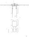
- Fig. 1 the distribution machine (1) is shown as a drawn sprayer, which is attached to a towing vehicle (2).
- a frame (3) is attached. This can have a device with the help of which the height of the frame (3) relative to the field sprayer (1) can be regulated.
- the frame (3) can also be rigidly connected to the field sprayer (1).
- the frame (3) is connected by means of a suspension device, here a pendulum suspension, which allows a substantially oriented in the direction of travel movement, with the central part (4) to which in turn the distributor linkage (6) is attached.
- a journal bearing by means of a sliding or linear ball bearing wherein the axis is oriented according to the direction of travel or a rail mounting.
- the in Fig. 1 shown middle part here is not essential to the invention and is assigned in the embodiment shown here the manifold linkage, since the distributor linkage is fixedly connected to the middle part and both movable relative to the frame by means of a suspension device (5), which is designed here as a pendulum guide is stored.
- the distributor linkage (6) can also be connected directly to the frame (3) via a bearing.
- the central part is associated with the frame and the distribution linkage is mounted via a movable suspension device movable relative to the central part and frame. It is also conceivable that between the frame and distribution linkage further parts of the distribution link or the frame can be assigned, which are connected to either the frame or the distributor linkage movable.
- the shuttle guide (5) of the distributor linkage (6) fulfills the purpose of making it movable parallel to the direction of travel R 1 and relative to the field sprayer (1) and its frame (3).
- the possible relative movement of the distributor linkage (6) and frame (3) can have further degrees of freedom.
- the bearing is designed, for example, as plain bearing or linear ball bearing along an axis lying in the direction of travel
- the distributor linkage (6) can additionally be rotated about the center of this axis in the direction of R 1 .
- the in Fig. 1 and Fig. 2 shown embodiment in which one side of the pendulum joint is designed as a ball head bearing. In a rail guide, however, this movement would be prevented.
- This also applies to another embodiment in which not one but two or more axles are used for guidance. Again, the rotational movement of the distributor linkage (6) about an axis parallel to R 1 would be prevented regardless of the storage on the axes.
- this is an acceleration sensor, but other sensors are conceivable, such as strain gauges or a speed sensor, which is used for the comparison of the current with a desired speed, so that future acceleration processes considered early for the scheme and the actuators and / or dampers corresponding the expected acceleration can be preconfigured.
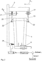
- Fig. 2 shown is a side view of the central part (4) and the frame (3).
- the central part (4) is in this case by means of a pendulum parallelogram suspension with two upper ball and socket joints (21) and two lower joints (22) and the two connecting the upper and lower joints pendulum rods (23) connected to the frame (3).
- the central part, to which the distributor linkage (6) is fixed designed to be movable in the direction of R 1 and pivotable about the axis A 2 through the ball joints.
- the storage takes place only via one or more than two bearings.
- the movement about the axis A 2 is not essential to the invention and can be prevented for example by appropriate multi-axis storage or rail guide.
- the control of the suspension device is provided as an active element (24).
- Data acquired by the sensor, not shown here, for example the acceleration, are compared as actual values with a desired value, for example by subtraction.
- the comparative value thus obtained is used in a control loop to generate an actuating signal which serves to control the active element and thus used to control the position of the central part (4) and thus indirectly of the distributor linkage, not shown here, attached to the central part, the control being instantaneous or quasi-instantaneously.
- the active element thus responds quasi without time delay or with minimal time delay on the data determined by the measuring device and prevents or damps the not shown here elastic bending or swinging of the ends of the distributor linkage.
- the active element (24) is shown here as a hydraulic cylinder. However, there are also any other forms of actuators conceivable, for example with a Pneumatic cylinder, a fluidic muscle, an electric motor or hydraulic motor.
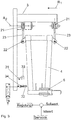
- FIG. 3 Another embodiment is in Fig. 3 shown.
- the central part (4) can be recognized, which is fastened to the frame (3) via the upper ball-and-socket joints (21), the lower joints (22) and the pendulum rods (23) connecting them.
- the active element has been replaced by a slowly active element (31). It consists of a spring element (32), for example a spiral spring, leaf spring or a hydraulic spring element, and a damper (33), which can be configured for example as a hydraulic or mechanical shock absorber, which between the frame (3) and the middle part (4).
- a spring element for example a spiral spring, leaf spring or a hydraulic spring element
- a damper which can be configured for example as a hydraulic or mechanical shock absorber, which between the frame (3) and the middle part (4).
- the comparative value thus obtained is used in a control loop to generate a control signal which serves to control the active element, here the spring base position by the double-acting cylinder, and thus to control the position of the central part (4) and thus indirectly of the distributor linkage not shown here ,
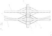
- Fig. 4 is exemplified the deflection of the sides of the distributor linkage (6) by an acceleration in the direction of R 4 acceleration.
- the distributor linkage (6) in this schematic diagram by two sliding bearings (41) and (42) on an axis along the direction of movement R 4 movably mounted.
- the described movements and bends can for a differently designed differently storage, such as the pendulum suspension in Fig. 2 and Fig. 3 be observed accordingly.
- An occurring acceleration can be caused for example by the start of the towing vehicle from the rest position.
- Shown is the distribution linkage (6), which is connected via the suspension device (44) with the front bearing (41) and the rear bearing (42).
- the front bearing (41) and the rear bearing (42) are in turn on the axis (43), arranged such that the distributor linkage (6) in and against the direction of travel R 4 relative to the axis (43) is displaceable.
- An onset of acceleration here exemplarily in the direction of R 4 , for example, by a starting operation of the towing vehicle, due to the flexibility of the manifold linkage (6) in conjunction with its dimensions and inertia, leads to an increasingly delayed acceleration towards the outer sides of the distributor linkage, which an elastic bending according to the position of the distributor linkage (6 ') and possibly induced thereby swinging up of the distributor linkage leads.
- This effect can be prevented or reduced by placing the linkage according to the position of the distribution linkage (6 ") depending on the thickness of the linkage Acceleration in the direction of R 5 moves and thus the occurring bending is encountered.
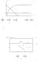
- Fig. 5 shows the speed of the field sprayer V field sprayer (t) as a function of time t when starting from the rest position
- the exact sequence of the acceleration process is not essential to the invention.
- the presented processes and processes for braking processes or accelerations apply from one movement.
- the acceleration course a frame (t) shown here applies to the field sprayer, the frame and also to a frame fixed to the frame linkage and takes place at time t 0 with maximum acceleration a 1 , which then decreases in a typical acceleration process the more the velocity v Field sprayer (t) approaches the target velocity v 0 .
- the acceleration is 0 m / s 2
- the speed of the field sprayer is then constant.
- the bending of the sides of a rigidly connected to the frame distributor linkage here depends directly on the acceleration occurring. The greater the acceleration, the greater the deflection of the distributor boom.
- the position of the distributor linkage (6) relative to the axle (43) during the acceleration process is also in FIG Fig. 5 shown.
- the distributor linkage (6) symbolized by the dashed line, for example in the center position (51) on the axis (43) (state A).
- This position is advantageous in order to mitigate acceleration processes in the direction R 4 and R 5 as well as possible, but also any other position on the axis (4) between the end points of the axis is conceivable as a starting position, although not in the same case for the case shown Dimensions suitable for damping occurring accelerations.
- the sensor-actuator combination of the invention ensures that acceleration acting on the distributor tube assembly (6) by moving the distributor tube assembly (6) on the axis (43) in which R 4 opposite direction R 5 is reduced.
- the distributor linkage (6) on the axis (43) for this purpose is counteracted towards the rear Direction R 4 moves (B).
- the position of the distributor linkage (6) on the axle (43) is in its extreme position (C) before being greater than t 2 , for example t 3, for times on the axis (43) in the direction of the central position (51) is moved forward (D), which is then reached at time t 4 .
- no more acceleration acts on the distributor linkage.
- control process other than the above-described control process are possible, for example, with successively decreasing or increasing acting on the manifold linkage (6) acceleration, which can act over a longer or shorter period than the acceleration of the towing vehicle (2) and the amount weaker or stronger than this one.
- short-term acceleration and / or braking operations may also be processes which are severely limited in time, as in the case illustrated in combination and thus caused bends and / or vibrations of the distributor linkage (6), which are caused, for example, by driving through a pothole.
- the speed of the traction vehicle (2) and / or the field sprayer (1) will change briefly when passing through the pothole and then preferably again assume the initial value, which was present before driving through the furrow.
- the acceleration of the distributor linkage (6) occurring as a result of the speed change and / or change in position of the field sprayer can be approximately prevented under these assumptions on the assumption that the control reacts instantaneously or quasi-instantly to the movement of the field sprayer, but at least considerably mitigates it.
- Fig. 6 shows by way of example the speed course v field sprayer (t) of the field sprayer when driving through a pothole.
- the speed of the field sprayer will increase briefly due to the acting acceleration by gravity and then reduce due to the force acting on the retraction braking effect of gravity approximately to the original value v const again.
- the shows Fig. 6 the course of the acceleration on the frame a frame (t), which when driving in a positive and positive when driving out of the pothole a negative acceleration Braking effect shows and influenced by the control acceleration of the distributor linkage (6) a Gestaenge (t), which can be reduced by the action of the sensor-actuator control to 0 m / s 2 .
- Vibrations can be integrated according to the invention by the consideration of acceleration and / or speed data and or position data and / or other parameters of the towing vehicle and / or field sprayer and / or the manifold linkage and / or in particular the boom of the manifold linkage in the control process, not only to prevent the bending, but also a swinging and / or swinging of the distributor linkage.
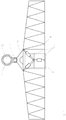
- FIG. 7 An embodiment according to the invention, which in addition to the displacement of the distributor linkage (6) relative to the frame (3) also allows a pendulum movement about the suspension point of a ball joint (71) is in Fig. 7 shown. Viewed from the manifold backside, the bearing shaft (72) is shown with the bearing (73) and the manifold linkage (6) attached to the suspension device (74). The pendulum movement is made possible by the ball joint (71) mounted between the suspension device (74) and the bearing (73). Actuators (75), which are exemplified here as double-acting hydraulic cylinders and mounted between the frame (3) and the distributor linkage (6), define a unique position of the distributor linkage (6) relative to the frame (3).
Landscapes
- Life Sciences & Earth Sciences (AREA)
- Engineering & Computer Science (AREA)
- Insects & Arthropods (AREA)
- Pest Control & Pesticides (AREA)
- Wood Science & Technology (AREA)
- Zoology (AREA)
- Environmental Sciences (AREA)
- Catching Or Destruction (AREA)
Description
Die vorliegende Erfindung betrifft eine Vorrichtung und ein Verfahren zur Bewegungssteuerung eines Verteilgestänges einer landwirtschaftlichen Verteilmaschine gemäß der Oberbegriffe der unabhängigen Patentansprüche 1 und 11.The present invention relates to an apparatus and a method for motion control of a distribution linkage of an agricultural distribution machine according to the preambles of
Feldspritzen, dies gilt sowohl für selbstfahrende als auch an Zugfahrzeuge wie Traktoren angehängte oder angebaute Feldspritzen, weisen mit ihrem Verteilergestänge, welches zur Verteilung des vorgesehenen Mittels dient, eine sehr große Arbeitsbreite, teilweise über 35 m, auf.Field sprayers, this applies to both self-propelled and attached to towing vehicles such as tractors or mounted field sprayers, with their distribution linkage, which serves to distribute the means provided, a very large working width, sometimes over 35 m on.
Auf Grund der üblicherweise im Zentrum des Verteilergestänges realisierten Befestigung am Rahmen der Feldspritze, kommt es zu einer starken elastischen Verbiegung des Gestänges, zu einem Aufschwingen oder zu Pendelbewegungen um das Zentrum desselben bei Beschleunigungen der Feldspritze. Die Beschleunigung, welche die Kräfte auf das Gestänge verursacht, können beispielsweise durch das Anfahren oder Abbremsen des Arbeitsgerätes, das Überfahren von Unebenheiten, wie Schlaglöchern oder Ackerfurchen, das Schwanken der Spritzbrühe im Tank der Feldspritze oder Kurvenfahrten hervorgerufen werden. Das Verbiegen und die unkontrollierte Bewegung der Seiten des Spritzgestänges, die durch die Beschleunigung hervorgerufen wird, versursacht eine unerwünschte ungleichmäßige Verteilung des mit der Feldspritze auszubringenden Mittels. Um diesem zu begegnen und die unkontrollierte Pendelbewegung des Gestänges der Feldspritze zu verhindern, sind aus dem Stand der Technik verschiedene Vorschläge bekannt.Due to the usually realized in the center of the distributor linkage attachment to the frame of the field sprayer, there is a strong elastic deflection of the linkage, to a swinging or oscillating movements around the center of the same during accelerations of the field sprayer. The acceleration that causes the forces on the linkage, for example, by the start or braking of the implement, the driving over bumps, such as potholes or furrows, the fluctuation of the spray mixture in the tank of the sprayer or cornering are caused. The bending and uncontrolled movement of the sides of the spray boom caused by the acceleration causes undesirable uneven distribution of the agent to be applied by the field sprayer. In order to counteract this and to prevent the uncontrolled pendulum movement of the boom of the field sprayer, various proposals are known from the prior art.
Nach
Eine zusätzliche Dämpfung und Kompensation einer Bewegung des Gestänges der Feldspritze um eine in Fahrtrichtung angeordnete Achse ist in
Nicht geeignet sind obige Maßnahmen um statt einer Drehbewegung oder Pendelbewegung des Verteilergestänges der Feldspritze eine Schwingbewegung in Fahrtrichtung desselben zu verhindern. Hierbei bewegen sich die gegenüberliegenden Seiten des Gestänges relativ zum Zentrum des Gestänges zumindest annähernd phasengleich oder anders ausgedrückt gleichzeitig in gleicher Richtung in und entgegen der Fahrtrichtung der Feldspritze. Ursache solcher Bewegungen können, wie oben erwähnt, beispielsweise die durch das Anfahren, Erhöhen der Geschwindigkeit der Arbeitsmaschine oder Abbremsen hervorgerufenen Beschleunigungen sein. Es können aber auch Wankbewegungen der Feldspritze auf Grund von Unebenheiten des Untergrunds oder eines schwankenden Flüssigkeitspegels der Spritzbrühe im Inneren des Feldspritzentanks oder sonstige zur Anregung einer solchen Bewegung geeignete Ursachen der Bewegung des Spritzgestänges vorliegen.The above measures are not suitable for preventing a swinging movement in the direction of travel of the field sprayer instead of a rotary movement or pendulum movement of the distributor linkage. Here, the opposite sides of the linkage move relative to the center of the linkage at least approximately in-phase or in other words simultaneously in the same direction in and against the direction of travel of the field sprayer. Cause of such movements, as mentioned above, for example, be caused by the start, increase the speed of the working machine or braking accelerations. However, it may also be rolling movements of the sprayer due to unevenness of the ground or a fluctuating liquid level of the spray mixture in the interior of the field spray tank or other suitable for the stimulation of such movement causes the movement of the sprayer boom.
Die zuvor aufgeführten Ausgestaltungen sind geeignet Dreh- oder Pendelbewegungen um die Aufhängung des Verteilergestänges der Feldspritze zu dämpfen oder zu verhindern, nicht aber etwaig auftretende Schwingbewegungen. Eine Dämpfung der beschriebenen Schwingbewegung des Gestänges der Feldspritze ist in
Vorteilhafter wäre es durch ein kontrolliertes Bewegen des Gestänges der Feldspritze relativ zum Rahmen das Auftreten der Beschleunigungskräfte zu verhindern oder zu minimieren. Eine entsprechende, wenn auch nachteilsbehaftete Technik, die das Auftreten einer solchen Bewegung verhindert, realisiert mit Hilfe von Schwingungstilgern, ist allein in der
Aufgabe der vorliegenden Erfindung ist es dementsprechend ein Biegen und/oder Aufschwingen des Verteilgestänges einer landwirtschaftlichen Feldspritze hervorgerufen durch Beschleunigungen der Feldspritze zu dämpfen oder zu verhindern.The object of the present invention is accordingly to dampen or prevent bending and / or swinging up of the distribution linkage of an agricultural field sprayer caused by accelerations of the field sprayer.
Dies wird durch eine Bewegungsvorrichtung gemäß dem Oberbegriff des Anspruchs 1 zur Dämpfung und/oder Verhinderung von elastischen Gestängebiegungen und/oder Schwingungen sowie durch ein Verfahren zur Steuerung einer solchen Bewegungsvorrichtung gemäß dem Oberbegriff des Anspruchs 11 erreicht, welche zwischen dem Rahmen und dem Verteilergestänge angeordnet ist. Hierdurch kann auf einfache und platzsparende Art und Weise ein Aufschwingen und/oder elastisches Biegen des Verteilergestänges verhindert werden.This is achieved by a movement device according to the preamble of
Erreicht wird kann dies, indem eine Abstandsänderung zwischen Verteilergestänge und Rahmen, vorgenommen durch ein oder mehrere Aktoren erfolgt. Hierbei kann zum Beispiel die Abstandsänderung auch durch eine entsprechende Krafteinwirkung auf den Fußpunkt einer zwischen Verteilergestänge und Rahmen angebrachten Spiralfeder erfolgen.This can be achieved by a change in distance between manifold frame and frame, made by one or more actuators. Here, for example, the change in distance by a corresponding force on the base of a mounted between the manifold frame and frame coil spring done.
Die Einstellung des Abstands zwischen Verteilergestänge und Rahmen kann durch verschiedene Arten von Aktoren, wie beispielsweise Hydraulikzylinder, Pneumatikzylinder, fluidischen Muskeln, Elektromotoren oder Hydraulikmotoren und dergleichen, erfolgen.Adjustment of the distance between the manifold linkage and the frame may be accomplished by various types of actuators, such as hydraulic cylinders, pneumatic cylinders, fluidic muscles, electric motors or hydraulic motors, and the like.
In einer vorteilhaften Weiterbildung erfolgt die Minimierung der elastischen Verbiegung des Verteilergestänges durch die mittels Regulation der Federfußpunktposition einer zwischen Verteilergestänge und Rahmen angeordneten Kombination eines Feder- und eines Dämpferelementes realisierte Einstellung des Abstandes zwischen dem Verteilergestänge und dem Rahmen. Der Vorteil hierbei liegt in der passiven Dämpfung hoher Frequenzen, beispielsweise größer als 5 Hz, durch das Feder-Dämpfer-System, während niedrige Frequenzen, von beispielsweise 5 Hz oder weniger, mit einer aktiven Abstandregulation mit Hilfe der Federfußpunktverstellung gedämpft werden. Die Verwendung einer Kombination von Dämpfer und Feder mit Fußpunktverstellung ermöglicht niedrigere Anforderungen an die Regelungsgeschwindigkeit, da hohe Schwingungsfrequenzen des Verteilergestänges durch das passive Dämpfungsverhalten des Feder-Dämpfer-Systems effektiv minimiert werden.
Die Feder kann hierbei beispielsweise als Spiralfeder ausgestaltet sein und der Dämpfer als hydraulisches oder mechanisches Dämpfungselement.
In einer vorteilhaften Weiterbildung der Erfindung ist die Regelung des Abstands zwischen dem Verteilergestänge und dem Rahmen mit Hilfe von durch an dem Verteilergestänge und/oder dem Rahmen und/oder der Feldspritze und/oder der Zugmaschine angeordnete Sensoren erfasste Beschleunigungsdaten und/oder Geschwindigkeitsdaten der Feldspritze und/oder des Verteilergestänges und oder des Zugfahrzeugs vornehmbar. Hierdurch kann direkt auf Informationen, welche aus Beschleunigungs- und/oder Geschwindigkeitsdaten aufgenommen am Gestänge und/oder der Feldspritze und/oder der Zugmaschine oder deren Kombination gewonnen werden, geregelt werden.In an advantageous refinement, the elastic deflection of the distributor linkage is minimized by the adjustment of the distance between the distributor linkage and the frame realized by means of regulation of the spring base position of a combination of a spring element and a damper element arranged between distributor linkage and frame. The advantage here is in the passive attenuation of high frequencies, for example, greater than 5 Hz, by the spring-damper system, while low frequencies, for example, 5 Hz or less, are damped with an active distance regulation using the Federfußpunktverstellung. The use of a damper / spring combination with foot point adjustment allows lower control speed requirements, as high vibration frequencies of the manifold linkage are effectively minimized by the passive damping behavior of the spring / damper system.
The spring may in this case be configured for example as a spiral spring and the damper as a hydraulic or mechanical damping element.
In an advantageous development of the invention, the regulation of the distance between the distributor linkage and the frame by means of acceleration sensors and / or speed data of the field sprayer detected by sensors arranged on the distributor linkage and / or the frame and / or the field sprayer and / or the tractor / or the distribution linkage and or the towing vehicle vornehmbar. As a result, it is possible to directly control information which is obtained from acceleration and / or speed data recorded on the boom and / or the field sprayer and / or the tractor or their combination.
In einer vorteilhaften Weiterbildung der Erfindung wird die Stärke und/oder Frequenz der Biegung und/oder Schwingung des Verteilergestänges mit Hilfe von Beschleunigungssensoren oder Dehnungsmessstreifen, welche an den Verteilergestängeauslegern, vorzugweise in der Nähe des äußersten Endes der Ausleger, und zumindest annähernd im Zentrum des Gestänges oder am Rahmen oder an der Feldspritze angebracht sind, bestimmt und diese Information zur Regelung des Abstands zwischen Verteilergestänge und Rahmen verwendet. Dies ermöglicht eine exakte Bestimmung der Relativbewegung und/oder - beschleunigung der Gestängeausleger relativ zum Zentrum des Gestänges.
In einer vorteilhaften Weiterbildung ist der Abstand zwischen dem Verteilergestänge und dem Rahmen mit Hilfe von durch Sensoren erfasste Geschwindigkeitsdaten der Feldspritze/eines Zugfahrzeugs und dem Vergleich dieser zu einer hinterlegten Sollgeschwindigkeit regulierbar. Dies ermöglicht zukünftige Beschleunigungsvorgänge bereits frühzeitig zu berücksichtigen.
Die Position des Verteilergestänges ist dabei in einer möglichen Ausgestaltung nur im Abstand zwischen Rahmen und Verteilergestänge variabel und ansonsten ortsfest.In an advantageous embodiment of the invention, the strength and / or frequency of the bending and / or vibration of the distributor linkage by means of acceleration sensors or strain gauges, which at the Verteilergestängeauslegern, preferably in the vicinity of the outermost end of the boom, and at least approximately in the center of the linkage or attached to the frame or to the field sprayer, and uses this information to control the distance between the manifold linkage and the frame. This allows an accurate determination of the relative movement and / or acceleration of the boom extension relative to the center of the linkage.
In an advantageous development, the distance between the distributor linkage and the frame can be regulated with the aid of speed data of the field sprayer / a towing vehicle detected by sensors and the comparison of these to a stored setpoint speed. This allows future acceleration processes to be considered early on.
The position of the distributor linkage is variable in a possible embodiment only at the distance between the frame and distributor linkage and otherwise stationary.
In einer vorteilhaften Weiterbildung der Erfindung ist der Abstand des Verteilergestänges relativ zum Rahmen, an dem es befestigt ist, variabel und zusätzlich um eine im Wesentlichen in Fahrtrichtung liegende Achse drehbar aufgehängt. Hierdurch kann ein Ausgleich der Verteilergestängeposition an die Neigung des Geländes in vorteilhafter Weise mit der Dämpfung von Schwing- und/oder Biegebewegungen des Verteilergestänges kombiniert werden.
Eine entsprechende Lagerung des Verteilergestänges an dem Rahmen kann beispielsweise mit Hilfe von Gleit- oder Linearkugellagern oder einer pendelartigen Aufhängung des Verteilergestänges am Rahmen erreicht werden.
In einer weiteren vorteilhaften Ausgestaltung ist eine Rotation um eine im Wesentlichen senkrecht liegende Achse möglich. Hierdurch kann durch die Kombination mit geeigneten Einstellmitteln eine Dämpfung von Pendelbewegungen um ebenjene Achse bewerkstelligt und in vorteilhafter Weise mit der Dämpfung von Schwing- und/oder Biegebewegungen des Verteilergestänges erreicht werden.In an advantageous embodiment of the invention, the distance of the distributor linkage relative to the frame to which it is attached, variable and in addition rotatably suspended about an axis lying substantially in the direction of travel axis. In this way, a compensation of the distributor linkage position to the inclination of the terrain can be advantageously combined with the damping of oscillatory and / or bending movements of the distributor linkage.
A corresponding mounting of the distributor linkage to the frame can be achieved for example by means of sliding or linear ball bearings or a pendulum-type suspension of the distributor linkage on the frame.
In a further advantageous embodiment, a rotation about an axis lying substantially perpendicular is possible. This can be accomplished by the combination of suitable adjusting means damping of oscillations about the same axis and be achieved in an advantageous manner with the damping of oscillatory and / or bending movements of the distributor linkage.
Eine solche Bewegung ist beispielsweise mit Hilfe einer Kugelgelenkaufhängung zusätzlich zu der die Translationsbewegung des Verteilergestänges übertragenden Lagerung realisierbar, wobei zusätzlich zu der Rotation um eine senkrechte Achse auch eine Rotation um eine waagerechte Achse vorgesehen sein kann.Such a movement can be realized, for example, with the aid of a ball joint suspension in addition to the bearing transmitting the translatory movement of the distributor linkage, whereby in addition to the rotation about a vertical axis, a rotation about a horizontal axis can also be provided.
In einer vorteilhaften Weiterbildung erfolgt die Einstellung des Abstands zwischen Rahmen und Verteilergestänge mit Hilfe eine Hexapods, so dass eine Rotation des Verteilergestänges um drei senkrechte Achsen und zusätzlich eine Translationsbewegung entlang ebenjener Achsen möglich ist.
Hierdurch können die Geländeneigung ausgeglichen, sowie Pendel- und Schwingbewegungen des Verteilergestänges gedämpft werden.In an advantageous development, the adjustment of the distance between the frame and distributor linkage by means of a hexapod, so that a rotation of the distributor linkage about three vertical axes and in addition a translational movement along ebenjener axes is possible.
As a result, the terrain slope can be compensated, as well as damped pendulum and swinging movements of the manifold linkage.
Das Dämpfen oder Verhindern eines Biegens oder Aufschwingens eines Verteilergestänges einer Feldspritze wird zudem durch das Verfahren gemäß Anspruch 11 ermöglicht, indem eine zwischen Verteilergestänge und Rahmen angeordnete Bewegungsvorrichtung angesteuert wird.The damping or prevention of bending or swinging of a distributor boom of a field sprayer is also made possible by the method according to claim 11, by controlling a movement device arranged between distributor rod and frame.
Weitere vorteilhafte Ausgestaltungen ergeben sich aus den Verfahrensansprüchen 12 bis 18 und den Beschreibungen und den Figuren.
- Fig. 1
- zeigt die Feldspritze mit an einem Rahmen befestigtem Verteilergestänge angehängt an ein Zugfahrzeug.
- Fig. 2
- zeigt eine seitliche Ansicht des Verteilergestänges, wobei der Abstand zwischen Verteilergestänge und Rahmen mit Hilfe eines aktiven Elements gesteuert wird.
- Fig. 3
- zeigt eine seitliche Ansicht des Verteilergestänges, wobei der Abstand zwischen Verteilergestänge und Rahmen mit Hilfe eines halbaktiven Elements gesteuert wird.
- Fig. 4
- zeigt beispielhaft die Verbiegung des Verteilergestänges hervorgerufen durch eine Beschleunigung der Feldspritze.
- Fig. 5
- zeigt beispielhaft die Beschleunigung der Feldspritze bei einem Beschleunigungsvorgang der Zugmaschine und die durch die Abstandsregelung beeinflusste Beschleunigung des Verteilergestänges sowie die Position des Verteilergestänges zu verschiedenen Zeitpunkten der Beschleunigung bzw. Regelung.
- Fig. 6
- zeigt beispielhaft die Beschleunigung der Feldspritze beim Durchfahren einer Ackerfurche und die durch die Abstandsregelung beeinflusste Beschleunigung des Verteilergestänges sowie die Position des Verteilergestänges zu verschiedenen Zeitpunkten der Beschleunigung bzw. Regelung.
- Fig. 7
- zeigt eine beispielhafte Kopplung des Verteilergestänges an den Rahmen mit Hilfe eines Pendelgelenkes und dreier Hydraulikzylinder
- Fig. 1
- shows the field sprayer attached to a frame distribution linkage attached to a towing vehicle.
- Fig. 2
- shows a side view of the manifold linkage, wherein the distance between the manifold linkage and frame is controlled by means of an active element.
- Fig. 3
- shows a side view of the manifold linkage, wherein the distance between the manifold linkage and frame is controlled by means of a semi-active element.
- Fig. 4
- shows by way of example the bending of the distributor boom caused by an acceleration of the field sprayer.
- Fig. 5
- shows by way of example the acceleration of the field sprayer during an acceleration process of the tractor and the influence of the distance control influenced acceleration of the distributor linkage and the position of the distributor linkage at different times of the acceleration or control.
- Fig. 6
- shows, by way of example, the acceleration of the field sprayer when driving through a furrow and the acceleration of the distributor boom influenced by the distance control and the position of the distributor boom at different points in time of the acceleration or control.
- Fig. 7
- shows an exemplary coupling of the distributor linkage to the frame by means of a pendulum joint and three hydraulic cylinders
In
Die Pendelführung (5) des Verteilergestänges (6) erfüllt den Zweck, dieses parallel zur Fahrtrichtung R1 und relativ zur Feldspritze (1) und dessen Rahmen (3) beweglich zu gestalten. Abhängig davon, wie die Lagerung bzw. Verbindung zwischen Verteilergestänge (6) und Rahmen (3) ausgestaltet ist, kann die mögliche Relativbewegung von Verteilergestänge (6) und Rahmen (3) weitere Freiheitsgrade aufweisen. Ist die Lagerung beispielsweise als Gleitlager oder Linearkugellager entlang einer in Fahrtrichtung liegenden Achse ausgebildet, so kann das Verteilergestänge (6) um das Zentrum dieser Achse in Richtung R1 zusätzlich gedreht werden. Gleiches gilt für die in
Das Einstellen der Position des Verteilergestänges (6) in der Fahrtrichtung R1 und ebenso die Antwort auf auftretende oder zu erwartende Beschleunigungen erfolgt über eine in
In
Eine andere Ausgestaltung ist in
Dieser Aufbau hat gegenüber der in
In
Eine einsetzende Beschleunigung, hier beispielhaft in Richtung R4, beispielsweise durch einen Anfahrvorgang des Zugfahrzeugs, führt wegen der Flexibilität des Verteilergestänges (6) in Verbindung mit seinen Dimensionen und der Massenträgheit, zu einer zunehmend verzögerten Beschleunigung hin zu den Außenseiten des Verteilergestänges, was zu einer elastischen Verbiegung entsprechend der Lage von Verteilergestänge (6') und einem eventuell dadurch induzierten Aufschwingen des Verteilergestänges führt. Dieser Effekt kann verhindert oder vermindert werden, indem das Gestänge entsprechend der Lage von Verteilergestänge (6") in Abhängigkeit der Stärke der auftretenden Beschleunigung in Richtung R5 bewegt und somit der auftretenden Verbiegung begegnet wird.An onset of acceleration, here exemplarily in the direction of R 4 , for example, by a starting operation of the towing vehicle, due to the flexibility of the manifold linkage (6) in conjunction with its dimensions and inertia, leads to an increasingly delayed acceleration towards the outer sides of the distributor linkage, which an elastic bending according to the position of the distributor linkage (6 ') and possibly induced thereby swinging up of the distributor linkage leads. This effect can be prevented or reduced by placing the linkage according to the position of the distribution linkage (6 ") depending on the thickness of the linkage Acceleration in the direction of R 5 moves and thus the occurring bending is encountered.
Bei anhaltenden Beschleunigungsvorgängen, beispielsweise beim Anfahren oder bei einer Erhöhung der Geschwindigkeit des Zugfahrzeugs, bewirkt dieser Mechanismus eine Dämpfung der auftretenden Verbiegung und evtl. hierdurch angeregter Schwingungen. Da das Verteilergestänge (6) letztlich unumgänglich auf die Geschwindigkeit des Zugfahrzeugs beschleunigt werden muss, können die Auswirkungen einer monotonen Beschleunigung auf die Lage und/oder Form des Verteilergestänges nur gedämpft, nicht aber gänzlich verhindert werden.In the case of sustained acceleration processes, for example when starting or increasing the speed of the towing vehicle, this mechanism causes a damping of the bending occurring and possibly vibrations excited thereby. Since the distribution linkage (6) ultimately inevitably has to be accelerated to the speed of the towing vehicle, the effects of a monotonous acceleration on the position and / or shape of the distributor linkage can only be damped, but not completely prevented.
Um die auf das Verteilergestänge (6) wirkende Beschleunigung aRahmen(t) zu verringern, kann nun, wie in
Um das Verteilergestänge (6) während der gesamten Beschleunigungsphase mit zumindest annähernd gleicher Beschleunigung aGestänge(t) zu versehen und letztlich auf die Geschwindigkeit der Feldspritze zu beschleunigen, ist es zweckmäßig das Verteilergestänge zum Schluss dieses Prozesses relativ zur Achse nach vorne in die Ausgangsposition zu bewegen. Der Vorteil dieses Verfahrens ist, dass das Verteilergestänge (6) einer geringeren Beschleunigungswirkung ausgesetzt ist, die entsprechend über einen, im Vergleich zum Beschleunigungsvorgang des Zugfahrzeugs (2), längeren Zeitraum wirkt. Somit ist die maximale Verbiegung der Seiten des Verteilergestänges (6) aus der Ruhelage geringer.In order to reduce the acceleration a frame (t) acting on the distributor linkage (6), as shown in FIG
In order to provide the distributor linkage (6) with at least approximately the same acceleration a linkage (t) during the entire acceleration phase and ultimately to accelerate the speed of the field sprayer, it is expedient for the distributor linkage to be in the starting position at the end of this process relative to the axis move. The advantage of this method is that the distributor linkage (6) is exposed to a lower acceleration effect, which accordingly acts over a longer period of time compared to the acceleration process of the towing vehicle (2). Thus, the maximum deflection of the sides of the distributor linkage (6) from the rest position is lower.
Die Position des Verteilergestänges (6) relativ zu der Achse (43) während des Beschleunigungsprozesses ist ebenfalls in
Demgegenüber sind kurzeitige Beschleunigungs- und/oder Bremsvorgänge eventuell auch wie im dargestellten Fall in Kombination und dadurch hervorgerufene Biegungen und/oder Schwingungen des Verteilergestänges (6), die beispielsweise durch ein Durchfahren eines Schlagloches verursacht werden zeitlich stark eingegrenzte Prozesse. Die Geschwindigkeit des Zugfahrzeugs (2) und/oder der Feldspritze (1) wird sich beim Durchfahren des Schlaglochs kurzeitig ändern und dann vorzugsweise wieder den Ausgangswert einnehmen, der vor dem Durchfahren der Furche vorlag. Die durch die Geschwindigkeitsänderung und/oder Lageänderung der Feldspritze beim Durchfahren der Furche eintretende Beschleunigung des Verteilergestänges (6) lässt sich bei diesen Vorgängen annähernd verhindern unter der Annahme, dass die Regelung instantan oder quasiinstantan auf die Bewegung der Feldspritze reagiert, zumindest jedoch erheblich abmildern.On the other hand, short-term acceleration and / or braking operations may also be processes which are severely limited in time, as in the case illustrated in combination and thus caused bends and / or vibrations of the distributor linkage (6), which are caused, for example, by driving through a pothole. The speed of the traction vehicle (2) and / or the field sprayer (1) will change briefly when passing through the pothole and then preferably again assume the initial value, which was present before driving through the furrow. The acceleration of the distributor linkage (6) occurring as a result of the speed change and / or change in position of the field sprayer can be approximately prevented under these assumptions on the assumption that the control reacts instantaneously or quasi-instantly to the movement of the field sprayer, but at least considerably mitigates it.
Für die in
Eine erfindungsgemäße Ausgestaltung, welche neben der Verschiebung des Verteilergestänges (6) relativ zum Rahmen (3) auch eine Pendelbewegung um den Aufhängepunkt eines Kugelgelenks (71) zulässt ist in
Weitere mögliche Ausgestaltungen, die die Kombination von Translations und Rotationsbewegungen, beispielsweise durch die Verwendung eines Hexapods, ermöglichen, sind denkbar.Other possible embodiments that allow the combination of translational and rotational movements, for example by the use of a hexapod, are conceivable.
Claims (18)
- Distributor rod system (6) of an agricultural field spray (1), which distributor rod system has an extent perpendicularly to the direction of travel and is mounted, by means of a suspension device (5) which permits movement of the entire distributor rod system (6) is approximately in the direction of travel, so as to be movable with respect to the frame (3) to which it is attached, wherein a movement device for damping and/or preventing elastic rod system bending, occurring at least approximately in the direction of travel is arranged between the frame and the distributor rod system,
characterized
in that one or more actuators which are arranged between the frame (3) and the distributor rod system (6) are provided, said actuators bringing about damping and/or preventing the elastic bending of the distributor rod system (6), caused by the dynamics of the field spray, by changing the distance between the distributor rod system (6) and the frame (3). - Distribution rod system according to Claim 1,
characterized in that a combination of a spring element (32) and a damper element (34) is provided between the distribution rod system (6) and the frame (3), which combination brings about the damping and/or changing of the elastic bending of the distribution rod system (6) by means of the adjustment of the distance between the distribution rod system and the frame (3) which is carried out by regulating the spring base point position. - Distribution rod system according to at least one of Claims 1 and 2, characterized in that sensors (7) are provided on the distribution rod system and/or the frame and/or the field spray (1) and/or the traction vehicle (2), with the result that the regulation of the distance between the distribution rod system (6) and the frame (3) can be performed using acceleration data and/or speed data, acquired by means of the sensors, of the field spray (1) and/or of the distribution rod system (6) and/or of the traction vehicle (2).
- Distribution rod system according to at least one of Claims 1 to 3, characterized in that acceleration sensors or strain gauges which are attached to the distribution rod system booms, preferably in the vicinity of the outermost end of the booms, and are at least approximately in the centre of the rod system or on the frame or on the field spray which determine the strength and/or frequency of the bending and/or vibration of the distribution rod system (6), and this information can be used to regulate the distance between the distribution rod system (6) and the frame (3).
- Distribution rod system according to at least one of Claims 3 and 4, characterized in that sensors for acquiring speed data of the field spray/of a traction vehicle are arranged on the field spray (1) or the traction vehicle (2), and the distance between the distribution rod system (6) and the frame (3) can be regulated using this data and the comparison of the latter with a stored setpoint speed.
- Distribution rod system according to at least one of the preceding claims, characterized in that the distribution rod system is embodied in such a way that the shifting of the distribution rod system (6) relative to the frame (3) is the only degree of freedom of the distribution rod system (6).
- Distribution rod system according to at least one of Claims 1-5, characterized in that the distribution rod system (6) is arranged so as to be shiftable along an axis lying in the direction of travel, and is mounted so as to be additionally rotatable about this axis.
- Distribution rod system according to at least one of Claims 1-5, characterized in that the distribution rod system is embodied in such a way that in addition to the distance of the distribution rod system (6) from the frame (3), the distribution rod system can additionally rotate about an axis lying in the direction of travel and an axis lying perpendicularly with respect thereto.
- Distribution rod system according to Claim 9, characterized in that a pendulum suspension system (71) and three double-acting cylinders (75) are provided which transmit the translational movement and rotational movement.
- Distribution rod system according to at least one of the preceding claims, characterized in that the suspension device at the same time constitutes the movement device, in particular in an arrangement composed of six hydraulic cylinders, which arrangement permits, as a hexapod, three translational degrees of freedom and three rotational degrees of freedom.
- Method for controlling the movement of a distribution rod system (6) of an agricultural field spray (1), which distribution rod system has an extent perpendicular with respect to the direction of travel and is mounted, by means of a suspension device (5) which permits movement of the entire distribution rod system (6) at least approximately in the direction of travel, so as to be movable with respect to the frame (3) to which it is attached, wherein damping and/or preventing of elastic rod system bending occurring at least approximately in the direction of travel are permitted by controlling a movement device which is arranged between the frame and the distribution rod system (6),
characterized
in that the damping and/or prevention of the elastic bending of the distribution rod system (6) are caused by the dynamics of the field spray (1) and are carried out by changing the distance between the frame (3) and the distribution rod system (6). - Method according to Claim 11, characterized in that the damping and/or prevention of the elastic bending of the distribution rod system (6) are achieved by adjusting the distance between the distribution rod system (6) and the frame (3), said adjustment being implemented by regulating the spring base point position of a combination of a spring element (32) and a damp element (34) which is arranged between the distribution rod system (6) and frame (3).
- Method according to at least one of Claims 11 or 12, characterized in that the distance between the distribution rod system (6) and the frame (3) is adjusted using acceleration data and/or speed data of the field spray (1) and/or of the distribution rod system (6) and/or of the traction vehicle (2).
- Method according to at least one of Claims 11 to 13, characterized in that the degree and/or frequency of the bending and/or oscillation of the distribution rod system (6) are determined using acceleration data recorded on the distribution rod system booms, preferably in the vicinity of the outermost end of the booms, and at least approximately in the centre of the rod system or on the frame or on the field spray (1), and this information can be used to regulate the distance between the distribution rod system (6) and the frame (3).
- Method according to at least one of Claims 13 or 14, characterized in that the distance between the distribution rod system (6) and the frame (3) is regulated using speed data of the field spray (1) and/or of a traction vehicle (2) and the comparison of said data with a stored setpoint speed.
- Method according to at least one of Claims 11 to 15, characterized in that the shifting of the distribution rod system (6) relative to the frame (3) is the single degree of freedom of the distribution rod system (6).
- Method according to at least one of Claims 11 to 15, characterized in that the distribution rod system (6) is arranged so as to be shiftable along an axis lying in the direction of travel and is mounted so as to be additionally rotatable about this axis.
- Method according to at least one of Claims 11-15,
characterized in that in addition to the distance of the distribution rod system (6) from the frame (3), the distribution rod system (6) can additionally be rotated about an axis lying in the direction of travel and an axis lying perpendicularly with respect thereto.
Priority Applications (1)
| Application Number | Priority Date | Filing Date | Title |
|---|---|---|---|
| PL15401080T PL2982243T3 (en) | 2014-08-05 | 2015-08-03 | Device and method for controlling the motion of a distribution rod system of an agricultural distributor |
Applications Claiming Priority (1)
| Application Number | Priority Date | Filing Date | Title |
|---|---|---|---|
| DE102014111090.0A DE102014111090A1 (en) | 2014-08-05 | 2014-08-05 | Device and method for the motion control of a distributor linkage of an agricultural distribution machine |
Publications (2)
| Publication Number | Publication Date |
|---|---|
| EP2982243A1 EP2982243A1 (en) | 2016-02-10 |
| EP2982243B1 true EP2982243B1 (en) | 2018-01-31 |
Family
ID=53800936
Family Applications (1)
| Application Number | Title | Priority Date | Filing Date |
|---|---|---|---|
| EP15401080.5A Active EP2982243B1 (en) | 2014-08-05 | 2015-08-03 | Device and method for controlling the motion of a distribution rod system of an agricultural distributor |
Country Status (4)
| Country | Link |
|---|---|
| EP (1) | EP2982243B1 (en) |
| DE (1) | DE102014111090A1 (en) |
| DK (1) | DK2982243T3 (en) |
| PL (1) | PL2982243T3 (en) |
Families Citing this family (6)
| Publication number | Priority date | Publication date | Assignee | Title |
|---|---|---|---|---|
| DE102016110364A1 (en) | 2016-06-06 | 2017-12-07 | Amazonen-Werke H. Dreyer Gmbh & Co. Kg | Control and / or control system, agricultural machine and method for controlling and / or regulating an agricultural machine |
| DE102016114418A1 (en) * | 2016-08-04 | 2018-02-08 | Amazonen-Werke H. Dreyer Gmbh & Co. Kg | Distributor linkage, agricultural utility vehicle and method of making a manifold linkage |
| DE102017201918A1 (en) * | 2017-02-07 | 2018-08-09 | Deere & Company | Agricultural distribution machine with automatic control of the damping of the distribution linkage |
| DE102017114637A1 (en) | 2017-06-07 | 2018-12-13 | Amazonen-Werke H. Dreyer Gmbh & Co. Kg | Sprayer for an agricultural sprayer. Flow rate control |
| DE102017118302A1 (en) * | 2017-08-11 | 2019-02-14 | Amazonen-Werke H. Dreyer Gmbh & Co. Kg | Control and / or regulating system, agricultural utility vehicle and method for controlling and / or regulating an agricultural utility vehicle |
| CN108782527A (en) * | 2018-06-22 | 2018-11-13 | 苏州仁益生物科技有限公司 | A kind of packaged type agricultural planting irrigation rig |
Family Cites Families (7)
| Publication number | Priority date | Publication date | Assignee | Title |
|---|---|---|---|---|
| FR2530498A1 (en) * | 1982-07-26 | 1984-01-27 | Sba Chimie | DEVICE FOR MOUNTING RAMPS ADAPTED ON AGRICULTURAL AND INDUSTRIAL MATERIALS, IN PARTICULAR SPRAY RAMPS |
| US4646972A (en) * | 1984-10-22 | 1987-03-03 | Cedar Valley Products, Inc. | Spring mounted spray boom structure |
| DE20018716U1 (en) | 1999-11-04 | 2001-03-29 | Inuma Fahrzeug Service Und Mas | Device for attaching sprayer booms to agricultural vehicles |
| DE10054285B4 (en) | 2000-11-02 | 2014-12-24 | Amazonen-Werke H. Dreyer Gmbh & Co. Kg | distributing |
| DE102007025751B4 (en) | 2007-06-01 | 2022-08-25 | Amazonen-Werke H. Dreyer SE & Co. KG | distribution machine |
| DE102008007312A1 (en) | 2008-02-02 | 2009-08-06 | Amazonen-Werke H. Dreyer Gmbh & Co. Kg | Distributor rod for use on frame of agricultural distribution machine, has vibration damper positioned in laterally outer area of rod, where damper is not connected with frame of agricultural distribution machine |
| PL2591657T3 (en) | 2011-11-08 | 2017-12-29 | Horsch Leeb Application Systems Gmbh | Moveable device for dispensing fluid and/or solid substances and method for controlling the device |
-
2014
- 2014-08-05 DE DE102014111090.0A patent/DE102014111090A1/en not_active Withdrawn
-
2015
- 2015-08-03 DK DK15401080.5T patent/DK2982243T3/en active
- 2015-08-03 EP EP15401080.5A patent/EP2982243B1/en active Active
- 2015-08-03 PL PL15401080T patent/PL2982243T3/en unknown
Non-Patent Citations (1)
| Title |
|---|
| None * |
Also Published As
| Publication number | Publication date |
|---|---|
| DE102014111090A1 (en) | 2016-02-11 |
| EP2982243A1 (en) | 2016-02-10 |
| PL2982243T3 (en) | 2018-07-31 |
| DK2982243T3 (en) | 2018-05-07 |
Similar Documents
| Publication | Publication Date | Title |
|---|---|---|
| EP2982243B1 (en) | Device and method for controlling the motion of a distribution rod system of an agricultural distributor | |
| EP2829177B1 (en) | Agricultural spreader machine with distribution device and system for controlling the distribution device | |
| EP3065530B1 (en) | Apparatus for discharging liquid and/or solid active substances and method for controlling such an apparatus | |
| EP3219187B1 (en) | Moveable device for dispensing fluid and/or solid substances and method for controlling the device | |
| DE602004004297T2 (en) | System and method for roll control of a suspended boom | |
| EP2837285B1 (en) | Spray-boom of an agricultural field sprayer | |
| EP3337317B1 (en) | Boom suspension for agricultural machine | |
| DE102007047886A1 (en) | spray boom | |
| EP3634124B1 (en) | Spray boom | |
| EP2526755A1 (en) | Agricultural distribution machine | |
| EP3141114B1 (en) | Agricultural sprayer and method | |
| DE202013011983U1 (en) | Sprayer boom of an agricultural sprayer | |
| EP3440932B1 (en) | Active vibration damping | |
| DE102006023603B4 (en) | Device and method for compensating a dynamic yawing moment | |
| EP3308644A1 (en) | Regulation and/or control system for an agricultural machine | |
| DE102018103862A1 (en) | Suspension for an agricultural machine and method for operating an agricultural machine | |
| EP2526756B1 (en) | Agricultural distribution machine with sprayboom | |
| DE1269902B (en) | Method and device for controlling a vehicle suspension, in particular in off-road vehicles | |
| EP3753407A1 (en) | Agricultural implement with improved inclination control | |
| EP3798028B1 (en) | Agricultural machine and method for steering an agricultural machine | |
| EP4212018A1 (en) | Agricultural implement with improved inclination control | |
| DE102008017058B4 (en) | Side control for a vibration plate | |
| DE102022124012A1 (en) | Agricultural harvesting machine, particularly in the form of a front-mounted mower | |
| DE102022131013A1 (en) | Agricultural harvester | |
| WO2008017371A1 (en) | Method for ballasting and stabilization of a track |
Legal Events
| Date | Code | Title | Description |
|---|---|---|---|
| PUAI | Public reference made under article 153(3) epc to a published international application that has entered the european phase |
Free format text: ORIGINAL CODE: 0009012 |
|
| AK | Designated contracting states |
Kind code of ref document: A1 Designated state(s): AL AT BE BG CH CY CZ DE DK EE ES FI FR GB GR HR HU IE IS IT LI LT LU LV MC MK MT NL NO PL PT RO RS SE SI SK SM TR |
|
| AX | Request for extension of the european patent |
Extension state: BA ME |
|
| 17P | Request for examination filed |
Effective date: 20160809 |
|
| RBV | Designated contracting states (corrected) |
Designated state(s): AL AT BE BG CH CY CZ DE DK EE ES FI FR GB GR HR HU IE IS IT LI LT LU LV MC MK MT NL NO PL PT RO RS SE SI SK SM TR |
|
| RIC1 | Information provided on ipc code assigned before grant |
Ipc: A01M 7/00 20060101AFI20170725BHEP |
|
| GRAP | Despatch of communication of intention to grant a patent |
Free format text: ORIGINAL CODE: EPIDOSNIGR1 |
|
| INTG | Intention to grant announced |
Effective date: 20171026 |
|
| GRAS | Grant fee paid |
Free format text: ORIGINAL CODE: EPIDOSNIGR3 |
|
| GRAA | (expected) grant |
Free format text: ORIGINAL CODE: 0009210 |
|
| AK | Designated contracting states |
Kind code of ref document: B1 Designated state(s): AL AT BE BG CH CY CZ DE DK EE ES FI FR GB GR HR HU IE IS IT LI LT LU LV MC MK MT NL NO PL PT RO RS SE SI SK SM TR |
|
| REG | Reference to a national code |
Ref country code: GB Ref legal event code: FG4D Free format text: NOT ENGLISH Ref country code: CH Ref legal event code: EP |
|
| REG | Reference to a national code |
Ref country code: AT Ref legal event code: REF Ref document number: 966503 Country of ref document: AT Kind code of ref document: T Effective date: 20180215 |
|
| REG | Reference to a national code |
Ref country code: IE Ref legal event code: FG4D Free format text: LANGUAGE OF EP DOCUMENT: GERMAN |
|
| REG | Reference to a national code |
Ref country code: DE Ref legal event code: R096 Ref document number: 502015002968 Country of ref document: DE |
|
| REG | Reference to a national code |
Ref country code: NL Ref legal event code: FP |
|
| REG | Reference to a national code |
Ref country code: DK Ref legal event code: T3 Effective date: 20180504 |
|
| REG | Reference to a national code |
Ref country code: LT Ref legal event code: MG4D |
|
| REG | Reference to a national code |
Ref country code: FR Ref legal event code: PLFP Year of fee payment: 4 |
|
| PG25 | Lapsed in a contracting state [announced via postgrant information from national office to epo] |
Ref country code: ES Free format text: LAPSE BECAUSE OF FAILURE TO SUBMIT A TRANSLATION OF THE DESCRIPTION OR TO PAY THE FEE WITHIN THE PRESCRIBED TIME-LIMIT Effective date: 20180131 Ref country code: NO Free format text: LAPSE BECAUSE OF FAILURE TO SUBMIT A TRANSLATION OF THE DESCRIPTION OR TO PAY THE FEE WITHIN THE PRESCRIBED TIME-LIMIT Effective date: 20180430 Ref country code: HR Free format text: LAPSE BECAUSE OF FAILURE TO SUBMIT A TRANSLATION OF THE DESCRIPTION OR TO PAY THE FEE WITHIN THE PRESCRIBED TIME-LIMIT Effective date: 20180131 Ref country code: FI Free format text: LAPSE BECAUSE OF FAILURE TO SUBMIT A TRANSLATION OF THE DESCRIPTION OR TO PAY THE FEE WITHIN THE PRESCRIBED TIME-LIMIT Effective date: 20180131 Ref country code: LT Free format text: LAPSE BECAUSE OF FAILURE TO SUBMIT A TRANSLATION OF THE DESCRIPTION OR TO PAY THE FEE WITHIN THE PRESCRIBED TIME-LIMIT Effective date: 20180131 |
|
| PG25 | Lapsed in a contracting state [announced via postgrant information from national office to epo] |
Ref country code: BG Free format text: LAPSE BECAUSE OF FAILURE TO SUBMIT A TRANSLATION OF THE DESCRIPTION OR TO PAY THE FEE WITHIN THE PRESCRIBED TIME-LIMIT Effective date: 20180430 Ref country code: LV Free format text: LAPSE BECAUSE OF FAILURE TO SUBMIT A TRANSLATION OF THE DESCRIPTION OR TO PAY THE FEE WITHIN THE PRESCRIBED TIME-LIMIT Effective date: 20180131 Ref country code: SE Free format text: LAPSE BECAUSE OF FAILURE TO SUBMIT A TRANSLATION OF THE DESCRIPTION OR TO PAY THE FEE WITHIN THE PRESCRIBED TIME-LIMIT Effective date: 20180131 Ref country code: IS Free format text: LAPSE BECAUSE OF FAILURE TO SUBMIT A TRANSLATION OF THE DESCRIPTION OR TO PAY THE FEE WITHIN THE PRESCRIBED TIME-LIMIT Effective date: 20180531 Ref country code: GR Free format text: LAPSE BECAUSE OF FAILURE TO SUBMIT A TRANSLATION OF THE DESCRIPTION OR TO PAY THE FEE WITHIN THE PRESCRIBED TIME-LIMIT Effective date: 20180501 Ref country code: RS Free format text: LAPSE BECAUSE OF FAILURE TO SUBMIT A TRANSLATION OF THE DESCRIPTION OR TO PAY THE FEE WITHIN THE PRESCRIBED TIME-LIMIT Effective date: 20180131 |
|
| PG25 | Lapsed in a contracting state [announced via postgrant information from national office to epo] |
Ref country code: MT Free format text: LAPSE BECAUSE OF FAILURE TO SUBMIT A TRANSLATION OF THE DESCRIPTION OR TO PAY THE FEE WITHIN THE PRESCRIBED TIME-LIMIT Effective date: 20180131 |
|
| PG25 | Lapsed in a contracting state [announced via postgrant information from national office to epo] |
Ref country code: RO Free format text: LAPSE BECAUSE OF FAILURE TO SUBMIT A TRANSLATION OF THE DESCRIPTION OR TO PAY THE FEE WITHIN THE PRESCRIBED TIME-LIMIT Effective date: 20180131 Ref country code: AL Free format text: LAPSE BECAUSE OF FAILURE TO SUBMIT A TRANSLATION OF THE DESCRIPTION OR TO PAY THE FEE WITHIN THE PRESCRIBED TIME-LIMIT Effective date: 20180131 Ref country code: EE Free format text: LAPSE BECAUSE OF FAILURE TO SUBMIT A TRANSLATION OF THE DESCRIPTION OR TO PAY THE FEE WITHIN THE PRESCRIBED TIME-LIMIT Effective date: 20180131 |
|
| REG | Reference to a national code |
Ref country code: DE Ref legal event code: R097 Ref document number: 502015002968 Country of ref document: DE |
|
| PG25 | Lapsed in a contracting state [announced via postgrant information from national office to epo] |
Ref country code: SM Free format text: LAPSE BECAUSE OF FAILURE TO SUBMIT A TRANSLATION OF THE DESCRIPTION OR TO PAY THE FEE WITHIN THE PRESCRIBED TIME-LIMIT Effective date: 20180131 Ref country code: SK Free format text: LAPSE BECAUSE OF FAILURE TO SUBMIT A TRANSLATION OF THE DESCRIPTION OR TO PAY THE FEE WITHIN THE PRESCRIBED TIME-LIMIT Effective date: 20180131 |
|
| PLBE | No opposition filed within time limit |
Free format text: ORIGINAL CODE: 0009261 |
|
| STAA | Information on the status of an ep patent application or granted ep patent |
Free format text: STATUS: NO OPPOSITION FILED WITHIN TIME LIMIT |
|
| 26N | No opposition filed |
Effective date: 20181102 |
|
| PG25 | Lapsed in a contracting state [announced via postgrant information from national office to epo] |
Ref country code: SI Free format text: LAPSE BECAUSE OF FAILURE TO SUBMIT A TRANSLATION OF THE DESCRIPTION OR TO PAY THE FEE WITHIN THE PRESCRIBED TIME-LIMIT Effective date: 20180131 |
|
| PG25 | Lapsed in a contracting state [announced via postgrant information from national office to epo] |
Ref country code: MC Free format text: LAPSE BECAUSE OF FAILURE TO SUBMIT A TRANSLATION OF THE DESCRIPTION OR TO PAY THE FEE WITHIN THE PRESCRIBED TIME-LIMIT Effective date: 20180131 |
|
| REG | Reference to a national code |
Ref country code: CH Ref legal event code: PL |
|
| PG25 | Lapsed in a contracting state [announced via postgrant information from national office to epo] |
Ref country code: LI Free format text: LAPSE BECAUSE OF NON-PAYMENT OF DUE FEES Effective date: 20180831 Ref country code: LU Free format text: LAPSE BECAUSE OF NON-PAYMENT OF DUE FEES Effective date: 20180803 Ref country code: CH Free format text: LAPSE BECAUSE OF NON-PAYMENT OF DUE FEES Effective date: 20180831 |
|
| REG | Reference to a national code |
Ref country code: BE Ref legal event code: MM Effective date: 20180831 |
|
| REG | Reference to a national code |
Ref country code: IE Ref legal event code: MM4A |
|
| PG25 | Lapsed in a contracting state [announced via postgrant information from national office to epo] |
Ref country code: IE Free format text: LAPSE BECAUSE OF NON-PAYMENT OF DUE FEES Effective date: 20180803 |
|
| PG25 | Lapsed in a contracting state [announced via postgrant information from national office to epo] |
Ref country code: BE Free format text: LAPSE BECAUSE OF NON-PAYMENT OF DUE FEES Effective date: 20180831 |
|
| PG25 | Lapsed in a contracting state [announced via postgrant information from national office to epo] |
Ref country code: TR Free format text: LAPSE BECAUSE OF FAILURE TO SUBMIT A TRANSLATION OF THE DESCRIPTION OR TO PAY THE FEE WITHIN THE PRESCRIBED TIME-LIMIT Effective date: 20180131 |
|
| GBPC | Gb: european patent ceased through non-payment of renewal fee |
Effective date: 20190803 |
|
| PG25 | Lapsed in a contracting state [announced via postgrant information from national office to epo] |
Ref country code: PT Free format text: LAPSE BECAUSE OF FAILURE TO SUBMIT A TRANSLATION OF THE DESCRIPTION OR TO PAY THE FEE WITHIN THE PRESCRIBED TIME-LIMIT Effective date: 20180131 |
|
| PG25 | Lapsed in a contracting state [announced via postgrant information from national office to epo] |
Ref country code: CY Free format text: LAPSE BECAUSE OF FAILURE TO SUBMIT A TRANSLATION OF THE DESCRIPTION OR TO PAY THE FEE WITHIN THE PRESCRIBED TIME-LIMIT Effective date: 20180131 Ref country code: HU Free format text: LAPSE BECAUSE OF FAILURE TO SUBMIT A TRANSLATION OF THE DESCRIPTION OR TO PAY THE FEE WITHIN THE PRESCRIBED TIME-LIMIT; INVALID AB INITIO Effective date: 20150803 Ref country code: MK Free format text: LAPSE BECAUSE OF NON-PAYMENT OF DUE FEES Effective date: 20180131 |
|
| PG25 | Lapsed in a contracting state [announced via postgrant information from national office to epo] |
Ref country code: GB Free format text: LAPSE BECAUSE OF NON-PAYMENT OF DUE FEES Effective date: 20190803 |
|
| REG | Reference to a national code |
Ref country code: DE Ref legal event code: R081 Ref document number: 502015002968 Country of ref document: DE Owner name: AMAZONEN-WERKE H. DREYER SE & CO. KG, DE Free format text: FORMER OWNER: AMAZONEN-WERKE H. DREYER GMBH & CO. KG, 49205 HASBERGEN, DE |
|
| REG | Reference to a national code |
Ref country code: AT Ref legal event code: MM01 Ref document number: 966503 Country of ref document: AT Kind code of ref document: T Effective date: 20200803 |
|
| PG25 | Lapsed in a contracting state [announced via postgrant information from national office to epo] |
Ref country code: AT Free format text: LAPSE BECAUSE OF NON-PAYMENT OF DUE FEES Effective date: 20200803 |
|
| P01 | Opt-out of the competence of the unified patent court (upc) registered |
Effective date: 20230523 |
|
| PGFP | Annual fee paid to national office [announced via postgrant information from national office to epo] |
Ref country code: NL Payment date: 20230614 Year of fee payment: 9 Ref country code: FR Payment date: 20230620 Year of fee payment: 9 Ref country code: DK Payment date: 20230627 Year of fee payment: 9 |
|
| PGFP | Annual fee paid to national office [announced via postgrant information from national office to epo] |
Ref country code: PL Payment date: 20230616 Year of fee payment: 9 |
|
| PGFP | Annual fee paid to national office [announced via postgrant information from national office to epo] |
Ref country code: IT Payment date: 20230711 Year of fee payment: 9 Ref country code: CZ Payment date: 20230718 Year of fee payment: 9 |
|
| PGFP | Annual fee paid to national office [announced via postgrant information from national office to epo] |
Ref country code: DE Payment date: 20230607 Year of fee payment: 9 |