EP2981136A1 - Dispositif terminal, procédé d'estimation de position, système d'estimation de position, et programme - Google Patents
Dispositif terminal, procédé d'estimation de position, système d'estimation de position, et programme Download PDFInfo
- Publication number
- EP2981136A1 EP2981136A1 EP13880249.1A EP13880249A EP2981136A1 EP 2981136 A1 EP2981136 A1 EP 2981136A1 EP 13880249 A EP13880249 A EP 13880249A EP 2981136 A1 EP2981136 A1 EP 2981136A1
- Authority
- EP
- European Patent Office
- Prior art keywords
- location
- probability
- observation probability
- mobile terminal
- stage
- Prior art date
- Legal status (The legal status is an assumption and is not a legal conclusion. Google has not performed a legal analysis and makes no representation as to the accuracy of the status listed.)
- Granted
Links
- 238000000034 method Methods 0.000 title claims description 136
- 239000013598 vector Substances 0.000 description 23
- 238000010586 diagram Methods 0.000 description 21
- 238000004891 communication Methods 0.000 description 9
- 230000006870 function Effects 0.000 description 4
- 238000013528 artificial neural network Methods 0.000 description 2
- 238000011156 evaluation Methods 0.000 description 2
- 238000012706 support-vector machine Methods 0.000 description 2
- 238000013459 approach Methods 0.000 description 1
- 238000004364 calculation method Methods 0.000 description 1
- 230000000052 comparative effect Effects 0.000 description 1
- 238000007796 conventional method Methods 0.000 description 1
- 230000000694 effects Effects 0.000 description 1
- 239000004973 liquid crystal related substance Substances 0.000 description 1
- 238000012986 modification Methods 0.000 description 1
- 230000004048 modification Effects 0.000 description 1
- 230000003287 optical effect Effects 0.000 description 1
- 238000005192 partition Methods 0.000 description 1
- 238000012545 processing Methods 0.000 description 1
- 239000004065 semiconductor Substances 0.000 description 1
- 238000013179 statistical model Methods 0.000 description 1
Images


Classifications
-
- H—ELECTRICITY
- H04—ELECTRIC COMMUNICATION TECHNIQUE
- H04W—WIRELESS COMMUNICATION NETWORKS
- H04W4/00—Services specially adapted for wireless communication networks; Facilities therefor
- H04W4/02—Services making use of location information
- H04W4/023—Services making use of location information using mutual or relative location information between multiple location based services [LBS] targets or of distance thresholds
-
- G—PHYSICS
- G01—MEASURING; TESTING
- G01S—RADIO DIRECTION-FINDING; RADIO NAVIGATION; DETERMINING DISTANCE OR VELOCITY BY USE OF RADIO WAVES; LOCATING OR PRESENCE-DETECTING BY USE OF THE REFLECTION OR RERADIATION OF RADIO WAVES; ANALOGOUS ARRANGEMENTS USING OTHER WAVES
- G01S5/00—Position-fixing by co-ordinating two or more direction or position line determinations; Position-fixing by co-ordinating two or more distance determinations
- G01S5/02—Position-fixing by co-ordinating two or more direction or position line determinations; Position-fixing by co-ordinating two or more distance determinations using radio waves
- G01S5/0278—Position-fixing by co-ordinating two or more direction or position line determinations; Position-fixing by co-ordinating two or more distance determinations using radio waves involving statistical or probabilistic considerations
-
- G—PHYSICS
- G01—MEASURING; TESTING
- G01S—RADIO DIRECTION-FINDING; RADIO NAVIGATION; DETERMINING DISTANCE OR VELOCITY BY USE OF RADIO WAVES; LOCATING OR PRESENCE-DETECTING BY USE OF THE REFLECTION OR RERADIATION OF RADIO WAVES; ANALOGOUS ARRANGEMENTS USING OTHER WAVES
- G01S5/00—Position-fixing by co-ordinating two or more direction or position line determinations; Position-fixing by co-ordinating two or more distance determinations
- G01S5/02—Position-fixing by co-ordinating two or more direction or position line determinations; Position-fixing by co-ordinating two or more distance determinations using radio waves
- G01S5/0295—Proximity-based methods, e.g. position inferred from reception of particular signals
-
- G—PHYSICS
- G01—MEASURING; TESTING
- G01S—RADIO DIRECTION-FINDING; RADIO NAVIGATION; DETERMINING DISTANCE OR VELOCITY BY USE OF RADIO WAVES; LOCATING OR PRESENCE-DETECTING BY USE OF THE REFLECTION OR RERADIATION OF RADIO WAVES; ANALOGOUS ARRANGEMENTS USING OTHER WAVES
- G01S5/00—Position-fixing by co-ordinating two or more direction or position line determinations; Position-fixing by co-ordinating two or more distance determinations
- G01S5/02—Position-fixing by co-ordinating two or more direction or position line determinations; Position-fixing by co-ordinating two or more distance determinations using radio waves
- G01S5/14—Determining absolute distances from a plurality of spaced points of known location
-
- H—ELECTRICITY
- H04—ELECTRIC COMMUNICATION TECHNIQUE
- H04W—WIRELESS COMMUNICATION NETWORKS
- H04W64/00—Locating users or terminals or network equipment for network management purposes, e.g. mobility management
Definitions
- the present invention relates to a terminal apparatus, a position estimating method, a position estimating system, and a program.
- the present invention also relates to a computer-readable storage medium that stores such a program.
- the base station may be an AP (Access Point) using Wi-Fi (Wireless-Fidelity, registered trademark).
- the mobile terminal collects an ID (Identifier) of the base station and an RSSI (Received Signal Strength Indicator) received beforehand at each location.
- An RSSI feature vector that is uniquely determined for each location is created from numerical values of the IDs of the plurality of base stations and the RSSIs received at each location, so as to create a location model for each location.
- the location model is a database indicating the RSSIs of the radio waves received from each of the base stations at each of the locations.
- the RSSIs of the radio waves the mobile terminal receives from the base stations are collated with the location model, in order to estimate the location of the mobile terminal.
- the location model may be created according to methods such as the k-NN (k-Nearest Neighbor algorithm), the probability method based on a probability distribution, the non-parametric method, and the pattern matching method which will be described hereinafter.
- the k-NN first stores pairs of RSSI feature vectors and location names collected at each location. Next, when estimating the location, a newly observed RSSI feature vector and samples within the database are collated, in order to extract K nearest neighbor samples. Finally the K nearest neighbor samples are voted to determine the location.
- the number of samples is large, and a database having a large capacity is required to store the samples. It is difficult to store such a large-capacity database in the mobile terminal.
- the large number of samples it takes a long time to perform the process of collating the newly observed RSSI feature vector and the samples within the database.
- the RSSIs change due to a AP that is newly set up, the AP that is removed, the AP that is moves, changes in a layout of furniture within the location, or the like, it is difficult to perform an on-line updating of the database.
- measures such as discarding the database that has been configured and configuring a new database, for example, are required.
- the probability method based on the probability distribution include the parametric method and the non-parametric method.
- the parametric method computes model parameters by fitting samples of the RSSI feature vectors collected at one location for various orientations at which the mobile terminal is held, to a statistical model. For example, an average and a covariance of a sample distribution for each location become the model parameters of this type of location model.
- the newly observed RSSI feature vector is fitted to an RSSI distribution at each location, in order to compute an observation probability for a case in which the observation is made at the location.
- the location where the observation probability becomes a maximum is output as an estimated location.
- the observation probability of the newly observed RSSI feature vector must be computed for all location models. For this reason, in a case in which the number of candidate locations is large, it takes a long time to perform the computing process. In addition, similarly as in the case of the k-NN, it is difficult to perform on-line updating of the location model. In addition, because the location estimation is a relative evaluation of the probability (that is, the location having the maximum probability is output), it is impossible to cope with a case in which the mobile terminal is at a location other than a learned location.
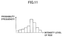
- the non-parametric method utilizes an observation frequency histogram of the intensity levels of the RSSIs, instead of utilizing the average and the covariance of the parameters of the location model.
- the value of the RSSI changes because the radio waves are reflected or blocked by surrounding walls, obstructions, or the like. For this reason, it is difficult to accurately represent the RSSI distribution by the parameters of the location model, such as the simple average and the covariance.
- a more accurate location model can be generated by utilizing the observation frequency histogram of the intensity levels of the RSSIs as the probability distribution. More particularly, when estimating the location of the mobile terminal, the observation probability of the newly observed RSSI feature vector is computed based on an RSSI intensity histogram, and the location where the observation probability becomes a maximum is output as the estimated location.
- the observation probability of the newly observed RSSI feature vector must be computed for all location models. For this reason, in a case in which the number of candidate locations is large, it takes a long time to perform the computing process. In addition, it is difficult to perform the on-line updating of the location model. Further, because the location estimation is a relative evaluation of the probability (that is, the location having the maximum probability is output), it is impossible to cope with a case in which the mobile terminal is at a location other than the learned location.
- the pattern matching method performs a more accurate modeling of the RSSI distribution, by utilizing a location model that is more complex compared to that utilized by the probability method described above.
- the pattern matching method includes the ANN (Artificial Neural Network), the SVM (Support Vector Machine), the GP (Gaussian Process), or the like, for example.
- the observed RSSI feature vector must be collated with a large number of location models, thereby taking a long time to perform the computing process and increasing the computation cost.
- relearning of the location model is required in a case in which the AP is newly set up, the AP is removed, the AP is moved, the layout of the furniture within the location changes, or the like.
- the conventional position estimating methods it takes a long time to perform the process and a high-speed estimation of the location is difficult, in a case in which the location of the mobile terminal is to be estimated from a large number of candidate locations on the order of several ten-thousand or more, for example.
- a mobile terminal communicable with a plurality of base stations and including a narrowing-down means for narrowing down candidate positions of the mobile terminal estimated from signals received from the plurality of base stations, based on missing data of the signals received from a certain base station; and an estimating means for estimating a position of the mobile terminal from the narrowed down candidate positions, based on an observation probability of intensities of the signals received.
- position estimating method position estimating system, and program, it is possible to estimate a location of a mobile terminal at a high speed.
- the disclosed terminal apparatus, position estimating method, position estimating system, program, and computer-readable storage medium may narrow down candidate positions of a mobile terminal estimated based on signals received from a plurality of base stations, based on missing data of the signal received from a certain base station, and estimate the position of the mobile terminal from the narrowed down candidate positions based on an observation probability of intensities of the signals received.
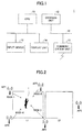
- FIG. 1 is a block diagram illustrating an example of a configuration of a mobile terminal in one embodiment.
- a mobile terminal 1 illustrated in FIG. 1 is an example of a terminal apparatus having a communicating function, and may be a mobile phone, or the like, for example.
- the mobile terminal 1 has a configuration in which a CPU (Central Processing Unit) 11, a storage unit 12, an input device 13, a display unit 14, and a communication unit 15 are connected via a bus 16, however, the configuration is not limited to a connection using the bus 16.
- a CPU Central Processing Unit
- the CPU 11 is an example of a computer or a processor.
- the CPU 11 controls the entire mobile terminal 1, and performs a position estimating process or the like, which will be described later, by executing a program.
- the storage unit 12 stores programs to be executed by the CPU 11, intermediate results of computations performed by the CPU 11, data used by the programs or computations executed by the CPU 11, or the like.
- the storage unit 12 may be formed by a computer-readable storage medium.
- the computer-readable storage medium may be a semiconductor memory device.
- the storage unit 12 may be formed by a reader and writer that reads information from and writes information to the recording medium that is loaded thereto.
- the input device 13 may be formed by a keyboard, or the like, and is operated when inputting commands, data, or the like to the mobile terminal 1, for example.
- the display unit 14 may be formed by an LCD (Liquid Crystal Display), for example, and displays guidances, messages, or the like.
- the input device 13 and the display unit 14 may be integrally provided, and may be formed by a touchscreen panel, for example.
- the communication unit 15 includes a radio communication function capable of making radio communication with an external apparatus (not illustrated), and has a known configuration including a receiver, a transmitter, an antenna, or the like.
- the communication unit 15 is communicable with an AP (Access Point) that uses Wi-Fi, for example.
- the AP is an example of a base station.
- FIG. 2 is a diagram for explaining an example of a relationship of a plurality of APs and locations where the mobile terminal may exist.
- a plurality of AP1 through AP5 cover locations L1 and L2, and the mobile terminal 1 carried by a user exists within the location L1.
- An RSSI (Received Signal Strength Indicator) at the mobile terminal 1 is RSSI-1 from the AP1, RSSI-2 from the AP2, RSSI-3 from the AP3, RSSI-4 from the AP4, and RSSI-5 from the AP5.
- RSSI Receiveived Signal Strength Indicator
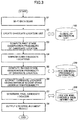
- FIG. 3 is a flow chart for explaining an example of a position estimating process of the mobile terminal.
- the position estimating process illustrated in FIG. 3 may be performed by the CPU 11.
- Wi-Fi data hereinafter also referred to as "Wi-Fi scan data”
- MAC Media Access Control
- step S1 a reference is made to a global AP information list 100 stored in the storage unit 12, in order to exclude an unlearned AP not included in the global AP list 100.
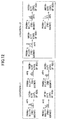
- FIG. 4 is a diagram illustrating an example of a data structure of the global AP information list.
- the global AP information list 100 illustrated in FIG. 4 includes, with respect to AP numbers 1, 2, ... allocated for each of the APs for the sake of convenience, MAC addresses M1, M2, ... of each of the APs and a coverage location list of each of the APs.
- the coverage location list of the AP stores the location names L1, L2, L3, ... or the like.
- the global AP information list 100 can be created based on information acquired from the Wi-Fi scan data. First, a blank global AP information list 100 is prepared. Thereafter, the global AP information list 100 is retrieved, and if a source AP (or check-in AP) of the Wi-Fi scan data is new, the MAC address of the check-in AP is added to the global AP information list 100. At the same time, the location name where the check-in is made is added to the coverage location list of the check-in AP.
- the coverage location list of this check-in AP is retrieved, and the check-in location name is added to the coverage location list if the check-in location name is new.
- step S2 a reference is made to the global AP information list 100 illustrated in FIG. 4 , and all coverage locations of the retrieved APs are regarded as candidate locations, so as to create a candidate location list and store the candidate location list in the storage unit 12.
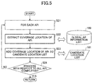
- FIG. 5 is a flow chart for explaining an example of a candidate location list creating process of step S2.
- step S21 illustrated in FIG. 5 processes of step S22 and subsequent steps are performed with respect to each APi.
- step S22 a reference is made to the global AP information list 100 illustrated in FIG. 4 , and the coverage location list of the APi is extracted.
- step S23 a process is performed to add all location members of the coverage location list of the APi to a candidate location list 101. However, step S23 is skipped when the location members are already added to the candidate location list 101.
- step S24 a judgment is performed to determine whether the process with respect to all APi is completed. The process returns to step S21 when the judgment result in step S24 is NO, and the process advances to step S3 illustrated in FIG. 3 when the judgment result in step S24 is YES.
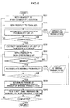
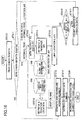
- FIG. 6 is a flow chart for explaining an example of a first stage observation probability computing process of step S3.
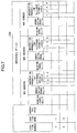
- FIG. 7 is a diagram illustrating an example of a data structure of a location model.
- a location model 200 illustrated in FIG. 7 stores a location number, a location name, a threshold value of a second stage observation probability used within the location, and an observable AP list.
- the observable AP list includes, with respect to the MAC address, a missing probability, an observation probability, an observation probability for different intensity levels of RSSIs when the AP is observed, or the like.
- FIG. 7 illustrates a case in which the number of intensity levels of the RSSIs when the AP is observed is 4, for example, and a length of the observable AP list is 3, for example.
- a location model 200 is stored in the storage unit 12, for example. Because the observable AP list includes a probability information part of the location model 200, FIG. 3 illustrates the location model 200 as a "location model (probability information)". On the other hand, parts other than the observable AP list include a threshold value information part of the second stage observation probability used at each location of the location model 200, FIG. 3 illustrates the location model 200 as a "location model (threshold value)".
- step S31 illustrated in FIG. 6 processes of step S32 and subsequent steps are performed with respect to each candidate location.
- steps S32 processes of step S33 and subsequent steps are performed with respect to each APi.
- step S34 the observable AP list of the candidate location of the location model 200 illustrated in FIG. 7 is retrieved, and if APi exists in this observable AP list, an observation probability that is learned in advance is acquired. On the other hand, if APi does not exist in the observable AP list, a relatively small constant, for example, that is set in advance, is regarded as the observation probability.
- step S34 the observation probability of APi is accumulated to a product of the observation probabilities stored in the storage unit 12.
- step S34 a judgment is made to determine whether the process with respect to all APi is completed. The process returns to step S32 when the judgment result in step S34 is NO, and the process advances to step S35 when the judgment result in step S34 is YES.
- step S35 the observable AP list of the candidate location of the location model 200 illustrated in FIG. 7 is extracted.
- step S36 processes of step S37 and subsequent steps are performed with respect to each observable AP.
- step S37 Wi-Fi scan data (AP1(MAC, RSSI), ...) are retrieved, and a judgment is made to determine whether an observable AP is missing.
- the MAC address of the observable AP does not exist within the Wi-Fi scan data, it is judged that the observable AP is missing and the judgment result in step S37 becomes NO, and the process returns to step S36.
- step S38 a missing probability of the observable AP is extracted from the location model 200, and the missing probability is accumulated to a product of the missing probabilities stored in the storage unit 12.
- step S39 a judgment is made to determine whether the process with respect to all observable APs is completed, and the process returns to step S36 when the judgment result in step S39 is NO.
- step S391 a product value of the product of the observation probabilities and the product of the missing probabilities stored in the storage unit 12 is computed.
- step S392 the product value computed in step S391 is regarded as a first stage observation probability of the candidate location, and is paired with the candidate location and stored in the storage unit 12.
- step S393 a judgment is made to determine whether the process with respect to all candidate locations is completed. The process returns to step S31 when the judgment result in step S393 is NO, and the process advances to step S4 illustrated in FIG. 3 when the judgment result in step S393 is YES.
- step S4 illustrated FIG. 3 the candidate locations having low first stage observation probabilities are discarded, in order to narrow down the candidate locations.
- step S5 a second stage observation probability is computed based on the RSSI feature vector, with respect to the narrowed down candidate locations.
- FIG. 8 is a flow chart for explaining an example of a second stage observation probability computing process of step S5.
- the second stage observation probability computing process illustrated in FIG. 8 is performed with respect to the candidate location lists that are narrowed down in step S4 according to the first stage observation probability computed in step S3.
- step S51 process of step S52 and subsequent steps are performed with respect to each candidate location.
- step S52 processes of step S53 and subsequent steps are performed with respect to each APi.
- step S53 a reference is made to the location model 200, and if the MAC address of APi exists in the observable AP list of the candidate location, an intensity level is computed from the RSSI of APi, and an observation probability for different intensity levels of the RSSIs when APi is observed is acquired from the location model 200.
- a relatively small fixed value for example, that is set in advance, is regarded as the observation probability for the different intensity levels of the RSSIs when APi is observed.
- step S54 the observation probability for the different intensity levels of the RSSIs when APi is observed is accumulated to a product of the observation probability for the different intensity levels stored in the storage unit 12.
- step S55 a judgment is made to determine whether the process with respect to all APi is completed. The process returns to step S52 when the judgment result in step S55 is NO, and the process advances to step S56 when the judgment result in step S55 is YES.
- step S56 a product value of the product of the missing probabilities computed in step S3 and a product of the observation probabilities for the different intensity levels stored in the storage unit 12 is computed, and the computed product value is stored in the storage unit 12.
- step S57 the product value computed in step S56 is regarded as a second stage observation probability of the candidate location, and is paired with the candidate location and stored in the storage unit 12.
- step S58 a judgment is made to determine whether the process with respect to all candidate locations is completed. The process returns to step S51 when the judgment result in step S58 is NO, and the process advances to step S6 illustrated in FIG. 3 when the judgment result in step S58 is YES.
- step S6 illustrated in FIG. 6 the candidate location having a maximum second stage observation probability is extracted (or selected).
- step S7 a reference is made to the location model 200 illustrated in FIG. 7 , and uses a threshold value of the candidate location having the maximum second stage observation probability, to judge that the mobile terminal 1 is not at a final candidate location and the location of the mobile terminal 1 is unknown in a case in which the second stage observation probability is less than the threshold value, and to judge that the mobile terminal 1 is at the final candidate location in a case in which the second stage observation probability is greater than or equal to the threshold value.
- step S8 a judgment result indicating the location of the mobile terminal 1, or indicating that the location of the mobile terminal 1 is unknown, is output, and the position estimating process ends.
- the judgment result output in step S8 may be output to an application or the like that provides services utilizing the position of the mobile terminal 1, for example.
- the CPU 11 may perform the processes (or procedures) of steps S1 through S5 to function as a narrowing-down means for narrowing down the candidate positions of the mobile terminal estimated from the signals received from the plurality of base station, based on the missing data of the signals received from a certain base station.
- the CPU 11 may perform the processes (or procedures) of steps S6 and S7 to function as an estimating means for estimating the position of the mobile terminal from the narrowed down candidate positions based on the observation probability of intensities of the signals received.
- the candidate location list 101 is gradually narrowed down to finally narrow down the candidate locations to a single candidate location. With respect to this final candidate location, a judgment is made to determine whether the mobile terminal 1 is positively located at this final candidate location.
- the observation probability of the RSSI feature vectors are computed based on relatively coarse information.
- the candidate location list 101 is created from the global AP information list 100 that is observed, and the AP observation probability and the missing probability within the location model 200 are utilized to compute the first stage observation probability.
- the location probability can be computed using only information related to 2 AP states that are missing and observation, and a first narrowing-down is performed on the candidate location list 101 based on the computed location probability, in order to estimate the locations where the mobile terminal 1 is likely to exist.
- FIG. 10 is a diagram illustrating an example of the AP states at the plurality of locations. In FIG. 10 , it is assumed for the sake of convenience that AP1 through AP5 are arranged at the same positions as in FIG. 2 .
- FIG. 9 is a diagram illustrating an example of a relationship of the probabilities of AP states and the AP states at the locations L1 and L2 illustrated in FIG. 10 .
- a stage probability (first stage observation probability) p for a case in which the Wi-Fi scan data from AP1, AP3, and AP5 are observed, for example, becomes as follows.
- location L ⁇ 1 p AP ⁇ 2 missing
- location L ⁇ 1 p AP ⁇ 3 observed
- location L ⁇ 1 p AP ⁇ 4 missing
- location L ⁇ 1 p AP ⁇ 5 observed
- location L ⁇ 2 p AP ⁇ 2 missing
- location L ⁇ 2 p AP ⁇ 3 observed
- location L ⁇ 2 p AP ⁇ 4 missing
- location L ⁇ 2 p AP ⁇ 5 observed
- the second stage observation probability is computed based on the observation probability of the intensity level of the RSSI and the AP missing probability, with respect to the candidate locations having first stage observation probabilities higher than a predetermined value.
- the location probability is computed based on the observation probability of the intensity level of the RSSI of the candidate locations illustrated in FIG. 11 , for example, and the AP missing probability, with respect to the narrowed down locations where the mobile terminal 1 is likely to exist.
- a second narrowing-down is performed on the candidate location list 101 based on the computed location probability, in order to narrow down the locations to the location candidates having the location probability that is greater than or equal to a certain value and relatively large.
- FIG. 12 is a diagram illustrating an example of the intensity level of the RSSI at the plurality of locations. In FIG. 12 , it is assumed for the sake of convenience that AP1 through AP5 are arranged at the same positions as in FIG. 2 .
- FIG. 11 is a diagram illustrating an example of a relationship of the AP missing probability and the intensity level of the RSSI at the locations L1 and L2 illustrated in FIG. 12 .
- a stage probability (second stage observation probability) p for a case in which the Wi-Fi scan data from AP1, AP3, and AP5 are observed becomes as follows, where the intensity levels of the RSSIs from AP1, AP3, and AP5 are denoted by E, C, and F, respectively.
- a judgment is made with respect to the candidate location having the maximum second stage observation probability, to finally determine whether the mobile terminal 1 is located at the candidate location having the maximum second stage observation probability.
- the second stage observation probability of the final candidate location that is narrowed down by the second narrowing-down is compared with a learned threshold value. It is judged that the mobile terminal 1 is located at the final candidate location when the second stage observation probability is greater than or equal to the threshold value, and it is judged that the location of the mobile terminal 1 is unknown when the second stage observation probability is less than the threshold value.
- the learned threshold value is computed from an average and a standard deviation of the location probabilities computed based on the AP missing probability and the probability distribution of the intensity levels of the RSSIs.
- the candidate location list 101 is subjected to the first narrowing-down and the second narrowing-down, and is finally narrowed down to the candidate location having the maximum second stage observation probability.
- FIG. 14 is a diagram for explaining an example of an operation of the position estimating system in one embodiment.
- a position estimating system 20 illustrated in FIG. 14 includes a mobile terminal 1, and a server 21 that is wirelessly communicable with the mobile terminal 1.
- the server 21 can learn a location model 200 using data (hereinafter also referred to as "check-in data") checked in from the mobile terminal 1.
- the mobile terminal 1 performs a position estimating process based on a newly observed RSSI feature vector, according to the location model 200 downloaded from the server 21.
- the server 21 may have a known configuration including a processor and a storage unit, similar to the configuration of the mobile terminal 1 illustrated in FIG. 1 , for example, and thus, illustration and description of the configuration of the server 21 will be omitted.
- step ST1 illustrated in FIG. 14 the mobile terminal 1 acquires the check-in data by acquiring the MAC address and the RSSI of each AP from the Wi-Fi scan data.
- step ST2 the mobile terminal 1 transmits the check-in data to the server 21.
- step ST21 the server 21 receives the check-in data from the mobile terminal 1 and stores the check-in data in a check-in data file 300 within a storage unit of the server 21.
- step ST22 the server 21 reads the check-in data file 300 from the storage unit of the server 21, and performs a learning process to learn the location model 200.
- the learning process to learn the location model 200 includes 2 learning stages, namely, a learning of a probability information part of the location model 200, and a learning of a threshold value information part of the location model 200.
- the learning of the probability information part uses the check-in data to learn the location model (probability information) that is the probability information part of the location model 200. Thereafter, in the calculation of the second stage observation probability, the second stage of the location estimating process is performed with respect to the check-in data based on the location model (probability information).
- the second stage observation probability and the location name of the check-in location obtained by the second stage of the location estimating process are used to compute the threshold value of the second stage observation probability, that is, the threshold value of each check-in location, to learn the location model (threshold value information) that is the threshold value information part of the location model 200.
- the learning of the location model 200 is completed after learning the probability information part and the threshold value information part of the location models.
- step ST23 the server 21 generates a file (hereinafter also referred to as a "location model file") 200A of the learned location model 200, and stores the location model file 200A in the storage unit of the server 21.
- step ST24 the server 21 reads the location model file 200A from the storage unit of the server 21, and transmits the location model file 200A to the mobile terminal 1.
- step ST3 the mobile terminal 1 receives the location model file 200A from the server 21, and stores the location model file 200A in the storage unit 12 of the mobile terminal 1. In other words, the mobile terminal 1 stores the location model file 200A in the storage unit 12 every time a new location model file 200A is generated in the server 21.
- step ST4 the mobile terminal 1 reads the location model file 200A from the storage unit 12, uses the location model 200 to perform the position estimating process based on the RSSI feature vector of the check-in data, and outputs a judgment result on the location of the mobile terminal 1.
- the learning process to learn the location model 200 includes the learning of the location model (probability information) and the location model (threshold value information).
- FIG. 15 is a diagram for explaining an example of the location model learning process performed by the server.
- the server 21 performs the learning process to learn the location model (probability information), to learn the probability information such as the AP missing probability, the AP observation probability, the observation probability for the different intensity levels of the RSSIs when the AP is observed, or the like, with respect to each observable AP at each location.
- the learned probability information is stored in the location model 200 within the storage unit of the server 21.
- the AP missing probability is a numerical value that is obtained by dividing a missing number of a target AP in all of the check-in data by a total number of check-in data.
- the missing number is a numerical value that is obtained by subtracting an observation number from the total number of check-in data.
- the AP observation probability is a numerical value that is obtained by dividing the observation number of the target AP of all of the check-in data by the total number of check-in data.
- the observation probability for the different intensity levels of the RSSIs when the AP is observed is a numerical value that is obtained by discretizing the RSSIs to the plurality of intensity levels at predetermined intervals, and thereafter dividing the observation number of each intensity level of the target AP by the total number of check-in data.
- the learning of the location model includes steps ST32 and ST33.
- step ST32 the server 21 computes the threshold value of the second stage observation probability for each location. More particularly, the second stage observation probability is computed based on the location model (probability information) that is learned as described above, with respect to all of the check-in data.
- step ST333 the server 21 computes the average and the standard deviation of the second stage observation probability, and computes the threshold value based on the average and the standard deviation of the computed second stage observation probability, according to the AP missing probability and the probability distribution of the intensity levels of the RSSIs.
- the learned threshold value information is stored in the location model 200 within the storage unit of the server 21.
- FIG. 16 is a flow chart for explaining an example of the location model (probability information) learning process of the server.
- step ST310 illustrated in FIG. 16 the check-in data is read from the check-in data file 30 within the storage unit of the server 21.
- step ST311 a judgment is made to determine whether new check-in data exist, and when the judgment result in step ST311 is YES, the process advances in parallel to steps ST312 and ST313. When the judgment result in step ST311 is NO, the process advances to step ST318 which will be described later.
- step ST311 When the new check-in data exist and the judgment result in step ST311 is YES, the check-in data (AP1(MAC, RSSI), ..., APi(MAC, RSSI), ...: location A) within a frame indicated by dotted lines are supplied to steps ST312 and ST313.
- step ST312 a new check-in location name (location A) is registered in the location model 200 illustrated in FIG. 7 .
- the check-in location (location A) is a new location, a new location number is allocated to this new location, and a new row is added to the location model 200 illustrated in FIG. 7 .
- step ST313 processes of step ST314 and subsequent steps are performed with respect to each APi.
- step ST314 the check-in AP is registered to the global AP information list 100 illustrated in FIG. 4 .
- the new AP for example APi
- a new AP number is allocated to this new AP, and a new row is added to the global AP information list 100 illustrated in FIG. 4 .
- step ST315 a process is performed to link information of the check-in location name and the check-in AP.
- FIG. 17 is a flow chart for explaining an example of a location and an AP i linking process of step ST315.
- step ST3151 illustrated in FIG. 17 the check-in location A is registered to an AP covering location list of the global AP information list 100 illustrated in FIG. 4 .
- step ST3152 the check-in AP is registered to the observable AP list of the location model 200 illustrated in FIG. 7 .
- step ST3153 an observation number of the APi is incremented (or counted), and in step ST3154, the observation number for the different intensity levels of the RSSIs of the APi is incremented (or counted), and the process advances to step ST316 illustrated in FIG. 16 .
- step ST316 a judgment is made to determine whether the process with respect to all APi is completed.
- the process returns to ST313 when the judgment result in step ST316 is NO, and the process advances to step ST317 when the judgment result in step ST316 is YES.
- step ST317 the number of check-in data is counted, and the process returns to step ST311.
- step ST318 the location at each location number of the location model 200 illustrated in FIG. 7 is scanned to compute the missing number of each AP, and the missing number is divided by the number of check-in data and normalized.
- step ST319 the observation number of each AP is divided by the number of check-in data and normalized.
- step ST320 the observation number of the intensity level of the RSSI of each AP is divided by the number of check-in data and normalized, and the process ends.
- FIG. 18 is a flow chart for explaining an example of a location model (threshold information) learning process of the server.
- step ST331 illustrated in FIG. 18 the check-in data is read from the check-in data file 300 within the storage unit of the server 21.
- step ST332 a judgment is made to determine whether new check-in data exist, and when the judgment result in step ST332 is YES, the process advances to step ST333. When the judgment result in step ST332 is NO, the process advances to step ST335 which will be described later.
- step ST332 When the new check-in data exist and the judgment result in step ST332 is YES, the check-in data (AP1(MAC, RSSI), ..., APi(MAC, RSSI), ...: location A) within a frame indicated by dotted lines are supplied to step ST333.
- step ST333 the second stage observation probability of the check-in data is computed by the above described method, based on the location model (probability information) and the global AP information list 100.
- the process returns to step ST331 on one hand to scan new check-in data, and the process advances in parallel to step ST334 on the other to store the store the second stage observation probability computed in step ST333 in the storage unit of the server 21 for each check-in location.
- step ST335 after completing the process of step ST333 for all of the check-in data, the average and the standard deviation of the second stage observation probabilities are computed for each check-in location.
- step ST336 the threshold value is computed for each location based on the average and the standard deviation computed in step ST335, to store the computed threshold value in the location model (threshold value information), and the process ends.
- the increased location can be learned and added to the location model, thereby eliminating a need to relearn the learned locations.
- the location model on the server side can be updated based on the check-in data checked in from the mobile terminal side.
- the radio waves from a certain AP may no longer be receivable.
- the missing data is generated in the signals received from the certain AP, that is, in the RSSI observation vector, and a missing value is generated in the RSSI feature vector in such a case.
- the conventional method of creating the location model does not cope with the missing value in the RSSI feature vector, or takes insufficient measures to cope with the missing value in the RSSI feature vector, and for this reason, it is difficult to improve the location estimating accuracy.
- the missing value within the RSSI feature vector is ignored, and the missing probability is not reflected to the computation of the observation probability of the RSSI feature vectors. For this reason, the location estimating accuracy deteriorates in the case in which the missing value is generated.
- the missing value within the RSSI feature vector is generally substituted by a constant, an interpolation value based on past RSSI data, or the like.
- a value that is substituted for the missing value greatly affects the computation of the distance between the RSSI observation vector and the sample of the database, and it is difficult to set the value that is substituted to an appropriate value. For this reason, in a case in which the missing value is generated, the location estimating accuracy deteriorates unless an appropriate value is substituted for the missing value.
- the location can be estimated more accurately by utilizing the missing information of the AP, and the location can be estimated at a high speed by performing the 2-stage observation probability computation.
- the learned threshold value for each location it is possible, for example, to output a judgment result indicating that the location of the mobile terminal is unknown.
Landscapes
- Engineering & Computer Science (AREA)
- Physics & Mathematics (AREA)
- General Physics & Mathematics (AREA)
- Radar, Positioning & Navigation (AREA)
- Remote Sensing (AREA)
- Computer Networks & Wireless Communication (AREA)
- Signal Processing (AREA)
- Probability & Statistics with Applications (AREA)
- Position Fixing By Use Of Radio Waves (AREA)
- Mobile Radio Communication Systems (AREA)
Applications Claiming Priority (1)
| Application Number | Priority Date | Filing Date | Title |
|---|---|---|---|
| PCT/JP2013/059237 WO2014155602A1 (fr) | 2013-03-28 | 2013-03-28 | Dispositif terminal, procédé d'estimation de position, système d'estimation de position, et programme |
Publications (3)
| Publication Number | Publication Date |
|---|---|
| EP2981136A1 true EP2981136A1 (fr) | 2016-02-03 |
| EP2981136A4 EP2981136A4 (fr) | 2016-04-13 |
| EP2981136B1 EP2981136B1 (fr) | 2018-10-24 |
Family
ID=51622677
Family Applications (1)
| Application Number | Title | Priority Date | Filing Date |
|---|---|---|---|
| EP13880249.1A Active EP2981136B1 (fr) | 2013-03-28 | 2013-03-28 | Dispositif terminal, procédé d'estimation de position, système d'estimation de position, et programme |
Country Status (4)
| Country | Link |
|---|---|
| US (1) | US9503855B2 (fr) |
| EP (1) | EP2981136B1 (fr) |
| JP (1) | JP6086148B2 (fr) |
| WO (1) | WO2014155602A1 (fr) |
Cited By (1)
| Publication number | Priority date | Publication date | Assignee | Title |
|---|---|---|---|---|
| JP6300216B1 (ja) * | 2017-05-01 | 2018-03-28 | タメコ株式会社 | 位置特定方法、位置特定装置およびプログラム |
Families Citing this family (15)
| Publication number | Priority date | Publication date | Assignee | Title |
|---|---|---|---|---|
| JP6241177B2 (ja) * | 2013-09-27 | 2017-12-06 | 富士通株式会社 | 場所モデル更新装置、位置推定方法及びプログラム |
| JP6221573B2 (ja) * | 2013-09-27 | 2017-11-01 | 富士通株式会社 | 場所モデル更新装置、位置推定方法及びプログラム |
| WO2015156058A1 (fr) * | 2014-04-08 | 2015-10-15 | 株式会社日立国際電気 | Dispositif de réception |
| KR101676571B1 (ko) * | 2015-06-26 | 2016-11-15 | 네이버비즈니스플랫폼 주식회사 | 실내 측위 서비스 제공 방법 및 시스템 |
| US10481239B2 (en) * | 2015-12-31 | 2019-11-19 | Robert Bosch Gmbh | Indoor room-localization system and method therof |
| JP6908970B2 (ja) * | 2016-03-24 | 2021-07-28 | キヤノン株式会社 | 通信装置とその制御方法及びプログラム |
| JP6759757B2 (ja) * | 2016-06-24 | 2020-09-23 | トヨタ自動車株式会社 | 移動体の位置推定装置 |
| KR102601052B1 (ko) | 2017-02-23 | 2023-11-09 | 매직 립, 인코포레이티드 | 가변 파워 반사기를 갖는 디스플레이 시스템 |
| KR20190034985A (ko) | 2017-09-25 | 2019-04-03 | 삼성전자주식회사 | 인공 신경망의 양자화 방법 및 장치 |
| CN108093423A (zh) * | 2017-12-18 | 2018-05-29 | 北京工业大学 | 一种基于Ransac算法的用户话单大数据中基站位置异常的发现方法 |
| US11403543B2 (en) | 2018-12-03 | 2022-08-02 | Cognitive Systems Corp. | Determining a location of motion detected from wireless signals |
| US10506384B1 (en) * | 2018-12-03 | 2019-12-10 | Cognitive Systems Corp. | Determining a location of motion detected from wireless signals based on prior probability |
| JP7310269B2 (ja) * | 2019-04-25 | 2023-07-19 | 住友電気工業株式会社 | 測位システム、測位処理装置、測位方法及びコンピュータプログラム |
| CN113567917A (zh) * | 2020-04-29 | 2021-10-29 | 南宁富桂精密工业有限公司 | 室内定位方法、电子装置及计算机可读储存媒体 |
| US11057118B2 (en) * | 2020-04-29 | 2021-07-06 | Intel Corporation | Indoor localization with beacon technology based on signal strength distribution and deep learning techniques |
Family Cites Families (7)
| Publication number | Priority date | Publication date | Assignee | Title |
|---|---|---|---|---|
| US6748324B2 (en) * | 2002-01-07 | 2004-06-08 | Motorola, Inc. | Method for determining location information |
| US7242950B2 (en) * | 2003-02-18 | 2007-07-10 | Sbc Properties, L.P. | Location determination using historical data |
| US7738884B2 (en) * | 2005-06-28 | 2010-06-15 | Microsoft Corporation | Positioning service utilizing existing radio base stations |
| IE20100162A1 (en) * | 2009-03-19 | 2010-09-29 | Cork Inst Technology | A location and tracking system |
| JP5240691B2 (ja) | 2009-03-31 | 2013-07-17 | 株式会社国際電気通信基礎技術研究所 | 所有者識別システム |
| FR2946825B1 (fr) * | 2009-06-12 | 2011-08-05 | Univ Paris Curie | Geolocalisation d'une station mobile d'un reseau de telephonie sans fil |
| JP2011179946A (ja) | 2010-03-01 | 2011-09-15 | Doshisha | 位置推定方法および位置推定システム |
-
2013
- 2013-03-28 WO PCT/JP2013/059237 patent/WO2014155602A1/fr active Application Filing
- 2013-03-28 EP EP13880249.1A patent/EP2981136B1/fr active Active
- 2013-03-28 JP JP2015507800A patent/JP6086148B2/ja active Active
-
2015
- 2015-08-19 US US14/830,012 patent/US9503855B2/en active Active
Cited By (2)
| Publication number | Priority date | Publication date | Assignee | Title |
|---|---|---|---|---|
| JP6300216B1 (ja) * | 2017-05-01 | 2018-03-28 | タメコ株式会社 | 位置特定方法、位置特定装置およびプログラム |
| JP2018189467A (ja) * | 2017-05-01 | 2018-11-29 | タメコ株式会社 | 位置特定方法、位置特定装置およびプログラム |
Also Published As
| Publication number | Publication date |
|---|---|
| JPWO2014155602A1 (ja) | 2017-02-16 |
| US9503855B2 (en) | 2016-11-22 |
| US20150358781A1 (en) | 2015-12-10 |
| WO2014155602A1 (fr) | 2014-10-02 |
| EP2981136A4 (fr) | 2016-04-13 |
| EP2981136B1 (fr) | 2018-10-24 |
| JP6086148B2 (ja) | 2017-03-01 |
Similar Documents
| Publication | Publication Date | Title |
|---|---|---|
| EP2981136B1 (fr) | Dispositif terminal, procédé d'estimation de position, système d'estimation de position, et programme | |
| US9226262B2 (en) | Location model updating apparatus and position estimating method | |
| KR101625757B1 (ko) | 무선랜 라디오맵 자동 구축 방법 및 시스템 | |
| US9253750B2 (en) | Location model updating apparatus and location estimating method | |
| CN104883734A (zh) | 一种基于地理指纹的室内被动定位方法 | |
| CN108983204B (zh) | 一种无钥匙进入和无钥匙启动系统定位方法 | |
| US20230388812A1 (en) | Learning method, wireless quality estimation method, learning device, wireless quality estimation device, and program | |
| CN111698695A (zh) | 一种基于神经网络的lte指纹式定位方法 | |
| Lee et al. | Developing an improved fingerprint positioning radio map using the k-means clustering algorithm | |
| CN109121081B (zh) | 一种基于位置候选集与em算法的室内定位方法 | |
| Liu et al. | Performance analysis of adaptive K for weighted K-nearest neighbor based indoor positioning | |
| CN108919182B (zh) | 一种wifi环境下基于支撑集及期望最大化的目标定位方法 | |
| JP2017118384A (ja) | 管理装置、コンピュータに実行させるためのプログラムおよびそのプログラムを記録したコンピュータ読み取り可能な記録媒体 | |
| Alfakih et al. | An enhanced indoor positioning method based on Wi-fi RSS fingerprinting | |
| EP4266004A1 (fr) | Procédé de positionnement de trajectoire d'utilisateur, dispositif électronique et support de stockage informatique | |
| JP7235931B2 (ja) | 予測モデル作成装置、予測モデル作成方法及びプログラム | |
| US11408964B2 (en) | Location estimating apparatus, location estimating method and program storing recording medium, and location estimating system | |
| Li et al. | Performance Comparison and Evaluation of Indoor Positioning Technology Based on Machine Learning Algorithms | |
| EP4068812B1 (fr) | Méthode, dispositif et logiciel d'ordinateur de la classification d'interférence améliorée et géolocalisation utilisant la trajectoire d'un véhicule mobile | |
| CN112423333B (zh) | 基于位置指纹匹配的蜂窝网络无线定位方法 | |
| JPH1075218A (ja) | データ群の特性境界識別方法及び装置 | |
| Zhou et al. | An iterative scheme for feature based positioning using a weighted dissimilarity measure | |
| JP4060110B2 (ja) | 方探データ分類装置及び方探データ分類プログラム | |
| Del Mundo et al. | Hybrid classifier for Wi-Fi fingerprinting system | |
| Xu et al. | Research on Digital Key Positioning Method Based on Bluetooth Low Energy |
Legal Events
| Date | Code | Title | Description |
|---|---|---|---|
| PUAI | Public reference made under article 153(3) epc to a published international application that has entered the european phase |
Free format text: ORIGINAL CODE: 0009012 |
|
| 17P | Request for examination filed |
Effective date: 20150812 |
|
| AK | Designated contracting states |
Kind code of ref document: A1 Designated state(s): AL AT BE BG CH CY CZ DE DK EE ES FI FR GB GR HR HU IE IS IT LI LT LU LV MC MK MT NL NO PL PT RO RS SE SI SK SM TR |
|
| AX | Request for extension of the european patent |
Extension state: BA ME |
|
| A4 | Supplementary search report drawn up and despatched |
Effective date: 20160316 |
|
| RIC1 | Information provided on ipc code assigned before grant |
Ipc: G01S 5/02 20060101ALI20160310BHEP Ipc: H04W 64/00 20090101AFI20160310BHEP |
|
| DAX | Request for extension of the european patent (deleted) | ||
| GRAP | Despatch of communication of intention to grant a patent |
Free format text: ORIGINAL CODE: EPIDOSNIGR1 |
|
| STAA | Information on the status of an ep patent application or granted ep patent |
Free format text: STATUS: GRANT OF PATENT IS INTENDED |
|
| INTG | Intention to grant announced |
Effective date: 20180606 |
|
| GRAS | Grant fee paid |
Free format text: ORIGINAL CODE: EPIDOSNIGR3 |
|
| GRAA | (expected) grant |
Free format text: ORIGINAL CODE: 0009210 |
|
| STAA | Information on the status of an ep patent application or granted ep patent |
Free format text: STATUS: THE PATENT HAS BEEN GRANTED |
|
| AK | Designated contracting states |
Kind code of ref document: B1 Designated state(s): AL AT BE BG CH CY CZ DE DK EE ES FI FR GB GR HR HU IE IS IT LI LT LU LV MC MK MT NL NO PL PT RO RS SE SI SK SM TR |
|
| REG | Reference to a national code |
Ref country code: CH Ref legal event code: EP |
|
| REG | Reference to a national code |
Ref country code: IE Ref legal event code: FG4D |
|
| REG | Reference to a national code |
Ref country code: AT Ref legal event code: REF Ref document number: 1058196 Country of ref document: AT Kind code of ref document: T Effective date: 20181115 |
|
| REG | Reference to a national code |
Ref country code: DE Ref legal event code: R096 Ref document number: 602013045761 Country of ref document: DE |
|
| REG | Reference to a national code |
Ref country code: NL Ref legal event code: MP Effective date: 20181024 |
|
| REG | Reference to a national code |
Ref country code: LT Ref legal event code: MG4D |
|
| REG | Reference to a national code |
Ref country code: AT Ref legal event code: MK05 Ref document number: 1058196 Country of ref document: AT Kind code of ref document: T Effective date: 20181024 |
|
| PG25 | Lapsed in a contracting state [announced via postgrant information from national office to epo] |
Ref country code: NL Free format text: LAPSE BECAUSE OF FAILURE TO SUBMIT A TRANSLATION OF THE DESCRIPTION OR TO PAY THE FEE WITHIN THE PRESCRIBED TIME-LIMIT Effective date: 20181024 |
|
| PG25 | Lapsed in a contracting state [announced via postgrant information from national office to epo] |
Ref country code: PL Free format text: LAPSE BECAUSE OF FAILURE TO SUBMIT A TRANSLATION OF THE DESCRIPTION OR TO PAY THE FEE WITHIN THE PRESCRIBED TIME-LIMIT Effective date: 20181024 Ref country code: NO Free format text: LAPSE BECAUSE OF FAILURE TO SUBMIT A TRANSLATION OF THE DESCRIPTION OR TO PAY THE FEE WITHIN THE PRESCRIBED TIME-LIMIT Effective date: 20190124 Ref country code: BG Free format text: LAPSE BECAUSE OF FAILURE TO SUBMIT A TRANSLATION OF THE DESCRIPTION OR TO PAY THE FEE WITHIN THE PRESCRIBED TIME-LIMIT Effective date: 20190124 Ref country code: HR Free format text: LAPSE BECAUSE OF FAILURE TO SUBMIT A TRANSLATION OF THE DESCRIPTION OR TO PAY THE FEE WITHIN THE PRESCRIBED TIME-LIMIT Effective date: 20181024 Ref country code: AT Free format text: LAPSE BECAUSE OF FAILURE TO SUBMIT A TRANSLATION OF THE DESCRIPTION OR TO PAY THE FEE WITHIN THE PRESCRIBED TIME-LIMIT Effective date: 20181024 Ref country code: IS Free format text: LAPSE BECAUSE OF FAILURE TO SUBMIT A TRANSLATION OF THE DESCRIPTION OR TO PAY THE FEE WITHIN THE PRESCRIBED TIME-LIMIT Effective date: 20190224 Ref country code: ES Free format text: LAPSE BECAUSE OF FAILURE TO SUBMIT A TRANSLATION OF THE DESCRIPTION OR TO PAY THE FEE WITHIN THE PRESCRIBED TIME-LIMIT Effective date: 20181024 Ref country code: LT Free format text: LAPSE BECAUSE OF FAILURE TO SUBMIT A TRANSLATION OF THE DESCRIPTION OR TO PAY THE FEE WITHIN THE PRESCRIBED TIME-LIMIT Effective date: 20181024 Ref country code: LV Free format text: LAPSE BECAUSE OF FAILURE TO SUBMIT A TRANSLATION OF THE DESCRIPTION OR TO PAY THE FEE WITHIN THE PRESCRIBED TIME-LIMIT Effective date: 20181024 Ref country code: FI Free format text: LAPSE BECAUSE OF FAILURE TO SUBMIT A TRANSLATION OF THE DESCRIPTION OR TO PAY THE FEE WITHIN THE PRESCRIBED TIME-LIMIT Effective date: 20181024 |
|
| PG25 | Lapsed in a contracting state [announced via postgrant information from national office to epo] |
Ref country code: RS Free format text: LAPSE BECAUSE OF FAILURE TO SUBMIT A TRANSLATION OF THE DESCRIPTION OR TO PAY THE FEE WITHIN THE PRESCRIBED TIME-LIMIT Effective date: 20181024 Ref country code: AL Free format text: LAPSE BECAUSE OF FAILURE TO SUBMIT A TRANSLATION OF THE DESCRIPTION OR TO PAY THE FEE WITHIN THE PRESCRIBED TIME-LIMIT Effective date: 20181024 Ref country code: SE Free format text: LAPSE BECAUSE OF FAILURE TO SUBMIT A TRANSLATION OF THE DESCRIPTION OR TO PAY THE FEE WITHIN THE PRESCRIBED TIME-LIMIT Effective date: 20181024 Ref country code: PT Free format text: LAPSE BECAUSE OF FAILURE TO SUBMIT A TRANSLATION OF THE DESCRIPTION OR TO PAY THE FEE WITHIN THE PRESCRIBED TIME-LIMIT Effective date: 20190224 Ref country code: GR Free format text: LAPSE BECAUSE OF FAILURE TO SUBMIT A TRANSLATION OF THE DESCRIPTION OR TO PAY THE FEE WITHIN THE PRESCRIBED TIME-LIMIT Effective date: 20190125 |
|
| REG | Reference to a national code |
Ref country code: DE Ref legal event code: R097 Ref document number: 602013045761 Country of ref document: DE |
|
| PG25 | Lapsed in a contracting state [announced via postgrant information from national office to epo] |
Ref country code: IT Free format text: LAPSE BECAUSE OF FAILURE TO SUBMIT A TRANSLATION OF THE DESCRIPTION OR TO PAY THE FEE WITHIN THE PRESCRIBED TIME-LIMIT Effective date: 20181024 Ref country code: DK Free format text: LAPSE BECAUSE OF FAILURE TO SUBMIT A TRANSLATION OF THE DESCRIPTION OR TO PAY THE FEE WITHIN THE PRESCRIBED TIME-LIMIT Effective date: 20181024 Ref country code: CZ Free format text: LAPSE BECAUSE OF FAILURE TO SUBMIT A TRANSLATION OF THE DESCRIPTION OR TO PAY THE FEE WITHIN THE PRESCRIBED TIME-LIMIT Effective date: 20181024 |
|
| PG25 | Lapsed in a contracting state [announced via postgrant information from national office to epo] |
Ref country code: RO Free format text: LAPSE BECAUSE OF FAILURE TO SUBMIT A TRANSLATION OF THE DESCRIPTION OR TO PAY THE FEE WITHIN THE PRESCRIBED TIME-LIMIT Effective date: 20181024 Ref country code: SM Free format text: LAPSE BECAUSE OF FAILURE TO SUBMIT A TRANSLATION OF THE DESCRIPTION OR TO PAY THE FEE WITHIN THE PRESCRIBED TIME-LIMIT Effective date: 20181024 Ref country code: EE Free format text: LAPSE BECAUSE OF FAILURE TO SUBMIT A TRANSLATION OF THE DESCRIPTION OR TO PAY THE FEE WITHIN THE PRESCRIBED TIME-LIMIT Effective date: 20181024 Ref country code: SK Free format text: LAPSE BECAUSE OF FAILURE TO SUBMIT A TRANSLATION OF THE DESCRIPTION OR TO PAY THE FEE WITHIN THE PRESCRIBED TIME-LIMIT Effective date: 20181024 |
|
| PLBE | No opposition filed within time limit |
Free format text: ORIGINAL CODE: 0009261 |
|
| STAA | Information on the status of an ep patent application or granted ep patent |
Free format text: STATUS: NO OPPOSITION FILED WITHIN TIME LIMIT |
|
| 26N | No opposition filed |
Effective date: 20190725 |
|
| PG25 | Lapsed in a contracting state [announced via postgrant information from national office to epo] |
Ref country code: SI Free format text: LAPSE BECAUSE OF FAILURE TO SUBMIT A TRANSLATION OF THE DESCRIPTION OR TO PAY THE FEE WITHIN THE PRESCRIBED TIME-LIMIT Effective date: 20181024 Ref country code: MC Free format text: LAPSE BECAUSE OF FAILURE TO SUBMIT A TRANSLATION OF THE DESCRIPTION OR TO PAY THE FEE WITHIN THE PRESCRIBED TIME-LIMIT Effective date: 20181024 |
|
| REG | Reference to a national code |
Ref country code: CH Ref legal event code: PL |
|
| PG25 | Lapsed in a contracting state [announced via postgrant information from national office to epo] |
Ref country code: LU Free format text: LAPSE BECAUSE OF NON-PAYMENT OF DUE FEES Effective date: 20190328 |
|
| REG | Reference to a national code |
Ref country code: BE Ref legal event code: MM Effective date: 20190331 |
|
| PG25 | Lapsed in a contracting state [announced via postgrant information from national office to epo] |
Ref country code: CH Free format text: LAPSE BECAUSE OF NON-PAYMENT OF DUE FEES Effective date: 20190331 Ref country code: LI Free format text: LAPSE BECAUSE OF NON-PAYMENT OF DUE FEES Effective date: 20190331 Ref country code: IE Free format text: LAPSE BECAUSE OF NON-PAYMENT OF DUE FEES Effective date: 20190328 |
|
| PG25 | Lapsed in a contracting state [announced via postgrant information from national office to epo] |
Ref country code: BE Free format text: LAPSE BECAUSE OF NON-PAYMENT OF DUE FEES Effective date: 20190331 |
|
| PG25 | Lapsed in a contracting state [announced via postgrant information from national office to epo] |
Ref country code: TR Free format text: LAPSE BECAUSE OF FAILURE TO SUBMIT A TRANSLATION OF THE DESCRIPTION OR TO PAY THE FEE WITHIN THE PRESCRIBED TIME-LIMIT Effective date: 20181024 |
|
| PG25 | Lapsed in a contracting state [announced via postgrant information from national office to epo] |
Ref country code: MT Free format text: LAPSE BECAUSE OF NON-PAYMENT OF DUE FEES Effective date: 20190328 |
|
| REG | Reference to a national code |
Ref country code: DE Ref legal event code: R082 Ref document number: 602013045761 Country of ref document: DE Representative=s name: HL KEMPNER PATENTANWAELTE, SOLICITORS (ENGLAND, DE Ref country code: DE Ref legal event code: R082 Ref document number: 602013045761 Country of ref document: DE Representative=s name: HL KEMPNER PATENTANWALT, RECHTSANWALT, SOLICIT, DE |
|
| PG25 | Lapsed in a contracting state [announced via postgrant information from national office to epo] |
Ref country code: CY Free format text: LAPSE BECAUSE OF FAILURE TO SUBMIT A TRANSLATION OF THE DESCRIPTION OR TO PAY THE FEE WITHIN THE PRESCRIBED TIME-LIMIT Effective date: 20181024 |
|
| PG25 | Lapsed in a contracting state [announced via postgrant information from national office to epo] |
Ref country code: HU Free format text: LAPSE BECAUSE OF FAILURE TO SUBMIT A TRANSLATION OF THE DESCRIPTION OR TO PAY THE FEE WITHIN THE PRESCRIBED TIME-LIMIT; INVALID AB INITIO Effective date: 20130328 |
|
| PG25 | Lapsed in a contracting state [announced via postgrant information from national office to epo] |
Ref country code: MK Free format text: LAPSE BECAUSE OF FAILURE TO SUBMIT A TRANSLATION OF THE DESCRIPTION OR TO PAY THE FEE WITHIN THE PRESCRIBED TIME-LIMIT Effective date: 20181024 |
|
| PGFP | Annual fee paid to national office [announced via postgrant information from national office to epo] |
Ref country code: FR Payment date: 20230208 Year of fee payment: 11 |
|
| PGFP | Annual fee paid to national office [announced via postgrant information from national office to epo] |
Ref country code: GB Payment date: 20230202 Year of fee payment: 11 Ref country code: DE Payment date: 20230131 Year of fee payment: 11 |