EP2977852B1 - Temperature management system - Google Patents
Temperature management system Download PDFInfo
- Publication number
- EP2977852B1 EP2977852B1 EP13878781.7A EP13878781A EP2977852B1 EP 2977852 B1 EP2977852 B1 EP 2977852B1 EP 13878781 A EP13878781 A EP 13878781A EP 2977852 B1 EP2977852 B1 EP 2977852B1
- Authority
- EP
- European Patent Office
- Prior art keywords
- temperature
- unit
- power consumption
- manipulated variable
- management system
- Prior art date
- Legal status (The legal status is an assumption and is not a legal conclusion. Google has not performed a legal analysis and makes no representation as to the accuracy of the status listed.)
- Active
Links
- 238000001816 cooling Methods 0.000 claims description 68
- 230000020169 heat generation Effects 0.000 claims description 27
- 238000004364 calculation method Methods 0.000 claims description 20
- 238000012937 correction Methods 0.000 claims description 14
- 238000001514 detection method Methods 0.000 claims description 14
- 238000005457 optimization Methods 0.000 claims description 13
- 230000014509 gene expression Effects 0.000 description 75
- 230000000052 comparative effect Effects 0.000 description 13
- 238000010586 diagram Methods 0.000 description 13
- 230000000694 effects Effects 0.000 description 11
- 238000000034 method Methods 0.000 description 9
- 238000001704 evaporation Methods 0.000 description 7
- 230000008020 evaporation Effects 0.000 description 7
- 239000000284 extract Substances 0.000 description 5
- 238000012545 processing Methods 0.000 description 5
- 238000004891 communication Methods 0.000 description 4
- 230000007274 generation of a signal involved in cell-cell signaling Effects 0.000 description 4
- 239000011159 matrix material Substances 0.000 description 4
- 238000005259 measurement Methods 0.000 description 4
- XLYOFNOQVPJJNP-UHFFFAOYSA-N water Substances O XLYOFNOQVPJJNP-UHFFFAOYSA-N 0.000 description 4
- 238000005192 partition Methods 0.000 description 3
- 230000002123 temporal effect Effects 0.000 description 3
- 230000007423 decrease Effects 0.000 description 2
- 238000002474 experimental method Methods 0.000 description 2
- 230000010354 integration Effects 0.000 description 2
- 230000007257 malfunction Effects 0.000 description 2
- 238000011160 research Methods 0.000 description 2
- 239000002699 waste material Substances 0.000 description 2
- 230000005540 biological transmission Effects 0.000 description 1
- 230000015556 catabolic process Effects 0.000 description 1
- 238000006731 degradation reaction Methods 0.000 description 1
- 230000001419 dependent effect Effects 0.000 description 1
- 230000002068 genetic effect Effects 0.000 description 1
- QSHDDOUJBYECFT-UHFFFAOYSA-N mercury Chemical compound [Hg] QSHDDOUJBYECFT-UHFFFAOYSA-N 0.000 description 1
- 239000002245 particle Substances 0.000 description 1
Images


Classifications
-
- G—PHYSICS
- G06—COMPUTING; CALCULATING OR COUNTING
- G06F—ELECTRIC DIGITAL DATA PROCESSING
- G06F1/00—Details not covered by groups G06F3/00 - G06F13/00 and G06F21/00
- G06F1/16—Constructional details or arrangements
- G06F1/20—Cooling means
- G06F1/206—Cooling means comprising thermal management
-
- G—PHYSICS
- G05—CONTROLLING; REGULATING
- G05B—CONTROL OR REGULATING SYSTEMS IN GENERAL; FUNCTIONAL ELEMENTS OF SUCH SYSTEMS; MONITORING OR TESTING ARRANGEMENTS FOR SUCH SYSTEMS OR ELEMENTS
- G05B15/00—Systems controlled by a computer
- G05B15/02—Systems controlled by a computer electric
-
- G—PHYSICS
- G05—CONTROLLING; REGULATING
- G05D—SYSTEMS FOR CONTROLLING OR REGULATING NON-ELECTRIC VARIABLES
- G05D23/00—Control of temperature
- G05D23/19—Control of temperature characterised by the use of electric means
- G05D23/1927—Control of temperature characterised by the use of electric means using a plurality of sensors
- G05D23/193—Control of temperature characterised by the use of electric means using a plurality of sensors sensing the temperaure in different places in thermal relationship with one or more spaces
- G05D23/1931—Control of temperature characterised by the use of electric means using a plurality of sensors sensing the temperaure in different places in thermal relationship with one or more spaces to control the temperature of one space
-
- G—PHYSICS
- G06—COMPUTING; CALCULATING OR COUNTING
- G06F—ELECTRIC DIGITAL DATA PROCESSING
- G06F1/00—Details not covered by groups G06F3/00 - G06F13/00 and G06F21/00
- G06F1/26—Power supply means, e.g. regulation thereof
- G06F1/32—Means for saving power
- G06F1/3203—Power management, i.e. event-based initiation of a power-saving mode
- G06F1/3234—Power saving characterised by the action undertaken
- G06F1/325—Power saving in peripheral device
-
- H—ELECTRICITY
- H01—ELECTRIC ELEMENTS
- H01L—SEMICONDUCTOR DEVICES NOT COVERED BY CLASS H10
- H01L23/00—Details of semiconductor or other solid state devices
- H01L23/34—Arrangements for cooling, heating, ventilating or temperature compensation ; Temperature sensing arrangements
-
- H—ELECTRICITY
- H01—ELECTRIC ELEMENTS
- H01L—SEMICONDUCTOR DEVICES NOT COVERED BY CLASS H10
- H01L23/00—Details of semiconductor or other solid state devices
- H01L23/34—Arrangements for cooling, heating, ventilating or temperature compensation ; Temperature sensing arrangements
- H01L23/46—Arrangements for cooling, heating, ventilating or temperature compensation ; Temperature sensing arrangements involving the transfer of heat by flowing fluids
- H01L23/467—Arrangements for cooling, heating, ventilating or temperature compensation ; Temperature sensing arrangements involving the transfer of heat by flowing fluids by flowing gases, e.g. air
-
- H—ELECTRICITY
- H05—ELECTRIC TECHNIQUES NOT OTHERWISE PROVIDED FOR
- H05K—PRINTED CIRCUITS; CASINGS OR CONSTRUCTIONAL DETAILS OF ELECTRIC APPARATUS; MANUFACTURE OF ASSEMBLAGES OF ELECTRICAL COMPONENTS
- H05K7/00—Constructional details common to different types of electric apparatus
- H05K7/20—Modifications to facilitate cooling, ventilating, or heating
- H05K7/20709—Modifications to facilitate cooling, ventilating, or heating for server racks or cabinets; for data centers, e.g. 19-inch computer racks
- H05K7/20718—Forced ventilation of a gaseous coolant
- H05K7/20745—Forced ventilation of a gaseous coolant within rooms for removing heat from cabinets, e.g. by air conditioning device
-
- H—ELECTRICITY
- H05—ELECTRIC TECHNIQUES NOT OTHERWISE PROVIDED FOR
- H05K—PRINTED CIRCUITS; CASINGS OR CONSTRUCTIONAL DETAILS OF ELECTRIC APPARATUS; MANUFACTURE OF ASSEMBLAGES OF ELECTRICAL COMPONENTS
- H05K7/00—Constructional details common to different types of electric apparatus
- H05K7/20—Modifications to facilitate cooling, ventilating, or heating
- H05K7/20709—Modifications to facilitate cooling, ventilating, or heating for server racks or cabinets; for data centers, e.g. 19-inch computer racks
- H05K7/20836—Thermal management, e.g. server temperature control
-
- H—ELECTRICITY
- H01—ELECTRIC ELEMENTS
- H01L—SEMICONDUCTOR DEVICES NOT COVERED BY CLASS H10
- H01L2924/00—Indexing scheme for arrangements or methods for connecting or disconnecting semiconductor or solid-state bodies as covered by H01L24/00
- H01L2924/0001—Technical content checked by a classifier
- H01L2924/0002—Not covered by any one of groups H01L24/00, H01L24/00 and H01L2224/00
-
- Y—GENERAL TAGGING OF NEW TECHNOLOGICAL DEVELOPMENTS; GENERAL TAGGING OF CROSS-SECTIONAL TECHNOLOGIES SPANNING OVER SEVERAL SECTIONS OF THE IPC; TECHNICAL SUBJECTS COVERED BY FORMER USPC CROSS-REFERENCE ART COLLECTIONS [XRACs] AND DIGESTS
- Y02—TECHNOLOGIES OR APPLICATIONS FOR MITIGATION OR ADAPTATION AGAINST CLIMATE CHANGE
- Y02D—CLIMATE CHANGE MITIGATION TECHNOLOGIES IN INFORMATION AND COMMUNICATION TECHNOLOGIES [ICT], I.E. INFORMATION AND COMMUNICATION TECHNOLOGIES AIMING AT THE REDUCTION OF THEIR OWN ENERGY USE
- Y02D10/00—Energy efficient computing, e.g. low power processors, power management or thermal management
Definitions
- the present invention relates to a temperature management system.
- cooling fans might be constantly rotated at a maximum revolution speed.
- rotating the cooling fans constantly at a maximum revolution speed causes the power consumption to increase, and reduction of the power consumption cannot be achieved.
- Patent Document 3 discloses a data processing system including a first sensor to determine an ambient temperature of an environment in which the data processing system is and a controller (e.g., a microcontroller or a microprocessor) coupled to the sensor to control operations of the data processing system according to the ambient temperature.
- a controller e.g., a microcontroller or a microprocessor
- a predicted value of a future temperature of a heat generation component is calculated and a manipulated variable of a cooling apparatus is determined based on the predicted value and a target value, and thus the cooling apparatus can be operated without waste and power consumption can be reduced.
- a control method may be adopted in which a temperature of a component (hereinafter referred to as a "heat generation component") having a large amount of heat generation, such as a central processing unit (CPU) is detected using a temperature sensor, for instance, and the rotation of a cooling fan is controlled so that the temperature of the heat generation component is lower than or equal to a setting temperature.
- a control method may be adopted in which the difference in the temperature of air between the front and back sides of a rack is detected using a temperature sensor, the rotation speed of a cooling fan is controlled so that the temperature difference is lower than or equal to a setting temperature.
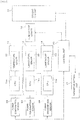
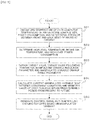
- FIG. 1 is a schematic top view illustrating an example of a data center to which a temperature management system is applied according to a first embodiment
- FIG. 2 is a schematic side view of the data center. It is to be noted that the present embodiment is described by taking a module type data center as an example, in which a computer (server) is cooled using the outside air.
- a computer server
- the module type data center illustrated in FIG. 1 and FIG. 2 has a rectangular prism-shaped container (structure) 10, cooling fan units 12 disposed in the container 10, and multiple racks 13. Multiple computers 14 are housed in each of the racks 13. Also, each of the cooling fan units 12 is provided with multiple cooling fans 12a.
- One of two mutually opposed wall surfaces of the container 10 is provided with an intake vent 11a and the other is provided with an exhaust vent 11b.
- a partition plate 15 is disposed above the space between the cooling fan units 12 and the racks 13.
- the space in the container 10 is divided into an outside air introduction portion 21, a cold aisle 22, a hot aisle 23, and a warm air circulation path 24 by the cooling fan units 12, the racks 13, and the partition plate 15.
- the outside air introduction portion 21 is the space between the intake vent 11a and the cooling fan units 12
- the cold aisle 22 is the space between the cooling fan units 12 and the racks 13
- the hot aisle 23 is the space between the racks 13 and the exhaust vent 11b.
- the racks 13 are each disposed so that the surface thereof facing the cold aisle 22 serves as an air intake surface and the surface facing the hot aisle 23 serves as an air exhaust surface.
- the warm air circulation path 24 is the space above the racks 13 and the partition plate 15 and connects between the hot aisle 23 and the outside air introduction portion 21.
- the warm air circulation path 24 is provided with a damper 17 for adjusting the amount of warm air to be circulated.
- the outside air introduction portion 21 is provided with an evaporation type cooling apparatus 16 that reduces the temperature of air introduced into the outside introduction portion 21, using heat of evaporation of water when the ambient temperature is high.
- the cooling fans 12a of the cooling fan units 12 rotate, thereby introducing air (outside air) to the outside air introduction portion 21 through the intake vent 11a.
- the air introduced into the outside air introduction portion 21 moves to the cold aisle 22 through the cooling fan units 12, further enters the racks 13 through the air intake sides of the racks 13, and cools the computers 14.
- the air (warm air) having an increased temperature after cooling the computers 14 is discharged to the hot aisle 23 through the air exhaust surfaces of the racks 13, and exhausted to the outdoors through the exhaust vent 11b.
- the damper 17 When the ambient temperature is high, the damper 17 is set to a closed state to prevent air from moving to the outside air introduction portion 21 from the hot aisle 23.
- the ambient temperature is much higher, water is supplied to the evaporation type cooling apparatus 16, and outside air is introduced into the outside air introduction portion 21 through the evaporation type cooling apparatus 16 as illustrated in FIG. 3 .
- the outside air passes through the evaporation type cooling apparatus 16, water evaporates and heat of evaporation of water is drawn, and thus air having a temperature lower than the ambient temperature is introduced into the outside air introduction portion 21.
- the damper 17 is set to an open state. Consequently, part of warm air returns to the outside air introduction portion 21 from the hot aisle 23 through the warm air circulation path 24, and thus the temperature of the air introduced into the racks 13 is increased.
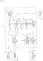
- FIG. 4 is a block diagram of the temperature management system according to the present embodiment.
- the temperature management system has temperature sensors 32, power consumption sensors 34, a temperature sensor 33, a control unit 30, a parameter setting unit 31, and a cooling fan unit 12.
- Each of the temperature sensors 32 is formed in the same chip as CPU 14a, and transmits the temperature of the CPU 14a to the control unit 30 via a communications device (not illustrated) provided in the computers 14.
- control unit 30 and the computers 14 are performed via user datagram protocol (UDP) communication.
- UDP user datagram protocol
- communication between the control unit 30 and the computers 14 is not limited to the UDP communication.
- a temperature sensor disposed in the same chip as the CPU 14a is used as the temperature sensor 32 in the present embodiment, a temperature sensor, which is disposed in close contact with the package of the CPU 14a, may be used.
- the temperature sensor 33 is disposed on the air intake surface side of the racks 13 to detect the temperature of the air supplied into the racks 13. Multiple temperature sensors 33 may be disposed on the air intake surface side of the racks 13.
- the power consumption sensors 34 each detects power consumption of a computer 14. The outputs of the temperature sensor 33 and the power consumption sensors 34 are also transmitted to the control unit 30.
- the control unit 30 includes for instance, a field-programmable gate array (FPGA) or a programmable logic controller (PLC) .
- FPGA field-programmable gate array
- PLC programmable logic controller
- a dedicated program may be read into a specific computer 14 in the racks 13, and the computer 14 may be used as the control unit 30.
- Parameters necessary for control are set to the parameter setting unit 31.
- the parameters set in the parameter setting unit 31 in the present embodiment are a target value of CPU temperature, a target value following parameter, a manipulated variable reduction parameter, and a manipulated variable change range parameter. These parameters will be described later.
- the control unit 30 determines a manipulated variable according to the outputs of the temperature sensors 32, 33, the outputs of the power consumption sensors 34, and the parameters set in the parameter setting unit 31, and controls the cooling fan unit 12 based on the manipulated variable.
- the temperature sensor 32 is an example of a first temperature detection unit, and the temperature sensor 33 is an example of a second temperature detection unit. Also, CPU 14a is an example of a heat generation component, and the cooling fan unit 12 is an example of a cooling apparatus.
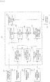
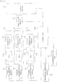
- FIG. 5 is a functional block diagram illustrating the configuration of the control unit 30.
- the control unit 30 has a high level temperature calculation unit 41, an average temperature calculation unit 42, a high level power consumption calculation unit 43, a CPU temperature prediction model unit 44, a correction unit 45, a cost function unit 46, an optimization unit 47, and a control signal generation unit 48.
- the high level temperature calculation unit 41 obtains data of CPU temperature of each computer 14 from the temperature sensors 32, and determines a high level temperature to be evaluated and outputs the determined high level temperature to the cost function unit 46 and the correction unit 45.
- the high level temperature is defined as the highest CPU temperature in the CPU temperatures obtained from the temperature sensors 32.
- the average temperature calculation unit 42 obtains data of temperature of the air supplied to the racks 13 from the temperature sensor 33. The average temperature calculation unit 42 then calculates the average value (hereinafter referred to as an "intake air temperature"), and outputs the result of the calculation to the CPU temperature prediction model unit 44.
- the high level power consumption calculation unit 43 obtains data of power consumption of each computer 14 from the power consumption sensors 34, and determines high level power consumption to be evaluated among the data and outputs the determined high level power consumption to the CPU temperature prediction model unit 44.
- the high level power consumption is defined as the highest power consumption in the power consumption of the computers 14 obtained from the power consumption sensors 34.
- the CPU temperature prediction model unit 44 uses a prediction model to predict the CPU temperature in the future based on the intake air temperature, the high level power consumption, and the manipulated variable of the cooling fans 12a.
- the correction unit 45 corrects the CPU temperature (hereinafter referred to as a "predicted CPU temperature") predicted by the temperature prediction model unit 44 using past data.
- the cost function unit 46 is set with a cost function and calculates a cost by assigning a weight to each of the deviation between a predicted CPU temperature and a target value of the CPU temperature, the change range of the manipulated variable, and the magnitude of the manipulated variable.
- the optimization unit 47 calculates a manipulated variable, which satisfies predetermined constraint conditions and minimizes the cost, based on an optimization algorithm.
- the control signal generation unit 48 generates a pulse signal for controlling the cooling fan units 12 based on the manipulated variable calculated by the optimization unit 47.
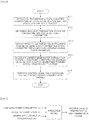
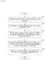
- FIG. 6 is a flow chart illustrating the operation of the temperature management system according to the present embodiment.
- the control unit 30 performs a series of processing illustrated in FIG. 6 every fixed cycle (control cycle).
- step S11 the control unit 30 obtains data of CPU temperature of each computer 14 from the temperature sensors 32. Also, the control unit 30 obtains data of the temperature of the air on the air intake surface side of the racks 13 from the temperature sensor 33, and obtains data of the power consumption of each computer 14 from the power consumption sensors 34.
- step S12 the control unit 30 determines a high level temperature, an intake air temperature, and high level power consumption.
- the high level temperature calculation unit 41 extracts the highest temperature from the CPU temperatures detected by the temperature sensors 32, and determines the highest temperature as the high level temperature. Also, the average temperature calculation unit 42 calculates the average value of the temperatures of the air on the air intake surface side of the racks 13, obtained from the temperature sensor 33, and determines the average value as the intake air temperature. In addition, the high level power consumption calculation unit 43 extracts the highest power consumption from the power consumption of the computers 14 detected by the power consumption sensors 34, and determines the highest power consumption as the high level power consumption.
- the control unit 30 obtains a target value of CPU temperature, a target value following parameter, a manipulated variable reduction parameter, and a manipulated variable change range parameter.
- the target value of CPU temperature may be lower than an allowable upper limit temperature of the CPU 14a, and is set to 90°C, for instance.
- the target value following parameter is a weight parameter for making the value of later-described cost function close to a target value.
- the manipulated variable reduction parameter is a weight parameter for making the magnitude of the manipulated variable for the cost function close to 0.
- the manipulated variable change range parameter is a weight parameter for reducing the change range of the manipulated variable for the cost function.
- step S14 the control unit 30 calculates the current manipulated variable that satisfies constraint conditions and minimizes the value of the cost function within a predetermined period from the present to the future.
- the CPU temperature prediction model unit 44 uses a prediction model to predict a CPU temperature based on a manipulated variable (command value for the revolution speed) u(k) of the cooling fans 12a, an intake air temperature v 1 (k), and a high level power consumption v 2 (k).
- a manipulated variable command value for the revolution speed
- u(k) of the cooling fans 12a an intake air temperature
- v 1 (k) an intake air temperature
- v 2 (k) a high level power consumption
- the prediction model predicts a maximum value of CPU temperature (temperature of a heat generation component) in the future based on the high level power consumption v 2 (k), the intake air temperature v 1 (k), and the manipulated variable u(k) of the cooling fans 12a.
- a maximum value of CPU temperature temperature of a heat generation component
- y(k+1) is future CPU temperature in the subsequent cycle.
- one cycle is set to 1 second.
- a state space model expressed by the following Expression (2) and Expression (3) is used.
- x k + 1 Ax k + B u u k ⁇ d t + B v v k
- y ⁇ k Cx k
- k) is called a state variable.
- v(k) [v 1 (k), v 2 (k)] T
- A is n ⁇ n matrix
- B u is an n-dimensional vector
- Bv is an n ⁇ 2 matrix
- C is a scalar.
- A, B u , B v , and C are determined by conducting an experiment beforehand to perform system identification.
- the dead time d t is set to 12 seconds.
- a model expression method may be a multiple regression equation model or may be data such as a map function.
- the correction unit 45 corrects CPU temperature predicted value tilde ⁇ y ⁇ (k+1
- k y ⁇ k + 1
- control unit 30 uses the optimization unit 47 to calculate the current manipulated variable that satisfies constraint conditions and minimizes the value of the cost function within a predetermined period p from the present to the future.
- the notation of dead time d t in manipulated variable u(k-d t ) is omitted.
- the manipulated variable u in the subsequent cycle in a future period can be expressed as in the following Expression (5) using a change amount ⁇ u in the manipulated variable.
- k u k + i ⁇ 1
- k i 0 , ... , p ⁇ 1
- i is the index that indicates a time in the future period.
- the index i is added to Expression (2), Expression (3), and Expression (4) to obtain expressions as in the following Expression (6), Expression (7), and Expression (8).
- control unit 30 uses Expression (5) to Expression (8) to calculate an input column of the change amount ⁇ u in the manipulated variable by Expression (11) below, the change amount ⁇ u satisfying the constraint conditions in the following Expression (9) and minimizing the value of the cost function J in the following Expression (10).
- p indicates a future period in which prediction is taken into consideration.
- m indicates a future period in which change in the manipulated variable is taken into consideration and p ⁇ m.
- p is set to 100 and m is set to 1.
- Q, R ⁇ u, and R u are weight matrices.
- the first term of Expression (10) indicates an operation for making the controlled variable y close to a target value r, and Q is the weight of the operation, specifically, is the target value following parameter.
- the second term in Expression (10) is the operation for making the change amount ⁇ u in the manipulated variable close to 0.
- R ⁇ u is the weight of the operation, specifically, is the manipulated variable reduction parameter.
- the change amount ⁇ u increases as R ⁇ u decreases, and the change amount ⁇ u decreases as R ⁇ u increases.
- the third term in Expression (10) is an operation for making the manipulated variable close to a target manipulated variable U target .
- U target is set to 0.
- Ru is the weight of the operation for making the manipulated variable close to the target manipulated variable U target , specifically, is the manipulated variable change range parameter.
- Expression (11) determines the optimal input column ⁇ opt (k
- a meta-heuristic numerical solution method for searching for an approximate solution such as a genetic algorithm (GA) or a particle swarm optimization (PSO) may also be used.
- G genetic algorithm
- PSO particle swarm optimization
- KWIK algorithm for solving a quadratic programming problem is used.
- step S15 the control signal generation unit 48 generates a signal for controlling the rotation of the cooling fans 12a based on the current manipulated variable u(k) obtained by the optimization unit 47.
- the optimal manipulated variable u(k) is calculated in consideration of an effect of the intake air temperature and the power consumption from the present to the future using a prediction model that predicts a temperature of a heat generation component based on the revolution speed of the fans, the intake air temperature, and the power consumption.
- the control of the cooling fan units 12 using the manipulated variable u(k) makes it possible to reduce the power consumed by the cooling fan units 12 while properly cooling the heat generation component.
- cooling fan units 12 cooling fans 12a
- the cooling fan units 12 were controlled to maintain the CPU temperature at 90°C or low while the computers 14 were operated so that CPU usage rate was alternately changed between 60% and 50% every 600 seconds.
- the comparative example indicates feed-forward control (hereinafter referred to as "FF control”) in which the manipulated variable u(k) is calculated as indicated in the following Expression (13) based on the difference between intake-side temperature T front (k) and exhaust-side temperature T back (k) of the racks 13.
- FF control feed-forward control
- FIG. 8(a) illustrates a temporal change of the CPU temperature when the cooling fans 12a are controlled in the comparative example.
- the CPU temperature is maintained at 90°C or low.
- the CPU temperature may fall to approximately 80°C, which indicates excessive cooling.
- the control over the revolution speed of the cooling fans 12a is not sufficiently optimized, and power is wastefully consumed.
- FIG. 8(b) illustrates a temporal change of the CPU temperature when the cooling fans 12a are controlled by the present embodiment.
- the CPU temperature is definitely maintained at 90°C or low, and even when the operational state of the CPU changes, the CPU temperature hardly changes and is maintained at approximately 88°C.
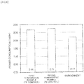
- FIG. 9 is a graph illustrating the results of research of power consumption of the cooling fan units 12 when the cooling fan units 12 are controlled according to the embodiment and the comparative examples.
- first comparative example indicates the power consumption in the case of FF control in which the manipulated variable u(k) is calculated as indicated in Expression (13) based on the difference between the intake-side temperature T front (k) and the exhaust-side temperature T back (k) of the racks 13.
- second comparative example indicates the power consumption in the case where proportional integration (PI) control is performed on the cooling fan units 12 based on the difference between the temperature of the air on the intake surface side of the racks and the temperature of the air on the exhaust surface side of the racks.
- PI proportional integration
- the power consumption was approximately 2.17 kw in the embodiment.
- the power consumption was approximately 2.64 kW
- the power consumption was approximately 2.71 kw.
- the power consumption was reduced by nearly 20% in contrast to the first and second comparative examples.
- FIG. 10 is a block diagram of a temperature management system according to a second embodiment.
- FIG. 11 is a functional block diagram illustrating the configuration of a control unit in the temperature management system according to the second embodiment. It is to be noted that in FIG. 10 and FIG. 11 , the same components as in FIG. 4 and FIG. 5 are labeled with the same symbol, and detailed description thereof is omitted.
- the temperature management system in the present embodiment is basically the same as that of the first embodiment except for that the power consumption sensors 34 (see FIG. 4 ) is not provided.
- the high level power consumption calculation unit 43 (see FIG. 5 ) described in the first embodiment is not provided but a power consumption disturbance model unit 51 and a state estimation unit 52 are provided.
- high level power consumption is treated as unobservable disturbance and the disturbance model unit 51 is set with a disturbance model that expresses a change in the power consumption based on a change in the high level temperature.
- the state estimation unit 52 uses the prediction model and the disturbance model to estimate an operation state of the CPU.
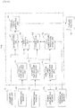
- FIG. 12 is a flow chart illustrating the operation of the temperature management system according to the present embodiment.
- step S21 the control unit 30a obtains data of the CPU temperature of each computer 14 from the temperature sensors 32, and obtains the temperature of the air on the intake surface side of the racks 13 from the temperature sensor 33.
- step S22 the control unit 30a determines a high level temperature and an intake air temperature.
- the high level temperature calculation unit 41 extracts the highest temperature from the CPU temperatures detected by the temperature sensors 32, and determines the highest temperature as the high level temperature. Also, the average temperature calculation unit 42 calculates the average value of the temperatures of the air on the air intake surface side of the racks 13, obtained from the temperature sensor 33, and determines the average value as the intake air temperature.
- step S23 the control unit 30a obtains a target value of CPU temperature, a target value following parameter, a manipulated variable reduction parameter, and a manipulated variable change range parameter.
- step S24 the control unit 30a calculates the current manipulated variable that satisfies constraint conditions and minimizes the value of the cost function within a predetermined period from the present to the future.
- the CPU temperature prediction model unit 44 uses the prediction model and the disturbance model to predict a CPU temperature based on a manipulated variable (command value for the revolution speed) u(k) of the cooling fans 12a, an intake air temperature v 1 (k), and a high level power consumption v 2 (k).
- a manipulated variable command value for the revolution speed
- u(k) of the cooling fans 12a an intake air temperature
- v 1 (k) an intake air temperature
- v 2 (k) high level power consumption
- the prediction model is expressed by Expression (1) described above.
- y'(k+1) is a future CPU temperature in the subsequent cycle.
- the state space model expressed by the above-described Expression (2) and Expression (3) is used.
- the disturbance model defined in the power consumption disturbance model unit 51 is a model which is expressed by Expression (14) and Expression (15) and which assumes high level power consumption d(k) as random step-shaped disturbance and outputs an integration output.
- x d k + 1 A ⁇ x d k + B ⁇ d k ⁇ n d k
- d k C ⁇ x d k
- k) is the state variable of the unobservable disturbance d(k).
- the state estimation unit 52 replaces the state variable x(k
- k) is the state variable of the prediction model after the compensation
- k) is the state variable of the disturbance model after the compensation.
- M is a Kalman gain designed with a Kalman filter and is a two-dimensional vector.
- the correction unit 45 corrects CPU temperature predicted value hat ⁇ y ⁇ (k+1
- k y ⁇ k + 1
- the optimization unit 47 calculates the current manipulated variable that satisfies constraint conditions and minimizes the value of the cost function within a predetermined period from the present to the future.
- the notation of dead time d t in the manipulated variable u(k-d t ) is omitted.
- the manipulated variable u in the subsequent cycle in a future period can be expressed as in the above-described Expression (5) using the change amount ⁇ u in the manipulated variable.
- control unit 30a uses Expression (5) and Expression (20) to Expression (22) to calculate an input column of the change amount ⁇ u in the manipulated variable by Expression (11), the change amount ⁇ u satisfying the constraint conditions in Expression (9) and minimizing the value of the cost function J in Expression (10).
- step S25 the control signal unit 48 generates a signal for controlling the rotation of the cooling fans 12a based on the current manipulated variable u(k) obtained by the optimization unit 47.
- the optimal manipulated variable is calculated in consideration of an effect of the intake air temperature and the power consumption from the present to the future using a prediction model that predicts a temperature of a heat generation component based on the revolution speed of the fans, the intake air temperature, and the power consumption.
- the control of the cooling fan units 12 using the manipulated variable u(k) makes it possible to reduce the power consumed by the cooling fan units 12 while properly cooling the heat generation component.
- a power consumption sensor is unnecessary, and thus there is also an advantage in that the system is simplified compared with the first embodiment.
- FIG. 13 is a block diagram of a temperature management system according to a third embodiment.
- FIG. 14 is a functional block diagram illustrating the configuration of a control unit in the temperature management system according to the third embodiment. It is to be noted that in FIG. 13 and FIG. 14 , the same components as in FIG. 4 and FIG. 5 are labeled with the same symbol, and detailed description thereof is omitted.
- the temperature management system in the present embodiment has a differential pressure sensor 35 that detects a differential pressure between the front and back sides of the racks 13. Also, as seen from FIG. 13 , in a control unit 30b of the temperature management system in the present embodiment, a signal outputted from the differential pressure sensor 35 is inputted to the CPU temperature prediction model unit 44.
- the differential pressure sensor 35 is an example of a pressure difference detection unit.
- FIG. 15 is a flow chart illustrating the operation of the temperature management system according to the present embodiment.
- step S31 the control unit 30b obtains data of the CPU temperature of each computer 14 from the temperature sensors 32, and obtains data of the temperature of the air on the intake surface side of the racks 13 from the temperature sensor 33. Also, the control unit 330b obtains data of the power consumption of each computer 14 from the power consumption sensors 34, and obtains data of a differential pressure (difference between the pressures on the air intake surface side and the air exhaust surface side of the racks 13) from the differential pressure sensor 35.
- step S32 the control unit 30b determines a high level temperature, an intake air temperature, and high level power consumption.
- the high level temperature calculation unit 41 extracts the highest temperature from the CPU temperatures detected by the temperature sensors 32, and determines the highest temperature as the high level temperature. Also, the average temperature calculation unit 42 calculates the average value of the temperatures of the air on the air intake surface side of the racks 13, obtained from the temperature sensor 33, and determines the average value as the intake air temperature. In addition, the high level power consumption calculation unit 43 extracts the highest power consumption from the power consumption of the computers 14 detected by the power consumption sensors 34, and determines the highest power consumption as the high level power consumption.
- step S33 the control unit 30b obtains a target value of CPU temperature, a target following parameter, a manipulated variable reduction parameter, and a manipulated variable change range parameter.
- step S34 the control unit 30b calculates the current manipulated variable that satisfies constraint conditions and minimizes the value of the cost function within a predetermined period from the present to the future.
- the CPU temperature prediction model unit 44 uses the prediction model to predict a CPU temperature based on the manipulated variable (command value for the revolution speed) u(k) of the cooling fans 12a, the intake air temperature v 1 (k), the high level power consumption v 2 (k), and a differential pressure v 3 (k) between the front and back sides of the racks 14.
- y(k+1) is a future CPU temperature in the subsequent cycle.
- one cycle is also set to 1 second.
- k) is called a state function.
- v(k) [v 1 (k), v 2 (k), v 3 (k)] T .
- A is n ⁇ n matrix
- B u is an n-dimensional vector
- B v is an n ⁇ 2 matrix
- C is a scalar.
- A, B u , B v , and C are determined by conducting an experiment beforehand to perform system identification.
- the correction unit 45 corrects CPU temperature predicted value tilde ⁇ y ⁇ (k+1
- the optimization unit 47 calculates the current manipulated variable that satisfies constraint conditions and minimizes the value of the cost function within a predetermined period from the present to the future.
- the notation of dead time d t in the manipulated variable u(k-d t ) is omitted.
- the manipulated variable u in the subsequent cycle in a future period can be expressed as in the above-described Expression (5) using the change amount ⁇ u in the manipulated variable.
- the index i is added to Expression (2), Expression (3), and Expression (4) to obtain expressions as in Expression (6), Expression (7), and Expression (8).
- control unit 30b uses those Expression (5) to Expression (8) to calculate an input column of the change amount ⁇ u in the manipulated variable by Expression (11), the change amount ⁇ u satisfying the constraint conditions in Expression (9) and minimizing the value of the cost function J in Expression (10).
- step S35 the control signal generation unit 48 generates a signal for controlling the rotation of the cooling fans 12a based on the current manipulated variable u(k) obtained by the optimization unit 47.
- the optimal manipulated variable u(k) is calculated based on the revolution speed of the fans, the intake air temperature, the power consumption, and the difference between the pressures on the air intake surface side and the air exhaust surface side of the racks 13.
- the control of the cooling fan units 12 using the manipulated variable u(k) makes it possible to reduce the power consumed by the cooling fan units 12 while properly cooling the heat generation component.
- change of the differential pressure between the front and back sides of the racks 14 is taken into consideration to determine the manipulated variable of the cooling fan units 12, and thus an optimal manipulated variable including an effect such as clogging of a filter is obtainable.
Landscapes
- Engineering & Computer Science (AREA)
- Physics & Mathematics (AREA)
- General Physics & Mathematics (AREA)
- General Engineering & Computer Science (AREA)
- Theoretical Computer Science (AREA)
- Computer Hardware Design (AREA)
- Microelectronics & Electronic Packaging (AREA)
- Thermal Sciences (AREA)
- Condensed Matter Physics & Semiconductors (AREA)
- Power Engineering (AREA)
- Automation & Control Theory (AREA)
- Human Computer Interaction (AREA)
- Remote Sensing (AREA)
- Cooling Or The Like Of Electrical Apparatus (AREA)
Description
- The present invention relates to a temperature management system.
- With the advent of advanced information society in recent years, a large amount of data has become handled by computers, and there have increasing facilities such as data centers in which a great number of computers are installed in a single room and managed in a collective manner. For instance, in a data center, a large number of racks (server racks) are installed in a computer room, and a plurality of computers (servers) are housed in each of the racks. Jobs are organically distributed to those computers according to operational states of the computers, and a large quantity of jobs is efficiently processed.
- However, computers generate a great deal of heat in associated with operating. When the temperature in the computer increases, malfunction, failure, or performance degradation may be caused. To address this, cooling fans are used to take cool air into the racks and discharge the heat generated in the computers to the outside of the racks.
- On the other hand, a great amount of electric power is consumed in the data center and reduction of power consumption is demanded from a viewpoint of energy saving. In order to prevent a computer from causing failure and malfunction due to the heat, cooling fans might be constantly rotated at a maximum revolution speed. However, since a great number of cooling fans are installed in the data center, rotating the cooling fans constantly at a maximum revolution speed causes the power consumption to increase, and reduction of the power consumption cannot be achieved.
- Therefore, in order to reduce the power consumed in a facility such as a data center, it is important to operate cooling equipment efficiently according to the operational states of the computers.
- Patent Document 3 discloses a data processing system including a first sensor to determine an ambient temperature of an environment in which the data processing system is and a controller (e.g., a microcontroller or a microprocessor) coupled to the sensor to control operations of the data processing system according to the ambient temperature.
-
- Patent Document 1: Japanese Laid-open Patent Publication No.
2011-257116 - Patent Document 2: Japanese Laid-open Patent Publication No.
2002-268775 - Patent Document 3:
US2007/067136 - It is an object to provide a temperature management system capable of achieving even more power saving than a conventional system by predicting a change of the ambient temperature and a change of the operational state of a heat generation component to properly control a cooling apparatus.
- The invention is defined in the independent claims. Optional embodiments are set out in the dependent claims.
- With a temperature management system according to the aforementioned aspect, a predicted value of a future temperature of a heat generation component is calculated and a manipulated variable of a cooling apparatus is determined based on the predicted value and a target value, and thus the cooling apparatus can be operated without waste and power consumption can be reduced.
-
-
FIG. 1 is a schematic top view illustrating an example of a data center to which a temperature management system according to a first embodiment is applied. -
FIG. 2 is a schematic side view illustrating an example of a data center to which the temperature management system according to the first embodiment is applied. -
FIG. 3 is a schematic top view illustrating a flow of air when outside air is introduced into a container via an evaporation type cooling apparatus. -
FIG. 4 is a block diagram of the temperature management system according to the first embodiment. -
FIG. 5 is a functional block diagram illustrating the configuration of a control unit of the temperature management system according to the first embodiment. -
FIG. 6 is a flow chart illustrating the operation of the temperature management system according to the first embodiment. -
FIG. 7 is a schematic diagram illustrating a prediction model. -
FIG. 8 is a graph illustrating a temporal change of power consumption according to a comparative example and the embodiment. -
FIG. 9 is a graph illustrating power consumption according to the embodiment and the comparative example. -
FIG. 10 is a block diagram of a temperature management system according to a second embodiment. -
FIG. 11 is a functional block diagram illustrating the configuration of a control unit of the temperature management system according to the second embodiment. -
FIG. 12 is a flow chart illustrating the operation of the temperature management system according to the second embodiment. -
FIG. 13 is a block diagram of a temperature management system according to a third embodiment. -
FIG. 14 is a functional block diagram illustrating the configuration of a control unit of the temperature management system according to the third embodiment. -
FIG. 15 is a flow chart illustrating the operation of the temperature management system according to the third embodiment. - Before an embodiment is described, hereinafter a prelude for easily understanding the embodiments will be described.
- As described above, in order to reduce power consumed by a facility such as a data center, it is important to operate cooling equipment efficiently according to operational states of computers.
- Thus, a control method may be adopted in which a temperature of a component (hereinafter referred to as a "heat generation component") having a large amount of heat generation, such as a central processing unit (CPU) is detected using a temperature sensor, for instance, and the rotation of a cooling fan is controlled so that the temperature of the heat generation component is lower than or equal to a setting temperature. Also, a control method may be adopted in which the difference in the temperature of air between the front and back sides of a rack is detected using a temperature sensor, the rotation speed of a cooling fan is controlled so that the temperature difference is lower than or equal to a setting temperature.
- In the above-described control method, the effect of slow change of the ambient temperature and sudden change of an operational state of a heat generation component is not taken into consideration. Therefore, change of the ambient temperature and change of the operational state of a heat generation component have an effect on the amount of control, and thus feedback control is performed so as to cancel the effect.
- However, in the feedback control, since the amount of control is changed after the temperature difference of air between the front and back sides of a rack changes or the operational state of a heat generation component changes, it is not possible to properly follow a change of the temperature difference or a change of the operational state of a heat generation component. Therefore, excessive cooling may be performed so that the temperature of a computer does not exceed a setting temperature, and power may be wastefully consumed.
- The change of the ambient temperature and the change of the operational state of a heat generation component have a large effect on the entire system. Therefore, in order to achieve further power saving, appropriate measures need to be taken in consideration of an effect on the future due to the change of the ambient temperature and the change of the operational state of a heat generation component.
- In the following embodiments, description will be provided for a temperature management system which is capable of achieving much more power saving than in the conventional system, by predicting a change of the ambient temperature and a change of the operational state of a heat generation component to properly control cooling apparatus.
-
FIG. 1 is a schematic top view illustrating an example of a data center to which a temperature management system is applied according to a first embodiment, andFIG. 2 is a schematic side view of the data center. It is to be noted that the present embodiment is described by taking a module type data center as an example, in which a computer (server) is cooled using the outside air. - The module type data center illustrated in
FIG. 1 and FIG. 2 has a rectangular prism-shaped container (structure) 10,cooling fan units 12 disposed in thecontainer 10, andmultiple racks 13.Multiple computers 14 are housed in each of theracks 13. Also, each of thecooling fan units 12 is provided withmultiple cooling fans 12a. - One of two mutually opposed wall surfaces of the
container 10 is provided with anintake vent 11a and the other is provided with anexhaust vent 11b. In addition, apartition plate 15 is disposed above the space between thecooling fan units 12 and theracks 13. - The space in the
container 10 is divided into an outsideair introduction portion 21, acold aisle 22, ahot aisle 23, and a warmair circulation path 24 by thecooling fan units 12, theracks 13, and thepartition plate 15. The outsideair introduction portion 21 is the space between theintake vent 11a and thecooling fan units 12, thecold aisle 22 is the space between thecooling fan units 12 and theracks 13, and thehot aisle 23 is the space between theracks 13 and theexhaust vent 11b. - The
racks 13 are each disposed so that the surface thereof facing thecold aisle 22 serves as an air intake surface and the surface facing thehot aisle 23 serves as an air exhaust surface. - The warm
air circulation path 24 is the space above theracks 13 and thepartition plate 15 and connects between thehot aisle 23 and the outsideair introduction portion 21. The warmair circulation path 24 is provided with adamper 17 for adjusting the amount of warm air to be circulated. - In the module type data center illustrated in
FIG. 1 and FIG. 2 , the outsideair introduction portion 21 is provided with an evaporationtype cooling apparatus 16 that reduces the temperature of air introduced into theoutside introduction portion 21, using heat of evaporation of water when the ambient temperature is high. - In such a module type data center, the cooling
fans 12a of the coolingfan units 12 rotate, thereby introducing air (outside air) to the outsideair introduction portion 21 through theintake vent 11a. The air introduced into the outsideair introduction portion 21 moves to thecold aisle 22 through the coolingfan units 12, further enters theracks 13 through the air intake sides of theracks 13, and cools thecomputers 14. - The air (warm air) having an increased temperature after cooling the
computers 14 is discharged to thehot aisle 23 through the air exhaust surfaces of theracks 13, and exhausted to the outdoors through theexhaust vent 11b. - When the ambient temperature is high, the
damper 17 is set to a closed state to prevent air from moving to the outsideair introduction portion 21 from thehot aisle 23. When the ambient temperature is much higher, water is supplied to the evaporationtype cooling apparatus 16, and outside air is introduced into the outsideair introduction portion 21 through the evaporationtype cooling apparatus 16 as illustrated inFIG. 3 . When the outside air passes through the evaporationtype cooling apparatus 16, water evaporates and heat of evaporation of water is drawn, and thus air having a temperature lower than the ambient temperature is introduced into the outsideair introduction portion 21. - On the other hand, when the ambient temperature is low and there is a possibility that the temperature of the air introduced into the
racks 13 may fall below an allowable lower limit temperature, thedamper 17 is set to an open state. Consequently, part of warm air returns to the outsideair introduction portion 21 from thehot aisle 23 through the warmair circulation path 24, and thus the temperature of the air introduced into theracks 13 is increased. -
FIG. 4 is a block diagram of the temperature management system according to the present embodiment. - The temperature management system according to the present embodiment has
temperature sensors 32,power consumption sensors 34, atemperature sensor 33, acontrol unit 30, aparameter setting unit 31, and a coolingfan unit 12. - Each of the
temperature sensors 32 is formed in the same chip asCPU 14a, and transmits the temperature of theCPU 14a to thecontrol unit 30 via a communications device (not illustrated) provided in thecomputers 14. - In the present embodiment, it is assumed that transmission and reception of a signal between the
control unit 30 and thecomputers 14 are performed via user datagram protocol (UDP) communication. However, communication between thecontrol unit 30 and thecomputers 14 is not limited to the UDP communication. Also, although a temperature sensor disposed in the same chip as theCPU 14a is used as thetemperature sensor 32 in the present embodiment, a temperature sensor, which is disposed in close contact with the package of theCPU 14a, may be used. - The
temperature sensor 33 is disposed on the air intake surface side of theracks 13 to detect the temperature of the air supplied into theracks 13.Multiple temperature sensors 33 may be disposed on the air intake surface side of theracks 13. Thepower consumption sensors 34 each detects power consumption of acomputer 14. The outputs of thetemperature sensor 33 and thepower consumption sensors 34 are also transmitted to thecontrol unit 30. - The
control unit 30 includes for instance, a field-programmable gate array (FPGA) or a programmable logic controller (PLC) . A dedicated program may be read into aspecific computer 14 in theracks 13, and thecomputer 14 may be used as thecontrol unit 30. - Parameters necessary for control are set to the
parameter setting unit 31. The parameters set in theparameter setting unit 31 in the present embodiment are a target value of CPU temperature, a target value following parameter, a manipulated variable reduction parameter, and a manipulated variable change range parameter. These parameters will be described later. - The
control unit 30 determines a manipulated variable according to the outputs of thetemperature sensors power consumption sensors 34, and the parameters set in theparameter setting unit 31, and controls the coolingfan unit 12 based on the manipulated variable. - The
temperature sensor 32 is an example of a first temperature detection unit, and thetemperature sensor 33 is an example of a second temperature detection unit. Also,CPU 14a is an example of a heat generation component, and the coolingfan unit 12 is an example of a cooling apparatus. -
FIG. 5 is a functional block diagram illustrating the configuration of thecontrol unit 30. As illustrated inFIG. 5 , thecontrol unit 30 has a high leveltemperature calculation unit 41, an averagetemperature calculation unit 42, a high level powerconsumption calculation unit 43, a CPU temperatureprediction model unit 44, acorrection unit 45, acost function unit 46, anoptimization unit 47, and a controlsignal generation unit 48. - The high level
temperature calculation unit 41 obtains data of CPU temperature of eachcomputer 14 from thetemperature sensors 32, and determines a high level temperature to be evaluated and outputs the determined high level temperature to thecost function unit 46 and thecorrection unit 45. In the present embodiment, the high level temperature is defined as the highest CPU temperature in the CPU temperatures obtained from thetemperature sensors 32. - The average
temperature calculation unit 42 obtains data of temperature of the air supplied to theracks 13 from thetemperature sensor 33. The averagetemperature calculation unit 42 then calculates the average value (hereinafter referred to as an "intake air temperature"), and outputs the result of the calculation to the CPU temperatureprediction model unit 44. - The high level power
consumption calculation unit 43 obtains data of power consumption of eachcomputer 14 from thepower consumption sensors 34, and determines high level power consumption to be evaluated among the data and outputs the determined high level power consumption to the CPU temperatureprediction model unit 44. In the present embodiment, the high level power consumption is defined as the highest power consumption in the power consumption of thecomputers 14 obtained from thepower consumption sensors 34. - The CPU temperature
prediction model unit 44 uses a prediction model to predict the CPU temperature in the future based on the intake air temperature, the high level power consumption, and the manipulated variable of the coolingfans 12a. Thecorrection unit 45 corrects the CPU temperature (hereinafter referred to as a "predicted CPU temperature") predicted by the temperatureprediction model unit 44 using past data. - The
cost function unit 46 is set with a cost function and calculates a cost by assigning a weight to each of the deviation between a predicted CPU temperature and a target value of the CPU temperature, the change range of the manipulated variable, and the magnitude of the manipulated variable. - The
optimization unit 47 calculates a manipulated variable, which satisfies predetermined constraint conditions and minimizes the cost, based on an optimization algorithm. - The control
signal generation unit 48 generates a pulse signal for controlling the coolingfan units 12 based on the manipulated variable calculated by theoptimization unit 47. -
FIG. 6 is a flow chart illustrating the operation of the temperature management system according to the present embodiment. Thecontrol unit 30 performs a series of processing illustrated inFIG. 6 every fixed cycle (control cycle). - In the following description, notations such as tilde{y}, bar{A}, hat{x} in sentences are denoted as illustrated in Table 1 in math expressions.
[Table 1] tilde{y} ỹ bar{A} A hat{x} x̂ - First, in step S11, the
control unit 30 obtains data of CPU temperature of eachcomputer 14 from thetemperature sensors 32. Also, thecontrol unit 30 obtains data of the temperature of the air on the air intake surface side of theracks 13 from thetemperature sensor 33, and obtains data of the power consumption of eachcomputer 14 from thepower consumption sensors 34. - Next, the flow proceeds to step S12 and the
control unit 30 determines a high level temperature, an intake air temperature, and high level power consumption. - Specifically, the high level
temperature calculation unit 41 extracts the highest temperature from the CPU temperatures detected by thetemperature sensors 32, and determines the highest temperature as the high level temperature. Also, the averagetemperature calculation unit 42 calculates the average value of the temperatures of the air on the air intake surface side of theracks 13, obtained from thetemperature sensor 33, and determines the average value as the intake air temperature. In addition, the high level powerconsumption calculation unit 43 extracts the highest power consumption from the power consumption of thecomputers 14 detected by thepower consumption sensors 34, and determines the highest power consumption as the high level power consumption. - Next, the flow proceeds to step S13 and the
control unit 30 obtains a target value of CPU temperature, a target value following parameter, a manipulated variable reduction parameter, and a manipulated variable change range parameter. The target value of CPU temperature may be lower than an allowable upper limit temperature of theCPU 14a, and is set to 90°C, for instance. - The target value following parameter is a weight parameter for making the value of later-described cost function close to a target value. Also, the manipulated variable reduction parameter is a weight parameter for making the magnitude of the manipulated variable for the cost function close to 0. Furthermore, the manipulated variable change range parameter is a weight parameter for reducing the change range of the manipulated variable for the cost function.
- Next, the flow proceeds to step S14, and the
control unit 30 calculates the current manipulated variable that satisfies constraint conditions and minimizes the value of the cost function within a predetermined period from the present to the future. - Specifically, the CPU temperature
prediction model unit 44 uses a prediction model to predict a CPU temperature based on a manipulated variable (command value for the revolution speed) u(k) of the coolingfans 12a, an intake air temperature v1(k), and a high level power consumption v2(k). Here, k indicates the current cycle. - As schematically illustrated in
FIG. 7 , the prediction model predicts a maximum value of CPU temperature (temperature of a heat generation component) in the future based on the high level power consumption v2(k), the intake air temperature v1(k), and the manipulated variable u(k) of the coolingfans 12a. In this prediction model, an effect due to a change of the operational state of thecomputers 14 is taken into the high level power consumption and an effect due to a change of the ambient temperature is taken into the intake air temperature. - The prediction model is expressed by following Expression (1).
[Formula 1]
- Here, y(k+1) is future CPU temperature in the subsequent cycle. In the present embodiment, one cycle is set to 1 second. Also, in the present embodiment, a state space model expressed by the following Expression (2) and Expression (3) is used.
[Formula 2]
[Formula 3]
- N-dimensional vector x(k+1|k) is called a state variable. Also, v(k) = [v1(k), v2(k)]T Furthermore, A is n×n matrix, Bu is an n-dimensional vector, Bv is an n×2 matrix, and C is a scalar. A, Bu, Bv, and C are determined by conducting an experiment beforehand to perform system identification.
- Among methods for system identification, prediction error method and subspace identification method are available. Also, when a differential equation of a physical model, which expresses the dynamic characteristics of CPU temperature, can be derived, it is also possible to derive A, Bu, Bv, and C by performing linearization (Taylor expansion) of the differential equation.
- N is determined by the degree nd of the model and waste time (dead time) dt for the revolution speed of the cooling
fans 12a, and is given by n = nd + dt. In the present embodiment, the dead time dt is set to 12 seconds. - It is to be noted that although a state space model is used in the present embodiment, a model expression method may be a multiple regression equation model or may be data such as a map function.
- Next, the
correction unit 45 corrects CPU temperature predicted value tilde{y}(k+1|k) at time k+1 based on the available information at time k or before. Specifically, thecorrection unit 45 corrects tilde{y}(k+1|k) as in the following Expression (4) using the difference between the actual measurement value yreal(k) in the previous cycle (past) and the predicted value y(k|k-1) in the previous cycle.
[Formula 4]
- Next, the
control unit 30 uses theoptimization unit 47 to calculate the current manipulated variable that satisfies constraint conditions and minimizes the value of the cost function within a predetermined period p from the present to the future. Hereinafter, in order to simplify description, the notation of dead time dt in manipulated variable u(k-dt) is omitted. - The manipulated variable u in the subsequent cycle in a future period can be expressed as in the following Expression (5) using a change amount Δu in the manipulated variable.
[Formula 5]
- Here, i is the index that indicates a time in the future period. In order to evaluate the predicted value y in the future period, the index i is added to Expression (2), Expression (3), and Expression (4) to obtain expressions as in the following Expression (6), Expression (7), and Expression (8).
[Formula 6]
[Formula 7]
[Formula 8]
- Next, the
control unit 30 uses Expression (5) to Expression (8) to calculate an input column of the change amount Δu in the manipulated variable by Expression (11) below, the change amount Δu satisfying the constraint conditions in the following Expression (9) and minimizing the value of the cost function J in the following Expression (10).
[Formula 9]
[Formula 10]
[Formula 11]
- Here, p indicates a future period in which prediction is taken into consideration. Also, m indicates a future period in which change in the manipulated variable is taken into consideration and p ≥ m. In the present embodiment, p is set to 100 and m is set to 1.
- Furthermore, Q, RΔu, and Ru are weight matrices. The first term of Expression (10) indicates an operation for making the controlled variable y close to a target value r, and Q is the weight of the operation, specifically, is the target value following parameter.
- The second term in Expression (10) is the operation for making the change amount Δu in the manipulated variable close to 0, RΔu is the weight of the operation, specifically, is the manipulated variable reduction parameter. The change amount Δu increases as RΔu decreases, and the change amount Δu decreases as RΔu increases.
- The third term in Expression (10) is an operation for making the manipulated variable close to a target manipulated variable Utarget. In the present embodiment, Utarget is set to 0. Ru is the weight of the operation for making the manipulated variable close to the target manipulated variable Utarget, specifically, is the manipulated variable change range parameter.
- Expression (11) determines the optimal input column {Δopt(k|k), ..., Δopt(m-1+k|k)} that minimizes the value of the cost function J(k) in Expression (10).
- Next, the leading element Δopt(k|k) in the optimal input column determined by Expression (11) is extracted, and the current manipulated variable u(k) is calculated by the following Expression (12).
[Formula 12]
- As an optimization solver that minimizes the value of the cost function, a meta-heuristic numerical solution method for searching for an approximate solution, such as a genetic algorithm (GA) or a particle swarm optimization (PSO) may also be used. In the present embodiment, KWIK algorithm for solving a quadratic programming problem is used.
- After the current manipulated variable u(k) is calculated in this manner, the flow proceeds to step S15. In step S15, the control
signal generation unit 48 generates a signal for controlling the rotation of the coolingfans 12a based on the current manipulated variable u(k) obtained by theoptimization unit 47. - As described above, in the present embodiment, the optimal manipulated variable u(k) is calculated in consideration of an effect of the intake air temperature and the power consumption from the present to the future using a prediction model that predicts a temperature of a heat generation component based on the revolution speed of the fans, the intake air temperature, and the power consumption. The control of the cooling
fan units 12 using the manipulated variable u(k) makes it possible to reduce the power consumed by the coolingfan units 12 while properly cooling the heat generation component. - Hereinafter, the results of research of CPU temperature when the cooling fan units 12 (cooling
fans 12a) are controlled by the method disclosed in the embodiment will be described in comparison with a comparative example. Here, the coolingfan units 12 were controlled to maintain the CPU temperature at 90°C or low while thecomputers 14 were operated so that CPU usage rate was alternately changed between 60% and 50% every 600 seconds. - The comparative example indicates feed-forward control (hereinafter referred to as "FF control") in which the manipulated variable u(k) is calculated as indicated in the following Expression (13) based on the difference between intake-side temperature Tfront(k) and exhaust-side temperature Tback(k) of the
racks 13.
[Formula 13]
-
FIG. 8(a) illustrates a temporal change of the CPU temperature when the coolingfans 12a are controlled in the comparative example. As seen fromFIG. 8(a) , in the comparative example, the CPU temperature is maintained at 90°C or low. However, the CPU temperature may fall to approximately 80°C, which indicates excessive cooling. In other words, in the comparative example, the control over the revolution speed of the coolingfans 12a is not sufficiently optimized, and power is wastefully consumed. -
FIG. 8(b) illustrates a temporal change of the CPU temperature when the coolingfans 12a are controlled by the present embodiment. As seen fromFIG. 8(b) , in the present embodiment, the CPU temperature is definitely maintained at 90°C or low, and even when the operational state of the CPU changes, the CPU temperature hardly changes and is maintained at approximately 88°C. This demonstrates that the coolingfan units 12 are always properly controllable in the embodiment.
FIG. 9 is a graph illustrating the results of research of power consumption of the coolingfan units 12 when the coolingfan units 12 are controlled according to the embodiment and the comparative examples. Here, first comparative example indicates the power consumption in the case of FF control in which the manipulated variable u(k) is calculated as indicated in Expression (13) based on the difference between the intake-side temperature Tfront (k) and the exhaust-side temperature Tback(k) of theracks 13. Also, second comparative example indicates the power consumption in the case where proportional integration (PI) control is performed on the coolingfan units 12 based on the difference between the temperature of the air on the intake surface side of the racks and the temperature of the air on the exhaust surface side of the racks. - As seen from
FIG. 9 , the power consumption was approximately 2.17 kw in the embodiment. However, in the first comparative example, the power consumption was approximately 2.64 kW, and in the second comparative example, the power consumption was approximately 2.71 kw. In other words, in the present embodiment, the power consumption was reduced by nearly 20% in contrast to the first and second comparative examples. -
FIG. 10 is a block diagram of a temperature management system according to a second embodiment. Also,FIG. 11 is a functional block diagram illustrating the configuration of a control unit in the temperature management system according to the second embodiment. It is to be noted that inFIG. 10 andFIG. 11 , the same components as inFIG. 4 andFIG. 5 are labeled with the same symbol, and detailed description thereof is omitted. - As seen from
FIG. 10 , the temperature management system in the present embodiment is basically the same as that of the first embodiment except for that the power consumption sensors 34 (seeFIG. 4 ) is not provided. In addition, as seen fromFIG. 11 , incontrol unit 30a of the temperature management system in the present embodiment, the high level power consumption calculation unit 43 (seeFIG. 5 ) described in the first embodiment is not provided but a power consumptiondisturbance model unit 51 and astate estimation unit 52 are provided. - In the present embodiment, high level power consumption is treated as unobservable disturbance and the
disturbance model unit 51 is set with a disturbance model that expresses a change in the power consumption based on a change in the high level temperature. Thestate estimation unit 52 uses the prediction model and the disturbance model to estimate an operation state of the CPU. -
FIG. 12 is a flow chart illustrating the operation of the temperature management system according to the present embodiment. - First, in step S21, the
control unit 30a obtains data of the CPU temperature of eachcomputer 14 from thetemperature sensors 32, and obtains the temperature of the air on the intake surface side of theracks 13 from thetemperature sensor 33. - Next, the flow proceeds to step S22 and the
control unit 30a determines a high level temperature and an intake air temperature. - Specifically, the high level
temperature calculation unit 41 extracts the highest temperature from the CPU temperatures detected by thetemperature sensors 32, and determines the highest temperature as the high level temperature. Also, the averagetemperature calculation unit 42 calculates the average value of the temperatures of the air on the air intake surface side of theracks 13, obtained from thetemperature sensor 33, and determines the average value as the intake air temperature. - Next, the flow proceeds to step S23 and the
control unit 30a obtains a target value of CPU temperature, a target value following parameter, a manipulated variable reduction parameter, and a manipulated variable change range parameter. - Next, the flow proceeds to step S24, and the
control unit 30a calculates the current manipulated variable that satisfies constraint conditions and minimizes the value of the cost function within a predetermined period from the present to the future. - Specifically, the CPU temperature
prediction model unit 44 uses the prediction model and the disturbance model to predict a CPU temperature based on a manipulated variable (command value for the revolution speed) u(k) of the coolingfans 12a, an intake air temperature v1(k), and a high level power consumption v2(k). - The prediction model is expressed by Expression (1) described above. y'(k+1) is a future CPU temperature in the subsequent cycle. Also in the present embodiment, the state space model expressed by the above-described Expression (2) and Expression (3) is used.
- The disturbance model defined in the power consumption
disturbance model unit 51 is a model which is expressed by Expression (14) and Expression (15) and which assumes high level power consumption d(k) as random step-shaped disturbance and outputs an integration output.
[Formula 14]
[Formula 15]
- Here, bar{A} = 1, bar{B} = 1, bar{C} = 1, and nd(k) is a random noise. Also, Xd(k+1|k) is the state variable of the unobservable disturbance d(k).
- The
state estimation unit 52 replaces the state variable x(k|k) of the prediction model and the state variable xd(k+1|k) of the disturbance model with hat{x}(k|k) and hat{x}d(k|k). Then hat{x}(k|k) and hat{x}d(k|k) are each compensated based on a change in the actual measurement value yreal(k) of the CPU temperature by a state observer that is expressed by Expression (16), Expression (17), and Expression (18) in the following.
[Formula 16]
[Formula 17]
[Formula 18]
- Here, hat{x}(k+1|k) is the state variable of the prediction model after the compensation, and hat{x}d(k+1|k) is the state variable of the disturbance model after the compensation. M is a Kalman gain designed with a Kalman filter and is a two-dimensional vector.
- Next, the
correction unit 45 corrects CPU temperature predicted value hat{y}(k+1|k) at time k+1 based on the available information determined by Expression (17) and Expression (18) at time k or before. Specifically, thecorrection unit 45 corrects hat{y}(k+1|k) as in the following Expression (19) using the difference between the actual measurement value yreal(k) in the previous cycle (past) and the predicted value hat{y}(k|k-1) in the previous cycle.
[Formula 19]
- Next, the
optimization unit 47 calculates the current manipulated variable that satisfies constraint conditions and minimizes the value of the cost function within a predetermined period from the present to the future. Hereinafter, in order to simplify description, the notation of dead time dt in the manipulated variable u(k-dt) is omitted. - The manipulated variable u in the subsequent cycle in a future period can be expressed as in the above-described Expression (5) using the change amount Δu in the manipulated variable.
- In order to evaluate the predicted value y in the future period, a prediction model is given by Expression (17) and Expression (18) and the index i is added to correction portion of Expression (4) to obtain expressions as in the following Expression (20), Expression (21), and Expression (22) .
[Formula 20]
[Formula 21]
[Formula 22]
- Next, the
control unit 30a uses Expression (5) and Expression (20) to Expression (22) to calculate an input column of the change amount Δu in the manipulated variable by Expression (11), the change amount Δu satisfying the constraint conditions in Expression (9) and minimizing the value of the cost function J in Expression (10). - Next, the leading element Δuopt(k|k) in the optimal input column determined by Expression (11) is extracted, and the current manipulated variable is calculated by Expression (12).
- Subsequently, in step S25, the
control signal unit 48 generates a signal for controlling the rotation of the coolingfans 12a based on the current manipulated variable u(k) obtained by theoptimization unit 47. - As described above, in the present embodiment, the optimal manipulated variable is calculated in consideration of an effect of the intake air temperature and the power consumption from the present to the future using a prediction model that predicts a temperature of a heat generation component based on the revolution speed of the fans, the intake air temperature, and the power consumption. The control of the cooling
fan units 12 using the manipulated variable u(k) makes it possible to reduce the power consumed by the coolingfan units 12 while properly cooling the heat generation component. - In the present embodiment, a power consumption sensor is unnecessary, and thus there is also an advantage in that the system is simplified compared with the first embodiment.
-
FIG. 13 is a block diagram of a temperature management system according to a third embodiment.FIG. 14 is a functional block diagram illustrating the configuration of a control unit in the temperature management system according to the third embodiment. It is to be noted that inFIG. 13 andFIG. 14 , the same components as inFIG. 4 andFIG. 5 are labeled with the same symbol, and detailed description thereof is omitted. - As seen from
FIG. 13 , the temperature management system in the present embodiment has adifferential pressure sensor 35 that detects a differential pressure between the front and back sides of theracks 13. Also, as seen fromFIG. 13 , in acontrol unit 30b of the temperature management system in the present embodiment, a signal outputted from thedifferential pressure sensor 35 is inputted to the CPU temperatureprediction model unit 44. Thedifferential pressure sensor 35 is an example of a pressure difference detection unit. -
FIG. 15 is a flow chart illustrating the operation of the temperature management system according to the present embodiment. - First, in step S31, the
control unit 30b obtains data of the CPU temperature of eachcomputer 14 from thetemperature sensors 32, and obtains data of the temperature of the air on the intake surface side of theracks 13 from thetemperature sensor 33. Also, the control unit 330b obtains data of the power consumption of eachcomputer 14 from thepower consumption sensors 34, and obtains data of a differential pressure (difference between the pressures on the air intake surface side and the air exhaust surface side of the racks 13) from thedifferential pressure sensor 35. - Next, the flow proceeds to step S32 and the
control unit 30b determines a high level temperature, an intake air temperature, and high level power consumption. - Specifically, the high level
temperature calculation unit 41 extracts the highest temperature from the CPU temperatures detected by thetemperature sensors 32, and determines the highest temperature as the high level temperature. Also, the averagetemperature calculation unit 42 calculates the average value of the temperatures of the air on the air intake surface side of theracks 13, obtained from thetemperature sensor 33, and determines the average value as the intake air temperature. In addition, the high level powerconsumption calculation unit 43 extracts the highest power consumption from the power consumption of thecomputers 14 detected by thepower consumption sensors 34, and determines the highest power consumption as the high level power consumption. - Next, the flow proceeds to step S33 and the
control unit 30b obtains a target value of CPU temperature, a target following parameter, a manipulated variable reduction parameter, and a manipulated variable change range parameter. - Next, the flow proceeds to step S34, and the
control unit 30b calculates the current manipulated variable that satisfies constraint conditions and minimizes the value of the cost function within a predetermined period from the present to the future. - Specifically, the CPU temperature
prediction model unit 44 uses the prediction model to predict a CPU temperature based on the manipulated variable (command value for the revolution speed) u(k) of the coolingfans 12a, the intake air temperature v1(k), the high level power consumption v2(k), and a differential pressure v3(k) between the front and back sides of theracks 14. - The prediction model is expressed by the following Expression (23).
[Formula 23]
- Here, y(k+1) is a future CPU temperature in the subsequent cycle. In the present embodiment, one cycle is also set to 1 second. Also, in the present embodiment, the state space model expressed by the following Expression (24) and Expression (25) is used.
[Formula 24]
[Formula 25]
- The n-dimensional vector x(k+1|k) is called a state function. Also, v(k) = [v1(k), v2(k), v3(k)]T. Furthermore, A is n×n matrix, Bu is an n-dimensional vector, Bv is an n×2 matrix, and C is a scalar. A, Bu, Bv, and C are determined by conducting an experiment beforehand to perform system identification.
- Next, the
correction unit 45 corrects CPU temperature predicted value tilde{y}(k+1|k) at time k+1 by Expression (24) based on the available information at time k or before. Specifically, thecorrection unit 45 corrects tilde{y}(k+1|k) as in Expression (4) using the difference between the actual measurement value yreal(k) in the previous cycle (past) and the predicted value y(k|k-1) in the previous cycle. - Next, the
optimization unit 47 calculates the current manipulated variable that satisfies constraint conditions and minimizes the value of the cost function within a predetermined period from the present to the future. Hereinafter, in order to simplify description, the notation of dead time dt in the manipulated variable u(k-dt) is omitted. - The manipulated variable u in the subsequent cycle in a future period can be expressed as in the above-described Expression (5) using the change amount Δu in the manipulated variable.
- In order to evaluate the predicted value y in the future period, the index i is added to Expression (2), Expression (3), and Expression (4) to obtain expressions as in Expression (6), Expression (7), and Expression (8).
- Next, the
control unit 30b uses those Expression (5) to Expression (8) to calculate an input column of the change amount Δu in the manipulated variable by Expression (11), the change amount Δu satisfying the constraint conditions in Expression (9) and minimizing the value of the cost function J in Expression (10). - Next, the leading element Δuopt(k|k) in the optimal input column determined by Expression (11) is extracted, and the current manipulated variable is calculated by Expression (12).
- Subsequently, the flow proceeds to step S35, the control
signal generation unit 48 generates a signal for controlling the rotation of the coolingfans 12a based on the current manipulated variable u(k) obtained by theoptimization unit 47. - As described above, in the present embodiment, the optimal manipulated variable u(k) is calculated based on the revolution speed of the fans, the intake air temperature, the power consumption, and the difference between the pressures on the air intake surface side and the air exhaust surface side of the
racks 13. The control of the coolingfan units 12 using the manipulated variable u(k) makes it possible to reduce the power consumed by the coolingfan units 12 while properly cooling the heat generation component. In the present embodiment, change of the differential pressure between the front and back sides of theracks 14 is taken into consideration to determine the manipulated variable of the coolingfan units 12, and thus an optimal manipulated variable including an effect such as clogging of a filter is obtainable.
Claims (10)
- A temperature management system comprising:a first temperature detection unit (32) configured to detect a temperature of a heat generation component (14a) in an electronic device (14);a cooling apparatus (12) configured to circulate air in the electronic device (14) and to cool the heat generation component (14a) ;a second temperature detection unit (33) configured to detect a temperature of air flowing in the electronic device (14);a parameter setting unit (31) configured to set a target value of the temperature of the heat generation component (14a); anda control unit (30, 30a, 30b) configured to calculate a predicted value of a future temperature of the heat generation component (14a) based on outputs of the first temperature detection unit (32) and the second temperature detection unit (33), and a power consumption of the electronic device (14), and configured to determine a manipulated variable of the cooling apparatus (12) based on the predicted value and the target value,and characterized in that
the control unit (30, 30a, 30b) includes:a prediction model unit (44) set with a prediction model to calculate the predicted value of the future temperature of the heat generation component (14a) based on the temperature of the air flowing in the electronic device (14), the manipulated variable, and the power consumption of the electronic device (14), and configured to calculate the predicted value using the prediction model;a correction unit (45) configured to correct the predicted value calculated by the prediction model unit (44);a cost function unit (46) set with a cost function to calculate a cost by assigning a weight to a deviation between the predicted value corrected by the correction unit (45) and the target value, and configured to calculate the cost using the cost function; andan optimization unit (47) configured to calculate a change amount of manipulated variable that satisfies a preset constraint condition and minimizes the cost calculated by the cost function unit (46) within a predetermined period from present to future, and to calculate the manipulated variable of the cooling apparatus (12) based on the change amount. - The temperature management system according to claim 1, wherein
the system further comprises a power consumption detection unit (34) configured to detect the power consumption of the electronic device (14), and
an output of the power consumption detection unit (34) is transmitted to the prediction model unit (44) of the control unit (30, 30b). - The temperature management system according to claim 2, wherein
the control unit (30, 30b) includes:a high level temperature calculation unit (41) configured to determine a high level temperature to be evaluated, from the output of the first temperature detection unit (32); anda high level power consumption calculation unit (43) configured to determine a high level power consumption to be evaluated, from the output of the power consumption detection unit (34). - The temperature management system according to claim 3, wherein
the prediction model unit (41) is configured to calculate the predicted value of the future temperature of the heat generation component (14a) based on the temperature of the air flowing in the electronic device (14), the manipulated variable, and the high level power consumption, and
the correction unit (45) is configured to correct a current predicted value using a difference between a past high level temperature and a past predicted value. - The temperature management system according to claim 1, wherein
the system further comprises a high level temperature calculation unit (41) configured to determine a high level temperature to be evaluated, from the output of the first temperature detection unit (32),
the control unit (30a) includes:a disturbance model unit (51) set with a disturbance model to express the power consumption of the electronic device (14) as unobservable disturbance based on a change in the high level temperature; anda state estimation unit (52) configured to estimate an operational state of the electronic device (14) using the disturbance model and the prediction model,the prediction model unit (44) is configured to calculate the predicted value using the operational state estimated by the state estimation unit (52), and
the correction unit (45) is configured to correct a current predicted value using a difference between a past high level temperature and a past predicted value. - The temperature management system according to claim 1, wherein the system further comprises a pressure difference detection unit (35) configured to detect a pressure difference between an intake surface side and an exhaust surface side of the electronic device (14), and
the prediction model unit (44) is configured to use an output of the pressure difference detection unit (35) when predicting the temperature of the heat generation component (14a). - The temperature management system according to any one of claims 1 to 6, wherein the cost function includes a target value following parameter to makes a controlled variable close to the target value, a manipulated variable reduction parameter to make a change amount in the manipulated variable close to 0, and a manipulated variable change range parameter to make the manipulated variable close to a target manipulated variable.
- The temperature management system according to any one of claims 1 to 7, wherein
the electronic device is a computer (14) housed in a rack (13), and
the heat generation component is a CPU (14a). - The temperature management system according to claim 8, wherein a plurality of the electronic devices (14) are housed in the rack (13).
- The temperature management system according to claim 9, wherein
the rack (13) is disposed in a structure (10) provided with an intake vent (11a) and an exhaust vent (11b) that communicate with outdoors, and
the cooling apparatus (12) is configured to supply air into the electronic device (14), the air being introduced into the structure (10) through the intake vent (11a).
Applications Claiming Priority (1)
| Application Number | Priority Date | Filing Date | Title |
|---|---|---|---|
| PCT/JP2013/057595 WO2014147691A1 (en) | 2013-03-18 | 2013-03-18 | Temperature management system |
Publications (3)
| Publication Number | Publication Date |
|---|---|
| EP2977852A1 EP2977852A1 (en) | 2016-01-27 |
| EP2977852A4 EP2977852A4 (en) | 2016-05-04 |
| EP2977852B1 true EP2977852B1 (en) | 2019-03-13 |
Family
ID=51579431
Family Applications (1)
| Application Number | Title | Priority Date | Filing Date |
|---|---|---|---|
| EP13878781.7A Active EP2977852B1 (en) | 2013-03-18 | 2013-03-18 | Temperature management system |
Country Status (4)
| Country | Link |
|---|---|
| US (1) | US9958916B2 (en) |
| EP (1) | EP2977852B1 (en) |
| JP (1) | JP5994927B2 (en) |
| WO (1) | WO2014147691A1 (en) |
Families Citing this family (34)
| Publication number | Priority date | Publication date | Assignee | Title |
|---|---|---|---|---|
| JP6136596B2 (en) * | 2013-06-05 | 2017-05-31 | 富士通株式会社 | Supervisory control device, supervisory control method, and supervisory control program |
| US11162912B2 (en) | 2015-09-11 | 2021-11-02 | KABUSHI Kl KAISHA TOSHIBA | Electronic apparatus, index calculating method, and computer program product |
| US9820409B1 (en) * | 2015-09-28 | 2017-11-14 | Amazon Technologies, Inc. | Rack cooling system |
| US10368466B1 (en) * | 2015-10-06 | 2019-07-30 | Amazon Technologies, Inc. | Rack mountable cooling canister |
| TW201714042A (en) * | 2015-10-13 | 2017-04-16 | 鴻海精密工業股份有限公司 | Container data center |
| US10222843B1 (en) * | 2016-03-16 | 2019-03-05 | ZT Group Int'l, Inc. | Server platform thermal control system using component power |
| US10585466B1 (en) | 2016-03-16 | 2020-03-10 | ZT Group Int'l, Inc. | Power saving fan control with anti fan-oscillation feature |
| US11216048B1 (en) | 2016-03-16 | 2022-01-04 | ZT Group Int'l, Inc. | System and method for controlling computer cooling using ideal cooling system settings, actual cooling system settings, and computer component data |
| JP2017195494A (en) * | 2016-04-20 | 2017-10-26 | 富士通株式会社 | Line card and line card control method |
| US10303139B2 (en) * | 2016-06-01 | 2019-05-28 | Creative Esp Incorporated | System and method for managing electrical components for energy usage |
| US10394294B2 (en) * | 2016-08-25 | 2019-08-27 | Microchip Technology Incorporated | Predictive thermal control management using temperature and power sensors |
| JP2018060271A (en) * | 2016-10-03 | 2018-04-12 | 富士通株式会社 | Management device, control method of management device, control program of management device and information processing system |
| US11076509B2 (en) | 2017-01-24 | 2021-07-27 | The Research Foundation for the State University | Control systems and prediction methods for it cooling performance in containment |
| US10478929B2 (en) | 2017-03-08 | 2019-11-19 | A3 Labs LLC | Energy source supply systems, energy source supply devices, and related methods |
| KR102474460B1 (en) * | 2017-08-23 | 2022-12-07 | 삼성전자 주식회사 | electronic device and method for controlling of operation the same |
| US10613600B2 (en) * | 2017-11-02 | 2020-04-07 | Microsoft Technology Licensing, Llc | Advanced power based thermal control systems |
| JP6923803B2 (en) | 2017-12-06 | 2021-08-25 | 富士通株式会社 | Information processing equipment, power saving transition program, and power saving transition method |
| CN109032301A (en) * | 2018-08-02 | 2018-12-18 | 郑州云海信息技术有限公司 | A kind of general server automatic heat radiation regulator control system and method |
| CN109189190B (en) * | 2018-10-16 | 2020-07-14 | 西安交通大学 | Data center heat management method based on temperature prediction |
| JP6974291B2 (en) * | 2018-11-09 | 2021-12-01 | 東芝三菱電機産業システム株式会社 | Semiconductor device |
| WO2020189001A1 (en) * | 2019-03-18 | 2020-09-24 | 日本電気株式会社 | Data center air conditioning control device, method, non-transitory computer readable medium, and air conditioning system |
| CN113853586A (en) * | 2019-03-28 | 2021-12-28 | 西门子股份公司 | Thermal management system, method and device for monitoring health of electronic device |
| EP3734413A1 (en) | 2019-04-30 | 2020-11-04 | Ovh | Method and system for supervising a health of a server infrastructure |
| CN110543196B (en) * | 2019-08-13 | 2021-02-12 | 华为技术有限公司 | Control method and control device for heat dissipation element |
| CN112443507B (en) * | 2019-08-30 | 2022-06-28 | 宏碁股份有限公司 | Intelligent fan rotating speed adjusting method, computer device and server |
| CN111026603B (en) * | 2019-10-25 | 2021-04-23 | 南京大学 | On-chip network temperature prediction method and device, equipment and storage medium |
| CN111796647B (en) * | 2020-06-30 | 2022-11-18 | 联想(北京)有限公司 | Detection method and electronic equipment |
| JP2022044506A (en) * | 2020-09-07 | 2022-03-17 | 株式会社日立製作所 | Electronic apparatus, fan control method, and program |
| US11946661B2 (en) * | 2021-01-29 | 2024-04-02 | Robert M. Rohde | Variable airflow energy efficient HVAC systems and methods |
| CN113534703B (en) * | 2021-07-07 | 2022-12-06 | 国网福建省电力有限公司检修分公司 | Heating and ventilation combined machine energy-saving system and control method thereof |
| WO2023043872A1 (en) * | 2021-09-16 | 2023-03-23 | Vertiv Corporation | Systems and methods for environmental control of an enclosure |
| CN114355999B (en) * | 2021-12-24 | 2023-05-23 | 交控科技股份有限公司 | Intelligent temperature control cabinet applied to train, control method and equipment |
| US20230376093A1 (en) * | 2022-05-19 | 2023-11-23 | Honeywell International Inc. | System and method for proactively controlling an environmental condition in a server rack of a data center based at least in part on server load |
| CN114777958B (en) * | 2022-06-20 | 2022-10-28 | 深圳比特微电子科技有限公司 | Chip heat dissipation condition detection method and device, electronic equipment and storage medium |
Family Cites Families (24)
| Publication number | Priority date | Publication date | Assignee | Title |
|---|---|---|---|---|
| KR910004393B1 (en) * | 1987-04-22 | 1991-06-27 | 미츠비시 덴키 가부시키가이샤 | Frequency control apparatus of a multi-refregeration cycle system |
| US5486995A (en) * | 1994-03-17 | 1996-01-23 | Dow Benelux N.V. | System for real time optimization |
| JP3769200B2 (en) | 2001-03-06 | 2006-04-19 | インターナショナル・ビジネス・マシーンズ・コーポレーション | Cooling fan control method and apparatus |
| US6721672B2 (en) * | 2002-01-02 | 2004-04-13 | American Power Conversion | Method and apparatus for preventing overloads of power distribution networks |
| JP4152348B2 (en) * | 2004-06-03 | 2008-09-17 | 株式会社ソニー・コンピュータエンタテインメント | Electronic device cooling apparatus, electronic device system, and electronic device cooling method |
| US7347621B2 (en) * | 2004-07-16 | 2008-03-25 | International Business Machines Corporation | Method and system for real-time estimation and prediction of the thermal state of a microprocessor unit |
| US7138781B2 (en) * | 2004-11-24 | 2006-11-21 | Standard Microsystems Corporation | Adaptive controller for PC cooling fans |
| US7490479B2 (en) * | 2005-03-30 | 2009-02-17 | Intel Corporation | Method and system of advanced fan speed control |
| US8374730B2 (en) * | 2005-08-25 | 2013-02-12 | Apple Inc. | Methods and apparatuses for dynamic thermal control |
| US8762097B2 (en) * | 2006-08-04 | 2014-06-24 | Apple Inc. | Method and apparatus for a thermal control system based on virtual temperature sensor |
| JP4807352B2 (en) * | 2007-12-25 | 2011-11-02 | 三菱電機株式会社 | Temperature detection system |
| US8310829B2 (en) * | 2008-05-05 | 2012-11-13 | Carrier Corporation | Integrated computer equipment container and cooling unit |
| JP5189921B2 (en) * | 2008-08-02 | 2013-04-24 | レノボ・シンガポール・プライベート・リミテッド | Computer heat dissipation system |
| US8190276B2 (en) * | 2008-11-21 | 2012-05-29 | Oracle America, Inc. | Method and apparatus for controlling temperature variations in a computer system |
| US9069345B2 (en) * | 2009-01-23 | 2015-06-30 | Mks Instruments, Inc. | Controlling a manufacturing process with a multivariate model |
| US8086359B2 (en) * | 2009-02-23 | 2011-12-27 | Novell, Inc. | Dynamic thermal load balancing |
| JP5375948B2 (en) | 2009-03-19 | 2013-12-25 | 富士通株式会社 | Electronic device having cooling device and cooling program |
| JP5206602B2 (en) * | 2009-06-30 | 2013-06-12 | 富士通株式会社 | Air conditioning control device, air conditioning control method, and air conditioning control program |
| GB0922095D0 (en) * | 2009-12-17 | 2010-02-03 | Bripco Bvba | Data centre building and rack therefor |
| JP2011257116A (en) | 2010-06-11 | 2011-12-22 | Fujitsu Ltd | Computer room air conditioning system, control unit thereof, and program |
| US8868250B2 (en) * | 2010-09-28 | 2014-10-21 | Cisco Technology, Inc. | Fan speed control |
| JP5672099B2 (en) * | 2011-03-22 | 2015-02-18 | 富士通株式会社 | Device equipped with electronic device, cooling program for device equipped with electronic device, and method for cooling device equipped with electronic device |
| US9195243B2 (en) * | 2011-05-24 | 2015-11-24 | Aten International Co., Ltd. | System and method of safe and effective energy usage and conservation for data centers with rack power distribution units |
| US8600561B1 (en) * | 2012-09-30 | 2013-12-03 | Nest Labs, Inc. | Radiant heating controls and methods for an environmental control system |
-
2013
- 2013-03-18 WO PCT/JP2013/057595 patent/WO2014147691A1/en active Application Filing
- 2013-03-18 EP EP13878781.7A patent/EP2977852B1/en active Active
- 2013-03-18 JP JP2015506379A patent/JP5994927B2/en active Active
-
2015
- 2015-09-10 US US14/849,953 patent/US9958916B2/en active Active
Non-Patent Citations (1)
| Title |
|---|
| None * |
Also Published As
| Publication number | Publication date |
|---|---|
| US20150378404A1 (en) | 2015-12-31 |
| EP2977852A1 (en) | 2016-01-27 |
| WO2014147691A1 (en) | 2014-09-25 |
| US9958916B2 (en) | 2018-05-01 |
| JPWO2014147691A1 (en) | 2017-02-16 |
| JP5994927B2 (en) | 2016-09-21 |
| EP2977852A4 (en) | 2016-05-04 |
Similar Documents
| Publication | Publication Date | Title |
|---|---|---|
| EP2977852B1 (en) | Temperature management system | |
| US9645622B2 (en) | Temperature management system | |
| US10238009B2 (en) | Coolant and ambient temperature control for chillerless liquid cooled data centers | |
| US9291358B2 (en) | Accuracy-optimal control decisions for systems | |
| US9420726B2 (en) | Container-type data center and air-conditioning control method | |
| US20080232974A1 (en) | Fan rotation control method, fan rotation control system, and fan rotation control program | |
| US20190200489A1 (en) | Controlling operational parameters of a cooling unit | |
| US20130073096A1 (en) | Proactive cooling control using power consumption trend analysis | |
| US20140020418A1 (en) | Data center cooling system | |
| US10061365B2 (en) | Temperature prediction system using prediction models, temperature prediction method using prediction models, and non-transitory computer readable recording medium having therein program for temperature prediction using prediction models | |
| US20120215373A1 (en) | Performance optimization in computer component rack | |
| US9814161B2 (en) | Electronic device rack and information processing apparatus | |
| US20170135250A1 (en) | Data center system, control method of data center system, and recording medium recording control program of data center system | |
| US8897925B2 (en) | Heat dissipation control system and control method thereof | |
| JP5467929B2 (en) | Function generating apparatus and function generating method | |
| JP6083305B2 (en) | Electronic equipment cooling system | |
| JP6277777B2 (en) | Air conditioning control system and air conditioning control method | |
| JP7088323B2 (en) | Server racks, controls, cooling methods, and programs | |
| Liu et al. | Real-time temperature predictions via state-space model and parameters identification within rack-based cooling data centers | |
| Sundaralingam et al. | Server heat load based CRAC fan controller paired with rear door heat exchanger | |
| WO2024112687A1 (en) | Cooling system with in-series high-temperature and low-temperature circuits | |
| JP2014192192A (en) | Electronic apparatus cooling system |
Legal Events
| Date | Code | Title | Description |
|---|---|---|---|
| PUAI | Public reference made under article 153(3) epc to a published international application that has entered the european phase |
Free format text: ORIGINAL CODE: 0009012 |
|
| 17P | Request for examination filed |
Effective date: 20150911 |
|
| AK | Designated contracting states |
Kind code of ref document: A1 Designated state(s): AL AT BE BG CH CY CZ DE DK EE ES FI FR GB GR HR HU IE IS IT LI LT LU LV MC MK MT NL NO PL PT RO RS SE SI SK SM TR |
|
| AX | Request for extension of the european patent |
Extension state: BA ME |
|
| A4 | Supplementary search report drawn up and despatched |
Effective date: 20160404 |
|
| RIC1 | Information provided on ipc code assigned before grant |
Ipc: H05K 7/20 20060101ALI20160329BHEP Ipc: G06F 1/20 20060101AFI20160329BHEP Ipc: G05D 23/19 20060101ALI20160329BHEP Ipc: F24F 7/06 20060101ALI20160329BHEP Ipc: H01L 23/467 20060101ALI20160329BHEP |
|
| DAX | Request for extension of the european patent (deleted) | ||
| GRAP | Despatch of communication of intention to grant a patent |
Free format text: ORIGINAL CODE: EPIDOSNIGR1 |
|
| STAA | Information on the status of an ep patent application or granted ep patent |
Free format text: STATUS: GRANT OF PATENT IS INTENDED |
|
| INTG | Intention to grant announced |
Effective date: 20181019 |
|
| RIN1 | Information on inventor provided before grant (corrected) |
Inventor name: ENDO, HIROSHI Inventor name: OGAWA, MASATOSHI Inventor name: KONDO, MASAO Inventor name: FUKUDA, HIROYUKI |
|
| GRAS | Grant fee paid |
Free format text: ORIGINAL CODE: EPIDOSNIGR3 |
|
| GRAA | (expected) grant |
Free format text: ORIGINAL CODE: 0009210 |
|
| STAA | Information on the status of an ep patent application or granted ep patent |
Free format text: STATUS: THE PATENT HAS BEEN GRANTED |
|
| AK | Designated contracting states |
Kind code of ref document: B1 Designated state(s): AL AT BE BG CH CY CZ DE DK EE ES FI FR GB GR HR HU IE IS IT LI LT LU LV MC MK MT NL NO PL PT RO RS SE SI SK SM TR |
|
| REG | Reference to a national code |
Ref country code: GB Ref legal event code: FG4D |
|
| REG | Reference to a national code |
Ref country code: CH Ref legal event code: EP Ref country code: AT Ref legal event code: REF Ref document number: 1108569 Country of ref document: AT Kind code of ref document: T Effective date: 20190315 |
|
| REG | Reference to a national code |
Ref country code: IE Ref legal event code: FG4D |
|
| REG | Reference to a national code |
Ref country code: DE Ref legal event code: R096 Ref document number: 602013052478 Country of ref document: DE |
|
| REG | Reference to a national code |
Ref country code: NL Ref legal event code: MP Effective date: 20190313 |
|
| REG | Reference to a national code |
Ref country code: LT Ref legal event code: MG4D |
|
| PG25 | Lapsed in a contracting state [announced via postgrant information from national office to epo] |
Ref country code: SE Free format text: LAPSE BECAUSE OF FAILURE TO SUBMIT A TRANSLATION OF THE DESCRIPTION OR TO PAY THE FEE WITHIN THE PRESCRIBED TIME-LIMIT Effective date: 20190313 Ref country code: NO Free format text: LAPSE BECAUSE OF FAILURE TO SUBMIT A TRANSLATION OF THE DESCRIPTION OR TO PAY THE FEE WITHIN THE PRESCRIBED TIME-LIMIT Effective date: 20190613 Ref country code: LT Free format text: LAPSE BECAUSE OF FAILURE TO SUBMIT A TRANSLATION OF THE DESCRIPTION OR TO PAY THE FEE WITHIN THE PRESCRIBED TIME-LIMIT Effective date: 20190313 Ref country code: FI Free format text: LAPSE BECAUSE OF FAILURE TO SUBMIT A TRANSLATION OF THE DESCRIPTION OR TO PAY THE FEE WITHIN THE PRESCRIBED TIME-LIMIT Effective date: 20190313 |
|
| PG25 | Lapsed in a contracting state [announced via postgrant information from national office to epo] |
Ref country code: BG Free format text: LAPSE BECAUSE OF FAILURE TO SUBMIT A TRANSLATION OF THE DESCRIPTION OR TO PAY THE FEE WITHIN THE PRESCRIBED TIME-LIMIT Effective date: 20190613 Ref country code: RS Free format text: LAPSE BECAUSE OF FAILURE TO SUBMIT A TRANSLATION OF THE DESCRIPTION OR TO PAY THE FEE WITHIN THE PRESCRIBED TIME-LIMIT Effective date: 20190313 Ref country code: NL Free format text: LAPSE BECAUSE OF FAILURE TO SUBMIT A TRANSLATION OF THE DESCRIPTION OR TO PAY THE FEE WITHIN THE PRESCRIBED TIME-LIMIT Effective date: 20190313 Ref country code: LV Free format text: LAPSE BECAUSE OF FAILURE TO SUBMIT A TRANSLATION OF THE DESCRIPTION OR TO PAY THE FEE WITHIN THE PRESCRIBED TIME-LIMIT Effective date: 20190313 Ref country code: HR Free format text: LAPSE BECAUSE OF FAILURE TO SUBMIT A TRANSLATION OF THE DESCRIPTION OR TO PAY THE FEE WITHIN THE PRESCRIBED TIME-LIMIT Effective date: 20190313 Ref country code: GR Free format text: LAPSE BECAUSE OF FAILURE TO SUBMIT A TRANSLATION OF THE DESCRIPTION OR TO PAY THE FEE WITHIN THE PRESCRIBED TIME-LIMIT Effective date: 20190614 |
|
| REG | Reference to a national code |
Ref country code: AT Ref legal event code: MK05 Ref document number: 1108569 Country of ref document: AT Kind code of ref document: T Effective date: 20190313 |
|
| PG25 | Lapsed in a contracting state [announced via postgrant information from national office to epo] |
Ref country code: SK Free format text: LAPSE BECAUSE OF FAILURE TO SUBMIT A TRANSLATION OF THE DESCRIPTION OR TO PAY THE FEE WITHIN THE PRESCRIBED TIME-LIMIT Effective date: 20190313 Ref country code: IT Free format text: LAPSE BECAUSE OF FAILURE TO SUBMIT A TRANSLATION OF THE DESCRIPTION OR TO PAY THE FEE WITHIN THE PRESCRIBED TIME-LIMIT Effective date: 20190313 Ref country code: EE Free format text: LAPSE BECAUSE OF FAILURE TO SUBMIT A TRANSLATION OF THE DESCRIPTION OR TO PAY THE FEE WITHIN THE PRESCRIBED TIME-LIMIT Effective date: 20190313 Ref country code: ES Free format text: LAPSE BECAUSE OF FAILURE TO SUBMIT A TRANSLATION OF THE DESCRIPTION OR TO PAY THE FEE WITHIN THE PRESCRIBED TIME-LIMIT Effective date: 20190313 Ref country code: AL Free format text: LAPSE BECAUSE OF FAILURE TO SUBMIT A TRANSLATION OF THE DESCRIPTION OR TO PAY THE FEE WITHIN THE PRESCRIBED TIME-LIMIT Effective date: 20190313 Ref country code: PT Free format text: LAPSE BECAUSE OF FAILURE TO SUBMIT A TRANSLATION OF THE DESCRIPTION OR TO PAY THE FEE WITHIN THE PRESCRIBED TIME-LIMIT Effective date: 20190713 Ref country code: CZ Free format text: LAPSE BECAUSE OF FAILURE TO SUBMIT A TRANSLATION OF THE DESCRIPTION OR TO PAY THE FEE WITHIN THE PRESCRIBED TIME-LIMIT Effective date: 20190313 Ref country code: RO Free format text: LAPSE BECAUSE OF FAILURE TO SUBMIT A TRANSLATION OF THE DESCRIPTION OR TO PAY THE FEE WITHIN THE PRESCRIBED TIME-LIMIT Effective date: 20190313 |
|
| REG | Reference to a national code |
Ref country code: CH Ref legal event code: PL |
|
| PG25 | Lapsed in a contracting state [announced via postgrant information from national office to epo] |
Ref country code: LU Free format text: LAPSE BECAUSE OF NON-PAYMENT OF DUE FEES Effective date: 20190318 Ref country code: SM Free format text: LAPSE BECAUSE OF FAILURE TO SUBMIT A TRANSLATION OF THE DESCRIPTION OR TO PAY THE FEE WITHIN THE PRESCRIBED TIME-LIMIT Effective date: 20190313 Ref country code: PL Free format text: LAPSE BECAUSE OF FAILURE TO SUBMIT A TRANSLATION OF THE DESCRIPTION OR TO PAY THE FEE WITHIN THE PRESCRIBED TIME-LIMIT Effective date: 20190313 |
|
| REG | Reference to a national code |
Ref country code: BE Ref legal event code: MM Effective date: 20190331 |
|
| REG | Reference to a national code |
Ref country code: DE Ref legal event code: R097 Ref document number: 602013052478 Country of ref document: DE |
|
| PG25 | Lapsed in a contracting state [announced via postgrant information from national office to epo] |
Ref country code: AT Free format text: LAPSE BECAUSE OF FAILURE TO SUBMIT A TRANSLATION OF THE DESCRIPTION OR TO PAY THE FEE WITHIN THE PRESCRIBED TIME-LIMIT Effective date: 20190313 Ref country code: IS Free format text: LAPSE BECAUSE OF FAILURE TO SUBMIT A TRANSLATION OF THE DESCRIPTION OR TO PAY THE FEE WITHIN THE PRESCRIBED TIME-LIMIT Effective date: 20190713 |
|
| PLBE | No opposition filed within time limit |
Free format text: ORIGINAL CODE: 0009261 |
|
| STAA | Information on the status of an ep patent application or granted ep patent |
Free format text: STATUS: NO OPPOSITION FILED WITHIN TIME LIMIT |
|
| PG25 | Lapsed in a contracting state [announced via postgrant information from national office to epo] |
Ref country code: DK Free format text: LAPSE BECAUSE OF FAILURE TO SUBMIT A TRANSLATION OF THE DESCRIPTION OR TO PAY THE FEE WITHIN THE PRESCRIBED TIME-LIMIT Effective date: 20190313 Ref country code: MC Free format text: LAPSE BECAUSE OF FAILURE TO SUBMIT A TRANSLATION OF THE DESCRIPTION OR TO PAY THE FEE WITHIN THE PRESCRIBED TIME-LIMIT Effective date: 20190313 Ref country code: CH Free format text: LAPSE BECAUSE OF NON-PAYMENT OF DUE FEES Effective date: 20190331 Ref country code: IE Free format text: LAPSE BECAUSE OF NON-PAYMENT OF DUE FEES Effective date: 20190318 Ref country code: LI Free format text: LAPSE BECAUSE OF NON-PAYMENT OF DUE FEES Effective date: 20190331 |
|
| 26N | No opposition filed |
Effective date: 20191216 |
|
| GBPC | Gb: european patent ceased through non-payment of renewal fee |
Effective date: 20190613 |
|
| PG25 | Lapsed in a contracting state [announced via postgrant information from national office to epo] |
Ref country code: BE Free format text: LAPSE BECAUSE OF NON-PAYMENT OF DUE FEES Effective date: 20190331 Ref country code: SI Free format text: LAPSE BECAUSE OF FAILURE TO SUBMIT A TRANSLATION OF THE DESCRIPTION OR TO PAY THE FEE WITHIN THE PRESCRIBED TIME-LIMIT Effective date: 20190313 |
|
| PG25 | Lapsed in a contracting state [announced via postgrant information from national office to epo] |
Ref country code: TR Free format text: LAPSE BECAUSE OF FAILURE TO SUBMIT A TRANSLATION OF THE DESCRIPTION OR TO PAY THE FEE WITHIN THE PRESCRIBED TIME-LIMIT Effective date: 20190313 |
|
| PG25 | Lapsed in a contracting state [announced via postgrant information from national office to epo] |
Ref country code: GB Free format text: LAPSE BECAUSE OF NON-PAYMENT OF DUE FEES Effective date: 20190613 |
|
| PG25 | Lapsed in a contracting state [announced via postgrant information from national office to epo] |
Ref country code: MT Free format text: LAPSE BECAUSE OF NON-PAYMENT OF DUE FEES Effective date: 20190318 Ref country code: FR Free format text: LAPSE BECAUSE OF NON-PAYMENT OF DUE FEES Effective date: 20190513 |
|
| REG | Reference to a national code |
Ref country code: DE Ref legal event code: R082 Ref document number: 602013052478 Country of ref document: DE Representative=s name: HL KEMPNER PATENTANWAELTE, SOLICITORS (ENGLAND, DE Ref country code: DE Ref legal event code: R082 Ref document number: 602013052478 Country of ref document: DE Representative=s name: HL KEMPNER PATENTANWALT, RECHTSANWALT, SOLICIT, DE |
|
| PG25 | Lapsed in a contracting state [announced via postgrant information from national office to epo] |
Ref country code: CY Free format text: LAPSE BECAUSE OF FAILURE TO SUBMIT A TRANSLATION OF THE DESCRIPTION OR TO PAY THE FEE WITHIN THE PRESCRIBED TIME-LIMIT Effective date: 20190313 |
|
| PG25 | Lapsed in a contracting state [announced via postgrant information from national office to epo] |
Ref country code: HU Free format text: LAPSE BECAUSE OF FAILURE TO SUBMIT A TRANSLATION OF THE DESCRIPTION OR TO PAY THE FEE WITHIN THE PRESCRIBED TIME-LIMIT; INVALID AB INITIO Effective date: 20130318 |
|
| PG25 | Lapsed in a contracting state [announced via postgrant information from national office to epo] |
Ref country code: MK Free format text: LAPSE BECAUSE OF FAILURE TO SUBMIT A TRANSLATION OF THE DESCRIPTION OR TO PAY THE FEE WITHIN THE PRESCRIBED TIME-LIMIT Effective date: 20190313 |
|
| PGFP | Annual fee paid to national office [announced via postgrant information from national office to epo] |
Ref country code: DE Payment date: 20230131 Year of fee payment: 11 |