EP2976873B1 - Interconnect assembly - Google Patents
Interconnect assembly Download PDFInfo
- Publication number
- EP2976873B1 EP2976873B1 EP13878590.2A EP13878590A EP2976873B1 EP 2976873 B1 EP2976873 B1 EP 2976873B1 EP 13878590 A EP13878590 A EP 13878590A EP 2976873 B1 EP2976873 B1 EP 2976873B1
- Authority
- EP
- European Patent Office
- Prior art keywords
- cable
- wireless
- interconnect assembly
- wireless data
- data transceiver
- Prior art date
- Legal status (The legal status is an assumption and is not a legal conclusion. Google has not performed a legal analysis and makes no representation as to the accuracy of the status listed.)
- Not-in-force
Links
Images


Classifications
-
- G—PHYSICS
- G06—COMPUTING; CALCULATING OR COUNTING
- G06F—ELECTRIC DIGITAL DATA PROCESSING
- G06F13/00—Interconnection of, or transfer of information or other signals between, memories, input/output devices or central processing units
- G06F13/38—Information transfer, e.g. on bus
- G06F13/42—Bus transfer protocol, e.g. handshake; Synchronisation
- G06F13/4265—Bus transfer protocol, e.g. handshake; Synchronisation on a point to point bus
-
- G—PHYSICS
- G06—COMPUTING; CALCULATING OR COUNTING
- G06F—ELECTRIC DIGITAL DATA PROCESSING
- G06F13/00—Interconnection of, or transfer of information or other signals between, memories, input/output devices or central processing units
- G06F13/38—Information transfer, e.g. on bus
- G06F13/382—Information transfer, e.g. on bus using universal interface adapter
- G06F13/385—Information transfer, e.g. on bus using universal interface adapter for adaptation of a particular data processing system to different peripheral devices
-
- G—PHYSICS
- G06—COMPUTING; CALCULATING OR COUNTING
- G06F—ELECTRIC DIGITAL DATA PROCESSING
- G06F13/00—Interconnection of, or transfer of information or other signals between, memories, input/output devices or central processing units
- G06F13/38—Information transfer, e.g. on bus
- G06F13/40—Bus structure
- G06F13/4063—Device-to-bus coupling
- G06F13/4068—Electrical coupling
-
- G—PHYSICS
- G06—COMPUTING; CALCULATING OR COUNTING
- G06F—ELECTRIC DIGITAL DATA PROCESSING
- G06F13/00—Interconnection of, or transfer of information or other signals between, memories, input/output devices or central processing units
- G06F13/38—Information transfer, e.g. on bus
- G06F13/42—Bus transfer protocol, e.g. handshake; Synchronisation
- G06F13/4247—Bus transfer protocol, e.g. handshake; Synchronisation on a daisy chain bus
-
- H—ELECTRICITY
- H02—GENERATION; CONVERSION OR DISTRIBUTION OF ELECTRIC POWER
- H02J—CIRCUIT ARRANGEMENTS OR SYSTEMS FOR SUPPLYING OR DISTRIBUTING ELECTRIC POWER; SYSTEMS FOR STORING ELECTRIC ENERGY
- H02J50/00—Circuit arrangements or systems for wireless supply or distribution of electric power
- H02J50/05—Circuit arrangements or systems for wireless supply or distribution of electric power using capacitive coupling
-
- H—ELECTRICITY
- H02—GENERATION; CONVERSION OR DISTRIBUTION OF ELECTRIC POWER
- H02J—CIRCUIT ARRANGEMENTS OR SYSTEMS FOR SUPPLYING OR DISTRIBUTING ELECTRIC POWER; SYSTEMS FOR STORING ELECTRIC ENERGY
- H02J50/00—Circuit arrangements or systems for wireless supply or distribution of electric power
- H02J50/10—Circuit arrangements or systems for wireless supply or distribution of electric power using inductive coupling
-
- H—ELECTRICITY
- H02—GENERATION; CONVERSION OR DISTRIBUTION OF ELECTRIC POWER
- H02J—CIRCUIT ARRANGEMENTS OR SYSTEMS FOR SUPPLYING OR DISTRIBUTING ELECTRIC POWER; SYSTEMS FOR STORING ELECTRIC ENERGY
- H02J50/00—Circuit arrangements or systems for wireless supply or distribution of electric power
- H02J50/15—Circuit arrangements or systems for wireless supply or distribution of electric power using ultrasonic waves
-
- H—ELECTRICITY
- H02—GENERATION; CONVERSION OR DISTRIBUTION OF ELECTRIC POWER
- H02J—CIRCUIT ARRANGEMENTS OR SYSTEMS FOR SUPPLYING OR DISTRIBUTING ELECTRIC POWER; SYSTEMS FOR STORING ELECTRIC ENERGY
- H02J50/00—Circuit arrangements or systems for wireless supply or distribution of electric power
- H02J50/20—Circuit arrangements or systems for wireless supply or distribution of electric power using microwaves or radio frequency waves
-
- H—ELECTRICITY
- H02—GENERATION; CONVERSION OR DISTRIBUTION OF ELECTRIC POWER
- H02J—CIRCUIT ARRANGEMENTS OR SYSTEMS FOR SUPPLYING OR DISTRIBUTING ELECTRIC POWER; SYSTEMS FOR STORING ELECTRIC ENERGY
- H02J50/00—Circuit arrangements or systems for wireless supply or distribution of electric power
- H02J50/30—Circuit arrangements or systems for wireless supply or distribution of electric power using light, e.g. lasers
-
- H—ELECTRICITY
- H04—ELECTRIC COMMUNICATION TECHNIQUE
- H04W—WIRELESS COMMUNICATION NETWORKS
- H04W4/00—Services specially adapted for wireless communication networks; Facilities therefor
- H04W4/80—Services using short range communication, e.g. near-field communication [NFC], radio-frequency identification [RFID] or low energy communication
-
- H—ELECTRICITY
- H04—ELECTRIC COMMUNICATION TECHNIQUE
- H04W—WIRELESS COMMUNICATION NETWORKS
- H04W88/00—Devices specially adapted for wireless communication networks, e.g. terminals, base stations or access point devices
- H04W88/02—Terminal devices
Description
- Consumers appreciate ease of use and reliability in their devices. They also appreciate aesthetically pleasing designs. Businesses may, therefore, endeavor to create and provide devices directed toward one or more of these objectives.
-
US 2012/058737 A1 describes a system that includes electronic equipment such as a computer or power adapter and that includes electronic devices such as cellular telephones, media players, and other devices, cables. The system may be provided with wireless transceiver circuitry. Each cable may include a power path without including data lines. When a user desires to power a device, the cable may be used to connect the device to the electronic equipment. The power path in the cable may deliver power from the electronic equipment to the electronic device. Data may be conveyed between the electronic equipment and the electronic device wirelessly, using the wireless transceiver circuitry in the cable. The cable may have first and second connectors at respective ends of the cable. The wireless transceiver circuitry may be contained within the first connector or within the first and second connectors. The wireless transceiver circuitry may be identified using an identifier. -
US 2012/063505 A1 describes a power transmitter usable in a wireless power transmission system for transmitting power wirelessly. The power transmitter includes a power transmitting section for transmitting power; a communication section for communicating information, for controlling the transmission of the power, with the power receiver; and a control section for controlling the power transmitting section such that the power to be sent out by the power transmitting section is higher while the communication section is performing the communication. - The following detailed description references the drawings, wherein:
-
FIG. 1 is an example of an interconnect assembly. -
FIG. 2 is an example of additional components or elements of the interconnect assembly ofFIG. 1 . -
FIG. 3 is an example of a daisy chained interconnect assembly. -
FIG. 4 is another example of a daisy chained interconnect assembly. -
FIG. 5 is an example illustrating a type of connection for a second end of a cable of the interconnect assembly ofFIG. 1 . -
FIG. 6 is an example illustrating another type of connection for the second end of the cable of the interconnect assembly ofFIG. 1 . -
FIG. 7 is an example illustrating some of the various types of technologies that may be used by the wireless power coupler of the interconnect assembly ofFIG. 1 . -
FIG. 8 is an example illustrating an attachment and alignment mechanism in use with the interconnect assembly ofFIG. 1 . - Interconnect assemblies may include various mechanical components or elements, such as prongs, plugs, pins, or clips, which matingly engage a corresponding socket, aperture, opening or receptacle during connection. Examples of such interconnect assemblies include various cable assemblies (e.g., Universal Serial Bus, Video Graphics Array, High Definition Multimedia Interface, IEEE 1394, etc.) for use with devices, such as computers, tablets, mobile phones, televisions, and personal digital assistants.
- The mechanical parts of these interconnect assemblies can be subject to damage and/or fatigue which can compromise the integrity of a connection. Additionally, dirt, debris, moisture, and other contaminants may collect on or enter such interconnect assemblies and their corresponding sockets, apertures, openings or receptacles which can render them, and/or any devices to which they are connected, inoperable. Furthermore, such interconnect assemblies and their corresponding sockets, apertures, openings and receptacles may detract from the aesthetics of a device for at least some consumers.
- An example of an
interconnect assembly 10 that is directed to addressing these challenges is illustrated inFIG. 1 . As used herein, the term "cable" is defined as including, but is not necessarily limited to, either (i) one or more wires or cables that transceive data in the form of signals and that may be covered or bound together by a sleeve, insulation, conduit, tape, straps, etc. or (ii) a dongle. - As used herein, the term "dongle" is defined as including, but is not necessarily limited to, an apparatus that provides additional or enhanced functionality (e.g., additional memory, wireless connectivity, etc.) or an apparatus that facilitates the interface or connection between two different types of adapters, protocols, or power sources. Examples of dongles include, but are not limited to, flash memories, secure keys, and connection adapters. As used herein, the term "device" is defined as including, but is not necessarily limited to, a computer, tablet, mobile phone, television, personal digital assistant, monitor, display, audio component, peripheral, dock, sleeve, docking station, or appliance.
- As used herein, the term "transceiver" is defined as including both transmission and reception of data in the form of one or more signals. As used herein, the terms "wireless" and "wirelessly" are defined as including, but are not necessarily limited to, a connection or coupling that does not require mechanical components or elements such as prongs, plugs, pins, or clips that matingly engage a corresponding socket, aperture, opening or receptacle. Wireless connections and couplings may operate in any of a variety of different frequency ranges and wavelengths. They may also be established electrically, magnetically, or optically.
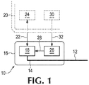
- Referring again to
FIG. 1 ,interconnect assembly 10 includes acable 12 having afirst end 14 and acable head 16 atfirst end 14 ofcable 12.Interconnect assembly 10 also includes awireless data transceiver 18 disposed incable head 16 to wirelessly communicate data to and fromdevice 20, as generally indicated by double-headed arrow 22 andwireless data transceiver 24 ofdevice 20. As can be seen inFIG. 1 ,wireless data transceiver 18 is coupled tofirst end 14 ofcable 12.Interconnect assembly 10 additionally includes awireless power coupler 26 disposed incable head 16 to wirelessly supply power fromdevice 20 towireless data transceiver 18, as generally indicated byarrow 28. As can also be seen inFIG. 1 ,device 20 includes apower supply 30 that wirelessly transmits power towireless power coupler 26, as generally indicated byarrow 32. - In this example,
cable head 16 provides a substantially fluid tight enclosure forwireless data transceiver 18 andwireless power coupler 26 to protect them from dirt, debris, moisture, etc. during use. Additionally,wireless data transceiver 18 andwireless power coupler 26 eliminate the issues, described above, associated with interconnect assemblies that utilize mechanical components. - An example of additional components or elements of
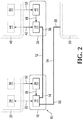
interconnect assembly 10 is shown inFIG. 2 . As can be seen inFIG. 2 ,interconnect assembly 10 may also include asecond cable head 34 atsecond end 36 ofcable 12 and a secondwireless data transceiver 38 disposed insecond cable head 34 to wirelessly communicate data to and fromsecond device 40, as generally indicated by double-headed arrow 42 andwireless data transceiver 44 ofsecond device 40. In this example, secondwireless data transceiver 38 is coupled tosecond end 36 ofcable 12.Interconnect assembly 10 additionally includes a secondwireless power coupler 46 disposed insecond cable head 34 to wirelessly supply power fromsecond device 40 towireless data transceiver 38, as generally indicated byarrow 48. As can also be seen inFIG. 2 ,second device 40 includes apower supply 50 that wirelessly transmits power to secondwireless power coupler 46, as generally indicated byarrow 52. - In this example,
second cable head 34 provides a substantially fluid tight enclosure for secondwireless data transceiver 38 and secondwireless power coupler 46 to protect them from dirt, debris, moisture, etc. during use. Additionally, secondwireless data transceiver 38 and secondwireless power coupler 46 eliminate the issues, described above, associated with interconnect assemblies that utilize mechanical components. - As can additionally be seen in
FIG. 2 ,interconnect assembly 10 may include asecond cable 54 having athird end 56 that is coupled towireless data transceiver 18.Second cable 54 also includes afourth end 58 to couple tothird device 60.Fourth end 58 may be coupled to a wireless data transceiver (not shown) ofthird device 60 or, for example, it may be directly connected to an input/output controller (also not shown) ofthird device 60. - An example of daisy
chaining interconnect assembly 10 is shown inFIG. 3 . As can be seen inFIG. 3 , in this example,interconnect assembly 10 includes a second cable 62 having athird end 64 and afourth end 66, and athird cable head 68 atthird end 64 of second cable 62.Interconnect assembly 10 also includes a thirdwireless data transceiver 70 disposed inthird cable head 68 to wireless communicate data to and fromsecond device 40, as generally indicated by double-headed arrow 72 andwireless data transceiver 74 ofsecond device 40, and a third wireless power coupler 76 disposed inthird cable head 68 to wirelessly supply power fromsecond device 40 to thirdwireless data transceiver 70, as generally indicated byarrow 78. In this example,second device 40 includes apower supply 80 that wirelessly transmits power to third wireless power coupler 76, as generally indicated byarrow 82. It is to be understood, however, that in other examples,power supply 50 ofsecond device 40 may be utilized to also wirelessly transmit power to third power coupler 76. - As can also be seen in
FIG. 3 ,interconnect assembly 10 includes afourth cable head 84 atfourth end 66 of second cable 62 and a fourthwireless data transceiver 86 disposed infourth cable head 84 to wirelessly communicate data to and fromthird device 88, as generally indicated by double-headed arrow 90 andwireless data transceiver 92 ofthird device 88.Interconnect assembly 10 additionally includes a fourthwireless power coupler 94 disposed infourth cable head 84 to wirelessly supply power fromthird device 88 to fourthwireless data transceiver 86, as generally indicated byarrow 96. As can additionally be seen inFIG. 3 ,device 88 includes apower supply 98 that wirelessly transmits power to fourthwireless power coupler 94, as generally indicated byarrow 100. - In this example, respective third and fourth cable heads 68 and 84 provide substantially fluid tight enclosures for third and fourth
wireless data transceivers wireless power couplers 76 and 94 to protect them from dirt, debris, moisture, etc. during use. Additionally, third and fourthwireless data transceivers wireless power couplers 76 and 94 eliminate the above-described issues associated with interconnect assemblies that utilize mechanical components. - As can further be seen in
FIG. 3 , this daisy chained arrangement ofinterconnect assembly 10 allows data to be wirelessly communicated between each ofdevices first device 20 andthird device 88,wireless data transceivers arrow 102, to provide a path or bridge for this communication. Although not shown inFIG. 3 , it is to be understood that any number of additional devices may wirelessly communicate using the illustrated daisy-chained interconnect assembly arrangement. Depending on the number of such additional devices, further cables, cable heads, wireless data transceivers, and/or wireless power couplers may be needed. - Another example of daisy chaining
interconnect assembly 10 is shown inFIG. 4 . As can be seen inFIG. 4 , in this example,interconnect assembly 10 includes asecond cable 104 having athird end 106 and afourth end 108, and athird cable head 110 atthird end 106 ofsecond cable 104.Interconnect assembly 10 also includes a thirdwireless data transceiver 112 disposed inthird cable head 110 to wirelessly communicate data to and from secondwireless data transceiver 38, as generally indicated by double-headedarrow 114, and a thirdwireless power coupler 116 disposed inthird cable head 110 to wirelessly supply power from secondwireless power coupler 46, as generally indicated byarrow 118, to thirdwireless data transceiver 112, as generally indicated byarrow 120. - As can also be seen in
FIG. 4 ,interconnect assembly 10 includes afourth cable head 122 atfourth end 108 ofsecond cable 104 and a fourthwireless data transceiver 124 disposed infourth cable head 122 to wirelessly communicate data to and fromthird device 88, as generally indicated by double-headedarrow 126 andwireless data transceiver 92 ofthird device 88.Interconnect assembly 10 additionally includes a fourthwireless power coupler 128 disposed infourth cable head 122 to wirelessly supply power fromthird device 88 to fourthwireless data transceiver 124, as generally indicated byarrow 130. As can additionally be seen inFIG. 4 ,device 88 includes apower supply 98 that wirelessly transmits power to fourthwireless power coupler 128, as generally indicated byarrow 132. - In this example, respective third and fourth cable heads 110 and 122 provide substantially fluid tight enclosures for third and fourth
wireless data transceivers wireless power couplers wireless data transceivers wireless power couplers - As can further be seen in
FIG. 4 , this daisy chained arrangement ofinterconnect assembly 10 allows data to be wirelessly communicated between each ofdevices FIG. 4 , it is to be understood that any number of additional devices may wirelessly communicate using the illustrated daisy-chained interconnect assembly arrangement. Depending on the number of such additional devices, further cables, cable heads, wireless data transceivers, and/or wireless power couplers may be needed. - In some examples, one or more of
wireless data transceivers interconnect assembly 10 may operate in the extremely high frequency (EHF) range. In other examples, one or more ofwireless data transceivers interconnect assembly 10 may operate substantially at sixty (60) gigahertz (GHz). In still other examples, one or more ofwireless data transceivers interconnect assembly 10 may operate substantially in an infrared frequency range. - An example of a type of connection for
second end 36 ofcable 12 ofinterconnect assembly 10 is illustrated inFIG. 5 . As can be seen inFIG. 5 ,interconnect assembly 10 further includes aconnector 134 atsecond end 36 ofcable 12 to couple to asecond device 136. More specifically,connector 134 is designed to plug into a socket, aperture oropening 138, as generally indicated byarrow 140.Connector 134 is also designed to unplug from socket, aperture oropening 138 by moving it in a direction generally indicated byarrow 142.Connector 134 may include any type configuration or design depending on the type of technology being used (e.g., Universal Serial Bus, Video Graphics Array, High Definition Multimedia Interface, IEEE 1394, etc.). - Another example of a type of connection for
second end 36 ofcable 12 ofinterconnect assembly 10 is illustrated inFIG. 6 . As can be seen inFIG. 6 , in this example,second end 36 ofcable 12 is hard wired to asecond device 144. More specifically,second end 36 is permanently retained or attached tosecond device 144 and is not intended to be removed by an end-user ofdevice 144. This type of connection may be established in a variety of different ways such as, for example, directly solderingsecond end 36 to an input/output controller ofsecond device 144 or through the use of a connector atsecond end 36 ofcable 12 that is held captive bysecond device 144. - An example illustrating some of the various types of technologies that may be used by
wireless power coupler 26 ofinterconnect assembly 10 is shown inFIG. 7 . As can be seen inFIG. 7 ,wireless power coupler 26 may utilize inductive 146, capacitive 148, optical 150, and/or radio frequency (RF) 152 coupling to wirelessly supply power fromdevice 20 towireless data transceiver 18. As can also be seen inFIG. 7 ,power supply 30 ofdevice 20 includes corresponding technology to wirelessly transmit power towireless power coupler 26, as generally indicated byarrow 32 andinductor 154,capacitor 156, light emitting diode (LED) 158, andradio transceiver 160. Although not shown inFIG. 7 , it is to be understood that one or more ofwireless power couplers corresponding power supply - An example illustrating an attachment and
alignment mechanism 162 in use withinterconnect assembly 10 is shown inFIG. 8 . Alignment andattachment mechanism 162 helps to facilitate connection ofcable head 16 todevice 20 as a result of the attraction betweenmagnets cable head 16 andmagnets device 20. Attachment andalignment mechanism 162 also facilitates wireless communication betweenwireless data transceiver 18 andwireless data transceiver 24 by helping to maintain their proper relative positions. Alignment andattachment mechanism 162 additionally facilitates wireless supply of power fromdevice 20 towireless power coupler 26 by helping to maintain proper relative positioning betweenpower supply 30 andwireless power coupler 26. - Although a pair of
magnets cable head 16 and a pair ofmagnets device 20 are shown in the example of attachment andalignment mechanism 162 ofFIG. 8 , it is to be understood that, in other examples, a different number may be used. For example, only one magnet incable head 16 and one magnet indevice 20. As another example, wherecable head 16 is made from a magnetic material, only one or more magnets may be needed indevice 20. As an additional example, wherebase 172 ofdevice 20 is made from a magnetic material, only one or more magnets may be needed incable head 16. Additionally, although not shown inFIG. 8 , it is to be understood that one or more of cable heads 34, 68, 84, 110, and 122 and/ordevices - Although several examples have been described and illustrated in detail, it is to be clearly understood that the same are intended by way of illustration and example only. These examples are not intended to be exhaustive or to limit the invention to the precise form or to the exemplary embodiments disclosed. Modifications and variations may well be apparent to those of ordinary skill in the art.
- Additionally, reference to an element in the singular is not intended to mean one and only one, unless explicitly so stated, but rather means one or more. Moreover, no element or component is intended to be dedicated to the public regardless of whether the element or component is explicitly recited in the following claims.
Claims (15)
- An interconnect assembly, comprising:a cable (12) including a first end (14);a cable head (16) at the first end (14) of the cable (12);a wireless data transceiver (18) disposed in the cable head (16) to wirelessly communicate data to and from a device (20) located at the first end (14) of the cable (12); characterised by a wireless power coupler (26) disposed in the cable head (16) to wirelessly supply power from the device (20) to the wireless data transceiver (18).
- The interconnect assembly of Claim 1, wherein the cable (12) includes a second end (36) and further comprising:a second cable head (34) at the second end (36) of the cable (12);a second wireless data transceiver (38) disposed in the second cable head (34) to wirelessly communicate data to and from a second device (40); anda second wireless power coupler (46) disposed in the second cable head (34) to wirelessly supply power from the second device (40) to the second wireless data transceiver (38).
- The interconnect assembly of Claim 2, further comprising a second cable (54) including a third end (56) coupled to the wireless data transceiver (18) and a fourth end (58) to couple to a third device (60).
- The interconnect assembly of Claim 2, further comprising:a second cable (62) including a third end (64) and a fourth end (66);a third cable head (68) at the third end (64) of the second cable (62);a third wireless data transceiver (70) disposed in the third cable head (68) to wirelessly communicate data to and from the second device (40);a third wireless power coupler (76) disposed in the third cable head (68) to wirelessly supply power from the second device (40) to the third wireless data transceiver (70);a fourth cable head (84) at the fourth end (66) of the second cable (62);a fourth wireless data transceiver (86) disposed in the fourth cable head (84) to wirelessly communicate data to and from a third device (88); anda fourth wireless power coupler (94) disposed in the fourth cable head (84) to wirelessly supply power from the third device (88) to the fourth wireless data transceiver (86).
- The interconnect assembly of Claim 2, further comprising:a second cable (104) including a third end (106) and a fourth end (108);a third cable head (110) at the third end (106) of the second cable (104);a third wireless data transceiver (112) disposed in the third cable head (110) to wirelessly communicate data to and from the second wireless data transceiver (38);a third wireless power coupler (116) disposed in the third cable head (110) to wirelessly supply power from the second wireless power coupler (46) to the third wireless data transceiver (112);a fourth cable head (122) at the fourth end (108) of the second cable (104);a fourth wireless data transceiver (124) disposed in the fourth cable head (122) to wirelessly communicate data to and from a third device (88); anda fourth wireless power coupler (128) disposed in the fourth cable head (122) to wirelessly supply power from the third device (88) to the fourth wireless data transceiver (124).
- The interconnect assembly of Claim 1, wherein the wireless data transceiver (18) operates in an extremely high frequency (EHF) range.
- The interconnect assembly of Claim 1, wherein the wireless data transceiver (18) operates substantially at sixty (60) gigahertz (GHz).
- The interconnect assembly of Claim 1, wherein the wireless data transceiver (18) operates substantially in an infrared frequency range.
- The interconnect assembly of Claim 1, wherein the cable (12) includes a second end (36) and further comprising a connector (134) at the second end (36) of the cable (12) to couple to a second device (136).
- The interconnect assembly of Claim 1, wherein the cable (12) includes a second end (36), and further wherein the second end (36) is hard wired to a second device (144).
- The interconnect assembly of Claim 1, wherein the wireless power coupler (26) utilizes at least one of inductive, capacitive, optical, and radio frequency coupling to wirelessly supply power from the device (20) to the wireless data transceiver (18).
- The interconnect assembly of Claim 1, further comprising an attachment mechanism (162) to facilitate connection of the cable head (16) to the device (20).
- The interconnect assembly of Claim 12, wherein the attachment mechanism (162) includes a magnet (164, 166, 168, 170) in at least one of the cable head (16) and the device (20).
- The interconnect assembly of Claim 1, further comprising an alignment mechanism (162) to facilitate at least one of wireless communication of data to and from the device (20) and wireless supply of power from the device (20) to the wireless power coupler (26).
- The interconnect assembly of Claim 14, wherein the alignment mechanism (162) includes a magnet (164, 166, 168, 170) in at least one of the cable head (16) and the device (20).
Applications Claiming Priority (1)
| Application Number | Priority Date | Filing Date | Title |
|---|---|---|---|
| PCT/US2013/032877 WO2014149032A1 (en) | 2013-03-19 | 2013-03-19 | Interconnect assembly |
Publications (3)
| Publication Number | Publication Date |
|---|---|
| EP2976873A1 EP2976873A1 (en) | 2016-01-27 |
| EP2976873A4 EP2976873A4 (en) | 2016-11-09 |
| EP2976873B1 true EP2976873B1 (en) | 2017-11-01 |
Family
ID=51580535
Family Applications (1)
| Application Number | Title | Priority Date | Filing Date |
|---|---|---|---|
| EP13878590.2A Not-in-force EP2976873B1 (en) | 2013-03-19 | 2013-03-19 | Interconnect assembly |
Country Status (4)
| Country | Link |
|---|---|
| US (1) | US20160132457A1 (en) |
| EP (1) | EP2976873B1 (en) |
| CN (1) | CN105052117A (en) |
| WO (1) | WO2014149032A1 (en) |
Families Citing this family (1)
| Publication number | Priority date | Publication date | Assignee | Title |
|---|---|---|---|---|
| TWI632757B (en) * | 2015-09-30 | 2018-08-11 | 美商蘋果公司 | Apparatus for magnetic charging and optical data transfer |
Family Cites Families (35)
| Publication number | Priority date | Publication date | Assignee | Title |
|---|---|---|---|---|
| US6131125A (en) * | 1997-11-14 | 2000-10-10 | Kawasaki Lsi U.S.A., Inc. | Plug-and-play data cable with protocol translation |
| JP3812787B2 (en) * | 1997-11-20 | 2006-08-23 | 株式会社日立国際電気 | Optical conversion repeater amplification system |
| US6327476B1 (en) * | 1998-06-30 | 2001-12-04 | Conexant Systems, Inc. | System and method for wireless voice and computer communications using a wireless link to a public telephone network |
| US7149474B1 (en) * | 1999-11-02 | 2006-12-12 | Broadcom Corporation | Wireless cable replacement system |
| US6326926B1 (en) * | 2000-05-18 | 2001-12-04 | Telxon Corporation | Method of operating a wireless and a short-range wireless connection in the same frequency |
| US7096164B1 (en) * | 2001-02-21 | 2006-08-22 | Intangi, Inc. | Automatic design and sale of complex multi-vendor electronic and mechanical systems |
| US6801755B2 (en) * | 2001-03-29 | 2004-10-05 | Intol Corporation | Method and apparatus for providing a radio module for a computer system |
| US6870475B2 (en) * | 2002-07-08 | 2005-03-22 | Draeger Medical Systems Inc. | Electrically isolated power and data coupling system suitable for portable and other equipment |
| GB0229141D0 (en) * | 2002-12-16 | 2003-01-15 | Splashpower Ltd | Improvements relating to contact-less power transfer |
| US7671803B2 (en) * | 2003-07-25 | 2010-03-02 | Hewlett-Packard Development Company, L.P. | Wireless communication system |
| KR100639964B1 (en) * | 2004-09-30 | 2006-11-01 | 한국전자통신연구원 | Contactless USB reader and contactless USB card apparatus |
| JP2006295672A (en) * | 2005-04-13 | 2006-10-26 | Nec Engineering Ltd | Noncontact communication cable, and noncontact data communication apparatus |
| WO2007102803A1 (en) * | 2006-03-06 | 2007-09-13 | Razer Usa Ltd. | Computer input device with wireless/wired modes |
| US8472767B2 (en) * | 2006-05-19 | 2013-06-25 | Corning Cable Systems Llc | Fiber optic cable and fiber optic cable assembly for wireless access |
| US7772802B2 (en) * | 2007-03-01 | 2010-08-10 | Eastman Kodak Company | Charging display system |
| US7793121B2 (en) * | 2007-03-01 | 2010-09-07 | Eastman Kodak Company | Charging display system |
| US7963773B2 (en) * | 2007-12-24 | 2011-06-21 | Craig Palli | Magnetic and locking cable connectors |
| KR100939669B1 (en) * | 2008-01-02 | 2010-02-03 | 한국과학기술원 | An Apparatus and Method for wireless data exchange using USB |
| US20100159741A1 (en) * | 2008-12-18 | 2010-06-24 | Wayne Philip Rothbaum | Magnetic Cord Management System |
| US8326221B2 (en) * | 2009-02-09 | 2012-12-04 | Apple Inc. | Portable electronic device with proximity-based content synchronization |
| CN101814749B (en) * | 2009-02-20 | 2013-10-09 | 鸿富锦精密工业(深圳)有限公司 | Charging device |
| TWI578142B (en) * | 2009-07-24 | 2017-04-11 | 通路實業集團國際公司 | Power supply |
| US20110115429A1 (en) * | 2009-11-13 | 2011-05-19 | Nokia Corporation | Wireless Charging Adapter Compatible With Wall Charger And Wireless Charging Plate |
| US8577195B2 (en) * | 2009-11-19 | 2013-11-05 | Apple Inc. | Interface accessories with optical and electrical paths |
| US8484395B2 (en) * | 2010-01-27 | 2013-07-09 | Broadcom Corporation | System and method for dynamically configuring processing resources and memory resources of wireless-enabled components |
| US8432261B2 (en) * | 2010-02-26 | 2013-04-30 | GM Global Technology Operations LLC | Simplified device pairing employing near field communication tags |
| KR20110138881A (en) * | 2010-06-22 | 2011-12-28 | 삼성전기주식회사 | Apparatus for wire/wireless communication and wireless communication system using wire network |
| US8442588B2 (en) * | 2010-09-08 | 2013-05-14 | Apple Inc. | Systems having cables with wireless communications capabilities |
| JP5789790B2 (en) * | 2010-09-10 | 2015-10-07 | パナソニックIpマネジメント株式会社 | Power transmission device and wireless power transmission system |
| US8774577B2 (en) * | 2010-12-07 | 2014-07-08 | Corning Cable Systems Llc | Optical couplings having coded magnetic arrays and devices incorporating the same |
| US9021164B2 (en) * | 2012-08-03 | 2015-04-28 | Dell Products L.P. | Near field communication mimic device and method of use |
| US9457197B2 (en) * | 2012-05-08 | 2016-10-04 | Physio-Control, Inc. | Utility module system |
| SG195411A1 (en) * | 2012-05-24 | 2013-12-30 | Sony Corp | Connecting multiple electronic devices |
| US8757893B1 (en) * | 2013-01-29 | 2014-06-24 | Corning Cable Systems Llc | Optical connector assemblies having alignment components |
| US9735514B2 (en) * | 2015-03-19 | 2017-08-15 | Mellanox Technologies, Ltd. | Connector module with internal wireless communication device |
-
2013
- 2013-03-19 EP EP13878590.2A patent/EP2976873B1/en not_active Not-in-force
- 2013-03-19 WO PCT/US2013/032877 patent/WO2014149032A1/en active Application Filing
- 2013-03-19 US US14/770,807 patent/US20160132457A1/en not_active Abandoned
- 2013-03-19 CN CN201380074916.5A patent/CN105052117A/en active Pending
Non-Patent Citations (1)
| Title |
|---|
| None * |
Also Published As
| Publication number | Publication date |
|---|---|
| US20160132457A1 (en) | 2016-05-12 |
| EP2976873A4 (en) | 2016-11-09 |
| EP2976873A1 (en) | 2016-01-27 |
| CN105052117A (en) | 2015-11-11 |
| WO2014149032A1 (en) | 2014-09-25 |
Similar Documents
| Publication | Publication Date | Title |
|---|---|---|
| US9538313B2 (en) | Apparatus, system and method of docking a mobile device with wireless connector | |
| US11445626B2 (en) | Power outlet module including USB plug in location other than outlet face | |
| US20190215605A1 (en) | Contactless audio adapter, and methods | |
| CN102027647B (en) | Connector arrangement | |
| US20160211889A1 (en) | Stackable, magnetically-retained connector interface | |
| US8442588B2 (en) | Systems having cables with wireless communications capabilities | |
| US20150349537A1 (en) | Scalable antenna system | |
| KR20150016211A (en) | Contactless replacement for cabled standards-based interfaces | |
| US9128248B2 (en) | Optical transceiver interface with C-shaped planar alignment and securing | |
| US9824057B2 (en) | Integrated circuit for relying signal over USB connector with signal having notch at frequency of wireless band with transfer rate higher than frequency of USB high-speed interconnect | |
| CN110771053B (en) | Connector attached to cable and cable for use in power-hungry applications | |
| EP2976873B1 (en) | Interconnect assembly | |
| EP2851721A1 (en) | Wireless flat optical connector | |
| EP2626959B1 (en) | Integrated electric connector | |
| US10170851B2 (en) | Connector with a wireless coupler | |
| US20160006727A1 (en) | Interconnect Assembly | |
| US9728907B2 (en) | Interconnect assembly | |
| KR102465607B1 (en) | Detachable Cable | |
| US11962115B2 (en) | Expansion device with power and data connections | |
| CN209151360U (en) | A kind of accessory of mobile device | |
| US20130029534A1 (en) | Connector with wireless connectivity | |
| CN105633748A (en) | Special peripheral communication cable connection device for computer data transmission | |
| CN202838646U (en) | Wireless control system applied to portable electronic device | |
| CN103377543A (en) | Wireless control system applied to portable electronic device | |
| US8070523B1 (en) | Transmission cable for a computer and an electronic device |
Legal Events
| Date | Code | Title | Description |
|---|---|---|---|
| PUAI | Public reference made under article 153(3) epc to a published international application that has entered the european phase |
Free format text: ORIGINAL CODE: 0009012 |
|
| 17P | Request for examination filed |
Effective date: 20150908 |
|
| AK | Designated contracting states |
Kind code of ref document: A1 Designated state(s): AL AT BE BG CH CY CZ DE DK EE ES FI FR GB GR HR HU IE IS IT LI LT LU LV MC MK MT NL NO PL PT RO RS SE SI SK SM TR |
|
| AX | Request for extension of the european patent |
Extension state: BA ME |
|
| DAX | Request for extension of the european patent (deleted) | ||
| A4 | Supplementary search report drawn up and despatched |
Effective date: 20161007 |
|
| RIC1 | Information provided on ipc code assigned before grant |
Ipc: G06F 13/40 20060101ALI20161003BHEP Ipc: H04L 29/12 20060101AFI20161003BHEP Ipc: G06F 13/42 20060101ALI20161003BHEP Ipc: G06F 13/14 20060101ALI20161003BHEP |
|
| REG | Reference to a national code |
Ref country code: DE Ref legal event code: R079 Ref document number: 602013028967 Country of ref document: DE Free format text: PREVIOUS MAIN CLASS: H04L0029120000 Ipc: G06F0013380000 |
|
| GRAP | Despatch of communication of intention to grant a patent |
Free format text: ORIGINAL CODE: EPIDOSNIGR1 |
|
| RIC1 | Information provided on ipc code assigned before grant |
Ipc: G06F 13/40 20060101ALI20170719BHEP Ipc: G06F 13/38 20060101AFI20170719BHEP |
|
| INTG | Intention to grant announced |
Effective date: 20170809 |
|
| GRAS | Grant fee paid |
Free format text: ORIGINAL CODE: EPIDOSNIGR3 |
|
| GRAA | (expected) grant |
Free format text: ORIGINAL CODE: 0009210 |
|
| AK | Designated contracting states |
Kind code of ref document: B1 Designated state(s): AL AT BE BG CH CY CZ DE DK EE ES FI FR GB GR HR HU IE IS IT LI LT LU LV MC MK MT NL NO PL PT RO RS SE SI SK SM TR |
|
| REG | Reference to a national code |
Ref country code: GB Ref legal event code: FG4D |
|
| REG | Reference to a national code |
Ref country code: CH Ref legal event code: EP Ref country code: AT Ref legal event code: REF Ref document number: 942680 Country of ref document: AT Kind code of ref document: T Effective date: 20171115 |
|
| REG | Reference to a national code |
Ref country code: IE Ref legal event code: FG4D |
|
| REG | Reference to a national code |
Ref country code: DE Ref legal event code: R096 Ref document number: 602013028967 Country of ref document: DE |
|
| REG | Reference to a national code |
Ref country code: NL Ref legal event code: MP Effective date: 20171101 |
|
| REG | Reference to a national code |
Ref country code: LT Ref legal event code: MG4D |
|
| REG | Reference to a national code |
Ref country code: AT Ref legal event code: MK05 Ref document number: 942680 Country of ref document: AT Kind code of ref document: T Effective date: 20171101 |
|
| PG25 | Lapsed in a contracting state [announced via postgrant information from national office to epo] |
Ref country code: FI Free format text: LAPSE BECAUSE OF FAILURE TO SUBMIT A TRANSLATION OF THE DESCRIPTION OR TO PAY THE FEE WITHIN THE PRESCRIBED TIME-LIMIT Effective date: 20171101 Ref country code: LT Free format text: LAPSE BECAUSE OF FAILURE TO SUBMIT A TRANSLATION OF THE DESCRIPTION OR TO PAY THE FEE WITHIN THE PRESCRIBED TIME-LIMIT Effective date: 20171101 Ref country code: SE Free format text: LAPSE BECAUSE OF FAILURE TO SUBMIT A TRANSLATION OF THE DESCRIPTION OR TO PAY THE FEE WITHIN THE PRESCRIBED TIME-LIMIT Effective date: 20171101 Ref country code: NO Free format text: LAPSE BECAUSE OF FAILURE TO SUBMIT A TRANSLATION OF THE DESCRIPTION OR TO PAY THE FEE WITHIN THE PRESCRIBED TIME-LIMIT Effective date: 20180201 Ref country code: ES Free format text: LAPSE BECAUSE OF FAILURE TO SUBMIT A TRANSLATION OF THE DESCRIPTION OR TO PAY THE FEE WITHIN THE PRESCRIBED TIME-LIMIT Effective date: 20171101 Ref country code: NL Free format text: LAPSE BECAUSE OF FAILURE TO SUBMIT A TRANSLATION OF THE DESCRIPTION OR TO PAY THE FEE WITHIN THE PRESCRIBED TIME-LIMIT Effective date: 20171101 |
|
| PG25 | Lapsed in a contracting state [announced via postgrant information from national office to epo] |
Ref country code: GR Free format text: LAPSE BECAUSE OF FAILURE TO SUBMIT A TRANSLATION OF THE DESCRIPTION OR TO PAY THE FEE WITHIN THE PRESCRIBED TIME-LIMIT Effective date: 20180202 Ref country code: LV Free format text: LAPSE BECAUSE OF FAILURE TO SUBMIT A TRANSLATION OF THE DESCRIPTION OR TO PAY THE FEE WITHIN THE PRESCRIBED TIME-LIMIT Effective date: 20171101 Ref country code: BG Free format text: LAPSE BECAUSE OF FAILURE TO SUBMIT A TRANSLATION OF THE DESCRIPTION OR TO PAY THE FEE WITHIN THE PRESCRIBED TIME-LIMIT Effective date: 20180201 Ref country code: AT Free format text: LAPSE BECAUSE OF FAILURE TO SUBMIT A TRANSLATION OF THE DESCRIPTION OR TO PAY THE FEE WITHIN THE PRESCRIBED TIME-LIMIT Effective date: 20171101 Ref country code: HR Free format text: LAPSE BECAUSE OF FAILURE TO SUBMIT A TRANSLATION OF THE DESCRIPTION OR TO PAY THE FEE WITHIN THE PRESCRIBED TIME-LIMIT Effective date: 20171101 Ref country code: IS Free format text: LAPSE BECAUSE OF FAILURE TO SUBMIT A TRANSLATION OF THE DESCRIPTION OR TO PAY THE FEE WITHIN THE PRESCRIBED TIME-LIMIT Effective date: 20180301 Ref country code: RS Free format text: LAPSE BECAUSE OF FAILURE TO SUBMIT A TRANSLATION OF THE DESCRIPTION OR TO PAY THE FEE WITHIN THE PRESCRIBED TIME-LIMIT Effective date: 20171101 |
|
| PG25 | Lapsed in a contracting state [announced via postgrant information from national office to epo] |
Ref country code: CZ Free format text: LAPSE BECAUSE OF FAILURE TO SUBMIT A TRANSLATION OF THE DESCRIPTION OR TO PAY THE FEE WITHIN THE PRESCRIBED TIME-LIMIT Effective date: 20171101 Ref country code: EE Free format text: LAPSE BECAUSE OF FAILURE TO SUBMIT A TRANSLATION OF THE DESCRIPTION OR TO PAY THE FEE WITHIN THE PRESCRIBED TIME-LIMIT Effective date: 20171101 Ref country code: CY Free format text: LAPSE BECAUSE OF FAILURE TO SUBMIT A TRANSLATION OF THE DESCRIPTION OR TO PAY THE FEE WITHIN THE PRESCRIBED TIME-LIMIT Effective date: 20171101 Ref country code: SK Free format text: LAPSE BECAUSE OF FAILURE TO SUBMIT A TRANSLATION OF THE DESCRIPTION OR TO PAY THE FEE WITHIN THE PRESCRIBED TIME-LIMIT Effective date: 20171101 Ref country code: DK Free format text: LAPSE BECAUSE OF FAILURE TO SUBMIT A TRANSLATION OF THE DESCRIPTION OR TO PAY THE FEE WITHIN THE PRESCRIBED TIME-LIMIT Effective date: 20171101 |
|
| REG | Reference to a national code |
Ref country code: DE Ref legal event code: R097 Ref document number: 602013028967 Country of ref document: DE |
|
| PG25 | Lapsed in a contracting state [announced via postgrant information from national office to epo] |
Ref country code: RO Free format text: LAPSE BECAUSE OF FAILURE TO SUBMIT A TRANSLATION OF THE DESCRIPTION OR TO PAY THE FEE WITHIN THE PRESCRIBED TIME-LIMIT Effective date: 20171101 Ref country code: PL Free format text: LAPSE BECAUSE OF FAILURE TO SUBMIT A TRANSLATION OF THE DESCRIPTION OR TO PAY THE FEE WITHIN THE PRESCRIBED TIME-LIMIT Effective date: 20171101 Ref country code: SM Free format text: LAPSE BECAUSE OF FAILURE TO SUBMIT A TRANSLATION OF THE DESCRIPTION OR TO PAY THE FEE WITHIN THE PRESCRIBED TIME-LIMIT Effective date: 20171101 Ref country code: IT Free format text: LAPSE BECAUSE OF FAILURE TO SUBMIT A TRANSLATION OF THE DESCRIPTION OR TO PAY THE FEE WITHIN THE PRESCRIBED TIME-LIMIT Effective date: 20171101 |
|
| PLBE | No opposition filed within time limit |
Free format text: ORIGINAL CODE: 0009261 |
|
| STAA | Information on the status of an ep patent application or granted ep patent |
Free format text: STATUS: NO OPPOSITION FILED WITHIN TIME LIMIT |
|
| REG | Reference to a national code |
Ref country code: DE Ref legal event code: R119 Ref document number: 602013028967 Country of ref document: DE |
|
| 26N | No opposition filed |
Effective date: 20180802 |
|
| REG | Reference to a national code |
Ref country code: CH Ref legal event code: PL |
|
| GBPC | Gb: european patent ceased through non-payment of renewal fee |
Effective date: 20180319 |
|
| PG25 | Lapsed in a contracting state [announced via postgrant information from national office to epo] |
Ref country code: SI Free format text: LAPSE BECAUSE OF FAILURE TO SUBMIT A TRANSLATION OF THE DESCRIPTION OR TO PAY THE FEE WITHIN THE PRESCRIBED TIME-LIMIT Effective date: 20171101 Ref country code: MC Free format text: LAPSE BECAUSE OF FAILURE TO SUBMIT A TRANSLATION OF THE DESCRIPTION OR TO PAY THE FEE WITHIN THE PRESCRIBED TIME-LIMIT Effective date: 20171101 |
|
| REG | Reference to a national code |
Ref country code: BE Ref legal event code: MM Effective date: 20180331 |
|
| REG | Reference to a national code |
Ref country code: IE Ref legal event code: MM4A |
|
| PG25 | Lapsed in a contracting state [announced via postgrant information from national office to epo] |
Ref country code: LU Free format text: LAPSE BECAUSE OF NON-PAYMENT OF DUE FEES Effective date: 20180319 |
|
| PG25 | Lapsed in a contracting state [announced via postgrant information from national office to epo] |
Ref country code: IE Free format text: LAPSE BECAUSE OF NON-PAYMENT OF DUE FEES Effective date: 20180319 Ref country code: DE Free format text: LAPSE BECAUSE OF NON-PAYMENT OF DUE FEES Effective date: 20181002 |
|
| PG25 | Lapsed in a contracting state [announced via postgrant information from national office to epo] |
Ref country code: GB Free format text: LAPSE BECAUSE OF NON-PAYMENT OF DUE FEES Effective date: 20180319 Ref country code: BE Free format text: LAPSE BECAUSE OF NON-PAYMENT OF DUE FEES Effective date: 20180331 Ref country code: CH Free format text: LAPSE BECAUSE OF NON-PAYMENT OF DUE FEES Effective date: 20180331 Ref country code: LI Free format text: LAPSE BECAUSE OF NON-PAYMENT OF DUE FEES Effective date: 20180331 |
|
| PG25 | Lapsed in a contracting state [announced via postgrant information from national office to epo] |
Ref country code: FR Free format text: LAPSE BECAUSE OF NON-PAYMENT OF DUE FEES Effective date: 20180331 |
|
| PG25 | Lapsed in a contracting state [announced via postgrant information from national office to epo] |
Ref country code: MT Free format text: LAPSE BECAUSE OF NON-PAYMENT OF DUE FEES Effective date: 20180319 |
|
| PG25 | Lapsed in a contracting state [announced via postgrant information from national office to epo] |
Ref country code: TR Free format text: LAPSE BECAUSE OF FAILURE TO SUBMIT A TRANSLATION OF THE DESCRIPTION OR TO PAY THE FEE WITHIN THE PRESCRIBED TIME-LIMIT Effective date: 20171101 |
|
| PG25 | Lapsed in a contracting state [announced via postgrant information from national office to epo] |
Ref country code: PT Free format text: LAPSE BECAUSE OF FAILURE TO SUBMIT A TRANSLATION OF THE DESCRIPTION OR TO PAY THE FEE WITHIN THE PRESCRIBED TIME-LIMIT Effective date: 20171101 |
|
| PG25 | Lapsed in a contracting state [announced via postgrant information from national office to epo] |
Ref country code: MK Free format text: LAPSE BECAUSE OF NON-PAYMENT OF DUE FEES Effective date: 20171101 Ref country code: HU Free format text: LAPSE BECAUSE OF FAILURE TO SUBMIT A TRANSLATION OF THE DESCRIPTION OR TO PAY THE FEE WITHIN THE PRESCRIBED TIME-LIMIT; INVALID AB INITIO Effective date: 20130319 |
|
| PG25 | Lapsed in a contracting state [announced via postgrant information from national office to epo] |
Ref country code: AL Free format text: LAPSE BECAUSE OF FAILURE TO SUBMIT A TRANSLATION OF THE DESCRIPTION OR TO PAY THE FEE WITHIN THE PRESCRIBED TIME-LIMIT Effective date: 20171101 |