EP2969397B1 - Power tool operation recording and playback - Google Patents
Power tool operation recording and playback Download PDFInfo
- Publication number
- EP2969397B1 EP2969397B1 EP14764096.5A EP14764096A EP2969397B1 EP 2969397 B1 EP2969397 B1 EP 2969397B1 EP 14764096 A EP14764096 A EP 14764096A EP 2969397 B1 EP2969397 B1 EP 2969397B1
- Authority
- EP
- European Patent Office
- Prior art keywords
- mode
- motor
- trigger
- controller
- power tool
- Prior art date
- Legal status (The legal status is an assumption and is not a legal conclusion. Google has not performed a legal analysis and makes no representation as to the accuracy of the status listed.)
- Active
Links
- 230000004913 activation Effects 0.000 claims description 74
- 238000000034 method Methods 0.000 claims description 14
- 238000001994 activation Methods 0.000 claims 15
- 230000007246 mechanism Effects 0.000 description 28
- 238000010586 diagram Methods 0.000 description 18
- 238000004891 communication Methods 0.000 description 6
- 230000000994 depressogenic effect Effects 0.000 description 5
- 230000007935 neutral effect Effects 0.000 description 4
- KJBDZJFSYQUNJT-UHFFFAOYSA-N 1,2,3,5-tetrachloro-4-(2,3,5-trichlorophenyl)benzene Chemical compound ClC1=CC(Cl)=C(Cl)C(C=2C(=C(Cl)C(Cl)=CC=2Cl)Cl)=C1 KJBDZJFSYQUNJT-UHFFFAOYSA-N 0.000 description 3
- PXHVJJICTQNCMI-UHFFFAOYSA-N nickel Substances [Ni] PXHVJJICTQNCMI-UHFFFAOYSA-N 0.000 description 3
- HBBGRARXTFLTSG-UHFFFAOYSA-N Lithium ion Chemical compound [Li+] HBBGRARXTFLTSG-UHFFFAOYSA-N 0.000 description 2
- 238000010276 construction Methods 0.000 description 2
- 238000013500 data storage Methods 0.000 description 2
- -1 for example Chemical compound 0.000 description 2
- 229910001416 lithium ion Inorganic materials 0.000 description 2
- 229910052759 nickel Inorganic materials 0.000 description 2
- 230000001360 synchronised effect Effects 0.000 description 2
- WHXSMMKQMYFTQS-UHFFFAOYSA-N Lithium Chemical compound [Li] WHXSMMKQMYFTQS-UHFFFAOYSA-N 0.000 description 1
- 229910000831 Steel Inorganic materials 0.000 description 1
- 230000005540 biological transmission Effects 0.000 description 1
- 230000004397 blinking Effects 0.000 description 1
- OJIJEKBXJYRIBZ-UHFFFAOYSA-N cadmium nickel Chemical compound [Ni].[Cd] OJIJEKBXJYRIBZ-UHFFFAOYSA-N 0.000 description 1
- 230000008859 change Effects 0.000 description 1
- 230000006698 induction Effects 0.000 description 1
- 229910052744 lithium Inorganic materials 0.000 description 1
- 239000000463 material Substances 0.000 description 1
- 229910052751 metal Inorganic materials 0.000 description 1
- 239000002184 metal Substances 0.000 description 1
- 229910052987 metal hydride Inorganic materials 0.000 description 1
- 230000003287 optical effect Effects 0.000 description 1
- 230000010355 oscillation Effects 0.000 description 1
- 230000008569 process Effects 0.000 description 1
- 230000007420 reactivation Effects 0.000 description 1
- 239000010959 steel Substances 0.000 description 1
- 230000000007 visual effect Effects 0.000 description 1
Images


Classifications
-
- B—PERFORMING OPERATIONS; TRANSPORTING
- B25—HAND TOOLS; PORTABLE POWER-DRIVEN TOOLS; MANIPULATORS
- B25F—COMBINATION OR MULTI-PURPOSE TOOLS NOT OTHERWISE PROVIDED FOR; DETAILS OR COMPONENTS OF PORTABLE POWER-DRIVEN TOOLS NOT PARTICULARLY RELATED TO THE OPERATIONS PERFORMED AND NOT OTHERWISE PROVIDED FOR
- B25F5/00—Details or components of portable power-driven tools not particularly related to the operations performed and not otherwise provided for
-
- B—PERFORMING OPERATIONS; TRANSPORTING
- B23—MACHINE TOOLS; METAL-WORKING NOT OTHERWISE PROVIDED FOR
- B23B—TURNING; BORING
- B23B45/00—Hand-held or like portable drilling machines, e.g. drill guns; Equipment therefor
- B23B45/02—Hand-held or like portable drilling machines, e.g. drill guns; Equipment therefor driven by electric power
-
- B—PERFORMING OPERATIONS; TRANSPORTING
- B25—HAND TOOLS; PORTABLE POWER-DRIVEN TOOLS; MANIPULATORS
- B25B—TOOLS OR BENCH DEVICES NOT OTHERWISE PROVIDED FOR, FOR FASTENING, CONNECTING, DISENGAGING OR HOLDING
- B25B21/00—Portable power-driven screw or nut setting or loosening tools; Attachments for drilling apparatus serving the same purpose
Description
- The present application claims priority to
U.S. Provisional Patent Application No. 61/788,510, filed on March 15, 2013 - The present invention relates generally to power tools, such as power drills or impact drivers.
CH 393 489 US 2012/0318545 describes a power-operated hand-held power tool, in particular a power tool comprising an oscillation drive for driving a tool in an oscillating manner, comprising at least one sensor for detecting vibrations and comprising a controller which is coupled to the at least one sensor to control at least one operating parameter of the power tool according to an output signal of the at least one sensor. The controller is configured to evaluate the output signal of the at least on sensor and preferably to compare it with stored characteristic values for the vibrations so as to control at least one operating parameter of the power tool according to said comparison. - In one embodiment, the invention provides a power tool including a tool housing defining a cavity, a motor positioned within the cavity, a trigger, a mode selector switch, and a controller. The trigger is coupled to the tool housing and configured to output an activation signal based on a user input. The mode selector switch is configured to receive a user mode selection, which indicates an operating mode selected from the group of a recording mode, a normal operating mode, and a playback mode. The controller is coupled to the trigger, the mode selector switch, and the motor. The controller is configured to receive a mode selection signal from the mode selector switch that is indicative of the user mode selection for the power tool. The controller is further configured to enter the recording mode when the user mode selection indicates the recording mode, and to record a motor parameter while the power tool is in the recording mode and the motor is operating to generate a recorded motor parameter. The controller is further configured to enter the playback mode when the user mode selection indicates the playback mode, and to operate the motor based on the recorded motor parameter upon receiving the activation signal from the trigger while the power tool is in the playback mode.
- In another embodiment, the invention provides a method of operating a power tool including a motor, a mode selector switch, a trigger, and a controller. The method includes receiving, by the mode selector switch, a user mode selection indicating an operating mode for the power tool. The operating mode is selected from the group of a recording mode, a playback mode, and a normal operating mode. The method further includes entering, by the controller, the recording mode when the user mode selection indicates the recording mode, and recording, by the controller, a motor parameter while the power tool is in the recording mode and the motor is operating to generate a recorded motor parameter. The method further includes entering, by the controller, the playback mode when the user mode selection indicates the playback mode, and receiving, by the controller, an activation signal from the trigger. The method further includes executing, by the controller, the recorded motor parameter to operate the motor based on the recorded motor parameter upon receipt of the activation signal while the power tool is in the playback mode.
- Other aspects of the invention will become apparent by consideration of the detailed description and accompanying drawings.
-
-
FIG. 1 is a perspective view of a tool according to one embodiment of the invention. -
FIG. 2 is a side view of the tool shown inFIG. 1 with a portion of a tool housing removed. -
FIG. 3 illustrates a direction switch of the tool shown inFIG. 1 in a FORWARD position. -
FIG. 4 illustrates the direction switch of the tool shown inFIG. 1 in a REVERSE position. -
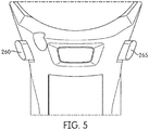
FIG. 5 illustrates the direction switch of the tool shown inFIG. 1 in a NEUTRAL position. -
FIG. 6 illustrates a speed selector switch of the tool shown inFIG. 1 . -
FIG. 7 illustrates a block diagram of the speed selector switch shown inFIG. 6 . -
FIG. 8 is an electrical schematic diagram of the tool shown inFIG. 1 , and including a controller. -
FIG. 9 is an operational schematic diagram of the tool shown inFIG. 1 . -
FIG. 10 is an operational schematic diagram of the tool shown inFIG. 1 . -
FIG. 11 an operational schematic diagram of the tool shown inFIG. 1 . -
FIG. 12 an operational schematic diagram of the tool shown inFIG. 1 . -
FIG. 13 an operational schematic diagram of the tool shown inFIG. 1 . -
FIG. 14 an operational schematic diagram of the tool shown inFIG. 1 . -
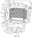
FIG. 15 is a perspective view of the tool shown inFIG. 1 with the tool housing removed. -
FIG. 16 is a perspective view of the tool shown inFIG. 1 with a motor and a portion of the tool housing removed. -
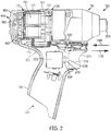
FIG. 17 is a perspective view of a tool according to another embodiment of the invention. -
FIG. 18 is a side view of the tool shown inFIG. 17 . - Before any embodiments of the invention are explained in detail, it is to be understood that the invention is not limited in its application to the details of construction and the arrangement of components set forth in the following description or illustrated in the following drawings.
- In one embodiment, the invention provides a power tool that includes a tool housing defining a cavity and a pocket formed in a wall of the tool housing. A motor is positioned within the cavity, and a trigger mechanism is moveably coupled to the tool housing. A mode selector switch is positioned within the pocket, the mode selector switch including a plurality of speed indicators and a push-button operable to receive a user mode selection. The mode selector switch is operable to allow the power tool to be operated in one of a recording mode, a playback mode, and a normal operating mode based on the user mode selection, and the speed indicators indicate the user mode selection. The power tool further includes a controller operable to receive the user mode signal from the speed selector switch, the user mode signal indicative of a selected user mode, receive an activation signal from the trigger switch, record operation of a motor or other parameter during the recording mode upon receiving the activation signal, operate the motor during the playback mode based on the recorded motor operation upon receiving the activation signal, or operate the motor according to the activation signal during the normal operating mode. While the embodiments described hereinbelow refer to motor parameter recording, embodiments of the invention contemplate the recording and playback of other operating parameters as well that result from activation of the trigger, and references to "motor parameter" are not intended to be limiting to only parameters directly related to operation of the motor.
- In another embodiment, the invention provides a power tool including a tool housing defining a cavity, a motor positioned within the cavity, and a trigger mechanism moveably coupled to the tool housing. A usage mode selector switch is coupled to the tool housing, and the tool includes a plurality of usage mode indicators. The usage mode selector switch is operable to receive a usage mode selection selecting one of a recording mode, a playback mode, and a normal use mode. The usage mode selector switch is operable to output a usage mode signal based on the usage mode selection, and the usage mode indicators indicate the usage mode selection. The power tool also includes a controller operable to receive the usage mode signal from the usage mode selector switch, the usage mode signal indicative of a selected usage mode. The controller receives an activation signal from the trigger switch, records an operation of the motor during the recording mode upon receiving the activation signal, plays back a recorded operation of the motor during the playback mode upon receiving the activation signal, and operates the motor according to the activation signal during the normal use mode.
-
FIG. 1 is a perspective view of a power tool 100 (e.g., a power drill, an impact driver, a power saw, an angle driver, etc.). Thetool 100 includes atool housing 105 defining abody portion 110 and ahandle 115. Thebody portion 110 of thetool housing 105 includes atop surface 120, abottom surface 125,side surfaces 130, 135, afront surface 140, and arear surface 145.FIG. 2 illustrates thetool 100 with a portion of thetool housing 105 removed. Thetool housing 105 further includes awall 150 defining anexterior surface 155 and aninterior surface 160 of thehousing 105. Theinterior surface 160 defines acavity 162 within thebody portion 110. - In one embodiment, a user
mode selector switch 165 is disposed between theexterior surface 155 and theinterior surface 160 of thewall 150 and within apocket 170 defined by thewall 150. In the illustrated embodiment, thepocket 170 is located proximately to thecavity 162, and the usermode selector switch 165 is accessible from thetop surface 120 of thehousing 105. In other embodiments, the usermode selector switch 165 is accessible via another surface of the housing, such as one of theside surfaces 130, 135 or therear surface 145. A printed circuit board (PCB) 175 and amotor 180 are located within thecavity 162 of thebody portion 110. Themotor 180 is coupled to theinterior surface 160 via amotor mount 185. - In the illustrated embodiment, the
handle 115 extends downwardly from thebottom surface 125 of thebody portion 110 such that thetool 100 has a pistol-style grip. Abattery receptacle 190 is located at a distal end of thehandle 115, and a trigger mechanism 195 is positioned on thehandle 115 proximate thebody portion 110. In an alternative embodiment, the usermode selector switch 165 may be accessible via a surface of thehandle 115 such as a position below trigger mechanism 195 and adjacent to thebattery receptacle 190. - The
PCB 175 is electrically coupled to themotor 180 and includes electrical and electronic components that are operable to control thetool 100. In the illustrated embodiment, thePCB 175 includes a controller 200 (FIG. 8 ) for controlling operation of thetool 100. - The
motor 180 is a multi-speed, brushless direct-current (BLDC) motor. As is commonly known, BLDC motors include a stator, a permanent magnet rotor, and an electronic commutator. The electronic commutator typically includes, among other things, a programmable device (e.g., a microcontroller, a digital signal processor, or a similar controller) having a processor and a memory. The programmable device of the BLDC motor uses software stored in the memory to control the electric commutator. The electric commutator then provides the appropriate electrical energy to the stator in order to rotate the permanent magnet rotor at a desired speed. In some embodiments, thecontroller 200 acts as the programmable device of themotor 180. In other embodiments, the programmable device is separate from thecontroller 200. In other embodiments of themotor 180, themotor 180 can be a variety of other types of multi-speed or variable-speed motors, including but not limited to, a brush direct-current motor, a stepper motor, a synchronous motor, an induction motor, a vector-driven motor, a switched reluctance motor, and other DC or AC motors. Themotor 180 is used to drive a working element 205 (FIG. 2 ). In the illustrated embodiment, the workingelement 205 is located on thefront surface 140 of thebody portion 110. In the illustrated embodiment the workingelement 205 is a drill chuck, but other types of tools, such as angle grinders, saws, etc., will use different working elements. - The
battery receptacle 190 receives a battery 210 (FIG. 8 ), which provides power to thetool 100. In some embodiments, thebattery 210 is a rechargeable lithium-ion battery. In other embodiments, thebattery 210 may have a chemistry other than lithium-ion such as, for example, nickel cadmium, nickel metal-hydride, etc. Additionally or alternatively, thebattery 210 may be a non-rechargeable battery. In some embodiments, thebattery 210 is a power tool battery including a pack housing containing one or more battery cells and a latching mechanism for selectively securing thebattery 210 to thebattery receptacle 190. In another embodiment, thebattery 210 is mounted externally to thehandle 115. In another embodiment, thebattery 210 is mounted below thehandle 115. In another embodiment, an electrical cord provides power to thetool 100. - Referring to
FIGS. 2-6 , the trigger mechanism 195 includes atrigger 215, adirection switch 220, and anelectrical switch 225. In the illustrated embodiment, thetrigger 215 extends partially down a length of thehandle 115; however, in other embodiments thetrigger 215 extends down the entire length of thehandle 115 or may be positioned elsewhere on thetool 100. Thetrigger 215 is moveably coupled to thehandle 115 such that thetrigger 215 moves with respect to thetool housing 105. Thetrigger 215 includes aninterior portion 230 and anexterior portion 235, which is accessible to the user. Theinterior portion 230 is coupled to apush rod 240, which is engageable with theelectrical switch 225. Theexterior portion 235 of thetrigger 215 moves in afirst direction 245 towards thehandle 115, when thetrigger 215 is depressed by the user. Theexterior portion 235 moves in asecond direction 250, away from thehandle 115, when thetrigger 215 is released by the user. When thetrigger 215 is depressed by the user, thepush rod 240 activates theelectrical switch 225, and when thetrigger 215 is released by the user, theelectrical switch 225 is deactivated. - In the illustrated embodiment, the
electrical switch 225 is a push-button electrical switch positioned within thehandle 115. Theelectrical switch 225 includes apush button 255 and electrical contacts. When thepush button 255 is activated, such as by thepush rod 240, the electrical contacts are in a CLOSED position. When the electrical contacts are in the CLOSED position, electrical current is supplied from the battery to themotor 180, via thecontroller 200. When thepush button 255 is not activated, the electrical contacts are in the OPEN position. When the electrical contacts are in the OPEN position, electrical current is not supplied from the battery to themotor 180. Although theelectrical switch 225 is illustrated as a push-button electrical switch with contacts, other types of electrical switches may be used with thetool 100. - The
direction switch 220 is located above thetrigger 215 and below thebody portion 110 of thetool 100. Thedirection switch 220 is slidingly coupled to thehandle 115. As shown inFIGS. 3-5 , thedirection switch 220 includes afirst side 260 and asecond side 265. Thedirection switch 220 controls the directional mode of operation of the motor 180 (e.g., FORWARD, REVERSE, and NEUTRAL) by sending a signal, based on the position of thedirection switch 220, to thecontroller 200. As shown inFIG. 3 , when thefirst side 260 of thedirection switch 220 is fully depressed, thedirection switch 220 is in a first position. When thedirection switch 220 is in the first position, the mode of operation formotor 180 is in the FORWARD direction. As shown inFIG. 4 , when thesecond side 265 of thedirection switch 220 is fully depressed, thedirection switch 220 is in a second position, the second position being opposite the first position. When thedirection switch 220 is in the second position, the mode of operation of themotor 180 is in the REVERSE direction. As shown inFIG. 5 , when thedirection switch 220 is in a third position, neither thefirst side 260 orsecond side 265 is fully depressed, and the mode of operation of themotor 180 is NEUTRAL. - As discussed above, the
tool 100 includes the usermode selector switch 165, as shown in more detail inFIGS. 6 and 7 according to one embodiment. The usermode selector switch 165 is a multi-layer electrical switch including alabel layer 270, a push-button 275, a printedcircuit board layer 280, and light-emitting diodes (LEDs) 285, 290. Thelabel layer 270 includesmode indicators Mode indicator 295 indicates to the operator, for example, that a recording mode is selected, andmode indicator 300 indicates to the operator, for example, that a playback mode is selected. When bothindicators button 275 is an electrical push-button, and in the illustrated embodiment, the push-button 275 is a low-profile pop-switch. In some embodiments, the printedcircuit board layer 280 includes a controller having a similar construction ascontroller 200. - According to another embodiment, the user
mode selector switch 165 is positioned below trigger mechanism 195 and adjacent to the battery receptacle 190 (an example of which is shown inFIGS. 17 and18 ). A plurality ofmode indicators tool 100. The usermode selector switch 165 may be a multi-layer electrical switch such as that described above. Alternatively,tool 100 may have a single indicator, such asindicator 301, to indicate the recording, playback, and normal user modes. The indicator may indicate the recording mode, for example, using a blinking indicator signal. The playback mode may be indicated, for example, by a constant-on indicator signal. When theindicator 301 is off, the normal user mode may be indicated. One skilled in the art will recognize that the number of indicators and the manner of their visual display according to other embodiments are within the scope of the present invention. - In operation, the user
mode selector switch 165 controls the operating mode of themotor 180, via thecontroller 200, allowing the operator to choose between the recording, playback, and normal user modes. When the push-button 275 is pressed, the user modes are selected. TheLEDs 285, 290 illuminate themode indicators motor 180. -
FIG. 8 is an electrical schematic of thetool 100 including thecontroller 200. Thecontroller 200 is electrically and/or communicatively connected to a variety of modules or components of thetool 100. For example, thecontroller 200 is electrically connected to thebattery 210, themotor 180, the usermode selector switch 165, components of the trigger mechanism 195 (i.e., theelectrical switch 225 and the direction switch 220), as well as other components of thetool 100. Thecontroller 200 includes combinations of hardware and software that are operable to, among other things, control the operation of thetool 100. In some embodiments, thecontroller 200 includes electrical and electronic components that provide power, operational control, and protection to the components and modules within thecontroller 200 andtool 100. For example, thecontroller 200 includes, among other things, a processor 202 (e.g., a microprocessor, a microcontroller, or another suitable programmable device) and amemory 203. - The
memory 203 includes, for example, a program storage and a data storage. The program storage and the data storage can include combinations of different types of memory, such as read-only memory ("ROM"), random access memory ("RAM") (e.g., dynamic RAM ["DRAM"], synchronous DRAM ["SDRAM"], etc.), electrically erasable programmable read-only memory ("EEPROM"), flash memory, a hard disk, an SD card, or other suitable magnetic, optical, physical, or electronic memory devices. Theprocessor 202 is connected to thememory 203 and executes software instructions that are capable of being stored in a RAM of the memory 203 (e.g., during execution), a ROM of the memory 203 (e.g., on a generally permanent basis), or another non-transitory computer readable medium such as another memory or a disc. Software included in the implementation of thetool 100 can be stored in thememory 203 of thecontroller 200. The software includes, for example, firmware, one or more applications, program data, filters, rules, one or more program modules, and other executable instructions. Thecontroller 200 is configured to retrieve from memory and execute, among other things, instructions related to the control processes and method described herein. In other embodiments, thecontroller 200 includes additional, fewer, or different components. - The
controller 200 is electrically coupled to the usermode selector switch 165, themotor 180, theelectrical switch 225 and thedirection switch 220 of the trigger mechanism 195, and thebattery 210, through thebattery receptacle 190. Thecontroller 200 receives signals from the electrical components of thetool 100 and controls operation of thetool 100 according to the received signals. - In one embodiment of operation, a user selects an operating mode using the user
mode selector switch 165. The usermode selector switch 165 sends a first mode signal, a second mode signal, or a third mode signal to thecontroller 200. The user then selects a FORWARD direction, a REVERSE direction, or NEUTRAL using thedirection switch 220. Thedirection switch 220 sends a direction signal to thecontroller 200. Once the user activates the trigger mechanism 195, theelectrical switch 225 of the trigger mechanism 195 sends an activation signal to thecontroller 200. The controller operates themotor 180 upon receiving the activation signal according to the user mode that is selected. -
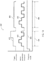
FIG. 9 illustrates a pulse diagram 400 for an operation of thecontroller 200 during a recording mode according to an embodiment of the invention. Thecontroller 200 receives a user mode signal from the usermode selector switch 165 and begins the recording mode at 405. According to the embodiment illustrated inFIG. 9 , the recording mode comprises a timed mode in which data from the desired motor parameter is measured and recorded from the start of the record mode until the end of the record mode, which may be aspecific time period 410 or may be ended by the user changing the user mode to the playback mode or to the normal use mode. In the timed mode, data for the desired motor parameter is measured whether or not there is an activation signal from the trigger mechanism 195. Accordingly, during periods in which there is no trigger activation that causes activation of the motor, the data for the desired recorded motor parameter is measured and recorded even if the measured data results in values that do not cause activation of the motor. - As illustrated in
FIG. 9 , the start ofrecord mode 405 begins recording the usage of the motor parameter prior to receiving an activation signal from the trigger assembly. When the trigger assembly is activated at 412, themotor parameter signal 415 that is changed thereby is measured and recorded during the recording of the usage. The resulting recordedmotor parameter signal 420 is stored and used during playback as described herein below. The recordedmotor parameter signal 420 may be stored in its entirety including the blank or null portions for which no motor control parameter was manipulated or recorded during the record mode or maybe truncated to theportion 425 for which the motor control parameter signals 415 were recorded during the record mode. The truncation may occur after recording for storage and later playback or may be truncated during the playback mode. - According to embodiments of the invention, the motor parameter signals 415 that are measured and recorded during the record mode may include PWM duty cycle (amount of trigger pull), the speed of the motor, the torque of the motor, the power to the motor, the number of impact "blows", and other motor parameters.
-
FIG. 10 illustrates a pulse diagram 430 for an operation of thecontroller 200 during a recording mode according to another embodiment of the invention. Thecontroller 200 receives a user mode signal from the usermode selector switch 165 to begin the recording mode at 405, but does not begin recording the usage of themotor parameter signal 415 until activation of the trigger begins at 412. According to the embodiment illustrated inFIG. 10 , the recording mode comprises a timed mode in which data from themotor parameter signal 415 is measured and recorded from the start of the trigger activation at 412 until the end of therecord mode 405, which may be aspecific time period 410 or may be ended by the user changing the user mode to the playback mode or to the normal use mode. In this mode, data for themotor parameter signal 415 is measured beginning from when the trigger is first activated at 412 and continues whether or not there is an activation signal from the trigger mechanism 195 until the end of the recording mode 405 (e.g., the end of the time period 410). Accordingly, during periods in which there is no trigger activation (e.g., time period 435) that causes activation of the motor once recording has begun, the data for the desired recorded motor parameter is measured and recorded even if the measured data results in values that do not cause activation of the motor. - As illustrated in
FIG. 10 , the start ofrecord mode 405 begins recording the usage of themotor parameter signal 415 at the first activation of the trigger assembly at 412. When the trigger assembly is activated, themotor parameter signal 415 that is changed thereby is measured and recorded during the recording of the usage. Since recording continues after the first trigger activation at 412 even when there is no activation of the trigger (e.g., during period 435), subsequenttrigger activation pulses motor parameter signal 420 is stored and used during playback as described herein below. The recordedmotor parameter signal 420 may be stored in its entirety including the blank or null portions for which no motor control parameter was manipulated or recorded during the record mode or maybe truncated to theportion 425 for which motor control parameter signals 415 were recorded during therecord mode 405. The truncation may occur after recording for storage and later playback or may be truncated during the playback mode. -
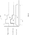
FIG. 11 illustrates a pulse diagram 450 for an operation of thecontroller 200 during a recording mode according to another embodiment of the invention. Thecontroller 200 receives a user mode signal from the usermode selector switch 165 to begin the recording mode at 405, but does not begin recording the usage of themotor parameter signal 415 until activation of the trigger begins at 412. According to the embodiment illustrated inFIG. 11 , the recording mode comprises a trigger-recording mode in which data from themotor parameter signal 415 is measured and recorded from the start of the trigger activation at 412 until the end of the single trigger activation event at 452. In this mode, data for themotor parameter signal 415 is measured beginning from when the trigger is first activated at 412 and terminates when the activation signal from the trigger mechanism 195 is first ended at 452. Accordingly, the data for themotor parameter signal 415 is measured and recorded only during the first, single trigger activation signal. - As illustrated in
FIG. 11 , the start ofrecord mode 405 begins recording the usage of themotor parameter signal 415 at the first activation of the trigger assembly at 412. When the trigger assembly is activated at 412, themotor parameter signal 415 that is changed thereby is measured and recorded during the recording of the usage. Since recording stops after the first trigger activation, subsequent trigger activation pulses are not recorded. The resulting recordedmotor parameter signal 420 is stored and used during playback as described herein below. - According to an embodiment of invention, the playback mode of the tool may be automatically set and entered into at the end of the
recording modes 405 illustrated inFIGS. 9-11 . -
FIG. 12 illustrates a pulse diagram 460 for an operation of thecontroller 200 during a playback mode according to another embodiment of the invention. As an example, the recordedmotor parameter signal 420 ofFIG. 10 is used for the pulse diagram 460 ofFIG. 12 . Thecontroller 200 receives a user mode signal from the usermode selector switch 165 to begin theplayback mode 465 but does not begin executing the recordedmotor parameter signal 420 until activation of the trigger begins at 470. - As illustrated, activation of the trigger at 470 begins execution (or playback) of the recorded
motor parameter signal 420 according to what was recorded and stored during therecording mode 405 of pulse diagram 430. While thetrigger activation pulse 470 does not match the executed recordedmotor parameter signal 420, execution of the recordedmotor parameter signal 420 allows for repeatability of the recorded parameter even when thetrigger activation signal 470 does not match. Accordingly, a different trigger activation signal profile nevertheless causes the recordedmotor parameter signal 420 to be executed. In this manner, the recordedmotor parameter signal 420 may be reliably repeated for tasks such as motor line assembly scenarios or other such tasks where predictability of tool use is desired. As illustrated, when therecording time period 410 is ended, the executed recordedmotor parameter signal 420 is also ended, and even thoughtrigger activation signal 470 illustrates that the trigger mechanism 195 is still being activated, the tool motor is not activated since the recordedmotor parameter signal 420 has ended. The recordedmotor parameter signal 420 is not executed again until reactivation of the trigger mechanism 195 a subsequent time duringplayback mode 465 in one embodiment. - According to another embodiment of the invention, the recorded
motor parameter signal 420 is repeatedly executed as long as the trigger mechanism 195 is activated. In this manner, for example, a recorded parameter signal (e.g., the recorded motor parameter signal 420) that oscillates the motor parameter between two or more values may continue to oscillate the motor parameter for a longer duration of the trigger activation. As such, a short recorded signal may be extended and be executed many times repeatedly during a long trigger activation time. -
FIG. 13 illustrates a pulse diagram 480 for an operation of thecontroller 200 during a playback mode according to another embodiment of the invention. As an example, the recordedmotor parameter signal 420 ofFIG. 10 is used for the pulse diagram 480 ofFIG. 13 . Thecontroller 200 receives a user mode signal from the usermode selector switch 165 to begin theplayback mode 465 but does not begin executing the recordedmotor parameter signal 420 until activation of the trigger begins at 470. - As illustrated, however, at the end of a first
trigger activation time 485 that may be caused, for example, by the user releasing the trigger mechanism 195, playback of the recordedmotor parameter signal 420 is halted when the trigger mechanism 195 is released. When the trigger mechanism 195 is re-activated during a subsequenttrigger activation signal 490, the recordedmotor parameter signal 420 is played back from the beginning during a secondtrigger activation time 495 even though it was halted during the previous execution. In this manner, playback of the recordedmotor parameter signal 420 is re-initiated from the beginning each time the trigger mechanism 195 is re-activated. -
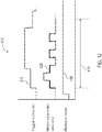
FIG. 14 illustrates a pulse diagram 500 for an operation of thecontroller 200 during a playback mode according to another embodiment of the invention. As an example, the recordedparameter signal 420 ofFIG. 11 is used for the pulse diagram 500 ofFIG. 14 . Thecontroller 200 receives a user mode signal from the usermode selector switch 165 to begin theplayback mode 465 but does not begin executing the recordedmotor parameter signal 420 until activation of the trigger begins at 510. A direction signal from thedirection switch 220 illustrates that the tool is in aforward mode direction 505 at the beginning of theplayback mode 465. - Similar to that illustrated in
FIG. 12 , at the end of a firsttrigger activation time 515 that may be caused, for example, by the user releasing the trigger mechanism 195, playback of the recordedmotor parameter signal 420 is halted when the trigger mechanism 195 is released. For example, the user may stop thetrigger activation 510 in order to switch thedirection switch 220 to thereverse direction mode 520 in order to engage a fastener to back it out of its current position prior to re-engaging the fastener to drive it forward. During thereverse mode 520, the recordedmotor parameter signal 420 is not executed, but instead, thetrigger activation signal 525 at atime 530 controls the motor according to a normal operating mode such that themotor parameter signal 535 executed during thereverse mode 520 directly corresponds with thetrigger activation signal 525. Whileplayback mode 465 is illustrated as continuing to be active throughout the direction change into thereverse mode 520,playback mode 465 may be deactivated as illustrated in phantom at 537 while thereverse mode 520 is engaged. When theforward mode 505 is re-engaged viadirection switch 220 and the trigger mechanism 195 is re-activated during a subsequenttrigger activation signal 540, the recordedmotor parameter signal 420 is played back from the beginning during a secondtrigger activation time 545 even though it was halted during the previous execution. In this manner, playback of the recordedmotor parameter signal 420 is re-initiated from the beginning each time the trigger mechanism 195 is re-activated. - Referring to
FIG. 15 , in the illustrated embodiment, the usermode selector switch 165 is located within thepocket 170 proximate to themotor 180 and accessible from thetop surface 120 of thetool housing 105. The compact design of the usermode selector switch 165 allows it to be placed in the relatively small space above themotor 180. Further, the lightweight design of the usermode selector switch 165 adds little weight to thetool 100. - As shown in
FIG. 16 , with themotor 180 removed for viewing purposes, wires 550 for the usermode selector switch 165 run along a side of theinterior surface 160 of thebody portion 110 and electrically couple the usermode selector switch 165 to thePCB 175. - The cordless, hand-held power tool illustrated in
FIGS. 17-18 is animpact wrench 600. Theimpact wrench 600 includes an uppermain body 604, ahandle portion 608, a batterypack receiving portion 612, user mode selector switch(es) 165, mode indicators 301-303, an output drive device ormechanism 616, a forward/reverse selection button 220, atrigger 215, and air vents 628. Theimpact wrench 600 also includes aworklight 632. The batterypack receiving portion 612 receives a portion of a battery pack and includes a terminal assembly including a plurality of terminals. The number of terminals present in the receivingportion 612 can vary based on the type of hand-held power tool. However, as an illustrative example, the receivingportion 612 and the terminal assembly can include a battery positive ("B+") terminal, a battery negative ("B-") terminal, a sense or communication terminal, an identification terminal, etc. The outer portions or housing of the impact wrench 600 (e.g., themain body 604 and the handle portion 608) are composed of a durable and light-weight plastic material. Thedrive mechanism 616 is composed of a metal (e.g., steel) as is known in the art. - The battery positive and battery negative terminals are operable to electrically connect the battery pack to the hand-held power tool and provide operational power (i.e., voltage and current) for the hand-held power tool from the battery pack to the hand-held power tool. The sensor or communication terminal is operable to provide for communication or sensing for the hand-held power tool of the battery pack. For example, the communication can include serial communication or a serial communication link, the transmission or conveyance of information from one of the battery pack or the hand-held power tool to the other of the battery pack or hand-held power tool related to a condition or characteristic of the battery pack or hand-held power tool (e.g., one or more battery cell voltages, one or more battery pack voltages, one or more battery cell temperatures, one or more battery pack temperatures, etc.).
- The identification terminal can be used by the battery pack or the hand-held power tool to identify the other of the battery pack or the hand-held power tool. For example, the hand-held power tool can identify the battery pack as a high capacity battery pack or a normal capacity battery pack, as a lithium-based battery or a nickel-based battery, as a battery pack having a particular voltage (described below), a higher resistance battery pack, a lower resistance battery pack, etc. Additionally or alternatively, the battery pack can identify the hand-held power tool as a hammer drill, a drill/wrench, an impact wrench, an impact wrench, a brushless power tool, a brushed power tool, a higher resistance power tool (e.g., capable of lower power output), a lower resistance power tool (e.g., capable of higher power output), etc.
- One of skill in the art will recognize that embodiments of the invention may be incorporated into tools such as power drills, impact drivers, power saws, angle drivers, and other tools incorporating a user-activated trigger mechanism. One skilled in the art will also recognize that the trigger activation signals, while illustrated as being discrete steps, are merely examples and that other continuous types of trigger activation signals are contemplated herein.
- Thus, the invention provides, among other things, a power tool including a speed selector switch for selecting an operating speed of the power tool. Various features and advantages of the invention are set forth in the following claims.
Claims (17)
- A power tool (100) comprising:a tool housing (105) defining a cavity (162);a motor (180) positioned within the cavity;a trigger (195) coupled to the tool housing, the trigger configured to output an activation signal based on a user input;a mode selector switch (165) configured to receive a user mode selection, the user mode selection indicating an operating mode selected from the group of a recording mode, a normal operating mode, and a playback mode; anda controller (200) coupled to the trigger, the mode selector switch, and the motor, the controller configured to
receive a mode selection signal from the mode selector switch, the mode selection signal indicative of the user mode selection for the power tool,
enter the recording mode when the user mode selection indicates the recording mode,
record a motor parameter while the power tool is in the recording mode and the motor is operating to generate a recorded motor parameter,
enter the playback mode when the user mode selection indicates the playback mode, and
operate the motor based on the recorded motor parameter upon receiving the activation signal from the trigger while the power tool is in the playback mode. - The power tool (100) of claim 1, wherein the controller is configured to
enter the normal operating mode when the user mode selection indicates the normal operating mode, and
control a current supplied to the motor (180) corresponding to the activation signal from the trigger (195) while the power tool is in the normal operating mode. - The power tool (100) of claim 1, wherein;
the motor parameter includes one of a duty cycle indicating trigger pull, a motor speed, a motor torque, a motor power, and a number of impact activations; and/or
the controller (200) is configured to begin to record the motor parameter for a predetermined time period upon entering the recording mode. - The power tool (100) of claim 1, wherein, after entering the recording mode, the controller (200) is configured to begin to record the motor parameter of the power tool upon receiving the activation signal from the trigger (195).
- The power tool (100) of claim 4, wherein the controller (200) is configured to stop recording the motor parameter upon detecting a release of the trigger (195).
- The power tool (100) of claim 1, wherein, while in the recording mode, the controller (200) is configured to record the motor parameter until the operating mode changes.
- The power tool (100) of claim 1, wherein the trigger (195) moves between a depressed state, in which the trigger outputs the activation signal, and a released state, in which the trigger does not output the activation signal, and wherein, while in the playback mode, the controller (200) is configured to operate the motor (180) based on the recorded motor parameter when the trigger is in the depressed state.
- The power tool (100) of claim 7, wherein;
the recorded the motor parameter has a duration, and wherein, while the power tool is in the playback mode and the trigger (195) is in the depressed state, the controller (200) is configured to stop operating the motor (180) based on the recorded motor parameter when the duration ends; and/or
while the power tool is in the playback mode, the controller is configured to repeat playback of the recorded motor parameter, by repeating operation of the motor based on the recorded motor parameter, until the trigger changes from the depressed state to the released state. - The power tool (100) of claim 1, further comprising a direction switch (220) switchable between a first direction and a second direction, the direction switch configured to indicate a desired motor direction, and wherein the controller (200) is further configured to switch from the playback mode to the normal operating mode when the direction switch is switched.
- The power tool (100) of claim 1, further comprising a mode indicator (295) for indicating the operating mode to a user.
- The power tool (100) of claim 1, wherein to generate the recorded motor parameter, the controller (200) is further configured to:record the motor parameter during periods of trigger activation;record the motor parameter during periods of no trigger activation; andtruncate the recorded motor parameter to the portion for which motor control parameter signals were recorded.
- A method of operating a power tool (100) including a motor (180), a mode selector switch (165), a trigger (195), and a controller (200), the method comprising:receiving, by the mode selector switch, a user mode selection indicating an operating mode for the power tool, the operating mode selected from the group of a recording mode, a playback mode, and a normal operating mode;entering, by the controller, the recording mode when the user mode selection indicates the recording mode;recording, by the controller, a motor parameter while the power tool is in the recording mode and the motor is operating to generate a recorded motor parameter;entering, by the controller, the playback mode when the user mode selection indicates the playback mode; andreceiving, by the controller, an activation signal from the trigger;executing, by the controller, the recorded motor parameter to operate the motor based on the recorded motor parameter upon receipt of the activation signal while the power tool is in the playback mode.
- The method of claim 11, further comprising
entering, by the controller (200), the normal operating mode when the user mode selection indicates the normal operating mode; and
controlling a current, by the controller, supplied to the motor (180) corresponding to the activation signal from the trigger (195) while the power tool (100) is in the normal operating mode. - The method of claim 11, wherein;
generating the recorded motor parameter includes recording the motor parameter for a predetermined amount of time after receiving the activation signal from the trigger (195) while in the recording mode; and/or
generating the recorded motor parameter includes recording the motor parameter for a predetermined amount of time upon entering the recording mode. - The method of claim 11, further comprising;
stopping the recording of the motor parameter after detecting that the trigger (195) is in a released state; and/or
switching, by the controller (200), between the playback mode and the normal operating mode based on a switching of a motor direction switch (220); and/or
entering the playback mode automatically when the recording of the motor parameter ends. - The method of claim 11, wherein the recorded motor parameter covers
a first time period in which the motor (180) is operating in response to depression of the trigger (195),
a second time period in which the motor is inactive in response to release of the trigger, and
a third time period in which the motor is operating in response to another depression of the trigger. - The method of claim 11, wherein generating the recorded motor parameter further comprises:recording the motor parameter during periods of trigger activation;recording the motor parameter during periods of no trigger activation; andtruncating the recorded motor parameter to the portion for which motor control parameter signals were recorded.
Applications Claiming Priority (2)
| Application Number | Priority Date | Filing Date | Title |
|---|---|---|---|
| US201361788510P | 2013-03-15 | 2013-03-15 | |
| PCT/US2014/028721 WO2014144353A1 (en) | 2013-03-15 | 2014-03-14 | Power tool operation recording and playback |
Publications (3)
| Publication Number | Publication Date |
|---|---|
| EP2969397A1 EP2969397A1 (en) | 2016-01-20 |
| EP2969397A4 EP2969397A4 (en) | 2016-11-09 |
| EP2969397B1 true EP2969397B1 (en) | 2019-07-31 |
Family
ID=51522374
Family Applications (1)
| Application Number | Title | Priority Date | Filing Date |
|---|---|---|---|
| EP14764096.5A Active EP2969397B1 (en) | 2013-03-15 | 2014-03-14 | Power tool operation recording and playback |
Country Status (4)
| Country | Link |
|---|---|
| US (4) | US9744658B2 (en) |
| EP (1) | EP2969397B1 (en) |
| CN (1) | CN105142862B (en) |
| WO (1) | WO2014144353A1 (en) |
Families Citing this family (22)
| Publication number | Priority date | Publication date | Assignee | Title |
|---|---|---|---|---|
| US9272799B2 (en) | 2011-10-04 | 2016-03-01 | Signode Industrial Group Llc | Sealing tool for strap |
| CN105142862B (en) * | 2013-03-15 | 2018-05-15 | 米沃奇电动工具公司 | Operating electric tool is recorded and reproduced |
| KR101641928B1 (en) * | 2015-04-08 | 2016-07-25 | 사이언스메딕 주식회사 | The surgical handpiece with direction exchanging function |
| US10998805B2 (en) * | 2015-07-23 | 2021-05-04 | Black & Decker Inc. | Power tool with direction sensing controller |
| US10345797B2 (en) | 2015-09-18 | 2019-07-09 | Milwaukee Electric Tool Corporation | Power tool operation recording and playback |
| US10577137B2 (en) | 2015-12-09 | 2020-03-03 | Signode Industrial Group Llc | Electrically powered combination hand-held notch-type strapping tool |
| DE102015226374A1 (en) * | 2015-12-21 | 2017-06-22 | Robert Bosch Gmbh | Method for operating a power tool |
| DE102016222178A1 (en) * | 2016-11-11 | 2018-05-17 | Robert Bosch Gmbh | Hand tool with a Moduseinstelleinrichtung |
| US10512964B2 (en) * | 2016-12-14 | 2019-12-24 | Ridge Tool Company | Electrically powered crimp tool |
| CN106811947B (en) * | 2017-02-24 | 2023-04-14 | 福州肆菱智能科技有限公司 | Industrial ironing machine |
| EP3706960A4 (en) * | 2017-11-07 | 2021-07-28 | Milwaukee Electric Tool Corporation | Non-contact speed selector swtich in rotary power tool |
| US20190217459A1 (en) * | 2018-01-16 | 2019-07-18 | Tti (Macao Commercial Offshore) Limited | Operational data distribution in a power tool |
| US11207756B2 (en) | 2018-04-12 | 2021-12-28 | Milwaukee Electric Tool Corporation | Power tool blade type detection and automatic speed adjustment |
| WO2020048529A1 (en) * | 2018-09-06 | 2020-03-12 | 苏州宝时得电动工具有限公司 | Handheld power tool, and control method and operation method therefor |
| TWI733067B (en) * | 2018-12-06 | 2021-07-11 | 優鋼機械股份有限公司 | Setting method of electronic torque tool |
| CN111347377A (en) * | 2018-12-24 | 2020-06-30 | 苏州宝时得电动工具有限公司 | Control device of electric tool and electric tool with same |
| DE102019215415A1 (en) * | 2019-10-09 | 2021-04-15 | Robert Bosch Gmbh | Method for teaching in application shutdowns with the help of finding characteristic signal forms when operating a handheld power tool |
| DE102019215417A1 (en) | 2019-10-09 | 2021-04-15 | Robert Bosch Gmbh | Method for operating a hand machine tool |
| AU2021104983A4 (en) | 2020-09-10 | 2021-09-30 | Techtronic Cordless Gp | Blade replacement mechanism of electric instrument |
| CN112518648B (en) * | 2020-11-25 | 2024-01-30 | 浙江科佳机械有限公司 | Universal fastener installation device |
| DE102020215988A1 (en) | 2020-12-16 | 2022-06-23 | Robert Bosch Gesellschaft mit beschränkter Haftung | Method for operating a handheld power tool |
| EP4272901A1 (en) * | 2022-05-03 | 2023-11-08 | Milwaukee Electric Tool Corporation | Method and power tool including loss of control mitigation |
Family Cites Families (38)
| Publication number | Priority date | Publication date | Assignee | Title |
|---|---|---|---|---|
| AT226034B (en) * | 1958-10-31 | 1963-02-25 | Stephan Ing Findeis | Electrically controlled machine tool |
| US7613590B2 (en) | 1992-11-17 | 2009-11-03 | Health Hero Network, Inc. | Modular microprocessor-based power tool system |
| GB9320181D0 (en) | 1993-09-30 | 1993-11-17 | Black & Decker Inc | Improvements in and relating to power tools |
| US6536536B1 (en) | 1999-04-29 | 2003-03-25 | Stephen F. Gass | Power tools |
| JP2001357574A (en) * | 2000-06-15 | 2001-12-26 | Sharp Corp | Magneto-optical recording and reproducing device |
| EP1867438A3 (en) | 2000-11-17 | 2009-01-14 | Makita Corporation | Impact power tools |
| US6495983B1 (en) | 2001-06-28 | 2002-12-17 | Michael A. Stern | Integrated closed-loop programmable motor assembly |
| US7239944B2 (en) | 2002-03-28 | 2007-07-03 | Dean Jason A | Programmable lawn mower |
| JP4250907B2 (en) * | 2002-04-23 | 2009-04-08 | パナソニック電工株式会社 | Electric tool |
| JP2005066785A (en) * | 2003-08-26 | 2005-03-17 | Matsushita Electric Works Ltd | Power tool |
| US6868571B1 (en) * | 2003-10-08 | 2005-03-22 | Credo Technology Corporation | Memo recorder/tape measuring module |
| US20060234617A1 (en) * | 2005-03-25 | 2006-10-19 | Black & Decker Inc. | Power tool accessory identification system |
| US7557534B2 (en) * | 2005-05-17 | 2009-07-07 | Milwaukee Electric Tool Corporation | Power tool, battery, charger and method of operating the same |
| JP4400519B2 (en) * | 2005-06-30 | 2010-01-20 | パナソニック電工株式会社 | Impact rotary tool |
| JP4961808B2 (en) * | 2006-04-05 | 2012-06-27 | マックス株式会社 | Rebar binding machine |
| JP4669455B2 (en) | 2006-08-31 | 2011-04-13 | パナソニック電工株式会社 | Electric tool |
| JP5242974B2 (en) | 2007-08-24 | 2013-07-24 | 株式会社マキタ | Electric tool |
| JP5126515B2 (en) * | 2008-05-08 | 2013-01-23 | 日立工機株式会社 | Oil pulse tool |
| US20100268521A1 (en) | 2009-04-17 | 2010-10-21 | Rainer Heller | Monitoring An Automation System |
| AU2011204260A1 (en) | 2010-01-07 | 2012-06-07 | Black & Decker Inc. | Power screwdriver having rotary input control |
| JP2011156629A (en) | 2010-02-02 | 2011-08-18 | Makita Corp | Motor control device, electric power tool, and program |
| CN102844155A (en) * | 2010-02-25 | 2012-12-26 | 迪美科技控股有限公司 | Power tool and accessory storage system |
| US20130051080A1 (en) * | 2010-02-25 | 2013-02-28 | Demain Technology Pty Ltd | Power station assembly |
| US8674640B2 (en) | 2011-01-05 | 2014-03-18 | Makita Corporation | Electric power tool |
| US20140069672A1 (en) * | 2011-05-20 | 2014-03-13 | Hitachi Koki Co., Ltd. | Power Tool |
| DE102011104901B4 (en) | 2011-06-16 | 2018-04-12 | C. & E. Fein Gmbh | Powered hand tool machine |
| US9239574B2 (en) | 2011-06-30 | 2016-01-19 | Honeywell International Inc. | Apparatus for automating field device operations by capturing device method execution steps for later use and related method |
| WO2013014914A2 (en) * | 2011-07-24 | 2013-01-31 | Makita Corporation | Adapter for power tools, power tool system and method of operating the same |
| WO2013063507A1 (en) * | 2011-10-26 | 2013-05-02 | Milwaukee Electric Tool Corporation | Wireless tracking of power tools and related devices |
| CA2800792C (en) | 2012-01-06 | 2016-10-25 | Sears Brands, Llc | Programmable portable power tool with brushless dc motor |
| US9908182B2 (en) * | 2012-01-30 | 2018-03-06 | Black & Decker Inc. | Remote programming of a power tool |
| US20140284070A1 (en) * | 2012-06-08 | 2014-09-25 | Black & Decker Inc. | Operating mode indicator for a power tool |
| EP2895301A2 (en) * | 2012-09-11 | 2015-07-22 | Black & Decker, Inc. | System and method for identifying a power tool |
| US9367062B2 (en) * | 2012-12-31 | 2016-06-14 | Robert Bosch Gmbh | System and method for operational data retrieval from a power tool |
| CN105142862B (en) * | 2013-03-15 | 2018-05-15 | 米沃奇电动工具公司 | Operating electric tool is recorded and reproduced |
| DE102013212003A1 (en) * | 2013-06-25 | 2015-01-08 | Robert Bosch Gmbh | Hand tool |
| US10011006B2 (en) * | 2013-08-08 | 2018-07-03 | Black & Decker Inc. | Fastener setting algorithm for drill driver |
| US10345797B2 (en) * | 2015-09-18 | 2019-07-09 | Milwaukee Electric Tool Corporation | Power tool operation recording and playback |
-
2014
- 2014-03-14 CN CN201480014135.1A patent/CN105142862B/en active Active
- 2014-03-14 EP EP14764096.5A patent/EP2969397B1/en active Active
- 2014-03-14 WO PCT/US2014/028721 patent/WO2014144353A1/en active Application Filing
- 2014-03-14 US US14/213,098 patent/US9744658B2/en active Active
-
2017
- 2017-07-21 US US15/656,950 patent/US11207770B2/en active Active
-
2021
- 2021-12-28 US US17/563,466 patent/US11738437B2/en active Active
-
2023
- 2023-08-18 US US18/452,324 patent/US20230390912A1/en active Pending
Non-Patent Citations (1)
| Title |
|---|
| None * |
Also Published As
| Publication number | Publication date |
|---|---|
| US11738437B2 (en) | 2023-08-29 |
| US11207770B2 (en) | 2021-12-28 |
| US20220193876A1 (en) | 2022-06-23 |
| US9744658B2 (en) | 2017-08-29 |
| EP2969397A4 (en) | 2016-11-09 |
| US20170320207A1 (en) | 2017-11-09 |
| WO2014144353A1 (en) | 2014-09-18 |
| EP2969397A1 (en) | 2016-01-20 |
| CN105142862B (en) | 2018-05-15 |
| CN105142862A (en) | 2015-12-09 |
| US20140262389A1 (en) | 2014-09-18 |
| US20230390912A1 (en) | 2023-12-07 |
Similar Documents
| Publication | Publication Date | Title |
|---|---|---|
| US11738437B2 (en) | Power tool operation recording and playback | |
| US9457462B2 (en) | Power tool having a speed selector switch | |
| US11909548B2 (en) | Power tool operation recording and playback | |
| US10967489B2 (en) | Power tool communication system | |
| US11407091B2 (en) | Power tool | |
| EP2030710B1 (en) | Power tool and control system for a power tool | |
| CN106998168B (en) | Electric working machine | |
| JP5697457B2 (en) | Electric tool | |
| JP2015091626A (en) | Electric power tool | |
| JP7108928B2 (en) | Electric tool | |
| WO2021220992A1 (en) | Work machine |
Legal Events
| Date | Code | Title | Description |
|---|---|---|---|
| PUAI | Public reference made under article 153(3) epc to a published international application that has entered the european phase |
Free format text: ORIGINAL CODE: 0009012 |
|
| 17P | Request for examination filed |
Effective date: 20150914 |
|
| AK | Designated contracting states |
Kind code of ref document: A1 Designated state(s): AL AT BE BG CH CY CZ DE DK EE ES FI FR GB GR HR HU IE IS IT LI LT LU LV MC MK MT NL NO PL PT RO RS SE SI SK SM TR |
|
| AX | Request for extension of the european patent |
Extension state: BA ME |
|
| RIN1 | Information on inventor provided before grant (corrected) |
Inventor name: SIMEONE, THOMAS, G. Inventor name: MERGENER, MATTHEW, J. Inventor name: WYCKLENDT, MATTHEW |
|
| DAX | Request for extension of the european patent (deleted) | ||
| A4 | Supplementary search report drawn up and despatched |
Effective date: 20161011 |
|
| RIC1 | Information provided on ipc code assigned before grant |
Ipc: B25B 23/151 20060101AFI20161005BHEP Ipc: B23B 45/02 20060101ALI20161005BHEP Ipc: B25F 5/00 20060101ALI20161005BHEP Ipc: B25B 21/00 20060101ALI20161005BHEP |
|
| GRAP | Despatch of communication of intention to grant a patent |
Free format text: ORIGINAL CODE: EPIDOSNIGR1 |
|
| STAA | Information on the status of an ep patent application or granted ep patent |
Free format text: STATUS: GRANT OF PATENT IS INTENDED |
|
| INTG | Intention to grant announced |
Effective date: 20190225 |
|
| GRAS | Grant fee paid |
Free format text: ORIGINAL CODE: EPIDOSNIGR3 |
|
| GRAA | (expected) grant |
Free format text: ORIGINAL CODE: 0009210 |
|
| STAA | Information on the status of an ep patent application or granted ep patent |
Free format text: STATUS: THE PATENT HAS BEEN GRANTED |
|
| AK | Designated contracting states |
Kind code of ref document: B1 Designated state(s): AL AT BE BG CH CY CZ DE DK EE ES FI FR GB GR HR HU IE IS IT LI LT LU LV MC MK MT NL NO PL PT RO RS SE SI SK SM TR |
|
| REG | Reference to a national code |
Ref country code: CH Ref legal event code: EP Ref country code: GB Ref legal event code: FG4D |
|
| REG | Reference to a national code |
Ref country code: DE Ref legal event code: R096 Ref document number: 602014050897 Country of ref document: DE |
|
| REG | Reference to a national code |
Ref country code: AT Ref legal event code: REF Ref document number: 1160417 Country of ref document: AT Kind code of ref document: T Effective date: 20190815 |
|
| REG | Reference to a national code |
Ref country code: IE Ref legal event code: FG4D |
|
| REG | Reference to a national code |
Ref country code: NL Ref legal event code: MP Effective date: 20190731 |
|
| REG | Reference to a national code |
Ref country code: LT Ref legal event code: MG4D |
|
| REG | Reference to a national code |
Ref country code: AT Ref legal event code: MK05 Ref document number: 1160417 Country of ref document: AT Kind code of ref document: T Effective date: 20190731 |
|
| PG25 | Lapsed in a contracting state [announced via postgrant information from national office to epo] |
Ref country code: FI Free format text: LAPSE BECAUSE OF FAILURE TO SUBMIT A TRANSLATION OF THE DESCRIPTION OR TO PAY THE FEE WITHIN THE PRESCRIBED TIME-LIMIT Effective date: 20190731 Ref country code: NL Free format text: LAPSE BECAUSE OF FAILURE TO SUBMIT A TRANSLATION OF THE DESCRIPTION OR TO PAY THE FEE WITHIN THE PRESCRIBED TIME-LIMIT Effective date: 20190731 Ref country code: SE Free format text: LAPSE BECAUSE OF FAILURE TO SUBMIT A TRANSLATION OF THE DESCRIPTION OR TO PAY THE FEE WITHIN THE PRESCRIBED TIME-LIMIT Effective date: 20190731 Ref country code: BG Free format text: LAPSE BECAUSE OF FAILURE TO SUBMIT A TRANSLATION OF THE DESCRIPTION OR TO PAY THE FEE WITHIN THE PRESCRIBED TIME-LIMIT Effective date: 20191031 Ref country code: HR Free format text: LAPSE BECAUSE OF FAILURE TO SUBMIT A TRANSLATION OF THE DESCRIPTION OR TO PAY THE FEE WITHIN THE PRESCRIBED TIME-LIMIT Effective date: 20190731 Ref country code: AT Free format text: LAPSE BECAUSE OF FAILURE TO SUBMIT A TRANSLATION OF THE DESCRIPTION OR TO PAY THE FEE WITHIN THE PRESCRIBED TIME-LIMIT Effective date: 20190731 Ref country code: NO Free format text: LAPSE BECAUSE OF FAILURE TO SUBMIT A TRANSLATION OF THE DESCRIPTION OR TO PAY THE FEE WITHIN THE PRESCRIBED TIME-LIMIT Effective date: 20191031 Ref country code: LT Free format text: LAPSE BECAUSE OF FAILURE TO SUBMIT A TRANSLATION OF THE DESCRIPTION OR TO PAY THE FEE WITHIN THE PRESCRIBED TIME-LIMIT Effective date: 20190731 Ref country code: PT Free format text: LAPSE BECAUSE OF FAILURE TO SUBMIT A TRANSLATION OF THE DESCRIPTION OR TO PAY THE FEE WITHIN THE PRESCRIBED TIME-LIMIT Effective date: 20191202 |
|
| PG25 | Lapsed in a contracting state [announced via postgrant information from national office to epo] |
Ref country code: IS Free format text: LAPSE BECAUSE OF FAILURE TO SUBMIT A TRANSLATION OF THE DESCRIPTION OR TO PAY THE FEE WITHIN THE PRESCRIBED TIME-LIMIT Effective date: 20191130 Ref country code: LV Free format text: LAPSE BECAUSE OF FAILURE TO SUBMIT A TRANSLATION OF THE DESCRIPTION OR TO PAY THE FEE WITHIN THE PRESCRIBED TIME-LIMIT Effective date: 20190731 Ref country code: ES Free format text: LAPSE BECAUSE OF FAILURE TO SUBMIT A TRANSLATION OF THE DESCRIPTION OR TO PAY THE FEE WITHIN THE PRESCRIBED TIME-LIMIT Effective date: 20190731 Ref country code: AL Free format text: LAPSE BECAUSE OF FAILURE TO SUBMIT A TRANSLATION OF THE DESCRIPTION OR TO PAY THE FEE WITHIN THE PRESCRIBED TIME-LIMIT Effective date: 20190731 Ref country code: RS Free format text: LAPSE BECAUSE OF FAILURE TO SUBMIT A TRANSLATION OF THE DESCRIPTION OR TO PAY THE FEE WITHIN THE PRESCRIBED TIME-LIMIT Effective date: 20190731 |
|
| PG25 | Lapsed in a contracting state [announced via postgrant information from national office to epo] |
Ref country code: TR Free format text: LAPSE BECAUSE OF FAILURE TO SUBMIT A TRANSLATION OF THE DESCRIPTION OR TO PAY THE FEE WITHIN THE PRESCRIBED TIME-LIMIT Effective date: 20190731 |
|
| PG25 | Lapsed in a contracting state [announced via postgrant information from national office to epo] |
Ref country code: IT Free format text: LAPSE BECAUSE OF FAILURE TO SUBMIT A TRANSLATION OF THE DESCRIPTION OR TO PAY THE FEE WITHIN THE PRESCRIBED TIME-LIMIT Effective date: 20190731 Ref country code: EE Free format text: LAPSE BECAUSE OF FAILURE TO SUBMIT A TRANSLATION OF THE DESCRIPTION OR TO PAY THE FEE WITHIN THE PRESCRIBED TIME-LIMIT Effective date: 20190731 Ref country code: PL Free format text: LAPSE BECAUSE OF FAILURE TO SUBMIT A TRANSLATION OF THE DESCRIPTION OR TO PAY THE FEE WITHIN THE PRESCRIBED TIME-LIMIT Effective date: 20190731 Ref country code: RO Free format text: LAPSE BECAUSE OF FAILURE TO SUBMIT A TRANSLATION OF THE DESCRIPTION OR TO PAY THE FEE WITHIN THE PRESCRIBED TIME-LIMIT Effective date: 20190731 Ref country code: DK Free format text: LAPSE BECAUSE OF FAILURE TO SUBMIT A TRANSLATION OF THE DESCRIPTION OR TO PAY THE FEE WITHIN THE PRESCRIBED TIME-LIMIT Effective date: 20190731 |
|
| PG25 | Lapsed in a contracting state [announced via postgrant information from national office to epo] |
Ref country code: SK Free format text: LAPSE BECAUSE OF FAILURE TO SUBMIT A TRANSLATION OF THE DESCRIPTION OR TO PAY THE FEE WITHIN THE PRESCRIBED TIME-LIMIT Effective date: 20190731 Ref country code: CZ Free format text: LAPSE BECAUSE OF FAILURE TO SUBMIT A TRANSLATION OF THE DESCRIPTION OR TO PAY THE FEE WITHIN THE PRESCRIBED TIME-LIMIT Effective date: 20190731 Ref country code: SM Free format text: LAPSE BECAUSE OF FAILURE TO SUBMIT A TRANSLATION OF THE DESCRIPTION OR TO PAY THE FEE WITHIN THE PRESCRIBED TIME-LIMIT Effective date: 20190731 Ref country code: IS Free format text: LAPSE BECAUSE OF FAILURE TO SUBMIT A TRANSLATION OF THE DESCRIPTION OR TO PAY THE FEE WITHIN THE PRESCRIBED TIME-LIMIT Effective date: 20200224 |
|
| REG | Reference to a national code |
Ref country code: DE Ref legal event code: R097 Ref document number: 602014050897 Country of ref document: DE |
|
| PLBE | No opposition filed within time limit |
Free format text: ORIGINAL CODE: 0009261 |
|
| STAA | Information on the status of an ep patent application or granted ep patent |
Free format text: STATUS: NO OPPOSITION FILED WITHIN TIME LIMIT |
|
| PG2D | Information on lapse in contracting state deleted |
Ref country code: IS |
|
| PG25 | Lapsed in a contracting state [announced via postgrant information from national office to epo] |
Ref country code: IS Free format text: LAPSE BECAUSE OF FAILURE TO SUBMIT A TRANSLATION OF THE DESCRIPTION OR TO PAY THE FEE WITHIN THE PRESCRIBED TIME-LIMIT Effective date: 20191030 |
|
| 26N | No opposition filed |
Effective date: 20200603 |
|
| PG25 | Lapsed in a contracting state [announced via postgrant information from national office to epo] |
Ref country code: SI Free format text: LAPSE BECAUSE OF FAILURE TO SUBMIT A TRANSLATION OF THE DESCRIPTION OR TO PAY THE FEE WITHIN THE PRESCRIBED TIME-LIMIT Effective date: 20190731 |
|
| PG25 | Lapsed in a contracting state [announced via postgrant information from national office to epo] |
Ref country code: MC Free format text: LAPSE BECAUSE OF FAILURE TO SUBMIT A TRANSLATION OF THE DESCRIPTION OR TO PAY THE FEE WITHIN THE PRESCRIBED TIME-LIMIT Effective date: 20190731 |
|
| REG | Reference to a national code |
Ref country code: CH Ref legal event code: PL |
|
| REG | Reference to a national code |
Ref country code: BE Ref legal event code: MM Effective date: 20200331 |
|
| PG25 | Lapsed in a contracting state [announced via postgrant information from national office to epo] |
Ref country code: LU Free format text: LAPSE BECAUSE OF NON-PAYMENT OF DUE FEES Effective date: 20200314 |
|
| PG25 | Lapsed in a contracting state [announced via postgrant information from national office to epo] |
Ref country code: IE Free format text: LAPSE BECAUSE OF NON-PAYMENT OF DUE FEES Effective date: 20200314 Ref country code: LI Free format text: LAPSE BECAUSE OF NON-PAYMENT OF DUE FEES Effective date: 20200331 Ref country code: FR Free format text: LAPSE BECAUSE OF NON-PAYMENT OF DUE FEES Effective date: 20200331 Ref country code: CH Free format text: LAPSE BECAUSE OF NON-PAYMENT OF DUE FEES Effective date: 20200331 |
|
| PG25 | Lapsed in a contracting state [announced via postgrant information from national office to epo] |
Ref country code: BE Free format text: LAPSE BECAUSE OF NON-PAYMENT OF DUE FEES Effective date: 20200331 |
|
| PG25 | Lapsed in a contracting state [announced via postgrant information from national office to epo] |
Ref country code: MT Free format text: LAPSE BECAUSE OF FAILURE TO SUBMIT A TRANSLATION OF THE DESCRIPTION OR TO PAY THE FEE WITHIN THE PRESCRIBED TIME-LIMIT Effective date: 20190731 Ref country code: CY Free format text: LAPSE BECAUSE OF FAILURE TO SUBMIT A TRANSLATION OF THE DESCRIPTION OR TO PAY THE FEE WITHIN THE PRESCRIBED TIME-LIMIT Effective date: 20190731 |
|
| PG25 | Lapsed in a contracting state [announced via postgrant information from national office to epo] |
Ref country code: MK Free format text: LAPSE BECAUSE OF FAILURE TO SUBMIT A TRANSLATION OF THE DESCRIPTION OR TO PAY THE FEE WITHIN THE PRESCRIBED TIME-LIMIT Effective date: 20190731 |
|
| PG25 | Lapsed in a contracting state [announced via postgrant information from national office to epo] |
Ref country code: GR Free format text: LAPSE BECAUSE OF FAILURE TO SUBMIT A TRANSLATION OF THE DESCRIPTION OR TO PAY THE FEE WITHIN THE PRESCRIBED TIME-LIMIT Effective date: 20190731 |
|
| PGFP | Annual fee paid to national office [announced via postgrant information from national office to epo] |
Ref country code: DE Payment date: 20240327 Year of fee payment: 11 Ref country code: GB Payment date: 20240327 Year of fee payment: 11 |