EP2965858A1 - Real-time tool breakage detection during the friction stir welding process - Google Patents
Real-time tool breakage detection during the friction stir welding process Download PDFInfo
- Publication number
- EP2965858A1 EP2965858A1 EP14468004.8A EP14468004A EP2965858A1 EP 2965858 A1 EP2965858 A1 EP 2965858A1 EP 14468004 A EP14468004 A EP 14468004A EP 2965858 A1 EP2965858 A1 EP 2965858A1
- Authority
- EP
- European Patent Office
- Prior art keywords
- tool
- tool breakage
- welding
- real
- fsw
- Prior art date
- Legal status (The legal status is an assumption and is not a legal conclusion. Google has not performed a legal analysis and makes no representation as to the accuracy of the status listed.)
- Withdrawn
Links
Images


Classifications
-
- B—PERFORMING OPERATIONS; TRANSPORTING
- B23—MACHINE TOOLS; METAL-WORKING NOT OTHERWISE PROVIDED FOR
- B23K—SOLDERING OR UNSOLDERING; WELDING; CLADDING OR PLATING BY SOLDERING OR WELDING; CUTTING BY APPLYING HEAT LOCALLY, e.g. FLAME CUTTING; WORKING BY LASER BEAM
- B23K20/00—Non-electric welding by applying impact or other pressure, with or without the application of heat, e.g. cladding or plating
- B23K20/12—Non-electric welding by applying impact or other pressure, with or without the application of heat, e.g. cladding or plating the heat being generated by friction; Friction welding
- B23K20/122—Non-electric welding by applying impact or other pressure, with or without the application of heat, e.g. cladding or plating the heat being generated by friction; Friction welding using a non-consumable tool, e.g. friction stir welding
- B23K20/123—Controlling or monitoring the welding process
Definitions
- the field of invention is friction stir welding technology (FSW).
- FSW friction stir welding technology
- This disclosure generally relates to an automated process and equipment for FSW and deals more particularly with a system for the detection of tool breakage events and reaction thereto.
- Friction stir welding (FSW) process belongs to the category of solid-phase joining methods. This means that only downward pressure and rotating action of the welding tool is used for the welding process.
- the welding tool consists of a pin part that has a special helical structure and is pressed inside the material being joined under rotating motion and thus producing frictional heat between the tool surface and the work piece. Furthermore, rotating motion of the pin induces mixing and displacement of material in the weld region.
- a shoulder part of FSW tool assists in intermixing the plasticized region, pushing the material downwards and preventing the displaced material from moving out of the tool region.
- the FSW process has many advantages and can be applied for various materials types, especially for combining two materials of different type. A detailed description of the FSW process is found in European patent application EP0752926 B1 .
- 6,299,050 describes a FSW system that monitors and controls the distance between the FSW tool and the work piece by using a sensor just ahead of the moving FSW tool.
- International Patent Application No. WO 98/13167 describes a FSW system that uses an ultrasonic device to measure variations in the thickness of the work pieces in order to control the distance between the FSW tool and the work pieces.
- An object of present invention is to provide a solution for real-time detection of tool breakage using an acceleration sensor and to provide a logic reaction of CNC-controller to prevent further damage to the upper part of the tool (shoulder) due to the destruction of the lower part of the tool (pin).
- Another object of present invention is to provide a logic reaction of a CNC controller to a tool breakage fault in order to prevent N.O.K. parts from entering further production steps.
- the present invention provides a novel online tool verification technique for detecting tool breakage through measurement with a multi-axis accelerometer sensor.
- Figure 1 illustrates different components of FSW machine.
- the FSW machine is based on a modified CNC-milling center with spindle head 1, rotary table 7 and swivel head 8, combined with x-, y- and z-axes to enable five-axis welding procedures.
- a conventional laser measurement device 10 for verifying the tool breakage is stationed near the tool magazine 11.
- a multi-axis accelerometer sensor 9 of present invention is mounted on the spindle head 1.
- the FSW welding process uses a specially designed welding tool assembly of a shoulder 2 and a pin 3.
- a clamping device 5 is positioned on the machine rotary table 7, a clamping device 5 is positioned. Two pieces which are welded together to form a cooler assembly 4 are positioned on the clamping device 5.
- a cooler assembly 4 with its two pieces to be welded together is only used as an example of the use of this invention.
- the designed length H of pin 3 assures the penetration depth H 1 and consequently weld dimensions which assure the designed strength of the weld.
- the welding tool, especially its part called pin 3 is subjected to high stresses generated during the tool's travel across the welding trajectory. In the serial production, tools' parts called pin 3 randomly break after a certain quantity of welded parts.
- Figure 2 presents different position steps in a tool breakage incident.
- Figure 2a presents a structurally intact tool assembly of shoulder 2 and pin 3 during the welding procedure in a cross-sectional view.
- Figure 2b shows the tool upon a pin 3 breakage occurrence. Part 12 of a broken pin 3 stays inside the weld region 15. The welding process continues with remains 14 of the broken pin 3 and shoulder 2.
- a multi-axis accelerometer sensor 9 which detects acceleration amplitude in three directions x, y and z, is mounted on the spindle head 1. By measuring acceleration, tool breakage can be identified in real time.
- the accelerometer sensor 9 is integrated in a CNC controller in such a way that as the preset threshold of the acceleration is reached in respective axes, the controller reacts in the real time.
- the welding program is immediately interrupted in the position of the tool breakage incident.
- the CNC controller reacts with a preprogrammed reaction and the welding tool is moved in reaction direction 16.
- Figure 4 presents vibration signals on x-axis upon tool breakage.
- the signals must be monitored and recorded during the normal welding procedure.
- the lower and upper amplitude threshold can be set.
- a timed confirmation logic is deployed.
- the recognition logic continuously checks for signal samples above the amplitude threshold, and a tool breakage alarm is generated if a preset number of above-threshold samples is counted before the confirmation period ends.
- the acoustic signature of tool breakage in FSW process incident is significant and detectable in the measured direction.
- the noise amplitude upon tool breakage threshold is approximately three times higher compared to the noise of a normal process.
- Fig. 6 presents the design of an assembly of a welding tool.
- the design of welding tool assembly is done in a way that after a pin 3 breakage event, followed by a preprogrammed reaction, the form of shoulder 2 stays intact and only the broken pin, i.e. pin with remains 14, can be exchanged with a new pin 3.
- the present invention reduces costs for tools manufacturing, enables the usage of different materials with different properties for pin and shoulder, and shortens the time for tool integrity verification between work pieces after the identification of a tool breakage.
- the invention also relates to automatic reaction logic of a CNC controller after the confirmation of a tool breakage.
- the welding tool is deposited in a tool magazine 11.
- a drill tool 17 is then taken from the tool magazine and a hole 18 is drilled to identify the piece as N.O.K.
- a N.O.K. piece with a defective weld region characteristically differs from O.K. pieces with an adequate weld region.
- the hard inclusion remains of the pin material inside the weld region cannot destroy the milling tools.
- the N.O.K. parts will not pass the tightness test because of a hole drilled through a cooling channel.
Landscapes
- Engineering & Computer Science (AREA)
- Mechanical Engineering (AREA)
- Pressure Welding/Diffusion-Bonding (AREA)
Abstract
The present invention provides a novel method and system for tool breakage detection during the friction stir welding procedure on an automated friction stir welding machine. The object of this invention is the integration of an accelerometer sensor which detects tool breakage events in real time and triggers a preprogrammed reaction of CNC controller. In this way, a complete destruction of welding tool is prevented. Another object of the present invention is to provide an automatic reaction of CNC controller that is triggered by an error signal and consequently prevents N.O.K parts with welding faults from entering further production steps.
Description
- The field of invention is friction stir welding technology (FSW). This disclosure generally relates to an automated process and equipment for FSW and deals more particularly with a system for the detection of tool breakage events and reaction thereto.
- Friction stir welding (FSW) process belongs to the category of solid-phase joining methods. This means that only downward pressure and rotating action of the welding tool is used for the welding process. The welding tool consists of a pin part that has a special helical structure and is pressed inside the material being joined under rotating motion and thus producing frictional heat between the tool surface and the work piece. Furthermore, rotating motion of the pin induces mixing and displacement of material in the weld region. A shoulder part of FSW tool assists in intermixing the plasticized region, pushing the material downwards and preventing the displaced material from moving out of the tool region.
- Due to applied mechanical deformation and rotating action of the welding tool, the material inside the weld region of two welded members is pressured and stirred together along the entire length of the seam. In this way a permanent weld is created.
- The FSW process has many advantages and can be applied for various materials types, especially for combining two materials of different type. A detailed description of the FSW process is found in European patent application
EP0752926 B1 . - Many solutions for assuring weld quality with different sensor types are described in different patent applications. Numerous references describe FSW systems equipped with sensors for monitoring and controlling the FSW process parameters in order to achieve high-quality welds.
U.S. Pat. No. 5,893,507 and International Patent Application No.WO 00/02704 U.S. Pat. No. 6,050,475 describes a method of maintaining constant pressure at the FSW tool tip by using the current of a drive motor to estimate the actual pressure.U.S. Pat. No. 6,299,050 describes a FSW system that monitors and controls the distance between the FSW tool and the work piece by using a sensor just ahead of the moving FSW tool. International Patent Application No.WO 98/13167 - Other more complex solutions for gathering multiple welding parameter and automatic real time correction data based on pre-set logic are described in
US 8,544,714 B1 ,US 7,992,761 B2 ,US 8,556,156 B1 ,EP2094428 ,WO 2012/133411 andDE 102005 032 170 A1 . - Even when the FSW process parameters are monitored and controlled, a certain number of defects will be present. Different destructive and non-destructive tests must be implemented in the serial production for detection of such defects, including both offline tests, i.e. after welding, and online tests, i.e. during welding.
- The most critical welding defect, which always results in weld fracture, is an insufficient depth of the weld due to the fracture of the welding tool (pin) during the welding procedure.
- This effect is hardly noticeable from the appearance of the weld surface. The dimension of the weld assured through tool integrity is a key characteristic for controlling the weld quality.
- None of the presented solutions deal directly with the detection of tool breakage during the FSW process combined with tool integrity verification by means of an accelerometer sensor. Some solutions for tool breakage detection in cutting applications using acceleration sensors are described in
US 4,918,427 andUS 4,636,779 . In particular, none of the presented inventions deals with the prevention of total destruction of the upper part of the tool, i.e. the shoulder, resulting from the breakage of the lower part of the tool, i.e. pin, during FSW. - There therefore exists a need to develop an online technique for immediate determination of tool breakage during FSW process and to develop an automatic reaction to a tool breakage alarm. Secondly, there exists a need to develop an automatic sub-program execution upon the occurrence of pieces with broken tools and consequent weld defects. Embodiments of the disclosure are directed towards satisfying this need.
- An object of present invention is to provide a solution for real-time detection of tool breakage using an acceleration sensor and to provide a logic reaction of CNC-controller to prevent further damage to the upper part of the tool (shoulder) due to the destruction of the lower part of the tool (pin).
- Another object of present invention is to provide a logic reaction of a CNC controller to a tool breakage fault in order to prevent N.O.K. parts from entering further production steps.
-
-
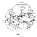
FIG 1 presents an isometric illustration of a FSW machine with an integrated accelerometer sensor -
FIG 2 presents a schematic perspective and cross-sectional view B-B of the progress of the tool in a tool breakage incident: a) Presentation of FSW process with a structurally intact tool; b) Presentation of FSW process upon pin breakage; c) Presentation of FSW process upon pin breakage and consequent destruction, i.e. deformation, of the shoulder part of the tool after crossing the area where the broken-off pin material is located (Prior art) -
FIG 3 presents an isometric illustration of FSW machine's reaction following the identification of a tool breakage -
FIG 4 presents tool breakage vibration signature readings and preset alarm limits -
FIG 5 presents a schematic perspective and cross-sectional view B-B of the progress of the tool upon a tool breakage incident with implemented accelerometer sensor and reaction logic: a) Presentation of FSW process upon pin breakage; b) Reaction of CNC controller after the identification of a tool breakage incident -
FIG 6 presents a schematic and cross-sectional view of a welding tool assembly for the FSW process -
FIG 7 presents an isometric illustration of a FSW machine during the procedure of drilling through the piece with a broken pin inside the welding trajectory to prevent a N.O.K. piece from entering further production steps. - The present invention provides a novel online tool verification technique for detecting tool breakage through measurement with a multi-axis accelerometer sensor.
Figure 1 illustrates different components of FSW machine. The FSW machine is based on a modified CNC-milling center withspindle head 1, rotary table 7 andswivel head 8, combined with x-, y- and z-axes to enable five-axis welding procedures. A conventionallaser measurement device 10 for verifying the tool breakage is stationed near thetool magazine 11. Amulti-axis accelerometer sensor 9 of present invention is mounted on thespindle head 1. The FSW welding process uses a specially designed welding tool assembly of ashoulder 2 and apin 3. On the machine rotary table 7, aclamping device 5 is positioned. Two pieces which are welded together to form acooler assembly 4 are positioned on theclamping device 5. Acooler assembly 4 with its two pieces to be welded together is only used as an example of the use of this invention. - For the weld quality assurance in serial welding production, it is very important to maintain control over the designed length H of
pin 3. The designed length H ofpin 3 assures the penetration depth H1 and consequently weld dimensions which assure the designed strength of the weld. The welding tool, especially its part calledpin 3, is subjected to high stresses generated during the tool's travel across the welding trajectory. In the serial production, tools' parts calledpin 3 randomly break after a certain quantity of welded parts. -
Figure 2 presents different position steps in a tool breakage incident.Figure 2a presents a structurally intact tool assembly ofshoulder 2 andpin 3 during the welding procedure in a cross-sectional view. -
Figure 2b shows the tool upon apin 3 breakage occurrence.Part 12 of abroken pin 3 stays inside theweld region 15. The welding process continues with remains 14 of thebroken pin 3 andshoulder 2. - Without integrating an online acceleration measurement procedure, a tool breakage cannot be identified and the welding process continues along the preprogrammed welding trajectory.
Part 12 ofbroken pin 3 stays inside the weld region and presents a hard inclusion. As the tool progresses across the weld trajectory, as shown inFigure 2c , the upper part of the tool namedshoulder 2 also passes acrosspart 12 ofbroken pin 3, consequently causingdeformation 13 of shape of the tool'sshoulder 2. This results in a complete destruction of both parts, thetool shoulder 2 and thepin 3. Consequently, the designed welding depth H1 is reduced to welding depth h1. - In
Figure 1 , a solution according to the present invention is presented. Amulti-axis accelerometer sensor 9, which detects acceleration amplitude in three directions x, y and z, is mounted on thespindle head 1. By measuring acceleration, tool breakage can be identified in real time. Theaccelerometer sensor 9 is integrated in a CNC controller in such a way that as the preset threshold of the acceleration is reached in respective axes, the controller reacts in the real time. As shown inFig. 3 , the welding program is immediately interrupted in the position of the tool breakage incident. The CNC controller reacts with a preprogrammed reaction and the welding tool is moved inreaction direction 16. This means that the CNC-welding program stops upon the execution of controller reaction in all axes except in the z-axis at the position of tool breakage occurrence as the FSW tool loses contact with the weld piece. This reaction logic prevents destruction of the shoulder's form due to a contact with an inclusion formed bypart 12 of thebroken pin 3, as shown onFig. 5 . -
Figure 4 presents vibration signals on x-axis upon tool breakage. To correctly set up the operation of theacceleration sensor 9, the signals must be monitored and recorded during the normal welding procedure. Based on the vibration noise measured during the welding procedure, the lower and upper amplitude threshold can be set. Upon identification of a high-amplitude noise spike above the amplitude threshold, a timed confirmation logic is deployed. During the confirmation period, the recognition logic continuously checks for signal samples above the amplitude threshold, and a tool breakage alarm is generated if a preset number of above-threshold samples is counted before the confirmation period ends. The acoustic signature of tool breakage in FSW process incident is significant and detectable in the measured direction. The noise amplitude upon tool breakage threshold is approximately three times higher compared to the noise of a normal process. -
Fig. 6 presents the design of an assembly of a welding tool. The design of welding tool assembly is done in a way that after apin 3 breakage event, followed by a preprogrammed reaction, the form ofshoulder 2 stays intact and only the broken pin, i.e. pin with remains 14, can be exchanged with anew pin 3. - The present invention reduces costs for tools manufacturing, enables the usage of different materials with different properties for pin and shoulder, and shortens the time for tool integrity verification between work pieces after the identification of a tool breakage.
- The invention also relates to automatic reaction logic of a CNC controller after the confirmation of a tool breakage. After the identification of tool breakage, the welding tool is deposited in a
tool magazine 11. Adrill tool 17 is then taken from the tool magazine and ahole 18 is drilled to identify the piece as N.O.K. In that way, a N.O.K. piece with a defective weld region characteristically differs from O.K. pieces with an adequate weld region. Upon subsequent weld surface machining, the hard inclusion remains of the pin material inside the weld region cannot destroy the milling tools. In an application of welding of cooler assembly, the N.O.K. parts will not pass the tightness test because of a hole drilled through a cooling channel.
Claims (3)
- Real time tool breakage detection during a friction stir welding process on an automated 5-axis CNC machine, characterized in that the detection of a tool breakage event is performed during the FSW process by measuring the acceleration amplitude in three directions x, y and z using a multi-axis accelerometer sensor (9) mounted on the spindle head (1) to identify high amplitude noise spikes.
- Real-time tool breakage detection according to claim 1, characterized in that the identification of a high amplitude noise spike above a preset acceleration amplitude threshold triggers the timed confirmation logic and during the confirmation period, the recognition logic continuously checks for signal samples above the amplitude threshold, and a tool breakage alarm is generated if a preset number of above-threshold samples are counted before the confirmation period ends.
- Real-time tool breakage detection according to claim 1 and 2, characterized in that when a preset threshold of the acceleration amplitude in respective axes is reached, the CNC controller reacts with a preprogrammed action in real time and the welding tool is moved in a reaction direction (16), and the marking of N.O.K. welded pieces is performed by drilling a hole in the same.
Priority Applications (1)
| Application Number | Priority Date | Filing Date | Title |
|---|---|---|---|
| EP14468004.8A EP2965858A1 (en) | 2014-07-11 | 2014-07-11 | Real-time tool breakage detection during the friction stir welding process |
Applications Claiming Priority (1)
| Application Number | Priority Date | Filing Date | Title |
|---|---|---|---|
| EP14468004.8A EP2965858A1 (en) | 2014-07-11 | 2014-07-11 | Real-time tool breakage detection during the friction stir welding process |
Publications (1)
| Publication Number | Publication Date |
|---|---|
| EP2965858A1 true EP2965858A1 (en) | 2016-01-13 |
Family
ID=51263356
Family Applications (1)
| Application Number | Title | Priority Date | Filing Date |
|---|---|---|---|
| EP14468004.8A Withdrawn EP2965858A1 (en) | 2014-07-11 | 2014-07-11 | Real-time tool breakage detection during the friction stir welding process |
Country Status (1)
| Country | Link |
|---|---|
| EP (1) | EP2965858A1 (en) |
Cited By (8)
| Publication number | Priority date | Publication date | Assignee | Title |
|---|---|---|---|---|
| CN106392432A (en) * | 2016-11-28 | 2017-02-15 | 上海和达汽车配件有限公司 | Tool device with welding and inspecting dual functions |
| CN108161290A (en) * | 2018-01-31 | 2018-06-15 | 湖州剑力金属制品有限公司 | The leakage preventing mechanism of auto parts and components spot welding fixture (SWFX) |
| CN108406193A (en) * | 2018-03-02 | 2018-08-17 | 宁波友智机械科技有限公司 | A kind of welding automatic fixture and its control method for agitating friction weldering |
| US20180297145A1 (en) * | 2015-10-21 | 2018-10-18 | Kawasaki Jukogyo Kabushiki Kaisha | Friction stir spot joining apparatus and friction stir spot joining method |
| DE102018001774A1 (en) * | 2018-03-06 | 2019-09-12 | Grenzebach Maschinenbau Gmbh | Device and method for avoiding an interruption of the welding process in friction stir welding, in particular a fracture of the friction pin. |
| CN112345726A (en) * | 2020-10-23 | 2021-02-09 | 安阳工学院 | Method for evaluating quality of friction stir welding seam |
| CN114952180A (en) * | 2022-08-01 | 2022-08-30 | 陕西斯瑞新材料股份有限公司 | Method for correcting deformation of thin-wall part after vacuum brazing and application thereof |
| CN115338530A (en) * | 2022-08-04 | 2022-11-15 | 北京九天行歌航天科技有限公司 | Stirring tool broken needle monitoring device and method based on force position torque |
Citations (18)
| Publication number | Priority date | Publication date | Assignee | Title |
|---|---|---|---|---|
| FR1152289A (en) * | 1956-06-11 | 1958-02-13 | Onera (Off Nat Aerospatiale) | Improvements to strain gauge sensors |
| US4636779A (en) | 1984-10-24 | 1987-01-13 | General Electric Company | Acoustic detection of tool break events in machine tool operations |
| US4918427A (en) | 1989-03-27 | 1990-04-17 | General Electric Company | Multi-level tool break detection using multi-mode sensing |
| DE4334933A1 (en) * | 1993-10-13 | 1995-04-20 | Fraunhofer Ges Forschung | Method and device for positive disconnection of hand-operated working equipment |
| WO1998013167A1 (en) | 1996-09-25 | 1998-04-02 | Esab Ab | Apparatus for friction stir welding |
| EP0752926B1 (en) | 1994-03-28 | 1998-05-27 | The Welding Institute | Friction stir welding |
| US5893507A (en) | 1997-08-07 | 1999-04-13 | The United States Of America As Represented By The Administrator Of The National Aeronautics And Space Administration | Auto-adjustable pin tool for friction stir welding |
| WO2000002704A1 (en) | 1998-07-09 | 2000-01-20 | Mts Systems Corporation | Control system for friction stir welding |
| US6050475A (en) | 1998-05-29 | 2000-04-18 | Mcdonnell Douglas Corporation | Method and apparatus for controlling downforce during friction stir welding |
| US6299050B1 (en) | 2000-02-24 | 2001-10-09 | Hitachi, Ltd. | Friction stir welding apparatus and method |
| EP1162029A1 (en) * | 2000-05-15 | 2001-12-12 | Prometec GmbH | Method and device for monitoring the wear of a tool |
| DE102005032170A1 (en) | 2005-07-09 | 2007-01-11 | Technische Universität Ilmenau | Friction friction welding tool and method and arrangement for online control of a friction stir welding process |
| JP2009082950A (en) * | 2007-09-28 | 2009-04-23 | Tokyu Car Corp | Friction stir welding system and friction stir welding method |
| EP2094428A1 (en) | 2006-12-05 | 2009-09-02 | The Boeing Company | Apparatus and method for measuring loads on a friction stir welding tool |
| US7992761B2 (en) | 2006-10-05 | 2011-08-09 | The Boeing Company | Process control system for friction stir welding |
| WO2012133411A1 (en) | 2011-03-29 | 2012-10-04 | 学校法人近畿大学 | Friction stir processing device and friction stir processing method |
| US8544714B1 (en) | 2012-11-15 | 2013-10-01 | Fluor Technologies Corporation | Certification of a weld produced by friction stir welding |
| US8556156B1 (en) | 2012-08-30 | 2013-10-15 | Apple Inc. | Dynamic adjustment of friction stir welding process parameters based on weld temperature |
-
2014
- 2014-07-11 EP EP14468004.8A patent/EP2965858A1/en not_active Withdrawn
Patent Citations (18)
| Publication number | Priority date | Publication date | Assignee | Title |
|---|---|---|---|---|
| FR1152289A (en) * | 1956-06-11 | 1958-02-13 | Onera (Off Nat Aerospatiale) | Improvements to strain gauge sensors |
| US4636779A (en) | 1984-10-24 | 1987-01-13 | General Electric Company | Acoustic detection of tool break events in machine tool operations |
| US4918427A (en) | 1989-03-27 | 1990-04-17 | General Electric Company | Multi-level tool break detection using multi-mode sensing |
| DE4334933A1 (en) * | 1993-10-13 | 1995-04-20 | Fraunhofer Ges Forschung | Method and device for positive disconnection of hand-operated working equipment |
| EP0752926B1 (en) | 1994-03-28 | 1998-05-27 | The Welding Institute | Friction stir welding |
| WO1998013167A1 (en) | 1996-09-25 | 1998-04-02 | Esab Ab | Apparatus for friction stir welding |
| US5893507A (en) | 1997-08-07 | 1999-04-13 | The United States Of America As Represented By The Administrator Of The National Aeronautics And Space Administration | Auto-adjustable pin tool for friction stir welding |
| US6050475A (en) | 1998-05-29 | 2000-04-18 | Mcdonnell Douglas Corporation | Method and apparatus for controlling downforce during friction stir welding |
| WO2000002704A1 (en) | 1998-07-09 | 2000-01-20 | Mts Systems Corporation | Control system for friction stir welding |
| US6299050B1 (en) | 2000-02-24 | 2001-10-09 | Hitachi, Ltd. | Friction stir welding apparatus and method |
| EP1162029A1 (en) * | 2000-05-15 | 2001-12-12 | Prometec GmbH | Method and device for monitoring the wear of a tool |
| DE102005032170A1 (en) | 2005-07-09 | 2007-01-11 | Technische Universität Ilmenau | Friction friction welding tool and method and arrangement for online control of a friction stir welding process |
| US7992761B2 (en) | 2006-10-05 | 2011-08-09 | The Boeing Company | Process control system for friction stir welding |
| EP2094428A1 (en) | 2006-12-05 | 2009-09-02 | The Boeing Company | Apparatus and method for measuring loads on a friction stir welding tool |
| JP2009082950A (en) * | 2007-09-28 | 2009-04-23 | Tokyu Car Corp | Friction stir welding system and friction stir welding method |
| WO2012133411A1 (en) | 2011-03-29 | 2012-10-04 | 学校法人近畿大学 | Friction stir processing device and friction stir processing method |
| US8556156B1 (en) | 2012-08-30 | 2013-10-15 | Apple Inc. | Dynamic adjustment of friction stir welding process parameters based on weld temperature |
| US8544714B1 (en) | 2012-11-15 | 2013-10-01 | Fluor Technologies Corporation | Certification of a weld produced by friction stir welding |
Cited By (20)
| Publication number | Priority date | Publication date | Assignee | Title |
|---|---|---|---|---|
| US10974344B2 (en) * | 2015-10-21 | 2021-04-13 | Kawasaki Jukogyo Kabushiki Kaisha | Friction stir spot joining apparatus and friction stir spot joining method |
| US20180297145A1 (en) * | 2015-10-21 | 2018-10-18 | Kawasaki Jukogyo Kabushiki Kaisha | Friction stir spot joining apparatus and friction stir spot joining method |
| CN106392432B (en) * | 2016-11-28 | 2018-09-11 | 上海和达汽车配件有限公司 | It is a kind of that there is welding and examine difunctional fitting device |
| CN106392432A (en) * | 2016-11-28 | 2017-02-15 | 上海和达汽车配件有限公司 | Tool device with welding and inspecting dual functions |
| CN108161290A (en) * | 2018-01-31 | 2018-06-15 | 湖州剑力金属制品有限公司 | The leakage preventing mechanism of auto parts and components spot welding fixture (SWFX) |
| CN108161290B (en) * | 2018-01-31 | 2023-06-23 | 湖州剑力金属制品有限公司 | Leakage-proof mechanism of spot welding fixture for automobile parts |
| CN108406193A (en) * | 2018-03-02 | 2018-08-17 | 宁波友智机械科技有限公司 | A kind of welding automatic fixture and its control method for agitating friction weldering |
| CN111819022B (en) * | 2018-03-06 | 2022-09-13 | 格林策巴赫机械制造有限公司 | Device and method for avoiding interruption of welding process, especially friction pin fracture in friction stir welding |
| KR20200115617A (en) * | 2018-03-06 | 2020-10-07 | 그렌체바흐 마쉬넨바우 게엠베하 | Apparatus and method for preventing interruption of the welding process during friction stir welding, in particular breakage of friction pins |
| CN111819022A (en) * | 2018-03-06 | 2020-10-23 | 格林策巴赫机械制造有限公司 | Device and method for avoiding interruption of welding process, especially friction pin fracture in friction stir welding |
| DE102018001774B4 (en) | 2018-03-06 | 2020-01-23 | Grenzebach Maschinenbau Gmbh | Device and method for avoiding an interruption of the welding process during friction stir welding, in particular a breakage of the friction pin. |
| KR102358314B1 (en) * | 2018-03-06 | 2022-02-08 | 그렌체바흐 마쉬넨바우 게엠베하 | Apparatus and method for preventing interruption of a welding process, in particular breakage of friction pins, during friction stir welding |
| US11325203B2 (en) | 2018-03-06 | 2022-05-10 | Grenzebach Maschinenbau Gmbh | Device and method for avoiding an interruption in the welding process during friction stir welding, in particular breakage of the friction pin |
| WO2019170182A1 (en) * | 2018-03-06 | 2019-09-12 | Grenzebach Maschinenbau Gmbh | Device and method for avoiding an interruption in the welding process during friction stir welding, in particular breakage of the friction pin |
| DE102018001774A1 (en) * | 2018-03-06 | 2019-09-12 | Grenzebach Maschinenbau Gmbh | Device and method for avoiding an interruption of the welding process in friction stir welding, in particular a fracture of the friction pin. |
| CN112345726A (en) * | 2020-10-23 | 2021-02-09 | 安阳工学院 | Method for evaluating quality of friction stir welding seam |
| CN112345726B (en) * | 2020-10-23 | 2022-11-18 | 安阳工学院 | Method for evaluating quality of friction stir welding seam |
| CN114952180A (en) * | 2022-08-01 | 2022-08-30 | 陕西斯瑞新材料股份有限公司 | Method for correcting deformation of thin-wall part after vacuum brazing and application thereof |
| CN115338530A (en) * | 2022-08-04 | 2022-11-15 | 北京九天行歌航天科技有限公司 | Stirring tool broken needle monitoring device and method based on force position torque |
| CN115338530B (en) * | 2022-08-04 | 2024-04-30 | 北京九天行歌航天科技有限公司 | Stirring tool broken needle monitoring device and method based on force position torque |
Similar Documents
| Publication | Publication Date | Title |
|---|---|---|
| EP2965858A1 (en) | Real-time tool breakage detection during the friction stir welding process | |
| US9528902B2 (en) | Die condition detection | |
| CA2679821C (en) | Friction stir welding spindle downforce and other control techniques, systems and methods | |
| US20090152253A1 (en) | Online weld inspection and repair method for resistance welding and weld-bonding | |
| RU2395070C2 (en) | Procedure for determination of mechanical characteristics of metal material | |
| JPH0375298B2 (en) | ||
| US9093515B2 (en) | Wire bonding capillary with working tip protrusion | |
| US5189514A (en) | Guidance system for automatic riveters | |
| EP2965851A1 (en) | Friction stir welding process with an offline tool breakage detection | |
| JP5080927B2 (en) | Friction stir welding system and friction stir welding method | |
| JP2014091187A (en) | Tool abnormality detection device, and tool abnormality detection method | |
| JP2001105159A (en) | Ultrasonic welder | |
| Jallageas et al. | Self-adjusting cutting parameter technique for drilling multi-stacked material | |
| JP7266596B2 (en) | Gear cutting method and gear cutting machine | |
| JP2596768B2 (en) | Detector for water jet processing | |
| Burford et al. | Early detection of volumetric defects using e-NDE during friction stir welding | |
| JP3290977B2 (en) | Abnormal stop control method in friction stir welding | |
| JP3901854B2 (en) | Quality inspection method for friction welding parts | |
| JP4931671B2 (en) | Inspection method | |
| JP4671523B2 (en) | Process management method and process management apparatus using friction stirring | |
| EP4269013A1 (en) | Manufacturing-log monitoring device, manufactured-object production system, and manufacturing-log monitoring method | |
| JP2000158295A (en) | Chip clogging detector for cutting tool for machine tool | |
| Jaśkiewicz | Implementation of automatic sample and composite element cutting technologies | |
| JP2015217479A (en) | Cutting work device and cutting work method | |
| CN110370079A (en) | A kind of cutter wear measurement method |
Legal Events
| Date | Code | Title | Description |
|---|---|---|---|
| PUAI | Public reference made under article 153(3) epc to a published international application that has entered the european phase |
Free format text: ORIGINAL CODE: 0009012 |
|
| AK | Designated contracting states |
Kind code of ref document: A1 Designated state(s): AL AT BE BG CH CY CZ DE DK EE ES FI FR GB GR HR HU IE IS IT LI LT LU LV MC MK MT NL NO PL PT RO RS SE SI SK SM TR |
|
| AX | Request for extension of the european patent |
Extension state: BA ME |
|
| STAA | Information on the status of an ep patent application or granted ep patent |
Free format text: STATUS: THE APPLICATION IS DEEMED TO BE WITHDRAWN |
|
| 18D | Application deemed to be withdrawn |
Effective date: 20160714 |